

Page 1
User's Guide
Page 2
Notations Used in This Guide
• Safety indications
The documentation and the projector use graphical symbols to show how to use the projector safely.
Please understand and respect these caution symbols in order to avoid injury to persons or property.
Warning
Caution
• General information indications
Attention
a
s Indicates a page where detailed information regarding a topic can be found.
g
[Name] Indicates the name of the buttons on the remote control or the control panel.
Menu Name Indicates Configuration menu items.
This symbol indicates information that, if ignored, could possibly result in personal injury or even death due to incorrect handling.
This symbol indicates information that, if ignored, could possibly result in personal injury or physical damage due to incorrect handling.
Indicates procedures which may result in damage or injury if sufficient care is not taken.
Indicates additional information and points which may be useful to know regarding a topic.
Indicates that an explanation of the underlined word or words in front of this symbol appears in the glossary of terms. See the "Glossary"
section of the "Appendix".
s "Glossary" p.168
Example: [Esc] button
Example:
Select Brightness from Image.
Image - Brightness
Page 3

Contents
3
Notations Used in This Guide ........................ 2
Introduction
Part Names and Functions ................................... 8
Front/Top................................................... 8
Rear.......................................................9
Interface....................................................9
Base...................................................... 10
Control Panel................................................11
Remote Control...............................................12
Replacing the remote control batteries.............................14
Remote control operating range ................................. 15
Removing and Attaching the Projector Lens Unit........................ 16
Attaching .................................................16
Removing .................................................17
Preparing the Projector
Installing the Projector ..................................... 20
Installation Requirements ........................................20
Changing the direction of the image (projection mode).................21
Screen Settings ............................................... 22
Adjusting the position of the image on the projected screen .............. 22
Displaying a Test Pattern ........................................23
Adjusting the Position of the Projected Image (Lens Shift)..................24
Adjusting the Image Size ........................................26
Correcting the Focus...........................................26
When using the short throw zoom lens ELPLU01 ......................26
Adjusting the Image Position.....................................27
Adjusting the Horizontal Tilt ......................................27
ID Settings..................................................28
Set the projector ID ..........................................28
Checking the Projector ID ...................................... 29
Setting the remote control ID ...................................29
Setting the Time..............................................29
Connecting Equipment ..................................... 31
Connecting a Computer ......................................... 31
Connecting Image Sources.......................................33
Connecting External Equipment ...................................35
Connecting a LAN Cable .........................................36
Connecting an HDBaseT Transmitter ................................37
Attaching the Cable Cover ....................................... 38
Attaching .................................................38
Basic Usage
Projecting Images ......................................... 40
Automatically Detect Input Signals and Change the Projected Image (Source Search)
.......................................................... 40
Switching to the Target Image by Remote Control....................... 41
Adjusting the Volume ..........................................41
Adjusting Projected Images ................................ 42
Correcting Distortion in the Projected Image ...........................42
H/V-Keystone..............................................43
Quick Corner ...............................................43
Curved Surface.............................................44
Corner Wall ................................................ 47
Selecting the Projection Quality (Selecting Color Mode)...................49
Projecting 3D images .........................................50
Changing the Aspect Ratio of the Projected Image ......................50
Changing methods.......................................... 51
Adjusting the Image ...........................................53
Hue, Saturation, and Brightness Adjustment .........................53
Gamma Adjustment .......................................... 54
Frame Interpolation (EB-G6900WU only) ............................ 55
Page 4

Contents
4
Useful Functions
Multi-Projection Function . ................................. 57
Adjusting the Position of the Projected Image.......................... 57
Point Correction............................................ 57
Checking the Color Mode ........................................ 59
Adjust the Edges of the Images (Edge Blending) .........................59
Adjusting the brightness of the lamp ..............................59
Performing edge blending.....................................59
Adjusting to Match Colors ........................................ 63
Scaling an Image (Scale) ......................................... 64
Projection Functions ....................................... 66
Projecting Two Images Simultaneously (Split Screen) .....................66
Operating procedures........................................ 66
Restrictions during split screen projection ...........................68
Hiding the Image and Sound Temporarily (A/V Mute) .....................69
Freezing the Image (Freeze)......................................70
Enlarging Part of the Image (E-Zoom)................................ 70
Saving a User's Logo...........................................71
Memory Function .......................................... 73
Saving/Loading/Erasing the Memory ................................ 73
Scheduling Function ....................................... 75
Saving a Schedule ............................................. 75
Setting Methods............................................75
Editing a schedule ...........................................76
Security Functions ......................................... 78
Managing Users (Password Protection) ............................... 78
Kinds of Password Protection...................................78
Setting Password Protection ....................................78
Entering the Password........................................79
Restricting Operation ...........................................80
Control Panel Lock ...........................................80
Remote control button lock .................................... 81
Anti-Theft Lock ............................................... 81
Installing the wire lock ........................................82
Configuration Menu
Using the Configuration Menu .............................. 84
List of Functions ........................................... 85
Configuration Menu Table .......................................85
Network menu............................................. 86
Image Menu .................................................87
Signal Menu ................................................. 88
Settings Menu................................................90
Extended Menu...............................................91
Network Menu............................................... 95
Notes on operating the Network menu .............................95
Soft keyboard operations......................................96
Basic menu ................................................97
Wired LAN menu ............................................97
Mail menu................................................ 98
Others menu..............................................99
Reset menu ............................................... 100
Info Menu (Display Only) ........................................100
Reset Menu .................................................101
Troubleshooting
Using the Help ........................................... 104
Problem Solving .......................................... 105
Reading the Indicators ......................................... 105
When the Indicators Provide No Help ............................... 109
Problems Relating to Images ..................................... 110
No images appear .......................................... 110
Moving images are not displayed ................................110
Projection stops automatically.................................. 111
The message Not supported is displayed ........................... 111
Page 5

Contents
5
The message No Signal is displayed .............................. 111
Images are fuzzy, out of focus, or distorted ......................... 112
Interference or distortion appear in images ......................... 112
The image is truncated (large) or small, the aspect is not suitable, or the image has
been reversed ............................................. 113
Image colors are not right..................................... 114
Images appear dark ......................................... 115
Problems when Projection Starts .................................. 115
The projector does not turn on................................. 115
Other Problems ..............................................116
No sound can be heard from the speakers, or the sound is faint ........... 116
The remote control does not work............................... 117
Nothing appears on the external monitor .......................... 118
I want to change the language for messages and menus ................ 118
Email is not received even if a problem occurs in the projector............ 118
The battery that saves your clock settings is running low. is displayed....... 119
Cannot change settings using a Web browser....................... 119
Maintenance
Cleaning ................................................. 121
Cleaning the Projector's Surface ...................................121
Cleaning the Lens............................................ 121
Cleaning the Air Filter.......................................... 121
Cleaning the air filter........................................ 121
Replacing Consumables ................................... 124
Replacing the Lamp ........................................... 124
Lamp replacement period .....................................124
How to replace the lamp......................................124
Resetting the lamp hours ..................................... 127
Replacing the Air Filter ......................................... 127
Air filter replacement period ................................... 127
How to replace the air filter .................................... 127
Notes on Transportation .................................. 129
Moving Nearby .............................................. 129
When Transporting ........................................... 129
Preparing packaging........................................ 129
Notes when packing and transporting............................ 129
Image Maintenance ....................................... 130
Panel Alignment ............................................. 130
Color Uniformity ............................................. 131
Adjusting the Lens Balance ...................................... 133
Appendix
Monitoring and Controlling ............................... 138
About EasyMP Monitor .........................................138
About Message Broadcasting.................................. 138
Changing Settings Using a Web Browser (Web Control) ...................138
Projector setup ............................................ 138
Displaying the Web Control screen ............................... 138
Using the Mail Notification Function to Report Problems.................. 139
Reading Error Notification Mail................................. 139
Management Using SNMP ...................................... 140
Displaying the Web Remote Screen ................................ 140
ESC/VP21 Commands ..........................................141
Command list ............................................. 141
Cable layouts ............................................. 142
About PJLink ................................................143
About Crestron RoomView
Operating a projector from your computer ......................... 144
Optional Accessories and Consumables .................... 148
Optional Accessories .......................................... 148
Consumables............................................... 148
Screen Size and Projection Distance ........................ 150
Projection Distance (For EB-G6900WU) .............................. 150
Standard zoom lens ELPLS06................................... 150
Short throw zoom lens ELPLU01.................................151
Rear projection wide lens ELPLR03 ............................... 151
..................................... 143
®
Page 6

Contents
Middle throw zoom lens ELPLM04 ............................... 152
Middle throw zoom lens ELPLM05 ............................... 153
Long throw zoom lens ELPLL06 ................................. 154
Projection Distance (For EB-G6800) . . . . . . . . . . . . . . . . . . . . . . . . . . . . . . . . 155
Standard zoom lens ELPLS06 ...................................155
Short throw zoom lens ELPLU01 ................................. 156
Rear projection wide lens ELPLR03 ............................... 157
Middle throw zoom lens ELPLM04 ............................... 157
Middle throw zoom lens ELPLM05 ............................... 158
Long throw zoom lens ELPLL06 ................................. 159
Supported Monitor Displays ............................... 161
Supported Resolutions ......................................... 161
Computer signals (analog RGB) ................................. 161
Component Video .......................................... 161
Composite video ........................................... 161
Input signal from the HDMI port and DisplayPort (EB-G6900WU) . . . ....... 162
Input signal from the HDMI port and DisplayPort (EB-G6800) . . . .......... 162
Input signals from SDI port (EB-G6900WU only)...................... 162
6
Specifications ............................................ 164
Projector General Specifications...................................164
Appearance .............................................. 167
Glossary ................................................. 168
General Notes ............................................ 170
Trademarks and Copyrights ......................................170
Index .................................................... 171
Page 7

Introduction
This chapter explains the names for each part.
Page 8
Part Names and Functions
8
The illustrations in this guide are for EB-G6900WU (with the standard
zoom lens ELPLS06 attached).
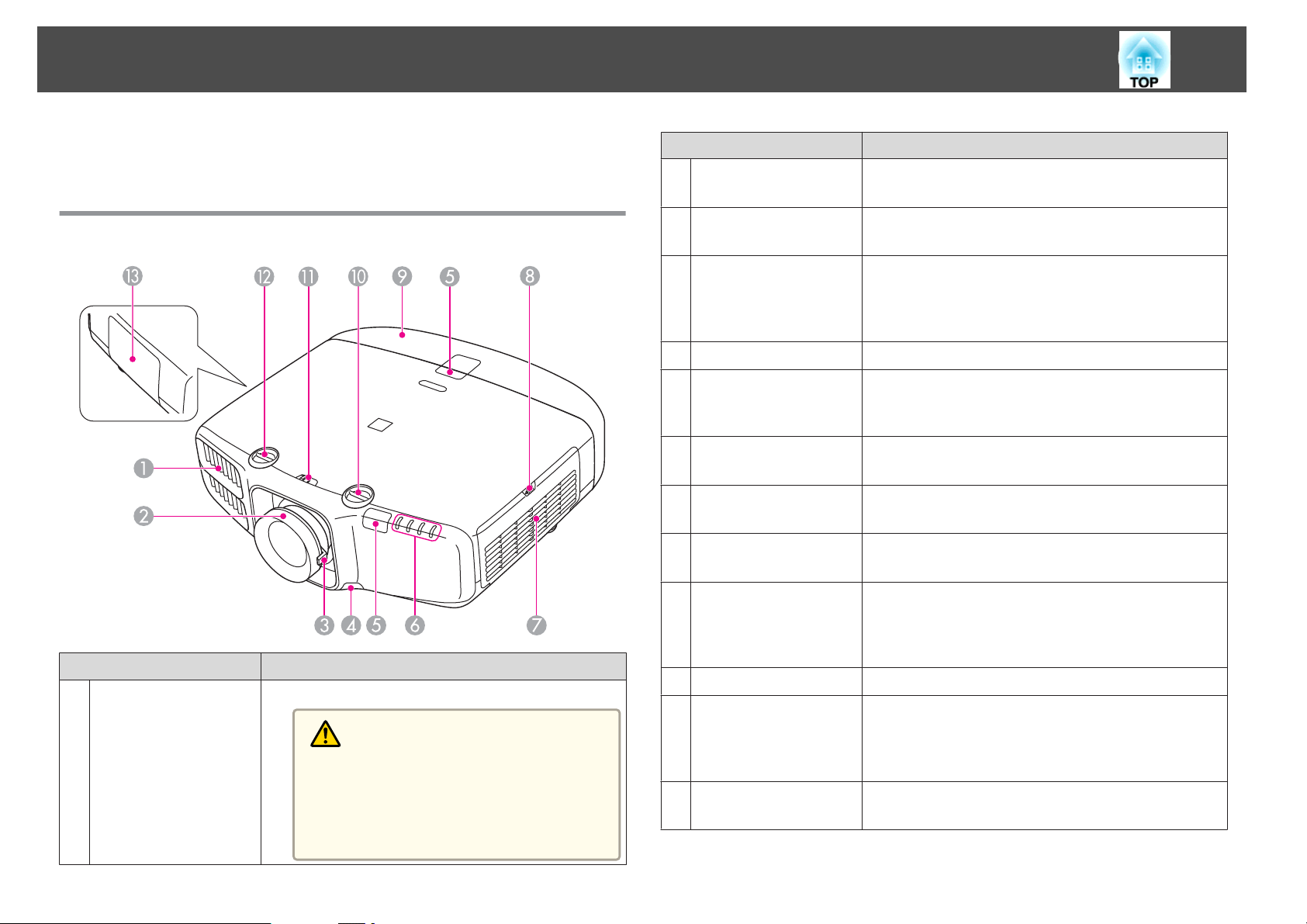
Front/Top
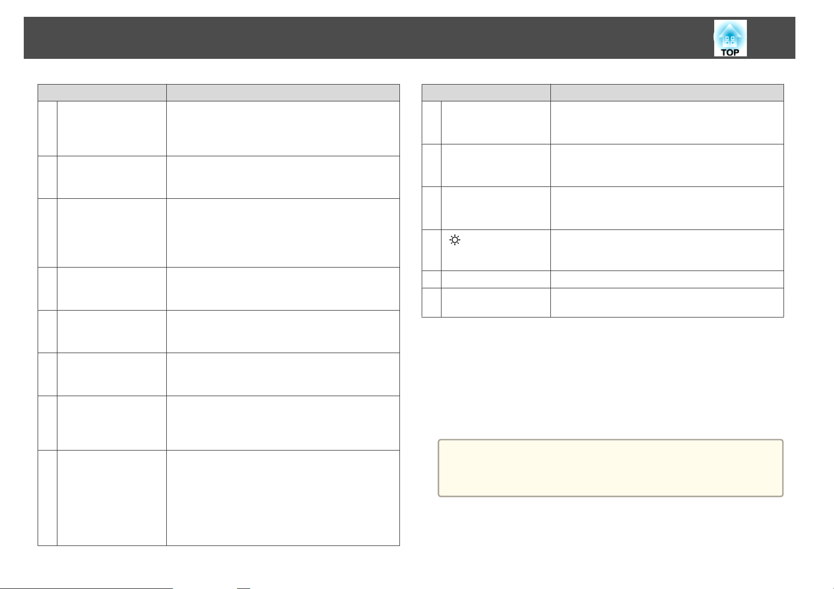
Name Function
Focus ring
B
Zoom ring
C
Lens unit removal
D
button
Remote receiver
E
Status indicators
F
Air intake vent
G
(air filter)
Air filter cover
H
operation knob
Cable cover
I
Adjusts the image focus.
s "Correcting the Focus" p.26
Adjusts the image size.
s "Adjusting the Image Size" p.26
When replacing the lens unit, press this button and then
remove the lens unit.
s "Removing and Attaching the Projector Lens Unit"
p.16
Receives signals from the remote control.
The color of the indicators and whether they are flashing
or lit indicate the status of the projector.
"Reading the Indicators" p.105
s
Takes in air to cool the projector internally.
s "Cleaning the Air Filter" p.121
Use this knob to open the air filter cover.
s "Replacing the Air Filter" p.127
Cover for the rear interface cable connection section.
s "Attaching the Cable Cover" p.38
Air exhaust vent
A
Name Function
Exhaust vent for air used to cool the projector internally.
Caution
While projecting, do not put your face or hands
near the air exhaust vent, and do not place objects
that may become warped or damaged by heat near
the vent. Hot air from the air exhaust vent could
cause burns, warping, or accidents to occur.
Vertical lens shift dial
J
Lens shift dial lock
K
Horizontal lens shift
L
dial
Lamp cover
M
Turn the dial to move the position of the projected image
up or down.
s "Adjusting the Position of the Projected Image (Lens
Shift)" p.24
Locks or releases the lens shift dials.
Turn the dial to move the position of the projected image
left or right.
s "Adjusting the Position of the Projected Image (Lens
Shift)" p.24
Open when replacing the projector's lamp.
s "Replacing the Lamp" p.124
Page 9
Part Names and Functions
9
Rear
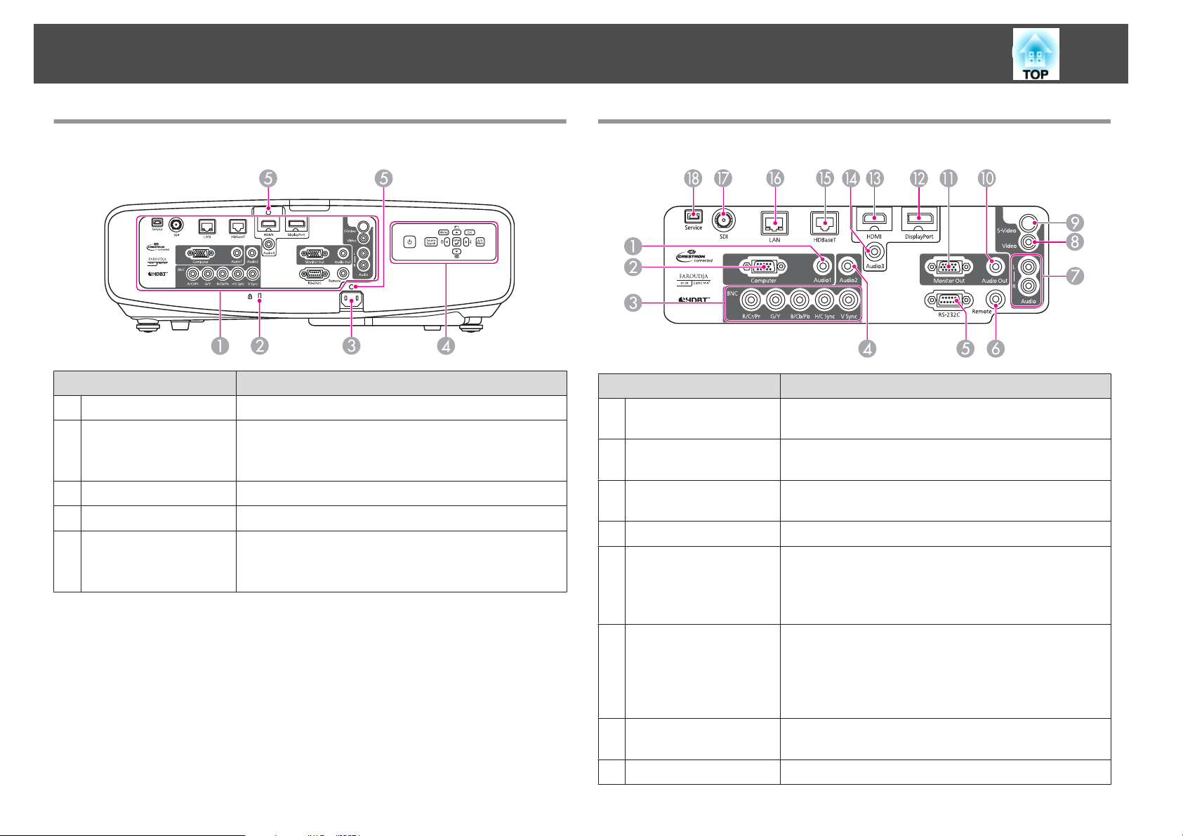
Interface
A
Security slot
B
Power inlet
C
Control panel
D
Cable holder
E
Name Function
s "Interface" p.9
The security slot is compatible with the Microsaver
Security System manufactured by Kensington.
s "Anti-Theft Lock" p.81
Connects to the power cable.
s "Control Panel" p.11
Insert the supplied cable clamp here to prevent the cable
from falling out.
s Quick Reference
Interface
Name Function
Audio1 port
A
Computer port
B
BNC port
C
Audio2 port
D
RS-232C port
E
Inputs audio from equipment connected to the Computer
port.
For analog RGB signals from a computer and component
video signals from other video sources.
For analog RGB signals from a computer and component
video signals from other video sources.
Inputs audio from equipment connected to the BNC port.
When controlling the projector from a computer, connect
it to the computer with an RS-232C cable. This port is for
control use and should not normally be used.
s "ESC/VP21 Commands" p.141
Remote port
F
Audio-L/R port
G
Video port
H
Connects the optional remote control cable set and inputs
signals from the remote control. When the remote control
cable is plugged into the Remote port, the remote receiver
on the projector is disabled.
s "Optional Accessories" p.148
Inputs audio from equipment connected to the Video port
or the S-Video port.
Inputs composite video signals from video sources.
Page 10
Part Names and Functions
10
Name Function
S-Video port
I
Audio Out port
J
Monitor Out port
K
DisplayPort
L
HDMI port
M
Audio3 port
N
HDBaseT port
O
LAN port
P
SDI port (EB-G6900WU
Q
only)
For S-video signals from video sources.
Outputs audio from the currently projected image to an
external speaker.
Outputs to an external monitor the analog signal from the
computer connected to the Computer port or the BNC
port. You cannot output signals input from other ports or
component video signals.
Inputs video signals from DisplayPort compatible
computers. This projector is compatible with
Inputs video signals from HDMI compatible video
equipment and computers. This projector is compatible
with
HDCPg.
Inputs audio from equipment connected to the
DisplayPort or the HDMI port.
Connects a LAN cable to the optional HDBaseT
Transmitter.
s "Connecting an HDBaseT Transmitter" p.37
s "Optional Accessories" p.148
Connects a LAN cable to connect to a network.
Inputs SDI signals from a video equipment. This projector
supports SD-SDI (Standard Definition) and HD-SDI
(High Definition).
HDCPg.
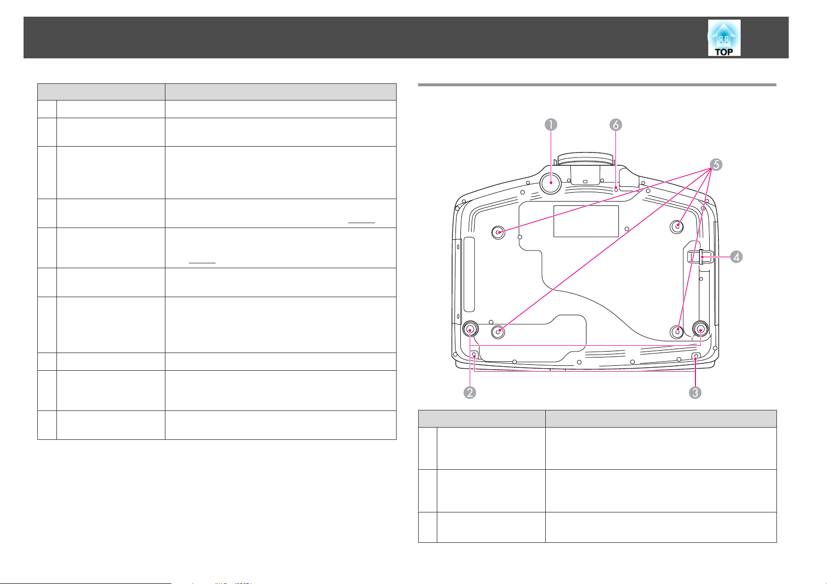
Base
Service port
R
This port is used by maintenance personnel to control the
projector. This should not normally be used.
Name Function
Front adjustable foot
A
Rear feet
B
Screw holes to fix the
C
cable cover
When setup on a surface such as a desk, extend the foot to
adjust the position of the image.
s "Adjusting the Image Position" p.27
When setup on a surface such as a desk, turn to extend and
retract to adjust the horizontal tilt.
s "Adjusting the Horizontal Tilt" p.27
Screw holes to fix the cable cover in place.
s "Attaching the Cable Cover" p.38
Page 11
Part Names and Functions
11
Name Function
Security cable
D
installation point
Ceiling mount fixing
E
points (four points)
Screw hole for the
F
screw to fix the lens
unit removal button
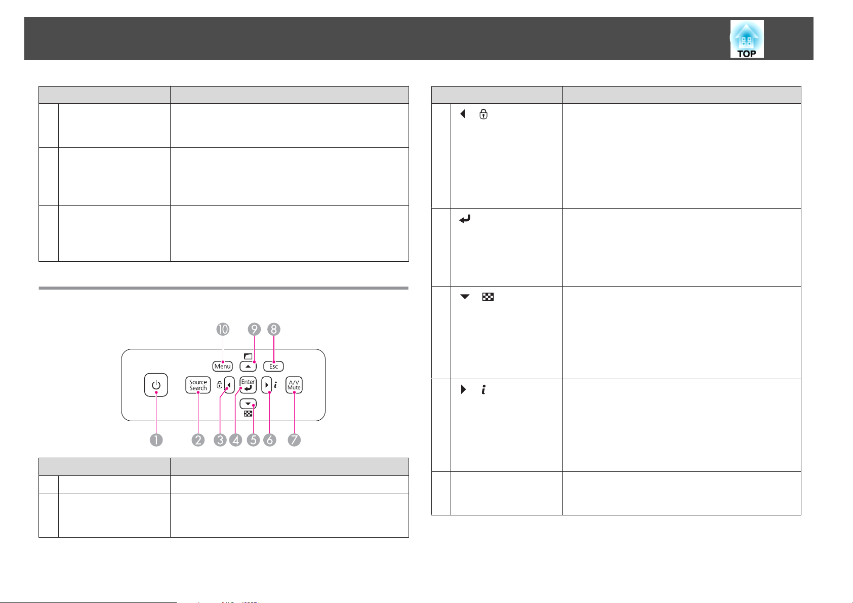
Control Panel
Name Function
[t] button
A
[Source Search]
B
button
Pass a commercially available wire lock through here and
lock it in place.
s "Installing the wire lock" p.82
Attach the optional Ceiling Mount here when suspending
the projector from a ceiling.
s "Installing the Projector" p.20
s "Optional Accessories" p.148
When installing a lens unit, use this screw hole to fix the
lens unit removal button using the screw supplied.
s "Removing and Attaching the Projector Lens Unit"
p.16
Turns the projector power on or off.
Changes to the next input source that is sending an image.
s "Automatically Detect Input Signals and Change the
Projected Image (Source Search)" p.40
Name Function
C
[ ]/[ ] buttons
D
[ ] button
E
[ ]/[ ] buttons
F
[ ] /[ ] buttons
[A/V Mute] button
G
• Displays the Control Panel Lock screen allowing you to
make settings to lock the control panel buttons.
"Restricting Operation" p.80
s
• If pressed when the Configuration menu or the Help
screen is displayed, this button selects menu items and
setting values.
s "Using the Configuration Menu" p.84
s "Using the Help" p.104
• When the Configuration menu or the Help screen is
displayed, it accepts and enters the current selection and
moves to the next level.
• If pressed while projecting analog RGB signals from the
Computer port or the BNC port, you can automatically
optimize Tracking, Sync., and Position.
• Displays a test pattern.
s "Displaying a Test Pattern" p.23
• If pressed when the Configuration menu or the Help
screen is displayed, this button selects menu items and
setting values.
s "Using the Configuration Menu" p.84
s "Using the Help" p.104
• Displays the Info menu from the Configuration menu.
s "Info Menu (Display Only)" p.100
• If pressed when the Configuration menu or the Help
screen is displayed, this button selects menu items and
setting values.
s "Using the Configuration Menu" p.84
s "Using the Help" p.104
Turns the video and audio on or off.
s "Hiding the Image and Sound Temporarily (A/V
Mute)" p.69
Page 12
Part Names and Functions
12
Name Function
[Esc] button
H
I
[ ]/[ ] buttons
[Menu] button
J
• Stops the current function.
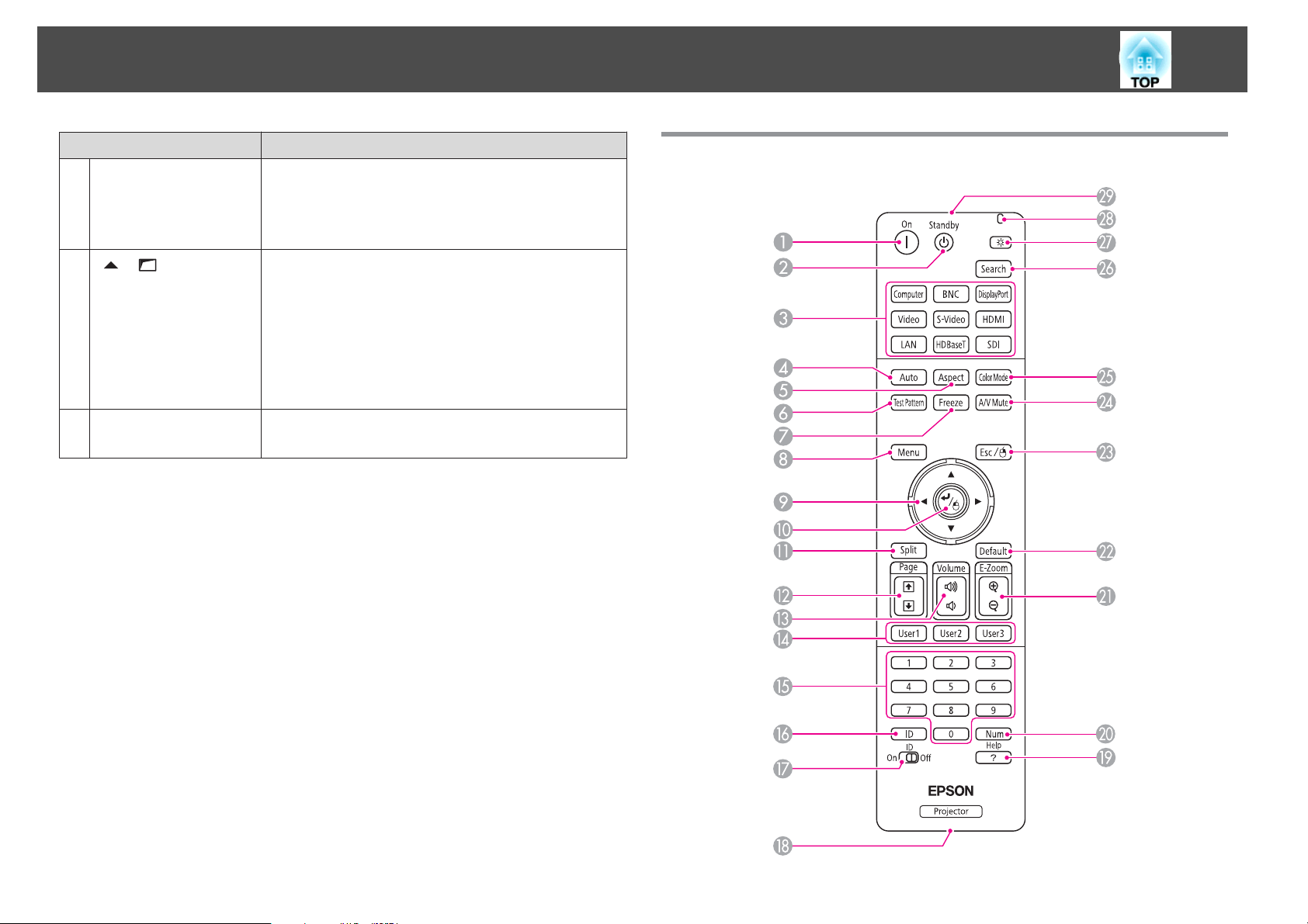
Remote Control
• If pressed when the Configuration menu is displayed, it
moves to the previous menu level.
s "Using the Configuration Menu" p.84
• Performs screen adjustments using the settings in
Geometric Correction from the Configuration menu.
s Settings - Geometric Correction p.90
• If pressed when the Configuration menu or the Help
screen is displayed, this button selects menu items and
setting values.
s "Using the Configuration Menu" p.84
s "Using the Help" p.104
Displays and closes the Configuration menu.
s "Using the Configuration Menu" p.84
Page 13
Part Names and Functions
13
Name Function
A
[ ] button
[t] button
B
Change input buttons
C
[Auto] button
D
[Aspect] button
E
[Test Pattern] button
F
[Freeze] button
G
[Menu] button
H
I
[ ][ ][ ][ ]
buttons
Turns the projector on.
Turns the projector off.
Changes to images from each input port.
s "Switching to the Target Image by Remote Control"
p.41
The [SDI] button is only available for EB-G6900WU.
The [LAN] button is not available for this projector.
If pressed while projecting analog RGB signals from the
Computer port or the BNC port, you can automatically
optimize Tracking, Sync., and Position.
Each time the button is pressed, the aspect mode changes.
s "Changing the Aspect Ratio of the Projected Image "
p.50
Displays a test pattern.
s "Displaying a Test Pattern" p.23
Images are paused or unpaused.
s "Freezing the Image (Freeze)" p.70
Displays and closes the Configuration menu.
s "Using the Configuration Menu" p.84
• When the Configuration menu or the Help screen is
displayed, pressing these buttons selects menu items
and setting values.
s "Using the Configuration Menu" p.84
• When using the optional wireless mouse receiver,
pressing these buttons moves the pointer.
s "Optional Accessories" p.148
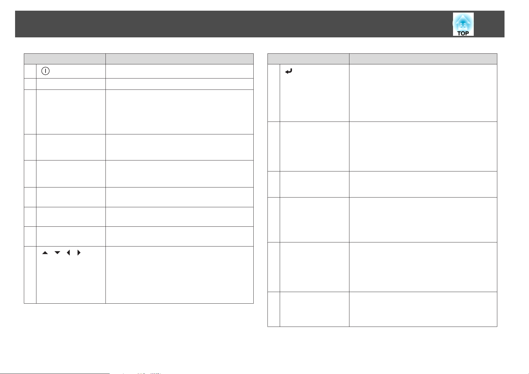
Name Function
J
[ ] button
[Split] button
K
[Page] buttons
L
[[][]]
[Volume] buttons
M
[a][b]
[User1] button
N
[User2] button
[User3] button
Numeric buttons
O
• When the Configuration menu or the Help screen is
displayed, it accepts and enters the current selection and
moves to the next level.
s "Using the Configuration Menu" p.84
• Acts as a mouse's left button when using the optional
wireless mouse receiver.
s "Optional Accessories" p.148
Each time the button is pressed, the image changes
between projecting two images simultaneously by
splitting the projected screen, or projecting one image as
normal.
s "Projecting Two Images Simultaneously (Split Screen)
" p.66
When using the optional wireless mouse receiver, you can
change the PowerPoint file page during projection by
pressing the page up/page down buttons.
Adjusts the volume for audio output from the Audio Out
port.
[a] Decreases the volume.
[b] Increases the volume.
s "Adjusting the Volume" p.41
Select any frequently used item from the eight available
Configuration menu items, and assign it to one of these
buttons. By pressing the button, the assigned menu item
selection/adjustment screen is displayed, allowing you to
make one-touch settings/adjustments.
s "Settings Menu" p.90
• Enter the Password.
s "Setting Password Protection" p.78
• Use this button to enter numbers in Network settings
from the Configuration menu.
Page 14
Part Names and Functions
14
Name Function
[ID] button
P
[ID] switch
Q
Remote port
R
[Help] button
S
[Num] button
T
[E-Zoom] buttons
U
[z][x]
[Default] button
V
[Esc] button
W
Hold down this button and press the numeric buttons to
select the ID for the projector you want to operate using
the remote control.
s "ID Settings" p.28
Use this switch to enable (On)/disable (Off) ID settings for
the remote control.
s "ID Settings" p.28
Connects the optional remote control cable set and
outputs signals from the remote control.
s "Optional Accessories" p.148
When the remote control cable is plugged into this remote
port, the remote control light-emitting is disabled.
Displays and closes the Help screen which shows you how
to deal with problems if they occur.
s "Using the Help" p.104
Hold down this button and press the numeric buttons to
enter passwords and numbers.
s "Setting Password Protection" p.78
Enlarges or reduces the image without changing the
projection size.
s "Enlarging Part of the Image (E-Zoom)" p.70
Enabled when [Default]: Reset is displayed on the
configuration menu guide. The settings being adjusted are
returned to their default values.
s "Using the Configuration Menu" p.84
• Stops the current function.
• If pressed when the Configuration menu is displayed, it
moves to the previous level.
s "Using the Configuration Menu" p.84
• Acts as a mouse's right button when using the optional
wireless mouse receiver.
s "Optional Accessories" p.148
Name Function
[A/V Mute] button
X
[Color Mode] button
Y
[Search] button
Z
a
[ ] button
Indicator
b
Remote control light-
c
emitting area
Turns the video and audio on or off.
s "Hiding the Image and Sound Temporarily (A/V
Mute)" p.69
Each time the button is pressed, the Color Mode changes.
s "Selecting the Projection Quality (Selecting Color
Mode)" p.49
Changes to the next input source that is sending an image.
s "Automatically Detect Input Signals and Change the
Projected Image (Source Search)" p.40
Illuminates the buttons on the remote control for
approximately 15 seconds. This is useful when using the
remote control in the dark.
A light is emitted when outputting remote control signals.
Outputs remote control signals.
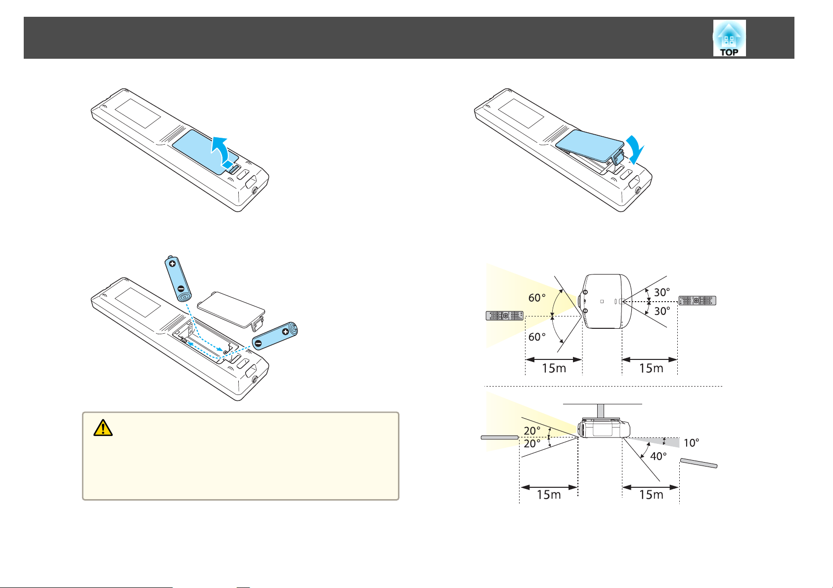
Replacing the remote control batteries
If delays in the responsiveness of the remote control occur or if it does not
operate after it has been used for some time, it probably means that the
batteries are becoming flat. When this happens, replace them with new
batteries. Have two AA size alkaline or manganese batteries ready. You
cannot use other batteries except for the AA size alkaline or manganese.
Attention
Make sure you read the following manual before handling the batteries.
s Safety Instructions
a
Remove the battery cover.
While pushing the battery compartment cover catch, lift the cover
up.
Page 15
Part Names and Functions
15
b
Replace the old batteries with new batteries.
Remote control operating range
Caution
Check the positions of the (+) and (-) marks inside the battery holder to
ensure the batteries are inserted the correct way.
If the batteries are not used correctly, they could explode or leak causing
a fire, injury, or damage to the product.
c
Replace the battery cover.
Press the battery compartment cover until it clicks into place.
Page 16

Part Names and Functions
• To restrict reception of the operation signals from the remote
a
control, set Remote Receiver.
s Settings - Remote Receiver p.90
• When using a remote control provided with other Epson projectors,
set the Remote Control Type.
s Extended - Operation - Remote Control Type p.91
The operating range depends on the remote control that you use.
Removing and Attaching the Projector Lens Unit
Attaching
Attention
• Do not attach the lens unit when the projector's lens insertion section is
facing up. Dust or dirt could enter the projector.
• Only use the specified lens. See the following for a list of lenses that can be
used with the projector.
s "Optional Accessories" p.148
16
Turn the torque ring on the lens unit to adjust the torque for the
zoom ring.
a
b
Turn the focus ring clockwise until it cannot go any further.
Insert the lens unit straight into the projector's lens socket with
the white dot at the top, and then turn it clockwise until you hear
it click into place.
c
d
Tighter
A
Looser
B
Turn the lens unit counterclockwise and make sure that it does
not come out of the socket.
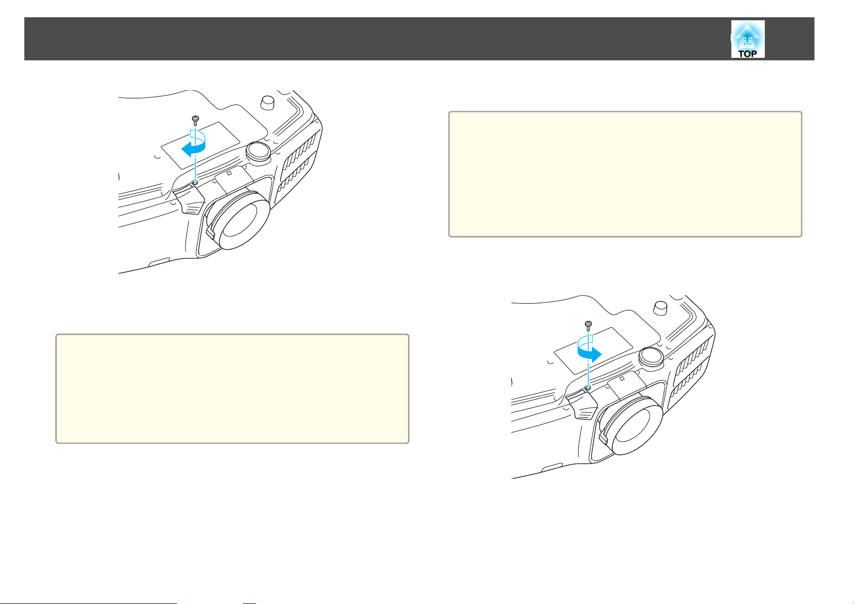
Fix the lens unit removal button with the screw supplied with the
lens unit.
Page 17
Part Names and Functions
17
Removing
Attention
• Only remove the lens unit when necessary. If dust or dirt enter the projector,
projection quality deteriorates and it could cause a malfunction.
• Try not to touch the lens section with your hand or fingers. If fingerprints or
oils are left on the surface of the lens, projection quality deteriorates.
• If the lens shift has been done, set the lens shift to the center before replacing
the lens unit.
s "Adjusting the Position of the Projected Image (Lens Shift)" p.24
Make sure you fix the lens unit removal button with the screw to
prevent the lens unit from being stolen.
Attention
• Store the projector with the lens unit installed.
If the projector is stored without the lens unit, dust and dirt may get inside
the projector and cause malfunctions or lower the quality of projection.
• When the projector is facing up (35 to 150 degrees) or down (-35 to -150
degrees), tighten the lens torque ring. Note that it could malfunction if it is
over tightened.
a
b
When the lens unit removal button is fixed with a screw, remove
the screw.
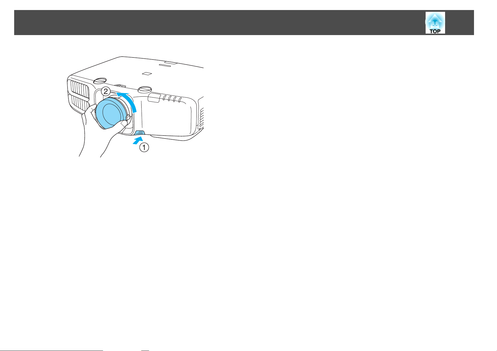
While pressing the lens unit removal button, turn the lens unit
counterclockwise until you hear it click.
Page 18
Part Names and Functions
18
c
Pull the lens unit straight out as it is released.
Page 19

Preparing the Projector
This chapter explains how to install the projector and connect projection sources.
Page 20
Installing the Projector
20
Installation Requirements
The projector can be mounted on a ceiling or placed on a desk. Also, it can
be mounted at a tilted angle, so you can flexibly project images to various
places.
Warning
• A special method of installation is required when suspending the projector
from a ceiling (ceiling mount). If installation work is not carried out
correctly, the projector could fall down. This may result in injury or
accidents.
Contact your dealer or the nearest address provided in the Support and
Service Guide if you want to use this installation method. s Epson Projector
Contact List
• If you use adhesives on the Ceiling mount fixing points to prevent the screws
from loosening, or if you use things such as lubricants or oils on the
projector, the projector case may crack causing it to fall from its ceiling
mount. This could cause serious injury to anyone under the ceiling mount
and could damage the projector.
When installing or adjusting the ceiling mount, do not use adhesives to
prevent the screws from loosening and do not use oils or lubricants and so
on.
• Do not cover the projector's air intake vent or air exhaust vent. If either of
the vents are covered, the internal temperature could rise and cause a fire.
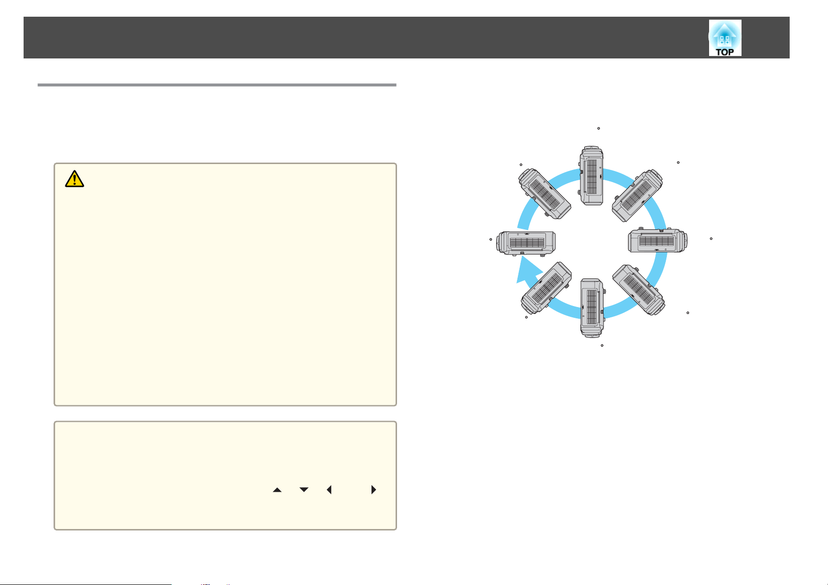
The projector can be installed at the following angles.
Vertical: Can be installed at any angle in a complete 360 degrees.
90
45
0
-45
135
180
-135
-90
Horizontal: Can be tilted within the range of expansion and contraction for
the rear feet.
s
"Adjusting the Horizontal Tilt" p.27
a
• An optional ceiling mount is required when suspending the
projector from a ceiling.
s "Optional Accessories" p.148
• When mounted on a ceiling, set Inv Direction Button to On so that
the operations and movement of the [
buttons on the control panel match.
Extended - Operation - Inv Direction Button p.91
s
], [ ], [ ], and [ ]
Page 21
Installing the Projector
21
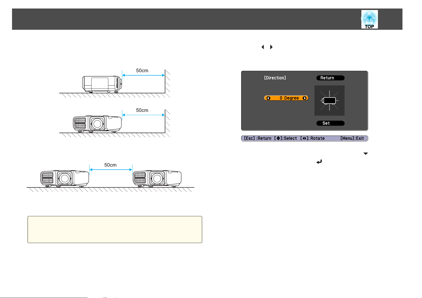
Make sure there is a gap of at least 50 cm between the wall and the air
exhaust vent and the air intake vent.
Air exhaust vent
Air intake vent
When setting up multiple projectors, make sure there is a gap of at least
50 cm between the projectors.
c
Use the [ ][ ] buttons to set the projector's installation angle.
Each time you press one of the buttons, the angle of tilt changes by
15 degrees. Set as close to the actual setup angle as possible.
d
Changing the direction of the image (projection mode)
When you have finished making settings, use the [ ] button to
select Set, and then press the [
] button.
When installation is complete, set the Direction from the configuration
menu according to the vertical installation angle.
Attention
Make sure you set Direction correctly. The lamp's operating life may be
reduced if it is not set.
Press the [Menu] button while projecting.
a
Select Direction from Extended.
b
You can change the direction of the image using Projection mode from the
Configuration menu.
s
Extended - Projection p.91
Page 22
Installing the Projector
22
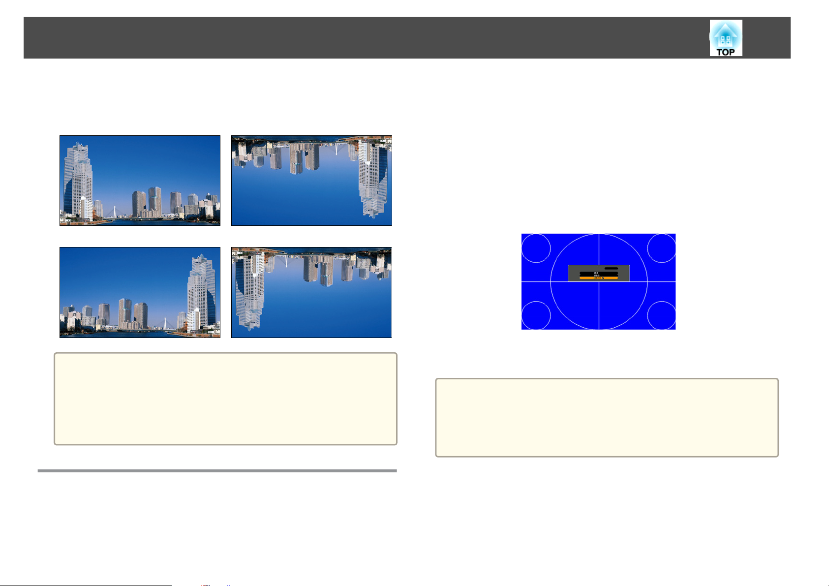
When Front is the standard, the image directions for each projection mode
are as follows.
Front (default) Front/Ceiling
Rear Rear/Ceiling
• You can change the setting as follows by pressing down the [A/V
a
Mute] button on the remote control for about five seconds.
FrontWFront/Ceiling
• Make sure you check the Direction setting when you change the
projector's installation position.
s Extended - Direction p.91
a
b
c
d
e
a
Press the [Menu] button while projecting.
s
"Using the Configuration Menu" p.84
Select Display from Extended.
Select Screen Type from Screen.
Select the screen's aspect ratio.
The shape of the background test pattern changes depending on the
setting.
Press the [Menu] button to finish making settings.
• When you change the Screen Type, adjust the aspect ratio for the
projected image as well.
s "Changing the Aspect Ratio of the Projected Image " p.50
• This function does not support Message Broadcasting (an EasyMP
Monitor plugin).
Screen Settings
Set the Screen Type according to the aspect ratio of the screen being used.
The area where the image is displayed matches the shape of the screen.
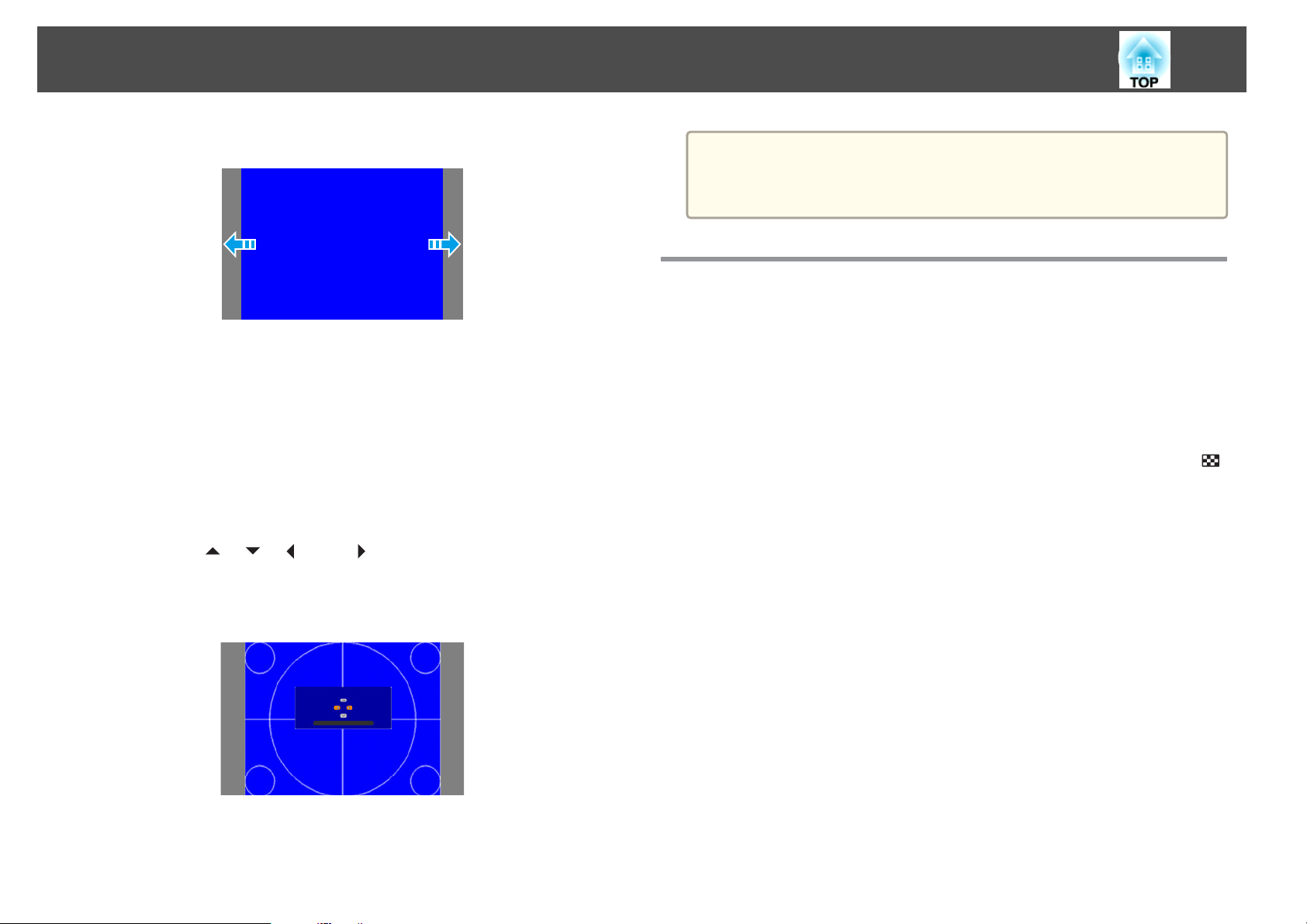
Adjusting the position of the image on the projected screen
You can adjust the position of the image if there are margins between the
edge of the image and the projected screen frame due to the Screen Type
setting.
Page 23
Installing the Projector
23
Example: When the Screen Type is set to 4:3 for EB-G6900WU
You can move the image to the left and right.
a
Press the [Menu] button while projecting.
s
"Using the Configuration Menu" p.84
Select Display from Extended.
b
c
Select Screen Position from Screen.
d
Use the [ ], [ ], [ ], and [ ] buttons to adjust the position of
the image.
You can check the current display position by using the background
test pattern.
The Screen Position cannot be adjusted in the following situations.
a
• If the Screen Type is set to 16:10 when using EB-G6900WU
• If the Screen Type is set to 4:3 when using EB-G6800
Displaying a Test Pattern
A test pattern can be displayed to adjust the projection status without
connecting video equipment.
The shape of a test pattern is according to the setting of Screen Type. Set
Screen Type first.
s
"Screen Settings" p.22
a
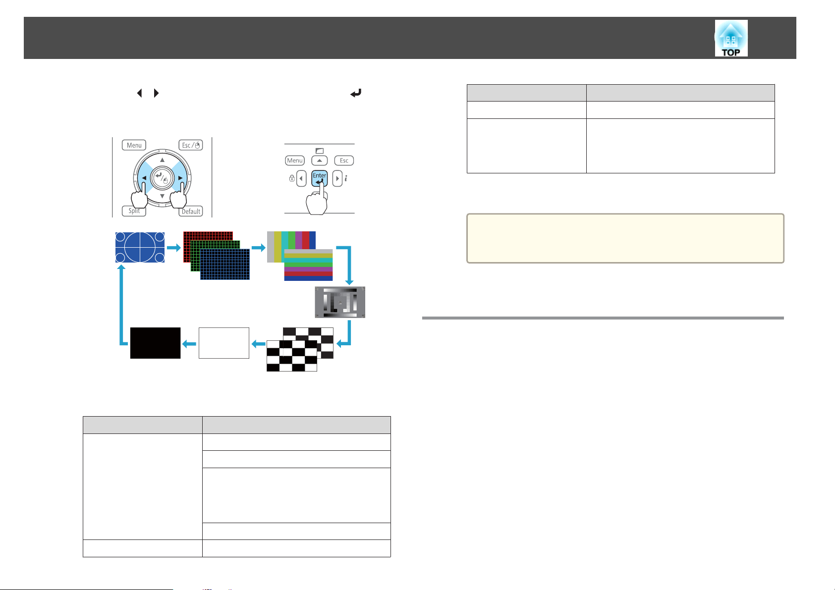
Press the [Test Pattern] button on the remote control or the [ ]
button on the control panel while projecting.
e
Press the [Menu] button to finish making settings.
Page 24
Installing the Projector
24
b
Press the [ ][ ] buttons on the remote control or the [ ] button
on the control panel to change the test pattern.
Using the remote control Using the control panel
The following image adjustments can be made while the test pattern
is being displayed.
Top Menu Name Sub Menu/Items
Settings
Extended
Except for custom settings of gamma
*1
*2 Except for Black Level
To set menu items that cannot be set while the test pattern is
a
Press the [Esc] button to close the test pattern.
being displayed or to fine-tune the projected image, project an
image from the connected device.
Geometric Correction s p.42
Multi-Projection
- Brightness Level
- Edge Blending
- Multi-screen s p.63
*2
s p.59
c
Adjusting the Position of the Projected Image (Lens Shift)
The lens can be shifted to adjust the position of the projected image, for
example, when the projector cannot be installed directly in front of the
screen.
Top Menu Name Sub Menu/Items
Image
Signal
Color Mode s p.49
Abs. Color Temp.
Advanced
*1
- Gamma
- RGB
- RGBCMY s p.53
Reset
Auto Setup
s p.54
a
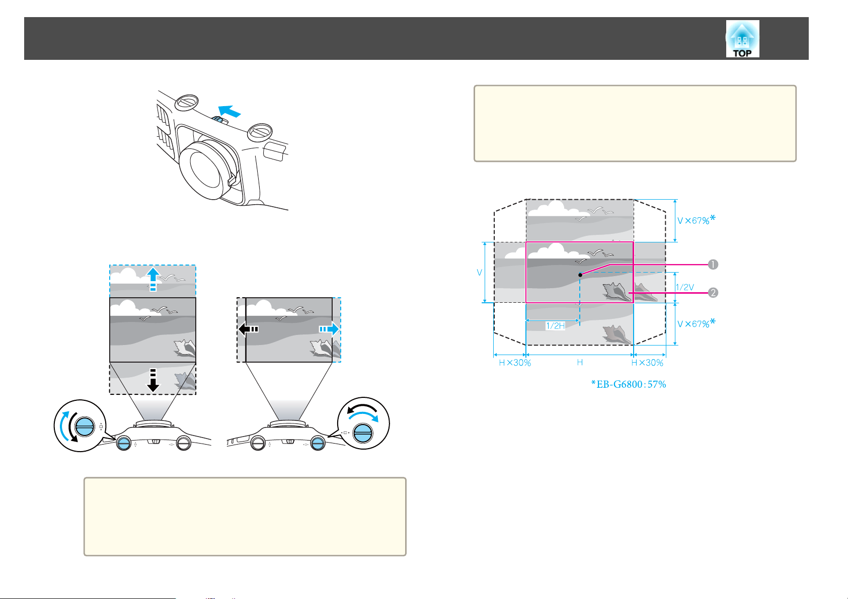
Release the lens shift dial lock.
Page 25
Installing the Projector
25
• We recommend setting the focus, zoom, and lens shift at least
a
The ranges within which the image can be moved are shown below.
30 minutes after you start the projection, because images are
not stable right after turning on the projector.
• The image will be clearest when both the vertical and
horizontal lens shift are set in the center.
b
Turn the vertical and horizontal lens shift dials on the projector to
adjust the position of the projected image.
Attention
When adjusting the image height with the vertical lens shift dial, adjust
by moving the image from the bottom to the top. If it is adjusted from
the top to the bottom, the image position may move down slightly
after adjusting.
c
Center of lens
A
Projected image when lens shift is set in the center
B
The position of the projected image cannot be moved to both the
horizontal and vertical maximum values.
When you have finished making adjustments, lock the lens shift
dial lock.
Page 26
Installing the Projector
26
When using the short throw zoom lens ELPLU01
Adjusting the Image Size
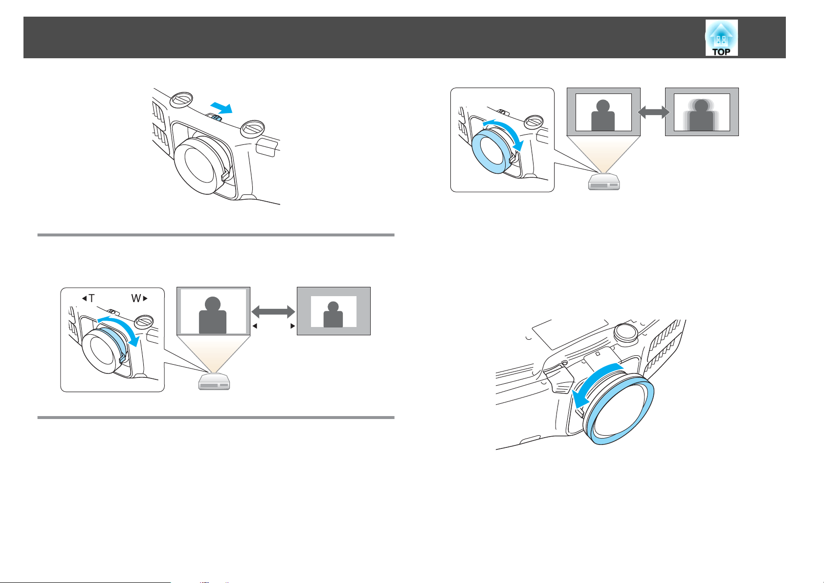
Turn the zoom ring to adjust the size of the projected image.
W T
Correcting the Focus
You can correct the focus using the focus ring.
Follow the steps below to adjust the focus when the lens is shifted up,
down, left, or right using the lens shift function.
a
Turn the distortion ring anti-clockwise until it cannot go any
further.
Focus the image around the axis of the lens using the focus ring.
b
Example: When the lens shift is turned all the way down.
Page 27
Installing the Projector
27
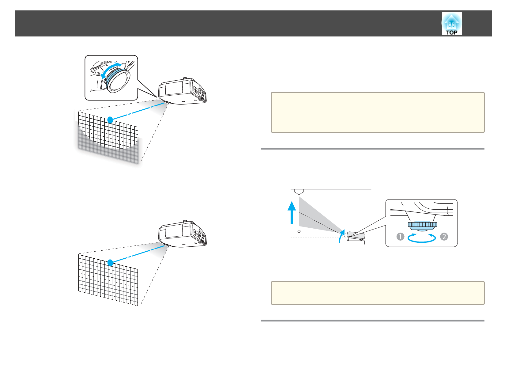
c
Correct screen distortion using the distortion ring.
When correcting distortion, the area around the edges of the image
is also focused.
d
Turn the focus ring to focus the entire screen.
If the area around the lens axis is out of focus, fine-tune by turning
the distortion ring.
When using the short throw zoom lens ELPLU01, set Lens Type to
a
ELPLU01 from the Configuration menu so that keystone correction is
performed correctly.
s Extended - Operation - Lens Type p.91
Adjusting the Image Position
Extend or retract the front foot to make adjustments. You can adjust the
position of the image by tilting the projector up to 10 degrees.
Extend the front foot.
A
Retract the front foot.
B
The larger the angle of tilt, the harder it becomes to focus. Install the
a
projector so that it only needs to be tilted at a small angle.
Adjusting the Horizontal Tilt
Extend and retract the rear feet to adjust the projector's horizontal tilt.
Page 28
Installing the Projector
28
Set the projector ID
Extend the rear foot.
A
Retract the rear foot.
B
Attention
The rear feet can be attached and removed. Note that the feet will detach if
they are extended more than 10 mm.
ID Settings
When an ID is set for the projector and the remote control, you can use
the remote control to operate only the projector with a matching ID. This
is very useful when managing multiple projectors.
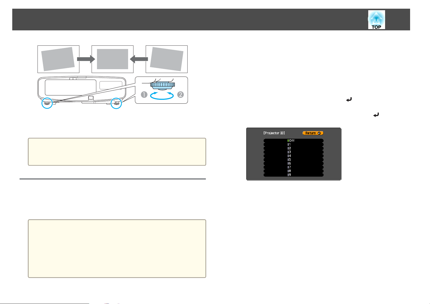
a
b
c
d
e
Press the [Menu] button while projecting.
s
"Using the Configuration Menu" p.84
Select Multi-Projection from Extended.
Select Projector ID, and then press the [ ] button.
Select the ID you want to set, and then press the [ ] button.
Press the [Menu] button to close the configuration menu.
a
• Operation using the remote control is possible only for projectors
that are within the operating range of the remote control.
s "Remote control operating range" p.15
• When Remote Control Type is set to Simple from Operation in the
configuration menu, you cannot set the remote control ID.
s p.91
• IDs are ignored when the projector ID is set to Off or the remote
control ID is set to 0.
Page 29
Installing the Projector
29
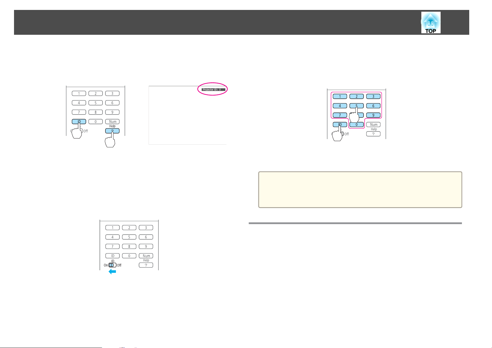
Checking the Projector ID
During projection, press the [Help] button while holding the [ID] button.
Remote control
When you press the buttons, the current Projector ID is displayed on the
projection screen. It disappears in about three seconds.
Setting the remote control ID
Set the remote control [ID] switch to On.
a
b
Once this setting has been made, the projector that can be operated by the
remote control is limited.
While holding the [ID] button, press a number button to select a
number to match the ID of the projector you want to operate.
s
"Checking the Projector ID" p.29
Remote control
The remote control ID setting is saved in the remote control. Even if
a
the remote control batteries are removed to replace them and so on,
the stored ID setting is retained. However, if the batteries are left out
for a long time, it is reset to the default value (ID0).
Setting the Time
You can set the time for the projector. The set time is used for the schedule
function.
s
"Scheduling Function" p.75
Page 30
Installing the Projector
30
a
a
b
c
d
• When you turn on the projector for the first time, the message "Do
you want to set the time?" is displayed. When you select Yes, the
screen from step 4 is displayed.
• When Time/Schedule Protection is set to On in Password
Protection, settings related to the date and time cannot be changed.
You can make changes after setting Time/Schedule Protection to
Off.
"Managing Users (Password Protection)" p.78
s
Press the [Menu] button while projecting.
s
"Using the Configuration Menu" p.84
Select Operation from Extended.
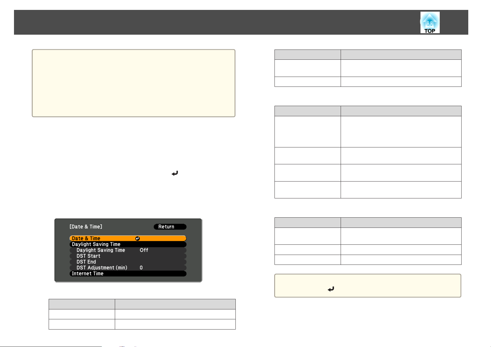
Select Date & Time, and then press the [ ] button.
Make settings for the date and time.
Use the soft keyboard to enter the date and time.
s
"Soft keyboard operations" p.96
Submenu Function
Time Difference (UTC)
Set
Daylight Saving Time
Submenu Function
Daylight Saving Time
DST Start
DST End
Set
Internet Time
Submenu Function
Internet Time
Set the time difference from Coordinated
Universal Time.
The settings made in Date & Time are applied.
Set whether or not (On/Off) to activate the
daylight saving time.DST Adjustment (min)
adjusts the time difference between the standard
time and the daylight saving time.
Set the date and time to start the daylight saving
time.
Set the date and time to end the daylight saving
time.
The settings made in Daylight Saving Time are
applied.
Set to On to update the time automatically through
an Internet time server.
Date & Time
Submenu Function
Date
Time
Set today's date.
Set the current time.
e
Internet Time Server
Set
When changing settings, make sure you select Set, and then
a
Press the [Menu] button to finish making settings.
press the [
Input the IP address for an Internet time server.
The settings made in Internet Time are applied.
] button.
Page 31

Connecting Equipment
The port name, location, and connector orientation differ depending on the source being connected.
Connecting a Computer
To project images from a computer, connect the computer using one of the following methods.
When using the supplied computer cable
A
Connect the computer's display output port to the projector's Computer port.
You can output audio from the projector's Audio Out port by connecting the audio output port on the computer to the projector's Audio1 port using a commercially available audio
cable.
When using a commercially available 5BNC cable
B
Connect the computer's display output port to the projector's BNC port.
You can output audio from the projector's Audio Out port by connecting the audio output port on the computer to the projector's Audio2 port using a commercially available audio
cable.
When using a commercially available HDMI cable
C
Connect the HDMI port on the computer to the projector's HDMI port.
You can send the computer's audio with the projected image.
When using a commercially available DisplayPort cable
D
Connect the computer's DisplayPort to the projector's DisplayPort.
You can send the computer's audio with the projected image.
31
Page 32

Connecting Equipment
32
Computer
a
4
Audio1
BNC
Audio2
HDMIOUTHDMI
4
DisplayPort DisplayPortOUT
• Change the audio output from Audio Settings.
s Extended - A/V Settings - Audio Settings p.91
• If audio is not sent using an HDMI or DisplayPort cable, connect a commercially available audio cable to the Audio3 port to send the audio. Set HDMI Audio
Output or DisplayPort Audio Output to Audio3.
s Extended - A/V Settings - Audio Settings - HDMI Audio Output, DisplayPort Audio Output p.91
• Some commercially available DisplayPort cables come with a lock. When removing the cable, press the button on the cable's connector section and pull out the
cable.
Page 33

Connecting Equipment
Connecting Image Sources
To project images from DVD players or VHS video and so on, connect to the projector using one of the following methods.
When using a commercially available video cable
A
Connect the video output port on the image source to the projector's Video port.
You can output audio from the projector's Audio Out port by connecting the audio output port on the image source to the projector's Audio-L/R port using a commercially available
audio cable.
When using a commercially available S-video cable
B
Connect the S-video output port on the image source to the projector's S-Video port.
You can output audio from the projector's Audio Out port by connecting the audio output port on the image source to the projector's Audio-L/R port using a commercially available
audio cable.
When using an optional component video cable (D-sub/component converter)
C
s "Optional Accessories" p.148
Connect the component output port on the image source to the projector's Computer port.
You can output audio from the projector's Audio Out port by connecting the audio output port on the video equipment to the projector's Audio1 port using a commercially available
audio cable.
When using a commercially available component video cable (RCA) and a BNC/RCA adapter
D
Connect the component output port on the video equipment to the projector's BNC port (R/Cr/Pr, G/Y, B/Cb/Pb).
You can output audio from the projector's Audio Out port by connecting the audio output port on the video equipment to the projector's Audio2 port using a commercially available
audio cable.
When using a commercially available HDMI cable
E
Connect the HDMI port on the image source to the projector's HDMI port.
You can send the image source's audio with the projected image.
When using a commercially available BNC video cable (EB-G6900WU only)
F
Connect the SDI port on the image source to the projector's SDI port.
Audio output is not supported.
33
Page 34

Connecting Equipment
4
34
Video
Video
AUDIOOUT(L,R)
Audio-L/R
S-Video
56
S-Video
Audio-L/R
Computer
Audio1
AUDIOOUT(L,R)
Y
Cb/Pb
Cr/Pr
AUDIOOUT
4
BNC(R/Cr/Pr,G/Y,B/Cb/Pb)
Audio2
5
HDMI
6
SDI
Y
Cb/Pb
Cr/Pr
AUDIOOUT
HDMIOUT
SDIOUT
Page 35

Connecting Equipment
Attention
• If the input source is on when you connect it to the projector, it could cause a malfunction.
• If the orientation or shape of the plug differs, do not try to force it in. The device could be damaged or could malfunction.
• Change the audio output from Audio Settings.
a
s Extended - A/V Settings - Audio Settings p.91
• If audio is not sent using an HDMI cable, connect a commercially available audio cable to the Audio3 port to send the audio. Set HDMI Audio Output to
Audio3.
s Extended - A/V Settings - Audio Settings - HDMI Audio Output p.91
• If the source you want to connect to has an unusually shaped port, use the cable supplied with the device or an optional cable to connect to the projector.
• When using a commercially available 2RCA(L/R)/stereo mini-pin audio cable, make sure it is labeled "No resistance".
Connecting External Equipment
35
You can output images and audio by connecting an external monitor or speaker.
When outputting images to an external monitor
A
Connect the external monitor to the projector's Monitor Out port using the cable supplied with the external monitor.
When outputting audio to an external speaker
B
Connect the external speaker to the projector's Audio Out port using a commercially available audio cable.
Page 36

Connecting Equipment
Make the following settings to output image and audio even when the projector is in standby mode.
a
Set Standby Mode to Communication On.
s Extended - Standby Mode p.91
Set A/V Output to Always On.
s Extended - A/V Settings - A/V Output p.91
36
MonitorOut D-Sub
AudioOut AudioIN
Connecting a LAN Cable
Connect a LAN port on network hubs or other equipment to the projector's LAN port with a commercially available 100BASE-TX or 10BASE-T LAN
cable.
By connecting a computer to the projector over a network, you can check the status of the projector.
LAN
Page 37

Connecting Equipment
To prevent malfunctions, use a category 5 or higher shielded LAN cable.
a
Connecting an HDBaseT Transmitter
Connect the optional HDBaseT Transmitter with a commercially available 100BASE-TX LAN cable.
s
"Optional Accessories" p.148
HDBaseT
37
a
• Make sure you read the User's Guide supplied with the HDBaseT Transmitter carefully before use.
• Use a category 5e or category 6 shielded LAN cable.
• When connecting or disconnecting the LAN cable, make sure you turn off the power for the projector and the HDBaseT Transmitter.
• When performing Ethernet communication or serial communication, or when using the wired remote control via HDBaseT port, set Control Communications
to On from the Configuration menu.
s Extended - HDBaseT - Control Communications p.91
Note that when Control Communications is set to On, the projector's LAN port, RS-232C port, and Remote port are disabled.
Page 38

Connecting Equipment
Attaching the Cable Cover
By attaching the cable cover, you can hide the connected cables giving a
nice, clean finish to the projector installation. (The illustrations are of a
projector installed on a ceiling.)
Attaching
38
a
b
Bundle the cables together with a commercially available tie.
Insert the tabs on the cable cover into the two slots on the back
of the projector.
c
Tighten the two screws on the cable cover. (You can tighten the
screws with your fingers.)
Page 39

Basic Usage
This chapter explains how to project and adjust images.
Page 40

Projecting Images
40
Automatically Detect Input Signals and Change the Projected Image (Source Search)
Press the [Search] button on the remote control or the [Source Search]
button on the control panel to project images from the port currently
receiving an image.
Using the remote control Using the control panel
The following screen is displayed while no image signals are input.
a
*EB-G6900WU only
When two or more image sources are connected, press the [Search] button
on the remote control or the [Source Search] button on the control panel
until the target image is projected.
When your video equipment is connected, start playback before beginning
this operation.
Page 41

Projecting Images
41
Switching to the Target Image by Remote Control
You can change directly to the target image by pressing the following
buttons on the remote control.
The input ports for each button are shown below.
Remote control
Input Port
• Press the [Volume] button on the remote control to adjust the volume.
a
] Decreases the volume.
[
b
[
] Increases the volume.
Remote control
• Adjust the volume from the Configuration menu.
s
Settings - Volume p.90
Caution
Do not start at high volume.
A sudden excessive volume may cause loss of hearing. Always lower the volume
before powering off, so that you can power on and then gradually increase the
volume.
EB-G6900WU only
F
Adjusting the Volume
You can adjust the volume for audio output from the Audio Out port using
one of the following methods.
When the source is SDI, no audio is output.
a
Page 42

Adjusting Projected Images
42
Correcting Distortion in the Projected Image
You can correct keystone distortion in projected images using one of the
following methods.
• H/V-Keystone
Manually correct distortion in the horizontal and vertical directions
independently.
s
"H/V-Keystone" p.43
• Quick Corner
Manually correct the four corners independently.
s
"Quick Corner" p.43
• Curved Surface
Manually correct distortion that occurs when projecting on a curved
surface, and adjust the amount of expansion and contraction.
s
"Curved Surface" p.44
• Point Correction
Corrects slight distortion which occurs partially, or adjusts the image
position in an overlapping area when projecting from multiple projectors.
s
"Point Correction" p.57
• Corner Wall
Manually correct distortion that occurs when projecting on a surface with
right angles, such as a square pillar or the corner of a room, and adjust
the amount of expansion and contraction.
s
"Corner Wall" p.47
Page 43

Adjusting Projected Images
43
• By pressing the [ ] button on the control panel, you can perform
a
H/V-Keystone
Manually correct distortion in the horizontal and vertical directions
independently. Distortion can be corrected when the angle of vertical and
horizontal tilt of the projector is up to 30 degrees (19 degrees when using
the short throw zoom lens ELPLU01) against the screen.
the selected adjustment method directly.
• You cannot combine multiple adjustment methods. However, you
can use Point Correction after performing Curved Surface or Corner
Wall.
Press the [Menu] button while projecting.
a
b
Select Geometric Correction from Settings.
c
Select H/V-Keystone, and then press the [ ] button.
If the message "If this setting is changed, the image may be
distorted." is displayed, press the [
] button.
V-Keystone
H-Keystone
a
e
Quick Corner
When you are done, press the [Menu] button to exit the correction
menu.
When you correct keystone distortion, the projected image may
be reduced.
d
Use the [ ][ ] buttons to select the correction method, and
then use the [
][ ] buttons to make the corrections.
This allows you to manually correct each of the four corners of the
projected image separately.
Press the [Menu] button while projecting.
a
b
Select Geometric Correction from Settings.
c
Select Quick Corner, and then press the [ ] button.
If the message "If this setting is changed, the image may be
distorted." is displayed, press the [
] button.
Page 44

Adjusting Projected Images
44
d
Use the [ ], [ ], [ ], and [ ] buttons to select the corner you
want to adjust, and then press the [
If the [Esc] button is pressed for at least 2 seconds, the confirm
a
default reset screen is displayed.
Select Yes to reset the result of Quick Corner corrections.
] button.
f
g
Curved Surface
Repeat procedures 4 and 5 as needed to adjust any remaining
corners.
When you are done, press the [Menu] button to exit the correction
menu.
e
Use the [ ], [ ], [ ], and [ ] buttons to correct the position of
the corner.
When you press the [
allows you to select the area to be corrected is displayed.
If the message "Cannot adjust any further." is displayed while
adjusting, you cannot adjust the shape any further in the direction
indicated by the gray triangle.
] button, the screen shown in step 4 that
a
a
b
• Project from the front with lens shift in the center.
s "Adjusting the Position of the Projected Image (Lens Shift)"
p.24
• Project onto an arc surface with the same radius.
• If a large amount of adjustment is performed, the focus may not be
uniform even after making adjustments.
Press the [Menu] button while projecting.
Select Geometric Correction from Settings.
Page 45

Adjusting Projected Images
45
c
d
e
Select Curved Surface, and then press the [ ] button.
If the message "If this setting is changed, the image may be
distorted." is displayed, press the [
Select Correct Shape, and then press the [ ] button.
Use the [ ], [ ], [ ], and [ ] buttons to select the area you
want to adjust, and then press the [
] button.
] button.
f
If the [Esc] button is pressed for at least 2 seconds, the confirm
a
Use the [ ], [ ], [ ], and [ ] buttons to adjust the shape.
If the triangle in the direction you are adjusting the shape turns gray,
as shown in the screenshot below, you cannot adjust the shape any
further in that direction.
default reset screen is displayed.
Select Yes to reset the result of Curved Surface.
When selecting a corner, you can adjust the two sides next to the
corner.
g
Press the [Esc] button to return to the previous screen.
Page 46

Adjusting Projected Images
46
h
i
j
Repeat procedures from 5 to 7 as needed to adjust any remaining
parts.
If the image expands and contracts, go to the next step and adjust
the linearity.
Press the [Esc] button to return to the screen in step 4. Select
Horizontal Linearity or Vertical Linearity, and then press the [
button.
Select Horizontal Linearity to adjust the horizontal expansion or
contraction, and select Vertical Linearity to adjust the vertical
expansion or contraction.
Select the standard line for the adjustments, and then press the
[
] button.
]
When the [ ] is pressed
Selecting the Horizontal Linearity Selecting the Vertical Linearity
l
When you are done, press the [Menu] button to exit the correction
menu.
k
Use the [
and the [
then press the [
The selected standard line is displayed in flashing red and white.
Adjust the linearity.
When the [
Selecting the Horizontal Linearity Selecting the Vertical Linearity
][ ] buttons when selecting the Horizontal Linearity,
][ ] buttons when selecting the Vertical Linearity, and
] button.
] is pressed
a
You can fine tune the results of Curved Surface using Point
Correction. Change Geometric Correction to Point Correction, and
then make adjustments after selecting Keep the current geometric
correction settings.
s "Point Correction" p.57
Page 47

Adjusting Projected Images
Corner Wall
• Project onto a surface with a right angle.
a
• If a large amount of adjustment is performed, the focus may not be
uniform even after making adjustments.
• You may not be able to adjust Corner Wall correctly when using the
short throw zoom lens ELPLU01.
Press the [Menu] button while projecting.
a
b
Select Geometric Correction from Settings.
47
Select Horizontal Corner.
When the surfaces line up vertically
c
d
e
Select Corner Wall, and then press the [ ] button.
If the message "If this setting is changed, the image may be
distorted." is displayed, press the [
Select Corner Type, and then press the [ ] button.
To fit the projected image to the projection position, select
Horizontal Corner or Vertical Corner, and then press the [
button.
When the surfaces line up horizontally
] button.
Select Vertical Corner.
From here on, steps are explained using Horizontal Corner as an
example.
f
]
g
Press the [Esc] button to return to the screen in step 4. Select
Correct Shape, and then press the [
Adjust the position of the projector and the lens shift so that the
line in the center of the screen matches the corner (the point
where the two surfaces meet).
s
"Adjusting the Position of the Projected Image (Lens Shift)"
p.24
] button.
Page 48

Adjusting Projected Images
Each time you press the [ ] button, you can show or hide the
h
a
Use the [ ], [ ], [ ], and [ ] buttons to select the area you
want to adjust, and then press the [
image and the grid.
] button.
48
When selecting Vertical Corner:
Adjust the left and right based on the point nearest to the vertical
line in the center of the screen.
If the [Esc] button is pressed for at least 2 seconds, the confirm
a
default reset screen is displayed.
Select Yes to reset the result of Corner Wall.
Adjustment tips
When selecting Horizontal Corner:
Adjust the upper area based on the lowest point (indicated by a blue
arrow).
Adjust the lower area based on the highest point (indicated by a red
arrow).
i
j
k
Use the [ ][ ][ ][ ] buttons to adjust the shape.
If the message "Cannot adjust any further." is displayed while
adjusting, you cannot adjust the shape any further in the direction
indicated by the gray triangle.
Repeat procedures 8 and 9 as needed to adjust any remaining
parts.
If the image expands and contracts, go to the next step and adjust
the linearity.
Press the [Esc] button to return to the screen in step 4. Select
Linearity, and then press the [
] button.
Page 49

Adjusting Projected Images
a
49
You can fine tune the results of Corner Wall using Point Correction.
Change Geometric Correction to Point Correction, and then make
adjustments after selecting Keep the current geometric correction
settings.
s "Point Correction" p.57
l
m
Use the [ ][ ] buttons to adjust the linearity.
When the [
When selecting Horizontal Corner When selecting Vertical Corner
When the [ ] is pressed
When selecting Horizontal Corner When selecting Vertical Corner
When you are done, press the [Menu] button to exit the correction
menu.
] is pressed
Selecting the Projection Quality (Selecting Color Mode)
You can easily obtain the optimum image quality simply by selecting the
setting that best corresponds to your surroundings when projecting. The
brightness of the image varies depending on the mode selected.
Mode Application
Dynamic
Presentation
Theatre
*1
Photo
*2
Sports
sRGB
DICOM SIM
*1
Ideal for use in a bright room. This is the brightest
mode.
Ideal for making presentations using color materials
in a bright room.
Ideal for watching films in a dark room. Gives
images a natural tone.
Ideal for projecting still pictures, such as photos, in
a bright room. The images are vivid and brought
into contrast.
Ideal for watching TV programmes in a bright
room. The images are vivid and brought to life.
Ideal for images that conform to the
standard.
Ideal for projecting X-ray photographs and other
medical images. This produces images with clear
shadows. The projector is not a medical device and
cannot be used for medical diagnosis.
sRGBg color
Page 50

Adjusting Projected Images
50
Mode Application
Multi-Projection
*1 This can only be selected when inputting RGB signals.
*2 This can only be selected when inputting component video signals, or when
the source is Video or S-Video.
Each time you press the [Color Mode] button, the Color Mode name is
displayed on the screen and the Color Mode changes.
Remote control
You can set Color Mode from the Configuration menu.
a
s Image - Color Mode p.87
Ideal for projecting from multiple projectors.
Minimize the color tone difference between each
projected image.
When projecting 3D images, set 3D Images to On from the Configuration
menu.
s
Signal - 3D Setup - 3D Images p.88
The following color modes are available when projecting 3D images. When
projecting using the optional polarizers (ELPPL01), you can view images at
their optimal color tint.
• 3D Dynamic
• 3D Presentation
• 3D Theatre
• 3D Multi-Projection
This projector arranges the direction of polarizing projection for R
a
(red), G (green), and B (blue). It is not necessary to inverse left and
right eye G (green) image signals.
Changing the Aspect Ratio of the Projected Image
You can change the Aspect Ratiog of the projected image to suit the type,
the ratio of height and width, and the resolution of the input signals.
Available aspect modes vary depending on the Screen Type currently set.
Projecting 3D images
By using two projectors, you can project passive 3D images. You need the
following optional items to project and view 3D images. Make sure you
read the notes in the user's guides supplied with the optional items.
• Polarizer (ELPPL01)
• Passive 3D Glasses (ELPGS02A/ELPGS02B)
s
"Optional Accessories" p.148
a
Set the Screen Type before changing the aspect ratio.
s "Screen Settings" p.22
Page 51

Adjusting Projected Images
51
Changing methods
Each time you press the [Aspect] button on the remote control, the aspect
mode name is displayed on the screen and the aspect ratio changes.
Remote control
Aspect Mode Explanation
Auto
Normal
4:3
16:9
Full
Zoom
Projects in an appropriate aspect ratio based on
information from the signal being input.
Projects while retaining the aspect ratio of the input image.
Projects at an aspect ratio of 4:3.
Projects at an aspect ratio of 16:9.
Projects at the full size of the projected screen.
Projects by enlarging the input image to the full width of
the projected screen while retaining the aspect ratio. Areas
that exceed the edges of the projected screen are not
projected.
• You can also set the aspect ratio from the Configuration menu.
a
s Signal - Aspect p.88
• If parts of the computer image are missing, set the Resolution
setting to Wide or Normal from the Configuration menu, according
to the resolution of the computer.
s Signal - Resolution p.88
The aspect mode changes as shown in the tables below.
The following colors in screen images in the tables indicate areas that are
not displayed.
: The area where the image is not displayed depending on the screen
type setting.
: The area where the image is not displayed depending on the aspect
mode setting.
EB-G6900WU
Screen type setting: 16:10
Aspect Ratio of Input Signal
16:10 16:9 4:3
Auto or Normal
Native
Projects to the center of the projected screen at the
resolution of the input image. Areas that exceed the edges
of the projected screen are not projected.
16:9
Full
Page 52

Adjusting Projected Images
52
Aspect Ratio of Input Signal
16:10 16:9 4:3
Zoom
*
Native
The image may differ depending on the resolution of the input signal.
*
Screen type setting: 16:9
Aspect Ratio of Input Signal
16:10 16:9 4:3
Auto or Normal
Full
Auto or Normal
4:3
16:9
Native
Only computer images and images from the HDMI port/HDBaseT port. The
*
image may differ depending on the resolution of the input signal.
EB-G6800
Aspect Ratio of Input Signal
16:10 16:9 4:3
*
Zoom
*
Native
* The image may differ depending on the resolution of the input signal.
Screen type setting: 4:3
Screen type setting: 4:3
Aspect Ratio of Input Signal
16:10 16:9 4:3
Auto or Normal
4:3
16:9
Page 53

Adjusting Projected Images
53
Aspect Ratio of Input Signal
16:10 16:9 4:3
*
Native
* Only computer images and images from the HDMI port/HDBaseT port. The
image may differ depending on the resolution of the input signal.
Screen type setting: 16:9
Aspect Ratio of Input Signal
16:10 16:9 4:3
Auto or Normal
Full
Zoom
*
Native
The image may differ depending on the resolution of the input signal.
*
Screen type setting: 16:10
Aspect Ratio of Input Signal
Aspect Ratio of Input Signal
16:10 16:9 4:3
16:9
Full
Zoom
*
Native
* The image may differ depending on the resolution of the input signal.
Adjusting the Image
Hue, Saturation, and Brightness Adjustment
The Hue, Saturation, and Brightness for each of the R (red), G (green), B
(blue), C (cyan), M (magenta) and Y (yellow) color components can be
adjusted.
Make settings from the configuration menu.
s
Image - Advanced - RGBCMY p.87
Auto or Normal
16:10 16:9 4:3
Page 54

Adjusting Projected Images
54
larger value is selected, you can reduce the overall brightness of the image
to make the image sharper.
If you select DICOM SIM from Color Mode on the Image menu, select the
adjustment value according to the projection size.
• If the projection size is 120 inches or less, select a large value.
• If the projection size is 120 inches or more, select a small value.
Medical images may not be reproduced correctly according to your
a
settings and screen specifications.
Gamma Adjustment
Adjusts differences in the coloring for the projected image that occurs
depending on the connected device.
Make settings from the configuration menu.
s
Image - Advanced - Gamma p.87
Select and adjust the correction value
s
Image - Advanced - Gamma p.87
When a smaller value is selected, the dark areas of images become brighter,
but the color saturation for lighter areas may become weaker. When a
Adjust while viewing the image
Image - Advanced - Gamma - Customized - Adjust it from the image
s
p.87
Move the cursor on the projected image to the part where you want to
change the brightness, then press the [
to adjust the value.
] button. Use the [ ][ ] buttons
Page 55

Adjusting Projected Images
Adjust using the gamma adjustment graph
Image - Advanced - Gamma - Customized - Adjust it from the graph
s
p.87
Adjust while looking at the gamma adjustment graph.
55
Make settings from the configuration menu.
s
Signal - Frame Interpolation p.88
You can select the level of interpolation: Low, Normal or High. Set to Off
if noise occurs after setting them.
Frame Interpolation (EB-G6900WU only)
The current and previous frames are used to create intermediate frames,
interpolating to produce smooth-moving images. You can resolve clumsymoving images, such as frame skipping when projecting a fast moving
image.
Page 56

Useful Functions
This chapter explains useful tips for giving presentations, and the Security functions.
Page 57

Multi-Projection Function
57
When projecting to a wide screen from multiple projectors, you can adjust
the difference of brightness and color tone between each projected image to
create a seamless screen.
There are two general methods of projecting from multiple projectors.
U Projecting different images from each projector, and creating a seamless screen
V Projecting the same image from each projector, using the Scale function to
project a large image
Follow the steps below.
1. Set an ID for the projector and the remote control s p.28
2. Adjust the position of the projected image s p.57
3. Checking the Color Mode
4. Adjust the edges of the images (edge blending) s p.59
5. Adjusting to match colors
Adjusting the Position of the Projected Image
Adjust the position of the projected image, starting from the adjustments
that have larger corrections.
1. Projector's position (angle) s p.20
2. Lens shift/Zoom s p.24
3. Geometric Correction
• Quick Corner s p.43
• Point Correction
• We recommend setting the focus, zoom, and lens shift at least 30
a
minutes after you start the projection, because images are not stable
right after turning on the projector.
• The Test Pattern can be displayed to adjust the projection status
without connecting video equipment. s p.23
• When projecting from multiple projectors, the correction is easier if
you use the image in dot by dot format, that can be displayed
without being enlarged or reduced.
s
p.57
Here we will take U as an example.
V
The steps for
position of the projected image.
are the same, but use the Scale function to adjust the
s
Point Correction
Corrects slight distortion which occurs partially, or adjusts the image
position in an overlapping areas.
p.64
Page 58

Multi-Projection Function
Divides the projected image by the grid and corrects the distortion by
moving the point of intersection from side to side and up and down.
58
a
b
c
d
Press the [Menu] button while projecting.
Select Geometric Correction from Settings.
Select Point Correction, and then press the [ ] button.
If the message "If this setting is changed, the image may be
distorted." is displayed, press the [
When changing from Curved Surface or Corner Wall to Point
a
Select Point Correction, and then press the [ ] button.
Correction, the screen displaying the adjustment method is
displayed.
Keep the current geometric correction settings: Use Point
Correction to fine tune images adjusted using Curved Surface or
Corner Wall.
Reset the geometric correction settings: Reset adjustments
made to images using Curved Surface or Corner Wall, and then
perform adjustment using Point Correction.
] button.
e
f
Point Correction: Performs point correction.
Pattern Color: Select the color of the grid when performing
corrections.
Reset: Resets all corrections for Point Correction to their default
values.
Select the number of grid lines (3x3, 5x5, or 9x9), and then press
the [
Use the [ ], [ ], [ ], and [ ] buttons to move to the point you
want to correct, and then press the [
] button.
] button.
g
Use the [ ], [ ], [ ], and [ ] buttons to correct distortion.
Page 59

Multi-Projection Function
59
Adjusting the brightness of the lamp
Before performing edge blending, adjust so that the lamp brightness is the
same for each projector.
Adjust so that all projectors are the same brightness as the darkest lamp.
You can adjust the brightness in five levels.
To continue to correct another point, press the [Esc] button to
return to the previous screen, and then repeat steps 6 and 7.
Each time you press the [ ] button, you can show or hide the
h
a
When you are done, press the [Menu] button to exit the correction
menu.
image and the grid.
Checking the Color Mode
Set the Color Mode to Multi-Projection (or 3D Multi-Projection for 3D
s
images).
p.49
Adjust the Edges of the Images (Edge Blending)
When multiple projectors are lined up and projecting images, you can
create a seamless screen.
• Set Power Consumption to Normal.
a
s Settings - Power Consumption p.90
• Even if you adjust the Brightness Level, the brightness of each lamp
may not match exactly.
Press the [Menu] button while projecting.
a
b
Select Multi-Projection from Extended.
c
Select Brightness Level, and then press the [ ] button.
d
Select 1 to 5 as the brightness.
e
Press the [Esc] button to return to the previous screen.
Performing edge blending
a
Press the [Menu] button while projecting.
s
"Using the Configuration Menu" p.84
b
c
Select Multi-Projection from Extended.
Select Edge Blending, and then press the [ ] button.
The following screen is displayed.
Page 60

Multi-Projection Function
Submenu Function
Guide Colors
You can select the combination of guide colors
from the three.
60
Submenu Function
Edge Blending
Top Edge/Bottom
Edge/Right Edge/Left
Edge
Black Level
Guide Display
Pattern Guide
Set to On to activate the edge blending function.
Set to Off when not projecting from multiple
projectors.
Blending: Set to On to activate the edge blending
function towards where you are setting, and the
brend range will be shaded.
Blend Range: Adjusts the range to be shaded.
Adjustment is possible at the level of one pixel. The
maximum range is 45% of the resolution.
Adjusts the differences in brightness and tone for
areas where images overlap and areas where the
images do not overlap.
s "Black Level" p.61
Set to On to display the guide on the edge blending
setting range.
Set to On to display a guide to match the position of
the edge blending setting range.
d
e
f
g
Turn on Edge Blending.
(1)
Select Edge Blending, and then press the [
(2)
Select On, and then press the [
(3) Press the [Esc] button.
Set Guide Display to On.
(1)
Select Guide Display, and then press the [
(2)
Select On, and then press the [
(3) Press the [Esc] button.
If the guide is not clear, you can change the color of the guide
a
Set Pattern Guide to On.
(1)
(2)
(3) Press the [Esc] button.
Set Top Edge/Bottom Edge/Right Edge/Left Edge.
(1)
(2)
(3)
(4) Press the [Esc] button.
on Guide Colors.
Select Pattern Guide, and then press the [
Select On, and then press the [
Select Top Edge/Bottom Edge/Right Edge/Left Edge to set the edge
blending, and then press the [
Select Blending, and then press the [
Select On, and then press the [
] button.
] button.
] button.
] button.
] button.
] button.
] button.
] button.
] button.
Page 61

Multi-Projection Function
(5) In Blend Range, adjust the range to be shaded.
The value for when the overlapped range and the guide are in the same
position is the best.
(6) Press the [Esc] button.
(7) Set Guide Display and Pattern Guide to Off.
Black Level
When a black image is displayed, only areas where the images overlap
stands out. The black level function allows you to match the brightness and
tone for areas where the images do not overlap with areas where the images
overlap, to make the difference less noticeable.
a
61
• Black Level can only be adjusted correctly in images where two
images overlap.
• You cannot adjust the black level when a test pattern is displayed.
• If the Geometric Correction value is large, you may not be able to
adjust correctly.
• The brightness and tone may differ in areas where the images
overlap as well as in other areas even after performing black level
adjustment.
• If you change the Top Edge/Bottom Edge/Right Edge/Left Edge
setting, the Black Level is returned to its default value. s p.59
a
b
Select Multi-Projection from Extended. Select Edge Blending,
and then press the [
Select Black Level, and then press the [ ] button.
] button.
Page 62

Multi-Projection Function
62
The points where you want to set the range for black level
adjustment are displayed.
The points are displayed to match the Top Edge/Bottom Edge/Right
Edge/Left Edge settings.
The number of points displayed on one side differs depending on the
adjustment method selected in geometric correction.
Example: When Left Edge is set and Point Correction (5x5) is
selected
c
Select Area Correction, and then press the [ ] button.
d
e
Use the [ ], [ ], [ ], and [ ] buttons to select the point you
want to move, and then press the [
The selected point is displayed in orange.
Use the [ ][ ][ ][ ] buttons to move the point.
] button.
Page 63

Multi-Projection Function
63
f
g
To continue to move another point, press the [Esc] button to return
to step 4, and then repeat steps 4 and 5.
After moving all of the necessary points, press the [Esc] button to
return to step 4, and then press the [Esc] button again. When a
message is displayed, select Yes, and then press the [
The screen from step 3 is displayed.
Select Color Adjustment, and then press the [ ] button.
] button.
h
Adjust the brightness and tone for the areas that do not overlap
to match the areas that overlap.
To return Black Level to its default values, press the [Esc]
a
button to return to the screen from step 7, select Reset, and
then press the [
] button.
i
When you are done, press the [Menu] button to exit the correction
menu.
Adjusting to Match Colors
Follow the steps below to adjust the brightness of the projected image and
the color balance that was adjusted by performing edge blending.
The brightness and color may not be uniform even after making
a
adjustments.
Press the [Menu] button while projecting.
a
Page 64

Multi-Projection Function
64
b
c
Select Multi-Projection from Extended.
Select Multi-screen, and then press the [ ] button.
The following screen is displayed.
Adjustment Level: There are five levels from white, gray, and up to
black. Adjust each level individually.
Brightness Correct.: Adjust from black to white for each color tone.
Color Correct. (G/R): Adjust the color tone for green and red.
Color Correct. (B/Y): Adjust the color tone for blue and yellow.
Whenever the [ ] button is pressed, the screen changes
a
between the projected image and the adjustment screen.
h
When you are done, press the [Menu] button to exit the correction
menu.
Scaling an Image (Scale)
A section of the image is cropped and displayed. This allows you to create
one large image by combining images projected from multiple projectors.
a
Press the [Menu] button while an image is being projected.
s
"Using the Configuration Menu" p.84
Select Scale from Signal.
b
c
Set Scale to On.
(1)
Select Scale, and then press the [
(2)
Select On, and then press the [
(3) Press the [Esc] button to return to the previous screen.
Set Scale Mode.
] button.
] button.
d
(1)
Select Scale Mode, and then press the [
] button.
d
e
f
g
Select Adjustment Level, and then use the [ ][ ] buttons to set
the adjustment level.
Select Brightness Correct., and then use the [ ][ ] buttons to
adjust the brightness.
Select Color Correct. (G/R) or Color Correct. (B/Y), and then use
the [
Return to step 4 and adjust each level.
][ ] buttons to adjust the color.
Page 65

Multi-Projection Function
65
(2)
Select Zoom Display or Full Display, and then press the [
Zoom Display: Adjusts according to the image currently displayed.
Full Display: Adjusts according to the projector's panel size (the
maximum area in which an image can be displayed).
] button.
e
f
Adjust the scale.
Select the adjustment method with the [
adjust using the [
- +: Enlarges or reduces an image horizontally and vertically at the
same time.
Scale Vertically: Enlarges or reduces an image vertically.
Scale Horizontally: Enlarges or reduces an image horizontally.
Adjust the Image Display Range.
(1)
Select Image Display Range, and then press the [
(2)
Use the [
Adjust the coordinates and size of each image while viewing the screen.
(3) Press the [Menu] button to finish making settings.
][ ] buttons.
], [ ], [ ], and [ ] buttons to scroll the image.
][ ] buttons , then
] button.
(3) Press the [Esc] button to return to the previous screen.
Page 66

Projection Functions
66
Projecting Two Images Simultaneously (Split Screen)
You can simultaneously project images from two sources on the right and
left of the screen.
• The following input source combinations cannot be projected using
a
the split screen function.
Computer - BNC, S-Video - Video, HDMI - HDBaseT
• You cannot project the same input source on both sides (left and
right) of the screen.
Operating procedures
Projecting on a split screen
a
b
Press the [Split] button while projecting.
The currently selected input source is projected on the left of the
screen.
You can perform the same operations from the configuration
a
Press the [Menu] button.
The Split Screen Setup screen is displayed.
menu.
s Settings - Split Screen p.90
Remote control
c
Select Source, and then press the [ ] button.
Page 67

Projection Functions
67
d
Select each input source for Left and Right.
You can perform the same operations using the following
a
procedure.
s "Automatically Detect Input Signals and Change the
Projected Image (Source Search)" p.40
s "Switching to the Target Image by Remote Control" p.41
b
Select Swap Screens, and then press the [ ] button.
The projected images on the left and right are swapped.
Switching the left and right image sizes
Press the [Menu] button during split screen projection.
a
b
Select Screen Size, and then press the [ ] button.
c
Select the screen size you want to display, and then press the [ ]
button.
e
Select Execute, and then press the [ ] button.
To switch the source during split screen projection, start the
procedure from step 2.
Switching the left and right screens
Use the following procedure to switch the projected images displayed on
the left and right screens.
Press the [Menu] button during split screen projection.
a
Page 68

Projection Functions
68
The projected images will appear as shown below after setting the screen
size.
Equal Larger Left
Larger Right
c
Ending the split screen
Press the [Esc] button to end split screen.
The following steps can also be used to end the split screen.
• Press the [Split] button on the remote control.
• Select Exit Split Screen on the Split Screen Setup screen.
Select the audio you want to output, and then press the [ ]
button.
When you select Auto, audio is output for the largest screen.
If the screens are the same size, audio is output for the screen on the
left.
s
p.66
• You cannot enlarge both the left screen and right screen images at
a
Changing the audio
the same time.
• When one image is enlarged, the other image is reduced.
• Depending on the video signals that are input, the images on the left
and right may not appear to be the same size even if Equal is
set.
Press the [Menu] button during split screen projection.
a
b
Select Audio Source, and then press the [ ] button.
Restrictions during split screen projection
Operating restrictions
The following operations cannot be performed during split screen
projection.
• Setting the configuration menu
• E-Zoom
• Changing the aspect mode
• Using the [User1], [User2], or [User3] buttons on the remote control
• Help can be displayed only when image signals are not input or when
an error or warning notification is displayed.
Page 69

Projection Functions
69
• The user's logo is not displayed.
Restriction relating to images
• The default values for the Image menu are applied to the image on the
right screen. However, the settings for the image projected on the left
screen are applied to the image on the right screen for Color Mode,
Abs. Color Temp., and Advanced. Also, the Frame Interpolation
settings from the Signal menu are applied to the image projected on
the left screen.
• Auto Iris is not available.
s
Image - Auto Iris p.87
Hiding the Image and Sound Temporarily (A/V
Mute)
You can use this when you want to focus the audience's attention on what
you are saying, or if you do not want to show details such as when you are
changing between files during presentations from a computer.
A/V Mute is applied or released each time you press the [A/V Mute]
button.
Remote control
• When A/V Mute Release is set to A/V Mute from the configuration
a
menu, the following operations can still be performed without
releasing A/V mute.
s Extended - Operation - A/V Mute Release p.91
- Change the source with the change input buttons on the remote
control.
"Switching to the Target Image by Remote Control" p.41
s
- Control the projector from a computer using communication
commands.
s "Monitoring and Controlling" p.138
A/V mute is only released by pressing the [A/V Mute] button, or by
sending an A/V mute Off command.
• When projecting moving images, the images and sound continue to
be played back while A/V Mute is on. It is not possible to resume
projection from the point where A/V Mute was activated.
• You can select the screen displayed when the [A/V Mute] button is
pressed from the Configuration menu.
s Extended - Display - A/V Mute p.91
• The lamp is still lit during A/V Mute, so the lamp hours continue to
accumulate.
Page 70

Projection Functions
Freezing the Image (Freeze)
When Freeze is activated on moving images, the frozen image continues to
project on the screen, so you can project a moving image one frame at a
time like a still photo. Also, you can perform operations such as changing
between files during presentations from a computer without projecting any
images if the Freeze function is activated beforehand.
Each time you press the [Freeze] button, Freeze turns on or off.
Remote control
• Audio does not stop.
a
• When projecting moving images, the images continue to be played
back while the screen is frozen. It is not possible to resume
projection from the point where the screen was frozen.
• If the [Freeze] button is pressed while the Configuration menu or
the Help screen is displayed, the menu or the Help screen that is
displayed is closed.
• Freeze still works while E-Zoom is being used.
a
b
70
Start E-Zoom.
z
Press the [
Move the Cross ( ) to the area of the image that you want to
enlarge.
] button to display the Cross ( ).
Remote control
Remote control
Enlarging Part of the Image (E-Zoom)
This is useful when you want to expand images to see them in greater
detail, such as graphs and tables.
Page 71

Projection Functions
71
c
Enlarge.
Remote control
[z] button: Expands the area each time
it is pressed. You can expand quickly by
holding the button down.
[x] button: Reduces images that have
been enlarged.
[Esc] button: Cancels E-Zoom.
• During enlarged projection, press the [ ], [ ], [ ], or
a
Saving a User's Logo
You can save the image that is currently being projected as a User's Logo.
Once a User's Logo has been saved, the logo cannot be returned to the
a
factory default.
] buttons to scroll the image.
[
• E-Zoom is unavailable when Scale is set to On.
Signal - Scale p.88
s
c
d
• When User's Logo Protection from Password Protection is
a
When the message "Choose this image as the User's Logo?" is
displayed, select Yes.
a
Move the box to select the part of the image to use as the User's
Logo.
You can perform the same operations from the projector's control
panel.
set to On, a message is displayed and the User's Logo cannot
be changed. You can make changes after setting User's Logo
Protection to Off.
s "Managing Users (Password Protection)" p.78
• If User's Logo is selected when Geometric Correction, E-
Zoom or Aspect are being performed, the function currently
being performed is temporarily cancelled.
When you press the [ ] button, the screen size may change
depending on the signal to match the actual resolution of the
image signal.
Remote control
a
b
Project the image you want to save as the User's Logo, and then
press the [Menu] button.
s
"Using the Configuration Menu" p.84
Select User's Logo from Extended.
You can save at 400x300 dots in size.
a
Page 72

Projection Functions
72
e
f
g
When you press the [ ] button and the message "Select this
image?" is displayed, select Yes.
Select the zoom factor from the zoom setting screen.
When the message "Save this image as the User's Logo?" is
displayed, select Yes.
The image is saved. After the image has been saved, the message
"Completed." is displayed.
When a User's Logo is saved, the previous User's Logo is
a
erased.
Page 73

Memory Function
The settings for the image currently displayed are saved as a memory,
allowing you to load them when necessary. Settings for the following menu
items are saved in the memory.
Top Menu Submenu
Image
Signal
Settings
Extended
All setting items
3D Setup
Progressive
Frame Interpolation
Noise Reduction
Mosquito NR
Video Range
Scale
Overscan
Image Processing
Power Consumption
Multi-Projection
- Brightness Level
- Edge Blending
- Multi-screen
c
73
Select the function you want to perform, then press the [ ]
button.
You can only perform Load Memory and Save Memory when an
image is displayed.
Saving/Loading/Erasing the Memory
a
Press the [Menu] button while an image is being displayed.
s
"Using the Configuration Menu" p.84
Select Memory from Settings.
b
Page 74

Memory Function
Function Explanation
Load Memory
Loads the saved memory. When you select a
memory and press the [
applied to the current image are replaced with the
settings from the memory.
] button, the settings
74
Function Explanation
Rename Memory
Changes the memory name. Select the memory
name you want to change, and then press the [
button. Enter the memory name using the soft
keyboard.
s "Soft keyboard operations" p.96
When you have finished, move the cursor over
Finish, and then press the [
] button.
When a memory has already been saved, the memory name and its
color mode are displayed.
]
Save Memory
Erase Memory
The settings for the image currently displayed are
saved as a memory. When you select a memory
name and press the [
saved.
Erases the registered memory. When you select a
memory name and press the [
message is displayed. Select Yes, and then press the
[
] button to erase the selected memory. You can
erase all memories from Reset Memory.
s Reset - Reset Memory p.100
] button, the settings are
] button, a
a
If the mark on the left of the memory name is turned green, it
means the memory has already been registered. When you
select a registered memory, a message is displayed asking you to
confirm that you want to overwrite the memory. If you select
Yes, the previous settings are deleted and the current settings
are registered.
Page 75

Scheduling Function
You can schedule turning the projector power on/off and switching the
input source, as events in the schedule. Registered events are executed
automatically at the specified time on the specified dates or weekly.
Warning
Do not place flammable objects in front of the lens. If you set the schedule to
turn on the projector automatically, any flammable objects placed in front of
the lens could cause a fire.
Saving a Schedule
• You can set or adjust the date and time for the projector in Date &
a
Setting Methods
a
Time from the configuration menu.
s "Setting the Time" p.29
• When Time/Schedule Protection is set to On in Password
Protection, settings related to the scheduling function cannot be
changed. You can make changes after setting Time/Schedule
Protection to Off.
s "Managing Users (Password Protection)" p.78
Press the [Menu] button while projecting.
s
"Using the Configuration Menu" p.84
Select Schedule Settings from Extended.
b
c
Select Add New from Schedule.
d
Set the schedule.
Submenu Name Function
Event Settings
Date / Time Settings
Select an operation of the projector when the event
is executed. Select No Change for items that you do
not want to change when the event occurs.
You can set the following item operations.
• Power
• Source
• Power Consumption
• A/V Mute
• Volume
Set the date, day of the week, and time to execute
the event. Use the soft keyboard to enter the date
and time.
s "Soft keyboard operations" p.96
When you have finished, move the cursor over
Finish, and then press the [
75
] button.
Page 76

Scheduling Function
76
e
Select Save, and then press the [ ] button.
To register additional schedules, repeat steps 3 to 5.
Select Setup complete, and then select Yes to finish saving.
f
A calendar is displayed on the Schedule Settings screen (the screen in
a
Editing a schedule
a
step 3). The indicator turns on when an event is saved. (
event;
invalid)
Use the [
registered for that day.
Press the [Menu] button while projecting.
s
"Using the Configuration Menu" p.84
: one-time
: periodic event; : communication on/off; : event
][ ] buttons to highlight and check the schedule
d
Highlight the schedule you want to edit, and then press the [Esc]
button.
b
c
Select Schedule Settings from Extended.
Use the [ ][ ] buttons to highlight the date containing the
schedule you want to edit.
Page 77

Scheduling Function
77
e
A repeat icon is displayed for periodic schedules.
a
Perform editing from the menu displayed.
Submenu Name Function
On/Off
Enable or disable the selected schedule. When a
schedule is enabled, the indicator turns green.
a
To delete all registered schedules, select Schedule Reset, and
then select Yes. Select Setup complete, and then select Yes to
delete the schedules.
f
Edit
Clear
Add New
Select Setup complete, and then select Yes to finish editing.
Edit the content of the selected schedule. Select
Save, and then press the [
the editing.
Deletes the selected schedule.
Save a new schedule. Select Save, and then press the
[
] button to complete the saving.
] button to complete
Page 78

Security Functions
78
The projector has the following enhanced security functions.
• Password Protection
You can limit who can use the projector.
• Control Panel Lock/Remote Control Button Lock
You can prevent people changing the settings on the projector without
permission.
s
"Restricting Operation" p.80
• Anti-Theft Lock
The projector is equipped with the following anti-theft security device.
s
"Anti-Theft Lock" p.81
Managing Users (Password Protection)
When Password Protection is activated, people who do not know the
password cannot use the projector to project images even if the projector
power is on. Furthermore, the user's logo that is displayed when you turn
on the projector cannot be changed. This acts as an anti-theft function as
the projector cannot be used even if it is stolen. At the time of purchase,
Password Protection is not activated.
• User's Logo Protection
Even if someone tries to change the User's Logo set by the owner of the
projector, it cannot be changed. When User's Logo Protection is set to
On, the following setting changes for the User's Logo are prohibited.
• Capturing a User's Logo
• Setting Display Background, Startup Screen, or A/V Mute from
Display
s
Extended - Display p.91
• Network Protection
When Network Protection is set to On, changing the settings for
Network is prohibited.
s
"Network Menu" p.95
• Time/Schedule Protection
When Time/Schedule Protection is set to On, changing settings for the
projector's system time or schedules is prohibited.
Setting Password Protection
Use the following procedure to set Password Protect.
Kinds of Password Protection
The following three kinds of Password Protect settings can be made
according to how the projector is being used.
• Power On Protection
When Power On Protection is On, you need to enter a preset password
after the projector is plugged in and turned on (this also applies to Direct
Power On). If the correct password is not entered, projection does not
start.
a
During projection, hold down the [Freeze] button for about five
seconds.
The Password Protection setting menu is displayed.
Remote control
Page 79

Security Functions
79
b
c
If Password Protection is already activated, you must enter the
a
Select the type of Password Protect you want to set, and then
press the [
Select On, and then press the [ ] button.
Press the [Esc] button to return to the screen in step 2.
password.
If the password is entered correctly, the Password Protection
setting menu is displayed.
s "Entering the Password" p.79
] button.
Remote control
(4) Re-enter the password.
The message "Password accepted." is displayed.
If you enter the password incorrectly, a message is displayed prompting
you to re-enter the password.
Entering the Password
When the password entry screen is displayed, enter the password using the
remote control.
While holding down the [Num] button, enter the password by pressing the
numeric buttons.
d
Set the password.
(1)
Select Password, and then press the [
(2)
When the message "Change the password?" is displayed, select Yes and
then press the [
this to your own desired Password. If you select No, the screen displayed
in step 2 is displayed again.
(3) While holding down the [Num] button, enter a four digit number using
the numeric buttons. The number entered is displayed as "* * * *". When
you enter the fourth digit, the confirmation screen is displayed.
] button. The default password is set to "0000". Change
] button.
When you enter the correct password, Password Protect is temporarily
released.
Page 80

Security Functions
80
Attention
• If an incorrect password is entered three times in succession, the message
"The projector's operation will be locked." is displayed for approximately five
minutes, and then the projector switches to standby mode. If this happens,
disconnect the power plug from the electrical outlet and then reinsert it and
turn the projector's power back on. The projector displays the password entry
screen again so that you can enter the correct password.
• If you have forgotten the password, make a note of the "Request Code:
xxxxx" number that appears on the screen and contact the nearest address
provided in the Epson Projector Contact List.
s Epson Projector Contact List
• If you continue to repeat the above operation and input the wrong password
thirty times in succession, the following message is displayed and the
projector does not accept any more password entries. "The projector's
operation will be locked. Contact Epson as described in your documentation."
s Epson Projector Contact List
Restricting Operation
The following two kinds of operation restriction functions are available with
the projector.
• Full Lock
All of the buttons on the control panel are locked. You cannot perform
any operations from the control panel, including turning the power on or
off.
• Partial Lock
All of the buttons on the control panel, except for the [
locked.
a
Press the [ ] button on the control panel during projection to
display the Control Panel Lock screen.
You can also make settings in Control Panel Lock from the
a
Select either Full Lock or Partial Lock according to your purpose.
configuration menu.
Settings - Control Panel Lock p.90
s
t
] button, are
b
• Control Panel Lock
This is useful at events or shows when you want to deactivate all buttons
during projection or at schools when you want to limit button operation.
• Remote control button lock
This function deactivates buttons except for main buttons needed for
basic remote control operation, to prevent mistakes in operations.
Control Panel Lock
Perform one of the following to lock the operation buttons on the control
panel. Even if the control panel is locked, you can still use the remote
control as usual.
c
Select Yes when the confirmation message is displayed.
The control panel buttons are locked according to the setting you
chose.
Page 81

Security Functions
81
You can release the control panel lock by one of the following
a
two methods.
• Use the remote control to set Control Panel Lock to Off
from the configuration menu.
Settings - Control Panel Lock p.90
s
• Press and hold down the [
for about seven seconds, a message is displayed and the lock
is released.
] button on the control panel
Remote control button lock
This function locks the following buttons on the remote control.
Each time the [Help] button is pressed for at least 5 seconds, the remote
control button lock turns on or off.
Remote control
Even if the remote control button lock is on, the following operations
a
are possible.
• Resetting default for the Remote Receiver setting
• Releasing the remote control button lock
Anti-Theft Lock
The projector is equipped with the following types of anti-theft security
devices.
• Security slot
The security slot is compatible with the Microsaver Security System
manufactured by Kensington.
See the following for more details on the Microsaver Security System.
s
http://www.kensington.com/
• Security cable installation point
A commercially available theft-prevention wire lock can be passed
through the installation point to secure the projector to a desk or pillar.
Page 82

Security Functions
Installing the wire lock
Pass an anti-theft wire lock through the installation point.
See the documentation supplied with the wire lock for locking instructions.
82
Page 83

Configuration Menu
This chapter explains how to use the Configuration menu and its functions.
Page 84

Using the Configuration Menu
84
This section explains how to use the Configuration menu.
Although steps are explained using the remote control as an example, you
can perform the same operations from the control panel. Check the guide
under the menu for the available buttons and their operations.
Display the Configuration menu screen.
a
Select a top menu item.
b
c
Select a submenu item.
Change settings.
d
e
When [Default]: Reset is displayed on the guide, and you press
a
Press the [Menu] button to finish making settings.
the [Default] button on the remote control, the settings being
adjusted are returned to their default values.
Page 85

List of Functions
85
Configuration Menu Table
Settable items vary depending on the model being used and the image
signal and source being projected.
Top Menu Name Submenu Name Items or Setting Values
Image menu
s p.87
Signal menu
s p.88
Color Mode Dynamic, Presentation, Theatre,
Photo, Sports, sRGB, DICOM SIM,
Multi-Projection, 3D Dynamic, 3D
Presentation, 3D Theatre, and 3D
Multi-Projection
Brightness -24 - 24
Contrast -24 - 24
Color Saturation -32 - 32
Tint -32 - 32
Sharpness -5 to 5, and Advanced
Abs. Color Temp. 5000K to 10000K
Advanced Gamma, RGB, and RGBCMY
Auto Iris On and Off
Auto Setup On and Off
Resolution Auto, Wide, Normal, Manual
Tracking -
Sync. -
Position -
3D Setup 3D Images
Progressive Off, Video, and Film/Auto
Frame Interpolation
(EB-G6900WU only)
Noise Reduction Off, NR1, and NR2
Mosquito NR On and Off
Off, Low, Normal, High
Top Menu Name Submenu Name Items or Setting Values
Video Range Auto, Normal, and Expanded
Input Signal Auto, RGB, and Component
Video Signal Auto, NTSC, NTSC4.43, PAL, M-
PAL, N-PAL, PAL60, and SECAM
Aspect Normal, Auto, 4:3, 16:9, Full,
Zoom, and Native
Scale -
Overscan Auto, Off, 4%, and 8%
Image Processing Fast, Fine
DisplayPort EQ Setting 1, 2
Settings menu
s p.90
Extended menu
s p.91
Geometric Correction H/V-Keystone, Quick Corner,
Curved Surface, Point Correction,
Corner Wall
Split Screen -
Control Panel Lock Full Lock, Partial Lock, and Off
Power Consumption Normal, Temp Interlock, and ECO
Volume 0 - 20
Remote Receiver Front/Rear, Front, Rear, and Off
User Button User Button 1, User Button 2, and
User Button 3
Test Pattern -
Memory Load Memory, Save Memory,
Erase Memory, Rename Memory
Display Menu Position, Messages, Display
Background, Startup Screen, A/V
Mute, Air Filter Notice, Screen,
Panel Alignment, and Color
Uniformity
User's Logo -
Page 86

List of Functions
86
Top Menu Name Submenu Name Items or Setting Values
Projection Front, Front/Ceiling, Rear, and
Rear/Ceiling
Direction 0 Degree to 180 Degree to -15
Degree
Operation Direct Power On, Sleep Mode,
Sleep Mode Timer, High Altitude
Mode, BNC Sync Termination,
Remote Control Type, Inv
Direction Button, Startup Source
Search, A/V Mute Release, Beep,
Lens Type, and Date & Time
A/V Settings A/V Output, Monitor Out, and
Audio Settings
Standby Mode Communication On and
Communication Off
HDBaseT Control Communications
Multi-Projection Brightness Level, Edge Blending,
Multi-screen, Projector ID
Schedule Settings -
Language 27 languages
Info menu
s p.100
Lamp Hours -
Source -
Input Signal -
Resolution -
Video Signal -
Refresh Rate -
Sync Info -
Status -
Top Menu Name Submenu Name Items or Setting Values
s p.101
Reset Lamp Hours -
Reset Memory -
Network menu
Top Menu Name Submenu Name Items or Setting Values
Basic menu s p.97 Projector Name -
PJLink Password -
Web Control Password -
Wired LAN menu s
p.97
Mail menu s p.98 Mail Notification On and Off
Others SNMP On and Off
IP Settings DHCP, IP Address,
Subnet Mask, Gateway
Address
IP Address Display On and Off
SMTP Server -
Port Number -
Address 1 Setting,
Address 2 Setting,
Address 3 Setting
Trap IP Address 1, Trap IP
Address 2
AMX Device Discovery On and Off
Crestron RoomView On and Off
Bonjour On and Off
Message Broadcasting On and Off
-
-
Serial Number -
Reset Menu Reset All -
Page 87

List of Functions
87
Image Menu
Settable items vary depending on the image signal and source currently
being projected. Setting details are saved for each image signal.
s
"Automatically Detect Input Signals and Change the Projected Image
(Source Search)" p.40
Submenu Function
Color Mode
Brightness
Contrast
You can select the quality of the image to suit your surroundings.
s "Selecting the Projection Quality (Selecting Color Mode)"
p.49
Adjusts the image brightness.
You can adjust the difference between light and dark in the
images.
Submenu Function
Tint
Sharpness
Abs. Color Temp.
Advanced
(Adjustment is possible when a component video signal is being
input. If a composite video signal is input, adjustment is only
possible when NTSC signals are being input.)
You can adjust the image tint.
Standard: You can adjust the image sharpness. To make moredetailed settings, select Advanced.
Advanced: The following four items can be set.
Thin Line Enhancement: If this parameter is set to a positive
value, details such as hair or fabric patterns will be enhanced.
Thick Line Enhancement: If this parameter is set to a positive
value, the outline, background, and the other main parts of the
objects in the image will be enhanced to show them clearly.
Vert. Line Enhancement: If this parameter is set to a positive
value, vertical lines in the image are enhanced.
Horiz. Line Enhancement: If this parameter is set to a positive
value, horizontal lines in the image are enhanced.
You can adjust the overall tint of the image. You can adjust tints
in 10 stages from 5000 K to 10000 K. The image is tinted blue
when a high value is selected and tinted red when a low value is
selected.
You can make adjustments by choosing the following items.
Gamma: You can adjust the coloring by selecting one of the
gamma correction values, or referring to the projected image or a
gamma graph.
RGB: You can adjust the individual R (red), G (green), and B
(blue) components of the offset and gain.
RGBCMY: You can adjust the hue, saturation, and brightness of
each color R (red), G (green), B (blue), C (cyan), M (magenta), Y
(yellow) individually.
Color Saturation
(Adjustment is only possible when component video or
composite video images are being input.)
You can adjust the color saturation for the images.
Page 88

List of Functions
Submenu Function
Auto Iris
88
(This item can be set only if Color Mode is set to Dynamic,
Theatre, 3D Dynamic or 3D Theatre. It cannot be set if Edge
Blending is set to On.)
Set to On to adjust the iris to obtain the optimum light for images
being projected.
The setting is stored for each Color Mode.
Reset
You can reset all adjustment values for the Image menu to their
default settings. See the following to return all menu items to
their default settings.
s "Reset Menu" p.101
Signal Menu
Settable items vary depending on the image signal and source currently
being projected. Setting details are saved for each image signal.
Submenu Function
Auto Setup
Resolution
(Only available when an analog RGB computer signal is being
input.)
Set to On to automatically adjust Tracking, Sync., and Position to
the optimum state when the input signal changes.
(Only available when an analog RGB computer signal is being
input.)
Set to Auto to automatically identify the resolution of the input
signal. If images are not projected correctly when set to Auto, for
example if some of the image is missing, set to Wide for wide
screens, or set to Normal for 4:3 or 5:4 screens depending on the
connected computer.
Manual allows you to specify the resolution. This is ideal when
connected computer is fixed.
Tracking
(Only available when an analog RGB computer signal is being
input.)
You can adjust computer images when vertical stripes appear in
the images.
Page 89

List of Functions
89
Submenu Function
Sync.
Position
3D Setup
Progressive
Frame Interpolation (EBG6900WU only)
Noise Reduction
Mosquito NR
Video Range
(Only available when an analog RGB computer signal is being
input.)
You can adjust computer images when flickering, fuzziness, or
interference appear in the images.
You can adjust the display position up, down, left, and right when
a part of the image is missing so that the whole image is projected.
When projecting passive 3D images using two projectors, set 3D
Images to On.
Interlaceg (i) signal is converted to Progressiveg (p). (IP
conversion)
Off: Ideal for images with a large amount of movement.
Video: Ideal for general video images.
Film/Auto: This is ideal for movie films, computer graphics, and
animation.
You can play fast moving images smoothly by producing
intermediate frames between the original frames.
(This cannot be set when Image Processing is set to Fast.)
Smoothes out the roughness in progressive images. There are
two modes. Select your favorite setting. It is recommended that
this is set to Off when viewing image sources in which noise is
very low, such as for DVDs.
(This cannot be set when Image Processing is set to Fast.)
When a progressive signal is being input, you can reduce the
wavy noise that occurs in lines between areas with dramatic
changes in colors.
Select the video range for the input signal from the HDMI port,
the DisplayPort, HDBaseT port, or the SDI port (EB-G6900WU
only). Set to Expanded if you are concerned about misadjusted
black levels or blown out highlights in the image.
Submenu Function
Input Signal
Video Signal
Aspect
Scale
Overscan
Image Processing
DisplayPort EQ
Setting
You can select an input signal from the Computer port or BNC
port.
If set to Auto, the input signal is set automatically according to
the connected equipment.
If colors do not appear correctly when set to Auto, select the
appropriate signal according to the connected equipment.
You can select an input signal from the Video port or S-Video
port. If set to Auto, video signals are recognized automatically. If
interference appears in the image or a problem occurs such as no
image is being projected when set to Auto, select the appropriate
signal according to the connected equipment.
You can set the
s "Changing the Aspect Ratio of the Projected Image " p.50
When using multiple projectors to project one image, adjust the
range of the image displayed by each projector.
s "Scaling an Image (Scale)" p.64
(This setting can only be adjusted when a component video
signal is being input.)
Changes the output image ratio (the range of the projected
image). You can set the cropping range to 4% or 8%. When set to
Auto, this is automatically adjusted according to the input signal.
Changes settings for image processing.
Fast: Images are displayed quicker.
Fine: Images are displayed in higher quality.
Adjusts the DisplayPort input signal level depending on the
devices connected to the DisplayPort. If there is a lot of
interference in the image, or if a problem such as no image being
projected occurs, select 1 or 2, and then confirm the selection.
aspect ratiog for projected images.
Page 90

List of Functions
90
Submenu Function
Reset
Settings Menu
You can reset all adjustment values on the Signal menu to their
default settings, except for Input Signal, Image Processing and
DisplayPort EQ Setting.
See the following to return all menu items to their default
settings.
s "Reset Menu" p.101
Submenu Function
Geometric Correction
Split Screen
Control Panel
Lock
You can correct distortion.
s "Correcting Distortion in the Projected Image" p.42
• H/V-Keystone:
Adjust V-Keystone and H-Keystone to correct horizontal
and vertical keystone distortion.
• Quick Corner:
Select and correct the four corners of the projected image.
• Curved Surface:
Corrects distortion that occurs when projecting on a
curved surface.
• Point Correction:
Divides the projected image into a grid and corrects the
distortion by moving the selected point of intersection
from side to side and up and down.
• Corner Wall:
Corrects distortion that occurs when projecting on a
surface with right angles.
You can split the screen into two screens.
s "Projecting Two Images Simultaneously (Split Screen) "
p.66
You can use this to restrict operation of the projector's
control panel.
s "Control Panel Lock" p.80
Power Consumption
Volume
When set to Normal, the lamp is at its brightest.
When set to Temp Interlock, if the surrounding
temperature
control the operating temperature.
When set to ECO, the power consumption during
projection drops and the fan noise is reduced.
You can adjust the volume for audio output from the Audio
Out port. Setting values are saved for each source.
*
gets too high, the lamp automatically dims to
Page 91

List of Functions
91
Submenu Function
Remote Receiver
User Button
Test Pattern
Memory
Reset
You can limit the reception of the operation signal from the
remote control.
When set to Off, you cannot perform any operations from
the remote control. If you want to make operations from
the remote control, hold down the [Menu] button on the
remote control for at least 15 seconds to reset the setting to
its default value.
Select the items from the Configuration menu that you want
to assign to the [User1], [User2], and [User3] buttons on
the remote control. The following items can be assigned.
Power Consumption, Info, Progressive, Geometric
Correction, Multi-Projection, Resolution, Memory, or
Image Processing
You can display a test pattern to adjust the projection
without connecting other equipment when you set up the
projector.
s "Displaying a Test Pattern" p.23
Perform operations and make settings for the memory
function.
s "Memory Function" p.73
You can reset all adjustment values on the Settings menu to
their default settings, except for User Button and
Memory.
See the following to return all menu items to their default
settings.
"Reset Menu" p.101
s
Extended Menu
Operating temperature of +40˚C at an altitude of 0 to 1499 m, and +35˚C at
*
an altitude of 1500 to 3048 m.
Page 92

List of Functions
92
Submenu Function
Display
You can make settings related to the projector's display.
Menu Position: Select the position to display the menu on
the projected screen.
Messages: When set to Off, the following items will not be
displayed.
Item names when the Source, Color Mode, or Aspect is
changed, messages when no signal is being input, and
warnings such as High Temp Warning.
Display Background
*
: You can set the screen background
to Black, Blue, or Logo when no image signal is available.
Startup Screen
*
: Set to On to display the User's Logo when
projection starts.
A/V Mute
*
: You can set the screen displayed when
the [A/V Mute] button is pressed to Black, Blue, or
Logo.
Air Filter Notice: You can set whether or not (On/Off) to
enable Air Filter Notice. When this is set to On and a clog
in the air filter is detected, the message is displayed on the
screen.
Screen: (This is unavailable when projecting images from a
computer over a network.) Set the aspect ratio and position
of the projected screen according to the screen being used.
s "Screen Settings" p.22
Panel Alignment: Correct color misalignments (red and
blue) in the screen.
s "Panel Alignment" p.130
Color Uniformity: Adjusts the color tone balance for the
whole screen.
s "Color Uniformity" p.131
User's Logo
*
You can change the user's logo that is displayed as a
background during Display Background, A/V Mute, and so
on.
s "Saving a User's Logo" p.71
Submenu Function
Projection
Select from one of the following projection methods
depending on how the projector is installed.
Front, Front/Ceiling, Rear, and Rear/Ceiling
You can change the setting as follows by pressing down
the [A/V Mute] button for about five seconds.
FrontWFront/Ceiling
RearWRear/Ceiling
Direction
Set this parameter according to the installation status of the
projector.
s "Installation Requirements" p.20
Page 93

List of Functions
93
Submenu Function
Operation
Direct Power On: Set to On to turn on the projector
simply by plugging it in.
When the power cord is plugged in, note that the projector
turns on automatically in cases such as a power outage
being restored.
Sleep Mode: When set to On, this automatically stops
projection when no image signal is being input and no
operations are carried out.
Sleep Mode Timer: When Sleep Mode is set to On, you
can set the time before the projector automatically turns off
within a range of 1 to 30 minutes.
High Altitude Mode: Set to On when using the projector
above an altitude of 1500 m.
BNC Sync Termination: Set the termination for the signal
from the BNC port. This should usually be set to Off. Set to
On when analog (75Ω) termination such as for switchers is
necessary.
Remote Control Type: You can select Normal or Simple
depending on the type of remote control.
Set this item to Normal to use the remote control provided
with this projector. When Simple is selected, you can use
the remote control provided with other Epson projectors to
operate this projector. This is useful if you want to use a
remote control that you are already familiar with to operate
the projector.
However, you cannot use the remote control provided with
this projector if this is set to Simple. Make sure that the
setting is correct because, if the projector is mounted on the
ceiling or somewhere hard to reach, changing it back to
Normal may be difficult. Additionally, you cannot use the
functions that are not equipped with this projector or the
remote control which you use.
Inv Direction Button: Set this to On when the projector is
installed on a ceiling.
Submenu Function
Startup Source Search: Set whether or not (On/Off) to
automatically detect the image signal being input when the
projector is turned on.
A/V Mute Release: (This item cannot be set if User's Logo
Protection from Password Protection is set to On.
s p.78)
When set to A/V Mute, you can only release A/V mute by
pressing the [A/V Mute] button (or by sending an A/V
mute Off command).
When set to Any Button, A/V mute is released when any
operation is performed on the projector.
s "Hiding the Image and Sound Temporarily (A/V Mute)"
p.69
Beep: When this is set to On, the confirmation buzzer
beeps to notify you that the power turns on or off, or
cooling down is finished.
Lens Type: Set this to ELPLU01 when the optional short
throw zoom lens (ELPLU01) is attached. When using
another lens, set this to Others.
Date & Time: Make system time settings for the projector.
s "Setting the Time" p.29
Page 94

List of Functions
94
Submenu Function
A/V Settings
Standby Mode
A/V Output: (This item can be set only if Standby Mode is
set to Communication On) Set this to Always On when the
projector is in standby status and you want to output audio
and images to an external device.
Monitor Out: Select the image source output to an external
monitor when the projector is in standby status. When set
to Auto, analog RGB signals from the Computer port or the
BNC port are output depending on which source was
selected when the projector was turned off.
Audio Settings: Perform the following audio related
settings.
• Audio Output: Select the audio to be output when
projecting images from the Computer port, BNC port,
S-Video port or Video port. When set to Auto, audio is
output from the audio input port corresponding to each
image input port.
s "Connecting Equipment" p.31
• DisplayPort Audio Output: Select the audio source when
projecting images from the DisplayPort. If you select
DisplayPort, audio for the image is output as it is. If you
select Audio3, audio is output from the Audio3 port.
• HDMI Audio Output: Select the audio source when
projecting images from the HDMI port. If you select
HDMI, audio for the image is output as it is. If you select
Audio3, audio is output from the Audio3 port.
If you set Communication On, you can perform the
following operations even if the projector is in standby
mode.
• Monitor and control the projector over a network.
• Output audio and images to an external device. (Only
when A/V Output is set to Always On.)
• Communication from the HDBaseT port is enabled. (Only
when Control Communications is set to On.)
Submenu Function
HDBaseT
Multi-Projection
Schedule Settings
Language
Make settings when the optional HDBaseT Transmitter is
connected to the HDBaseT port.
Control Communications: When set to On, Ethernet
communication from the HDBaseT port, serial
communication, and control using the wired remote control
connected to the optional HDBaseT Transmitter are all
enabled. (When this is enabled, the projector's LAN port,
RS-232C port, and Remote port are disabled.)
Make settings when projecting from multiple projectors.
s "Multi-Projection Function" p.57
Brightness Level: When the brightness of each lamp differs,
set the lamp brightness level between 1 and 5. This item can
be adjusted only when Power Consumption is set to
Normal from the Settings menu.
Edge Blending: Corrects a border between multiple images
to create a seamless screen.
s "Adjust the Edges of the Images (Edge Blending)"
p.59
Multi-screen: You can adjust the tint and brightness of each
projected image.
s "Adjusting to Match Colors" p.63
Projector ID: Set the ID from 1 to 9. Off indicates that no
ID is set.
s "ID Settings" p.28
You can set the projector's schedule so that it performs a
specific operation at a pre-scheduled time.
s "Scheduling Function" p.75
You can set the language for messages and menus.
Page 95

List of Functions
Submenu Function
Reset
* When User's Logo Protection is set to On in Password Protection, settings
related to user's logo cannot be changed. You can make changes after setting
User's Logo Protection to Off.
s "Managing Users (Password Protection)" p.78
You can reset all adjustment values for the Extended menu
to their default settings. However, the following items are
not reset.
Screen Type, Screen Position, Projection, Direction, High
Altitude Mode, Remote Control Type, Inv Direction
Button, Startup Source Search, A/V Mute Release, Lens
Type, A/V Output, Monitor Out, Standby Mode, Control
Communications, Multi-screen, Projector ID, and
Language
See the following to return all menu items to their default
settings.
s
"Reset Menu" p.101
Network Menu
When Network Protection is set to On in Password Protection, a message
is displayed and the network settings cannot be changed. Set Network
Protection to Off and then configure the network.
s
"Setting Password Protection" p.78
Submenu Function
Net. Info. - Wired
LAN
Network Configuration
Displays the following network setting status information.
• Projector Name
• DHCP
• IP Address
• Subnet Mask
• Gateway Address
• MAC Address
The following menus are available for setting Network items.
Basic, Wired LAN, Mail, Others, and Reset
95
Notes on operating the Network menu
Selecting from the top menu and sub menus, and changing selected items is
the same as making operations from the Configuration menu.
When done, make sure you go to the Setup complete menu, and select Yes,
No, or Cancel. When you select Yes or No, you are returned to the
Configuration menu.
Page 96

List of Functions
96
• Each time the CAPS key is selected and the [ ] button is pressed, it
sets and changes between upper case and lower case letters.
• Each time the SYM1/2 key is selected and the [
sets and changes the symbol keys for the section enclosed by the frame.
The following types of character can be entered.
] button is pressed, it
Yes: Saves the settings and exits the Network menu.
No: Does not save the settings and exits the Network menu.
Cancel: Continues displaying the Network menu.
Soft keyboard operations
The Network menu contains items that require input of alphanumerics
during setup. In this case, the following software keyboard is displayed. Use
the [
then press the [
holding down the [Num] button on the remote control, and pressing the
numeric buttons. After inputting, press Finish on the keyboard to confirm
your input. Press Cancel on the keyboard to cancel your input.
][ ][ ][ ] buttons to move the cursor to the desired key, and
] button to enter the selected character. Enter figures by
Numbers
Letters
Symbols
a
0123456789
ABCDEFGHIJKLMNOPQRSTUVWXYZ
abcdefghijklmnopqrstuvwxyz
! # $ % & ' ( ) + - . / < = > ? @ [ ¥ ] ^ _ { | } ~
• You cannot use colons (:) for Network menu items.
• The following four characters cannot be entered using the soft
keyboard. Enter these characters using a Web browser.
“ * , ;
s "Changing Settings Using a Web Browser (Web Control)"
p.138
Page 97

List of Functions
97
Basic menu
Submenu Function
Projector Name
Wired LAN menu
Displays the projector name used to identify the projector when
connected to a network.
When editing, you can enter up to 16 single-byte alphanumeric
characters.(" * + , / ; < = > ? [ ¥ ] ` | cannot be used.)
PJLink Password
Web Control
Password
Set a password to use when you access the projector using
compatible PJLink software.
You can enter up to 32 single-byte alphanumeric characters.
(Symbols cannot be used.)
s "About PJLink" p.143
Set a password to use when making settings and controlling the
projector using Web Control. You can enter up to 8 single-byte
alphanumeric characters. (* cannot be used.)
Web Control is a computer function that allows you to operate
the projector by using the Web browser on a computer
connected on a network.
s "Changing Settings Using a Web Browser (Web Control)"
p.138
Page 98

List of Functions
Submenu Function
IP Settings
IP Address Display
DHCP: You can set whether or not (On/Off) to use
If this is set to On, you cannot set any more addresses.
IP Address: You can input the
projector.
You can enter a number from 0 to 255 in each field of the address.
However, the following IP addresses cannot be used.
0.0.0.0, 127.x.x.x, 224.0.0.0 to 255.255.255.255 (where x is a
number from 0 to 255)
Subnet Mask: You can input the
projector.
You can enter a number from 0 to 255 in each field of the address.
However, the following subnet masks cannot be used.
0.0.0.0, 255.255.255.255
Gateway Address: You can input the IP address for the gateway
for the projector.
You can enter a number from 0 to 255 in each field of the address.
However, the following
0.0.0.0, 127.x.x.x, 224.0.0.0 to 255.255.255.255 (where x is a
number from 0 to 255)
To prevent the IP address from being displayed, set this to Off.
IP addressg assigned to the
Subnet Maskg for the
Gateway addressesg cannot be used.
Mail menu
When this is set, you receive an email notification if a problem or warning
occurs in the projector.
DHCPg.
Submenu Function
Mail Notification
SMTP Server
Port Number
Set to On to send an email to the preset addresses when a problem
or warning occurs with a projector.
You can input the
projector.
You can enter a number from 0 to 255 in each field of the address.
However, the following IP addresses cannot be used.
127.x.x.x, 224.0.0.0 to 255.255.255.255 (where x is a number from
0 to 255)
You can input the port number for the SMTP server. The default
value is 25. You can input numbers between 1 to 65535.
IP addressg for the SMTP server for the
98
s
"Reading Error Notification Mail" p.139
Page 99

List of Functions
99
Submenu Function
Address 1 Setting/Address 2
Setting/Address
3 Setting
You can input the email address of the destination to send the
notification email to. You can register up to three destinations.
You can enter up to 64 single-byte alphanumeric characters for
the email addresses. ( " ( ) , ; < > [ ¥ ] cannot be used.)
You can enter up to 32 characters on the Configuration menu.
When entering more than 32 characters, use your Web browser
to enter the text.
s "Changing Settings Using a Web Browser (Web Control)"
p.138
You can select the problems or warnings to be notified about by
email. When the selected problem or warning occurs in the
projector, an email is sent to the specified Email Address
notifying that a problem or warning has occurred. You can select
multiple items from the displayed items.
The address for destination 1 is the mail notification sender's
address.
Others menu
Submenu Function
SNMP
Set to On to monitor the projector using
the projector, you need to install the SNMP manager program on
your computer. SNMP should be managed by a network
administrator. The default value is Off.
SNMPg. To monitor
Trap IP Address
1/Trap IP Address 2
AMX Device Discovery
You can register up to two IP addresses for the SNMP trap
notification destination.
You can enter a number from 0 to 255 in each field of the address.
However, the following IP addresses cannot be used.
127.x.x.x, 224.0.0.0 to 255.255.255.255 (where x is a number from
0 to 255)
When you want to allow the projector to be detected by
Device Discoveryg, set this to On. Set this to Off if you are not
connected to an environment controlled by a controller from
AMX or AMX Device Discovery.
AMX
Page 100

List of Functions
Submenu Function
Crestron RoomView
Set this to On only when monitoring or controlling the projector
over the network using Crestron RoomView
this to Off.
s "About Crestron RoomView
Changes in projector settings take effect upon restarting.
When this is set to On, the following functions are not available.
• Web control
• Message Broadcasting (EasyMP Monitor plugin)
" p.143
®
. Otherwise, set
®
100
Bonjour
Message Broadcasting
Set this to On when connecting to the network using Bonjour.
See Apple's Web site for more information on the Bonjour
service.
http://www.apple.com/
You can switch the EPSON Message Broadcasting function to
enable or disable.
You can download Message Broadcasting and its Operation
Guide from the following Web site.
http://www.epson.com
Reset menu
Resets all of the network settings.
Submenu Function
Reset network
settings.
To reset all of the Network settings, select Yes.
After you reset all the settings, the Basic menu appears.
Info Menu (Display Only)
Lets you check the status of the image signals being projected and the status
of the projector. Items that can be displayed vary depending on the source
currently being projected.
 Loading...