

Page 1

Installation Guide
Page 2
Notations Used in This Guide
• Safety indications
The documentation and the projector use graphical symbols to show how to use the projector safely.
Please understand and respect these caution symbols in order to avoid injury to persons or property.
Warning
Caution
• General information indications
Attention
a
s Indicates a page where detailed information regarding a topic can be found.
[Name] Indicates the name of the buttons on the remote control or the control panel.
Menu Name Indicates Configuration menu items.
This symbol indicates information that, if ignored, could possibly result in personal injury or even death due to incorrect handling.
This symbol indicates information that, if ignored, could possibly result in personal injury or physical damage due to incorrect handling.
Indicates procedures which may result in damage or injury if sufficient care is not taken.
Indicates additional information and points which may be useful to know regarding a topic.
Example: [Esc] button
Example:
Select Brightness from Image.
Image - Brightness
Page 3

Contents
3
Notations Used in This Guide ........................ 2
Main Guide
Part Names and Functions ................................... 6
Front/Top................................................... 6
Rear.......................................................7
Interface....................................................7
Base.......................................................8
Control Panel.................................................9
Remote Control...............................................10
Remote control operating range ................................. 10
Removing and Attaching the Projector Lens Unit ............. 12
Attaching ...................................................12
Removing ...................................................14
Turning On and Off ........................................ 15
Turning On ..................................................15
Turning Off ..................................................15
Reading the Indicators ..................................... 16
Installing the Projector ..................................... 20
Installation Requirements ........................................20
Changing the direction of the image (projection mode).................21
Adjusting the Position of the Projected Image (Lens Shift)..................22
Adjusting the Zoom ............................................23
Adjusting the Focus ............................................23
When using the short throw zoom lens ELPLU01 ......................23
Adjusting the Image Position (When Setup on a Desk)....................24
Adjusting the Horizontal Tilt (When Setup on a Desk).....................25
Screen Settings ............................................... 25
Adjusting the position of the image on the projected screen .............. 25
Displaying a Test Pattern ........................................26
Setting Up ................................................ 28
ID Settings ..................................................28
Set the projector ID ..........................................28
Checking the Projector ID...................................... 28
Setting the remote control ID................................... 28
Setting the Time..............................................29
Other Settings................................................31
Setting basic operations ....................................... 31
Setting the display ...........................................32
Saving a User's Logo ...........................................33
Connecting Equipment ..................................... 34
Connecting a Computer ......................................... 34
Connecting Image Sources.......................................36
Connecting External Equipment ...................................39
Connecting a LAN Cable .........................................40
Connecting an HDBaseT Transmitter ................................41
Attaching the Cable Cover ....................................... 42
Attaching .................................................42
Projecting Images ......................................... 43
Correcting Distortion in the Projected Image ...........................43
Control panel ..............................................43
Remote control ............................................. 43
H/V-Keystone..............................................43
Quick Corner ...............................................44
Curved Surface.............................................45
Corner Wall ................................................ 52
Point Correction............................................ 59
Changing the Aspect Ratio of the Projected Image ......................60
Changing methods.......................................... 60
Multi-Projection .............................................. 63
Preparing the Projector .......................................63
Work flow .................................................63
Scale .................................................... 68
Projecting 3D images ...........................................69
Image Maintenance ............................................70
Panel Alignment............................................70
Page 4

Contents
Color Uniformity............................................71
Security Functions ......................................... 73
Managing Users (Password Protection) ............................... 73
Kinds of Password Protection...................................73
Setting Password Protection ....................................73
Entering the Password........................................74
Restricting Operation ...........................................75
Control Panel Lock ...........................................75
Remote control button lock .................................... 76
Anti-Theft Lock ............................................... 76
Installing the wire lock........................................77
Network Setup ............................................ 78
Checking Network Settings ....................................... 78
Making Network Settings........................................78
List of Menus for Other Network Settings .............................79
Mail menu................................................ 79
Others menu..............................................80
Reset menu............................................... 81
4
Notes on Transportation ................................... 82
Moving Nearby ............................................... 82
When Transporting............................................82
Preparing packaging......................................... 82
Notes when packing and transporting ............................. 82
General Notes ............................................. 83
Trademarks and Copyrights......................................83
Epson Projector Contact List . . .............................. 84
Europe .....................................................84
Africa ......................................................89
Middle East ..................................................90
North, Central America and Caribbean Islands.......................... 90
South America............................................... 91
Asia and Oceania .............................................. 92
Page 5

Main Guide
Page 6
Part Names and Functions
6
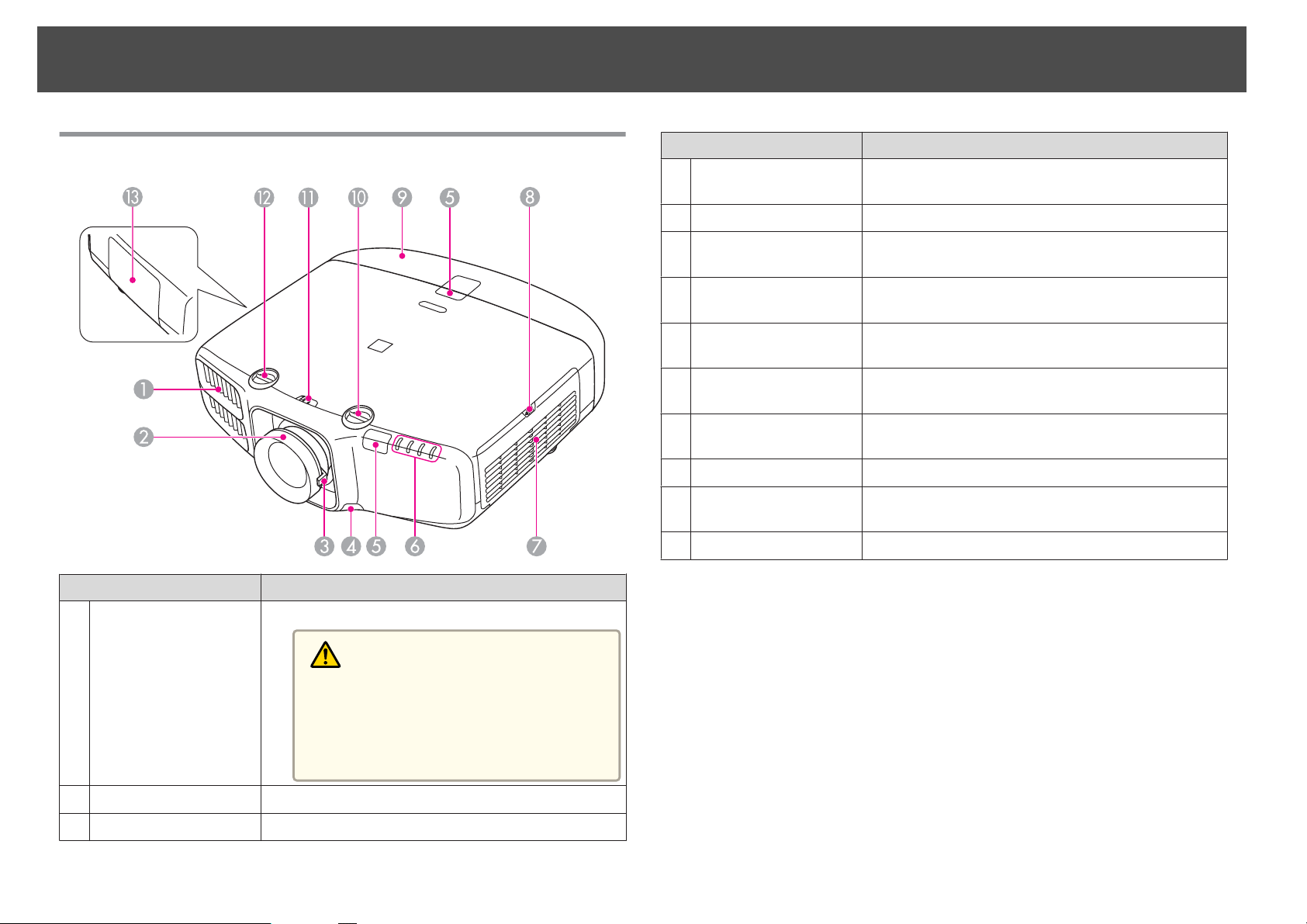
Front/Top
Name Function
Air exhaust vent
A
Exhaust vent for air used to cool the projector internally.
Name Function
Lens unit removal
D
button
Remote receiver
E
Status indicators
F
Air intake vent
G
(air filter)
Air filter cover
H
operation knob
Cable cover
I
Vertical lens shift dial
J
Lens shift dial lock
K
Horizontal lens shift
L
dial
Lamp cover
M
When replacing the lens unit, press this button and then
remove the lens unit.
Receives signals from the remote control.
The color of the indicators and whether they are flashing
or lit indicate the status of the projector. s p.16
Takes in air to cool the projector internally.
Use this knob to open the air filter cover.
Cover for the rear interface cable connection section.
s p.42
Turn the dial to move the position of the projected image
up or down. s p.22
Locks or releases the lens shift dials.
Turn the dial to move the position of the projected image
left or right. s p.22
Open when replacing the projector's lamp.
B
C
Focus ring
Zoom ring
Caution
While projecting, do not put your face or hands
near the air exhaust vent, and do not place objects
that may become warped or damaged by heat near
the vent. Hot air from the air exhaust vent could
cause burns, warping, or accidents to occur.
Adjusts the image focus. s p.23
Adjusts the image size. s p.23
Page 7
Part Names and Functions
7
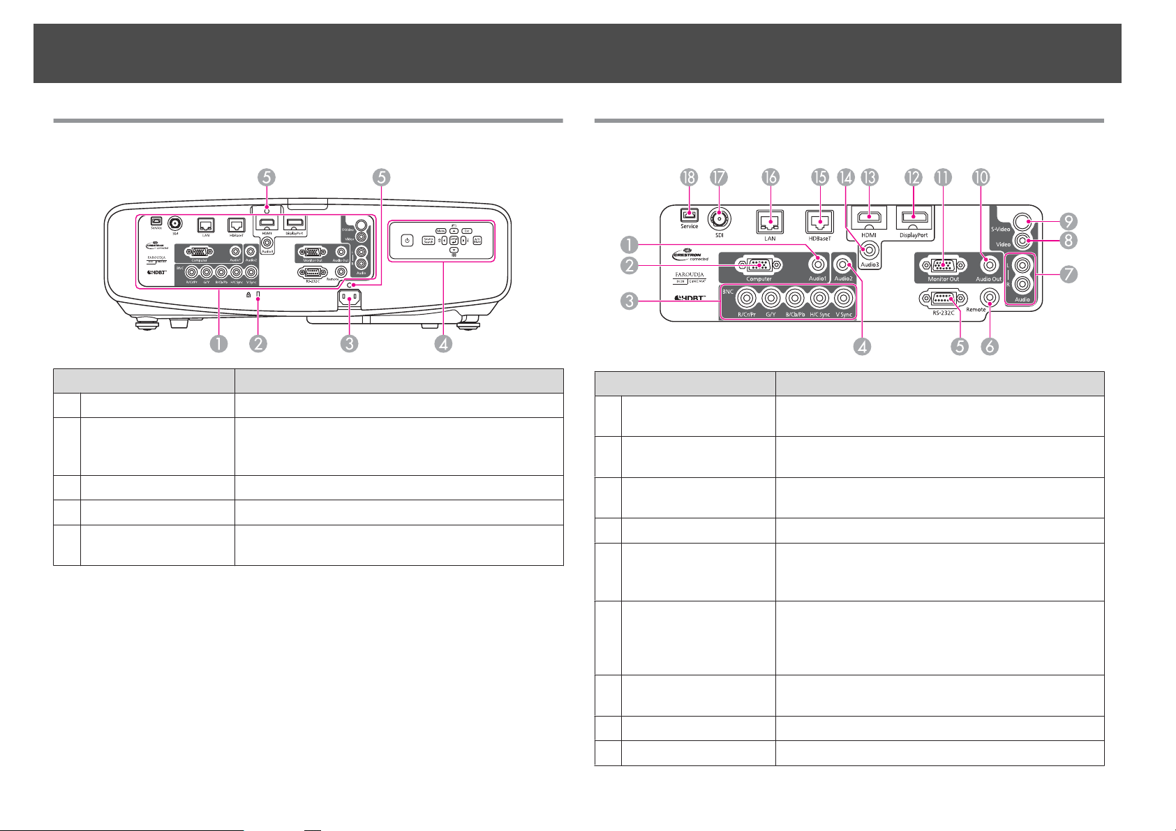
Rear
Interface
A
Security slot
B
Power inlet
C
Control panel
D
Cable holder
E
Name Function
s "Interface" p.7
The security slot is compatible with the Microsaver
Security System manufactured by Kensington.
s p.76
Connects to the power cable.
s "Control Panel" p.9
Insert the supplied cable clamp here to prevent the cable
from falling out.
Interface
Name Function
Audio1 port
A
Computer port
B
BNC port
C
Audio2 port
D
RS-232C port
E
Inputs audio from equipment connected to the Computer
port.
For analog RGB signals from a computer and component
video signals from other video sources.
For analog RGB signals from a computer and component
video signals from other video sources.
Inputs audio from equipment connected to the BNC port.
When controlling the projector from a computer, connect
it to the computer with an RS-232C cable. This port is for
control use and should not normally be used.
Remote port
F
Audio-L/R port
G
Video port
H
S-Video port
I
Connects the optional remote control cable set and inputs
signals from the remote control. When the remote control
cable is plugged into the Remote port, the remote receiver
on the projector is disabled.
Inputs audio from equipment connected to the Video port
or the S-Video port.
Inputs composite video signals from video sources.
For S-video signals from video sources.
Page 8
Part Names and Functions
8
Name Function
Audio Out port
J
Monitor Out port
K
DisplayPort
L
HDMI port
M
Audio3 port
N
HDBaseT port
O
LAN port
P
SDI port
Q
(EB-G6900WU only)
Service port
R
Outputs audio from the currently projected image to an
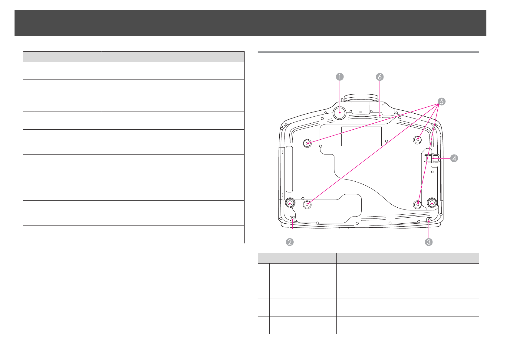
Base
external speaker.
Outputs to an external monitor the analog signal from the
computer connected to the Computer port or the BNC
port. You cannot output signals input from other ports or
component video signals.
Inputs video signals from DisplayPort compatible
computers. This projector is compatible with HDCP.
Inputs video signals from HDMI compatible video
equipment and computers. This projector is compatible
with HDCP.
Inputs audio from equipment connected to the
DisplayPort or the HDMI port.
Connects a LAN cable to the optional HDBaseT
Transmitter. s p.41
Connects a LAN cable to connect to a network.
Inputs SDI signals from a video equipment. This projector
supports SD-SDI (Standard Definition) and HD-SDI
(High Definition).
Control port used when updating the projector's software.
This should not normally be used.
Name Function
Front adjustable foot
A
Rear feet
B
Screw holes to fix the
C
cable cover
Security cable
D
installation point
When setup on a surface such as a desk, extend the foot to
adjust the position of the image. s p.24
When setup on a surface such as a desk, turn to extend and
retract to adjust the horizontal tilt. s p.25
Screw holes to fix the cable cover in place. s p.42
Pass a commercially available wire lock through here and
lock it in place. s p.77
Page 9
Part Names and Functions
9
Name Function
Ceiling mount fixing
E
points (four points)
Screw hole for the
F
screw to fix the lens
unit removal button
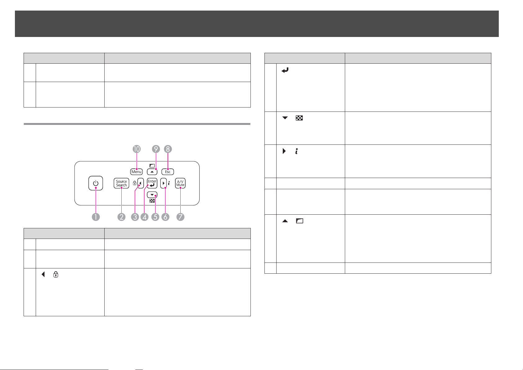
Control Panel
Name Function
[t] button
A
[Source Search]
B
button
C
[ ]/[ ] buttons
Attach the optional Ceiling Mount here when suspending
the projector from a ceiling. s p.20
When installing a lens unit, use this screw hole to fix the
lens unit removal button using the screw supplied.
p.12
s
Turns the projector power on or off.
Changes to the next input source that is sending an image.
• Displays the Control Panel Lock screen allowing you to
make settings to lock the control panel buttons.
p.75
s
• If pressed when the Configuration menu or the Help
screen is displayed, this button selects menu items and
setting values.
Name Function
D
[ ] button
E
[ ]/[ ] buttons
F
[ ] /[ ] buttons
[A/V Mute] button
G
[Esc] button
H
I
[ ]/[ ] buttons
[Menu] button
J
• When the Configuration menu or the Help screen is
displayed, it accepts and enters the current selection and
moves to the next level.
• If pressed while projecting analog RGB signals from the
Computer port or the BNC port, you can automatically
optimize Tracking, Sync., and Position.
• Displays a test pattern. s p.26
• If pressed when the Configuration menu or the Help
screen is displayed, this button selects menu items and
setting values.
• Displays the Info menu from the Configuration menu.
• If pressed when the Configuration menu or the Help
screen is displayed, this button selects menu items and
setting values.
Turns the video and audio on or off.
• Stops the current function.
• If pressed when the Configuration menu is displayed, it
moves to the previous menu level.
• Performs screen adjustments using the settings in
Geometric Correction from the Configuration menu.
s p.43
• If pressed when the Configuration menu or the Help
screen is displayed, this button selects menu items and
setting values.
Displays and closes the Configuration menu.
Page 10
Part Names and Functions
10
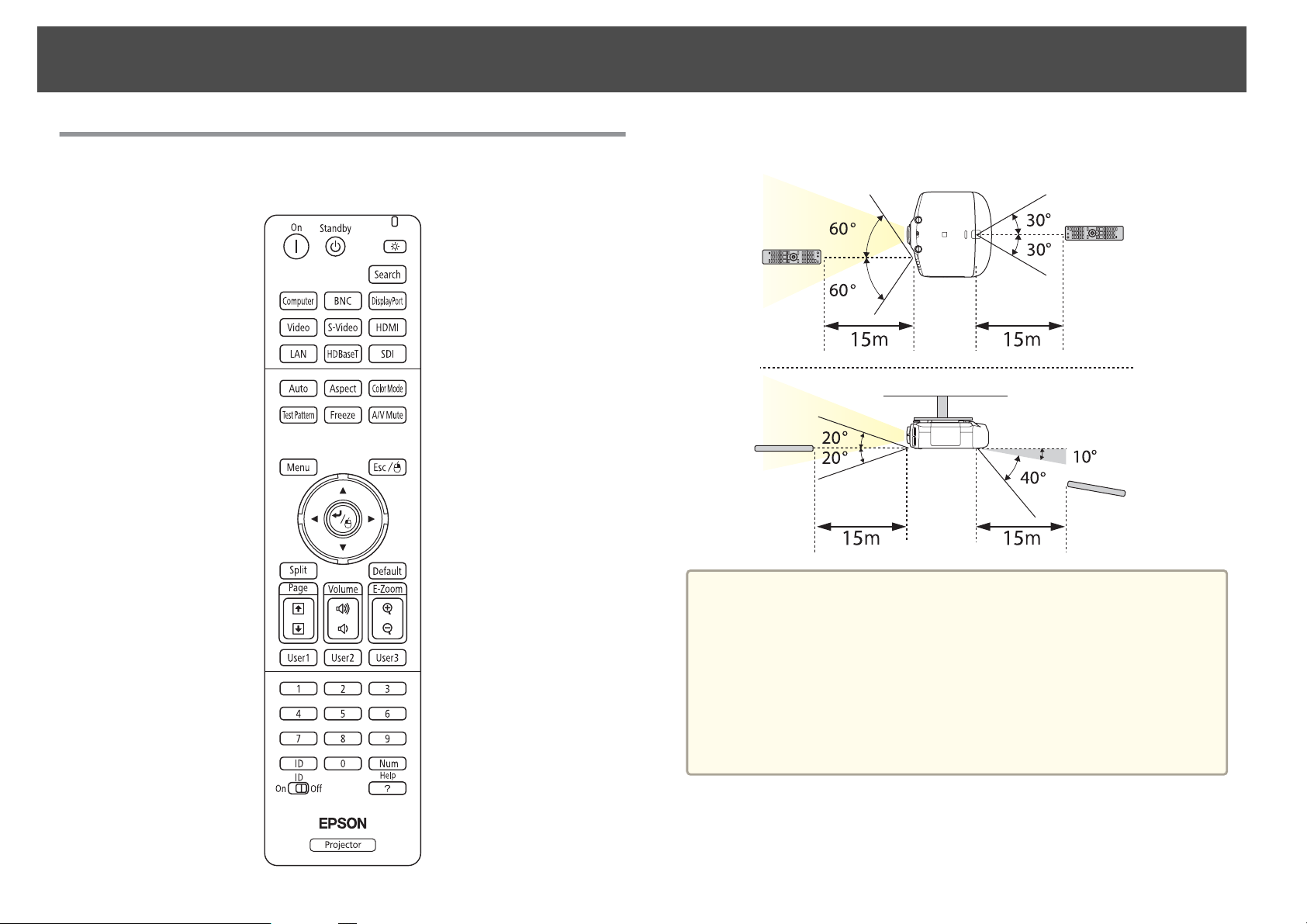
Remote Control
See the User's Guide for information on basic remote control operations.
Remote control operating range
• To restrict reception of the operation signals from the remote
a
control, set Remote Receiver.
Press [Menu] button > Settings > Remote Receiver
• When using a remote control provided with other Epson projectors,
set the Remote Control Type.
Press [Menu] button > Extended > Operation > Remote Control
Type
The operating range and operation section depends on the remote
control that you use.
Page 11
Part Names and Functions
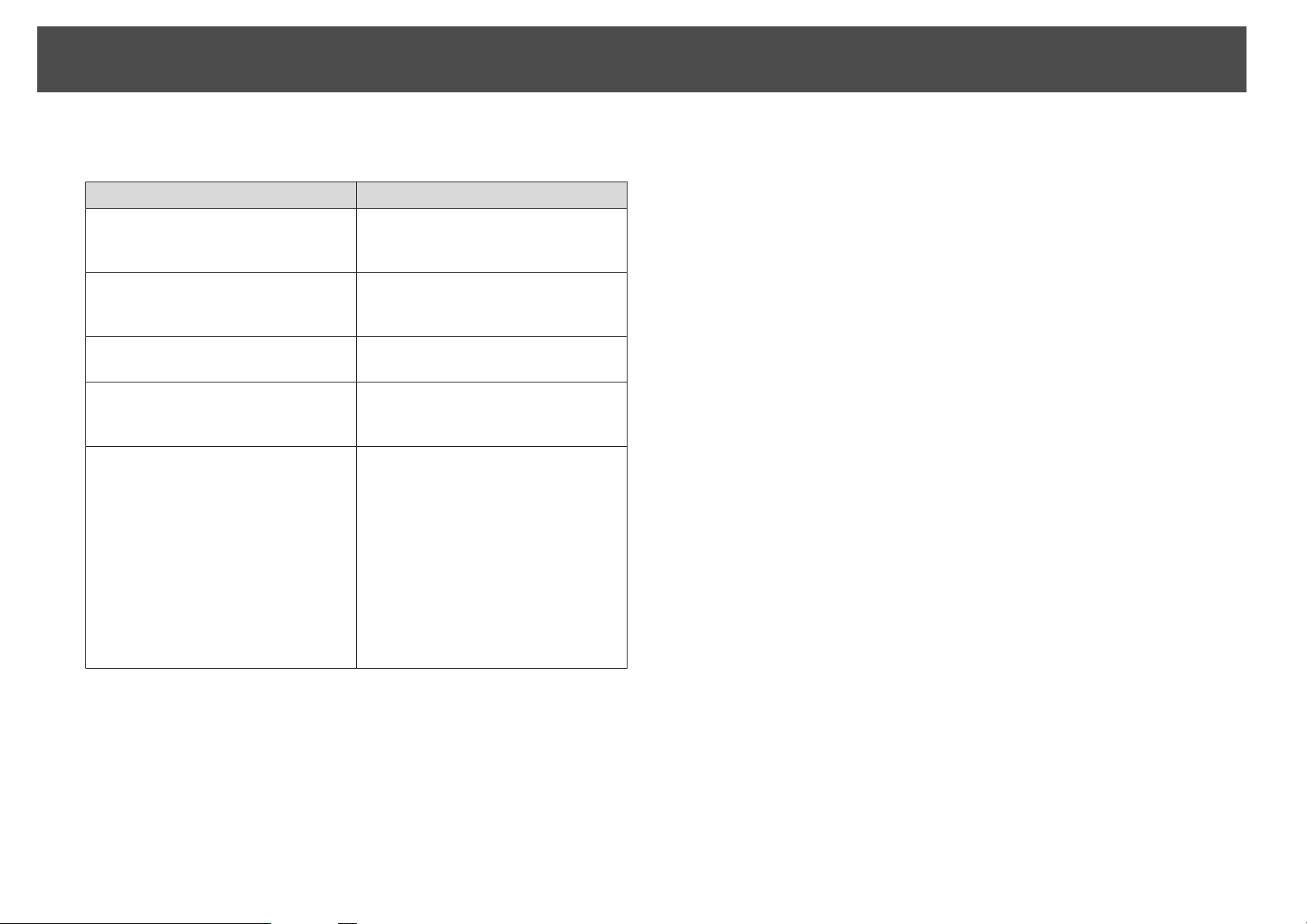
You can perform the following operations by simply pressing one button on
the remote control.
Operation Settings
Reverses the top and bottom of a projected
image. (Changes Front and Front/Ceiling
in Projection) s p.21
Sets password protection s p.73 Hold down the [Freeze] button for at least
Hold down the [A/V Mute] button for at
least five seconds.
five seconds. Make the settings on the
Password Protection screen.
11
Applies or releases a partial lock for the
remote control buttons. s p.76
Resets the Remote Receiver settings on
the Configuration menu. (Enables all of
the projector's remote receivers.)
Displays frequently used Configuration
menu items instantly.
Hold down the [Help] button for at least
five seconds.
Hold down the [Menu] button for at least
15 seconds.
Press the [User1], [User2], or [User3]
button. You can set the menu item
assigned to each button from User
Button.
Press [Menu] button > Settings > User
Button
The following items can be assigned.
Power Consumption, Info, Progressive,
Geometric Correction, MultiProjection, Resolution, Memory, or
Image Processing
Page 12
Removing and Attaching the Projector Lens Unit
12
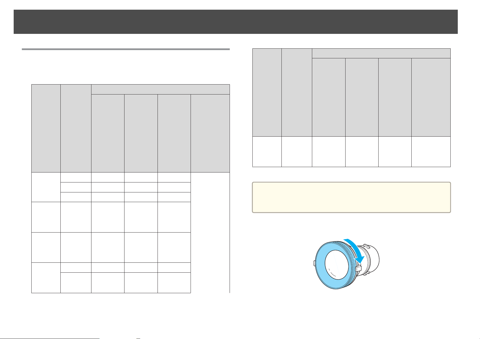
Attaching
See the following for a list of lenses that can be used with the projector.
Only use the specified lens.
Lens
Type
Standard
Lens
Short
throw
zoom
lens
Rear
projection
wide
lens
Lens
Model
Number
ELPLS06 Yes Yes Yes Not supported
ELPLS05 No Yes Yes
ELPLS03 No Yes
ELPLU01 Yes No No
ELPLR03 Yes Yes Yes
EB-
G6900WU
G6800
G6750WU
G6650WU
G6550WU
G6450WU
G6350
G6250W
G6150
G6050W
Projector Model Number
*
EB-G5350
G5300
G5200W
G5150
G5100
Yes
EB-G5950
G5900
G5800
G5750WU
G5650W
G5600
G5500
G5450WU
EB-4955WU
4950WU
4855WU
4850WU
4750W
4650
4550
Lens
Type
Long
throw
zoom
lens
This is not available for EB-G5750WU/EB-G5450WU.
*
Lens
Model
Number
ELPLL06 Yes Yes Yes
EB-
G6900WU
G6800
G6750WU
G6650WU
G6550WU
G6450WU
G6350
G6250W
G6150
G6050W
Projector Model Number
EB-G5950
G5900
G5800
G5750WU
G5650W
G5600
G5500
G5450WU
EB-G5350
G5300
G5200W
G5150
G5100
EB-4955WU
4950WU
4855WU
4850WU
4750W
4650
4550
Attention
Do not attach the lens unit when the projector's lens insertion section is
facing up. Dust or dirt could enter the projector.
Turn the focus ring clockwise until it cannot go any further.
a
Middle
throw
zoom
lens
ELPLM04 Yes Yes Yes
ELPLM05 Yes Yes Yes
Page 13
Removing and Attaching the Projector Lens Unit
13
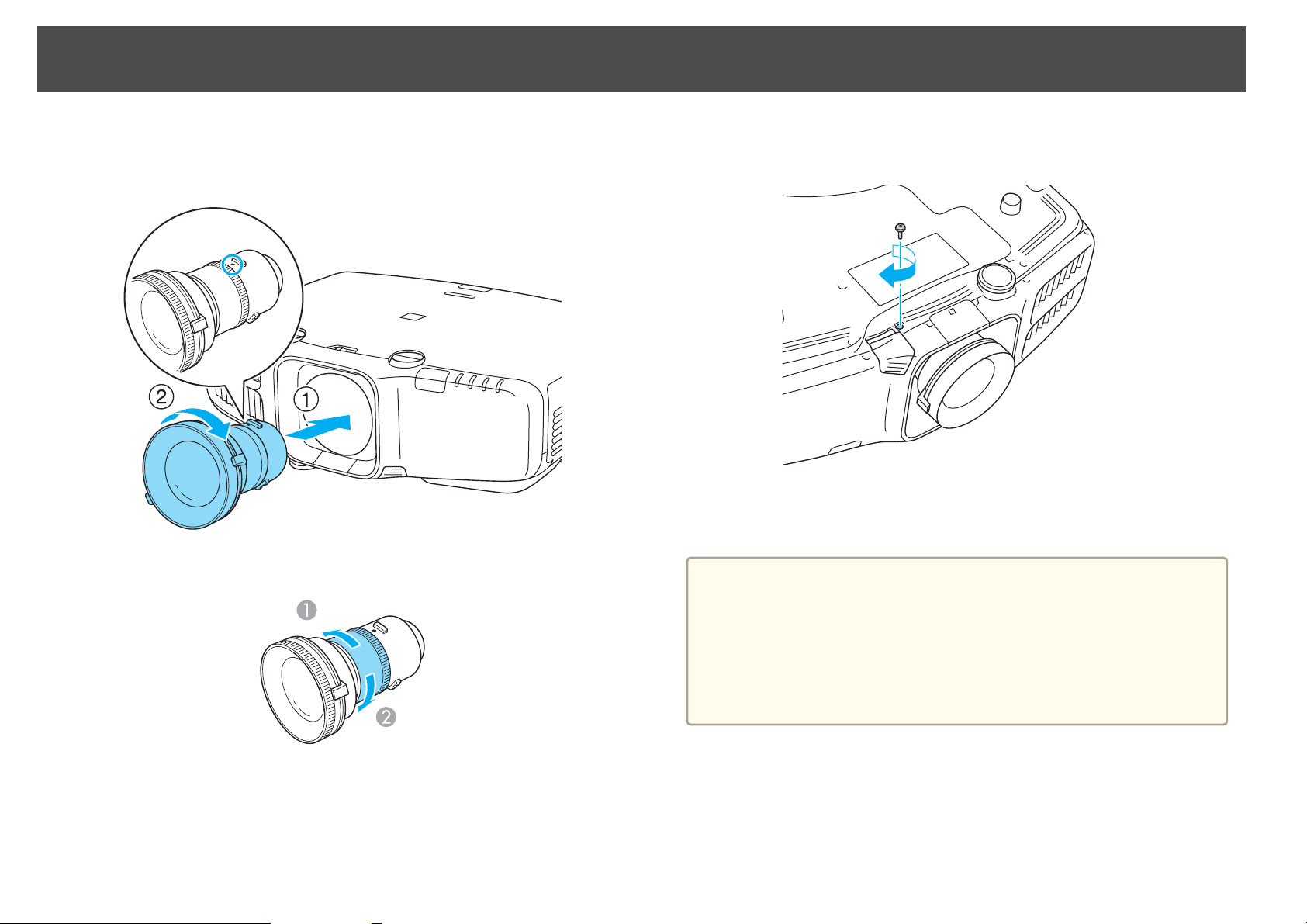
b
Insert the lens unit straight into the projector's lens socket with
the white dot at the top, and then turn it clockwise until you hear
it click into place.
Turn the torque ring on the lens unit to adjust the torque for the
zoom ring.
d
Fix the lens unit removal button with the screw supplied with the
lens unit.
Make sure you fix the lens unit removal button with the screw to
prevent the lens unit from being stolen.
Attention
• Store the projector with the lens unit installed.
If the projector is stored without the lens unit, dust and dirt may get inside
the projector and cause malfunctions or lower the quality of projection.
• When the projector is facing up (35 to 150 degrees) or down (-35 to -150
degrees), tighten the lens torque ring. Note that it could malfunction if it is
over tightened.
c
Tighter
A
Looser
B
Turn the lens unit counterclockwise and make sure that it does
not come out of the socket.
Page 14
Removing and Attaching the Projector Lens Unit
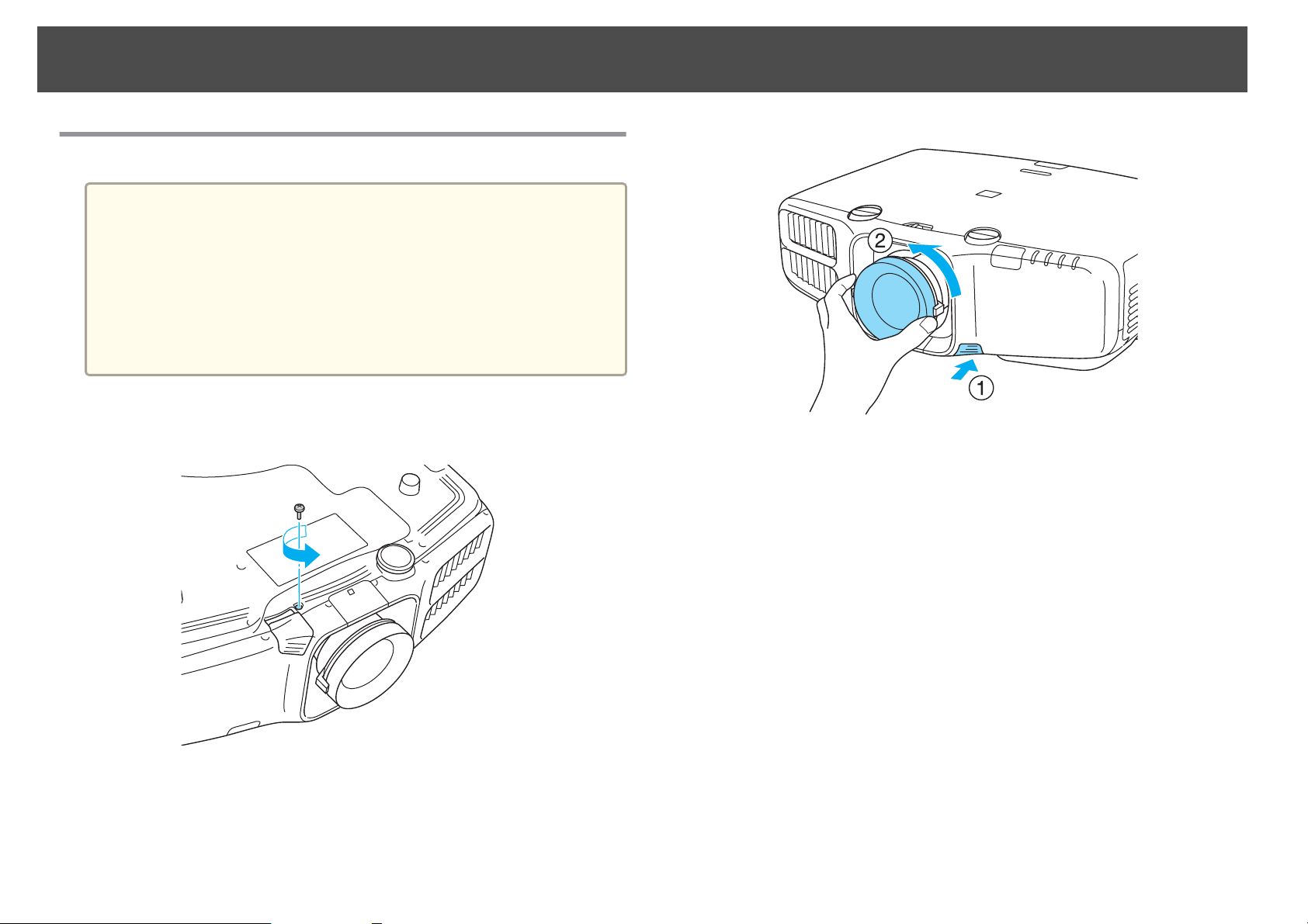
Removing
Attention
• Only remove the lens unit when necessary. If dust or dirt enter the projector,
projection quality deteriorates and it could cause a malfunction.
• Try not to touch the lens section with your hand or fingers. If fingerprints or
oils are left on the surface of the lens, projection quality deteriorates.
• If the lens shift has been done, set the lens shift to the center before replacing
the lens unit.
s "Adjusting the Position of the Projected Image (Lens Shift)" p.22
14
a
b
When the lens unit removal button is fixed with a screw, remove
the screw.
Pull the lens unit straight out as it is released.
c
While pressing the lens unit removal button, turn the lens unit
counterclockwise until you hear it click.
Page 15
Turning On and Off
15
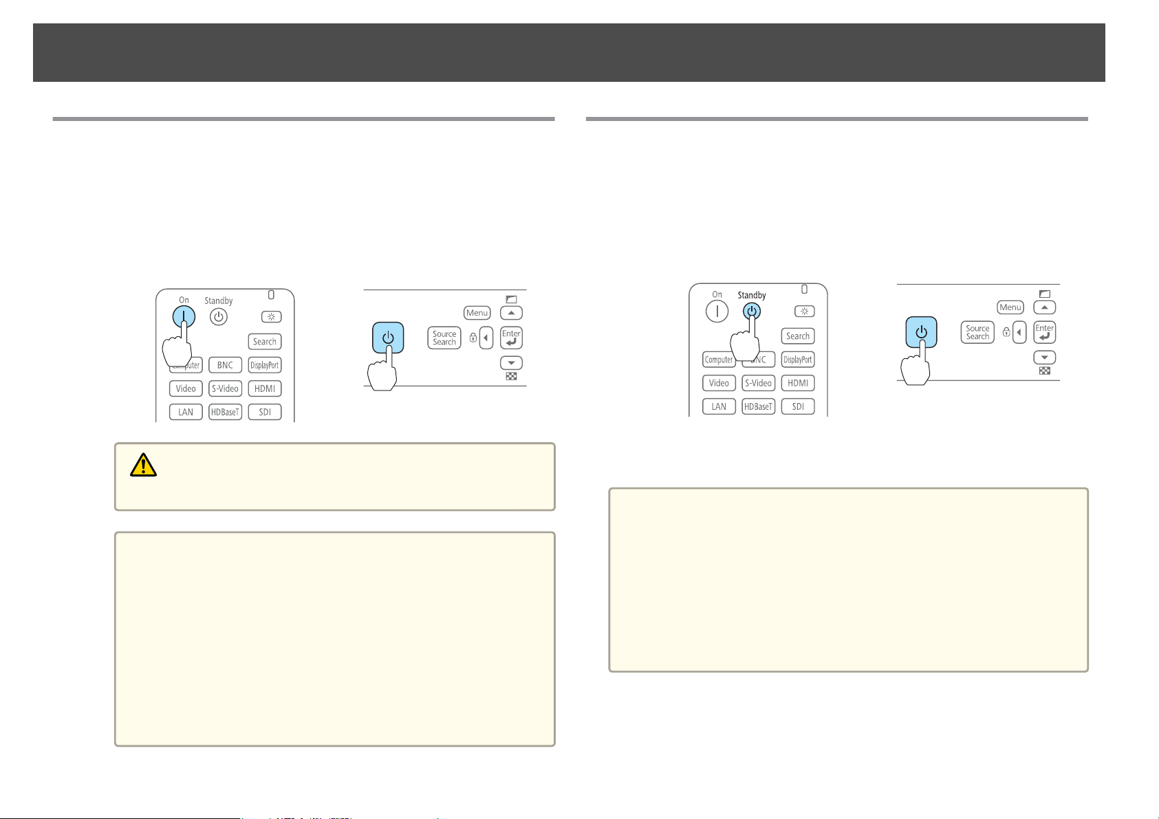
Turning On
a
Connect the power cable.
Connect the power cable supplied.
Turning on the projector.
b
Using the remote control Using the control panel
Do not look into the lens during projection.
a
Warning
• We recommend setting the focus, zoom, and lens shift at least
30 minutes after you start the projection, because images are
not stable right after turning on the projector.
• When using at an altitude of 1500 m or more, make sure you
set High Altitude Mode to On.
Press [Menu] button > Extended > Operation > High
Altitude Mode
• When you turn on the projector for the first time, the
message "Do you want to set the time?" is displayed. See the
following for more information on setting the time.
s p.29
Turning Off
a
Turn off any connected devices.
b
Press [t] once on the remote control, or press [t] twice on the
control panel.
Using the remote control Using the control panel
When the projector beeps twice, disconnect the power cable.
c
To prevent accidental operations, set Standby Confirmation to On to
a
display a confirmation message asking if you want to turn off the
projector when the [t] button is pressed on the remote control.
(When Remote Control Type is set to Simple, you cannot make
Standby Confirmation settings.)
Press [Menu] button > Extended > Display > Standby Confirmation
After making the settings, a confirmation message is displayed when
you press the [t] button on the remote control, and the projector
turns off if you press the [t] button one more time.
× 2
Page 16
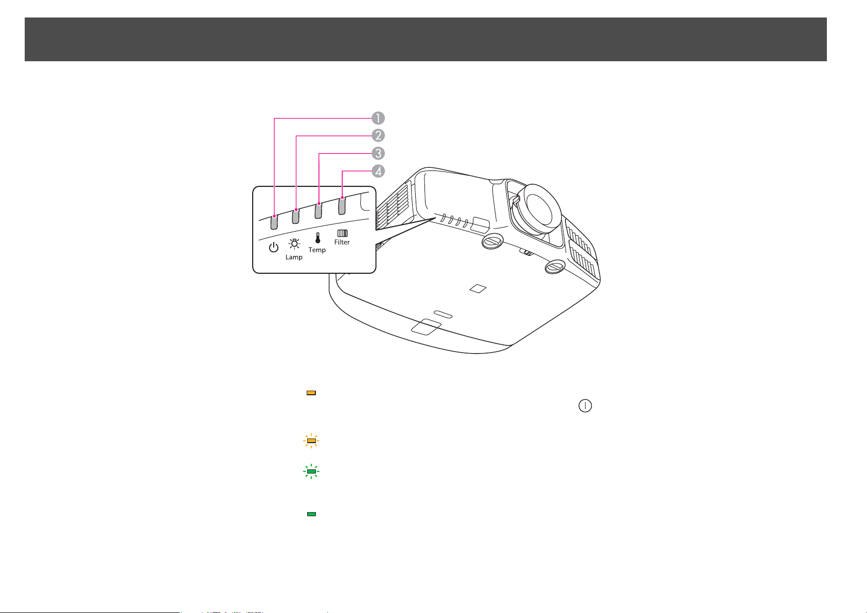
Reading the Indicators
The projector is provided with the following four indicators that indicate the operating status of the projector.
16
Power indicator Indicates the operating status.
A
Standby condition
In this status, you can start projecting by pressing the [
on the control panel.
Preparing for network monitoring or cool down in progress
All buttons are disabled while the indicator is flashing.
Warming up
Warm-up time is about 30 seconds. After warm-up is complete, the indicator stops flashing.
The [t] button is disabled during warm-up.
Projecting
Lamp indicator Indicates the projection lamp status.
B
Temp indicator Indicates the internal temperature status.
C
Filter indicator Indicates the air filter status.
D
] button on the remote control, or the [t] button
Page 17
Reading the Indicators
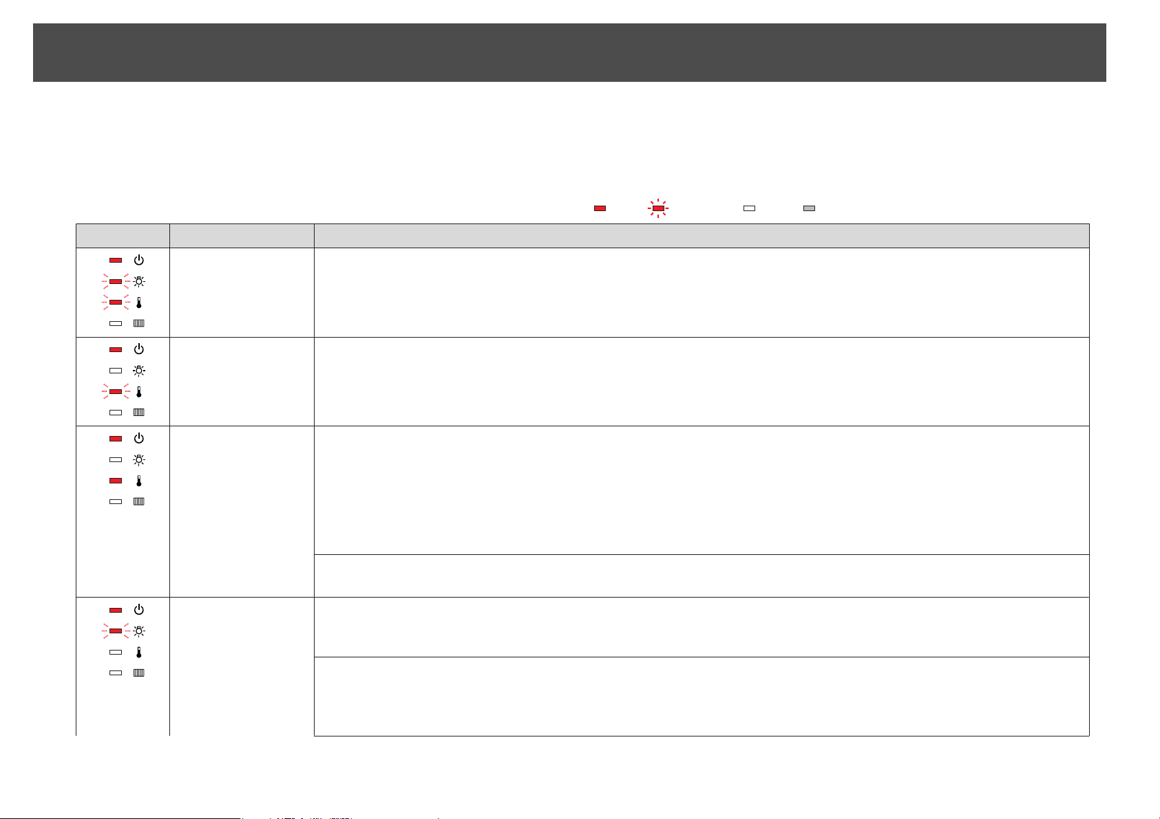
Refer to the following table to see what the indicators mean and how to remedy problems that they indicate.
If all indicators are off, check that the power cord is connected correctly and that the power is being supplied normally.
17
Sometimes, when the power cord is unplugged, the [
t
] indicator remains lit for a short period, but this is not a fault.
: Lit : Flashing : Off : Varies according to the projector status
Status Cause Remedy or Status
Internal Error Stop using the projector, remove the power plug from the electrical outlet, and contact your local dealer or the nearest address provided in the
Epson Projector Contact List.
s "Epson Projector Contact List" p.84
Fan Error
Sensor Error
High Temp Error
(Overheating)
Stop using the projector, remove the power plug from the electrical outlet, and contact your local dealer or the nearest address provided in the
Epson Projector Contact List.
s "Epson Projector Contact List" p.84
The lamp turns off automatically and projection stops. Wait for about five minutes. After about five minutes the projector switches to standby
mode, so check the following two points.
• Check that the air filter and air exhaust vent are clear, and that the projector is not positioned against a wall.
• If the air filter is clogged, remove the power plug from the electrical outlet, and clean or replace it.
If the error continues after checking the points above, stop using the projector, remove the power plug from the electrical outlet, and contact
your local dealer or the nearest address provided in the Epson Projector Contact List.
s "Epson Projector Contact List" p.84
When using at an altitude of 1500 m or more, set High Altitude Mode to On.
Press [Menu] button > Extended > Operation > High Altitude Mode
Lamp Error
Lamp Failure
Check the following two points after turning off the projector and removing the power plug from the electrical outlet.
• Take out the lamp and check if it is cracked.
• Clean the air filter.
If the lamp is not cracked: Reinstall the lamp and connect the plug to an electrical outlet.
If the error continues: Stop using the projector, remove the power plug from the electrical outlet, and contact your local dealer or the nearest
address provided in the Epson Projector Contact List.
s "Epson Projector Contact List" p.84
Page 18
Reading the Indicators
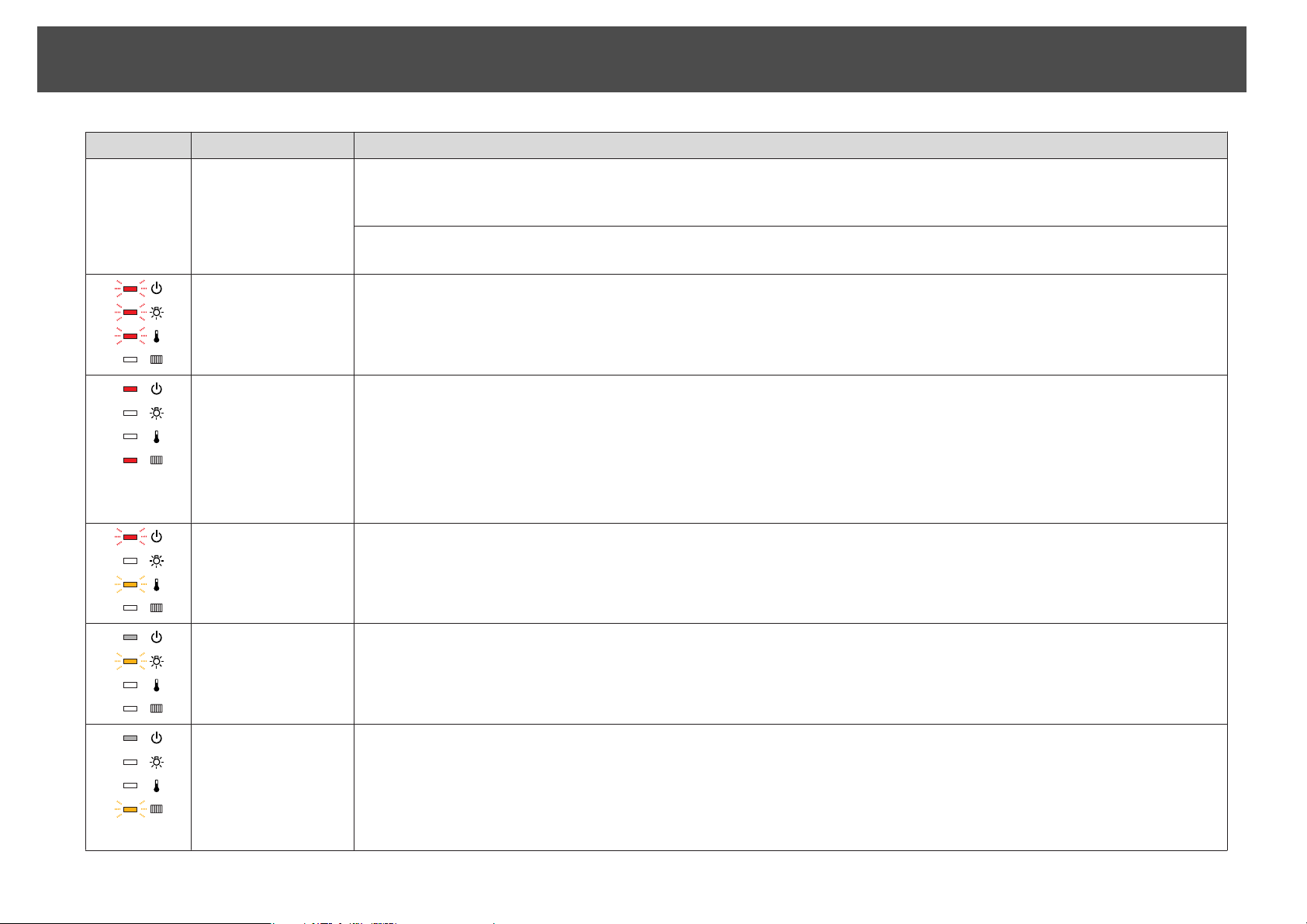
Status Cause Remedy or Status
18
If the lamp is cracked: Contact your local dealer or the nearest address provided in the Epson Projector Contact List. (Images cannot be
projected until the lamp is replaced.)
s "Epson Projector Contact List" p.84
When using at an altitude of 1500 m or more, set High Altitude Mode to On.
Press [Menu] button > Extended > Operation > High Altitude Mode
Auto Iris Error
Power Err. (Ballast)
Filter Airflow Error Check the following two points.
High Temp Warning This is not an abnormality. However, if the temperature rises too high again, projection stops automatically. Check the following two points.
Replace Lamp Replace with a new lamp after turning off the projector and removing the power plug from the electrical outlet.
Low Air Flow Check the following two points.
Stop using the projector, remove the power plug from the electrical outlet, and contact your local dealer or the nearest address provided in the
Epson Projector Contact List.
s "Epson Projector Contact List" p.84
• Check that the air filter and air exhaust vent are clear, and that the projector is not positioned against a wall.
• If the air filter is clogged, remove the power plug from the electrical outlet, and clean or replace it.
After checking, connect the power plug to an electrical outlet.
If the error continues after checking the points above, stop using the projector, remove the power plug from the electrical outlet, and contact
your local dealer or the nearest address provided in the Epson Projector Contact List.
"Epson Projector Contact List" p.84
s
• Check that the air filter and air exhaust vent are clear, and that the projector is not positioned against a wall.
• If the air filter is clogged, remove the power plug from the electrical outlet, and clean or replace it.
If you continue to use the lamp after the replacement period has passed, the possibility that the lamp may explode increases. Replace it with a
new lamp as soon as possible.
• Check that the air filter and air exhaust vent are clear, and that the projector is not positioned against a wall.
• If the air filter is clogged, remove the power plug from the electrical outlet, and clean or replace it.
If the error continues after checking the points above, stop using the projector, remove the power plug from the electrical outlet, and contact
your local dealer or the nearest address provided in the Epson Projector Contact List.
s "Epson Projector Contact List" p.84
Page 19
Reading the Indicators
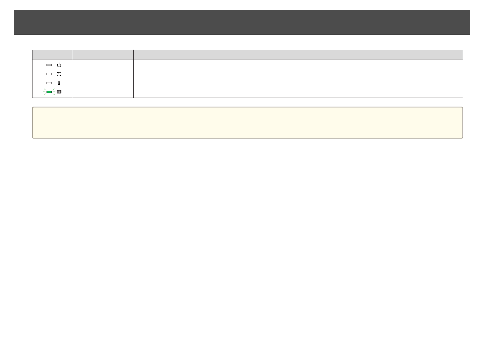
Status Cause Remedy or Status
Air Filter Notice "Time to clean the air filter. Clean or replace the air filter."is displayed. Clean the air filter after turning off the projector and removing the power
If the indicators are in a state not shown in this table, stop using the projector, remove the power plug from the electrical outlet, and contact your local dealer or
a
the nearest address provided in the Epson Projector Contact List.
s "Epson Projector Contact List" p.84
19
plug from the electrical outlet.
The indicators or messages regarding Air Filter Notice are displayed only when Air Filter Notice is set to On from the Configuration menu.
Press [Menu] button > Extended > Display > Air Filter Notice
Page 20
Installing the Projector
20
Installation Requirements
Warning
• A special method of installation is required when suspending the projector
from a ceiling (ceiling mount). If installation work is not carried out
correctly, the projector could fall down. This may result in injury or
accidents.
Contact your dealer or the nearest address provided in the Epson Projector
Contact List if you want to use this installation method.
s "Epson Projector Contact List" p.84
• If you use adhesives on the Ceiling mount fixing points to prevent the screws
from loosening, or if you use things such as lubricants or oils on the
projector, the projector case may crack causing it to fall from its ceiling
mount. This could cause serious injury to anyone under the ceiling mount
and could damage the projector.
When installing or adjusting the ceiling mount, do not use adhesives to
prevent the screws from loosening and do not use oils or lubricants and so
on.
• Do not cover the projector's air intake vent or air exhaust vent. If either of
the vents are covered, the internal temperature could rise and cause a fire.
• An optional ceiling mount is required when suspending the projector
a
from a ceiling.
• When mounted on a ceiling, set Inv Direction Button to On so that
the operations and movement of the [
buttons on the control panel match.
Press [Menu] button > Extended > Operation > Inv Direction
Button
], [ ], [ ], and [ ]
Horizontal: Can be tilted within the range of expansion and contraction for
the rear feet.
s
"Adjusting the Horizontal Tilt (When Setup on a Desk)" p.25
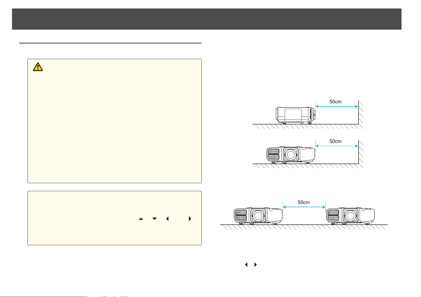
Make sure there is a gap of at least 50 cm between the wall and the air
exhaust vent and the air intake vent.
Air exhaust vent
Air intake vent
When setting up multiple projectors, make sure there is a gap of at least
50 cm between the projectors. Also, make sure the heat coming out of the
air exhaust is not taken in through the air inlet.
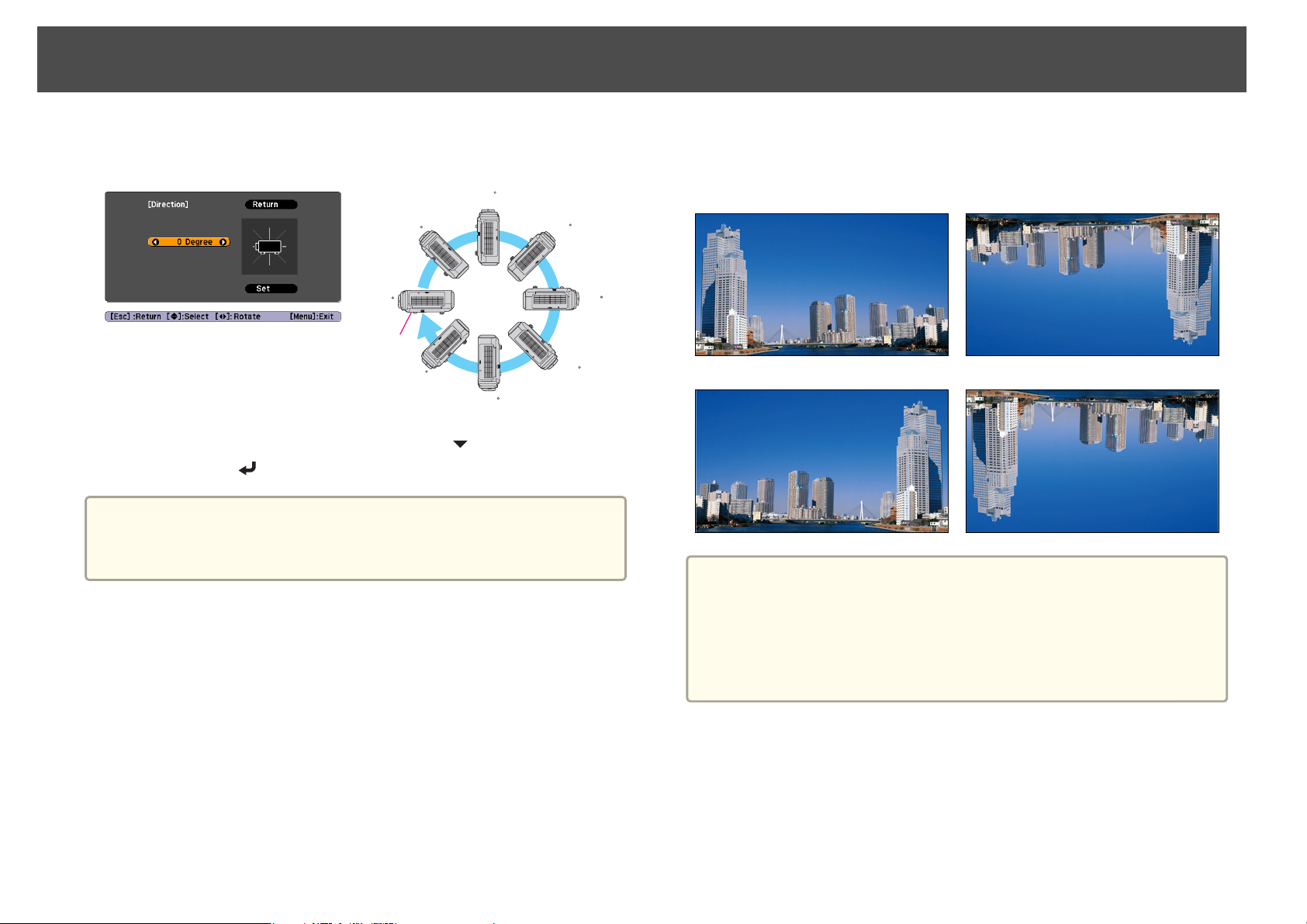
When installation is complete, set the Direction from the configuration
menu according to the vertical installation angle.
The projector can be installed at the following angles.
Vertical: Can be installed at any angle in a complete 360 degrees.
Press [Menu] button > Extended > Direction
Use the [
][ ] buttons to set the projector's installation angle.
Page 21
Installing the Projector
21
Each time you press one of the buttons, the angle of tilt changes by 15
degrees. Set as close to the actual setup angle as possible.
90
45
0
Base
-45
-90
135
-135
When you have finished making settings, use the [ ] button to select Set,
and then press the [
] button.
Attention
Make sure you set Direction correctly. The lamp's operating life may be
reduced if it is not set.
Changing the direction of the image (projection mode)
You can change the direction of the image using Projection mode from the
Configuration menu.
180
When Front is the standard, the image directions for each projection mode
are as follows.
Front (default) Front/Ceiling
Rear Rear/Ceiling
• You can change the setting as follows by pressing down the [A/V
a
Mute] button on the remote control for about five seconds.
FrontWFront/Ceiling
• Make sure you check the Direction setting when you change the
projector's installation position.
Press [Menu] button > Extended > Direction
Press [Menu] button > Extended > Projection
Page 22
Installing the Projector
22
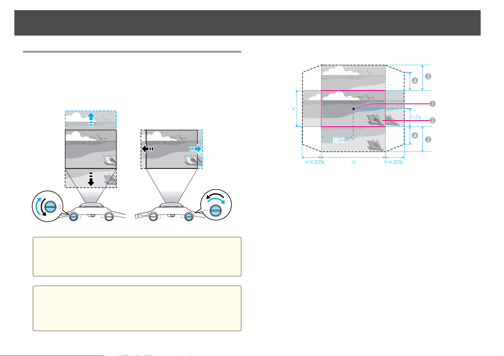
Adjusting the Position of the Projected Image (Lens Shift)
The lens can be shifted to adjust the position of the projected image, for
example, when the projector cannot be installed directly in front of the
screen.
Attention
When adjusting the image height with the vertical lens shift dial, adjust by
moving the image from the bottom to the top. If it is adjusted from the top
to the bottom, the image position may move down slightly after adjusting.
The ranges within which the image can be moved are shown below.
Center of lens
A
Projected image when lens shift is set in the center
B
Maximum range
C
EB-G6900WU: V x 67%
EB-G6800: V x 57%
When horizontal lens shift is set to the maximum
D
EB-G6900WU: V x 27%
EB-G6800: V x 19%
The position of the projected image cannot be moved to both the
horizontal and vertical maximum values.
a
• We recommend setting the focus, zoom, and lens shift at least 30
minutes after you start the projection, because images are not stable
right after turning on the projector.
• The image will be clearest when both the vertical and horizontal lens
shift are set in the center.
Page 23
Installing the Projector
23
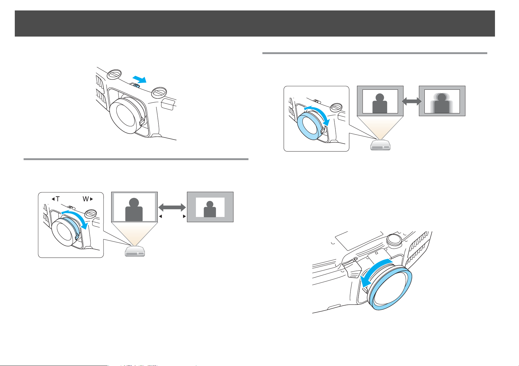
When you have finished making adjustments, lock the lens shift dial lock.
Adjusting the Zoom
Turn the zoom ring to adjust the zoom.
W T
Adjusting the Focus
Adjust the focus ring.
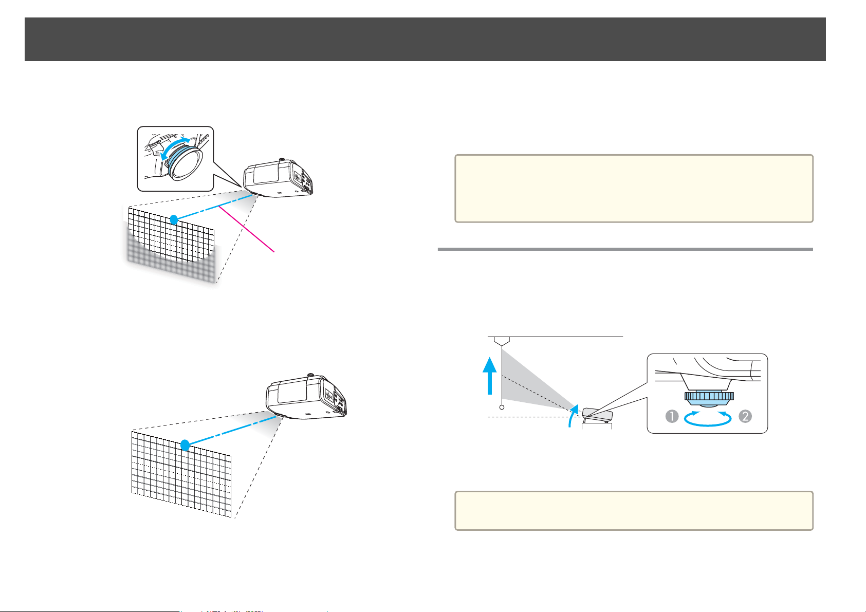
When using the short throw zoom lens ELPLU01
Follow the steps below to adjust the focus when the lens is shifted up,
down, left, or right using the lens shift function.
a
Turn the distortion ring anti-clockwise until it cannot go any
further.
Page 24
Installing the Projector
24
b
c
Focus the image around the axis of the lens using the focus ring.
Example: When the lens shift is turned all the way down.
Optical axis
Correct screen distortion using the distortion ring.
When correcting distortion, the area around the edges of the image
is also focused.
d
Turn the focus ring to focus the entire screen.
If the area around the lens axis is out of focus, fine-tune by turning
the distortion ring.
When using the short throw zoom lens ELPLU01, set Lens Type to
a
ELPLU01 from the Configuration menu so that keystone correction is
performed correctly.
Press [Menu] button > Extended > Operation > Lens Type
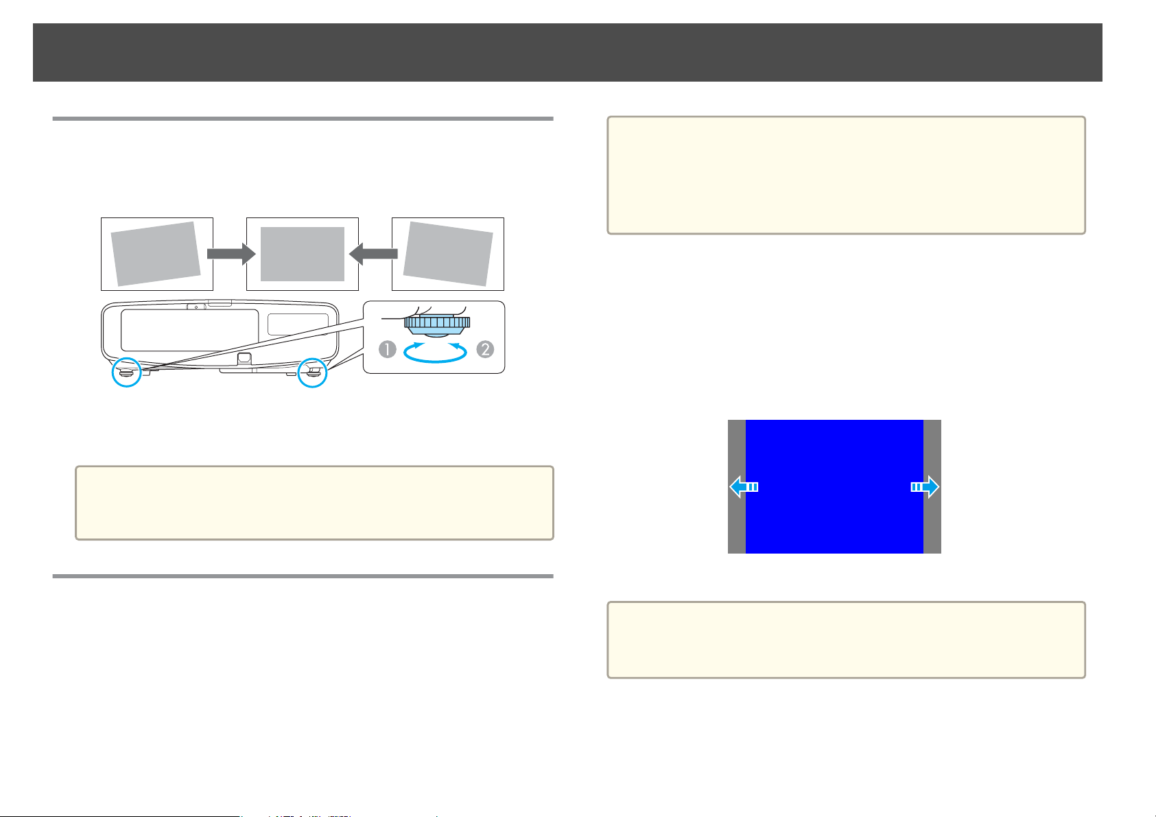
Adjusting the Image Position (When Setup on a Desk)
Extend or retract the front foot to make adjustments. You can adjust the
position of the image by tilting the projector up to 10 degrees.
Extend the front foot.
A
Retract the front foot.
B
The larger the angle of tilt, the harder it becomes to focus. Install the
a
projector so that it only needs to be tilted at a small angle.
Page 25
Installing the Projector
25
Adjusting the Horizontal Tilt (When Setup on a Desk)
Extend and retract the rear feet to adjust the projector's horizontal tilt.
Extend the rear foot.
A
Retract the rear foot.
B
Attention
The rear feet can be attached and removed. Note that the feet will detach if
they are extended more than 10 mm.
The default values are shown below.
a
Adjusting the position of the image on the projected screen
You can adjust the position of the image if there are margins between the
edge of the image and the projected screen frame due to the Screen Type
setting.
Press [Menu] button > Extended > Display > Screen > Screen Position
Example: When the Screen Type is set to 4:3 for EB-G6900WU
EB-G6900WU: 16:10
EB-G6800: 4:3
You do not need to set the Screen Type when the default value is the
same as the aspect ratio for the screen being used.
Screen Settings
Set the Screen Type to 4:3, 16:9, or 16:10 according to the aspect ratio of
the screen being used
Press [Menu] button > Extended > Display > Screen > Screen Type
The area where the image is displayed matches the shape of the screen.
You can move the image to the left and right.
The Screen Position cannot be adjusted in the following situations.
a
• If the Screen Type is set to 16:10 when using EB-G6900WU
• If the Screen Type is set to 4:3 when using EB-G6800
Page 26
Installing the Projector
26
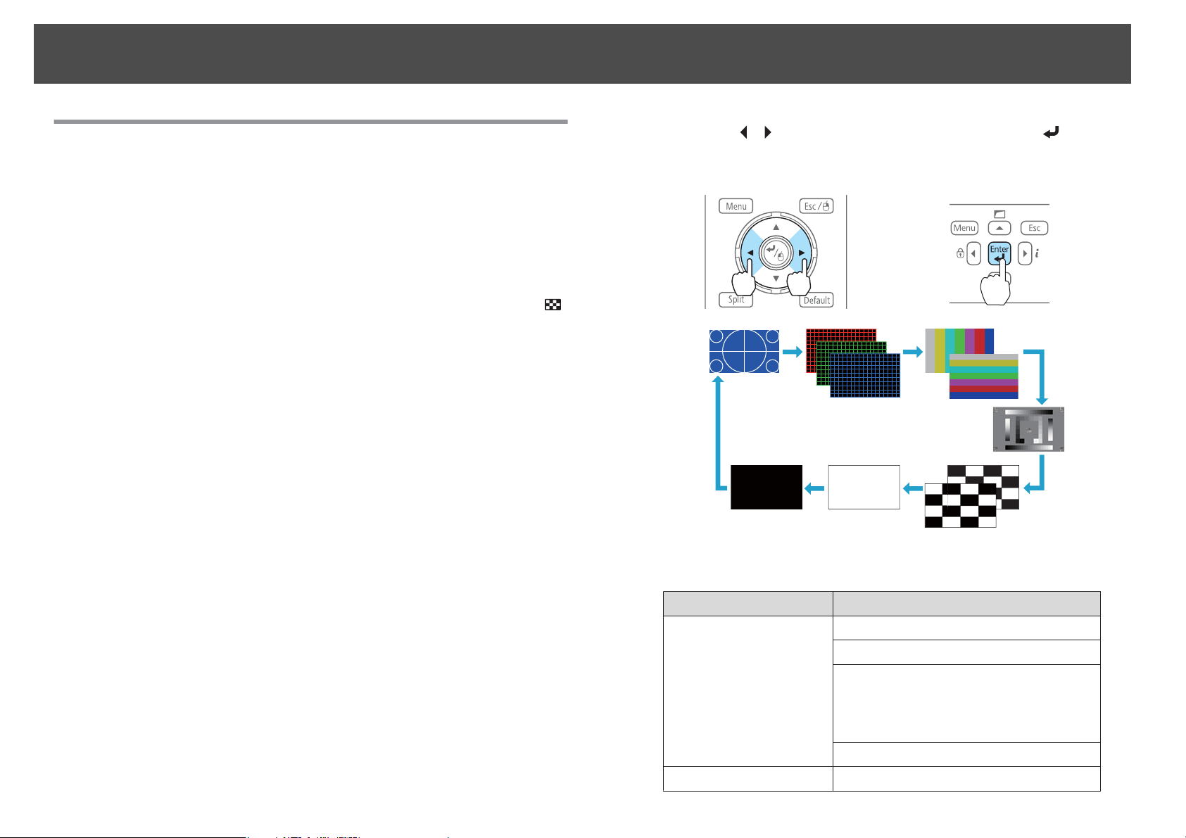
Displaying a Test Pattern
A test pattern can be displayed to adjust the projection status without
connecting video equipment.
The shape of a test pattern is according to the setting of Screen Type. Set
Screen Type first.
Press [Menu] button > Extended > Display > Screen > Screen Type
a
Press the [Test Pattern] button on the remote control or the [ ]
button on the control panel while projecting.
b
Press the [ ][ ] buttons on the remote control or the [ ] button
on the control panel to change the test pattern.
Using the remote control Using the control panel
The following image adjustments can be made while the test pattern
is being displayed.
Top Menu Name Sub Menu/Items
Image
Signal
Color Mode
Abs. Color Temp.
Advanced
- Gamma
- RGB
- RGBCMY
Reset
Auto Setup
*1
Page 27
Installing the Projector
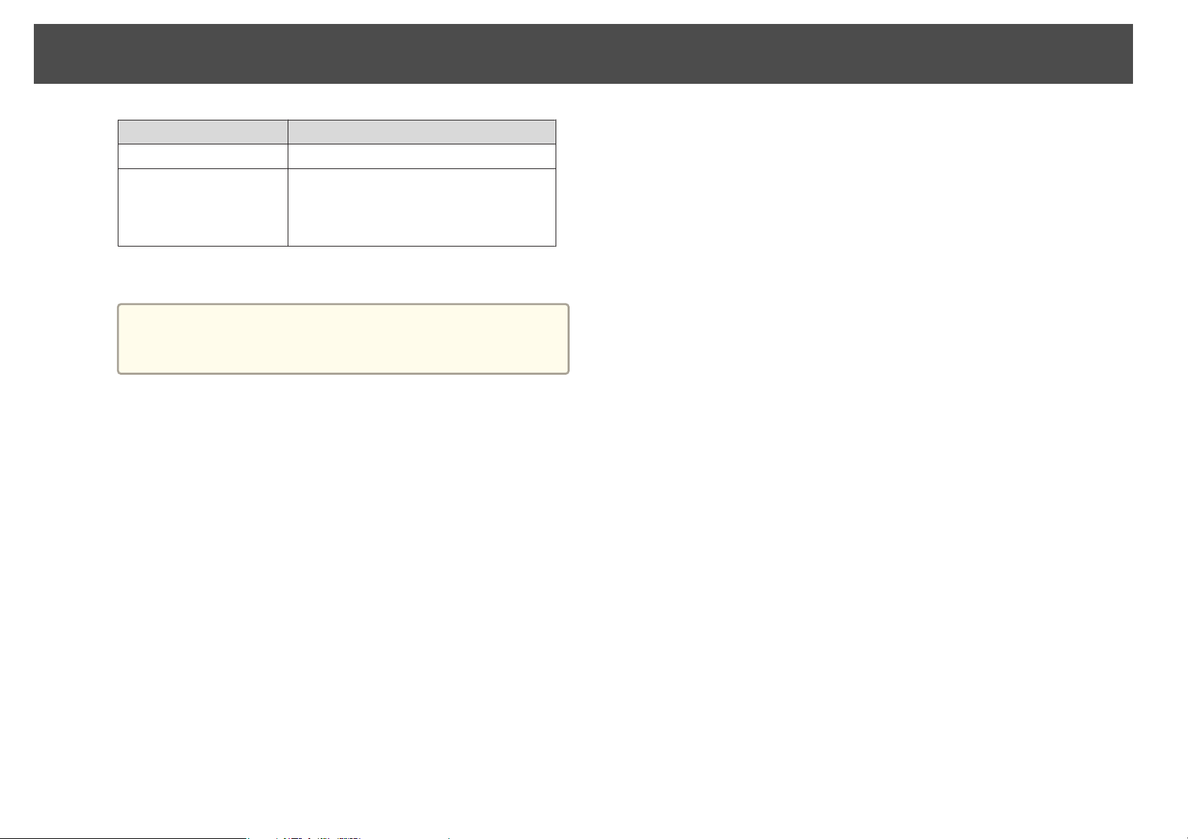
Top Menu Name Sub Menu/Items
27
Settings
Extended
Except for custom settings of gamma
*1
*2Except for Black Level
To set menu items that cannot be set while the test pattern is
a
being displayed or to fine-tune the projected image, project an
image from the connected device.
Geometric Correction s p.43
Multi-Projection s p.63
- Brightness Level
- Edge Blending
- Multi-screen
*2
Page 28
Setting Up
28
ID Settings
When an ID is set for the projector and the remote control, you can use
the remote control to operate only the projector with a matching ID. This
is very useful when managing multiple projectors.
• Operation using the remote control is possible only for projectors
a
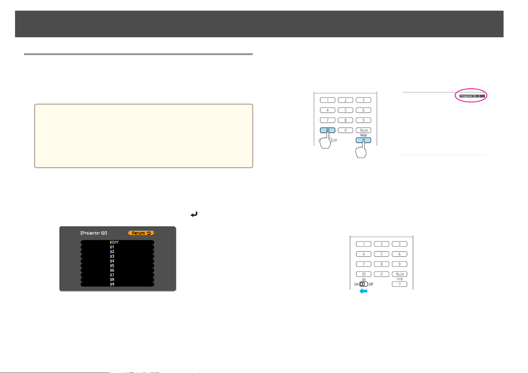
Set the projector ID
Press [Menu] button > Extended > Multi-Projection > Projector ID
Select the ID you want to set, and then press the [
that are within the operating range of the remote control.
s p.10
• When Remote Control Type is set to Simple from Operation in the
configuration menu, you cannot set the remote control ID.
• IDs are ignored when the projector ID is set to Off or the remote
control ID is set to 0.
] button.
Checking the Projector ID
During projection, press the [Help] button while holding the [ID] button.
Remote control
When you press the buttons, the current Projector ID is displayed on the
projection screen. It disappears in about three seconds.
Setting the remote control ID
Set the remote control [ID] switch to On.
a
Page 29
Setting Up
29
b
Once this setting has been made, the projector that can be operated by the
remote control is limited.
While holding the [ID] button, press a number button to select a
number to match the ID of the projector you want to operate.
s
"Checking the Projector ID" p.28
Remote control
The remote control ID setting is saved in the remote control. Even if
a
the remote control batteries are removed to replace them and so on,
the stored ID setting is retained. However, if the batteries are left out
for a long time, it is reset to the default value (ID0).
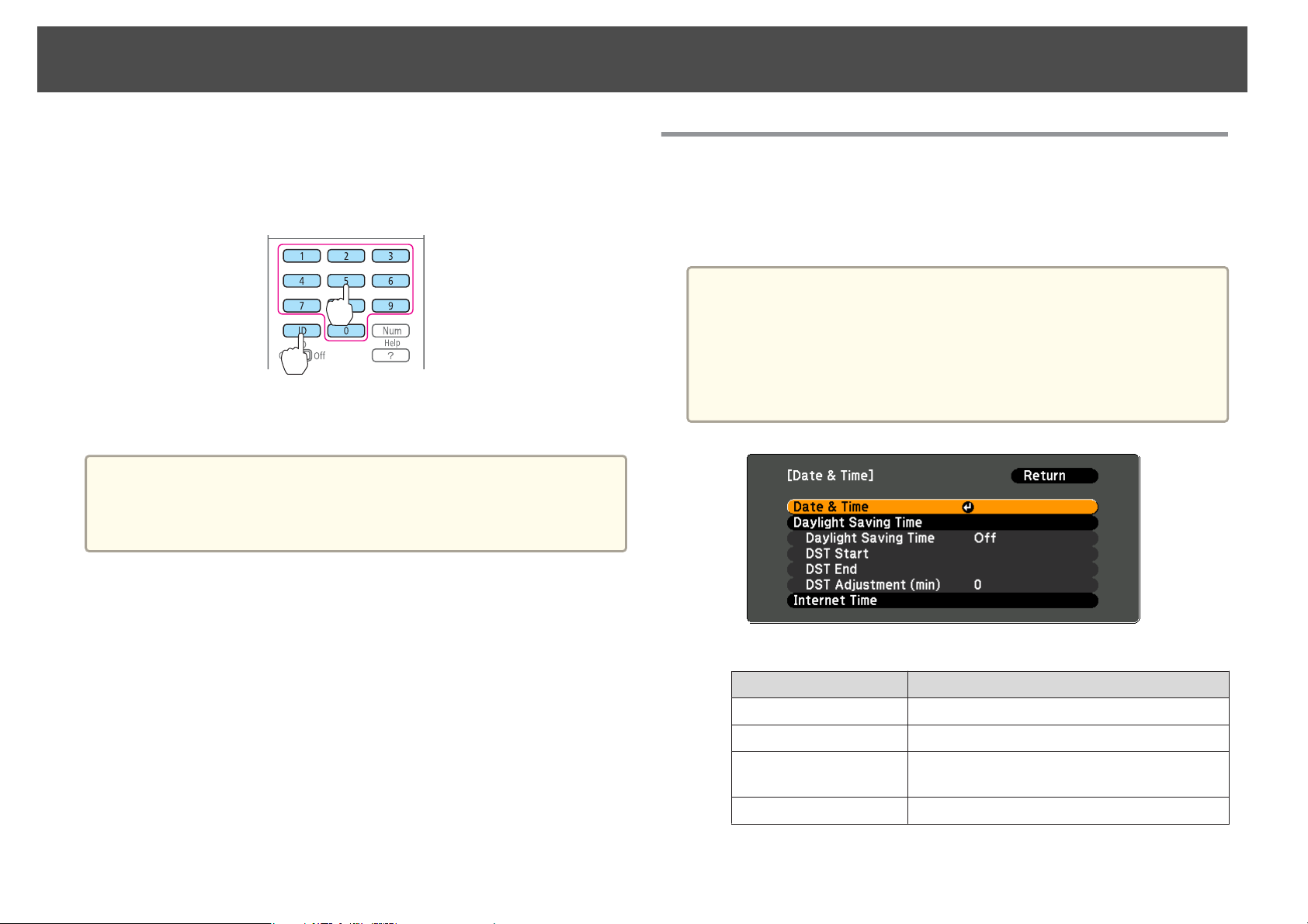
Setting the Time
You can set the time for the projector. The set time is used for the schedule
function.
Press [Menu] button > Extended > Operation > Date & Time
• When you turn on the projector for the first time, the message "Do
a
you want to set the time?" is displayed. When you select Yes, the
following screen displayed.
• When Time/Schedule Protection is set to On in Password
Protection, settings related to the date and time cannot be changed.
You can make changes after setting Time/Schedule Protection to
Off. s p.73
Date & Time
Date
Time
Time Difference (UTC)
Set
Submenu Function
Set today's date.
Set the current time.
Set the time difference from Coordinated
Universal Time.
The settings made in Date & Time are applied.
Page 30

Setting Up
Daylight Saving Time
Daylight Saving Time
30
Submenu Function
Set whether or not (On/Off) to activate the
daylight saving time.DST Adjustment (min)
adjusts the time difference between the standard
time and the daylight saving time.
DST Start
DST End
Set
Internet Time
Internet Time
Internet Time Server
Set
When changing settings, make sure you select Set, and then press the
a
[
Set the date and time to start the daylight saving
time.
Set the date and time to end the daylight saving
time.
The settings made in Daylight Saving Time are
applied.
Submenu Function
Set to On to update the time automatically through
an Internet time server.
Input the IP address for an Internet time server.
The settings made in Internet Time are applied.
] button.
Page 31

Setting Up
Other Settings
Setting basic operations
You can make settings for basic operations such as turning the projector on or off in Operation from the Configuration menu.
Press [Menu] button > Extended > Operation
You can make the following settings in Operation.
Operation Settings
Turn the projector on or off by turning the main power
supply on or off or by plugging in or unplugging the
power cable.
Set Direct Power On to On. (Default: Off)
31
Stop projection automatically when no image signal is
being input and no operations are carried out.
Use the projector above an altitude of 1500 m. Set High Altitude Mode to On. (Default: Off)
Start projecting images from the same source as last time
when the projector is turned on.
Control the projector from a computer using
communication commands without releasing A/V mute.
Turn off the confirmation buzzer that beeps when the
power turns on or off.
*1Because the default is On, the projector automatically detects image signals being input when it is turned on.
*2 The default value is Any Button. A/V mute is released when any operation is performed on the projector.
Set Sleep Mode to On. (Default: On) Set the time until the projector enters sleep mode in Sleep Mode Timer.
You can set within a range of 1 to 30 minutes. (Default: 30min.)
Set Startup Source Search to Off. (Default: On)
Set A/V Mute Release to A/V Mute. (Default: Any Button)
Set Beep to Off. (Default: On)
*1
*2
Page 32

Setting Up
Setting the display
You can make settings for menus, messages, and the background display in Display from the Configuration menu.
Press [Menu] button > Extended > Display
You can make the following settings in Display.
Operation Settings
Change the menu display position. Select the position in Menu Position.
32
Do not display messages on the projection screen such as
the source name when the source is changed, or warnings
such as when the internal temperature rises.
Change the background screen display. You can select Blue, Black, or Logo. If no logo has been registered, the Epson logo is displayed.
To prevent accidental operations, a confirmation message
is displayed asking if you want to turn off the projector
when you press the [t] button on the remote control.
*1 Displays operation and movement dialogs, lamp replacement messages, Message Broadcasting exiting messages, and the projector ID.
*2When A/V Mute Release is set to A/V Mute, Black is set.
*1
Set Messages to Off. (Default: On)
You can check warnings from the indicator status.
s "Reading the Indicators" p.16
Display Background: Set the screen background when no image signal is available. (Default: Blue)
Startup Screen: When the projector is turned on, set On to display the user's logo or Off. (Default: On)
A/V Mute: Set the screen displayed
Set Standby Confirmation to On. (Default: Off)
*2
when A/V mute is enabled. (Default: Black)
Page 33

Setting Up
Saving a User's Logo
Once a user's logo has been saved, the logo cannot be returned to the
a
factory default (the Epson logo).
33
a
b
c
d
Project the image you want to save as the user's logo.
Select User's Logo from the Configuration menu.
Press [Menu] button > Extended > User's Logo
When the message "Choose this image as the User's Logo?" is
displayed, select Yes.
Select the range of images to use as the user's logo.
Select the zoom factor.
When the message "Save this image as the User's Logo?" is displayed,
select Yes to complete registration.
Page 34

Connecting Equipment
The port name, location, and connector orientation differ depending on the source being connected.
Connecting a Computer
To project images from a computer, connect the computer using one of the following methods.
When using the supplied computer cable
A
Connect the computer's display output port to the projector's Computer port.
You can output audio from the projector's Audio Out port by connecting the audio output port on the computer to the projector's Audio1 port using a commercially available audio
cable.
When using a commercially available 5BNC cable
B
Connect the computer's display output port to the projector's BNC port.
You can output audio from the projector's Audio Out port by connecting the audio output port on the computer to the projector's Audio2 port using a commercially available audio
cable.
When using a commercially available HDMI cable
C
Connect the HDMI port on the computer to the projector's HDMI port.
The computer's audio is also output from the projector's Audio Out port.
When using a commercially available DisplayPort cable
D
Connect the computer's DisplayPort to the projector's DisplayPort.
The computer's audio is also output from the projector's Audio Out port.
34
Page 35

Connecting Equipment
35
Computer
a
4
Audio1
BNC
Audio2
HDMIOUTHDMI
4
DisplayPort DisplayPortOUT
• Change the audio output from Audio Settings.
Press [Menu] button > Extended > A/V Settings > Audio Settings
• If audio is not sent using an HDMI or DisplayPort cable, connect a commercially available audio cable to the Audio3 port to send the audio. Set HDMI Audio
Output or DisplayPort Audio Output to Audio3.
Press [Menu] button > Extended > A/V Settings > Audio Settings > HDMI Audio Output, DisplayPort Audio Output
• Some commercially available DisplayPort cables come with a lock. When removing the cable, press the button on the cable's connector section and pull out the
cable.
Page 36

Connecting Equipment
Connecting Image Sources
To project video images, connect using one of the following methods.
When using a commercially available video cable
A
Connect the video output port on the image source to the projector's Video port.
You can output audio from the projector's Audio Out port by connecting the audio output port on the image source to the projector's Audio-L/R port using a commercially available
audio cable.
When using a commercially available S-video cable
B
Connect the S-video output port on the image source to the projector's S-Video port.
You can output audio from the projector's Audio Out port by connecting the audio output port on the image source to the projector's Audio-L/R port using a commercially available
audio cable.
When using an optional component video cable (ELPKC19: D-sub/component converter)
C
Connect the component output port on the image source to the projector's Computer port.
You can output audio from the projector's Audio Out port by connecting the audio output port on the video equipment to the projector's Audio1 port using a commercially available
audio cable.
When using a commercially available component video cable (RCA) and a BNC/RCA adapter
D
Connect the component output port on the video equipment to the projector's BNC port (R/Cr/Pr, G/Y, B/Cb/Pb).
You can output audio from the projector's Audio Out port by connecting the audio output port on the video equipment to the projector's Audio2 port using a commercially available
audio cable.
When using a commercially available HDMI cable
E
Connect the HDMI port on the image source to the projector's HDMI port.
The image source's audio is also output from the projector's Audio Out port.
When using a commercially available BNC video cable (EB-G6900WU only)
F
Connect the SDI port on the image source to the projector's SDI port.
Audio output is not supported.
36
Page 37

Connecting Equipment
4
37
Video
Video
AUDIOOUT(L,R)
Audio-L/R
S-Video
56
S-Video
Audio-L/R
Computer
Audio1
AUDIOOUT(L,R)
Y
Cb/Pb
Cr/Pr
AUDIOOUT
4
BNC(R/Cr/Pr,G/Y,B/Cb/Pb)
Audio2
5
HDMI
6
SDI
Y
Cb/Pb
Cr/Pr
AUDIOOUT
HDMIOUT
SDIOUT
Page 38

Connecting Equipment
Attention
• If the input source is on when you connect it to the projector, it could cause a malfunction.
• If the orientation or shape of the plug differs, do not try to force it in. The device could be damaged or could malfunction.
• Change the audio output from Audio Settings.
a
Press [Menu] button > Extended > A/V Settings > Audio Settings
• If audio is not sent using an HDMI cable, connect a commercially available audio cable to the Audio3 port to send the audio. Set HDMI Audio Output to
Audio3.
Press [Menu] button > Extended > A/V Settings > Audio Settings > HDMI Audio Output
• If the source you want to connect to has an unusually shaped port, use the cable supplied with the device or an optional cable to connect to the projector.
• When using a commercially available 2RCA(L/R)/stereo mini-pin audio cable, make sure it is labeled "No resistance".
38
Page 39

Connecting Equipment
Connecting External Equipment
You can output images and audio by connecting an external monitor or speaker.
When outputting images to an external monitor
A
Connect the external monitor to the projector's Monitor Out port using the cable supplied with the external monitor.
When outputting audio to an external speaker
B
Connect the external speaker to the projector's Audio Out port using a commercially available audio cable.
39
MonitorOut D-Sub
a
AudioOut AudioIN
• Make the following settings to output image and audio even when the projector is in standby mode.
Set Standby Mode to Communication On.
Press [Menu] button > Extended > Standby Mode
Set A/V Output to Always On.
Press [Menu] button > Extended > A/V Settings > A/V Output
• Only analog RGB signals being input to the Computer port or the BNC port can be output to an external monitor.
Page 40

Connecting Equipment
Connecting a LAN Cable
Connect a LAN port on network hubs or other equipment to the projector's LAN port with a commercially available 100BASE-TX or 10BASE-T LAN
cable.
By connecting a computer to the projector over a network, you can project images and check the status of the projector.
LAN
To prevent malfunctions, use a category 5 or higher shielded LAN cable.
a
40
Page 41

Connecting Equipment
Connecting an HDBaseT Transmitter
Connect the optional HDBaseT Transmitter with a commercially available 100BASE-TX LAN cable.
HDBaseT
• Make sure you read the User's Guide supplied with the HDBaseT transmitter carefully before use. Make sure the HDBaseT transmitter is properly earthed before
a
use.
• Use a category 5e or category 6 shielded LAN cable.
• When connecting or disconnecting the LAN cable, make sure you turn off the power for the projector and the HDBaseT transmitter.
• When performing Ethernet communication or serial communication, or when using the wired remote control via HDBaseT port, set Control Communications
to On from the Configuration menu.
Press [Menu] button > Extended > HDBaseT > Control Communications
Note that when Control Communications is set to On, the projector's LAN port, RS-232C port, and Remote port are disabled.
41
Page 42

Connecting Equipment
Attaching the Cable Cover
By attaching the cable cover, you can hide the connected cables giving a
nice, clean finish to the projector installation. (The illustrations are of a
projector installed on a ceiling.)
Attaching
42
a
b
Bundle the cables together with a commercially available tie.
Insert the tabs on the cable cover into the two slots on the back
of the projector.
c
Tighten the two screws on the cable cover. (You can tighten the
screws with your fingers.)
Page 43

Projecting Images
Correcting Distortion in the Projected Image
The following operations explain how to correct distortion in projected
images and how to switch between correction methods.
Control panel
Press the [ ] button. The selected correction method is executed. To
change the correction method, press the [
the [Esc] button.
Remote control
Perform in Geometric Correction from the Configuration menu.
] button, and then press
43
Correction range
When the lens shift is in the center, distortion can be corrected when the
angle of vertical and horizontal tilt of the projector is up to 30 degrees
against the screen (19 degrees when using the short throw zoom lens
ELPLU01).
Press [Menu] button > Settings > Geometric Correction
• When correcting distortion in the projected image, the screen size is
a
H/V-Keystone
Manually correct distortion in the horizontal and vertical directions
independently.
reduced.
• You cannot combine multiple adjustment methods. However, you
can use Point Correction after performing Curved Surface or Corner
Wall.
Operations
a
b
Select H/V-Keystone from Geometric Correction.
Use the [ ][ ] buttons to select the correction method, and
then use the [
][ ] buttons to make the corrections.
Page 44

Projecting Images
V-Keystone
H-Keystone
44
Quick Corner
This allows you to manually correct each of the four corners of the
projected image separately.
Operations
Select Quick Corner from Geometric Correction.
a
b
Use the [ ], [ ], [ ], and [ ] buttons to select the corner you
want to adjust, and then press the [
] button.
c
Use the [ ], [ ], [ ], and [ ] buttons to correct the position of
the corner.
If the message "Cannot adjust any further." is displayed while
adjusting, you cannot adjust the shape any further in the direction
indicated by the gray triangle.
Page 45

Projecting Images
Curved Surface
Manually correct distortion that occurs when projecting on a curved surface, and adjust the amount of expansion and contraction.
• Project onto an arc surface with the same radius.
a
Correction range
• If a large amount of adjustment is performed, the focus may not be uniform even after making adjustments.
45
Project from the front with the horizontal lens shift in the center. The correction range is shown on the following page.
Page 46

Projecting Images
Horizontal curved surface
When viewed from above
Concave Convex
L: Projection distance
Screen
Screen
46
L: Projection distance
Center of the arc
R: Radius of the arc
Center of
the arc
R: Radius of the arc
When viewed from the side
(Vertical lens shift: center)
When viewed from the side
(Vertical lens shift: top)
R/L minimum value (approximate value when projecting at maximum zoom. ELPLR03 does not support lens shift.)
EB-G6900WU
Curved
Surface
Concave Center 0.4 1.4 0.9 0.2 0.1 0.1
Vertical Lens Shift Lens
Standard Zoom
Lens
ELPLS06
Short Throw Zoom
Lens
ELPLU01
Rear Projection
Wide Lens
ELPLR03
Middle Throw
Zoom Lens
ELPLM04
Middle Throw
Zoom Lens
ELPLM05
Long Throw Zoom
Lens
ELPLL06
Top 0.9 3.6 - 0.3 0.2 0.1
Convex Center 0.6 2.2 1.6 0.3 0.2 0.1
Top 1.1 4.5 - 0.3 0.2 0.1
Page 47

Projecting Images
EB-G6800
47
Curved
Surface
Concave Center 0.4 1.3 1.0 0.2 0.1 0.1
Convex Center 0.6 2.2 1.6 0.3 0.2 0.1
Vertical Lens Shift Lens
Standard Zoom
Lens
ELPLS06
Top 0.9 3.5 - 0.3 0.2 0.1
Top 1.1 4.1 - 0.4 0.2 0.1
Short Throw Zoom
Lens
ELPLU01
Rear Projection
Wide Lens
ELPLR03
Middle Throw
Zoom Lens
ELPLM04
Middle Throw
Zoom Lens
ELPLM05
Long Throw Zoom
Lens
ELPLL06
Page 48

Projecting Images
Vertical curved surface
When viewed from above
48
Concave Convex
When viewed from the side
(Vertical lens shift: center)
L: Projection distance
Screen
R: Radius of the arc
Center of the arc
Screen
Center of
the arc
R: Radius of the arc
L: Projection distance
When viewed from the side
(Vertical lens shift: top)
R/L minimum value (approximate value when projecting at maximum zoom. ELPLR03 does not support lens shift.)
EB-G6900WU
Curved
Surface
Concave Center 0.2 0.7 0.5 0.1 0.1 0.1
Vertical Lens Shift Lens
Standard Zoom
Lens
ELPLS06
Short Throw Zoom
Lens
ELPLU01
Rear Projection
Wide Lens
ELPLR03
Middle Throw
Zoom Lens
ELPLM04
Middle Throw
Zoom Lens
ELPLM05
Long Throw Zoom
Lens
ELPLL06
Top 0.3 1.1 - 0.1 0.1 0.1
Convex Center 0.3 1.3 0.8 0.2 0.1 0.1
Top 0.4 1.6 - 0.2 0.1 0.1
Page 49

Projecting Images
EB-G6800
49
Curved
Surface
Concave Center 0.2 0.6 0.5 0.1 0.1 0.1
Convex Center 0.4 1.5 1.1 0.2 0.1 0.1
Vertical Lens Shift Lens
Standard Zoom
Lens
ELPLS06
Top 0.3 1.6 - 0.2 0.1 0.1
Top 0.5 2.3 - 0.2 0.1 0.1
Short Throw Zoom
Lens
ELPLU01
Rear Projection
Wide Lens
ELPLR03
Middle Throw
Zoom Lens
ELPLM04
Middle Throw
Zoom Lens
ELPLM05
Long Throw Zoom
Lens
ELPLL06
Page 50

Projecting Images
50
Operations
a
b
c
Select Curved Surface from Geometric Correction.
Select Correct Shape.
Use the [ ], [ ], [ ], and [ ] buttons to select the corner you
want to adjust, and then press the [
When selecting a corner, you can adjust the two sides next to the
corner.
] button.
e
f
If the triangle in the direction you are adjusting the shape turns gray,
as shown in the screenshot below, you cannot adjust the shape any
further in that direction.
Press the [Esc] button to return to the previous screen.
Repeat procedures from 3 to 5 as needed to adjust any remaining
parts.
If the image expands and contracts, go to the next step and adjust
the linearity.
d
Use the [ ], [ ], [ ], and [ ] buttons to adjust the shape.
g
Press the [Esc] button, and then select Horizontal Linearity or
Vertical Linearity.
Select Horizontal Linearity to adjust the horizontal expansion or
contraction, and select Vertical Linearity to adjust the vertical
expansion or contraction.
Page 51

Projecting Images
51
h
i
Select the standard line for the adjustments, and then press the
[
] button.
Use the [
and the [
then press the [
The selected standard line is displayed in flashing red and white.
Adjust the linearity.
Adjust so that the gaps between the lines are equal.
When the [
Selecting the Horizontal Linearity Selecting the Vertical Linearity
][ ] buttons when selecting the Horizontal Linearity,
][ ] buttons when selecting the Vertical Linearity, and
] button.
] is pressed
a
You can fine tune the results of Curved Surface using Point
Correction. Change Geometric Correction to Point Correction, and
then make adjustments after selecting Keep the current geometric
correction settings.
s "Point Correction" p.59
When the [ ] is pressed
Selecting the Horizontal Linearity Selecting the Vertical Linearity
Page 52

Projecting Images
Corner Wall
Manually correct distortion that occurs when projecting on a surface with right angles, such as a square pillar or the corner of a room, and adjust the amount of
expansion and contraction.
• Project onto a surface with a right angle.
a
• If a large amount of adjustment is performed, the focus may not be uniform even after making adjustments.
• You may not be able to adjust Corner Wall correctly when using the short throw zoom lens ELPLU01.
52
Correction range
Project with the horizontal lens shift in the center of the surface with right angles. The correction range is shown on the following page.
Page 53

Projecting Images
Horizontal corner correction (Corrects using the corner as the center to create horizontal symmetry)
Concave Convex
When viewed from above
Screen
53
Screen
α
α
When viewed from the side
(Vertical lens shift: center)
When viewed from the side
(Vertical lens shift: top)
α: Maximum angle the projector can be moved (approximate value when projecting at maximum zoom. ELPLR03 does not support lens shift.)
EB-G6900WU
Corner Vertical Lens Shift Lens
Standard Zoom
Lens
ELPLS06
Short Throw
Zoom Lens
ELPLU01
Rear Projection
Wide Lens
ELPLR03
Middle Throw
Zoom Lens
ELPLM04
Middle Throw
Zoom Lens
ELPLM05
Concave Center 17˚ 16˚ 17˚ 17˚ 17˚ 17˚
Long Throw Zoom
Lens
ELPLL06
Top 8˚ * - 16˚ 16˚ 16˚
ConvexCenter 8˚0˚2˚12˚13˚15˚
Top 5˚ * - 10˚ 12˚ 14˚
* Cannot adjust correctly. Project with the lens shift in the center.
Page 54

Projecting Images
EB-G6800
Corner Vertical Lens Shift Lens
54
Standard Zoom
Lens
ELPLS06
Concave Center 17˚ 7˚ 16˚ 17˚ 17˚ 17˚
Top 9˚ * - 17˚ 17˚ 17˚
ConvexCenter 8˚0˚3˚12˚14˚15˚
Top 7˚ * - 11˚ 13˚ 15˚
* Cannot adjust correctly. Project with the lens shift in the center.
Short Throw
Zoom Lens
ELPLU01
Rear Projection
Wide Lens
ELPLR03
Middle Throw
Zoom Lens
ELPLM04
Middle Throw
Zoom Lens
ELPLM05
Long Throw Zoom
Lens
ELPLL06
Page 55

Projecting Images
Vertical corner correction (Corrects using the corner as the center to create vertical symmetry)
Concave Convex
When viewed from above
55
When viewed from the side
(Vertical lens shift: center)
Screen
α
Screen
α
When viewed from the side
(Vertical lens shift: top)
α
α
α: Maximum angle the projector can be moved (approximate value when projecting at maximum zoom. ELPLR03 does not support lens shift.)
EB-G6900WU
Corner Vertical Lens Shift Lens
Standard Zoom
Lens
ELPLS06
Short Throw
Zoom Lens
ELPLU01
Rear Projection
Wide Lens
ELPLR03
Middle Throw
Zoom Lens
ELPLM04
Middle Throw
Zoom Lens
ELPLM05
Concave Center 12˚ 12˚ 12˚ 12˚ 12˚ 12˚
Long Throw Zoom
Lens
ELPLL06
Top **- 2˚5˚8˚
ConvexCenter 5˚0˚1˚8˚10˚10˚
Top **- 0˚3˚6˚
* Cannot adjust correctly. Project with the lens shift in the center.
Page 56

Projecting Images
EB-G6800
Corner Vertical Lens Shift Lens
56
Standard Zoom
Lens
ELPLS06
Concave Center 14˚ 14˚ 14˚ 14˚ 14˚ 14˚
Top **- 4˚7˚9˚
ConvexCenter 7˚0˚2˚10˚11˚12˚
Top **- 1˚5˚8˚
* Cannot adjust correctly. Project with the lens shift in the center.
Short Throw
Zoom Lens
ELPLU01
Rear Projection
Wide Lens
ELPLR03
Middle Throw
Zoom Lens
ELPLM04
Middle Throw
Zoom Lens
ELPLM05
Long Throw Zoom
Lens
ELPLL06
Page 57

Projecting Images
57
Operations
a
b
c
Select Corner Wall from Geometric Correction.
Select Corner Type.
To fit the projected image to the projection position, select
Horizontal Corner or Vertical Corner, and then press the [
button.
When the surfaces line up horizontally
Select Horizontal Corner.
When the surfaces line up vertically
d
Press the [Esc] button, and then select Correct Shape.
e
]
f
Adjust the position of the projector and the lens shift so that the
line in the center of the screen matches the corner (the point
where the two surfaces meet).
s
"Adjusting the Position of the Projected Image (Lens Shift)"
p.22
Each time you press the [ ] button, you can show or hide the
a
Use the [ ], [ ], [ ], and [ ] buttons to select the area you
want to adjust, and then press the [
image and the grid.
] button.
Select Vertical Corner.
From here on, steps are explained using Horizontal Corner as an
example.
Page 58

Projecting Images
58
g
Adjustment tips
When selecting Horizontal Corner:
Adjust the upper area based on the lowest point (indicated by a blue
arrow).
Adjust the lower area based on the highest point (indicated by a red
arrow).
When selecting Vertical Corner:
Adjust the left and right based on the point nearest to the vertical
line in the center of the screen.
Use the [ ][ ][ ][ ] buttons to adjust the shape.
If the message "Cannot adjust any further." is displayed while
adjusting, you cannot adjust the shape any further in the direction
indicated by the gray triangle.
j
Use the [ ][ ] buttons to adjust the linearity.
Adjust so that the gaps between the lines are equal.
When the [
When selecting Horizontal Corner When selecting Vertical Corner
When the [ ] is pressed
When selecting Horizontal Corner When selecting Vertical Corner
] is pressed
h
i
Repeat procedures 6 and 7 as needed to adjust any remaining
parts.
If the image expands and contracts, go to the next step and adjust
the linearity.
Press the [Esc] button, and then select Linearity.
a
You can fine tune the results of Corner Wall using Point Correction.
Change Geometric Correction to Point Correction, and then make
adjustments after selecting Keep the current geometric correction
settings.
s "Point Correction" p.59
Page 59

Projecting Images
59
Point Correction
When multiple images overlap, you can fine tune the areas that overlap.
Divides the projected image by the grid and corrects the distortion by
moving the point of intersection from side to side and up and down.
You can also use this to correct small and partial distortions.
Correction range
You can correct in increments of 0.5 pixels up to a maximum of 48 pixels
vertically and horizontally.
When fine tuning the results of Curved Surface or Corner Wall, you can
adjust up to a maximum of 10 pixels vertically and horizontally.
Operations
b
Point Correction: Select the number of points (3x3, 5x5, or 9x9),
and then perform point correction.
Pattern Color: Select the color of the grid when performing
corrections.
Reset: Resets all corrections for Point Correction to their default
values.
When changing from Curved Surface or Corner Wall to Point
a
Select Point Correction, and then press the [ ] button.
Select the number of points (3x3, 5x5, or 9x9).
Correction, the screen displaying the adjustment method is
displayed.
Keep the current geometric correction settings: Use Point
Correction to fine tune images adjusted using Curved Surface or
Corner Wall.
Reset the geometric correction settings: Reset adjustments
made to images using Curved Surface or Corner Wall, and then
perform adjustment using Point Correction.
a
Select Point Correction from Geometric Correction.
c
Use the [ ], [ ], [ ], and [ ] buttons to move to the point you
want to correct, and then press the [
] button.
Page 60

Projecting Images
60
d
Use the [ ], [ ], [ ], and [ ] buttons to correct distortion.
Each time you press the [ ] button, you can show or hide the
a
image and the grid.
Changing the Aspect Ratio of the Projected Image
You can change the aspect ratio of the projected image to suit the type, the
ratio of height and width, and the resolution of the input signals.
Available aspect modes vary depending on the Screen Type currently set.
Set the Screen Type before changing the aspect ratio. s p.25
a
Changing methods
Each time you press the [Aspect] button on the remote control, the aspect
mode name is displayed on the screen and the aspect ratio changes.
Remote control
Aspect Mode Explanation
Auto
Normal
4:3
16:9
Full
Zoom
Projects in an appropriate aspect ratio based on
information from the signal being input.
Projects while retaining the aspect ratio of the input image.
Projects at an aspect ratio of 4:3.
Projects at an aspect ratio of 16:9.
Projects at the full size of the projected screen.
Projects by enlarging the input image to the full width of
the projected screen while retaining the aspect ratio. Areas
that exceed the edges of the projected screen are not
projected.
Native
Projects to the center of the projected screen at the
resolution of the input image. Areas that exceed the edges
of the projected screen are not projected.
Page 61

Projecting Images
61
The aspect mode changes as follows.
The following diagrams show the screen displays.
: The area where the image is not displayed depending on the screen
type setting.
: The area where the image is not displayed depending on the aspect
mode setting.
EB-G6900WU
Screen type setting: 16:10
Aspect Ratio of Input Signal
16:10 16:9 4:3
Auto or Normal
16:9
Full
Aspect Ratio of Input Signal
16:10 16:9 4:3
Auto or Normal
Full
Zoom
*
Native
* The image may differ depending on the resolution of the input signal.
Screen type setting: 4:3
Aspect Ratio of Input Signal
16:10 16:9 4:3
Auto or Normal
Zoom
*
Native
* The image may differ depending on the resolution of the input signal.
Screen type setting: 16:9
4:3
16:9
Page 62

Projecting Images
62
Aspect Ratio of Input Signal
16:10 16:9 4:3
*
Native
* Only computer images and images from the HDMI port/HDBaseT port. The
image may differ depending on the resolution of the input signal.
EB-G6800
Screen type setting: 4:3
Aspect Ratio of Input Signal
16:10 16:9 4:3
Auto or Normal
4:3
16:9
Aspect Ratio of Input Signal
16:10 16:9 4:3
Auto or Normal
Full
Zoom
*
Native
* The image may differ depending on the resolution of the input signal.
Screen type setting: 16:10
Aspect Ratio of Input Signal
16:10 16:9 4:3
Auto or Normal
*
Native
* Only computer images and images from the HDMI port/HDBaseT port. The
image may differ depending on the resolution of the input signal.
Screen type setting: 16:9
16:9
Full
Zoom
Page 63

Projecting Images
63
Aspect Ratio of Input Signal
16:10 16:9 4:3
*
Native
* The image may differ depending on the resolution of the input signal.
Multi-Projection
Preparing the Projector
• Set the ID to the projector.
Press [Menu] button > Extended > Multi-Projection > Projector ID
When operating the projector, (1) set the remote control [ID] switch to
On, (2) hold down the [ID] button, (3) and then press the same number
button as the ID of the projector.
To check the projector's ID, press the [Help] button while holding
the [ID] button on the remote control to display the ID on the screen.
• Adjust the position of the projected image by using the direction of the
projector and lens shift.
• Set Color Mode to Multi-Projection with the [Color Mode] button on
the remote control (set to 3D Multi-Projection for 3D images).
• We recommend making settings at least 30 minutes after you start
a
the projection, because images are not stable right after turning on
the projector.
• If the Geometric Correction value is large, when overlapping
images, it may be difficult to match the position of the images.
• Correction is easier if you use the image in dot by dot format, that
can be displayed without being enlarged or reduced.
s
p.20
Work flow
(1)
(2)
(3)
(4)
(1) Correct small gaps in position when matching projected images s "(1) Point
Correction " p.63
(2) Adjust the differences in brightness for each projector lamp s "(2) Brightness
Adjustment." p.64
(3) Fine tune overlapping areas to make seamless screen. s "(3) Edge Blending"
p.64
(4) Correct the color balance of the projected images s "(4) Multi-screen" p.67
(1) Point Correction
See p.59.
Page 64

Projecting Images
(2) Brightness Adjustment.
Adjust the Brightness Level so that the brightness of the lamp for each
projector matches.
Press [Menu] button > Extended > Multi-Projection > Brightness Level
Adjust so that all projectors are the same brightness as the darkest lamp.
You can adjust the brightness in five levels.
• Set Power Consumption to Normal.
a
Press [Menu] button > Settings > Power Consumption
• Even if you adjust the Brightness Level, the brightness of each lamp
may not match exactly.
Operations
a
From the screen above, set Edge Blending, Guide Display, and
Pattern Guide to On.
64
(3) Edge Blending
Fine tune overlapping areas to make seamless screen.
Perform this in Edge Blending from the Configuration menu.
Press [Menu] button > Extended > Multi-Projection > Edge Blending
The following screen is displayed.
b
Set Top Edge, Bottom Edge, Left Edge or Right Edge according
to the parts of the image that overlap.
Example: When setting the screen in (1)
(1)
Page 65

Projecting Images
65
The top and left edges of the projected image overlap, so select Top
Edge and Left Edge, and then set Blending to On.
A guide display indicates the area to which blending will be applied.
In Blend Range, adjust the range to be shaded. Adjustment is
possible at the level of one pixel. The range to which gradation can
be applied is up to 45% of the projector's panel resolution
(maximum area in which an image can be displayed).
• You can select the color of the guide from Guide Colors.
a
c
Black Level
When a black image is displayed, only areas where the images overlap
stands out. The black level function allows you to match the brightness and
tone for areas where the images do not overlap with areas where the images
overlap, to make the difference less noticeable.
When you have finished making adjustments, set Guide Display
and Pattern Guide to Off.
• Check the range to which gradation can be applied as this
changes depending on the connected equipment.
The value for when the overlapped range and the guide are in the
same position is the best.
Page 66

Projecting Images
66
a
a
• Black Level can only be adjusted correctly in images where two
images overlap.
• You cannot adjust the black level when a test pattern is displayed.
• If the Geometric Correction value is large, you may not be able to
adjust correctly.
• The brightness and tone may differ in areas where the images
overlap as well as in other areas even after performing black level
adjustment.
• If you change the Top Edge/Bottom Edge/Right Edge/Left Edge
setting, the Black Level is returned to its default value.
Select Area Correction from Black Level, and then set the black
level correction area.
b
The points where you want to set the range for black level
adjustment are displayed.
The points are displayed to match the Top Edge/Bottom Edge/Right
Edge/Left Edge settings.
The number of points displayed on one side differs depending on the
adjustment method selected in geometric correction.
Example: When Left Edge is set and Point Correction (5x5) is
selected
Use the [ ], [ ], [ ], and [ ] buttons to select the point you
want to move, and then press the [
The selected point is displayed in orange.
] button.
c
Use the [ ][ ][ ][ ] buttons to move the point.
Page 67

Projecting Images
To continue to move another point, press the [Esc] button to return
to step 2, and then repeat steps 2 and 3.
67
d
e
After moving all of the necessary points, press the [Esc] button to
return to step 2, and then press the [Esc] button again. When a
message is displayed, select Yes, and then press the [
The screen from step 1 is displayed.
Select Color Adjustment.
] button.
(4) Multi-screen
Adjusts the brightness and color balance for projected images that were
corrected using Edge Blending.
Perform this in Multi-screen from the Configuration menu.
Press [Menu] button > Extended > Multi-Projection > Multi-screen
The following screen is displayed.
Adjustment Level: There are five levels from white, gray, and up to black.
Adjust each level individually.
f
Adjust the brightness and tone for the areas that do not overlap
to match the areas that overlap.
Brightness Correct.: Adjust from black to white for each color tone.
Color Correct. (G/R): Adjust the color tone for green and red.
Page 68

Projecting Images
Color Correct. (B/Y): Adjust the color tone for blue and yellow.
Scale
A section of the image is cropped and displayed. This allows you to create
one large image by combining images projected from multiple projectors.
68
The image quality may become grainy if the image is enlarged using
a
Follow the steps below to adjust the projected image.
a
the scale function.
Project an image, and then set Scale to On.
Press [Menu] button > Signal > Scale
b
Set Scale Mode.
You can select Zoom Display or Full Display.
Zoom Display: Adjusts according to the image currently displayed.
Full Display: Adjusts according to the projector's panel size (the
maximum area in which an image can be displayed).
Page 69

Projecting Images
69
Projecting 3D images
By using two projectors, you can project passive 3D images. You need the
following optional items to project and view 3D images. Make sure you
read the notes in the user's guides supplied with the optional items.
c
d
Adjust the scale.
You can enlarge up to 1000% and reduce down to 50%.
- +: Enlarges or reduces an image horizontally and vertically at the
same time.
Scale Vertically: Enlarges or reduces an image vertically.
Scale Horizontally: Enlarges or reduces an image horizontally.
Adjust the Image Display Range.
Scroll the image using the [
adjust the coordinates and size of the image.
], [ ], [ ], and [ ] buttons, and
• Polarizer (ELPPL01)
• Passive 3D Glasses (ELPGS02A/ELPGS02B)
Attention
Do not stack projectors directly on top of one another and project.
This projector arranges the direction of polarizing projection for R
a
When projecting 3D images, set 3D Images to On from the Configuration
menu.
Press [Menu] button > Signal > 3D Setup > 3D Images
The following color modes are available when projecting 3D images. When
projecting using the optional polarizers (ELPPL01), you can view images at
their optimal color tint.
• 3D Dynamic
• 3D Presentation
• 3D Theatre
• 3D Multi-Projection
(red), G (green), and B (blue). It is not necessary to inverse left and
right eye G (green) image signals.
Page 70

Projecting Images
70
Image Maintenance
Panel Alignment
Adjusts the pixel color shift for the LCD panel. You can adjust the pixels
horizontally and vertically by 0.25 pixels within a range of ±1 pixel.
Perform this in Panel Alignment from the Configuration menu.
Press [Menu] button > Extended > Display > Panel Alignment
• Image quality may decline after performing Panel Alignment.
a
The following screen is displayed.
• Images for pixels that extend beyond the edge of the projected
screen are not displayed.
Operations
a
b
c
Enable Panel Alignment.
(1)
Select Panel Alignment, and then press the [
(2)
Select On, and then press the [
(3) Press the [Esc] button to return to the previous screen.
Select the color you want to adjust.
(1)
Select Select Color, and then press the [
(2)
Select R (red) or B (blue), and then press the [
(3) Press the [Esc] button to return to the previous screen.
Select the grid color displayed when making adjustments from
Pattern Color.
(1)
Select Pattern Color, and then press the [
(2) Select a combination of R (red), G (green), and B (blue) for the grid color.
R/G/B: Displays a combination all three colors; red, green and blue. The
actual color of the grid is white.
R/G: This is available when R is selected from Select Color. Displays a
combination of two colors; red and green. The actual color of the grid is
yellow.
G/B: This is available when B is selected from Select Color. Displays a
combination of two colors; green and blue. The actual color of the grid is
cyan.
(3) Press the [Esc] button to return to the previous screen.
] button.
] button.
] button.
] button.
] button.
d
Select Start Adjustments, and then press the [ ] button. When
the message is displayed, press the [
Adjustment starts. All four corners are adjusted in order starting at
the top left.
] button again.
Page 71

Projecting Images
71
e
f
The image may become distorted while adjusting. The image is
a
Use the [ ], [ ], [ ], and [ ] buttons to make adjustments, and
then press the [
When you have adjusted all four corners, select Exit, and then
press the [
If you feel you still need to make adjustments after correcting all
four points, select Select intersection and adjust and then continue
making adjustments.
restored once adjustments are complete.
] button to move to the next adjustment point.
] button.
The following screen is displayed.
The image may become distorted while adjusting Color Uniformity.
a
Operations
The image is restored once adjustments are complete.
Select Adjustment Level, and then press the [ ] button.
a
Color Uniformity
Adjusts the color tone for the whole screen.
Perform this in Color Uniformity from the Configuration menu.
Press [Menu] button > Extended > Display > Color Uniformity
The color tone may not be uniform even after performing color
a
uniformity.
b
Use the [ ][ ] buttons to set the adjustment level.
There are five levels from white, through gray, and up to black.
Press the [Esc] button to return to the previous screen.
c
Select Start Adjustments, and then press the [ ] button.
d
Page 72

Projecting Images
72
e
f
Use the [ ], [ ], [ ], and [ ] buttons to select the area you
want to adjust, and then press the [
If you select the center, the whole screen is adjusted. Adjust the
outer areas first, and then adjust the whole screen.
Use the [ ][ ] buttons to select the color you want to adjust,
and then use the [
][ ] buttons to adjust.
] button.
g
Press the [
to strengthen the color tone.
Return to step 1 and adjust each level.
] button to weaken the color tone. Press the [ ] button
Page 73

Security Functions
73
Managing Users (Password Protection)
When Password Protection is activated, people who do not know the
password cannot use the projector to project images even if the projector
power is on. Furthermore, the user's logo that is displayed when you turn
on the projector cannot be changed. This acts as an anti-theft function as
the projector cannot be used even if it is stolen. At the time of purchase,
Password Protection is not activated.
Kinds of Password Protection
The following three kinds of Password Protect settings can be made
according to how the projector is being used.
• Power On Protection
When Power On Protection is On, you need to enter a preset password
after the projector is plugged in and turned on (this also applies to Direct
Power On). If the correct password is not entered, projection does not
start.
• User's Logo Protection
Even if someone tries to change the user's logo set by the owner of the
projector, it cannot be changed. When User's Logo Protection is set to
On, the following setting changes for the user's logo are prohibited.
• Capturing a user's logo
• Setting Display Background, Startup Screen, or A/V Mute from
Display
Press [Menu] button > Extended > Display
• Network Protection
When Network Protection is set to On, changing the settings for
Network is prohibited.
s
"Network Setup" p.78
• Time/Schedule Protection
When Time/Schedule Protection is set to On, changing settings for the
projector's system time or schedules is prohibited.
Setting Password Protection
Use the following procedure to set Password Protect.
a
b
During projection, hold down the [Freeze] button for about five
seconds.
The Password Protection setting menu is displayed.
Remote control
If Password Protection is already activated, you must enter the
a
Select the type of Password Protect you want to set, and then
press the [
password.
If the password is entered correctly, the Password Protection
setting menu is displayed.
s "Entering the Password" p.74
] button.
Page 74

Security Functions
c
Select On, and then press the [ ] button.
Press the [Esc] button to return to the screen in step 2.
Set the password.
d
(1)
Select Password, and then press the [
(2)
When the message "Change the password?" is displayed, select Yes and
then press the [
this to your own desired Password. If you select No, the screen displayed
in step 2 is displayed again.
(3) While holding down the [Num] button, enter a four digit number using
the numeric buttons. The number entered is displayed as "* * * *". When
you enter the fourth digit, the confirmation screen is displayed.
] button.
] button. The default password is set to "0000". Change
74
Remote control
(4) Re-enter the password.
The message "Password accepted." is displayed.
If you enter the password incorrectly, a message is displayed prompting
you to re-enter the password.
Entering the Password
When the password entry screen is displayed, enter the password using the
remote control.
While holding down the [Num] button, enter the password by pressing the
numeric buttons.
When you enter the correct password, Password Protect is temporarily
released.
Page 75

Security Functions
75
Attention
• If an incorrect password is entered three times in succession, the message
"The projector's operation will be locked." is displayed for approximately five
minutes, and then the projector switches to standby mode. If this happens,
disconnect the power plug from the electrical outlet and then reinsert it and
turn the projector's power back on. The projector displays the password entry
screen again so that you can enter the correct password.
• If you have forgotten the password, make a note of the "Request Code:
xxxxx" number that appears on the screen and contact the nearest address in
the Epson Projector Contact List.
s "Epson Projector Contact List" p.84
• If you continue to repeat the above operation and input the wrong password
thirty times in succession, the following message is displayed and the
projector does not accept any more password entries."The projector's
operation will be locked. Contact Epson as described in your documentation."
s "Epson Projector Contact List" p.84
Restricting Operation
The following two kinds of operation restriction functions are available with
the projector.
• Full Lock
All of the buttons on the control panel are locked. You cannot perform
any operations from the control panel, including turning the power on or
off.
• Partial Lock
All of the buttons on the control panel, except for the [
locked.
a
Press the [ ] button on the control panel during projection to
display the Control Panel Lock screen.
You can also make settings in Control Panel Lock from the
a
Select either Full Lock or Partial Lock according to your purpose.
configuration menu.
Press [Menu] button > Settings > Control Panel Lock
t
] button, are
b
• Control Panel Lock
This is useful at events or shows when you want to deactivate all buttons
during projection or at schools when you want to limit button operation.
• Remote control button lock
This function deactivates buttons except for main buttons needed for
basic remote control operation, to prevent mistakes in operations.
Control Panel Lock
Perform one of the following to lock the operation buttons on the control
panel. Even if the control panel is locked, you can still use the remote
control as usual.
c
Select Yes when the confirmation message is displayed.
The control panel buttons are locked according to the setting you
chose.
Page 76

Security Functions
76
You can release the control panel lock by one of the following
a
two methods.
• Use the remote control to set Control Panel Lock to Off
from the configuration menu.
Press [Menu] button > Settings > Control Panel Lock
• Press and hold down the [
for about seven seconds, a message is displayed and the lock
is released.
] button on the control panel
Remote control button lock
This function locks the following buttons on the remote control.
Each time the [Help] button is pressed for at least 5 seconds, the remote
control button lock turns on or off.
Remote control
Even if the remote control button lock is on, the following operations
a
are possible.
• Resetting default for the Remote Receiver setting
• Releasing the remote control button lock
Anti-Theft Lock
The projector is equipped with the following types of anti-theft security
devices.
• Security slot
The security slot is compatible with the Microsaver Security System
manufactured by Kensington.
See the following for more details on the Microsaver Security System.
s
http://www.kensington.com/
• Security cable installation point
A commercially available theft-prevention wire lock can be passed
through the installation point to secure the projector to a desk or pillar.
Page 77

Security Functions
Installing the wire lock
Pass an anti-theft wire lock through the installation point.
See the documentation supplied with the wire lock for locking instructions.
77
Page 78

Network Setup
78
When Network Protection is set to On in Password Protection, a message
is displayed and the network settings cannot be changed. Set Network
Protection to Off and then configure the network.
Checking Network Settings
You can use the following methods to check the network setting
information.
Press the [Menu] button, and then select Net. Info. - Wired LAN from the
Network menu to display the current network settings.
Making Network Settings
To connect a computer to the projector, you need to perform network
settings on the computer and the projector.
a
Check with your network administrator if DHCP is available on the
network being used.
c
d
e
f
Connect a LAN cable to the projector.
Turn on the projector.
Display the Network Configuration screen on the projector.
Press [Menu] button > Network > Network Configuration
Select the Wired LAN menu.
The following screen is displayed.
b
If DHCP is not available, check the following values on the
a
Connect the computer to the network.
a
projector.
• IP address
• Subnet mask
• Gateway address
If it is not connected, make network settings on the computer.
For more details, see the user's guide supplied with the
computer.
g
h
Select IP Settings.
When DHCP is available: Set DHCP from IP Settings to On.
When DHCP is not available: Set DHCP from IP Settings to Off,
and then enter the projector's IP address, subnet mask, and gateway
address.
When you have finished making settings, select Return.
Page 79

Network Setup
79
List of Menus for Other Network Settings
Mail menu
When this is set, you receive an email notification if a problem or warning
occurs in the projector.
Submenu Function
Address 1 Setting/Address 2
Setting/Address
3 Setting
You can input the email address of the destination to send the
notification email to. You can register up to three destinations.
You can enter up to 64 single-byte alphanumeric characters for
the email addresses.( " ( ) , ; < > [ ¥ ] cannot be used.)
You can enter up to 32 characters on the Configuration menu.
When entering more than 32 characters, use your Web browser
to enter the text.
You can select the problems or warnings to be notified about by
email. When the selected problem or warning occurs in the
projector, an email is sent to the specified Email Address
notifying that a problem or warning has occurred. You can select
multiple items from the displayed items.
The address for destination 1 is the mail notification sender's
address.
Submenu Function
Mail Notification
SMTP Server
Port Number
Set to On to send an email to the preset addresses when a problem
or warning occurs with a projector.
You can input the IP address for the SMTP server for the
projector.
You can enter a number from 0 to 255 in each field of the address.
However, the following IP addresses cannot be used.
127.x.x.x, 224.0.0.0 to 255.255.255.255 (where x is a number from
0 to 255)
You can input the port number for the SMTP server. The default
value is 25. You can input numbers between 1 to 65535.
Page 80

Network Setup
80
Others menu
Submenu Function
SNMP
Set to On to monitor the projector using SNMP. To monitor the
projector, you need to install the SNMP manager program on
your computer. SNMP should be managed by a network
administrator. The default value is Off.
Submenu Function
Crestron RoomView
Bonjour
Message Broadcasting
Set this to On only when monitoring or controlling the projector
over the network using Crestron RoomView
this to Off.
Changes in projector settings take effect upon restarting.
When this is set to On, the following functions are not available.
• Web control
• Message Broadcasting (EasyMP Monitor plugin)
Set this to On when connecting to the network using Bonjour.
See Apple's Web site for more information on the Bonjour
service.
http://www.apple.com/
You can switch the EPSON Message Broadcasting function to
enable or disable.
You can download Message Broadcasting and its Operation
Guide from the following Web site.
http://www.epson.com
. Otherwise, set
®
Trap IP Address
1/Trap IP Address 2
AMX Device Discovery
You can register up to two IP addresses for the SNMP trap
notification destination.
You can enter a number from 0 to 255 in each field of the address.
However, the following IP addresses cannot be used.
127.x.x.x, 224.0.0.0 to 255.255.255.255 (where x is a number from
0 to 255)
When you want to allow the projector to be detected by AMX
Device Discovery, set this to On. Set this to Off if you are not
connected to an environment controlled by a controller from
AMX or AMX Device Discovery.
Page 81

Network Setup
Reset menu
Resets all of the network settings.
81
Submenu Function
Reset network
settings.
To reset all of the Network settings, select Yes.
After you reset all the settings, the Basic menu appears.
Page 82

Notes on Transportation
82
There are many glass parts and precision components inside the projector.
To prevent damage due to impacts when transporting, handle the projector
as follows.
Moving Nearby
Check the following points, and move the projector carefully.
• Turn off the power to the projector and disconnect all cables.
• Attach the cover to the lens.
Caution
Do not carry the projector by one person.
Two people are needed to unpack or carry the projector.
When Transporting
Preparing packaging
Notes when packing and transporting
Enclose the projector securely in buffer material to protect it from shock,
and place it into a strong cardboard container. Be sure to notify the carrier
company that the contents are fragile.
After checking the points in "Moving Nearby", prepare the following and
then pack up the projector.
• Remove the lens unit if an option lens, other than the standard zoom
lens, is installed. Attach the standard zoom lens if the projector has a
built-in lens. If the projector does not have a lens, attach the cover that
was on the lens mount when you purchased the projector.
• Set the horizontal and vertical lens shift to the center.
s
"Adjusting the Position of the Projected Image (Lens Shift)" p.22
Page 83

General Notes
83
All rights reserved. No part of this publication may be reproduced, stored in a retrieval
system, or transmitted in any form or by any means, electronic, mechanical,
photocopying, recording, or otherwise, without the prior written permission of Seiko
Epson Corporation. No patent liability is assumed with respect to the use of the
information contained herein. Neither is any liability assumed for damages resulting
from the use of the information contained herein.
Neither Seiko Epson Corporation nor its affiliates shall be liable to the purchaser of this
product or third parties for damages, losses, costs, or expenses incurred by the
purchaser or third parties as a result of: accident, misuse, or abuse of this product or
unauthorized modifications, repairs, or alterations to this product, or (excluding the
U.S.) failure to strictly comply with Seiko Epson Corporation's operating and
maintenance instructions.
Seiko Epson Corporation shall not be liable against any damages or problems arising
from the use of any options or any consumable products other than those designated as
Original Epson Products or Epson Approved Products by Seiko Epson Corporation.
The contents of this guide may be changed or updated without further notice.
Illustrations in this guide and the actual projector may differ.
Restriction of Use
When this product is used for applications requiring high reliability/safety such as
transportation devices related to aviation, rail, marine, automotive etc.; disaster
prevention devices; various safety devices etc; or functional/precision devices etc, you
should use this product only after giving consideration to including fail-safes and
redundancies into your design to maintain safety and total system reliability. Because
this product was not intended for use in applications requiring extremely high
reliability/safety such as aerospace equipment, main communication equipment,
nuclear power control equipment, or medical equipment related to direct medical care
etc, please make your own judgment on t his product’s suitability after a full evaluation.
Trademarks and Copyrights
Mac and Mac OS are trademarks of Apple Inc.
Microsoft, Windows, Windows Vista, PowerPoint, and Windows logo are trademarks
or registered trademarks of Microsoft Corporation in the United States and/or other
countries.
HDMI and High-Definition Multimedia Interface are the trademarks or registered
trademarks of HDMI Licensing LLC.
PJLink trademark is a trademark applied for registration or is already registered in
Japan, the United States of America and other countries and areas.
The DisplayPort Certified Logo and DisplayPort Icons are Registered Trademarks of the
Video Electronics Standards Association (VESA).
The word DisplayPort is a Registered Trademark of VESA in various countries around
the world.
HDBaseT
Other product names used herein are also for identification purposes only and may be
trademarks of their respective owners. Epson disclaims any and all rights in those marks.
©SEIKO EPSON CORPORATION 2013. All rights reserved.
2013.6 412517000
and the HDBaseT Alliance logo are trademarks of the HDBaseT Alliance.
™
Page 84

Epson Projector Contact List
84
Addresses and phone numbers are subject to change. For the most current
information, check the website of your regional sales office listed below. If
you don't find one in your area, visit Epson's main website at
www.epson.com.
Europe
ALBANIA
ITD Sh.p.k.
Gjergji Center, Rr Murat
Toptani
04000 Tirana - Albania
Tel: 00355 4 2256031
Fax: 00355 4 2256013
Web Address:
http://www.itd-al.com
AUSTRIA
Epson Deutschland GmbH
Buropark Donau Inkustrasse 17 / Stg. 6 / 2. OG
A-3400 Klosterneuburg
Austria
Tel: +43 (0) 2243 - 40 181 - 0
Fax: +43 (0) 2243 - 40 181 - 30
Web Address:
http://www.epson.at
BELGIUM
Epson Europe B.V.
Branch office Belgium
Belgicastraat 4 - Keiberg,
B-1930 Zaventem
Belgium
Tel: +32 2/ 7 12 30 10
Fax: +32 2/ 7 12 30 20
Hotline: 070 350120
Web Address:
http://www.epson.be
BOSNIA AND HERZEGOVINA
NET d.o.o. Computer Engineering
Vukovarska 24
88000 Mostar
Bosnia and Herzegovina
Tel: 00387 36449660
Fax: 00387 36449669
E-mail: info@net.com.ba
Web Address:
http://www.net.com.ba
BULGARIA
Epson Service Center Bulgaria
c/o ProSoft Central Service
Akad. G. Bonchev SRT. bl.6
1113 Sofia, Bulgaria
Tel: 00359 2 979 30 75
Fax: 00359 2 971 31 79
Email: info@prosoft.bg
Web Address:
http://www.prosoft.bg
CROATIA
MR servis d.o.o.
Page 85

Epson Projector Contact List
85
Dugoselska cesta 5
10370 Rugvica, Croatia
Tel: 00385 16401111
Fax: 03485 13654982
E-mail: info@mrservis.hr
Web Address:
http://www.mrservis.hr
CYPRUS
Mechatronic Ltd.
88 Digenis Akritas Avenue
"Loizides Centre 2" 2nd Floor
CY-1061 Nicosia, Cyprus
Tel: 00357 22582258
Fax: 00357 22582222
Web Address:
http://www.mechatronic.com.cy
CZECH REPUBLIC
Epson Europe B.V.
Branch Office Czech Republic
Slavickova 1a 63800 Brno
Czech Republic
Hotline: 800 142 052
E-mail: infoline@epson.cz@command
Web Address:
http://www.epson.cz
DENMARK
Epson Denmark
Transformervej 6
2730 Herlev, Denmark
Tel: 44508585
Fax: 44508586
Hotline: 80808047
Email: denmark@epson.dk
Web Address:
http://www.epson.dk
ESTONIA
Epson Service Center, Estonia
c/o Kulbert Ltd. Sirge 4, 10618
Tallinn, Estonia
Tel: 00372 671 8160
Fax: 00372 671 8161
Web Address:
http://www.epson.ee
FINLAND
Epson Finland
Rajatorpantie 41 C FI-01640
Vantaa, Finland
Hotline: 0201 552090
Web Address:
http://www.epson.fi
FRANCE & DOM-TOM TERRITORY
Epson France S.A.
150 rue Victor Hugo BP 320
92305 Levallois Perret
Cedex, France
Hotline: 0821017017
Web Address:
http://www.epson.fr
Page 86

Epson Projector Contact List
86
GERMANY
Epson Deutschland GmbH
Otto-Hahn-Strasse 4 D-40670
Meerbusch, F.R. Germany
Tel: +49-(0)2159-538 0
Fax: +49-(0)2159-538 3000
Hotline: 01805 2341 10
Web Address:
http://www.epson.de
GREECE
Oktabit S.A.
Gounari 26,
15343 Agia Paraskevi
Greece
Tel: 0030 210 6067181
Fax: 0030 210 6067180
Web Address:
http://www.oktabitgr.com
HUNGARY
Epson EUROPE B.V.
Branch Office Hungary
Infopark setany 1.
HU-1117 Budapest, Hungary
Hotline: 06 800 14 783
E-mail: infoline@epson.hu
Web Address:
http://www.epson.hu
IRELAND
Epson (UK) Ltd.
Westside, London Road Hemel Hempstead
Herts HP3 9TD, U.K.
Hotline: 01 679 9015
Web Address:
http://www.epson.ie
ISRAEL
Epson Israel
2 Habonim st.
Ramat Gan, Israel
Tel: +972-3-5751833
Fax: +972-3-575161
Web Address:
http://www.epson.co.il
ITALY
Epson Italia s.p.a.
Via M. Vigano de Vizzi, 93/95
20092 Cinisello Balsamo
Mirano, Italy
Tel: +39 02. 660321
Fax: +39 02. 6123622
Hotline: +39 06.60521503
Web Address: http://www.epson.it
KAZAKHSTAN
Epson KazakhstanRep. Office
97, Samal-2, bldg A1, 5th floor
Business Center
“Samal Towers”
Almaty 050051, Kazakhstan
Tel: +7 727 3560260
Fax: +7 727 3560260
Web Address:
http://www.epson.kz
Page 87

Epson Projector Contact List
87
LATVIA
Epson Service Center, Latvia
c/o ServiceNet LV
Jelgavas 36
1004 Riga, Latvia
Tel: 00 371 746 0399
Fax: 00 371 746 0299
Web Address:
http://www.epson.lv
LITHUANIA
Epson Service Center, Lithuania
c/o ServiceNet
Gaiziunu 3
50128 Kaunas, Lithuania
Tel: 00 370 37 400 160
Fax: 00 370 37 400 161
Web Address:
http://www.epson.lt
LUXEMBURG
Epson Europe B.V.
Branch office Belgium
Belgicastraat 4-Keiberg
B-1930 Zaventem
Belgium
Tel: +32 2/ 7 12 30 10
Fax: +32 2/ 7 12 30 20
Hotline: 0900 43010
Web Address: http://www.epson.be
MACEDONIA
Digit Computer Engineering
Bul. Partizanski Odredi 62 Vlez
II mezanin
1000 Skopie, Macedonia
Tel: 00389 2 3093393
Fax: 00389 2 3093393
E-mail: digit@digit.com.mk
Web Address:
http://www.digit.com.mk
NETHERLANDS
Epson Europe B.V.
Benelux sales office
Entrada 701
NL-1096 EJ Amsterdam
Netherlands
Tel: +31 20 592 65 55
Fax: +31 20 592 65 66
Hotline: 0900 5050808
Web Address: http://www.epson.nl
NORWAY
Epson NORWAY
Fjordveien 3
1363 Høvik, Norway
Tel: 4780030030
E-mail: ksbl@telenor.com
Web Address: http://www.epson.no
POLAND
Epson Europe B.V.
Branch Office Poland
Ul. Bokserska 66
PL-02-690 Warszawa
Poland
Hotline: (0) 801-646453
Web Address: http://www.epson.pl
Page 88

Epson Projector Contact List
88
PORTUGAL
Epson Ibérica S.A.U.
Branch Office Portugal
Rua Gregorio Lopes, Lote 1514,
Restelo 1400 Lisboa, Portugal
Tel: 213035400
Fax: 213035490
Hotline: 707 222 000
Web Address: http://www.epson.pt
ROMANIA
Epson EUROPE B.V.
Branch Office Romania
Strada Ion Urdareanu nr. 34
Sector 5, 050688 Bucuresti
Romania
Tel: 00 40 21 4025024
Fax: 00 40 21 4025020
Web Address: http://www.epson.ro
RUSSIA
Epson CIS
Schepkina street, 42, Bldg 2A,
3rd floor
129110, Moscow, Russia
Tel: +7 (495) 777-03-55
Fax: +7 (495) 777-03-57
Web Address: http://www.epson.ru
UKRAINE
Epson Kiev Rep. Office
Pimonenko street, 13,
Bldg 7B, Office 15
04050, Kiev, Ukraine
Tel: +38 (044) 492 9705
Fax: +38 (044) 492 9706
Web Address: http://www.epson.ua
SERBIA
AVG d.o.o. Beograd
Prve pruge 31c
11080 Zemun, Beograd
Republic of Serbia
Tel: 00381 11 3191868
E-mail: office@a-v-g.rs
Web Address:
http://www.a-v-g.rs
SLOVAKIA
Epson Europe B.V.
Branch Office Czech Republic
Slavickova 1a 63800 Brno
Czech Republic
Hotline: 0850 111 429 (national costs)
Email: infoline@epson.sk
Web Address: http://www.epson.sk
SLOVENIA
Birotehna d.o.o
Litijska Cesta 259
1261 Ljubljana - Dobrunje
Slovenia
Tel: 00 386 1 5853 410
Fax: 00386 1 5400130
E-mail: info@birotehna.si
Web Address:
http://www.birotehna.si
Page 89

Epson Projector Contact List
89
SPAIN
Epson Ibérica, S.A.U.
Av. de Roma, 18-26
08290 Cerdanyola del Vallés
Barcelona, Spain
Tel: 93 582 15 00
Fax: 93 582 15 55
Hotline: 902 28 27 26
Web Address: http://www.epson.es
SWEDEN
Epson Sweden
Box 329 192 30 Sollentuna
Sweden
Tel: 0771-400134
Web Address:
http://www.epson.se
SWITZERLAND
Epson Deutschland GmbH
Branch office Switzerland
Zweigniederlassung Kloten
Steinackerstrasse 34
CH-8302 Kloten
Switzerland
Tel: +41 (0) 43 255 70 20
Fax: +41 (0) 43 255 70 21
Hotline: 0848448820
Web Address: http://www.epson.ch
TURKEY
Tecpro Bilgi Teknolojileri
Tic. ve San. Ltd. Sti.
Telsizler Mah. Zincirlidere
Cad.No: 10 Kat 1-2
Kagithane 34410 Istanbul
Turkey
Tel: 0090 212 2684000
Fax: 0090 212 2684001
E-mail: epson@tecpro.com.tr
Web Address: http://www.tecpro.com.tr
UNITED KINGDOM
Epson (UK) Ltd.
Westside, London Road
Hemel Hempstead Herts HP3 9TD, UK
Tel: (01442) 261144
Fax: (01442) 227227
Hotline: 08704437766
Web Address:
http://www.epson.co.uk
Africa
Contact your dealer
Email: support@epson.co.za
Web Address:
http://www.epson.co.za
or
http://www.epson.fr
SOUTH AFRICA
Epson South Africa
Page 90

Epson Projector Contact List
90
Grnd. Floor, Durham Hse, Block 6
Fourways Office Park
Cnr. Fourways Blvd. & Roos Str.
Fourways, Gauteng, South Africa
Tel: +27 11 465 9621
Fax: +27 11 465 1542
Helpdesk: 0860 337766
or +27 11 201 7741
Email: support@epson.co.za
Web Address:
http://www.epson.co.za
Middle East
Epson (Middle East)
P.O. Box: 17383 Jebel Ali Free
Zone Dubai
UAE (United Arab Emirates)
Tel: +971 4 88 72 1 72
Fax: +971 4 88 18 9 45
Email: supportme@epson.co.eu
Web Address:
http://www.epson.co.ae
North, Central America and Caribbean Islands
CANADA
Epson Canada, Ltd.
185 Renfrew Drive
Markham, Ontario
L3R 6G3
Canada
Tel: 905-709-9475
or 905-709-3839
Web Address:
http://www.epson.ca
COSTA RICA
Epson Costa Rica, S.A.
De la Embajada Americana,
200 Sur y 300 Oeste
Pavas, San Jose
Costa Rica
Tel: 800-EPSONCR
(800-3776627)
Web Address:
http://www.epson.co.cr
MEXICO
Epson Mexico, S.A. de C.V.
Boulevard Manuel Avila
Camacho 389
Edificio 1, Conjunto Legaria
Col Irrigación, C.P. 11500
México, DF
Tel: (52 55) 1323-2052
/(52 55) 1323-2096
/(52 55) 1323-2127
Web Address:
http://www.epson.com.mx
ECUADOR
Epson Ecuador
Page 91

Epson Projector Contact List
91
Tel: 604-4220 (Guayaquil)
(otras ciudades)
Web Address:
http://www.epson.com.ec
UNITED STATES
Epson America, Inc.
3840 Kilroy Airport Way
Long Beach, CA 90806, USA
Tel: 562-276-4394
Web Address:
http://www.epson.com
South America
ARGENTINA
Epson Argentina S.R.L.
Ave. Belgrano 970
(1092) Buenos Aires, Argentina
Tel: (5411) 5167-0300
Web Address:
http://www.epson.com.ar
Av. Tucunaré, 720
Tamboré Barueri,
Sao Paulo, SP 06460-020
Brazil
Tel: (55 11) 3956-6868
Web Address:
http://www.epson.com.br
CHILE
Epson Chile S.A.
La Concepción 322, Piso 3
Providencia, Santiago, Chile
Tel: (562) 484-3400
Web Address:
http://www.epson.cl
COLOMBIA
Epson Colombia Ltd.
Calle 100 No 19-54 Piso 7
Bogota, Colombia
Tel: (571) 523-5000
Web Address:
http://www.epson.com.co
BRAZIL
Epson do Brasil
PERU
Epson Peru S.A.
Av. Canaval y Moreyra 590
San Isidro, Lima, Perú
Tel: (511) 418 0210
Web Address:
http://www.epson.com.pe
VENEZUELA
Epson Venezuela S.A.
Page 92

Epson Projector Contact List
92
Calle 4 con Calle 11-1
La Urbina Sur.
Caracas, Venezuela
Tel: (58 212) 240-1111
Web Address:
http://www.epson.com.ve
Asia and Oceania
AUSTRALIA
Epson Australia Pty. Ltd.
3 Talavera Road, North Ryde, NSW
2113, AUSTRALIA
Tel: 1300 361 054
Web Address:
http://www.epson.com.au
CHINA
Epson (China) Co., Ltd.
7F, Jinbao Building,
No.89 Jinbao Street,
Dongcheng District,
Beijing, China
Zip code: 100005
Tel: (86-10) 85221199
FAX: (86-10) 85221123
Hotline: 400-810-9977
Web Address:
http://www.epson.com.cn
HONG KONG
Epson Hong Kong Ltd.
Unit 715-723, Trade Square,
681 Cheung Sha Wan Road,
Cheung Sha Wan, Kowloon,
Hong Kong
Support Hotline: (852) 2827 8911
Fax: (852) 2827 4383
Web Address:
http://www.epson.com.hk
INDIA
Epson India Pvt., Ltd.
12th Floor, The Millenia, Tower A, No. 1
Murphy Road, Ulsoor, Bangalore 560008
India
Tel: 1800 425 0011/1860 3000 1600
Web Address:
http://www.epson.co.in
INDONESIA
PT. Epson Indonesia
Wisma Keiai, 16th Floor,
Jalan Jenderal Sudirman Kav. 3,
Jakarta 10220, Indonesia
Tel: 021-5723161
Fax: 021-5724357
Web Address:
http://www.epson.co.id
JAPAN
Seiko Epson Co.
Toyoshina Plant
Page 93

Epson Projector Contact List
93
VP Customer Support Group:
6925 Toyoshinatazawa, Azumino-shi,
Nagano-ken, 399-8285 Japan
Tel: 0263-87-5814
Fax: 0263-87-5813
Web Address:
http://www.epson.jp
KOREA
Epson Korea Co., Ltd.
11F Milim Tower, 825-22
Yeoksam-dong, Gangnam-gu,
Seoul, 135-934 Korea
Tel: 82-2-558-4270
Fax: 82-2-558-4272
Web Address:
http://www.epson.co.kr
MALAYSIA
Epson Malaysia Sdn. Bhd.
3rd Floor, East Tower, Wisma
Consplant 1
No.2, Jalan SS 16/4,
47500 Subang Jaya,
Malaysia.
Tel: 03 56 288 288
Fax: 03 56 212 088
Web Address:
http://www.epson.com.my
NEW ZEALAND
Epson New Zealand
Level 2,
7-9 Fanshawe Street,
Auckland Central, 1010
New Zealand
Tel: 09 366 6855
Fax 09 366 6865
Web Address:
http://www.epson.co.nz
PHILIPPINES
Epson Philippines Co.
8th Floor, Anson's Centre,
#23 ADB Avenue, Pasig City 1605,
Philippines
Tel: 632-7062609
Fax: 632-7062663
Web Address:
http://www.epson.com.ph
SINGAPORE
Epson Singapore Pte. Ltd.
1 HarbourFront Place,
#03-02 HarbourFront Tower 1,
Singapore 098633
Tel: 6586 3111
Web Address:
http://www.epson.com.sg
TAIWAN
Epson Taiwan
Technology & Trading Ltd.
Page 94

Epson Projector Contact List
14F, No. 7, Song Ren Road,
Taipei, Taiwan
Tel: (02) 8786-6688
Fax: (02) 8786-6633
Web Address:
http://www.epson.com.tw
THAILAND
Epson (Thailand) Co., Ltd.
195 Empire Tower, 42nd Floor,
South Sathorn Road,
Yannawa, Sathorn, Bangkok 10120,
Thailand
Tel: 02 685 9888
Fax: 02 685 9889
Web Address:
http://www.epson.co.th
94
 Loading...