

Epson DM-M820-013, DM-M820-023, DM-M820-113, DM-M820-123, DM-M820-014 Technical Reference Manual
...Page 1
Technical Reference
Manual
MR Series
EPSON
English
403308709
Rev. I
Page 2

Page 3

Revision Table
Rev. Page Description
Rev. A All pages Newly authorized
Rev. B Chapter 5 BIOS updated from 2.06 to 2.08
9-2 Added explanation and listing of "touch panel position adjust jig" in "Required Tools".
9-18—20 Added new explanation for installation of the touch panel assembly.Reason for
9-21 Added the explanation below in the “removing the LCD“.
B-7,9,11,13 Added the parts in the Parts List and Exploded Diagram.
Rev. C 1-7,9.2-2,4 Add the Indiividual Sales of IM and DM.
vii,viii,1-1,6,10,24,7-4
1-3-6,11,2-1,61,2
3-1,3 Revision of the Hardware diagram.
4-1,3,17,19 Add the installation for Windows XP Professional Locally Procured Edition.
4-2 Add the explanation for Driver CD-ROM.
4-3 Add the Touch Panel Driver for Asian.
4-26-27, Add the uninstaiiing the Serial Port Driver for Windows 2000.
4-32 Add the Installing the Service Pack 6a for Windows NT.
5-7 BIOS updated from 2.06 to 2.09.
5-16-19 Add the supplementary explanation for Power Management.
Chapter 8 Chanded the explanations for troubleshooting.
9-3 Addd the explanation for the DM-M820-015 in the work diagram for DM-M820.
Reason for change: The tool is now supplied for assembling the touch panel assembly.
change:
The touch panel assembly needs to be assembled and attached to the main frame
using the “touch panel position adjust jig“tool.
Note:
When replacing the LCD, you need to change the electric-conductive tape also.
Reason for change: This explanation was missing.
For DM-M820-014:
- upper plate (Ref# 120)
- lower plate (Ref# 121)
- touch panel assembly (Ref#:1056)
Reason for change;
The for the touch panel assembly unit was changed.
For IM-800:
- Ferrite core (Ref#; 220)
Reason for change: This explanation was missing.
Add the AC Adapter OI-MR01.
Revision of the illustration.
The changed points;
The each explanation for the trouble related to specific models is noted by an icon.
Reason for change;
The display with the touch panel assembly and without the MSR unit is newly supplied.
Reason for change;
The display (DM-M820) with the touch panel assembly and without the MSR unit is
newly supplied.
MR Series Technical Reference Manual
Rev. I i
Page 4

Rev. Page Description
9-24,27,28,37 Added the explanation for disassembly and assemblyof the parts below.
9-29 The method of disassembly and assembly the CD/FDD bracket is changed.
B-11—15 Added parts list and block diagram for the model DM-M820-015.
Rev.D 9-19 Added the explanation of attaching the touch panel.
9-30
Appendix B
9-32
Appendix B
Appendix B Changed the partslist and Exploded Diagrams.
-PCI card
-Switch cable assembly
The changed point.
One screw and stopper is added to fix the CD/FDD bracket correctly.
Reason for change;
The part is changed to prevent the CD/FDD bracket from connection failure.
Reason for change;
The display with the touch panel assembly and without the MSR unit is newly supplied.
Reason for change;
To be supplied the touch panel unit (115) newly.
Changed the explanation of attaching the CD-ROM unit with the screws “C.B.screw.
2x2.5.F/ZN”.
Reason for change;
T wo screws “C.B.screw. 2x2.5.F/ZN“ attaching the CD-ROM unit are added.
Deleted the explanation of attaching the gasket to the FDD unit.
Reason for change;
We stop supplying the gasket.
The added parts in the list is indicated below.
Touch panel unit (Reference number: 115)
Rev.E 1-1,7,9-37
1-3
1-7
1-8,9,AppB
5-12,27
6-2
8-8
8-11
9-29
9-31,34
9-45
A-1
B-16 Revision of the Parts list IM-800 for 3.5”HDD Model.
B-19,20 Add the Parts list IM-800 for 2.5”HDD Model and Speaker Model.
B-21 Add the IM-800 for 2.5”HDD Model and Speaker Model Component Block.
Reason for change;
To be changed the composition of the parts.
Note;
The parts (Touch panel, Upper plate, Lower plate, Touch panel asssembly) will be not
supplied. Because the touch panel unit will be supplied instead of them. And the
touch panel assembly and the touch panel unit is interchangeality.
Add the 2.5”HDD.
Add the Inside view.
Add the Lithium Battery.
Add the Gray color Models.
Add the On board Lan Boot ROM.
Add the Adjusting the volume.
Add the Unable to Read Data from HDD.
Add the Speaker Faults.
Add the RAID Card.
Add the Power cable is differentn for 3.5”HDD or 2.5”HDD.
Add the Speaker.
Add the 2.5”HDD Jumper Settings.
ii Rev. I
Page 5

Rev. Page Description
Rev.F 4-73-77
5-1,15,19,20
5-30
5-1,2,15,19
5-20,30
3-6 Add the RTC (Real Time Clock).
Rev.G v,vii
1-1,3,4,, 9,10
2-1,3,5,6
3-1,4,,6
8-3,14,15,18
8-23
9-25,30,31
9-51 -54
B-16 -24
1-1,11
B-2 -15
9-33,42 Add the notes.
9-50 Add the Speaker instdliation.
B-16 -24 Add the COM cable, B.
Rev. H 7-1,4 -6
9-2,4,27 -39
B-11 -15
Rev.I 9-68,70 Add the Cautions.
Add the HDD Power Down Settings.
Add the BIOS Ver.2.13.00.
Add the IM-800 with TM Printer Power Supply model.
Add the DM-M820 High brightness model.
Add the change of LCD.
MR Series Technical Reference Manual
Rev. I iii
Page 6

Cautions
❏ No part of this document may be reproduced, stored in a retrieval system, or transmitted in
any form or by any means, electronic, mechanical, photocopying, recording, or otherwise,
without the prior written permission of Seiko Epson Corporation.
❏ The contents of this document are subject to change without notice. Please contact us for the
latest information.
❏ While every precaution has been taken in the preparation of this document, Seiko Epson
Corporation assumes no responsibility for errors or omissions.
❏ Neither is any liability assumed for damages resulting from the use of the information
contained herein.
❏ Neither Seiko Epson Corporation nor its affiliates shall be liable to the purchaser of this
product or third parties for damages, losses, costs, or expenses incurred by the purchaser or
third parties as a result of: accident, misuse, or abuse of this product or unauthorized
modifications, repairs, or alterations to this product, or (excluding the U.S.) failure to strictly
comply with Seiko Epson Corporation’s operating and maintenance instructions.
❏ Seiko Epson Corporation shall not be liable against any damages or problems arising from
the use of any options or any consumable products other than those designated as Original
EPSON Products or EPSON Approved Products by Seiko Epson Corporation.
EPSON is registered trademark of Seiko Epson Corporation.
Intel and Celeron are registered trademarks of Intel Corporation.
IBM, PC/AT, and PS/2 are registered trademarks of International Business Machines
Corporation.
Microsoft, Windows, MS-DOS and Windows NT are registered trademarks of Microsoft
Corporation.
General Notice: Other product and company names used herein are for identification purposes
only and may be trademarks of their respective companies.
Copyright © 2002 by Seiko Epson Corporation, Japan.
iv Rev. I
Page 7

MR Series Technical Reference Manual
Important Safety Information
This section presents important information intended to ensure safe and effective use of this
product. Read this section carefully, and store it in an accessible location.
Key to Symbols
The symbols in this manual are identified by their level of importance, as defined below. Read
the following carefully before handling the product.
WARNING:
Warnings must be followed carefully to avoid serious bodily injury.
CAUTION:
Cautions must be observed to avoid minor injury to yourself or damage to your
equipment.
Safety Precautions for the IM-800
WARNING:
If you are using 100-127 V power, set the AC voltage select switch to 115.
If you are using 200-240 V power, set the AC voltage select switch to 230. (The factory
setting is 230.) If the setting is wrong, the system will be damaged and will not operate.
(For the standard model)
Unplug the power cable immediately if the IM-800 produces smoke, a strange odor, or
unusual noise. Continued use may lead to fire or electric shock. Contact your dealer or
an EPSON service center for advice.
Never insert or disconnect the power plug with wet hands. Doing so may result in severe
shock.
Do not allow foreign objects to fall into this product. Penetration by foreign objects may
lead to fire or shock.
If water or other liquid spills into this product, turn off the front power switch, unplug the
power cable immediately, and then contact your dealer or an EPSON service center for
advice. Continued usage may lead to fire or shock.
Always supply power directly from a standard domestic power outlet.
Do not place multiple loads on the power outlet (wall outlet). Overloading the outlet
may lead to fire.
The equipment must be installed near the electrical outlet, and the outlet must be easily
accessible.
Do not attempt to open or disassemble the internal lithium battery. This could result in
burns or release of hazardous chemicals.
Rev. I v
Page 8

Do not charge the internal lithium battery or leave it in a hot place such as near a fire or
on a heater because it could overheat and ignite.
When you dispose of the internal lithium battery, insulate it by wrapping the terminals
with tape. Mixing the battery with other metals or batteries may lead to fire, heat, or
explosion.
Be sure your power cable meets the relevant safety standards and includes a power
system ground terminal (PE terminal).
There is a ventilation opening on the right side; do not place any object in front of it. If
you set this product upright, be sure the ventilation opening is on the top. Do not place
any object on top of the ventilation opening.
Handle the power cable with care. Improper handling may lead to fire or shock.
Do not modify or attempt to repair the cable.
Do not place any object on top of the cable.
Avoid excessive bending, twisting, and pulling of the cable.
Do not place the cable near heating equipment.
Check that the plug is clean before plugging it in.
Be sure to push the prongs all the way in.
Do not use a damaged cable.
Regularly remove the power plug from the outlet and clean the base of the prongs and
between the prongs. If you leave the power plug in the outlet for a long time, dust may
collect on the base of the prongs, causing a short and fire.
CAUTION:
When replacing the battery, use only an equivalent type battery recommended by the
manufacturer. If your system has a module containing a lithium battery, replace it only
with the same module type made by the same manufacturer. The battery contains
lithium and can explode if not properly used, handled, or disposed of.
Do not connect cables other than those specified in this manual. Doing so may result in
fire or improper operation.
Do not connect the unit to electrical outlets that are close to devices that generate
voltage fluctuations or electrical noise. In particular, stay clear of devices that use large
electric motors.
Always connect the power cable to the IM-800 before plugging it into the wall outlet.
Be sure to push the plug of the power cable all the way into the AC inlet of this product.
The plug should make contact with the back of the inlet.
When disconnecting the power cable, hold the plug firmly. Do not tug on the cord itself.
vi Rev. I
Page 9

MR Series Technical Reference Manual
Be sure to set this product on a firm, stable, horizontal surface. The product may break or
cause injury if it falls.
Do not use the unit in locations subject to high humidity or dust levels. Excessive humidity
and dust may cause equipment damage, fire, or shock.
Do not use the unit in locations subject to liquids, since this product is not waterproof.
Do not use the product where inflammable fumes of gasoline, benzine, thinner or other
inflammable liquids may be in the air. Doing so may cause an explosion or fire.
Do not place heavy objects on top of this product. Equipment may fall or collapse,
causing breakage and possible injury.
To ensure safety, unplug this product before leaving it unused for an extended period.
Do not drop, bump, or otherwise subject this product to strong vibration or impact.
Do not block the openings on this product. Be sure not to install the product in a narrow
place that is not well ventilated, not to place it on any bedding or carpet and not to put
any cloth such as a tablecloth or blanket on it. The openings are provided for the
ventilation necessary to ensure reliable operation and protection from overheating or
fire.
Be sure to attach all covers after setup. If they are not attached, foreign matter may
enter this product and it may not operate correctly.
Never clean the product with thinner, benzine, alcohol, or other such solvent.
Do not use aerosol sprayers containing flammable gas inside or around this product.
Doing so may cause fire.
Do not use this product with any voltage other than the specified one. Doing so may
lead to fire.
When a power cable for the TM printer is connected, do not short-circuit its connector
pins. (For the 24V model)
Do not insert fingers or foreign matter into the CD-ROM disk tray or openings. Doing so
may lead to fire, shock, or injury.
Never hold this product by the rear cover, the front panel, or the CD-ROM disk tray. They
cannot support the weight of the product, so it may fall onto the floor.
Make sure that the total power requirements of all devices receiving power from this
product do not exceed the power limitation. See the specifications for more detailed
information.
Be careful not to cut your finger on any edge of the unit.
Be sure to use EPSON supplied DIMMs, HDDs, and CPUs.
Before using a PCI card, it is your responsibility to examine it carefully to confirm whether
its specifications conform to the specifications described in this manual. To get the latest
information about which PCI board can be used with this product, contact your EPSON
dealer.
Rev. I vii
Page 10

If you turn off the unit, wait at least 10 seconds before you turn it on again.
Safety Precautions for the DM-M820
WARNING:
Turn off the power switch immediately and unplug the DC plug if the DM-M820 or AC
Adapter produces smoke, a strange odor, or unusual noise. Continued use may lead to
fire or electric shock. Contact your dealer or an EPSON service center for advice.
The DM-M820 contains a glass panel. If the DM-M820 is dropped or treated roughly, the
glass may break.
Do not place your LCD Monitor in direct sunlight or near a heat source.
Do not allow foreign objects to fall into this product. Penetration by foreign objects may
lead to fire or shock.
If water or other liquid spills into this product, turn off the power switch, unplug the DC
plug immediately, and then contact your dealer or an EPSON service center for advice.
Continued usage may lead to fire or shock.
CAUTION:
Do not connect cables other than those specified in this manual. Doing so may result
improper operation.
Be sure to set this product on a firm, stable, horizontal surface. The product may break or
cause injury if it falls.
Do not use the unit in locations subject to high humidity or dust levels. Excessive humidity
and dust may cause equipment damage, fire, or shock.
Do not use the unit in locations subject to liquids, since this product is not waterproof.
Do not use the product where inflammable fumes of gasoline, benzine, thinner or other
inflammable liquids may be in the air. Doing so may cause an explosion or fire.
To ensure safety, unplug this product before leaving it unused for an extended period.
Do not drop, bump, or otherwise subject this product to strong vibration or impact.
Never clean the product with thinner, benzine or other such solvent.
Do not use aerosol sprayers containing flammable gas inside or around this product.
Doing so may cause fire.
If you want to use a compressed air product, such as an air duster, for cleaning during
repair and maintenance, use of products containing flammable gas is prohibited.
Be sure to use this product with all covers attached.
Be careful not to cut your finger on any edge of the unit.
viii Rev. I
Page 11

MR Series Technical Reference Manual
Safety Precautions for the OI-MR01 AC Adapter
WARNING:
Shut down your equipment immediately if it produces smoke, a strange odor, or unusual
noise. Continued use may lead to fire or electric shock. Immediately unplug the
equipment and contact your dealer or a SEIKO EPSON service center for advice.
Never attempt to repair this product yourself. Improper repair work can be dangerous.
Never disassemble or modify this product. Tampering with this product may result in
injury, fire, or electric shock.
Never insert or disconnect the power plug with wet hands. Doing so may result in severe
shock.
Do not allow foreign matter to fall into the equipment. Penetration of foreign objects
may lead to fire or shock.
If water or other liquid spills into this equipment, unplug the power cable immediately,
and then contact your dealer or a SEIKO EPSON service center for advice. Continued
usage may lead to fire or shock.
Do not place multiple loads on the power outlet (wall outlet). Overloading the outlet
may lead to fire.
Always supply power directly from a standard domestic power outlet.
Handle the power cable with care. Improper handling may lead to fire or shock.
Do not modify or attempt to repair the cable.
Do not place any object on top of the cable.
Avoid excessive bending, twisting, and pulling of the cable.
Do not place cord near heating equipment.
Check that the plug is clean before plugging it in.
Be sure to push the prongs all the way in.
If the cable becomes damaged, obtain a replacement from your dealer or a SEIKO
EPSON service center.
Regularly remove the power plug from the outlet and clean the base of the prongs and
between the prongs. If you leave the power plug in the outlet for a long time, dust may
collect on the base of the prongs, causing a short and fire.
Rev. I ix
Page 12

CAUTION:
Be sure your power cable meets the relevant safety standards and includes a powersystem ground terminal (PE terminal).
Be sure to use this product only with a DM-M820 LCD unit. Do not connect it to
equipment from other manufacturers. Use this product only for its intended application.
Improper usage may lead to equipment damage, fire, or shock.
Be sure to set this unit on a firm, stable, horizontal surface. Product may break or cause
injury if it falls.
Do not use in locations subject to high humidity or dust levels. Excessive humidity and
dust may cause equipment damage, fire, or shock.
Do not place heavy objects on top of this product. Never stand or lean on this product.
Equipment may fall or collapse, causing breakage and possible injury.
To ensure safety, please unplug this product prior to leaving it unused for an extended
period.
Be sure the product is not covered with any fabric, such as a blanket or tablecloth,
during use. This may cause overheating inside the product and lead to fire.
x Rev. I
Page 13

MR Series Technical Reference Manual
About this Manual
Aim of the Manual
This manual was created to provide all information necessary for system planning, design,
installation, application, and service of the MR series for designers and developers of POS
systems and for servicers of the products.
Manual Contents
The manual is made up of the following sections:
Chapter 1 Features and Overview
Chapter 2 Setup for the IM-800 and the DM-D820
Chapter 3 Hardware Specifications
Chapter 4 OS and Drivers
Chapter 5 BIOS Functions
Chapter 6 Operation of the IM-800 and the DM-D820
Chapter 7 Maintenance and Adjustment
Chapter 8 Troubleshooting
Chapter 9 Disassembly and Assembly
Appendix A Jumper Settings
Appendix B Parts Information
Related Documentation
Documents related to the MR Series are listed below.
Name of document Description
IM-800 User’s Manual Provides information to enable POS operators to use the
DM-M820 User’s Manual Provides information to enable POS operators to use the
OI-MR01 User’s Manual Provides information to enable POS operators to use the
IM-800 safely and correctly.
DM-M820 safely and correctly.
AC Adapter OI-MR01 safely.
Rev. I xi
Page 14

Contents
Revision Table . . . . . . . . . . . . . . . . . . . . . . . . . . . . . . . . . . . . . . . . . . . . . . . . . . . . . . . . . . . . . . . . . . . . . . . . . . . . . . i
Important Safety Information . . . . . . . . . . . . . . . . . . . . . . . . . . . . . . . . . . . . . . . . . . . . . . . . . . . . . . . . . . . . . . . . . . v
Key to Symbols . . . . . . . . . . . . . . . . . . . . . . . . . . . . . . . . . . . . . . . . . . . . . . . . . . . . . . . . . . . . . . . . . . . . . . . . . . v
Safety Precautions for the IM-800 . . . . . . . . . . . . . . . . . . . . . . . . . . . . . . . . . . . . . . . . . . . . . . . . . . . . . . . . . . v
Safety Precautions for the DM-M820 . . . . . . . . . . . . . . . . . . . . . . . . . . . . . . . . . . . . . . . . . . . . . . . . . . . . . . . viii
Safety Precautions for the OI-MR01 AC Adapter . . . . . . . . . . . . . . . . . . . . . . . . . . . . . . . . . . . . . . . . . . . . . ix
About this Manual . . . . . . . . . . . . . . . . . . . . . . . . . . . . . . . . . . . . . . . . . . . . . . . . . . . . . . . . . . . . . . . . . . . . . . . . . . . xi
Aim of the Manual . . . . . . . . . . . . . . . . . . . . . . . . . . . . . . . . . . . . . . . . . . . . . . . . . . . . . . . . . . . . . . . . . . . . . . . xi
Manual Contents . . . . . . . . . . . . . . . . . . . . . . . . . . . . . . . . . . . . . . . . . . . . . . . . . . . . . . . . . . . . . . . . . . . . . . . . xi
Related Documentation . . . . . . . . . . . . . . . . . . . . . . . . . . . . . . . . . . . . . . . . . . . . . . . . . . . . . . . . . . . . . . . . . . . xi
Contents . . . . . . . . . . . . . . . . . . . . . . . . . . . . . . . . . . . . . . . . . . . . . . . . . . . . . . . . . . . . . . . . . . . . . . . . . . . . . . . . xii
Chapter 1 Features and Overview
Features . . . . . . . . . . . . . . . . . . . . . . . . . . . . . . . . . . . . . . . . . . . . . . . . . . . . . . . . . . . . . . . . . . . . . . . . . . . . . . . . . . . . 1-1
IM-800 Features . . . . . . . . . . . . . . . . . . . . . . . . . . . . . . . . . . . . . . . . . . . . . . . . . . . . . . . . . . . . . . . . . . . . . . . . . 1-1
DM-M820 Features . . . . . . . . . . . . . . . . . . . . . . . . . . . . . . . . . . . . . . . . . . . . . . . . . . . . . . . . . . . . . . . . . . . . . . . 1-1
Model Configurations . . . . . . . . . . . . . . . . . . . . . . . . . . . . . . . . . . . . . . . . . . . . . . . . . . . . . . . . . . . . . . . . . . . . . . . . 1-2
IM-800 . . . . . . . . . . . . . . . . . . . . . . . . . . . . . . . . . . . . . . . . . . . . . . . . . . . . . . . . . . . . . . . . . . . . . . . . . . . . . . . . . 1-2
DM-M820 . . . . . . . . . . . . . . . . . . . . . . . . . . . . . . . . . . . . . . . . . . . . . . . . . . . . . . . . . . . . . . . . . . . . . . . . . . . . . . . 1-2
Part Names for IM-800 . . . . . . . . . . . . . . . . . . . . . . . . . . . . . . . . . . . . . . . . . . . . . . . . . . . . . . . . . . . . . . . . . . . . . . . 1-3
Part Names for DM-M820 . . . . . . . . . . . . . . . . . . . . . . . . . . . . . . . . . . . . . . . . . . . . . . . . . . . . . . . . . . . . . . . . . . . . . 1-6
Specifications . . . . . . . . . . . . . . . . . . . . . . . . . . . . . . . . . . . . . . . . . . . . . . . . . . . . . . . . . . . . . . . . . . . . . . . . . . . . . . . 1-9
IM-800 . . . . . . . . . . . . . . . . . . . . . . . . . . . . . . . . . . . . . . . . . . . . . . . . . . . . . . . . . . . . . . . . . . . . . . . . . . . . . . . . . 1-9
DM-M820 . . . . . . . . . . . . . . . . . . . . . . . . . . . . . . . . . . . . . . . . . . . . . . . . . . . . . . . . . . . . . . . . . . . . . . . . . . . . . . . 1-11
AC Adapter (OI-MR01)* . . . . . . . . . . . . . . . . . . . . . . . . . . . . . . . . . . . . . . . . . . . . . . . . . . . . . . . . . . . . . . . . . . 1-12
Dimensions . . . . . . . . . . . . . . . . . . . . . . . . . . . . . . . . . . . . . . . . . . . . . . . . . . . . . . . . . . . . . . . . . . . . . . . . . . . . . . . . . 1-13
IM-800 . . . . . . . . . . . . . . . . . . . . . . . . . . . . . . . . . . . . . . . . . . . . . . . . . . . . . . . . . . . . . . . . . . . . . . . . . . . . . . . . . 1-13
DM-M820 . . . . . . . . . . . . . . . . . . . . . . . . . . . . . . . . . . . . . . . . . . . . . . . . . . . . . . . . . . . . . . . . . . . . . . . . . . . . . . . 1-13
Chapter 2 Setup for the IM-800 and the DM-M820
Setting the AC Voltage for the IM-800 (For the Standard model) . . . . . . . . . . . . . . . . . . . . . . . . . . . . . . . . . . . . 2-1
IM-800 Installation Positions . . . . . . . . . . . . . . . . . . . . . . . . . . . . . . . . . . . . . . . . . . . . . . . . . . . . . . . . . . . . . . . . . . 2-1
Installing the DM-M820 . . . . . . . . . . . . . . . . . . . . . . . . . . . . . . . . . . . . . . . . . . . . . . . . . . . . . . . . . . . . . . . . . . . . . . . 2-2
Cable Arrangement . . . . . . . . . . . . . . . . . . . . . . . . . . . . . . . . . . . . . . . . . . . . . . . . . . . . . . . . . . . . . . . . . . . . . . 2-2
Connecting the DM-M820 . . . . . . . . . . . . . . . . . . . . . . . . . . . . . . . . . . . . . . . . . . . . . . . . . . . . . . . . . . . . . . . . . . . . . 2-3
Connector Cables for a DM-M820 with a Touch Panel and MSR . . . . . . . . . . . . . . . . . . . . . . . . . . . . . . . . 2-3
Connector Cables for a DM-M820 with a Touch Panel and without an MSR . . . . . . . . . . . . . . . . . . . . . . 2-3
Connector Cables for a DM-M820 with No Touch Panel and No MSR . . . . . . . . . . . . . . . . . . . . . . . . . . . 2-4
Connecting the Power Cable for AC Adapter . . . . . . . . . . . . . . . . . . . . . . . . . . . . . . . . . . . . . . . . . . . . . . . . 2-4
IM-800 Connectors . . . . . . . . . . . . . . . . . . . . . . . . . . . . . . . . . . . . . . . . . . . . . . . . . . . . . . . . . . . . . . . . . . . . . . . . . . . 2-4
Connecting Other Peripheral Devices to the IM-800 . . . . . . . . . . . . . . . . . . . . . . . . . . . . . . . . . . . . . . . . . . . . . . 2-5
Serial Device Information . . . . . . . . . . . . . . . . . . . . . . . . . . . . . . . . . . . . . . . . . . . . . . . . . . . . . . . . . . . . . . . . . 2-5
Connecting a Serial Modem to the IM-800 . . . . . . . . . . . . . . . . . . . . . . . . . . . . . . . . . . . . . . . . . . . . . . . . . . . 2-5
USB Device Information . . . . . . . . . . . . . . . . . . . . . . . . . . . . . . . . . . . . . . . . . . . . . . . . . . . . . . . . . . . . . . . . . . 2-5
Keyboard and Mouse . . . . . . . . . . . . . . . . . . . . . . . . . . . . . . . . . . . . . . . . . . . . . . . . . . . . . . . . . . . . . . . . . . . . . 2-6
PCI Cards . . . . . . . . . . . . . . . . . . . . . . . . . . . . . . . . . . . . . . . . . . . . . . . . . . . . . . . . . . . . . . . . . . . . . . . . . . . . . . . . . . . 2-6
Connecting the Power Cable . . . . . . . . . . . . . . . . . . . . . . . . . . . . . . . . . . . . . . . . . . . . . . . . . . . . . . . . . . . . . . . . . . 2-6
Attaching the Rear Cover . . . . . . . . . . . . . . . . . . . . . . . . . . . . . . . . . . . . . . . . . . . . . . . . . . . . . . . . . . . . . . . . . . . . . 2-7
xii Rev. I
Page 15

MR Series Technical Reference Manual
Chapter 3 Hardware Specifications
Hardware Block Diagram for IM-800 . . . . . . . . . . . . . . . . . . . . . . . . . . . . . . . . . . . . . . . . . . . . . . . . . . . . . . . .3-1
DMA . . . . . . . . . . . . . . . . . . . . . . . . . . . . . . . . . . . . . . . . . . . . . . . . . . . . . . . . . . . . . . . . . . . . . . . . . . . . . . . . . . . . . . .3-2
System Interrupts . . . . . . . . . . . . . . . . . . . . . . . . . . . . . . . . . . . . . . . . . . . . . . . . . . . . . . . . . . . . . . . . . . . . . . . . . . . .3-2
Configuration of Circuit Boards . . . . . . . . . . . . . . . . . . . . . . . . . . . . . . . . . . . . . . . . . . . . . . . . . . . . . . . . . . . . . . . .3-3
Main Board . . . . . . . . . . . . . . . . . . . . . . . . . . . . . . . . . . . . . . . . . . . . . . . . . . . . . . . . . . . . . . . . . . . . . . . . . . . . . .3-3
Riser Board . . . . . . . . . . . . . . . . . . . . . . . . . . . . . . . . . . . . . . . . . . . . . . . . . . . . . . . . . . . . . . . . . . . . . . . . . . . . . .3-4
COM Board . . . . . . . . . . . . . . . . . . . . . . . . . . . . . . . . . . . . . . . . . . . . . . . . . . . . . . . . . . . . . . . . . . . . . . . . . . . . . .3-4
DC24V Board . . . . . . . . . . . . . . . . . . . . . . . . . . . . . . . . . . . . . . . . . . . . . . . . . . . . . . . . . . . . . . . . . . . . . . . . . . . .3-4
PCI Slot . . . . . . . . . . . . . . . . . . . . . . . . . . . . . . . . . . . . . . . . . . . . . . . . . . . . . . . . . . . . . . . . . . . . . . . . . . . . . . . . . . . . .3-4
Power Supply . . . . . . . . . . . . . . . . . . . . . . . . . . . . . . . . . . . . . . . . . . . . . . . . . . . . . . . . . . . . . . . . . . . . . . . . . . . . . . . .3-5
Standard model . . . . . . . . . . . . . . . . . . . . . . . . . . . . . . . . . . . . . . . . . . . . . . . . . . . . . . . . . . . . . . . . . . . . . . . . . .3-5
24V model . . . . . . . . . . . . . . . . . . . . . . . . . . . . . . . . . . . . . . . . . . . . . . . . . . . . . . . . . . . . . . . . . . . . . . . . . . . . . . .3-6
Power Supply Capacities to Each Port . . . . . . . . . . . . . . . . . . . . . . . . . . . . . . . . . . . . . . . . . . . . . . . . . . . . . . .3-6
Lithium Battery . . . . . . . . . . . . . . . . . . . . . . . . . . . . . . . . . . . . . . . . . . . . . . . . . . . . . . . . . . . . . . . . . . . . . . . . . . . . . .3-7
MAC Address . . . . . . . . . . . . . . . . . . . . . . . . . . . . . . . . . . . . . . . . . . . . . . . . . . . . . . . . . . . . . . . . . . . . . . . . . . . . . . . .3-7
Chapter 4 OS and Drivers
Outline of This Chapter . . . . . . . . . . . . . . . . . . . . . . . . . . . . . . . . . . . . . . . . . . . . . . . . . . . . . . . . . . . . . . . . . . . . . . .4-1
Operating Systems . . . . . . . . . . . . . . . . . . . . . . . . . . . . . . . . . . . . . . . . . . . . . . . . . . . . . . . . . . . . . . . . . . . . . . . .4-1
Drivers and Utilities . . . . . . . . . . . . . . . . . . . . . . . . . . . . . . . . . . . . . . . . . . . . . . . . . . . . . . . . . . . . . . . . . . . . . .4-1
Windows 2000 Pre-Installed Model . . . . . . . . . . . . . . . . . . . . . . . . . . . . . . . . . . . . . . . . . . . . . . . . . . . . . . . . . . . . .4-4
Installation Procedure . . . . . . . . . . . . . . . . . . . . . . . . . . . . . . . . . . . . . . . . . . . . . . . . . . . . . . . . . . . . . . . . . . . . .4-4
Directory Configuration . . . . . . . . . . . . . . . . . . . . . . . . . . . . . . . . . . . . . . . . . . . . . . . . . . . . . . . . . . . . . . . . . . .4-6
Windows 2000 Setup Procedure . . . . . . . . . . . . . . . . . . . . . . . . . . . . . . . . . . . . . . . . . . . . . . . . . . . . . . . . . . . .4-6
Installing the MSR Utility for Windows . . . . . . . . . . . . . . . . . . . . . . . . . . . . . . . . . . . . . . . . . . . . . . . . . . . . . .4-8
Recovering the OS . . . . . . . . . . . . . . . . . . . . . . . . . . . . . . . . . . . . . . . . . . . . . . . . . . . . . . . . . . . . . . . . . . . . . . . .4-9
Windows 98 Pre-Installed Model . . . . . . . . . . . . . . . . . . . . . . . . . . . . . . . . . . . . . . . . . . . . . . . . . . . . . . . . . . . . . . .4-11
Installation Procedure . . . . . . . . . . . . . . . . . . . . . . . . . . . . . . . . . . . . . . . . . . . . . . . . . . . . . . . . . . . . . . . . . . . . .4-11
Directory Configuration . . . . . . . . . . . . . . . . . . . . . . . . . . . . . . . . . . . . . . . . . . . . . . . . . . . . . . . . . . . . . . . . . . .4-12
Windows 98 Set-Up Procedure . . . . . . . . . . . . . . . . . . . . . . . . . . . . . . . . . . . . . . . . . . . . . . . . . . . . . . . . . . . . .4-13
Installing the MSR Utility for Windows . . . . . . . . . . . . . . . . . . . . . . . . . . . . . . . . . . . . . . . . . . . . . . . . . . . . . .4-13
Recovering the OS . . . . . . . . . . . . . . . . . . . . . . . . . . . . . . . . . . . . . . . . . . . . . . . . . . . . . . . . . . . . . . . . . . . . . . . .4-14
Installation for Windows XP Professional Locally Procured Edition . . . . . . . . . . . . . . . . . . . . . . . . . . . . . . . . .4-16
Installation Procedure . . . . . . . . . . . . . . . . . . . . . . . . . . . . . . . . . . . . . . . . . . . . . . . . . . . . . . . . . . . . . . . . . . . . .4-16
Installing the Serial Port Driver . . . . . . . . . . . . . . . . . . . . . . . . . . . . . . . . . . . . . . . . . . . . . . . . . . . . . . . . . . . . .4-17
Installing the Touch Panel Driver, MSR Utility and the Other Devices . . . . . . . . . . . . . . . . . . . . . . . . . . .4-18
Installation for Windows 2000 Professional Locally Procured Edition . . . . . . . . . . . . . . . . . . . . . . . . . . . . . . . .4-19
Installation Procedure . . . . . . . . . . . . . . . . . . . . . . . . . . . . . . . . . . . . . . . . . . . . . . . . . . . . . . . . . . . . . . . . . . . . .4-19
Installing the Intel Chipset Diver . . . . . . . . . . . . . . . . . . . . . . . . . . . . . . . . . . . . . . . . . . . . . . . . . . . . . . . . . . .4-22
Installing the Network Driver . . . . . . . . . . . . . . . . . . . . . . . . . . . . . . . . . . . . . . . . . . . . . . . . . . . . . . . . . . . . . .4-22
Installing the Display Driver . . . . . . . . . . . . . . . . . . . . . . . . . . . . . . . . . . . . . . . . . . . . . . . . . . . . . . . . . . . . . . .4-24
Installing the Sound Driver . . . . . . . . . . . . . . . . . . . . . . . . . . . . . . . . . . . . . . . . . . . . . . . . . . . . . . . . . . . . . . . .4-24
Installing the Serial Port Driver . . . . . . . . . . . . . . . . . . . . . . . . . . . . . . . . . . . . . . . . . . . . . . . . . . . . . . . . . . . . .4-25
Installing the Touch Panel Driver, MSR Utility and the Other Devices . . . . . . . . . . . . . . . . . . . . . . . . . . .4-25
Installation for Windows NT Locally procured edition . . . . . . . . . . . . . . . . . . . . . . . . . . . . . . . . . . . . . . . . . . . .4-26
Installation Procedure . . . . . . . . . . . . . . . . . . . . . . . . . . . . . . . . . . . . . . . . . . . . . . . . . . . . . . . . . . . . . . . . . . . . .4-26
Installing the Network Driver . . . . . . . . . . . . . . . . . . . . . . . . . . . . . . . . . . . . . . . . . . . . . . . . . . . . . . . . . . . . . .4-27
Installing Service Pack 6a . . . . . . . . . . . . . . . . . . . . . . . . . . . . . . . . . . . . . . . . . . . . . . . . . . . . . . . . . . . . . . . . . .4-31
Ultra DMA Setting for the HDD . . . . . . . . . . . . . . . . . . . . . . . . . . . . . . . . . . . . . . . . . . . . . . . . .
Installing the Display Driver . . . . . . . . . . . . . . . . . . . . . . . . . . . . . . . . . . . . . . . . . . . . . . . . . . . . . . . . . . . . . . .4-32
Installing the Sound Driver . . . . . . . . . . . . . . . . . . . . . . . . . . . . . . . . . . . . . . . . . . . . . . . . . . . . . . . . . . . . . . . .4-32
Installing the Serial Port Driver . . . . . . . . . . . . . . . . . . . . . . . . . . . . . . . . . . . . . . . . . . . . . . . . . . . . . . . . . . . . .4-33
Installing the Touch Panel Driver, MSR Utility and the Other Devices . . . . . . . . . . . . . . . . . . . . . . . . . . .4-33
. . . . . . . . . . .4-31
Rev. I xiii
Page 16

Installation for Windows 98 Locally Procured Edition . . . . . . . . . . . . . . . . . . . . . . . . . . . . . . . . . . . . . . . . . . . . 4-34
Installation Procedure . . . . . . . . . . . . . . . . . . . . . . . . . . . . . . . . . . . . . . . . . . . . . . . . . . . . . . . . . . . . . . . . . . . . 4-34
Setup Procedure . . . . . . . . . . . . . . . . . . . . . . . . . . . . . . . . . . . . . . . . . . . . . . . . . . . . . . . . . . . . . . . . . . . . . . . . . 4-35
Installing the Chipset Driver for Intel . . . . . . . . . . . . . . . . . . . . . . . . . . . . . . . . . . . . . . . . . . . . . . . . . . . . . . . 4-35
Ultra DMA Setting for the HDD . . . . . . . . . . . . . . . . . . . . . . . . . . . . . . . . . . . . . . . . . . . . . . . . . . . . . . . . . . . 4-36
Installing the Network Driver . . . . . . . . . . . . . . . . . . . . . . . . . . . . . . . . . . . . . . . . . . . . . . . . . . . . . . . . . . . . . 4-37
Installing the Display Driver . . . . . . . . . . . . . . . . . . . . . . . . . . . . . . . . . . . . . . . . . . . . . . . . . . . . . . . . . . . . . . 4-39
Installing the Sound Driver . . . . . . . . . . . . . . . . . . . . . . . . . . . . . . . . . . . . . . . . . . . . . . . . . . . . . . . . . . . . . . . 4-39
Installing the Serial Port Driver . . . . . . . . . . . . . . . . . . . . . . . . . . . . . . . . . . . . . . . . . . . . . . . . . . . . . . . . . . . . 4-40
Installing the Touch Panel Driver, MSR Utility and the Other Devices . . . . . . . . . . . . . . . . . . . . . . . . . . . 4-40
Installation for MS-DOS Locally Procured Version . . . . . . . . . . . . . . . . . . . . . . . . . . . . . . . . . . . . . . . . . . . . . . . 4-41
Installation Procedure . . . . . . . . . . . . . . . . . . . . . . . . . . . . . . . . . . . . . . . . . . . . . . . . . . . . . . . . . . . . . . . . . . . . 4-41
Installing the CD-ROM Driver . . . . . . . . . . . . . . . . . . . . . . . . . . . . . . . . . . . . . . . . . . . . . . . . . . . . . . . . . . . . . 4-42
Installing the Network Driver . . . . . . . . . . . . . . . . . . . . . . . . . . . . . . . . . . . . . . . . . . . . . . . . . . . . . . . . . . . . . 4-42
Installing the Serial Port Driver . . . . . . . . . . . . . . . . . . . . . . . . . . . . . . . . . . . . . . . . . . . . . . . . . . . . . . . . . . . . 4-44
Installing the Touch Panel Driver, MSR utility and the Other Devices . . . . . . . . . . . . . . . . . . . . . . . . . . . 4-44
Installation of Other Drivers . . . . . . . . . . . . . . . . . . . . . . . . . . . . . . . . . . . . . . . . . . . . . . . . . . . . . . . . . . . . . . . . . . . 4-45
Installing the Touch Panel Driver for Windows . . . . . . . . . . . . . . . . . . . . . . . . . . . . . . . . . . . . . . . . . . . . . . 4-45
Installing the Touch Panel Driver for MS-DOS . . . . . . . . . . . . . . . . . . . . . . . . . . . . . . . . . . . . . . . . . . . . . . . 4-49
Installing the MSR Utility for Windows . . . . . . . . . . . . . . . . . . . . . . . . . . . . . . . . . . . . . . . . . . . . . . . . . . . . . 4-50
Installing the MSR Utility for MS-DOS . . . . . . . . . . . . . . . . . . . . . . . . . . . . . . . . . . . . . . . . . . . . . . . . . . . . . . 4-51
Setting of Windows and Drivers . . . . . . . . . . . . . . . . . . . . . . . . . . . . . . . . . . . . . . . . . . . . . . . . . . . . . . . . . . . . . . . 4-51
Touch Panel Driver for Windows . . . . . . . . . . . . . . . . . . . . . . . . . . . . . . . . . . . . . . . . . . . . . . . . . . . . . . . . . . 4-51
Touch Panel Driver for MS-DOS . . . . . . . . . . . . . . . . . . . . . . . . . . . . . . . . . . . . . . . . . . . . . . . . . . . . . . . . . . . 4-72
HDD Power Down Timer Setting . . . . . . . . . . . . . . . . . . . . . . . . . . . . . . . . . . . . . . . . . . . . . . . . . . . . . . . . . . 4-73
MSR Utility for Windows . . . . . . . . . . . . . . . . . . . . . . . . . . . . . . . . . . . . . . . . . . . . . . . . . . . . . . . . . . . . . . . . . 4-77
Automatic Definition Data Setting Utility for Windows . . . . . . . . . . . . . . . . . . . . . . . . . . . . . . . . . . . . . . . 4-79
MSR Utility for MS-DOS . . . . . . . . . . . . . . . . . . . . . . . . . . . . . . . . . . . . . . . . . . . . . . . . . . . . . . . . . . . . . . . . . . 4-82
Automatic Definition Data Setting Utility For MS-DOS . . . . . . . . . . . . . . . . . . . . . . . . . . . . . . . . . . . . . . . 4-87
Chapter 5 BIOS Functions
HDD Power Down Timer Setting . . . . . . . . . . . . . . . . . . . . . . . . . . . . . . . . . . . . . . . . . . . . . . . . . . . . . . . . . . . . . . 5-1
BIOS Setup . . . . . . . . . . . . . . . . . . . . . . . . . . . . . . . . . . . . . . . . . . . . . . . . . . . . . . . . . . . . . . . . . . . . . . . . . . . . . . . . . . 5-1
Operating Procedure . . . . . . . . . . . . . . . . . . . . . . . . . . . . . . . . . . . . . . . . . . . . . . . . . . . . . . . . . . . . . . . . . . . . . 5-2
The help display . . . . . . . . . . . . . . . . . . . . . . . . . . . . . . . . . . . . . . . . . . . . . . . . . . . . . . . . . . . . . . . . . . . . . . . . . 5-2
Troubleshooting . . . . . . . . . . . . . . . . . . . . . . . . . . . . . . . . . . . . . . . . . . . . . . . . . . . . . . . . . . . . . . . . . . . . . . . . . 5-2
Changing settings . . . . . . . . . . . . . . . . . . . . . . . . . . . . . . . . . . . . . . . . . . . . . . . . . . . . . . . . . . . . . . . . . . . . . . . . 5-3
BIOS Setup Main Menu . . . . . . . . . . . . . . . . . . . . . . . . . . . . . . . . . . . . . . . . . . . . . . . . . . . . . . . . . . . . . . . . . . . 5-3
Standard CMOS Features Menu . . . . . . . . . . . . . . . . . . . . . . . . . . . . . . . . . . . . . . . . . . . . . . . . . . . . . . . . . . . 5-4
Advanced BIOS Features Menu . . . . . . . . . . . . . . . . . . . . . . . . . . . . . . . . . . . . . . . . . . . . . . . . . . . . . . . . . . . . 5-7
Advanced Chipset Features Menu . . . . . . . . . . . . . . . . . . . . . . . . . . . . . . . . . . . . . . . . . . . . . . . . . . . . . . . . . 5-10
Integrated Peripherals Menu . . . . . . . . . . . . . . . . . . . . . . . . . . . . . . . . . . . . . . . . . . . . . . . . . . . . . . . . . . . . . . 5-11
POWER MANAGEMENT SETUP Menu . . . . . . . . . . . . . . . . . . . . . . . . . . . . . . . . . . . . . . . . . . . . . . . . . . . . 5-13
Supplementary Explanation for Power Management . . . . . . . . . . . . . . . . . . . . . . . . . . . . . . . . . . . . . . . . . 5-15
PNP/PCI Configurations Menu . . . . . . . . . . . . . . . . . . . . . . . . . . . . . . . . . . . . . . . . . . . . . . . . . . . . . . . . . . . 5-19
Defaults and Selectable Options . . . . . . . . . . . . . . . . . . . . . . . . . . . . . . . . . . . . . . . . . . . . . . . . . . . . . . . . . . . . . . . 5-20
Standard CMOS Features . . . . . . . . . . . . . . . . . . . . . . . . . . . . . . . . . . . . . . . . . . . . . . . . . . . . . . . . . . . . . . . . . 5-20
Advanced BIOS Features . . . . . . . . . . . . . . . . . . . . . . . . . . . . . . . . . . . . . . . . . . . . . . . . . . . . . . . . . . . . . . . . . 5-23
Advanced Chipset Features . . . . . . . . . . . . . . . . . . . . . . . . . . . . . . . . . . . . . . . . . . . . . . . . . . . . . . . . . . . . . . . 5-25
Integrated Peripherals . . . . . . . . . . . . . . . . . . . . . . . . . . . . . . . . . . . . . . . . . . . . . . . . . . . . . . . . . . . . . . . . . . . . 5-26
POWER MANAGEMENT SETUP . . . . . . . . . . . . . . . . . . . . . . . . . . . . . . . . . . . . . . . . . . . . . . . . . . . . . . . . . . 5-28
PNP/PCI Configuration . . . . . . . . . . . . . . . . . . . . . . . . . . . . . . . . . . . . . . . . . . . . . . . . . . . . . . . . . . . . . . . . . . 5-29
Setting a Password . . . . . . . . . . . . . . . . . . . . . . . . . . . . . . . . . . . . . . . . . . . . . . . . . . . . . .
Device Diagnostics Utility . . . . . . . . . . . . . . . . . . . . . . . . . . . . . . . . . . . . . . . . . . . . . . . . . . . . . . . . . . . . . . . . . . . . . 5-30
. . . . . . . . . . . . . . . . . 5-30
xiv Rev. I
Page 17

MR Series Technical Reference Manual
Chapter 6 Operation of the IM-800 and the DM-M820
IM-800 Power . . . . . . . . . . . . . . . . . . . . . . . . . . . . . . . . . . . . . . . . . . . . . . . . . . . . . . . . . . . . . . . . . . . . . . . . . . . . . . . .6-1
Force Power Off . . . . . . . . . . . . . . . . . . . . . . . . . . . . . . . . . . . . . . . . . . . . . . . . . . . . . . . . . . . . . . . . . . . . . . . . . .6-1
LEDs for IM-800 . . . . . . . . . . . . . . . . . . . . . . . . . . . . . . . . . . . . . . . . . . . . . . . . . . . . . . . . . . . . . . . . . . . . . . . . . . . . . .6-1
LEDs on Back . . . . . . . . . . . . . . . . . . . . . . . . . . . . . . . . . . . . . . . . . . . . . . . . . . . . . . . . . . . . . . . . . . . . . . . . . . . .6-1
Opening and Closing of the CD/FDD Cover . . . . . . . . . . . . . . . . . . . . . . . . . . . . . . . . . . . . . . . . . . . . . . . . . . . . .6-2
CD-ROM Emergency Ejection . . . . . . . . . . . . . . . . . . . . . . . . . . . . . . . . . . . . . . . . . . . . . . . . . . . . . . . . . . . . . .6-2
Adjusting the volume . . . . . . . . . . . . . . . . . . . . . . . . . . . . . . . . . . . . . . . . . . . . . . . . . . . . . . . . . . . . . . . . . . . . . . . . .6-2
DM-M820 Power . . . . . . . . . . . . . . . . . . . . . . . . . . . . . . . . . . . . . . . . . . . . . . . . . . . . . . . . . . . . . . . . . . . . . . . . . . . . .6-2
Indicators for DM-M820 . . . . . . . . . . . . . . . . . . . . . . . . . . . . . . . . . . . . . . . . . . . . . . . . . . . . . . . . . . . . . . . . . . . . . . .6-3
LEDs . . . . . . . . . . . . . . . . . . . . . . . . . . . . . . . . . . . . . . . . . . . . . . . . . . . . . . . . . . . . . . . . . . . . . . . . . . . . . . . . . . .6-3
Beep (only for models with an MSR) . . . . . . . . . . . . . . . . . . . . . . . . . . . . . . . . . . . . . . . . . . . . . . . . . . . . . . . .6-3
DM-M820 Operation . . . . . . . . . . . . . . . . . . . . . . . . . . . . . . . . . . . . . . . . . . . . . . . . . . . . . . . . . . . . . . . . . . . . . . . . . .6-3
Adjusting the View Angle . . . . . . . . . . . . . . . . . . . . . . . . . . . . . . . . . . . . . . . . . . . . . . . . . . . . . . . . . . . . . . . . .6-3
How to Use a Touch Panel (for the Touch Panel Model) . . . . . . . . . . . . . . . . . . . . . . . . . . . . . . . . . . . . . . .6-4
How to Read a Magnetic Stripe Card (for the Model with an MSR) . . . . . . . . . . . . . . . . . . . . . . . . . . . . . .6-4
Chapter 7 Maintenance and Adjustment
Cleaning the IM-800 Front Panel Ventilation Opening . . . . . . . . . . . . . . . . . . . . . . . . . . . . . . . . . . . . . . . . . . . . .7-1
Display Adjustment for DM-M820 . . . . . . . . . . . . . . . . . . . . . . . . . . . . . . . . . . . . . . . . . . . . . . . . . . . . . . . . . . . . . .7-1
Determining which procedure to use . . . . . . . . . . . . . . . . . . . . . . . . . . . . . . . . . . . . . . . . . . . . . . . . . . . . . . . .7-1
Display Adjustment (SERIAL NO. *xxxx00xxxx*) . . . . . . . . . . . . . . . . . . . . . . . . . . . . . . . . . . . . . . . . . . . . .7-2
Display Adjustment (SERIAL NO. *xxxx01xxxx*) . . . . . . . . . . . . . . . . . . . . . . . . . . . . . . . . . . . . . . . . . . . . .7-4
Touch Panel Calibration . . . . . . . . . . . . . . . . . . . . . . . . . . . . . . . . . . . . . . . . . . . . . . . . . . . . . . . . . . . . . . . . . . . . . . .7-7
Windows . . . . . . . . . . . . . . . . . . . . . . . . . . . . . . . . . . . . . . . . . . . . . . . . . . . . . . . . . . . . . . . . . . . . . . . . . . . . . . . .7-7
MS-DOS . . . . . . . . . . . . . . . . . . . . . . . . . . . . . . . . . . . . . . . . . . . . . . . . . . . . . . . . . . . . . . . . . . . . . . . . . . . . . . . . .7-7
Maintenance for AC Adapter . . . . . . . . . . . . . . . . . . . . . . . . . . . . . . . . . . . . . . . . . . . . . . . . . . . . . . . . . . . . . . . . . .7-8
Chapter 8 Troubleshooting
Flow of Troubleshooting Procedures . . . . . . . . . . . . . . . . . . . . . . . . . . . . . . . . . . . . . . . . . . . . . . . . . . . . . . . . . . . .8-1
Preparations for Troubleshooting . . . . . . . . . . . . . . . . . . . . . . . . . . . . . . . . . . . . . . . . . . . . . . . . . . . . . . . . . . . . . . .8-2
Problems and Possible Causes . . . . . . . . . . . . . . . . . . . . . . . . . . . . . . . . . . . . . . . . . . . . . . . . . . . . . . . . . . . . . . . . . .8-2
System Unable to Start . . . . . . . . . . . . . . . . . . . . . . . . . . . . . . . . . . . . . . . . . . . . . . . . . . . . . . . . . . . . . . . . . . . .8-3
Power Management Faults . . . . . . . . . . . . . . . . . . . . . . . . . . . . . . . . . . . . . . . . . . . . . . . . . . . . . . . . . . . . . . . . .8-6
System Clock Faults . . . . . . . . . . . . . . . . . . . . . . . . . . . . . . . . . . . . . . . . . . . . . . . . . . . . . . . . . . . . . . . . . . . . . .8-6
Memory Faults . . . . . . . . . . . . . . . . . . . . . . . . . . . . . . . . . . . . . . . . . . . . . . . . . . . . . . . . . . . . . . . . . . . . . . . . . . .8-7
Floppy Disk Drive Unit Faults . . . . . . . . . . . . . . . . . . . . . . . . . . . . . . . . . . . . . . . . . . . . . . . . . . . . . . . . . . . . . .8-8
HDD Faults . . . . . . . . . . . . . . . . . . . . . . . . . . . . . . . . . . . . . . . . . . . . . . . . . . . . . . . . . . . . . . . . . . . . . . . . . . . . . .8-8
CD-ROM Faults . . . . . . . . . . . . . . . . . . . . . . . . . . . . . . . . . . . . . . . . . . . . . . . . . . . . . . . . . . . . . . . . . . . . . . . . . .8-9
Network Faults . . . . . . . . . . . . . . . . . . . . . . . . . . . . . . . . . . . . . . . . . . . . . . . . . . . . . . . . . . . . . . . . . . . . . . . . . .8-10
Speaker Faults . . . . . . . . . . . . . . . . . . . . . . . . . . . . . . . . . . . . . . . . . . . . . . . . . . . . . . . . . . . . . . . . . . . . . . . . . . .8-11
LCD Display Faults . . . . . . . . . . . . . . . . . . . . . . . . . . . . . . . . . . . . . . . . . . . . . . . . . . . . . . . . . . . . . . . . . . . . . . .8-11
Touch Panel Faults . . . . . . . . . . . . . . . . . . . . . . . . . . . . . . . . . . . . . . . . . . . . . . . . . . . . . . . . . . . . . . . . . . . . . . .8-12
Printer Unit Faults . . . . . . . . . . . . . . . . . . . . . . . . . . . . . . . . . . . . . . . . . . . . . . . . . . . . . . . . . . . . . . . . . . . . . . . .8-14
Serial Port, Parallel Port, USB Port, and Keyboard/Mouse Port Faults . . . . . . . . . . . . . . . . . . . . . . . . . . .8-15
Faults that are Difficult to Diagnose . . . . . . . . . . . . . . . . . . . . . . . . . . . . . . . . . . . . . . . . . . . . . . . . . . . . . . . . .8-16
Power Supply Faults . . . . . . . . . . . . . . . . . . . . . . . . . . . . . . . . . . . . . . . . . . . . . . . . . . . . . . . . . . . . . . . . . . . . . .8-17
MSR Faults . . . . . . . . . . . . . . . . . . . . . . . . . . . . . . . . . . . . . . . . . . . . . . . . . . . . . . . . . . . . . . . . . . . . . . . . . . . . . .8-19
POST Messages . . . . . . . . . . . . . . . . . . . . . . . . . . . . . . . . . . . . . . . . . . . . . . . . . . . . . . . . . . . . . . . . . . . . . . . . . . . . . .8-20
Procedures for Testing the Power Supply . . . . . . . . . . . . . . . . . . . . . . . . . . . . . . . . . . . . . . . . . . . . . . . . . . . . . . . .8-23
Setup . . . . . . . . . . . . . . . . . . . . . . . . . . . . . . . . . . . . . . . . . . . . . . . . . . . . . . . . . . . . . . . . . . . . . . . . . . . . . . . . . . .8-23
Rev. I xv
Page 18

Chapter 9 Disassembly and Assembly
Disassembly and Assembly of the DM-M820 . . . . . . . . . . . . . . . . . . . . . . . . . . . . . . . . . . . . . . . . . . . . . . . . . . . . 9-2
Determining which procedure to use . . . . . . . . . . . . . . . . . . . . . . . . . . . . . . . . . . . . . . . . . . . . . . . . . . . . . . . 9-2
Precautions Before Assembly and Disassembly . . . . . . . . . . . . . . . . . . . . . . . . . . . . . . . . . . . . . . . . . . . . . . . . . . 9-3
Conceptual Work Diagram for DM-M820 . . . . . . . . . . . . . . . . . . . . . . . . . . . . . . . . . . . . . . . . . . . . . . . . . . . . . . . 9-4
Disassembling the Base Assembly . . . . . . . . . . . . . . . . . . . . . . . . . . . . . . . . . . . . . . . . . . . . . . . . . . . . . . . . . . . . . . 9-5
Base Assembly(117) . . . . . . . . . . . . . . . . . . . . . . . . . . . . . . . . . . . . . . . . . . . . . . . . . . . . . . . . . . . . . . . . . . . . . . 9-5
Removing the Covers . . . . . . . . . . . . . . . . . . . . . . . . . . . . . . . . . . . . . . . . . . . . . . . . . . . . . . . . . . . . . . . . . . . . . . . . . 9-8
Rear Cover . . . . . . . . . . . . . . . . . . . . . . . . . . . . . . . . . . . . . . . . . . . . . . . . . . . . . . . . . . . . . . . . . . . . . . . . . . . . . . 9-8
Front Cover . . . . . . . . . . . . . . . . . . . . . . . . . . . . . . . . . . . . . . . . . . . . . . . . . . . . . . . . . . . . . . . . . . . . . . . . . . . . . 9-9
Removing the Components (SERIAL NO. *xxxx00xxxx*) . . . . . . . . . . . . . . . . . . . . . . . . . . . . . . . . . . . . . . . . . . 9-10
MSR Assembly or LED Circuit Board . . . . . . . . . . . . . . . . . . . . . . . . . . . . . . . . . . . . . . . . . . . . . . . . . . . . . . . 9-10
Rear Case . . . . . . . . . . . . . . . . . . . . . . . . . . . . . . . . . . . . . . . . . . . . . . . . . . . . . . . . . . . . . . . . . . . . . . . . . . . . . . . 9-11
Removing the Front Case . . . . . . . . . . . . . . . . . . . . . . . . . . . . . . . . . . . . . . . . . . . . . . . . . . . . . . . . . . . . . . . . . 9-12
Rear panel . . . . . . . . . . . . . . . . . . . . . . . . . . . . . . . . . . . . . . . . . . . . . . . . . . . . . . . . . . . . . . . . . . . . . . . . . . . . . . 9-13
Touch Panel Circuit Board . . . . . . . . . . . . . . . . . . . . . . . . . . . . . . . . . . . . . . . . . . . . . . . . . . . . . . . . . . . . . . . . 9-14
LCD Circuit Board . . . . . . . . . . . . . . . . . . . . . . . . . . . . . . . . . . . . . . . . . . . . . . . . . . . . . . . . . . . . . . . . . . . . . . . 9-15
Inverter Circuit Board . . . . . . . . . . . . . . . . . . . . . . . . . . . . . . . . . . . . . . . . . . . . . . . . . . . . . . . . . . . . . . . . . . . . 9-17
Removing the Touch Panel Assembly . . . . . . . . . . . . . . . . . . . . . . . . . . . . . . . . . . . . . . . . . . . . . . . . . . . . . . 9-18
Removing the Touch Panel Unit . . . . . . . . . . . . . . . . . . . . . . . . . . . . . . . . . . . . . . . . . . . . . . . . . . . . . . . . . . . 9-22
LCD . . . . . . . . . . . . . . . . . . . . . . . . . . . . . . . . . . . . . . . . . . . . . . . . . . . . . . . . . . . . . . . . . . . . . . . . . . . . . . . . . . . 9-24
Switch Circuit Board . . . . . . . . . . . . . . . . . . . . . . . . . . . . . . . . . . . . . . . . . . . . . . . . . . . . . . . . . . . . . . . . . . . . . 9-25
Removing the Components (Later the SERIAL NO. *xxxx01xxxx*) . . . . . . . . . . . . . . . . . . . . . . . . . . . . . . . . . . 9-27
MSR Assembly or LED Circuit Board . . . . . . . . . . . . . . . . . . . . . . . . . . . . . . . . . . . . . . . . . . . . . . . . . . . . . . . 9-27
Rear Case . . . . . . . . . . . . . . . . . . . . . . . . . . . . . . . . . . . . . . . . . . . . . . . . . . . . . . . . . . . . . . . . . . . . . . . . . . . . . . . 9-28
Removing the Front Case . . . . . . . . . . . . . . . . . . . . . . . . . . . . . . . . . . . . . . . . . . . . . . . . . . . . . . . . . . . . . . . . . 9-29
Rear panel . . . . . . . . . . . . . . . . . . . . . . . . . . . . . . . . . . . . . . . . . . . . . . . . . . . . . . . . . . . . . . . . . . . . . . . . . . . . . . 9-30
Touch Panel Circuit Board . . . . . . . . . . . . . . . . . . . . . . . . . . . . . . . . . . . . . . . . . . . . . . . . . . . . . . . . . . . . . . . . 9-31
LCD Circuit Board . . . . . . . . . . . . . . . . . . . . . . . . . . . . . . . . . . . . . . . . . . . . . . . . . . . . . . . . . . . . . . . . . . . . . . . 9-32
Inverter Circuit Board . . . . . . . . . . . . . . . . . . . . . . . . . . . . . . . . . . . . . . . . . . . . . . . . . . . . . . . . . . . . . . . . . . . . 9-33
DC Jack Board . . . . . . . . . . . . . . . . . . . . . . . . . . . . . . . . . . . . . . . . . . . . . . . . . . . . . . . . . . . . . . . . . . . . . . . . . . . 9-34
Removing the Touch Panel Assembly . . . . . . . . . . . . . . . . . . . . . . . . . . . . . . . . . . . . . . . . . . . . . . . . . . . . . . 9-35
LCD . . . . . . . . . . . . . . . . . . . . . . . . . . . . . . . . . . . . . . . . . . . . . . . . . . . . . . . . . . . . . . . . . . . . . . . . . . . . . . . . . . . 9-37
Switch Circuit Board . . . . . . . . . . . . . . . . . . . . . . . . . . . . . . . . . . . . . . . . . . . . . . . . . . . . . . . . . . . . . . . . . . . . . 9-39
Disassembly and Assembly of the IM-800 . . . . . . . . . . . . . . . . . . . . . . . . . . . . . . . . . . . . . . . . . . . . . . . . . . . . . . . 9-40
Conceptual Work Diagram for IM-800 . . . . . . . . . . . . . . . . . . . . . . . . . . . . . . . . . . . . . . . . . . . . . . . . . . . . . . . . . . 9-41
Removing the IM-800 Rear Case . . . . . . . . . . . . . . . . . . . . . . . . . . . . . . . . . . . . . . . . . . . . . . . . . . . . . . . . . . . 9-42
Removing the Covers . . . . . . . . . . . . . . . . . . . . . . . . . . . . . . . . . . . . . . . . . . . . . . . . . . . . . . . . . . . . . . . . . . . . . . . . . 9-42
IM-800 Upper Case . . . . . . . . . . . . . . . . . . . . . . . . . . . . . . . . . . . . . . . . . . . . . . . . . . . . . . . . . . . . . . . . . . . . . . 9-42
Removing the Compornents . . . . . . . . . . . . . . . . . . . . . . . . . . . . . . . . . . . . . . . . . . . . . . . . . . . . . . . . . . . . . . . . . . . 9-43
Riser Frame . . . . . . . . . . . . . . . . . . . . . . . . . . . . . . . . . . . . . . . . . . . . . . . . . . . . . . . . . . . . . . . . . . . . . . . . . . . . . 9-43
COM Port Circuit Board Assembly . . . . . . . . . . . . . . . . . . . . . . . . . . . . . . . . . . . . . . . . . . . . . . . . . . . . . . . . . 9-44
PCI Card . . . . . . . . . . . . . . . . . . . . . . . . . . . . . . . . . . . . . . . . . . . . . . . . . . . . . . . . . . . . . . . . . . . . . . . . . . . . . . . 9-44
RAID Card . . . . . . . . . . . . . . . . . . . . . . . . . . . . . . . . . . . . . . . . . . . . . . . . . . . . . . . . . . . . . . . . . . . . . . . . . . . . . . 9-45
Riser Circuit Board . . . . . . . . . . . . . . . . . . . . . . . . . . . . . . . . . . . . . . . . . . . . . . . . . . . . . . . . . . . . . . . . . . . . . . . 9-46
CD/FDD Bracket . . . . . . . . . . . . . . . . . . . . . . . . . . . . . . . . . . . . . . . . . . . . . . . . . . . . . . . . . . . . . . . . . . . . . . . . 9-49
CD-ROM . . . . . . . . . . . . . . . . . . . . . . . . . . . . . . . . . . . . . . . . . . . . . . . . . . . . . . . . . . . . . . . . . . . . . . . . . . . . . . . 9-51
FDD . . . . . . . . . . . . . . . . . . . . . . . . . . . . . . . . . . . . . . . . . . . . . . . . . . . . . . . . . . . . . . . . . . . . . . . . . . . . . . . . . . . 9-52
HDD bracket . . . . . . . . . . . . . . . . . . . . . . . . . . . . . . . . . . . . . . . . . . . . . . . . . . . . . . . . . . . . . . . . . . . . . . . . . . . . 9-53
3.5”HDD . . . . . . . . . . . . . . . . . . . . . . . . . . . . . . . . . . . . . . . . . . . . . . . . . . . . . . . . . . . . . . . . . . . . . . . . . . . . . . . 9-55
2.5”HDD . . . . . . . . . . . . . . . . . . . . . . . . . . . . . . . . . . . . . . . . . . . . . . . . . . . . . . . . . . .
DIMM . . . . . . . . . . . . . . . . . . . . . . . . . . . . . . . . . . . . . . . . . . . . . . . . . . . . . . . . . . . . . . . . . . . . . . . . . . . . . . . . . . 9-60
System Fan . . . . . . . . . . . . . . . . . . . . . . . . . . . . . . . . . . . . . . . . . . . . . . . . . . . . . . . . . . . . . . . . . . . . . . . . . . . . . 9-61
Switch cable assembly (218) . . . . . . . . . . . . . . . . . . . . . . . . . . . . . . . . . . . . . . . . . . . . . . . . . . . . . . . . . . . . . . . 9-62
CPU Cooler and CPU . . . . . . . . . . . . . . . . . . . . . . . . . . . . . . . . . . . . . . . . . . . . . . . . . . . . . . . . . . . . . . . . . . . . 9-63
Speaker . . . . . . . . . . . . . . . . . . . . . . . . . . . . . . . . . . . . . . . . . . . . . . . . . . . . . . . . . . . . . . . . . . . . . . . . . . . . . . . . . 9-65
Power Supply . . . . . . . . . . . . . . . . . . . . . . . . . . . . . . . . . . . . . . . . . . . . . . . . . . . . . . . . . . . . . . . . . . . . . . . . . . . 9-67
Main Circuit Board . . . . . . . . . . . . . . . . . . . . . . . . . . . . . . . . . . . . . . . . . . . . . . . . . . . . . . . . . . . . . . . . . . . . . . . 9-69
. . . . . . . . . . . . . . . . . . . . 9-57
xvi Rev. I
Page 19

MR Series Technical Reference Manual
Appendix A Jumper Settings
IM-800 Jumper Settings . . . . . . . . . . . . . . . . . . . . . . . . . . . . . . . . . . . . . . . . . . . . . . . . . . . . . . . . . . . . . . . . . . . . . . .A-1
2.5”HDD Jumper Settings . . . . . . . . . . . . . . . . . . . . . . . . . . . . . . . . . . . . . . . . . . . . . . . . . . . . . . . . . . . . . . . . . . . . .A-1
DM-M820 Jumper Settings . . . . . . . . . . . . . . . . . . . . . . . . . . . . . . . . . . . . . . . . . . . . . . . . . . . . . . . . . . . . . . . . . . . . .A-2
Jumper settings for the touch panel board . . . . . . . . . . . . . . . . . . . . . . . . . . . . . . . . . . . . . . . . . . . . . . . . . . .A-2
LED of DM-M820 T/P board . . . . . . . . . . . . . . . . . . . . . . . . . . . . . . . . . . . . . . . . . . . . . . . . . . . . . . . . . . . . . . .A-2
Appendix B Parts Information
Part Life . . . . . . . . . . . . . . . . . . . . . . . . . . . . . . . . . . . . . . . . . . . . . . . . . . . . . . . . . . . . . . . . . . . . . . . . . . . . . . . . . . . . .B-1
Part List DM-M820-013/023/113/123 . . . . . . . . . . . . . . . . . . . . . . . . . . . . . . . . . . . . . . . . . . . . . . . . . . . . . . . . . . .B-2
DM-M820-013/023/113/123 Case Block . . . . . . . . . . . . . . . . . . . . . . . . . . . . . . . . . . . . . . . . . . . . . . . . . . . . .B-3
DM-M820-013/023/113/123 Component Block . . . . . . . . . . . . . . . . . . . . . . . . . . . . . . . . . . . . . . . . . . . . . . .B-4
DM-M820-013/023/113/123 Base Unit Block . . . . . . . . . . . . . . . . . . . . . . . . . . . . . . . . . . . . . . . . . . . . . . . . .B-5
Parts list DM-M820-014/024/114/124 (SERIAL NO. *xxxx00xxxx*) . . . . . . . . . . . . . . . . . . . . . . . . . . . . . . . . .B-6
DM-M820-014/024/114/124 (SERIAL NO. *xxxx00xxxx*) Case Block . . . . . . . . . . . . . . . . . . . . . . . . . . .B-8
DM-M820-014/024/114/124 (SERIAL NO. *xxxx00xxxx*) Component Block . . . . . . . . . . . . . . . . . . . . .B-9
DM-M820-014/024/114/124 (SERIAL NO. *xxxx00xxxx*) Base unit Block . . . . . . . . . . . . . . . . . . . . . . . .B-10
Parts list DM-M820-014/024/114/124 (Later the SERIAL NO. *xxxx01xxxx*) . . . . . . . . . . . . . . . . . . . . . . . . .B-11
DM-M820-014/024/114/124 (Later the SERIAL NO. *xxxx01xxxx*) Case Block . . . . . . . . . . . . . . . . . . .B-13
DM-M820-014/024/114/124 (Later the SERIAL NO. *xxxx01xxxx*) Component Block . . . . . . . . . . . . .B-14
DM-M820-014/024/114/124 (Later the SERIAL NO. *xxxx01xxxx*) Base unit Block . . . . . . . . . . . . . . .B-15
Parts list DM-M820-015/025/115/125 (SERIAL NO. *xxxx00xxxx*) . . . . . . . . . . . . . . . . . . . . . . . . . . . . . . . . .B-16
DM-M820-015/025/115/125 (SERIAL NO. *xxxx00xxxx*) Case Block . . . . . . . . . . . . . . . . . . . . . . . . . . .B-18
DM-M820-015/025/115/125 (SERIAL NO. *xxxx00xxxx*) Component Block . . . . . . . . . . . . . . . . . . . . .B-19
DM-M820-015/025/115/125 (SERIAL NO. *xxxx00xxxx*) Base unit Block . . . . . . . . . . . . . . . . . . . . . . . .B-20
Parts list DM-M820-015/025/115/125 (Later the SERIAL NO. *xxxx01xxxx*) . . . . . . . . . . . . . . . . . . . . . . . . .B-21
DM-M820-015/025/115/125 (Later the SERIAL NO. *xxxx01xxxx*) Case Block . . . . . . . . . . . . . . . . . . .B-23
DM-M820-015/025/115/125 (Later the SERIAL NO. *xxxx01xxxx*) Component Block . . . . . . . . . . . . .B-24
DM-M820-015/025/115/125 (Later the SERIAL NO. *xxxx01xxxx*) Base unit Block . . . . . . . . . . . . . . .B-25
Parts list (IM-800 for 3.5”HDD Model) . . . . . . . . . . . . . . . . . . . . . . . . . . . . . . . . . . . . . . . . . . . . . . . . . . . . . . . . . . .B-26
IM-800 for 3.5”HDD Model Component Block . . . . . . . . . . . . . . . . . . . . . . . . . . . . . . . . . . . . . . . . . . . . . . . .B-28
Parts list (IM-800 24V model) . . . . . . . . . . . . . . . . . . . . . . . . . . . . . . . . . . . . . . . . . . . . . . . . . . . . . . . . . . . . . . . . . . .B-29
IM-800 24V for 3.5”HDD Model and Speaker Model Component Block . . . . . . . . . . . . . . . . . . . . . . . . . .B-31
Parts list (IM-800 for 2.5”HDD Model and Speaker Model) . . . . . . . . . . . . . . . . . . . . . . . . . . . . . . . . . . . . . . . . .B-32
IM-800 for 2.5”HDD Model and Speaker Model Component Block . . . . . . . . . . . . . . . . . . . . . . . . . . . . . . . . . .B-34
Rev. I xvii
Page 20

xviii Rev. I
Page 21

MR Series Technical Reference Manual
Chapter 1
Features and Overview
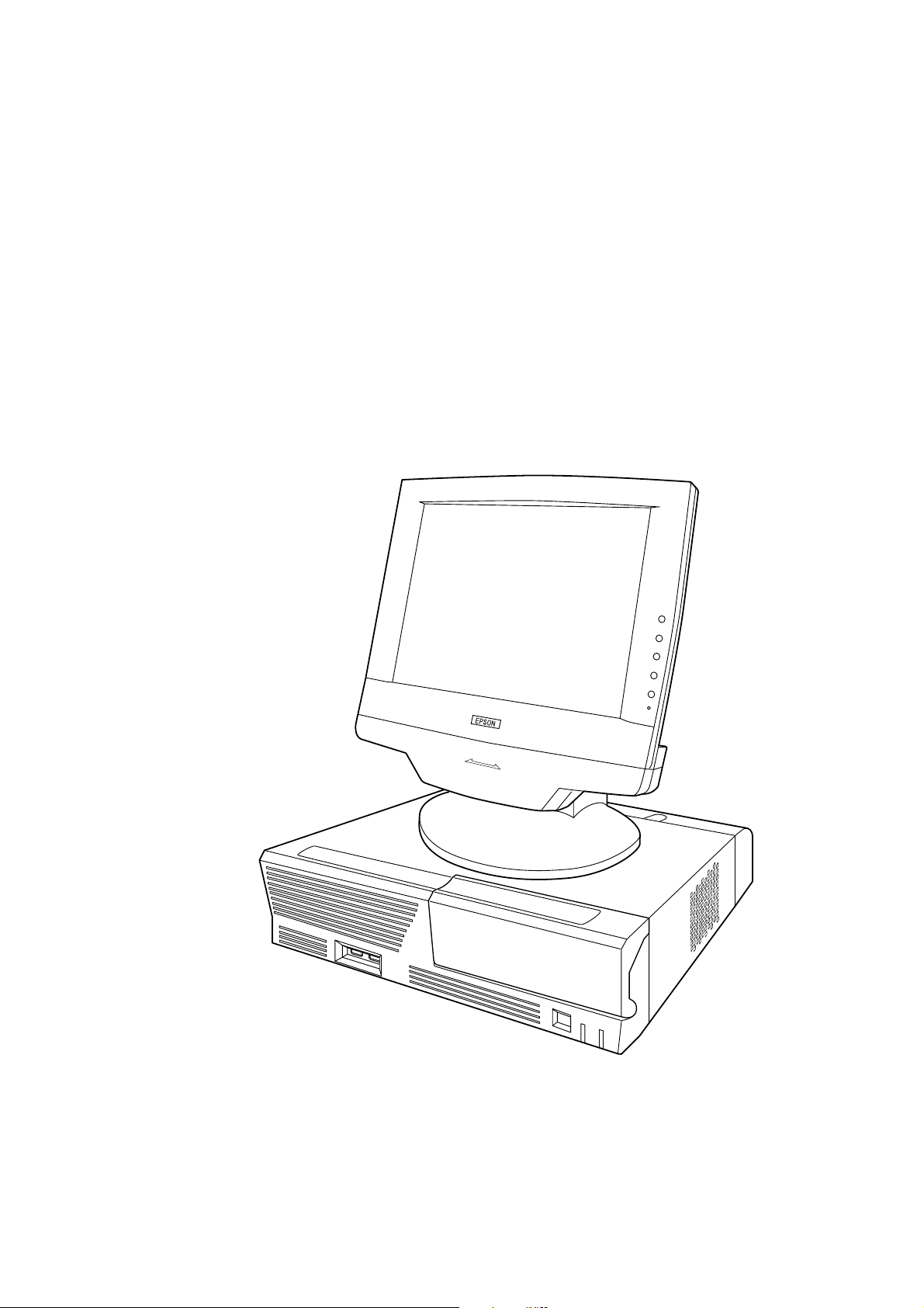
Features
The MR is a modular-type POS terminal consisting of a base unit, which is the IM-800, and a
display unit, which is the DM-M820. The IM-800 and the DM-M820 are also sold separately.
IM-800 Features
❏ IBM® PC/AT® compatible
®
❏ Intel
❏ Two 168-pin DIMM sockets are ready for installation of a maximum 512 MB of memory
❏ An LCD unit (DM-M820) exclusive to the MR can be connected
❏ A 3.5-inch floppy disk drive is available
Celeron™ (FC-PGA/FC-PGA2 package) can be used. Either a 733 MHz or a 1.2 GHz
Celeron is factory installed.
❏ A 3.5-inch hard disk drive or two 2.5-inch hard disk drive is available
❏ A CD-ROM drive or CD-R/RW drive is available as a factory option
❏ An Ethernet controller for 10Base-T/100Base-TX is installed as standard equipment
❏ Four serial interface ports are provided
❏ One PCI slot is provided
❏ A power supply for a TM printer is provided (For the 24V model)*1
❏ Cables on the rear of the IM-800 can be covered by the included cable cover
❏ A small footprint with maximum dimensions of 315 × 365 × 88 mm (W × D × H) {12.4 × 14.4
× 3.5"} (including rear cover)
*1 Applies only with the TM Printer Power Supply model.
DM-M820 Features
The DM-M820 is an LCD unit designed to be connected to an EPSON PC-POS system.
❏ 800 × 600 dots resolution using a 12.1 inch color TFT LCD
❏ A tilt mechanism for easy positioning of the screen viewing angle
❏ A cable cover or a unified cable performs cable management effectively
❏ Display settings of the LCD and the brightness of the backlight can be adjusted.
❏ A stain-resistant touch panel is used.*1
❏ Input by finger touch using the resistive film type of touch panel.*2
❏ An MSR unit can read ISO/JIS Track 1, 2, or 3 (only for models with an MSR unit) *3
Rev. I Features and Overview 1-1
Page 22

❏ Power is supplied from the IM-800 or the OI-MR01 AC Adapter. The AC Adapter is used if
the DM-M820 is bought by itself instead of with an IM-800.
*1 Applies only to models with a stain-resistant Touch Panel.
*2 Applies only to models with a Touch Panel.
*3 Applies only to models with an MSR, which is sold only with the IM-800.
Model Configurations
The MR is composed of the IM-800 and the DM-M820.
IM-800
CPU 733MHz, 1.2GHz
HDD One 3.5" HDD, Two 2.5" HDDs
CD-ROM drive CD-ROM drive, CD-R/RW drive, Without
Power Supply For the standardmodel 145W ATX Power supply
Power Supply Withe the TM Printer
Power Supply model
Speaker With, Without
Case Color Epson cool white, Epson dark glay
180W ATX Power supply with 24V
DM-M820
MSR With, Without
Touch Panel With, Without
Back light 2 lights*
Case Color Epson cool white, Epson dark glay
AC Adapter With sold only the DM-M820 model
* The OLD model has 1 light.
The IM-800 and the DM-M820 are sold separately, but the DM-820 model with MSR is sold only
with the IM-800.
1-2 Features and Overview Rev. I
Page 23
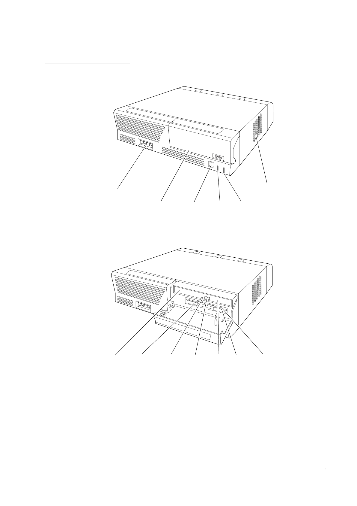
Part Names for IM-800
Front view
MR Series Technical Reference Manual
USB ports
CD/FDD
cover
With CD/FDD cover open
CD-ROM
drive(option)
FDD LED
CD-ROM
LED
Power
switch
CD-ROM
eject button
Power
LED
Eject
hole
HDD LED
FDD unit
Ventilation
opening
FDD eject
button
Rev. I Features and Overview 1-3
Page 24
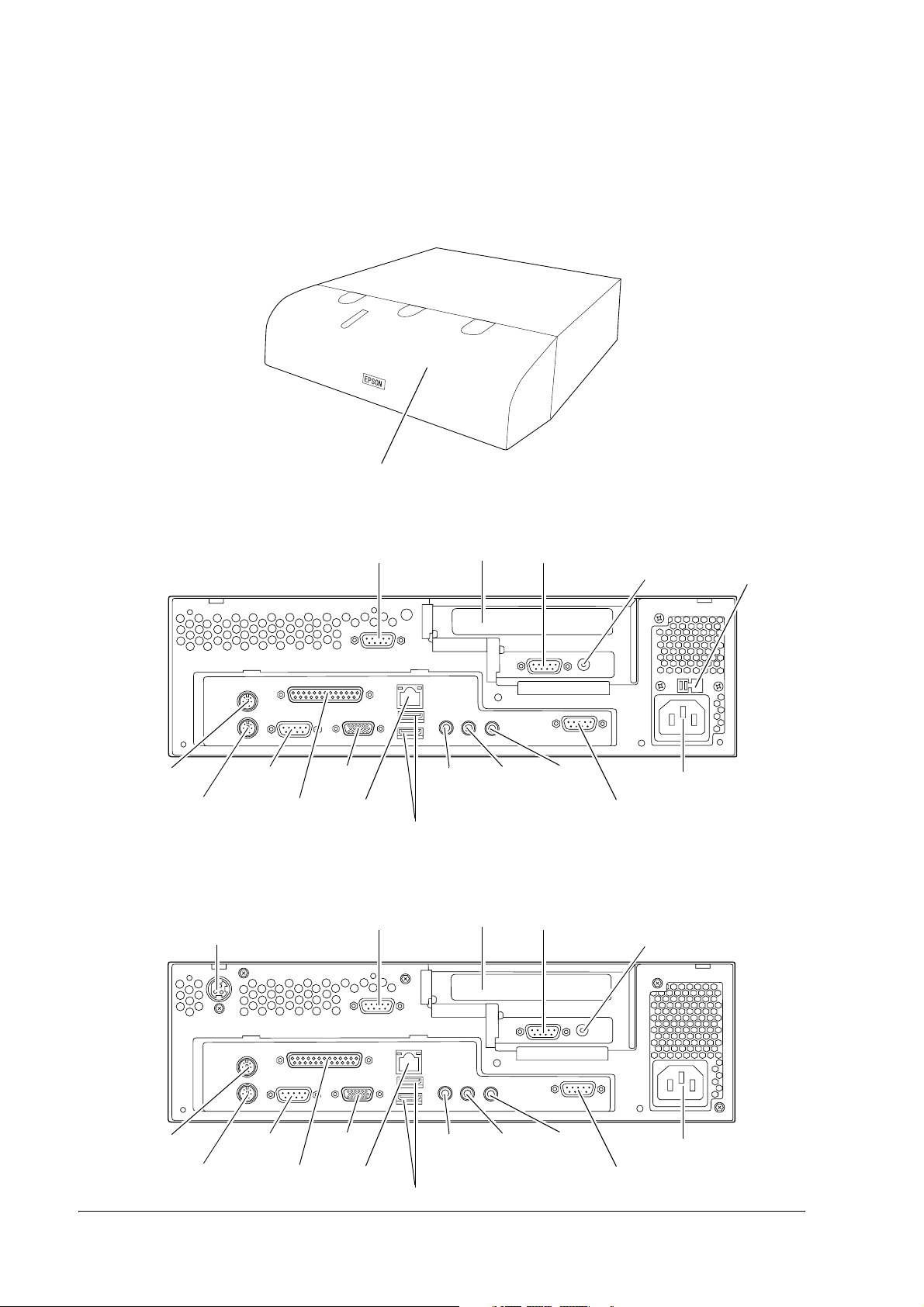
Rear Cover
Rear cover
Rear view(Standard model)
Mouse
Keyboard
COM1 port
LPT port
Rear view(24V model)
DC 24V output
(for TM printer)
COM2 port
Display
port
Ethernet
port
COM2 port
Line-out
output
USB port
PCI slot
PCI slot
COM3 port
Line-in
input
COM3 port
Mic input
DC 12V output
(for DM-M820)
COM4 port
DC 12V output
AC voltage
select switch
AC Inlet
Mouse
Keyboard
COM1 port
LPT port
Display
port
Ethernet
port
Line-out
output
USB port
Line-in
input
Mic input
AC Inlet
COM4 port
1-4 Features and Overview Rev. I
Page 25
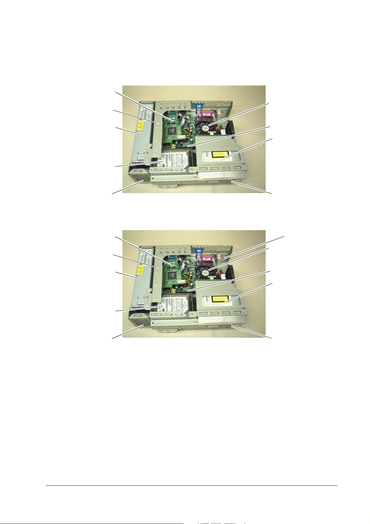
.
Inside view(for the Standard model)
COM Port Circuit
Board Assembly
PCI card
MR Series Technical Reference Manual
Rear Side
CPU
Power Supply
HDD
Speaker
(for the Speaker model)
Inside view(for the 24V model)
COM Port Circuit
Board Assembly
PCI card
Power Supply
DIMM
CD-ROM Drive
FDD
Front Side
Rear Side
DC 24V Board
CPU
DIMM
CD-ROM Drive
HDD
Speaker
(for the Speaker model)
Front Side
FDD
Rev. I Features and Overview 1-5
Page 26
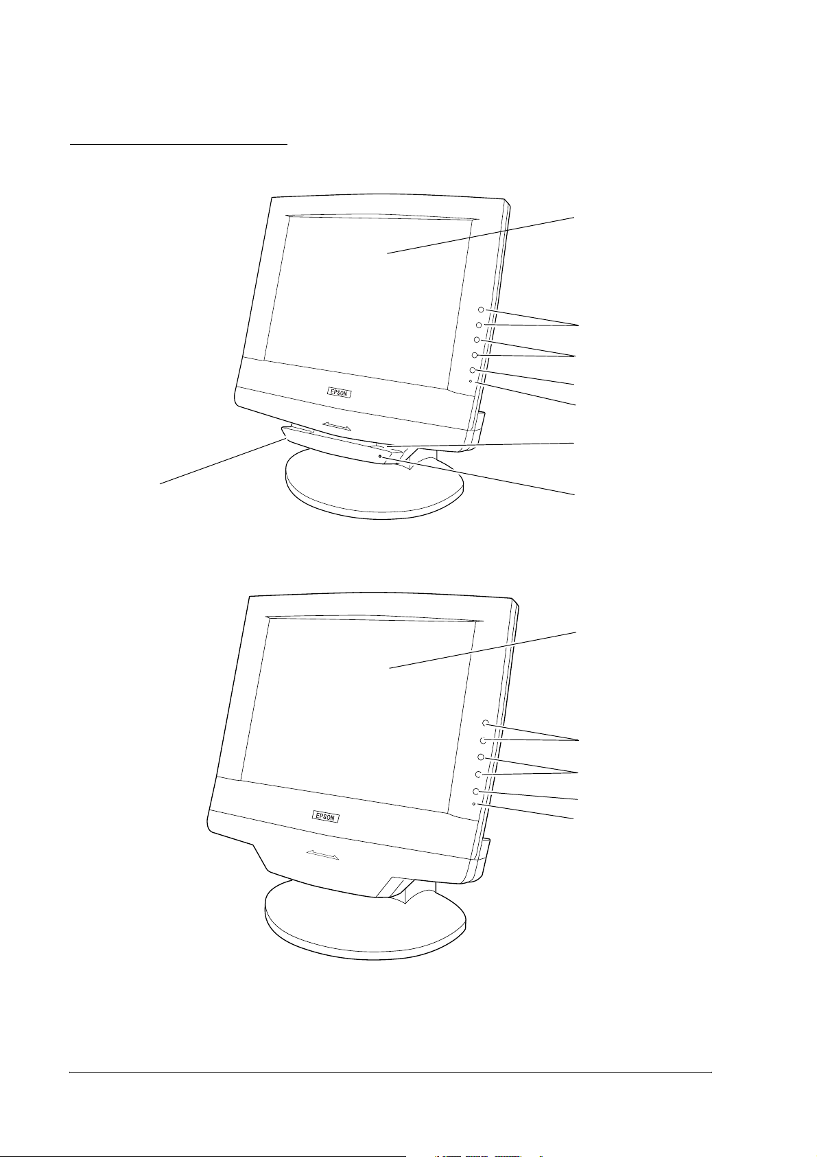
Part Names for DM-M820
Model with MSR
MSR unit**
Model without MSR
LCD / touch
panel*
Function
control buttons
Adjustment
control
Power switch
Power-On LED
Card Slot**
LED for MSR**
LCD / touch
panel*
Function
control buttons
Adjustment
control
Power switch
Power-On LED
1-6 Features and Overview Rev. I
Page 27
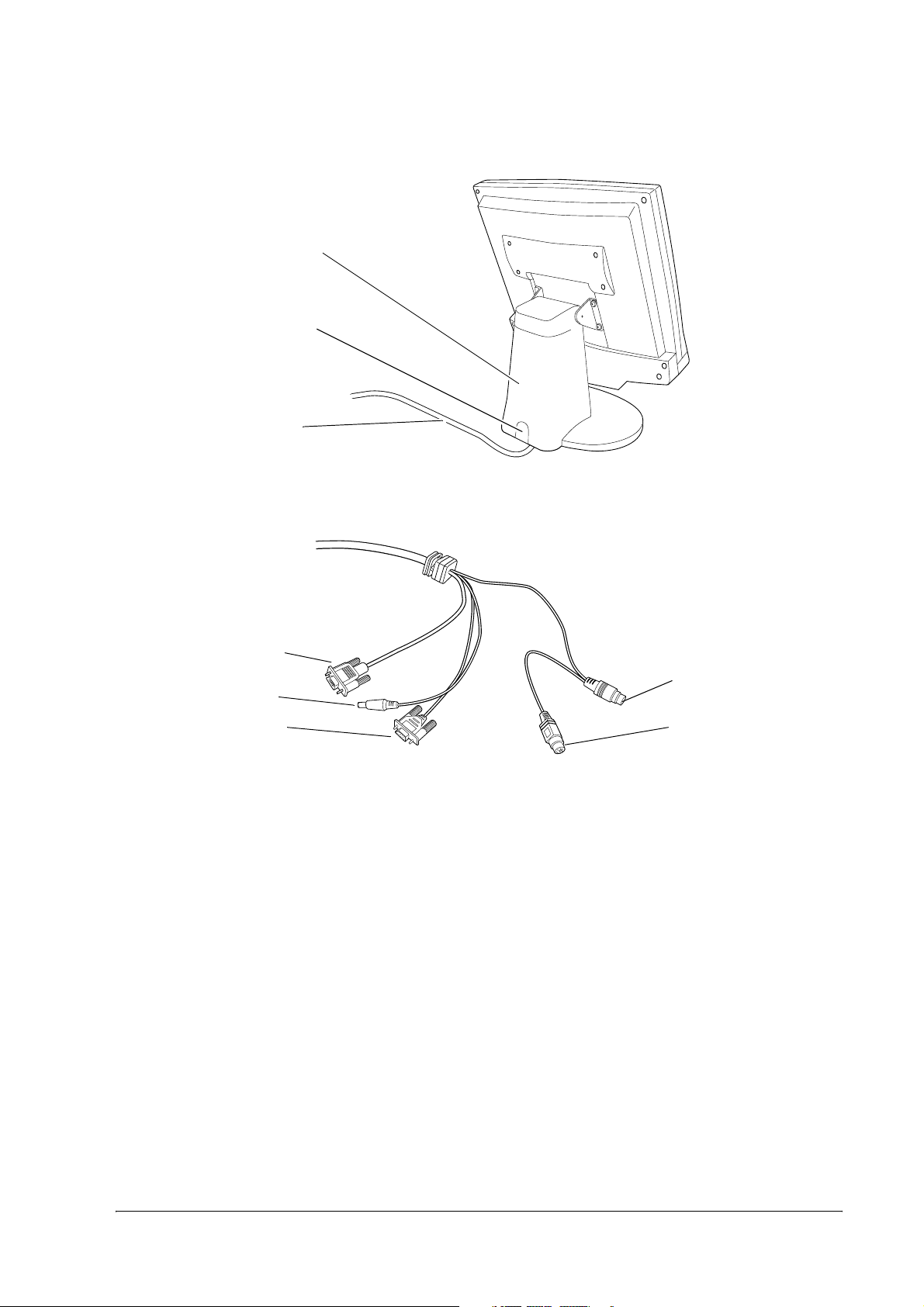
Rear view
LCD stand
Stand tab
Cable A /
Cable B /
Cable C /
Cable A (with a touch panel and an MSR)
MR Series Technical Reference Manual
Display
connector
DC plug
Serial port
connector
PS/2 keyboard
connector for IM-800
PS/2 keyboard
connector for keyboard
Rev. I Features and Overview 1-7
Page 28
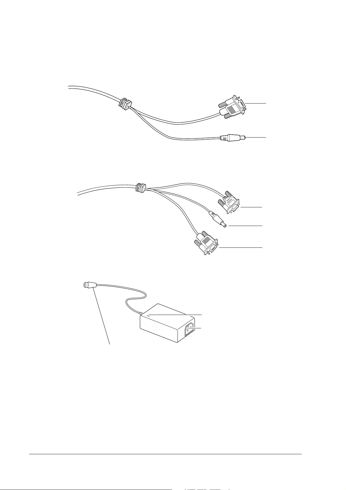
Cable B (without a touch panel and an MSR)
Cable C (with a touch panel, without an MSR)
Display
connector
DC plug
Serial port
connector
DC plug
Display
connecter
.
AC Adapter (OI-MR01)
DC plug
* Applies only to models with a touch panel.
** Applies only to models with an MSR.
Power LED
AC inlet
1-8 Features and Overview Rev. I
Page 29

MR Series Technical Reference Manual
Specifications
IM-800
Item Specifications
CPU Usable CPU types *1) Celeron 733 MHz or 1.2 GHz
Socket 370-pin socket
Memory Main memory *2) 168-pin DIMM slots × 2
BIOS ROM 512KB
Chipset Intel 810E2 chipset
Video controller Built-in chipset
IO controller Winbond W83627F (controls FDD, COM1/2, PS/2, and parallel
Mass storage FDD One 3.5" floppy drive (1.44MB / 720KB)
HDD One 3.5" HDD or Two 2.5" HDD
3.3V PC100 SDRAM / Maximum 512MB
interface)
ITE IT8872F (controls COM3/4)
IDE interface / Ultra DMA/33/66/100
CD-ROM drive A CD-ROM or CD-R/RW optionally installed in factory, IDE
Interface LAN (Ethernet) 10BASE-T/100BASE-TX is installed, "Wake On LAN" is
Interface Keyboard One PS/2-type (6-pin mini-DIN)
Mouse One PS/2-type (6-pin mini-DIN)
Serial *3) Four ports (9-pin D-sub male)
Parallel One port (D-sub 25-pin female) SPP/EPP/ECP supported
Display One port (D-sub 15-pin female)
USB *4) Two ports on the front and two ports on the rear.
Audio LINE IN, LINE OUT, microphone terminals
DC12V output *5) *8) One (+12V / 3A) for DM-M820
DC 24V output*8) One (+24V / 2A) for EPSON TM Printer
Expansion slot PCI slot One slot (PCI version 2.2 compliant)
Internal speaker *6) Built-in monaural speaker
Audio function *6) AC'97 audio CODEC supported
Backup battery For the Lithium non-rechargeable battery the RTC and the
BIOS ACPI 1.0b / APM 1.2 / Plug & Play / DMI
OS *7) MS-DOS, Windows 98, Windows NT, Windows 2000, Windows XP
interface, can be set as boot drive
supported.
+5V or +12V can be output to COM3 or COM4.
External line input/output, with a microphone terminal
RTC's built-in CMOS RAM when AC power is not supplied.
Battery type: CR2032
Battery life: Approximately 5 years
Diagnostics Utility are supported
Rev. I Features and Overview 1-9
Page 30

Item Specifications
Lithium battery The IM-800 is internally equipped with a Lithium non-rechargeable
Power supply Standard
model
Input voltage *8) AC input voltage can be changed with a switch.
battery that supplies the backup voltage to the RTC and the RTC's builtin CMOS RAM when AC power is not supplied. The battery can be
exchanged easily because the battery is connected through the
socket.
Battery type: CR2032
Battery life: Approximately 5 years
145W ATX power supply is built in
Low range: 100-127 VAC / 3.5 A (max.)
High range: 200-240 VAC / 2 A (max.)
Frequency 50 / 60 Hz
24V
model
Input voltage *8) 100-127 VAC / 4 A (max.)
180W ATX power supply is built in
200-240 VAC / 2 A (max.)
Frequency 50 / 60 Hz
Case Size 315(W) × 280(D) × 88(H) mm (excluding the rear cover)
{12.4 × 11 × 3.5"}
315(W) × 365(D) × 88(H) mm (including the rear cover)
{12.4 × 14.4 × 3.5"}
Color Epson cool white
Epson dark gray
Environmental
conditions
Condition: Operating range Storage range
Temperature: 5 to 35°C {41 to 95°F} –10 to 50°C {14 to 122°F}
Humidity (RH): 30 to 80% non-condensing 30 to 90% non-condensing
*1: The Celeron (533 MHz or less) with a PPGA package is not supported.
*2: ECC is not supported.
*3: If the COM3/4 is used, you need to install the serial driver from the Driver CD-ROM for the IM-800.
*4: The USB interface is not supported with MS-DOS, or Windows NT. (The keyboard or mouse is supported with the BIOS.)
*5: The LCD outlet must not be connected to a peripheral other than the DM-M820.·
*6: The internal speaker is not supported by the onboard sound controller.(There is a model that can output sound through the
internal speaker.)
*7: There are some limitations with each OS. Refer to Chapter 4 “OS and Drivers.”
*8: A switch to cut the AC power off is not available.
1-10 Features and Overview Rev. I
Page 31

MR Series Technical Reference Manual
DM-M820
Item Specification
LCD Size 12.1"
Type Color TFT
Resolution 800 × 600 dots
Color 262,144 colors
Input signal 0.7V p-p, 75 ohm
Scanning frequency Horizontal 24 to 69KHz, Vertical 50 to 85 Hz
Dot clock frequency Max. 80MHz
View angle Horizontal
direction
Vertical direction From the top 30º (typ.) to the bottom 10º (typ.)
Backlight Old Backlight
Standard model
Backlight
Standard model
(Old Backlight
High brightness
model)
Touch panel*1 Method Resistive film (touch with finger)
Surface solidity 3H or more (JIS K-5400)
Positioning accuracy ±1.5 % maximum
MSR*2 Supported cards ISO 7811, JIS X6301 Type
Reading direction Bidirectional
Supporting MSR firmware Ver 3.04 or later
External interface DC Jack, Serial port connector*1, Display connector,
Indicator With an MSR POWER LED, LED for MSR
Without an MSR POWER LED
AC Adapter POWER LED
Power supply +12V (supplied through the DC cable from the IM-800
Tilting angle From 0º to 90º
Case color Epson cool white
Dimensions 320 × 340 × 200 mm (W × H × D) {12.6 × 13.4 × 7.9"}
Number of lamps 1 lamp
Brightness 150 cd/m
Life
Number of lamps 2 lamp
Brightness 275 cd/m
Life
(Can emulate 16 M color display using the dithering
function)
From the left 45º (typ.) to the right 45º (typ.)
2
min. (except touch panel)
100 cd/m
20,000 hours or more (at 25 ± 5°C {77 ± 9°F})
Initial brightness reduced to half
50,000 hours or more (at 25 ± 5°C {77 ± 9°F})
Initial brightness reduced to half
PS/2 connectors × 2 (for a PS/2 keyboard and the IM-
800)*2
or AC Adapter OI-MR01)
Epson dark gray
2
min. (including touch panel)
2
min. (except touch panel)
I tracks 1, 2, 3
Rev. I Features and Overview 1-11
Page 32

Item Specification
Mass Approximately 5.0 kg {3.3 lb}
Environmental conditions Condition: Operating range Storage
Others Connection to the IM-800 through an exclusive DC
*1 Applies only to models with a touch panel.
*2 Applies only to models with an MSR unit.
range
Temperature: 5 to 35°C {41 to 95°F} –10 to 50°C
{14 to 122°F}
Humidity (RH): 30 to 80% non-condensing 30 to 90%
non-condensing
The unit is not water resistant.
cable.
A button on the right side of the panel lets you adjust
the backlight brightness.
AC Adapter (OI-MR01)*
Item Specification
Input 90 -264 VAC / 1.5 A (max.)
Frequency 47 -63 Hz
Output 12VDC / 3 A (max.)
Protection
function
Dimensions 110 × 62 × 33 mm (W × H × D) {4.3× 2.4 × 1.3"}
Over voltage protection
function
Circuit breaker Manual reset
Built-in
* The AC Adapter is used if the DM-M820 without MSR model is used without an IM-800.
1-12 Features and Overview Rev. I
Page 33

MR Series Technical Reference Manual
Dimensions
IM-800
Dimensions: 315 (W) × 280 (D) × 88 (H) mm {12.4 × 11 × 3.5"} (excluding the rear cover)
315 (W) × 365 (D) × 88 (H) mm {12.4 × 14.4 × 3.5"} (including the rear cover)
280
365
DM-M820
250 mm
88
(excluding the rubber feet)
[Units : mm]
315
340 mm
200 mm
305 mm
320 mm
Rev. I Features and Overview 1-13
Page 34

Underside of Base
The dotted circle is the position and size of the hole in the table required if the DM-M820 is
mounted on a table with the cable going down rather than out of the back of the LCD stand.
102
70
50
200
240
1-14 Features and Overview Rev. I
Page 35

MR Series Technical Reference Manual
Chapter 2
Setup for the IM-800 and the DM-M820
Setting the AC Voltage for the IM-800 (For the Standard model)
If you are using 100-127 V power, set the AC
voltage switch to 115. If you are using 200-240 V
power, set the AC voltage switch to 230. (The
factory setting is 230.) If the setting is wrong,
the system will be damaged and will not
operate.
Follow these steps:
1. Remove the warning sheet.
2. Set the AC voltage select switch.
IM-800 Installation Positions
You can install the unit in either of the positions shown.
The rubber feet are used only when the unit is installed
horizontally. Attach the rubber feet to the indentations on
the bottom of the unit.
WARNING:
If you set this product upright, be sure the ventilation opening is on the top. Do not place
any object on top of the ventilation opening. If the ventilation opening is blocked, the
product can be damaged by overheating.
If you install this product horizontally, never place any object within 3 cm {1.2"} of the
ventilation openings on the front, side, and rear. If the ventilation opening is blocked,
the product can be damaged by overheating.
Rev. I Setup for the IM-800 and the DM-M820 2-1
Page 36

If the IM-800 is placed horizontally with the rear cover installed, attach the rubber feet
that are included or leave at least 1 cm {0.4"} of space from the bottom of the rear
cover.
1cm or more
Installing face
Do not put anything that weighs more than 20 kg {44 lb} on the IM-800 when it is installed
horizontally.
Installing the DM-M820
Cable Arrangement
When you plan your installation of the DM-M820, consider the cable that comes out of the base.
There are two ways you can arrange the cable:
❏ Make a hole in the surface on which you will place the unit and run the cable through the
hole (A in the illustration below).
❏ Remove the tab from the back of the LCD stand and run the cable out of the back of the LCD
stand (B in the illustration below).
B
A
CAUTION:
If burrs are left after the tabs are removed, they may cause cuts or scratches. Remove
the burrs with a nipper or file.
2-2 Setup for the IM-800 and the DM-M820 Rev. I
Page 37

MR Series Technical Reference Manual
Connecting the DM-M820
Be sure to unplug the power cable for the IM-800 or PC before you connect the cables for the
DM-M820.
Connectors on the IM-800
Keyboard out
Serial port connectors
Display connector
Connector Cables for a DM-M820 with a Touch Panel and MSR
❏ DC plug Connects to the 12 VDC output of the IM-800.
❏ Display connector Connects to the display port of the IM-800.
❏ Serial port connector Connects to the touch panel COM1 or COM2 port.
Note:
If you are using a DM-M820 with a touch panel, be sure to connect the serial port connector to
COM1 or COM2. Do not use COM3 or COM4.
DC plug
Also if you are using a DM-M820 with a touch panel, do not install a mouse driver. Installing a
mouse driver can prevent the touch panel from working.
❏ Keyboard
out Connects the keyboard out to the IM-800 keyboard port.
Note:
Be sure not to connect to the mouse port.
❏ Keyboard
in If you are using an external PS/2 keyboard, connect it to the keyboard
in connector.
Connector Cables for a DM-M820 with a Touch Panel and without an MSR
❏ DC plug Connect to the 12 VDC output on the IM-800 or the AC adapter
(OI-MR01).
❏ Display connector Connect to the display port on the IM-800 or PC.
❏ Serial port connector Connect to the COM port for the touch panel on the IM-800 or PC.
Rev. I Setup for the IM-800 and the DM-M820 2-3
Page 38

Note:
If you are using a DM-M820 with a touch panel, be sure to connect the serial port connector to
COM1 or COM2. Do not use COM3 or COM4.
Also if you are using a DM-M820 with a touch panel, do not install a mouse driver. Installing a
mouse driver can prevent the touch panel from working.
Connector Cables for a DM-M820 with No Touch Panel and No MSR
❏ DC plug Connect to the 12 VDC output of the IM-800 or AC adapter
(OI-MR01).
❏ Display connector Connect to the display port of the IM-800 or PC.
Connecting the Power Cable for AC Adapter
Be sure to push the end of the power cable all the way into the AC inlet. The fitting on the power
cable should make contact with the back of the inlet.
CAUTION:
Do not use the DC plug on a system other than the IM-800 or the OI-MR01 (AC adapter).
The DC plug on the exclusive cable is designed only for the IM-800 or the OI-MR01 (AC
adapter).
IM-800 Connectors
The illustration below shows all the connectors on the back of the IM-800. In addition, there are
two USB connectors on the front. (See Chapter 1.)
Be sure to unplug the power cable from the IM-800 before you connect these cables.
Standard model
Mouse
Keyboard
COM1
LPT
COM2
Display
Ethernet
PCI slot
Line-out
USB
COM3
Line-in
Mic input
12 VDC output
for DM-M820
AC Inlet
COM4
2-4 Setup for the IM-800 and the DM-M820 Rev. I
Page 39

With the TM Printer Power Supply model
MR Series Technical Reference Manual
Mouse
Keyboard
COM1
LPT
COM2
Display
Ethernet
PCI slot
Line-out
USB
COM3
Line-in
Mic input
COM4
Connecting Other Peripheral Devices to the IM-800
These are general instructions for the types of peripherals you may want to use.
CAUTION:
12 VDC output
for DM-M820
AC Inlet
The12 VDC output is an exclusive power supply for the DM-M820. Do not use it for other
peripheral devices.
Serial Device Information
If you use COM3 or COM4, you must install the serial driver from the driver CD-ROM for the
IM-800, included with the IM-800.
Either + 5 V or +12 V can be output to COM3 or COM4. See Appendix A, “Jumper Settings.”
Connecting a Serial Modem to the IM-800
If you are using a serial modem with the IM-800, be sure to connect the modem to COM1 or
COM2. Do not use COM3 or COM4.
USB Device Information
There are four USB ports, two on the front and two on the back.
You cannot use USB devices if you are using either MS-DOS or Windows NT.
Rev. I Setup for the IM-800 and the DM-M820 2-5
Page 40

Keyboard and Mouse
To use a USB keyboard or mouse under MS-DOS or Windows NT, set USB keyboard support or
USB mouse support in the Integral Peripheral section of the BIOS setup.
Using a PS/2 mouse
To use a PS/2 mouse, you must be sure that USB mouse support in the Integrated
Peripheral section of the BIOS is set to Disabled (which is the factory setting).
TM-Printer
Use the dedicated power supply for the power supply of the TM-Printer. (For the standard
model)
Connect the power supply of the TM-Printer to the DC24V Output using the DC cable. (For the
24V model)
PCI Cards
See the PCI information in Chapter 3, “Hardware Specifications,” and Chapter 9, “Disassembly
and Assembly.”
Connecting the Power Cable
When AC power is supplied, a minute electric current flows through the IM-800. Therefore,
before connecting peripherals and cables to this product, unplug the AC cord.
WARNING:
Never insert or disconnect the power plug with wet hands. Doing so may result in severe
shock.
Always supply power directly from a standard domestic power outlet.
Do not place multiple loads on the power outlet (wall outlet). Overloading the outlet
may lead to fire.
The equipment must be installed near the electrical outlet, and the outlet must be easily
accessible.
Be sure your power cable meets the relevant safety standards and includes a power
system ground terminal (PE terminal).
2-6 Setup for the IM-800 and the DM-M820 Rev. I
Page 41

MR Series Technical Reference Manual
Attaching the Rear Cover
The rear cover makes the back of the system look neat and protects the cables.
1. When you want the cables to exit the top of the rear cover, use pliers to break out the tabs.
CAUTION:
If burrs are left after the tabs are removed, they may cause cuts or scratches.
Remove the burrs with a cutter or file.
2. Remove the screw from the lower right corner of the back of the unit.
3. Fit the tabs on the rear cover as shown below.
tabs
4. Attach with three screws, including the one you removed, in the locations shown below.
Rev. I Setup for the IM-800 and the DM-M820 2-7
Page 42

2-8 Setup for the IM-800 and the DM-M820 Rev. I
Page 43

Chapter 3
y
r
Hardware Specifications
Hardware Block Diagram for IM-800
I2C Bus
RTC
Battery
RJ-45
& LED
Clock
Generator
ICS9248-9
66/100/133 MHz
S-DRAM
PC100
DIMM 168
Pins X 2
I2C Bus
PHY
82562ET
CPU
Socket 370
HOST Bus
810E
GMCH
(North Bridge)
82810E
Hub Link
ICH2
(South Bridge)
FW82801BA
MAC
MR Series Technical Reference Manual
Main Board
VRM 8.5
DC/DC
ISL6524
USB Port 0
USB Port 1
USB Port 2
USB Port 3
PCI Bus PCI Bus
HDD Power
FDD Power
CD Power
DC Jack Power
VGA
CRT
USB
USB
Pin
Header
ATX Power
Supply Unit
ATX 20 Pins
Power Connector
Power Button
Power/HDD LED
BOX Header
Rear
USB
Front
USB
24V
Output
MIC
L_Out
L_In
Keyboard
Mouse
COM1
COM2
CODEC
AD1887
FWH (BIOS)
Firmware Hub
512K Byte
49LF004
/ 82802AB
FWH
LPC Interface
PS-2 Keyboard
PS-2 Mouse
COM 1
COM 2
AC Link
LPC
Super I/O
Winbond
W83627F
QFP-128
ATA-33/66/100
IDE
Primar
Secondary IDE
SPKR
Beep
Floppy
Parallel
1st IDE
2nd IDE
Speaker
FDD
LPT
CPU Fan
System Fan
Riser Board Slot
Low Profile
PCI Slot
+12V
+5V
ITE
PCI
Bridge
IT8872F
+12V
+5V
+12V
Riser Board
Standard
PCI Slot
COM Board
COM 3
COM 4
DC
Jack fo
LCD
Rev. I Hardware Specifications 3-1
Page 44

DMA
The IM-800 supports seven DMA channels. Channels 0, 1, 2, and 3 provide 8-bit data transfers;
channels 4, 5, 6, and 7 provide 16-bit data transfers. The IM-800 uses channel 2 for the floppy
disk drive controller and releases the other channels to the other devices. The following table
lists the DMA channel allocation.
DMA channels
Controller Channel Application
DMA1 8 bits 0 (Spare)
1(Spare*)
2 Floppy disk drive controller
3(Spare*)
DMA2 16 bits 4 Controller 1 cascade
5(Spare)
6(Spare)
7(Spare)
* When LPT1 is in ECP mode, use one of these channels.
System Interrupts
The system connects 2 8259A-equivalent interrupt controllers in cascade and has 15 levels of
interrupts, besides NMIs. The following table shows the application for each interrupt. Change
the system interrupts with the BIOS setup program or Plug & Play function.
System interrupts
Controller 1 Controller 2 Application Changeable?
IRQ0 Timer NO
IRQ1 Keyboard NO
IRQ2 Controller 2 cascade NO
IRQ8 RTC NO
IRQ9 Not used *
IRQ10 Not used *1 OK
IRQ11 Not used *
IRQ12 Mouse NO
IRQ13 Numerical operation coprocessor NO
IRQ14 IDE controller (primary) *
IRQ15 IDE controller (secondary) *
IRQ3 Serial port 2 OK
IRQ4 Serial port 1 OK
IRQ5 Not used *
IRQ6 Floppy disk controller NO *
IRQ7 Parallel port 1 OK
NMI I/O error check NO
*1 PCI (for example, network) is automatically set through the detection of the unused interrupt level. If Serial port 3/
4 is used with Windows, use an unused interrupt level. If Serial port 3/4 is used with DOS, Serial port 3 is set to IRQ11
and Serial port 4 is set to IRQ10 automatically.
2
Changes are not possible when the device is in use, but can be cleared when not in use.
*
3
This can be set to “Not used” in the BIOS setup, but the IRQ is not released.
*
1
1
1
OK
OK
2
2
OK
3
3-2 Hardware Specifications Rev. I
Page 45

Configuration of Circuit Boards
Main Board
MR Series Technical Reference Manual
Mouse
Keyboard
Parallel
COM1
CRT
LAN
USB x2
Line-Out
Line-In
Mic-In
COM2
Header
CPU Fan
Connector
CPU
Socket
(370-pin)
System Fan
Connector
ATX Connector
DIMM Sockets
Power Switch
Connector
LED
Connector
BIOS
FDD
Secondary IDE
Primary IDE
CD Audio
Header
Speaker
Connector
JP15
Riser Card Slot
Front USB
Header
JP10
Speaker
COMS CLEAR Jumper
RTC Battery
Rev. I Hardware Specifications 3-3
Page 46

Riser Board
COM Board
COM Board Slot
DC12V Input
Connector
PCI Slot
JP2
JP1
COM4
Header
DC12V
COM3
Jack
DC24V Board
DC24V Jack
DC24V Input
Connector
PCI Slot
CAUTION:
Before using a PCI card, it is your responsibility to examine it carefully to confirm whether
its specifications conform to the specifications described in this manual.
To get the latest information about which PCI board can be used with this product,
contact your EPSON dealer.
The PCI slot is located on the riser board.
3-4 Hardware Specifications Rev. I
Page 47

The dimensions of installable PCI cards are shown below:
210
MR Series Technical Reference Manual
<Part mounting face>
Maximum height of parts: 14.48
(maximum)
Maximum height of parts on the soldering face:
2.67 (maximum)
106.68
[Units:mm]
Power Supply
The IM-800 has an ATX power supply that switches the AC input by AC voltage select switch
and does not have a switch to cut off the AC input.
Standard model
Input voltage: Low range 100 - 127 VAC (90 - 137 VAC)
High range 200 - 240 VAC (180 - 265 VAC)
Input frequency: 50 ± 3 Hz / 60 ± 3 Hz
Input current: 3.5 A maximum (100 - 127 VAC)
2 A maximum (200 - 240 VAC)
Cooling fan: Air intake type, fan rotation speed is automatically changed, depending on
the temperature in the power supply unit.
MTBF: 200,000 hours
Precautions:
1) Setting the AC input voltage switch improperly causes the following problems:
If you use 100-127 V power when the switch is set to 230, the IM-800 will not operate, but if you
change the setting to 115, the unit will operate.
If you use 200-240 V power when the switch is set to 115, the voltage power unit will be
damaged.
2) When the protective circuit of the voltage power unit performs a shutdown, the protective
circuit keeps working for a while. When this happens, unplug the power cable and wait for
about 15 seconds; then plug the cable back in.
Rev. I Hardware Specifications 3-5
Page 48

24V model
Input voltage/current: 100 - 127 VAC / 4A
200 - 240 VAC / 2A
Input frequency: 50 ± 3 Hz / 60 ± 3 Hz
Cooling fan: Air intake type, fan rotation speed is automatically changed,
depending on the temperature in the power supply unit.
MTBF: 200,000 hours
Precautions:
2) When the protective circuit of the voltage power unit performs a shutdown, the protective
circuit keeps working for a while. When this happens, unplug the power cable and wait for
about 15 seconds; then plug the cable back in.
Power supply capacity for external devices
Total power available to devices connected to the interface boards in the PCI slot, COM3/4,
keyboard/mouse, and USB are as follows. Current drain must not exceed the capacity shown
for each supply voltage: +5V, +3.3V, +12V, and -12V.
Power supply Used for Capacity
+5 VDC PCI slot, COM ports, keyboard/mouse, USB 2.0 A
+3.3 VDC PCI slot 1.0 A
+12 VDC PCI slot, COM ports 1.0 A
-12 VDC PCI slot 0.02 A
Each port has the following current limitation:
Power Supply Capacities to Each Port
Port Voltage Current supply capacity Remarks
COM port +5 VDC 500 mA each (peak 1 A/100 ms) Total current of +5
+12 VDC 500 mA each (peak 1 A/100 ms)
USB port +5 VDC 500 mA each (peak 1 A/100 ms) --
Keyboard and mouse +5 VDC 500 mA (peak 1A / 100 ms) --
Power Supply for 24V model +24 VDC 2A (peak 1A / 100 ms) --
VDC and +12 VDC
must not exceed the
value shown at left.
3-6 Hardware Specifications Rev. I
Page 49

MR Series Technical Reference Manual
Lithium Battery
The IM-800 is internally equipped with a Lithium non-rechargeable battery, which supplies the
backup voltage to the RTC and the RTC's built-in CMOS RAM (only when the AC power is not
supplied). The battery can be exchanged easily because the battery is connected through the
socket.
Battery type: CR2032
Vendor: Sony, Maxell, Toshiba
Battery life: Approximately 5 years
When replacing batteries, be sure to use the types and manufacturers listed above.
MAC Address
The MAC address label is attached on the LPT connector of the main board.
Rev. I Hardware Specifications 3-7
Page 50

3-8 Hardware Specifications Rev. I
Page 51

MR Series Technical Reference Manual
Chapter 4
OS and Drivers
Outline of This Chapter
This chapter tells which Operating Sytems and Drivers can be used and how to install and
uninstall them.
CAUTION:
Don’t write anything, such as an application to an HDD that is removed from the MR.
The vibration and impact can cause trouble and the failure of the HDD.
Operating Systems
The following Operating Systems can be used for the IM-800.
❏ Windows 2000 Professional (There is a version preinstalled by EPSON)
❏ Windows XP Professional
❏ Windows 98SE (There is a version preinstalled by EPSON)
❏ Windows NT Workstation 4.0 SP6a
❏ MS-DOS Ver.6.22
Drivers and Utilities
Drivers for using the IM-800 are on the Driver CD-ROM included with the IM-800. If the
operating system is pre-installed, the drivers are also installed.
MSR utilities for the DM-M820 with MSR are on the Driver CD-ROM included with the IM-800,
and if the operating system is pre-installed, the utilities are on the HDD. Set up the MSR using
the utilities.
Touch panel drivers for the DM-M820 with touch panel are on the touch panel driver CD-ROM
for the DM-M820. Even if the operating system is preinstalled, you must install the touch panel
drivers.
Rev. I OS and Drivers 4-1
Page 52

Driver CD-ROM for the IM-800
The driver for installing a locally procured OS on the IM-800, the MSR utility for using the MSR
of the DM-M820, and drivers for using the peripheral devices are on this CD-ROM.
The CD-ROM directory is shown below.
Root CDVER.TAG
|--- DOS62 Drivers for MS-DOS
| |--- Cdrom : CD-ROM drivers
| |--- Network : Network drivers
| |--- Serial : Serial drivers
|--- WIN98 Drivers for Windows98
| |--- Chipset : Chipset drivers
| |--- Network : Network drivers
| |--- Serial : Serial drivers
| |--- Sound : Sound drivers
| |---Video : Video drivers
|--- WINNT Drivers for Windows NT
| |--- Network : Network drivers
| |--- Serial : Serial drivers
| |--- Sound : Sound drivers
| |---Video : Video drivers
|--- WIN2K Drivers for Windows2000
| |--- Chipset : Chipset drivers
| |--- Network : Network drivers
| |--- Serial : Serial drivers
| |--- Sound : Sound drivers
| |---Video : Video drivers
|--- WINXP Drivers for Windows XP
| |--- Serial : Serial drivers
|--- COMMON Common OS utility drivers
|--- Apdrv : Advanced Printer Drivers
|--- Oposadk : OPOS-ADK
|--- TmDrv : UniMini Drivers
|--- MSRCFG : DM-MS Definition tool
|--- WIN :
|--- DISK1 :
|--- DOS :
Readme.txt files are in both the root directory and in subdirectories of the root directory.
1. The Readme.txt file in the root directory contains an overview of this CD-ROM, and
refers to the Readme.txt files in the various subdirectories.
2. The Readme.txt files in the operating system subdirectories explain driver installation/
un-installation for each operating system.
3. Readme.txt files for MSRCFG, OPOS-ADK, and APDRV are included with the software.
4-2 OS and Drivers Rev. I
Page 53

MR Series Technical Reference Manual
Touch Panel driver CD-ROM for the DM-M820 touch panel model
The CD-ROM directory is shown below.
Root CDVER.TAG
|--- DOS Touch Panel Driver for MS-DOS
|--- WIN--- European Touch Panel Driver for Windows98/NT/2000/XP for European
|--- Asian Touch Panel Driver for Windows98/NT/2000/XP for Chinese T/
C,Korean
Readme.txt files are in both the root directory and in subdirectories beneath the root directory.
1. The Readme.txt file in the root directory contains an overview of this CD-ROM, and
refers to the Readme.txt files in the various subdirectories.
2. The Readme.txt files under the operating system subdirectories explain driver
installation/un-installation for each operating system.
Rev. I OS and Drivers 4-3
Page 54

Windows 2000 Pre-Installed Model
The exclusive EPSON utility and drivers for using IM-800 are pre-installed in the HDD with the
pre-installed Windows 2000 Professional.
Installation Procedure
Windows 2000 Installation
When turning on the power supply, the installation starts. Enter the product
key of the W2K label pasted on the product. You can set up the Network
automatically or set it up later.
When using the DM-M820 with Touch Panel, follow the steps as below.
Touch Panel Driver Installation
Install the Touch Panel Driver from the CD-ROM for the DM-M820. See
page 4-45 for the procedure.
Change of Double click settings
Set up this setting every time a new user starts using Windows 2000.
MSR Utility Installation
When using the DM-M820 with MSR, install the MSR utilities from
C:\backup\msrcfg folder or the Driver CD-ROM for the IM-800.
Other software Installation
When using OPOS-ADK, APD (Windows printer drivers) and Unimini,
install the software from the Driver CD-ROM for the IM-800.
Formatting the hard disk
The hard disk is composed of one partition of up to 10 GB as a system area. For a hard disk of
more than 10 GB, the excess area other than the system area, is not yet formatted. This drive can
be converted to NTFS using the Convert command. Use the disk administrator when creating a
drive in the unused area. The start-up drive has been formatted to the following file system.
• File system: FAT32
• Volume label: Windows 2000
4-4 OS and Drivers Rev. I
Page 55

MR Series Technical Reference Manual
Pre-installed software
❏ Microsoft Windows 2000 Professional
❏ Microsoft Windows 2000 Service Pack 2
❏ Multilingual User Interface (French, German, Italian, Spanish, Dutch, Portuguese)
❏ Intel Chipset software installation utility
❏ Intel Video driver
❏ Intel Network driver
❏ Analog Devices Sound driver
❏ ITE COM3/4 Driver
❏ EPSON DM-MS Series setup utility *1
Version of the Pre-installation HDD
To confirm the version of the HDD, see the file HDVER.TAG at the root directory of the boot
drive. This file is text-formatted and can be read using Notepad or a similar text editor. The file
HDVER.TAG has the following contents:
[HD Information]
MODEL=IM-800
OS=Windows2000
LANG=Dutch/English/French/German/Italian/Portuguese/Spanish
VER=1.**.*
Rev. I OS and Drivers 4-5
Page 56

Directory Configuration
The root directory of the HDD is structured as follows.
|--- Backup
| |--- Msrcfg : Backup of MSR Utility
| | |--- Win :
| | | |--- Disk1 : Backup of MSR Utility for Windows
| | |--- DOS : Backup of MSR Utility for MS-DOS
| |--- Chipset : Chipset driver backup folder
| | |--- Win2000 :
| |--- Network : Network driver backup folder
| |--- Recovery : Recovery folder
| |--- Serial : Serial port driver backup folder
| |--- Sound : Sound driver backup folder
| |--- Video : Video driver backup folder
| |--- Win2ksp2 : Windows 2000 Service Pack 2 backup folder
|--- BOOTDISK : Folder for files used to create an ordinary boot floppy disk
|--- Documents and Settings: Folder for saving text and settings.
|--- I386 : Setup file folder
|--- Mui :
|--- Program Files : Windows utility folders
|--- WINNT : Windows folders
The I386 directory may be deleted after the addition of the Windows 2000 application and the
addition / change of the driver.
The directories under the Backup directory are the backups for drivers and utilities. Each of
these directories can be backed up into CD-R or other media. After being backed up, these
directories may be deleted.
Windows 2000 Setup Procedure
CAUTION
Because the touch panel is not operative during the setup procedure, be sure to keep
the keyboard connected. If necessary, start the setup procedure after connecting the
mouse.
The keyboard is necessary for inputting the product ID and password. The keyboard is
also necessary for user verification during logon to Windows 2000, even if the touch
panel is in a usable state.
Windows 2000 is setup by using the following procedure.
1. Turn on the system, and boot the system from the pre-installation HDD. Windows 2000
setup will start.
2. The License Agreement screen is displayed. Check the contents, then select [I accept this
agreement] and click Next.
4-6 OS and Drivers Rev. I
Page 57

MR Series Technical Reference Manual
3. The Regional Settings screen is displayed. Make sure the system locale, user locales and
keyboard layout are set to United States, then click Next.
4. The Personalize Your Software screen is displayed. Input the Name and Organization, then
click Next.
5. The Your Product Key screen is displayed. Input the product key entered on the cover of the
First Step Guide in the COA (Certificate of Authenticity) package included with this
product; then click Next.
6. The Computer Name and Administrator Password screen is displayed. Input the Computer
Name and Administrator Password, then click Next.
7. The Date and Time Settings screen is displayed. Set the date and time, then click Next.
8. The Networking Settings screen is displayed. Select either Typical Settings or Custom
Settings according to the environment, then click Next. The Networking Components screen
is displayed if Custom Settings is selected. Set the settings in accordance with the
environment, then click Next.
9. The Workgroup or Computer Domain screen is displayed. Set the settings in accordance
with the environment, then click Next.
The Performing Final Tasks screen is displayed, and setup starts.
10. The Completing the Windows 2000 Setup Wizard screen is displayed. The system will start
automatically when Finish is clicked.
11. The Network Identification Wizard starts. Click Next.
12. The Users of this Computer screen is displayed. Set the settings in accordance with the
environment, then click Next.
13. The Completing the Network Identification Wizard screen is displayed. Click Finish.
14. Windows 2000 starts and the setup is completed.
CAUTION:
The setup is executed with the VGA display.
Change of double click settings
When you set up Windows 2000 and create a new user, you have to modify the registry key for
individual users by following the steps below.
Note
The touch panel driver is not installed with the Operating System. After installing it from the touch panel
driver CD-ROM for the DM-M820, set it up as follows.
1. Select Programs - Gunze - U-TP - Settings in that order from the Start menu.
Rev. I OS and Drivers 4-7
Page 58

2. Pointer Device Properties is displayed. Click the Windows tab.
3. Click the Defaults button on the Double Click Settings group box.
4. Click OK.
Installing the MSR Utility for Windows
Install the MSR Utility by the following procedure.
1. Start C:\Backup\Msrcfg\ Win\Disk1\SETUP.EXE.
2. The Setup Wizard starts and the Welcome dialog box is displayed. Click Next.
3. The Choose Destination Location dialog box is displayed. Specify the directory where the
program is to be installed and click Next. C:\Program Files\MSR Config is specified as the
default.
4. Installing is completed, and the Setup dialog box is displayed. Click Finish.
Uninstalling the MSR utility for Windows
Uninstall the MSR Utility by the following procedure.
1. Select [Start Menu] - [Settings] and open the control panel.
2. Select [Add/Remove Hardware] in the control panel.
3. Select [DM-MS Series Configuration Utilities].
4. Click Add/Remove.
5. The confirmation dialog box of the uninstalling is displayed. Select Yes.
6. Uninstalling is completed, and the dialog box is displayed. Click OK.
4-8 OS and Drivers Rev. I
Page 59

MR Series Technical Reference Manual
Recovering the OS
Use the OS recovery media (CD-ROM) packed with the IM-800 to recover the OS.
Follow the steps below to carry out OS recovery.
1. Turn power to the IM-800 off. Turn the main power switch off. Unplug the power cable.
2. If a CD-ROM drive is not already installed, attach a drive to the MR series.
3. Attach to the MR series the HDD unit you'd like to recover.
4. Start up the BIOS setup utility and select the First Boot Device from the Advanced BIOS
features setup menu.
5. Set the First Boot Device to “CDROM”.
6. Insert the “Windows 2000 CD-ROM 1 of 2" into the CD-ROM drive.
7. On the BIOS setup utility main menu, select “Save & Exit Setup” and press the Enter key.
The following dialog box appears.
SAVE to CMOS and EXIT (Y/N)?
8. Press [Y] and [Enter]. The system will restart and after a short time, the License Agreement
will appear.
Strike a key when ready ... _
9. When you press any key, part of the License Agreement will appear. Repeat the same
procedure until you get to the end of the License Agreement. The following message will
appear.
Please type following commands to start the OS recovery.
A:\>_
10. Enter the following from the command prompt.
A:\>x: [enter]
X:\>start [enter]
11. The following message will appear. Select and enter the partition size of the HDD.
Please select the system partition size.
1: 10GB (Default size)
F: Full size of HD.
Please push a key of 1 or F._
12. EPSON HDD Recovery Utility window will appear. Press Continue to start the OS
recovery.
OS recovery takes 20 to 40 minutes. The time differs depending on the type of OS and CPU
speed.
Rev. I OS and Drivers 4-9
Page 60

13. The image data exchange dialog will appear. Insert the Windows 2000 CD-ROM 2 of 2 in the
CD-ROM drive; then press the OK button.
14. When the prompt below is displayed on the screen, OS recovery work is complete.
X:\>_
15. Eject the “Windows 2000 CD-ROM” from the CD-ROM drive.
16. Reboot and start the BIOS setup utility.
17. Return the First Boot Device in the Advanced BIOS features setup menu to the “Floppy”.
18. On the main menu, select “Save & Exit Setup” and press the Enter key. The following dialog
box appears.
SAVE to CMOS and EXIT (Y/N) ?
19. Press [Y] and [Enter]. The system will restart.
20. Make sure the OS restarts. When using Windows, cancel work after the setup screen and
end Windows.
21. If a CD-ROM drive unit is attached in step 2., power off and detach the CD-ROM drive.
Limitation
❏ If you are starting from a hard disk, recovery cannot be performed. Be sure to perform
recovery from the CD-ROM.
4-10 OS and Drivers Rev. I
Page 61

MR Series Technical Reference Manual
Windows 98 Pre-Installed Model
The HDD pre-installed with Windows 98 Second Edition is also pre-installed with the EPSON
utility software and drivers dedicated to the IM-800.
Languages are English, French, German, Spanish, and Italian.
Installation Procedure
Windows 98 Installation
When turning on the power supply, the installation starts. Enter the product
key of the W98 label pasted on the product. You can setup the Network
automatically or setup it later.
Touch Panel Driver Installation
In the case of the DM-M820 with Touch Panel, install the Touch Panel Driver
from the CD-ROM for the DM-M820. See page 4-45 for the procedure.
MSR Utility Installation
When using the DM-M820 with MSR, install the MSR utilities from
C:\backup\msrcfg folder or the Driver CD-ROM for the IM-800
Other software Installation
When using OPOS-ADK, APD (Windows printer drivers) and Unimini,
install the software from the Driver CD-ROM for the IM-800.
Formatting the hard disk
The hard disk is composed of one partition of up to 10 GB as a system area. For a hard disk of
more than 10 GB, the excess area other than the system area is not yet formatted. Use the FDISK
and FORMAT command when creating a drive in the unused area. The start-up drive has been
formatted to the following file system.
• File system: FAT32
• Volume label: Windows 98
Pre-installed software
❏ Microsoft Windows 98 Second Edition
❏ Intel Chipset software installation utility
Rev. I OS and Drivers 4-11
Page 62

❏ Intel Video driver
❏ Intel Network driver
❏ Analog Devices Sound driver
❏ ITE COM3/4 Driver
❏ EPSON DM-MS Series setup utility *1
Note:
*1: These are not installed during the auto installation procedure.
Version of the pre-installation HDD
To confirm the version of the HDD, see HDVER.TAG in the start-up drive root. This file is textformatted and can be read using Notepad or a similar text editor. The contents of HDVER.TAG
are as follows:
[HD Information]
MODEL=IM-800
OS= Windows98
LANG=English
VER=1.**.*
Directory Configuration
The root directory of the HDD is structured as follows:
|--- Program Files : Application for the standard installation of Windows 98
|--- Backup :
| |--- Msrcfg : Backup of MSR Utility
| | |--- Win :
| | | |--- Disk1 : Backup of MSR Utility for Windows
| | |--- DOS : Backup of MSR Utility for MS-DOS
| |--- Chipset : Backup of Chipset driver
| |--- Video : Backup of Display Driver
| |--- Sound : Backup of Sound Driver
| |--- Network : Backup of Network Driver
| |--- Serial : Backup of Serial Driver
| |--- Recovery :
| |--- Data : Backup of HD (for creating Recovery Media)
| | |--- Restore : EasyRestore
| |--- Bootfd : Start-up FD
| |--- Data : Data of Start-up FD
|--- My Documents :
|--- Windows : Windows 98 Second Edition system
The directories under the Backup directory are the backups for drivers and utilities. Each of
these directories can be backed up onto CD-R or other media. After backup, the directories
under the Backup directory may be deleted.
4-12 OS and Drivers Rev. I
Page 63

MR Series Technical Reference Manual
Windows 98 Set-Up Procedure
Windows 98 is set up by using the following procedure:
1. Connect the keyboard and mouse to the IM-800.
2. Turn on the PC to start Windows 98 SE.
3. The Enter Network Password dialog box is displayed. Input the password and click OK.
4. The Welcome screen is displayed. Input the necessary information and click Next.
5. The Windows End User license Agreement is displayed. Read it though and confirm your
agreement to the terms. And then select [I accept this agreement] and click Next to proceed.
6. The Windows Product Key screen is displayed. Input the 25-digit product key shown on the
COA (Certificate of Authenticity). Click Next to begin setup. If you enter an incorrect key, a
message is displayed indicating that. Select [Re-enter valid product key] and then click Next
to return to the Windows Protect Key screen and input the product key again.
7. When setup is completed, the Congratulations screen is displayed. Click Finish.
8. The system asks you to set the Date and Time properties. Check the properties displayed,
and change them as needed. Click Close to confirm the settings.
9. The system setting is automatically updated, the system is rebooted, and the Windows 98 SE
desktop appears.
Installing the MSR Utility for Windows
Install the MSR Utility by the following procedure.
1. Start C:\Backup\Msrcfg\ Win\Disk1\SETUP.EXE.
2. The Setup Wizard starts and the Welcome dialog box is displayed. Click Next.
3. The Choose Destination Location dialog box is displayed. Specify the directory where the
program is to be installed and click Next. C:\Program Files\MSR Config is specified as the
default.
4. Installing is completed, and the Setup dialog box is displayed. Click Finish.
Uninstalling the MSR Utility for Windows
Uninstall the MSR Utility by the following procedure.
1. Select [Start Menu] - [Settings] and open the control panel.
2. Select [Add/Remove Programs] in the control panel.
3. Select [DM-MS Series Configuration Utilities].
4. Click Add/Remove.
Rev. I OS and Drivers 4-13
Page 64

5. The confirmation dialog box of the uninstalling is displayed. Select Yes.
6. Uninstalling is completed, and the dialog box is displayed. Click OK.
Support Information
Select the My Computer icon on the desktop, click the right mouse button and select Properties
from the pull down menu.
Click the Support Information button; the information on the contact is displayed.
Recovering the OS
Preparing recovery media
❏ Preparing a start-up disk
1. Start the command prompt.
2. Go to the C:\backup\recovery\bootfd directory.
3. Execute MKDISK.bat.
4. Insert a floppy disk in the FDD.
5. Press Enter to start formatting.
6. A message asking whether you are going to format another floppy disk is displayed.
Press N. Then the necessary files are copied onto the floppy disk.
7. A message that the copying is over is displayed. Then exit MS-DOS.
❏ Saving the HD image data
Save all data under the C:\backup\recovery\data directory onto another medium or drive.
Example:
1. Connect the IM-800 in network to a PC that can write data onto CD-Rs.
2. Save all data under the C:\backup\recovery\data directory of the IM-800 onto the PC.
4-14 OS and Drivers Rev. I
Page 65

3. Write all data saved in step 2 onto a CD-R.
4. After saving the data, the directory under the C:\backup\recovery directory may be
deleted.
❏ Backing up each driver
Each directory under the C:\backup directory is the backup of each driver, which can be
backed up through individual saving.
Recovering method
❏ Editing the start-up disk
Edit CONFIG.SYS and AUTOEXE.BAT created in “Preparing a Recovery Medium” to the
device on which the image data has been saved.
❏ Recovering
1. Connect the medium or drive onto which the data has been saved in “Preparing a
Recovery Medium” to the IM-800.
2. Start the system by using the start-up floppy disk created in “Preparing a Recovery
Medium.”
MR Series Technical Reference Manual
3. Enter “x: [enter]” (x: Drive with the image file).
4. The following message appears. Select and enter the partition size of the HDD.
Please select the system partition size.
1: 10GB (Default size)
F: Full size of HD.
Please push a key of 1 or F._
5. Execute Start.bat.
6. Following the title “EasyRestore,” the EPSON Logo Startup screen is displayed. Select
Continue.
7. After the OS is recovered, set up the OS.
8. Return the printer driver for OPOS and Windows saved in “Preparing a Recovery
Medium.”
Restrictions
❏ The size of the image data to be saved amounts to 500–600 MB. Saving this much data
requires a large-capacity device, such as a CD-R, MO, or server.
❏ Because of restrictions by EasyRestore, the HD image data file (HDIMG003.PQI) cannot be
divided.
❏ Because EasyRestore runs only on MS-DOS, it is a requirement of “Saving of HD Image
Data” that MS-DOS can recognize the saving destination device.
❏ When startup is initiated from the built-in hard disk of the IM-800, recovery is impossible.
Rev. I OS and Drivers 4-15
Page 66

Installation for Windows XP Professional Locally Procured Edition
Installation Procedure
If you install Windows XP Professional locally procured edition, follow the steps below.
Windows XP Professional Installation
Insert the Windows XP startup disk and CD-ROM; then turn on the IM-800 to
perform the setup. Enter the product key of the COA package. You can set up
the Network automatically or set it up later.
Serial port Driver Installation
Install the software from the Driver CD-ROM for the IM-800.
When using the DM-M820 with Touch Panel, follow the steps below.
Touch Panel Driver Installation
Install the Touch Panel Driver from the CD-ROM for the DM-M820. See
page 4-45 for the procedure.
The double click setting
Set up this setting every time a new user starts using Windows XP.
MSR Utility Installation
When using the DM-M820 with MSR, install the MSR utilities from the
CD-ROM for the IM-800. See page 4-50 for the procedure.
Other software Installation
When using OPOS-ADK, APD (Windows printer drivers) and Unimini,
install the software from the Driver CD-ROM for the IM-800.
Setup procedure
Windows XP is set up by using the following procedure:
1. Connect the keyboard and mouse to the IM-800.
2. Insert the CD-ROM of Windows XP in the CD-ROM drive and boot up the system.
3. The [Welcome to Setup] screen is displayed. Press the Enter key.
4-16 OS and Drivers Rev. I
Page 67

MR Series Technical Reference Manual
4. The [END-USER LICENSE AGREEMENT] screen is displayed. Read it through and confirm
contents. If you agree with them, press the F8 key.
5. Select the partition to set up Windows, and press the Enter key. When an unformatted
partition is selected, a confirmation screen is displayed. Execute the format according to the
instructions on the screen. After that, copying of the file starts.
6. Reboot the system again according to the instructions on the screen.
7. The [Regional and Language Options] dialog box is displayed. Confirm the setting contents
and click Next.
8. The [Personalize Your Software] dialog box is displayed. Input your name and your
organization, and then click Next.
9. The [Your Product key] dialog box is displayed. Input the 25-digit product key shown on the
COA (Certificate of Authenticity) and click Next.
10. The [Computer Name and Administrator Password] dialog box is displayed. Input the
necessary information and click Next.
11. The [Date and Time Settings] dialog box is displayed. Confirm the setting and click Next.
12. The [Networking Settings] dialog box is displayed. Select the Typical settings or the Custom
settings, and click Next.
13. The [Workgroup or Computer Domain] dialog box is displayed. Select the correct item for
the environment and click Next.
14. The system reboots automatically.
15. The [Welcome to Microsoft Windows] dialog box is displayed. Click Next.
16. Set for Internet access according to the instruction on the screen.
17. Proceed with the activate Windows according to the instruction on the screen.
18. Input the user name according to the instruction on the screen.
19. The [Thank you!] dialog box is displayed. Click Finish; Windows XP will start.
CAUTION:
Setup is executed with the VGA display.
Installing the Serial Port Driver
Note
COM1/COM2 can be used without installing the driver. If you use COM3/COM4, you need to install the
driver.
If the standby mode of the Operating System is selected, the current mode automatically changes to the
standby mode even if the data is being output to COM ports.
1. Insert the Driver CD-ROM for the IM-800 in the CD-ROM drive.
Rev. I OS and Drivers 4-17
Page 68

2. Select [Start Menu] and open the control panel.
3. Select [Printers and Other Hardware] in the control panel.
4. Select [System] in the [See Also].
5. The System dialog is displayed. Select the [Hardware] tab.
6. Click Device Manager.
7. Select [Other Devices] - [PCI Serial Port] in the list, and click Properties.
8. The Properties dialog box is displayed. Click Reinstall Driver.
9. The [Welcome to the Hardware Update Wizard] dialog box is displayed. Select the "Install
from a list or specific location" checkbox and click Next.
10. The [Hardware Installation] dialog box is displayed. Click Continue Anyway.
11. The [Completing the Hardware Update Wizard] dialog box is displayed. Click Finish.
12. Next the Serial Port 1 is automatically recognized and the [Welcome to the Found New
Hardware Wizard] dialog box is displayed. Select the "Install the software automatically"
check box and click Next.
13. The [Hardware Installation] dialog box is displayed. Click Continue Anyway.
14. The [Completing the Found New Hardware Wizard] dialog box is displayed. Click Finish.
15. Next the Serial Port 2 is automatically recognized and the [Welcome to the Found New
Hardware Wizard] dialog box is displayed. Select the "Install the software automatically"
check box and click Next.
16. The [Hardware Installation] dialog box is displayed. Click Continue Anyway.
17. The [Completing the Found New Hardware Wizard] dialog box is displayed. Click Finish.
Uninstalling the serial port driver
Uninstalling cannot be done.
Installing the Touch Panel Driver, MSR Utility and the Other Devices
See the Installation of Other Drivers section on page 4-45.
4-18 OS and Drivers Rev. I
Page 69

MR Series Technical Reference Manual
Installation for Windows 2000 Professional Locally Procured Edition
Installation Procedure
If you install Windows 2000 Professional locally procured edition, follow the steps below.
Windows 2000 Professional Installation
Insert the Windows 2000 startup disk and CD-ROM; then turn on the IM-800
to perform the setup. Enter the product key of the COA package. You can set
up the Network automatically or set it up later.
Chipset Driver Installation
Install the Chipset Driver from the Driver CD-ROM for the IM-800.
Network Driver Installation
VIDEO Driver Installation
Sound Driver Installation
Serial port Driver Installation
Install the software from the Driver CD-ROM for the IM-800.
When using the DM-M820 with Touch Panel, follow the steps below.
Touch Panel Driver Installation
Install the Touch Panel Driver from the CD-ROM for the DM-M820. See
page 4-45 for the procedure.
The double click setting
Set up this setting every time a new user starts using Windows 2000.
MSR Utility Installation
When using the DM-M820 with MSR, install the MSR utilities from the
CD-ROM for the IM-800. See page 4-50 for the procedure.
Other software Installation
When using OPOS-ADK, APD (Windows printer drivers) and Unimini,
install the software from the Driver CD-ROM for the IM-800.
Rev. I OS and Drivers 4-19
Page 70

Setup procedure
Windows 2000 is set up by using the following procedure:
1. Connect the keyboard and mouse to the IM-800.
2. Insert the CD-ROM of Windows 2000 in the CD-ROM drive and boot up the system.
3. The Setup Wizard starts, and the Welcome dialog box is displayed. Select [Install a new copy
of Windows 2000], and then click Next.
4. The License Agreement is displayed. Read it through and confirm your agreement to the
terms. And then select [I accept the agreement] and click Next.
5. The Your Product Key screen is displayed. Input the 25-digit product key shown on the
COA (Certificate of Authenticity). Click Next to begin setup.
6. Input the necessary information and continue the installation according to the instruction on
the screen.
7. When copy of the file is completed, reboot the system again according to the instruction on
the screen.
8. After rebooting the system, continue the installation according to the instruction on the
screen.
9. Reboot the system again according to the instruction on the screen.
10. After the system setting is automatically updated, input the necessary information and
continue the installation according to the instruction of the screen.
11. The installation is completed, then click Finish according to the instruction on the screen.
12. After the system is rebooted, the Network Identification wizard is started. Click Next.
13. Set the Password according to the instruction on the screen.
14. The installation is completed, and the desktop screen of Windows 2000 is displayed.
CAUTION:
Setup is executed with the VGA display.
Note
By default, it is impossible to recover from the standby mode with touch panel, keyboard and PS/2 mouse.
Follow the steps below to set the power management.
1. Open Start-Settings-Control Panel.
2. Double-click System in the Control Panel.
4-20 OS and Drivers Rev. I
Page 71

MR Series Technical Reference Manual
3. The System Properties dialog box appears. Click the Hardware tab.
4. Click the Device Manager button.
5. The Device Manager dialog box appears. Select the keyboard as shown in the illustration
below and click the Properties button in the tool bar. Or right click to show the short-cut
menu; then select Properties.
Rev. I OS and Drivers 4-21
Page 72

6. The keyboard dialog box appears. Click the Power Management tab. Check the Allow this
device to bring the computer out of standby box and click OK.
Installing the Intel Chipset Diver
This is installed by the exclusive installation program.
1. Insert the Driver CD-ROM for the IM-800 in the CD-ROM drive. Start
Win2K\Chipset\SETUP.EXE.
2. The Setup Wizard starts and the Welcome screen is displayed. Click Next.
3. The License Agreement screen is displayed. Click Yes.
4. The Readme.txt dialog box is displayed. Click Next.
5. Reboot dialog box is displayed. Confirm that [Yes, I want to restart my computer now] is
selected, and click Finish to reboot the system.
Uninstalling the Intel chipset driver
Uninstalling cannot be done.
Installing the Network Driver
This is installed by the exclusive installation program.
1. Insert the Driver CD-ROM for the IM-800 in the CD-ROM drive. Start
Win2K\Network\100PDISK.EXE.
4-22 OS and Drivers Rev. I
Page 73

MR Series Technical Reference Manual
2. The dialog box to confirm copying the file is displayed. Click Yes.
3. The Setup Wizard starts, the License Agreement dialog box is displayed. Select [I accept the
terms in the license agreement] and click Next.
4. The dialog box which specifies the place of the copy of the file is displayed. Input the place
and click Next. The default setting is C:\Intel_32.
5. When copying of the file is completed, the Release note is displayed.
6. Select [Start Menu] - [Settings] and open the control panel.
7. Select [System] in the control panel.
8. The System dialog box is displayed. Select the [Hardware] tab.
9. Click Device Manager.
10. Select [Other Device] - [Ethernet Controller] in the list, and click Properties.
11. The Properties dialog is displayed. Click Reinstall Driver.
12. The Upgrade Device Driver Wizard dialog box is displayed. Click Next.
13. The dialog box that specifies the search method of the driver is displayed. Confirm that
[Search for a suitable driver for my device] is selected and click Next.
14. The dialog box that specifies the place of the search of the driver file is displayed. Check
[Specify a location] and click Next.
15. The dialog box for the location the driver file is displayed. Input the directory specified by
step 4, and click OK. The default setting is C:\INTEL_32.
16. The confirmation dialog box of the device is displayed. Confirm that the [Intel(R) PRO/
100VE Network Connection] is selected, and click Next.
17. Installing of the driver is completed, the dialog box is displayed. Click Finish.
18. The Intel(R) PRO/100 VE Network Connection Properties dialog box is displayed. Set up
necessary items and click Close.
Uninstalling the network driver
1. Select [Start Menu] - [Settings] and open the control panel.
2. Select [Add/Remove Hardware] in the control panel.
3. Add/Remove Hardware Wizard starts and the Welcome dialog box is displayed. Click
Next.
4. The Choose a Hardware Task dialog box is displayed. Select Uninstall/Unplug a device,
and click Next.
5. The Choose a Removal Task dialog box is displayed. Select [Uninstall a device], and click
Next.
6. Select Intel(R) PRO/100 VE Network Connection in the list and Click Next.
Rev. I OS and Drivers 4-23
Page 74

7. The confirmation dialog box of the uninstalling is displayed. Select that the [Yes, I want to
uninstall this device], and click Next.
8. Uninstalling is completed and the dialog box is displayed. Click Finish.
Installing the Display Driver
This is installed by the exclusive installation program.
1. Insert the Driver CD-ROM for the IM-800 in the CD-ROM drive. Start
Win2K\Video\Win2K-XPE66.EXE.
2. The Release note is displayed. Click Next.
3. The Setup Wizard starts and the Welcome dialog box is displayed. Click Next.
4. The License Agreement dialog box is displayed. Click Yes.
5. Installing is completed and the reboot dialog box is displayed. Confirm that [Yes, I want to
restart my computer now] is selected, and click Finish to reboot the system.
Uninstalling the display driver
Uninstalling cannot be done.
Installing the Sound Driver
This is installed by the exclusive installation program.
1. Insert the Driver CD-ROM for the IM-800 in the CD-ROM drive. Start
Win2K\Sound\SETUP.EXE.
2. The Setup Wizard starts and the Welcome dialog box is displayed. Click Next.
3. The reboot dialog box is displayed. Confirm that [Yes, I want to restart my computer now] is
selected, and click Finish to reboot the system.
Uninstalling the sound driver
1. Select [Start Menu] - [Settings] and open the control panel.
2. Select [Add/Remove Hardware] in the control panel.
3. Add/Remove Hardware Wizard starts and the Welcome dialog box is displayed. Click
Next.
4. The Choose a Hardware Task dialog box is displayed. Select [Uninstall/Unplug a device],
and click Next.
5. The Choose a Removal Task dialog box is displayed. Select [Uninstall a device], and click
Next.
6. Select [SoundMAX Integrated Digital Audio] in the list and Click Next.
7. The confirmation dialog box of the uninstalling is displayed. Select [Yes, I want to uninstall
this device] and click Next.
4-24 OS and Drivers Rev. I
Page 75

MR Series Technical Reference Manual
8. Uninstalling is completed and the dialog box is displayed. Click Finish.
Installing the Serial Port Driver
Note
COM1/COM2 can be used without installing the driver. If you use COM3/COM4, you need to install the
driver.
If the standby mode of the Operating System is selected, the current mode automatically changes to the
standby mode even if the data is being output to COM ports.
1. Insert the Driver CD-ROM for the IM-800 in the CD-ROM drive.
2. Select [Start Menu] - [Settings] and open the control panel.
3. Select [System] in the control panel.
4. The System dialog is displayed. Select the [Hardware] tab.
5. Click Device Manager.
6. Select [Other Device] - [PCI Serial Port] in the list, and click Properties.
7. The Properties dialog box is displayed. Click Reinstall Driver.
8. The Upgrade Device Driver Wizard dialog box is displayed. Click Next.
9. The dialog box which specifies the search method of the driver is displayed. Confirm that
[Search for a suitable driver for my device] is selected and click Next.
10. The dialog box which specifies the place of the search of the driver file is displayed. Check
[Specify a location] and click Next.
11. The dialog box for the location of the driver file is displayed. Input D:\Win2K\Serial to the
directory and click OK.
12. The confirmation dialog box of the device is displayed. Confirm that the [PCI Serial Port] is
selected and click Next.
13. When installation of the driver is completed, a dialog box is displayed. Click Finish.
14. The ITE8872 Properties dialog box is displayed. Set up necessary items and click Close.
Uninstalling the serial port driver
Uninstalling cannot be done.
Installing the Touch Panel Driver, MSR Utility and the Other Devices
See the Installation of Other Drivers section on page 4-45.
Rev. I OS and Drivers 4-25
Page 76

Installation for Windows NT Locally procured edition
Note
If you use Windows NT, you need to install Service Pack 6a.
Installation Procedure
If you install Windows NT Local procured edition, follow the steps below.
Operating System Installation
Inseert the CD-ROM for Windows NT and turn on the IM-800 to perform the
setup. Enter the product key of the COA package. You can set up the Network
automatically or set it up later.
Network Driver Installation
Install the software from the Driver CD-ROM for the IM-800.
Service Pack 6a Installation
Obtain Service Pack 6a and install it.
Set the HDD to the DMA mode by using Service pack 6a.
VIDEO Driver Installation
Sound Driver Installation
Serial port Driver Installation
Install the software from the Driver CD-ROM for the IM-800.
When using the DM-M820 with Touch Panel, follow the steps below.
Touch Panel Driver Installation
Install the Touch Panel Driver from the CD-ROM for the DM-M820. See
page 4-45 for the procedure.
MSR Utility Installation
When using the DM-M820 with MSR, install the MSR utilities from the
CD-ROM for the IM-800. See page 4-50.
Other software Installation
When using OPOS-ADK, APD (Windows printer drivers) and Unimini,
install the software from the Driver CD-ROM for the IM-800.
4-26 OS and Drivers Rev. I
Page 77

MR Series Technical Reference Manual
Setup procedure
Windows NT is set up by using the following procedure:
1. Connect the keyboard and mouse to the PC.
2. Insert the CD-ROM of Windows NT in the CD-ROM drive and boot up the system.
3. The Welcome to Setup screen dialog box is displayed. Press the Enter key.
4. According to the instructions on the screen, input the necessary items and continue
installing.
5. The Windows NT Licensing Agreement dialog box is displayed. Press the PageDown key
and confirm contents to the last page. Press the F8(I agree) key.
6. According to the instructions on the screen, input the necessary items and continue
installing.
7. When copying of the file is completed, according to the instruction on the screen, take the
Windows NT CD-ROM out of the CD-ROM drive, and then boot the system from the HDD.
8. The Windows NT Setup Wizard starts. According to the instruction on the screen, insert the
CD-ROM of Windows NT to the CD-ROM drive again and click OK.
9. According to the instruction of the screen, input the necessary items and continue installing.
10. The Registration dialog box is displayed. Input the 10-digit CD key shown on the COA
(Certificate of Authenticity). Select Next to begin setup.
11. According to the instruction of the screen, input the necessary items and continue installing.
12. According to the instruction of the screen, set up the date /time and the display.
13. When installing is completed, according to the instruction of the screen, click Restart
Computer and the system is rebooted. The desktop screen of Windows NT is displayed.
CAUTION:
Setup is executed with the VGA display.
Installing the Network Driver
This is installed by the exclusive installation program.
1. Insert the Driver CD-ROM for the IM-800 in the CD-ROM drive. Start
Winnt\Network\100PDISK.EXE.
2. The dialog box to confirm copy the file is displayed. Click Yes.
3. The Setup Wizard starts and the License Agreement dialog box is displayed. Select [I accept
the terms in the license agreement] and click Next.
Rev. I OS and Drivers 4-27
Page 78

4. The dialog box which specifies the place of the copy of the file is displayed. Input the place
and click Next. The default setting is C:\Intel_32.
5. When copying of the file is completed, the Release note is displayed.
6. Open the Control Panel, and select Network. A dialog box is displayed. Click Yes.
7. The Network Setup Wizard starts. Check the [Wired to the Network] check box, and click
Next.
8. Click Select from list.
4-28 OS and Drivers Rev. I
Page 79

MR Series Technical Reference Manual
9. Click Have Disk.
10. The Insert Disk dialog box is displayed. Input the directory specified by step 4, and click OK.
The default setting is C:\INTEL_32.
11. The Select OEM option dialog box is displayed. Confirm that [Intel(R) PRO Adapter] is
selected, and click OK.
12. The Intel(R) PRO Adapter is added to the network adapter. Click Next.
13. Select the network protocol. Set it to your system. Then click Next.
Rev. I OS and Drivers 4-29
Page 80

14. Select the network service. Set it to your system. Then click Next.
15. The following dialog box is displayed. When Next is clicked, installation starts.
16. The dialog box that specifies the directory of the copy origin is displayed. Insert the
CD-ROM of Windows NT in the CD-ROM drive and input D:\ (if the CD-ROM drive is the
D drive) and click OK.
17. In accordance with the environment used, continue the installation according to the
instruction on the screen.
18. When installing is completed, according to the instruction of the screen, reboot the system.
CAUTION:
If the network is installed after the setup, an error is caused in the logon procedure. After
installing the network driver, install the Service Pack 6a.
4-30 OS and Drivers Rev. I
Page 81

MR Series Technical Reference Manual
Uninstalling the network driver
Uninstalling cannot be done.
Installing Service Pack 6a
This is installed by the exclusive installation program.
1. Insert the Service Pack 6a CD-ROM in the CD-ROM drive. Execute the
“Nt4sp6\Sp6i386.exe” on the Service Pack 6a CD-ROM.
2. The Setup Wizard starts, the License Agreement dialog box is displayed. Select [Accept the
license agreement] and click Install.
3. Installing is completed; then the dialog box is displayed. Click Restart.
Ultra DMA Setting for the HDD
You can set the HDD to the DMA mode by following the steps below.
1. Set the Service Pack 6a CD-ROM to the CD-ROM drive. Execute the
“Nt4sp6\Support\Utils\I386\Dmacheck.exe” in the Service Pack 6a CD-ROM.
2. ATAPI DMA Support dialog box appears. Set the DMA Detection Status of the Current
DMA Usage Channel 0 to enabled and click OK.
3. A warning dialog box appears. Click Yes.
Rev. I OS and Drivers 4-31
Page 82

4. A finished dialog box appears. Click OK.
5. The system reboots.
Installing the Display Driver
Before installing the display driver, be sure to install Service Pack 6a.
This is installed by the exclusive installation program.
1. Set the Driver CD-ROM for the IM-800 to the CD-ROM drive. Start
Winnt\Video\Winnt4E66.EXE.
2. The Release note is displayed. Click Next.
3. The Setup Wizard starts. The Welcome dialog box is displayed. Click Next.
4. The License Agreement dialog box is displayed. Click Yes.
5. Installing is completed and the InstallShield Wizard Complete dialog box is displayed.
Confirm that the [Yes, I want to restart my computer now] is selected, and click Finish to
reboot the system.
Uninstalling the display driver
Uninstalling cannot be done.
Installing the Sound Driver
This is installed by the exclusive installation program.
1. Insert the Driver CD-ROM for the IM-800 in the CD-ROM drive. Start
Winnt\Sound\SETUP.EXE.
2. The Setup Wizard starts and the Welcome dialog box is displayed. Click Next.
3. The About SoundMAX Integrated Digital Audio dialog box is displayed. Click OK.
4. The Setup Complete dialog box is displayed. Confirm that [Yes, I want to restart my
computer now] is selected, and click Finish to reboot the system.
Uninstalling the sound driver
1. Select [Start Menu] - [Settings] and open the control panel.
2. Select [Add/Remove Programs] in the control panel.
3. Select [SoundMAX NT].
4-32 OS and Drivers Rev. I
Page 83

MR Series Technical Reference Manual
4. Click Add/Remove.
5. The Confirm File Deletion dialog box is displayed. Click Yes.
6. Uninstalling is completed and the dialog box is displayed. Click OK.
7. The reboot dialog box is displayed. Click OK.
8. Reboot the system.
Installing the Serial Port Driver
This is installed by the exclusive installation program.
Note
COM1/COM2 can be used without installing the driver. If you use COM3/COM4, you need to install the
driver.
1. Insert the Driver CD-ROM for the IM-800 in the CD-ROM drive. Start
Winnt\Serial\SETUP.EXE.
2. The Setup Wizard starts and the Software License Agreement dialog box is displayed. Click
Yes.
3. The Information dialog box is displayed. Click Next.
4. The Setup Complete dialog box is displayed. Click Finish.
5. The Reboot dialog box is displayed. Confirm that [Yes, I want to restart my computer now]
is selected, and click Finish.
Uninstalling the serial port driver
1. Select [Start Menu] - [Settings] and open the control panel.
2. Select [Add/Remove Programs] in the control panel.
3. Select [ITE887X Uninstall].
4. Click Add/Remove.
5. The confirmation dialog box of the uninstalling is displayed. Click OK.
6. The Reboot dialog box is displayed. Click Yes.
Installing the Touch Panel Driver, MSR Utility and the Other Devices
See the MSR Utility Installation on page 4-50 and the Installation of Other Drivers section on
page 4-45.
Rev. I OS and Drivers 4-33
Page 84

Installation for Windows 98 Locally Procured Edition
Installation Procedure
If you install Windows 98 Locally procured edition, follow the steps below
Windows 98 Installation
Inseert the MS-DOS startup disk and CD-ROM for Windows 98 and turn on
the IM-800 to perform the setup. Enter the product key of the COA package.
You can set up the Network automatically or set it up later.
Chipset Driver Installation
Install using the Driver CD-ROM for the IM-800.
Ultra DMA Setting for the HDD
Set the HDD to the DMA mode with OS.
Network Driver Installation
VIDEO Driver Installation
Sound Driver Installation
Serial port Driver Installation
Install the software from the Driver CD-ROM for the IM-800.
When using the DM-M820 with Touch Panel, follow the steps below.
Touch Panel Driver Installation
Install the Touch Panel Driver from the CD-ROM for the DM-M820. See
page 4-45for the procedure.
MSR Utility Installation
When using the DM-M820 with MSR, install the MSR utilities from the Driver
CD-ROM for the IM-800.
Other software Installation
When using OPOS-ADK, APD (Windows printer drivers) and Unimini,
install the software from the Driver CD-ROM for the IM-800.
4-34 OS and Drivers Rev. I
Page 85

MR Series Technical Reference Manual
Setup Procedure
Windows 98 is set up by using the following procedure:
1. Connect the keyboard and mouse to the PC.
2. Insert the Startup disk of the MS-DOS to the FDD. Turn on the power supply to the system.
3. Insert the CD-ROM of Windows 98 in the CD-ROM drive and start the SETUP.EXE. The
Setup Wizard starts.
4. The License Agreement is displayed. Read it through and confirm your agreement to the
terms. And then select [I accept the agreement] and select Next to proceed.
5. The Windows Product Key screen is displayed. Input the 25-digit product key shown on the
COA (Certificate of Authenticity). Select Next to begin setup. If you enter an incorrect key, a
message is displayed indicating that. Select Re-enter valid product key and then select Next
to return to the Windows Protect Key screen ad input the product key again.
6. According to the instruction on the screen, input the necessary items and continue installing.
7. When copying of the file is completed, take the Setup disk of the MS-DOS out of the FDD,
and then according to the instruction on the screen, reboot the system.
8. After rebooting the system, according to the instruction of the screen, set up the Network
and the Date/Time.
9. According to the instruction on the screen, reboot the system.
10. Drivers for the system are installed by Plug and Play. According to the instruction on the
screen, input the necessary items and continue installing.
11. When installing is completed, and according to the instruction on the screen, click Finish.
The desktop screen is displayed.
CAUTION:
Setup is executed with the VGA display.
Installing the Chipset Driver for Intel
This is installed by the exclusive installation program.
1. Insert the Driver CD-ROM for the IM-800 in the CD-ROM drive and start
\Win98\Cipset\SETUP.EXE.
2. The Setup Wizard starts and the Welcome screen is displayed. Click Next.
3. The License Agreement screen is displayed. Click Yes.
4. The Readme.txt dialog box is displayed. Click Next.
Rev. I OS and Drivers 4-35
Page 86

5. The Reboot dialog box is displayed. Confirm that the [Yes, I want to restart my computer
now] is selected, and click Finish.
6. After the system is restarted, the Chipset drivers are installed.
7. After installation, according to the instruction on the screen, reboot the system.
Uninstalling the chipset driver for Intel
Uninstalling cannot be done.
Ultra DMA Setting for the HDD
You can set the HDD to the DMA mode by following the steps below.
1. Select [Start Menu] - [Settings] and open the control panel.
2. Select [System] in the control panel.
3. The system Properties dialog box appears. Click the [Device Manager] tab.
4. Select “GENERIC IDE DISK TYPE47” from [Disk drives] and click Properties.
5. The GENERIC IDE DISK TYPE47 Properties dialog box appears. Click the [Settings] tab.
4-36 OS and Drivers Rev. I
Page 87

6. Check [DMA] in the [Option] group box.
7. The following dialog box appears. Click OK.
MR Series Technical Reference Manual
8. Click OK to close the GENERIC IDE DISK TYPE47 Properties dialog box.
9. Click Close to close the System Properties dialog box.
10. The following dialog box appears. Click Yes to restart the system.
Installing the Network Driver
This is installed by the exclusive installation program.
1. Insert the Driver CD-ROM for the IM-800 in the CD-ROM drive. Start
Win98\Network\100PDISK.EXE.
2. The dialog box to confirm copy the file is displayed. Click Yes.
3. The Setup Wizard starts and the License Agreement dialog box is displayed. Select [I accept
the terms in the license agreement] and click Next.
Rev. I OS and Drivers 4-37
Page 88

4. The dialog box that specifies the location of the file is displayed. Input the place and click
Next. The default setting is C:\Intel_32.
5. When copy of the file is completed, the Release note is displayed.
6. Select [Start Menu] - [Settings] and open the Control Panel.
7. Select [System] in the control panel.
8. The System dialog box is displayed. Click [Device Manager].
9. Select [Other Device] - [PCI Ethernet Controller] in the list, and click Properties.
10. The Properties dialog box is displayed. Click Reinstall Driver.
11. The Update Device Driver Wizard dialog box is displayed. Click Next.
12. The dialog box which specifies the search method of the driver is displayed. Confirm that
[Search for a better driver than the one your device is using now] and click Next.
13. The dialog box which specifies the place of the search of the driver file is displayed. Check
[Specify a location] and click Next. Input the directory specified by step4, and Click Next.
14. The confirmation dialog box of the device is displayed. Confirm that the [The updated
driver Intel PRO/100VE Network Connection] is selected, and Click Next.
15. The confirmation dialog box of the installation of the driver is displayed. Click Next.
16. Another installation message is displayed. Click OK.
17. The dialog box that specifies the location of the driver file is displayed. Input the directory
specified by step 4 to [Copy files from], and Click OK.
18. Installing of the driver is completed; then the dialog box is displayed. Click Finish.
19. The dialog box requiring rebooting the system is displayed. Click Yes to reboot the system.
Uninstalling the network driver
1. Select [Start Menu] - [Settings] and open the control panel.
2. Select [Add/Remove Programs] in the control panel.
3. Select [Intel PRO Ethernet Adapter and Software].
4. Click Add/Remove.
5. The confirmation dialog box of the uninstalling is displayed. Click OK.
6. The dialog box to reboot the system is displayed. Click Yes to reboot the system.
4-38 OS and Drivers Rev. I
Page 89

MR Series Technical Reference Manual
Installing the Display Driver
This is installed by the exclusive installation program.
1. Insert the Driver CD-ROM for the IM-800 in the CD-ROM drive and start
\Win98\Video\Win9Xe66.EXE.
2. The Readme.txt dialog box is displayed. Click Next.
3. The Setup Wizard starts and the Welcome screen is displayed. Click Next.
4. The License Agreement dialog box is displayed. Click Yes.
5. Installing is completed and the Reboot dialog box is displayed. Confirm that [Yes, I want to
restart my computer now] is selected, and click Finish to reboot the system.
Uninstalling the display driver
Uninstalling cannot be done.
Installing the Sound Driver
This is installed by the exclusive installation program.
1. Insert the Driver CD-ROM for the IM-800 in the CD-ROM drive. Start
Win98\Sound\SETUP.EXE.
2. The Setup Wizard starts and the Welcome dialog box is displayed. Click Next.
3. The reboot dialog box is displayed. Confirm that the [Yes, I want to restart my computer
now] is selected, and click Finish to reboot the system.
4. The Sound Driver is installed after the system is rebooted.
5. Another message box is displayed. Click OK.
6. The dialog box that specifies the lication of the driver file is displayed. Input
D:\Win98\Sound\Smax\WDM\SE to [Copy files from] (If the CD-ROM drive is the D
drive). Click OK and installing is completed.
Uninstalling the sound driver
1. Select [Start Menu] - [Settings] and open the control panel.
2. Select [Add/Remove Hardware] in the control panel.
3. Select [SoundMAX].
4. Click Add/Remove.
5. The confirmation dialog box of the uninstalling is displayed. Select [Remove] and click Next.
Rev. I OS and Drivers 4-39
Page 90

6. The reboot dialog box is displayed. Confirm that [Yes, I want to restart my computer now] is
selected, and click Finish.
Installing the Serial Port Driver
Note
COM1/COM2 can be used without installing the driver. If you use COM3/COM4, you need to install the
driver.
If the standby mode of the Operating System is selected, the current mode automatically changes to the
standby mode even if the data is being output to COM ports.
1. Insert the Driver CD-ROM for IM-800 in the CD-ROM Drive. Execute \Win98\
serial\setup.exe.
Uninstalling the serial port driver
1. Select [Start Menu] - [Settings] and open the control panel.
2. Select [Add/Remove Programs] in the control panel.
3. Select [ITE887X].
4. Click Add/Remove.
5. The confirmation dialog box of the uninstalling is displayed. Click OK.
6. The reboot dialog box is displayed. Click Yes.
Installing the Touch Panel Driver, MSR Utility and the Other Devices
See the Installation of Other Drivers section on page 4-45.
4-40 OS and Drivers Rev. I
Page 91

Installation for MS-DOS Locally Procured Version
Installation Procedure
If you install MS-DOS Locally procured version, follow the steps below.
Operating System Installation
Insert the MS-DOS startup disk and turn on the IM-800 to perform the Setup.
As for the installation procedure, refer to the MS-DOS manual.
CD-ROM Driver Installation
As for installing MS-DOS only, the CD-ROM drive for the IM-800 is not
recognized. Therefore, by using other PC to read the CD-ROM, install the
CD-ROM driver in the IM-800 after copying the CD-ROM driver on the
floppy disk from the Driver CD-ROM for the IM-800.
Network Driver Installation
The Network Driver is provided in the form compressed in the Driver
CD-ROM for the IM-800, but MS-DOS cannot extract the compressed file.
Therefore, by using other PC to read the CD-ROM, install the Network driver
toin the IM-800 after extracting the Network driver in the Driver CD-ROM for
the IM-800.
MR Series Technical Reference Manual
Serial port Driver Installation
Install the file to the IM-800 from the Driver CD-ROM for the IM-800.
When using the DM-M820 with Touch Panel, follow the steps as below.
Touch Panel Driver Installation
Install the Touch Panel Driver from the CD-ROM for the DM-M820. See
page 4-49.
MSR Utility Installation
When using the DM-M820 with MSR, install the MSR Utilities from the Driver
CD-ROM for the IM-800. See page 4-51.
Rev. I OS and Drivers 4-41
Page 92

Installing the CD-ROM Driver
After installing the MS-DOS locally procured edition only, the CD-ROM drive of the IM-800 is
not recognized. Therefore, use other PC to read the CD-ROM, and install the CD-ROM driver to
the IM-800 after copying the CD-ROM driver to a floppy disk from the Driver CD-ROM for the
IM-800.
Note
When using the CD-ROM driver, MSCDEX.EXE of MS-DOS is needed.
Install the CD-ROM driver by the following procedure.
1. Start the other PC to read the CD-ROM, and insert the Driver CD-ROM for the IM-800 to the
CD-ROM drive. Insert a formatted floppy disk in the FDD.
2. Copy \Dos62\CD-ROM\CDATAPI.SYS in the Driver CD-ROM for the IM-800 to the floppy
disk.
3. Turn on the IM-800 to start MS-DOS.
4. Insert the floppy disk copied by step 2 in the FDD of the IM-800.
5. Copy the CDATAPI.SYS on the floppy disk to the optional directory in the hard disk. For
example, copy it on C:\DOS\directory.
6. Add the following description to the CONFIG.SYS of MS-DOS with a text editor, and save it.
The following example is for copying to the C:\DOS\directory. In case of copying to other
directory, describe the directory name with its full path.
DEVICE=C:\DOS\CDATAPI.SYS /D:CDROM
7. Add the following description to the AUTOEXEC.BAT of the MS-DOS with a text editor,
and save it. The following example has MSCDEX.EXE in the C:\DOS\directory. If you have
it in another directory, describe the directory with its full path. In case of the /L option,
specify a drive name. The following is an example specifying the D drive. In case of
specifying the other drive name, describe the optional drive name.
C:\DOS\MSCDEX.EXE /D:CDROM /L:D
8. Restart MS-DOS.
Installing the Network Driver
The Network Driver is provided in the form compressed in the Driver CD-ROM for the IM-800.
MS-DOS cannot extract the compressed file. Therefore, by using another PC to read the
CD-ROM, install the Network driver to the IM-800 after extracting the Network driver in the
Driver CD-ROM for the IM-800.
Note
Windows 98, NT or 2000 is necessary for extracting the compressed file.
Extracting the network driver
Extract the compressed file of the Network Driver by the following procedure.
1. Start the other PC to read the CD-ROM, and start either Windows 98, NT, or 2000.
4-42 OS and Drivers Rev. I
Page 93

MR Series Technical Reference Manual
2. Insert the Driver CD-ROM for the IM-800 in the CD-ROM drive.
3. Start \Dos62\Network\100PDISK.EXE.
4. The dialog box to confirm copying the file is displayed. Click Yes.
5. The Setup Wizard starts, and the License Agreement dialog box is displayed. Select [I accept
the terms in the license agreement] and click Next.
6. The dialog box that specifies the place of the copy of the file is displayed. Input the place and
click Next. The default setting is C:\Intel_32.
7. When copying of the file is completed, the Release note is displayed.
Installing the network driver
Note
Different environments require different ways of setting the Network Driver. For the details of the
installation procedure, see the setting manual (HTML style) in the C:\Intel_32\Info\ directory in the file
extracted by the preceding procedure.
The following example describes the procedure to install the Netware DOS ODI Client Driver.
1. Copy all files in the C:\Intel_32\DOS\ directory in the file extracted by the preceding
procedure on the floppy disk.
2. Turn on the IM-800 to start MS-DOS.
3. Insert the floppy disk copied by step 1 in the FDD of the IM-800.
4. Copy all files in the floppy disk to the optional directory in the hard disk. For example, copy
it to the C:\NWCLIENT\ directory.
5. Add the following description to the CONFIG.SYS of the MS-DOS with a text editor, and
save it.
LASTDRIVE=Z
6. Edit the following description in C:\NWCLIENT\NET.CFG with a text editor, and save it.
The following is the example of the setting for the NET.CFG.
LINK DRIVER E100BODI
FRAME ETHERNET_802.2
SPEED=100
PROTOCOL IPX EO Ethernet_802.2
NETWARE DOS REQUESTER
FIRST NETWORK DRIVE = F
PB BUFFERS = 10
Rev. I OS and Drivers 4-43
Page 94

7. Add the following description to the AUTOEXEC.BAT of MS-DOS with a text editor, and
save it. The following is the example of the having the driver file in the C:\NWCLIENT\
directory. In case of having it in the other directory, describe as "CD [the directory name]".
CD NWCLIENT
LSL
E100BODI
IPXODI
NETX
8. Turn off the IM-800 and connect it to the network.
9. Turn on the IM-800 and restart MS-DOS.
Installing the Serial Port Driver
Note
COM1/COM2 can be used without installing this driver. In case of using COM3/COM4, it is necessary
to install this driver.
For installing this driver, it is necessary for the CD-ROM drive to work normally.
Install the serial port driver by the following procedure.
1. Turn on the IM-800 and start MS-DOS.
2. Insert the Driver CD-ROM for the IM-800 in the CD-ROM drive.
3. Copy \Dos62\Serial\ITE.COM to the optional directory in the hard disk. For example,
copy it to the C:\DOS\ directory.
4. Input the following form the command prompt of the MS-DOS and start it.
C:\ITE.COM [COM3=xxxx] [COM4=yyyy]
The parameter means as follows.
COM3=xxxx :This specifies the Port address of COM3.
COM4=yyyy :This specifies the Port address of COM4.
The parameter can be omitted. In this case, the following default value is set.
COM3 :3E8h/IRQ11
COM4 :2E8h/IRQ10
5. Input the following from the command prompt of the MS-DOS to finish.
C:\ITE.COM -r
6. Input the following from the command prompt of the MS-DOS to display the Usage.
C:\ITE.COM /?
Installing the Touch Panel Driver, MSR utility and the Other Devices
See the Installation of Other Drivers section on page 4-45.
4-44 OS and Drivers Rev. I
Page 95

MR Series Technical Reference Manual
Installation of Other Drivers
Installing the Touch Panel Driver for Windows
Note
Be sure to set the touch panel driver to COM1 or COM2. COM3/COM4 cannot be used.
This is installed by the exclusive installation program.
1. Insert the touch panel driver CD-ROM for DM-M820 in the CD-ROM drive.
European: Start \Win\european\SETUP.EXE.
Chinese T/C,korean : Start \Win\asian\SETUP.EXE.
2. Start the touch panel driver set up program. The Welcome screen is displayed. Click Next.
3. The License Agreement dialog box is displayed. Confirm the contents, and if you agree, click
Accept.
4. The Select folder dialog box is displayed. Specify the installation destination program folder,
click Next. Gunze\U-TP is specified as the default.
5. The Select Destination Directory dialog box is displayed. Specify the directory where the
program is to be installed, click Next. C:\Program Files\Gunze\U-UP is specified as the
default.
6. The Install system tray icons dialog box is displayed. Specify the registration of the utility
icon on the Task tray or not. Click Next.
Rev. I OS and Drivers 4-45
Page 96

7. The Number of devices dialog box is displayed. Confirm the number 1 is specified. Click
Next.
8. The Desktop Segment dialog box is displayed. Specify the Device Segment (the range to
allocate the touch panel), enter the optional panel name. Click Next. Whole Desktop is
usually the best choice.
4-46 OS and Drivers Rev. I
Page 97

MR Series Technical Reference Manual
9. The Select Controller dialog box is displayed. Select the [Gunze,AHL,Serial]. Click Next.
10. The Port dialog box is displayed. Specify the Serial Port. Check the Auto Detect box or enter
the number of the COM port that you use. Click Next. Advanced is usually not needed.
CAUTION:
Be sure not to set the port to COM3/COM4.
Rev. I OS and Drivers 4-47
Page 98

11. The Ready to Install dialog box is displayed. Click Next.
12. Installation ends and the Install Successful dialog box is displayed. Click Finish.
13. After the installation, the dialog box is displayed. Click Yes.
14. After rebooting the system, the calibration of the touch panel is executed automatically. See
“Touch Panel Calibration.”
Uninstalling the touch panel driver for Windows
Uninstall the touch panel driver by the following procedure.
1. Select [Start Menu] - [Settings] and open the control panel.
2. Select [Add/Remove Programs] in the control panel.
3. Select [Universal Pointer Device Driver].
4-48 OS and Drivers Rev. I
Page 99

MR Series Technical Reference Manual
4. Click Add/Remove.
5. The Uninstall Universal Pointer Device Driver dialog box is displayed. Click Next.
6. The Uninstall Completed dialog box is displayed. Click Finish.
7. The dialog box to require rebooting the system is displayed. Click Yes and reboot the
system.
Installing the Touch Panel Driver for MS-DOS
Note
Be sure to set the touch panel driver to COM1 or COM2. COM3/COM4 cannot be used.
This is installed by the exclusive installation program.
1. Insert the touch panel driver CD-ROM for the DM-M820 to the CD-ROM drive. Start
\Dos\INSTALL.EXE.
2. The touch screen screen is displayed. Select AHL/AR5000 and Digitouch Controllers by
using the cursor keys, and press Enter.
3. The Installation Options screen is displayed. Normally, leave the default setting as it is. To
change the setting, select the item to be selected by using the cursor keys, and press Enter.
The setting contents are changed. Select Start Installation, and press Enter to start copying
the file to C:\TOUCH directory.
4. After copying is complete, press any key. The hardware setting is displayed.
5. Press any key. Readme is displayed.
6. Press Esc to terminate installation.
7. Enter the following from the prompt to install the driver:
For example: Set to COM2
TTDOS 2 /I:3 Enter
TBMOUSE 1 Enter
TT-DOS Command Line
TTDOS [Port] [/A:address] [/C:bbbb,p,s][/I]
Port: Specifies the serial port [Default:1]
/A:Address: Port address [Default: 3F8]
/C:bbbb,p,d,s Communications parameters
bbbb: Baudrate [Default: 9600]
p: Parity (N,O,E) [Default: N]
d: Data bit (7,8) [Default: 8]
s: Stop bit (1,2) [Default: 1]
/I:Irq. Interrupt request number (0 to 15)
Rev. I OS and Drivers 4-49
Page 100

TBMOUSE Command Line
TBMOUSE mode
Mode:1
If the screen is touched, the mouse cursor moves to the place that was touched and the left
mouse button is pressed. After that, the finger can be slid across the screen with the left
button held down. The mouse button is released if the finger is lifted from the screen.
Mode:2
If the screen is touched, the mouse cursor moves to the place that was touched, but the left
mouse button is not pressed. Then you can slide your finger across the screen without the
left button being pressed. If the finger's motion is stopped for approximately 0.5 seconds, the
left mouse button is pressed. At this time, a short warning tone sounds once. Once the left
button is pressed, the finger can be slid across the screen with the button pressed. The mouse
button is released when the finger is lifted from the screen.
Mode:3
Mode 3 resembles Mode 2, but a double click is enabled. Once the finger's motion is stopped,
then, while the mouse button is pressed, the finger is quickly separated from the screen and
then immediately brought in contact with the screen again. At this time, a warning tone
sounds once, and the button is immediately pressed again in the same position it was in the
first time it was pressed.
Mode:4
After the finger is quickly lifted from the screen, touching the screen again causes the mouse
button to be pressed.
To display the parameter details, enter the following:
TTDOS /? Enter
TBMOUSE /? Enter
Installing the MSR Utility for Windows
This is installed by the exclusive installation program.
1. Insert the Driver CD-ROM for the IM-800 in the CD-ROM drive. Start Common\Msrcfg\
Win\Disk1\SETUP.EXE.
2. The Setup Wizard starts and the Welcome dialog box is displayed. Click Next.
3. The Choose Destination Location dialog box is displayed. Specify the directory where the
program is to be installed and click Next. C:\Program Files\MSR Config is specified as the
default.
4. Installing is completed, and the Setup dialog box is displayed. Click Finish.
4-50 OS and Drivers Rev. I
 Loading...