

Page 1

Technical Reference Guide
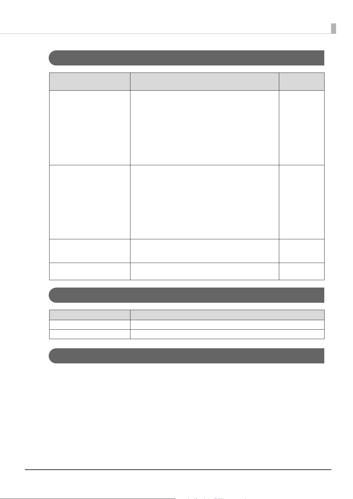
Describes features of the product.
Describes basic procedure for handling the product.
Provides information for controlling the product and for developing
application software.
Describes product specications and character code tables.
Describes how to install the product in portrait orientation and
how to install with an optional or commercially-available product.
Product Overview
Handling
Installing the Product in Various Ways
Application Development Information
Appendix
M00134202
Rev. C
Page 2

Cautions
• No part of this publication may be reproduced, stored in a retrieval system, or transmitted in any form or by
any means, electronic, mechanical, photocopying, recording, or otherwise, without the prior written
permission of Seiko Epson Corporation.
• The contents of this manual are subject to change without notice. Please contact us for the latest information.
• While every precaution has been taken in the preparation of this manual, Seiko Epson Corporation assumes
no responsibility for errors or omissions.
• Neither is any liability assumed for damages resulting from the use of the information contained herein.
• Neither Seiko Epson Corporation nor its affiliates shall be liable to the purchaser of this product or third
parties for damages, losses, costs, or expenses incurred by purchaser or third parties as a result of: accident,
misuse, or abuse of this product or unauthorized modifications, repairs, or alterations to this product, or
failure to strictly comply with Seiko Epson Corporation’s operating and maintenance instructions.
• Seiko Epson Corporation shall not be liable against any damages or problems arising from the use of any
options or any consumable products other than those designated as Original Epson Products or Epson
Approved Products by Seiko Epson Corporation.
Trademarks
EPSON, EXCEED YOUR VISION, and ESC/POS are registered trademarks of Seiko Epson Corporation.
Microsoft and Windows are registered trademarks of Microsoft Corporation in the United States and other
countries.
IOS is a trademark or registered trademark of Cisco in the U.S. and other countries and is used under license.
Apple, Apple TV, Apple Watch, iPad, iPad Air, iPad Pro, iPhone, and Lightning are trademarks of Apple Inc.,
registered in the U.S. and other countries. tvOS is a trademark of Apple Inc. The trademark "iPhone" is used in
Japan with a license from Aiphone K.K.
Android™ is a trademark of Google LLC.
Google Play and Google Play logo are trademarks of Google LLC.
All other trademarks are the property of their respective owners and used for identification purpose only.
ESC/POS® Command System
Epson ESC/POS is a proprietary POS printer command system that includes patented or patent-pending
commands. ESC/POS is compatible with most Epson POS printers and displays. ESC/POS is designed to reduce
the processing load on the host computer in POS environments. It comprises a set of highly functional and
efficient commands and also offers the flexibility to easily make future upgrades.
©Seiko Epson Corporation 2020-2021.
Page 3

For Safety
Key to Symbols
The symbols in this manual are identified by their level of importance, as defined below. Read the following
carefully before handling the product.
You must follow warnings carefully to avoid serious bodily injury.
WARNING
You must follow cautions carefully to avoid the following risks.
• Risk of physical injuries
CAUTION
• Risk of property damage
• Risk of information loss
Provides information that must be observed to avoid damage to your equipment or a malfunction.
Provides important information and useful tips.
Warnings
WARNING
Cautions
O Immediately unplug the product when any one of the following problems occurs, and
then contact qualified service personnel. Continued use may lead to fire or electric shock.
∗ If the product emits smoke, a strange odor, or unusual noise.
∗ If water or other liquid spills into the product.
∗ If the product is too hot to touch or the case is deformed.
O Follow the guidelines below to avoid accidents such as fire, electric shock, or burn.
∗ Do not use aerosol sprayers containing flammable gas inside or around the product.
∗ Do not cover the product with cloth, or place the product in locations subject to high levels of
humidity or dust.
∗ Do not allow foreign objects or flammable objects to fall into the product.
∗ Do not touch the inside of the product except where mentioned in the manual.
∗ Do not use the product with any power supply or voltage other than the ones specified.
∗ Do not connect cables in ways other than those mentioned in the manual.
∗ Never disassemble or modify the product.
∗ Do not use a cable covered with dust or foreign matters.
∗ Do not use a damaged cable.
∗ Never insert or disconnect cables with wet hands.
CAUTION
O Follow the guidelines below to avoid bodily injury and malfunction.
∗ Set up the product on a firm, stable, horizontal surface.
∗ Do not place heavy objects on top of the product. Never stand or lean on the product.
∗ Never attempt to repair the product yourself.
O To ensure safety, unplug this product before leaving it unused for an extended period.
When transporting the product, make sure to disconnect all cables in advance.
3
Page 4

Restriction of Use
When this product is used for applications requiring high reliability/safety, such as transportation devices
related to aviation, rail, marine, automotive, etc.; disaster prevention devices; various safety devices, etc.; or
functional/precision devices, etc.; you should use this product only after giving consideration to including failsafes and redundancies into your design to maintain safety and total system reliability.
Because this product was not intended for use in applications requiring extremely high reliability/safety, such as
aerospace equipment, main communication equipment, nuclear power control equipment, or medical equipment related to direct medical care, etc., please make your own judgment on this product’s suitability after a full
evaluation.
4
Page 5

About this Manual
Aim of the Manual
This manual provides information for development engineers, which are necessary for developing, designing,
and installing POS systems.
Manual Contents
The manual is made up of the following sections:
Chapter 1 Product Overview
Chapter 2 Handling
Chapter 3 Installing the Product in Various Ways
Chapter 4 Application Development Information
Chapter 5 Appendix
5
Page 6

Contents
■ For Safety..................................................................................................................................3
Key to Symbols.................................................................................................................................................................. 3
Warnings ............................................................................................................................................................................. 3
Cautions............................................................................................................................................................................... 3
■ Restriction of Use ....................................................................................................................4
■ About this Manual ..................................................................................................................5
Aim of the Manual ........................................................................................................................................................... 5
Manual Contents .............................................................................................................................................................. 5
■ Contents....................................................................................................................................6
Product Overview ............................................................................................ 8
■ Features ....................................................................................................................................8
■ Product Configurations .........................................................................................................9
Included items...................................................................................................................................................................9
Optional Kits ...................................................................................................................................................................... 9
■ Part Names ............................................................................................................................ 10
Handling ......................................................................................................... 11
■ Connecting to the Printer................................................................................................... 11
When Connecting to TM-m30II.................................................................................................................................12
When Connecting to TM-T88VII...............................................................................................................................13
■ Connecting to the Computer............................................................................................. 14
■ Routing the USB Cable........................................................................................................ 14
■ Changing the Angle of the Display Unit.......................................................................... 15
■ Turning the Power On/Off .................................................................................................. 15
■ Adjusting the Display Brightness...................................................................................... 16
■ Cleaning the Outer Case ..................................................................................................... 17
■ Troubleshooting................................................................................................................... 18
Nothing is Displayed on the Screen ........................................................................................................................18
The Screen Looks Dark when the Display is Attached in Portrait Orientation.........................................18
Installing the Product in Various Ways........................................................ 20
■ Changing the Display Orientation to Portrait ................................................................ 20
■ Attaching the Display to a VESA Mount........................................................................... 23
■ Attaching the Display to the Optional Kit ....................................................................... 25
6
Page 7

Attaching the EXTENSION POLE UNIT FOR DM-D70 (DP-70) .........................................................................25
Attaching the CRANK POLE UNIT FOR TM-T88VI-DT2 (DP-71).......................................................................30
Application Development Information....................................................... 35
■ Controlling the Customer Display .................................................................................... 35
ePOS-Print XML...............................................................................................................................................................35
ePOS-Device XML...........................................................................................................................................................35
ESC/POS.............................................................................................................................................................................36
■ Software................................................................................................................................. 37
Development Kit ............................................................................................................................................................37
Drivers ................................................................................................................................................................................37
Utilities ...............................................................................................................................................................................38
Others.................................................................................................................................................................................38
Download .........................................................................................................................................................................38
■ Screen Display ...................................................................................................................... 39
Display Mode...................................................................................................................................................................39
Standard Mode ...............................................................................................................................................................39
Fixed Column and Row Mode ...................................................................................................................................42
Displaying Character String .......................................................................................................................................43
Displaying QR Code.......................................................................................................................................................43
Displaying Graphics Data ............................................................................................................................................44
Storing Graphics Data ..................................................................................................................................................44
Available Functions by Display Mode.....................................................................................................................45
List of Settings.................................................................................................................................................................46
Appendix......................................................................................................... 47
■ Configurable Number of Columns and Rows ................................................................. 47
When Installed in Landscape Orientation.............................................................................................................47
When Installed in Portrait Orientation ...................................................................................................................49
■ Supported Printers ..............................................................................................................51
■ Product Specifications ........................................................................................................ 53
Environmental Specification ......................................................................................................................................55
External Dimensions .....................................................................................................................................................56
■ Character Code Tables......................................................................................................... 59
■ Open Source Software Licenses ........................................................................................ 60
7
Page 8

Chapter 1 Product Overview
Product Overview
This chapter describes features of the product.
Features
This product is a customer display that can display both text and images. The main features of this product are
as follows.
Compact and Offers Installation in Various Ways
• A large screen, 7 inch (800 x 480 pixels), on a compact body
• Both landscape and portrait orientations are available
• The product is USB bus powered.
• Complies with VESA standard (75 x 75mm). A commercially available VESA mount such as a wall bracket or
arm stand can be attached.
• To meet various requirements, EXTENSION POLE UNIT FOR DM-D70 and CRANK POLE UNIT FOR
TM-T88VI-DT2 are available as an option.
Display
• Easy-to-see large screen
• Images can be displayed in addition to text
• QR code can be displayed
• Text in multiple lines can be displayed
• Can display in 16.2 million colors
8
Page 9

Chapter 1 Product Overview
Product Configurations
Included items
The following items are included with the product. If any item is damaged or missing, contact qualified service
personnel.
• Customer display
• Ferrite core
(Use this when connecting the product to TM-m30II/TM-T88VII)
• Manuals
Optional Kits
Model number Description
DP-70 EXTENSION POLE UNIT FOR DM-D70
Extension pole (about 24 cm tall), USB extension cable (about 1.0 m length), Stickers for
fixing the product (4 pieces)
DP-71 CRANK POLE UNIT FOR TM-T88VI-DT2
Crank pole, Screws (3 pieces)
OT-UL30 USB extension cable (about 1.0 m length)
9
Page 10

Part Names
Chapter 1 Product Overview
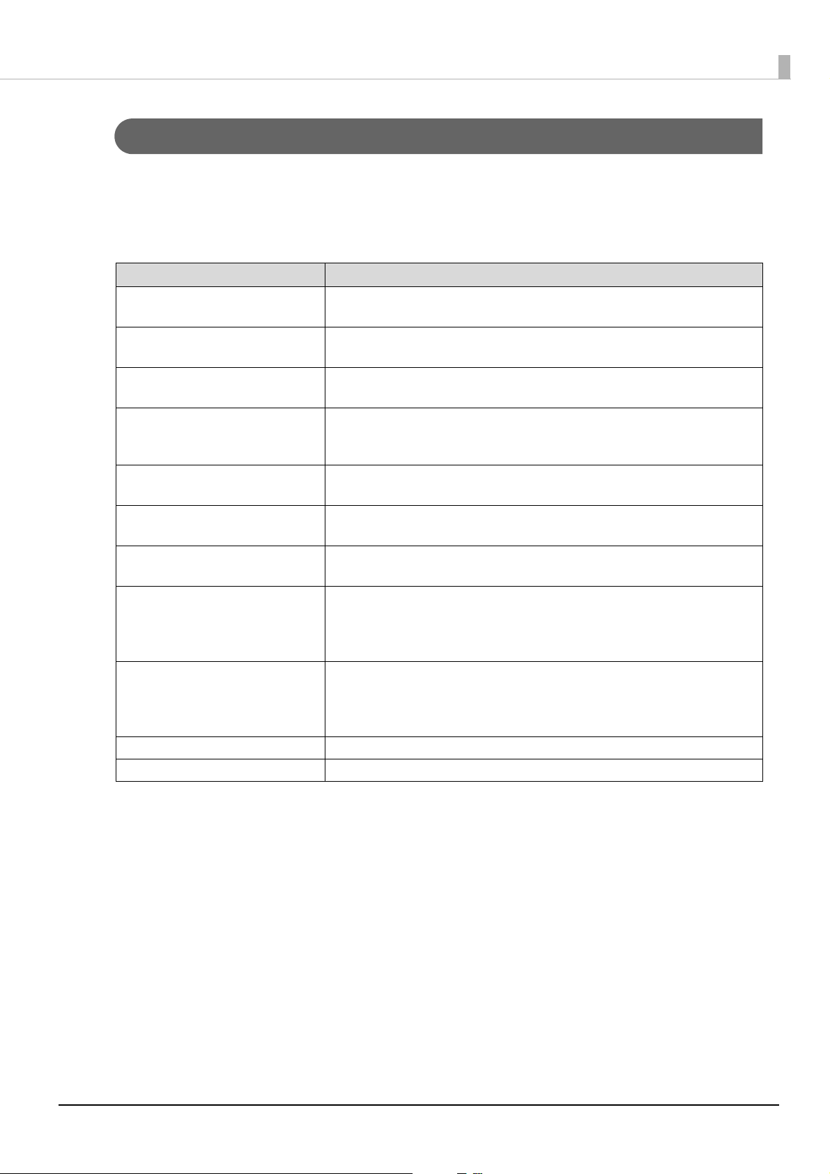
No. Part name Description
1 Display A LCD screen. The display can be tilted forward or back, and to the left or right.
2 Stand Supports the display unit.
3 USB cable Use to connect to the printer or a computer.
4 Rear cover Remove this cover when operating the brightness up/down buttons or when changing
the display orientation from landscape to portrait.
5 Screws (4 pieces) Remove the screws when changing the display orientation from landscape to portrait,
or when connecting the display to a VESA mount. The screws can be turned by hand.
6 Brightness up/down
buttons
Allows you to adjust the brightness of the display.
10
Page 11

Handling
This chapter describes basic procedures for handling the product.
Connecting to the Printer
Connect the USB cable of the customer display to the USB connector on the printer.
Chapter 2 Handling
Supported printers are listed below. See the following link for more details.
U"Supported Printers" on page 51
TM
-m30
TM-m30II
TM-m30II-H
TM-m30II-NT
TM-m30II-S
TM-m30II-SL
TM-m50
TM-T88VI
TM-T88VII
TM-T88VI-iHUB
TM-T88VI-DT2
TM-T70II-DT2
• Make sure to turn the printer off and then connect this product.
• The product cannot be connected to the USB-A Device Charging (iPad2.1A) connector that is
mounted on TM-m30II-H or other printers.
• If you want to extend the USB cable, use the optional USB extension cable (OT-UL30).
• The optional kit, EXTENSION POLE UNIT FOR DM-D70 (DP-70), includes a USB extension cable.
• You can mount this product to TM-m30II-S as a rear display. Refer to TM-m30II-S User’s Manual
for more details.
U www.epson-biz.com/?prd=tm-m30ii-s&inf=users_manual
11
Page 12

Chapter 2 Handling
When Connecting to TM-m30II
When connecting the product to TM-m30II, attach the included ferrite core to the DC cable of TM-m30II.
Bring the ferrite core close to the body of TM-m30II as much as possible.
Turn off the TM-m30II printer, and disconnect the AC cable of the AC adapter from
1
the power outlet.
Put the DC cable of TM-m30II into the ferrite core.
2
Wrap the cable around the ferrite core once.
3
Close the ferrite core until it clicks.
4
Connect the AC cable to a power outlet.
5
12
Page 13

Chapter 2 Handling
When Connecting to TM-T88VII
When connecting the product to TM-T88VII, attach the included ferrite core to the USB cable of the product.
Bring the ferrite core as close as possible to TM-T88VII.
Put the USB cable of the product into the ferrite core.
1
Wrap the cable around the ferrite core once.
2
Close the ferrite core until it clicks.
3
13
Page 14

Connecting to the Computer
Connect the USB cable of the customer display to the USB connector on the computer.
Chapter 2 Handling
• If you want to extend the USB cable, use the optional USB extension cable (OT-UL30).
• The optional kit, EXTENSION POLE UNIT FOR DM-D70 (DP-70), includes a USB extension cable.
Routing the USB Cable
The USB cable can be routed to one of the three directions. Put the USB cable into the groove on the bottom of
the stand to secure it.
14
Page 15

Chapter 2 Handling
40°
45° 45°
Changing the Angle of the Display Unit
You can adjust the angle of the display by tilting it forward or back, and to the left or right. Hold the stand with
your hand and move the display unit.
It can be tilted up to 40 degrees forward or back and up to 45 degrees to the left or right.
Do not attempt to move the display to an angle outside the allowable range. Doing so may cause
the display to malfunction.
Turning the Power On/Off
Since this product is bus powered, there is no power switch. The product takes its power from the printer or the
computer through the USB cable.
• When the product is powered, an EPSON logo is displayed.
• Even when the power LED of the printer is off, the display may stay on if it is still powered
through the USB connector.
15
Page 16

Adjusting the Display Brightness
The brightness of the display can be adjusted by pressing the brightness up/down buttons.
It is set to the brightest setting by default.
Turn on the display by connecting it to the printer or a computer.
1
Remove the rear cover.
2
Chapter 2 Handling
Press the brightness up/down buttons to adjust the brightness. There are four
3
brightness levels.
Attach the rear cover.
4
16
Page 17

Chapter 2 Handling
Cleaning the Outer Case
Be sure to disconnect the USB cable of the customer display from the printer or a computer, and then wipe the
customer display with a dry cloth or a cloth dampened with a little water.
• Never clean the product with alcohol, benzine, thinner, or other such solvents. Doing so may
damage or break the parts made of plastic and rubber.
CAUTION
• Rubbing the LCD screen with too much force using a dry cloth may scratch the surface.
17
Page 18

Chapter 2 Handling
Troubleshooting
Nothing is Displayed on the Screen
• Check that the USB cable is properly connected to the printer or to the computer.
U"Connecting to the Printer" on page 11
U"Connecting to the Computer" on page 14
• Adjust the brightness of the LCD screen by pressing the brightness up/down buttons.
U"Adjusting the Display Brightness" on page 16
The Screen Looks Dark when the Display is Attached in Portrait Orientation
When the display is attached in portrait orientation, the screen may look dark when viewed from the right or
the left, and may look differently when viewed from the opposite side. This is caused by gray scale inversion
phenomenon. If that happens, adjust the angle of the display.
However, if you cannot adjust the angle, for example, when you have fixed the display to a VESA mount, follow
the procedure below to make the screen appear brighter.
Remove the display and reattach it to the mount upside down.
1
Check that the screen is bright enough when viewed from an angle actually used.
2
At this step, the screen displays upside down.
Download one of the following utilities from the website.
3
For customers in North America U www.epson.com/support/
For customers in other countries U www.epson-biz.com/
• DM-D70 Utility (For Windows)
• TM Utility (For Android/iOS)
18
Page 19

Chapter 2 Handling
Start the utility and change [Display Settings] - [Display direction] to [Upside
4
down] to flip the screen vertically.
19
Page 20
Chapter 3 Installing the Product in Various Ways
Installing the Product in Various Ways
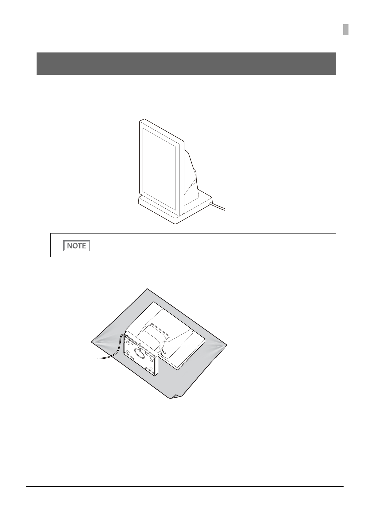
Changing the Display Orientation to Portrait
Follow the procedure below to change the display orientation to portrait.
Change the display orientation to portrait if your application software supports portrait display.
Place the product screen-side down on a soft cloth or the like.
1
20
Page 21

Chapter 3 Installing the Product in Various Ways
Remove the rear cover.
2
Remove the four screws.
3
Release the USB cable from the notch, and then remove the stand.
4
21
Page 22
Chapter 3 Installing the Product in Various Ways
Change orientation of the stand referring to the mark on the rear of the display.
5
Secure the stand with the four screws.
6
Route the USB cable as shown below.
7
Attach the rear cover.
8
22
Page 23
Chapter 3 Installing the Product in Various Ways
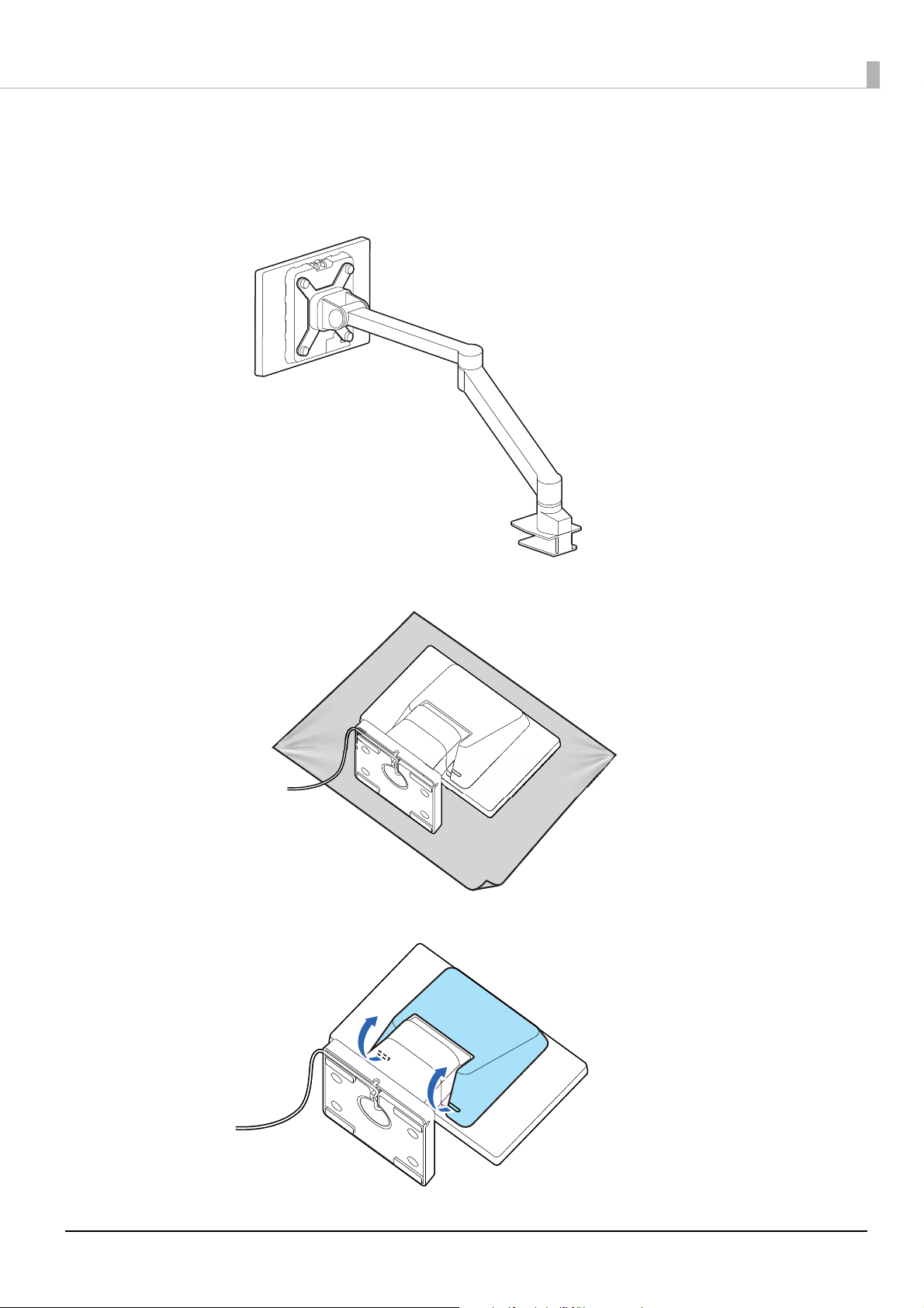
Attaching the Display to a VESA Mount
Follow the procedure below to attach the display to a mount such as a wall bracket or arm stand that complies
with VESA standard (75 x 75 mm).
Place the product screen-side down on a soft cloth or the like.
1
Remove the rear cover.
2
23
Page 24
Chapter 3 Installing the Product in Various Ways
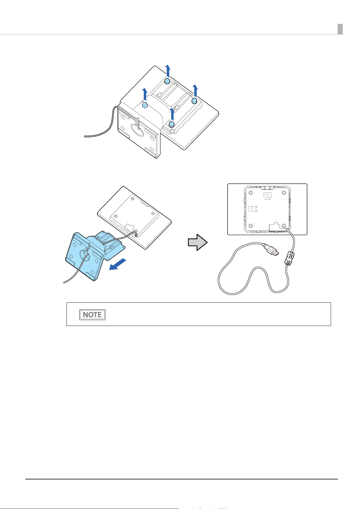
Remove the four screws.
3
Remove the stand and then pull out the USB cable from the stand.
4
Check the marks on the rear of the display to know which side is top or bottom.
Attach the display to a VESA mount such as a wall bracket or arm stand.
5
Follow the instruction manual for the VESA mount to attach the mount.
24
Page 25
Chapter 3 Installing the Product in Various Ways
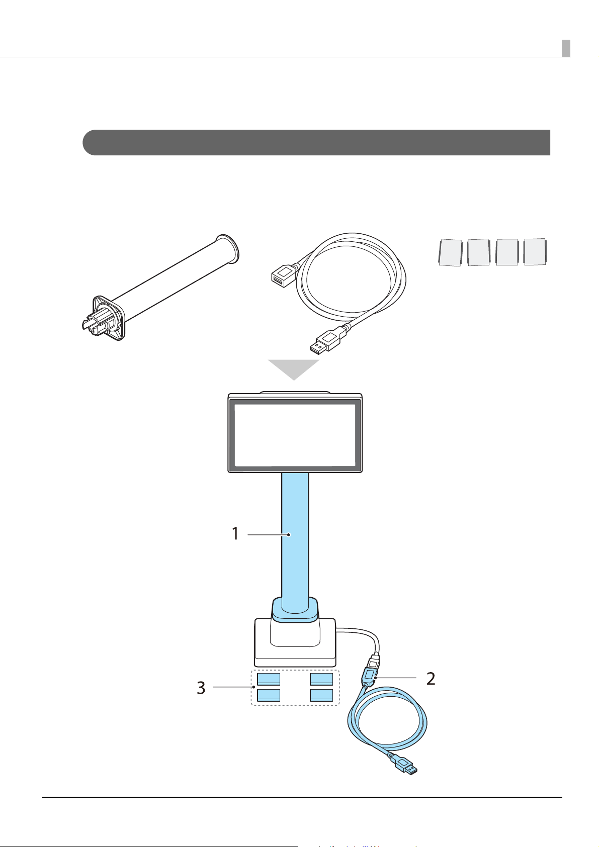
2. USB extension cable 3. Stickers for fixing
the product
1. Extension pole
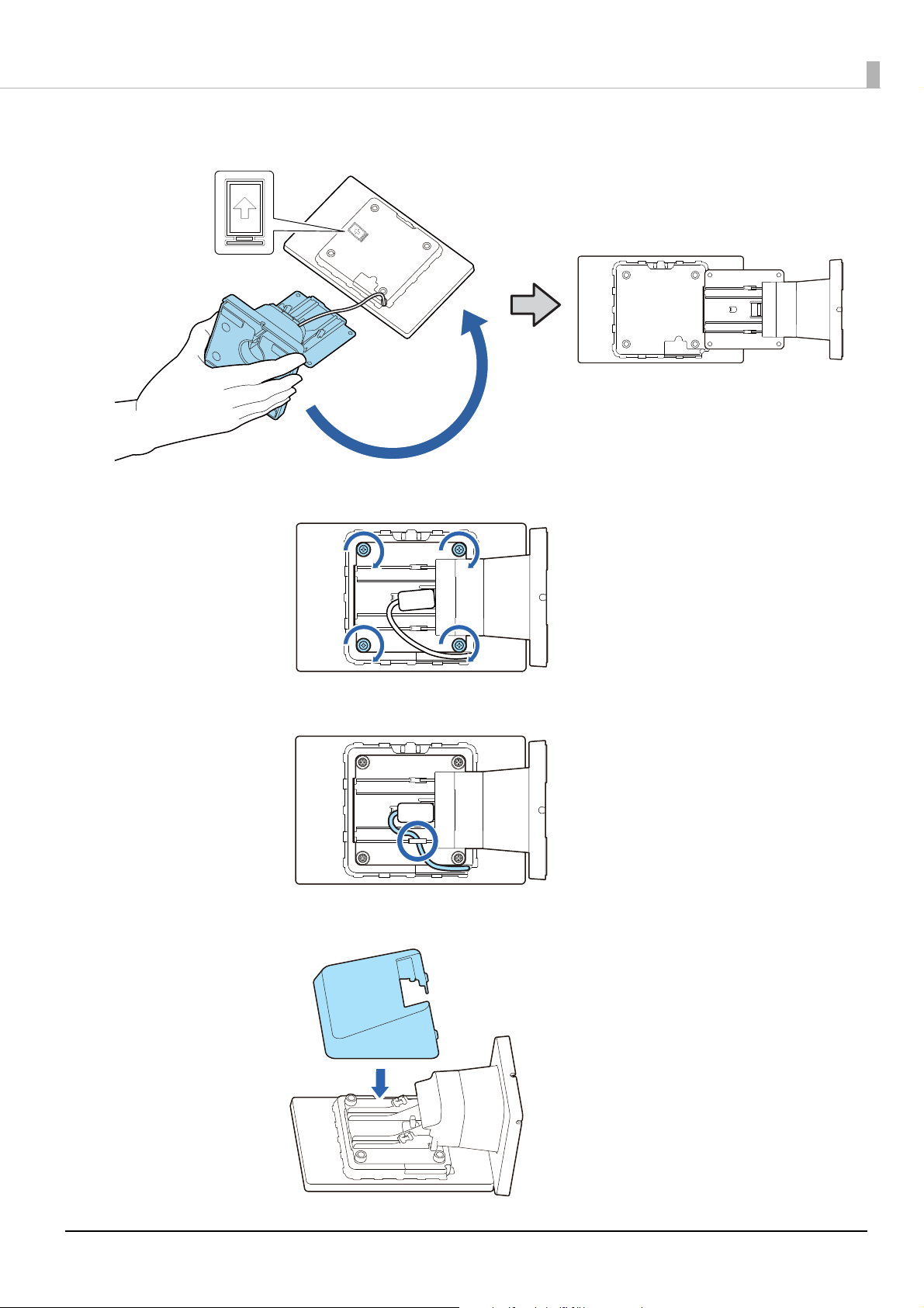
Attaching the Display to the Optional Kit
Attaching the EXTENSION POLE UNIT FOR DM-D70 (DP-70)
Follow the procedure below to attach the optional kit, EXTENSION POLE UNIT FOR DM-D70 (DP-70).
Contents of the DP-70 package
25
Page 26

Chapter 3 Installing the Product in Various Ways
Place the product screen-side down on a soft cloth or the like.
1
Raise the stand.
2
Push the tabs inward and pull out the stand.
3
26
Page 27

Chapter 3 Installing the Product in Various Ways
Pass the USB cable through the extension pole.
4
Attach the extension pole to the display. Insert the tab on the pole into the groove
5
on the display.
Pass the USB cable through the stand.
6
27
Page 28

Chapter 3 Installing the Product in Various Ways
Attach the stand to the extension pole. Insert the tab on the stand into the groove
7
on the pole.
Secure the USB cable by fitting it into the groove, and then route the cable so that
8
it passes through one of the three notches.
Make sure to fit the cable into the groove to secure the cable properly.
Connect the USB extension cable if necessary.
9
28
Page 29

Chapter 3 Installing the Product in Various Ways
Attach the four stickers to the bottom of the stand.
10
To prevent the product from falling over, use the stickers to secure the product to a
table, desk, or etc.
To remove the extension pole from the display, pull the pole hard.
29
Page 30

Chapter 3 Installing the Product in Various Ways
1. Crank pole 2. Three screws
Attaching the CRANK POLE UNIT FOR TM-T88VI-DT2 (DP-71)
Follow the procedure below to attach the optional kit, CRANK POLE UNIT FOR TM-T88VI-DT2 (DP-71).
Contents of the DP-71 package
Remove the connector cover of the TM-T88VI-DT2.
1
Push both lower sides of the cover inward to disengage the hooks, and remove the cover.
30
Page 31

Chapter 3 Installing the Product in Various Ways
Remove the U-shape part from the connector cover.
2
Place the product screen-side down on a soft cloth or the like.
3
Raise the stand.
4
31
Page 32

Chapter 3 Installing the Product in Various Ways
Push the tabs inward and pull out the stand.
5
Pass the USB cable through the crank pole.
6
32
Page 33

Chapter 3 Installing the Product in Various Ways
Attach the crank pole to the display as shown below.
7
Secure the USB cable to the crank pole.
8
Lay TM-T88VI-DT2 on its side.
9
Pass the USB cable through the TM-T88VI-DT2.
10
33
Page 34
Chapter 3 Installing the Product in Various Ways
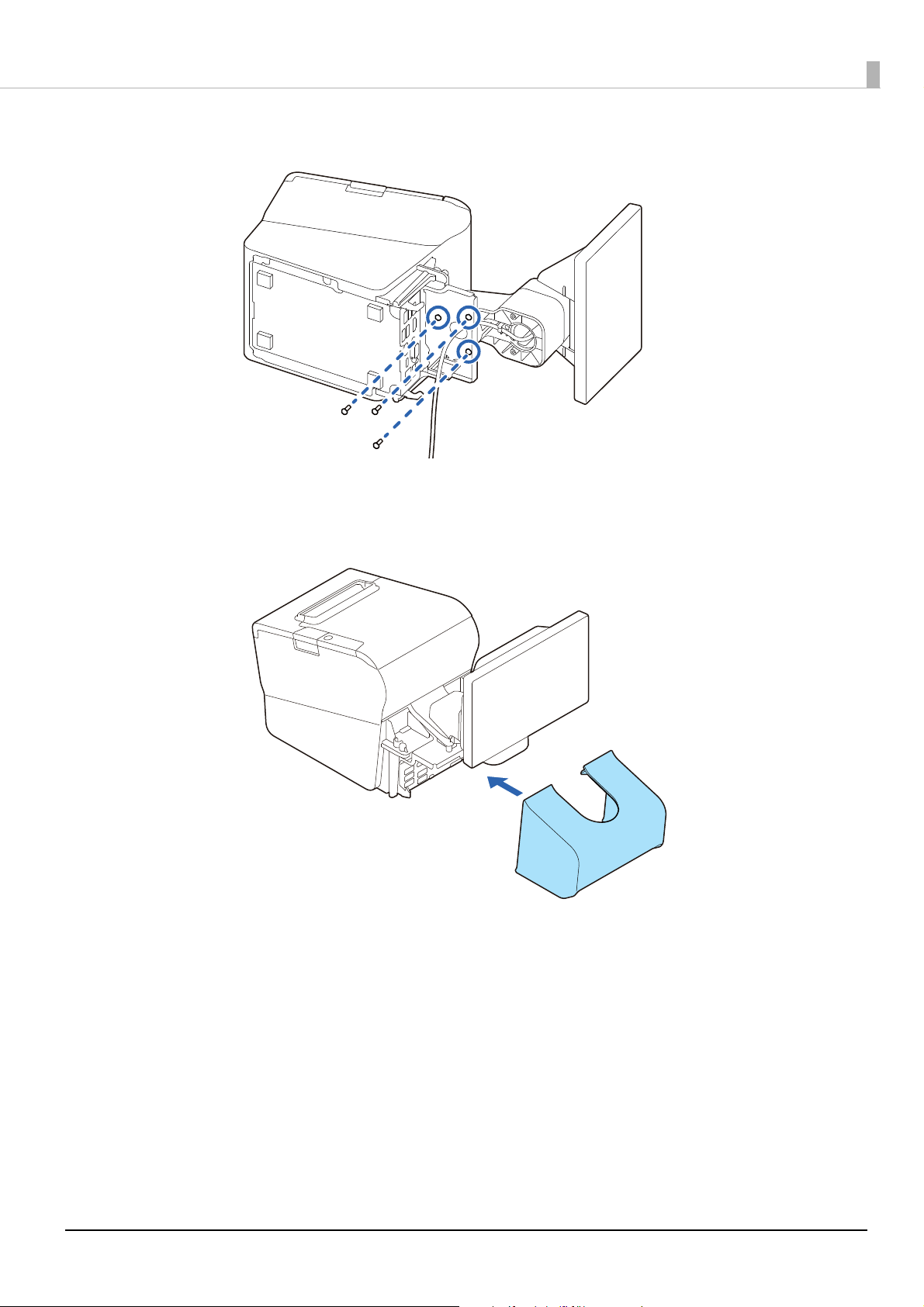
Secure the display and crank pole with the three screws.
11
Connect the USB cable to the connector on the TM-T88VI-DT2.
12
Attach the connector cover.
13
34
Page 35
Chapter 4 Application Development Information
Application Development Information
This chapter explains how to control the product as well as necessary information for developing system
applications using the product.
Controlling the Customer Display
This product supports the following control commands.
• ePOS-Print XML
• ePOS-Device XML
• ESC/POS
ePOS-Print XML and ePOS-Device XML can be used only when the product is directly connected to
a supported TM printer. See the link below for information on the supported printers.
U "Supported Printers" on page 51
To control the product from an application, use the above commands or the following development kits and
drivers.
• Epson ePOS SDK
• EPSON OPOS ADK
• EPSON OPOS ADK for .NET
• EPSON Advanced Printer Driver
ePOS-Print XML
ePOS-Print XML is the Epson original control command system for POS printers and customer displays. This
allows an application on a computer or tablet to send an XML-format request to a TM printer that supports the
XML over an HTTP connection. ePOS-Print Service that is pre-installed on the XML-compatible printer
receives the request and printing or displaying data is performed according to the request. For more details
about ePOS-Print XML, see the ePOS-Print XML User's Manual.
ePOS-Device XML
ePOS-Device XML is the Epson original control command system defined using xml for POS printers and
peripheral devices. This allows an application on a computer or tablet to send an XML-format request to a TM
Intelligent printer over a socket connection. ePOS-Device Service that is pre-installed on the TM Intelligent
printer receives the request and printing or displaying data is performed according to the request. For more
details about ePOS-Device XML, see the ePOS-Device XML User's Manual.
35
Page 36

Chapter 4 Application Development Information
ESC/POS
ESC/POS is the Epson original printer command system for POS printers and customer display. With ESC/POS
commands, you can directly control all the product functions, but comparing to using drivers and the
development kit, more detailed information about the product specifications and combination of commands
are required.
For details on the ESC/POS commands, see "ESC/POS Command Reference for Customer Displays" by
accessing the URL below.
U www.epson-biz.com/pos/reference/
36
Page 37
Chapter 4 Application Development Information
Software
The following pieces of software are provided for application development.
Development Kit
Software Description
Epson ePOS SDK Allows you to develop application software with low quantity of codes using
for Android
for iOS
for JavaScript
EPSON OPOS ADK OCX driver that controls the POS peripheral devices using the OLE technologies
EPSON OPOS ADK for .NET The OPOS ADK for .NET is a POS industry standard printer driver compatible with
∗: OLE technology developed by Microsoft divides software into part blocks. The OPOS driver is completely
different from a printer driver for Windows. You need to program it in a development environment such as Visual
Basic. It is not a driver that enables printing from a commercially available application.
You can acquire documents regarding the UnifiedPOS from the following link.
https://www.omg.org/retail/unified-pos.htm
extensive APIs. You can easily develop an iOS/Android native application or Web
application.
Because controlling POS peripherals with original commands is not required on the
application side, efficient system development is possible.
Microsoft POS for .NET.
It allows you to develop applications that are compatible with the UPOS (Unified POS)
specifications.
When developing applications, use a separate development environment such as
Microsoft Visual Studio .NET.
*
.
Drivers
Software Description
EPSON Advanced Printer Driver
(APD)
TM Virtual Port Driver Use this when controlling the display using ESC/POS
Windows printer driver that can send data to be displayed on
the customer display. It is not possible to get status of the
customer display.
commands. The customer display connected to a USB port is
recognized as a virtual serial port.
Operating
environment
Windows
Windows
37
Page 38
Utilities
Chapter 4 Application Development Information
Software Description
DM-D70 Utility A utility for checking and changing various settings of the
product. Use this utility to:
• Configure the screen layout settings
• Store data for slide show
• Store frame data
• Run an operation check
• Store image data
• Change display settings
• Save or restore the settings
Epson TM Utility A utility that is available on the App Store or Google Play. You can
change settings of the product from an iOS or Android device.
Use this utility to:
• Configure the screen layout settings
• Store data for slide show
• Store frame data
• Run an operation check
• Store image data
• Change display settings
Deployment Tool This allows you to make the settings of the product, the printer
and the network simultaneously. Settings of multiple products
can be done efficiently.
DM-D70 Firmware Updater Use this to update the firmware of the product.
An executable file and the firmware are packaged together.
Operating
environment
Windows
Android, iOS
Windows
Windows
Others
Manual Description
ePOS-Print XML User's Manual Describes ePOS-Print XML statements. This manual comes with sample programs.
ePOS-Device XML User's Manual Describes ePOS-Device XML statements. This manual comes with sample programs.
Download
You can obtain software and manuals from one of the following URLs.
For customers in North America, go to the following web site:
U www.epson.com/support/
For customers in other countries, go to the following web site:
U www.epson-biz.com/
38
Page 39

Chapter 4 Application Development Information
Image area Text area
Screen Display
This product is capable of displaying characters and backgrounds in color, and graphics data. This section
describes the functions and capability of the display.
For information necessary for developing application software, see the manual for the development kit and
driver, and the ESC/POS Command Reference.
Display Mode
The product has the two display modes.
Display Mode Description
Standard mode All functions of the product can be used in this mode.
Fixed column and row mode This mode allows you to fix the number of columns and rows to the same as those of
DM-D30, DM-D110, DM-D210, or DM-D500.
Both modes have two areas; text area and image area. The text area mainly displays character string, and the
mage area displays graphics data.
i
Standard Mode
Contents that can be displayed in the text and image areas in the standard mode are as follows.
Display Area Description
Text area Character string, QR code, Frame image (PNG)
Image area Image data (JPEG, PNG), Slide show images (JPEG, PNG)
It is not possible to get information about the display orientation (landscape or portrait) from
application software or any other tool.
39
Page 40
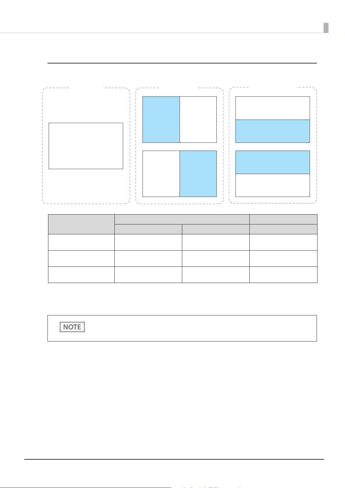
The following screen layouts are available in the standard mode.
When Installed in Landscape Orientation
Chapter 4 Application Development Information
[Full screen]
Text area
and
Image area
Screen Layout
Full screen
Vertical split
(divided into right and left)
Horizontal split
(divided into up and down)
[Vertical split]
Image area Text area
Text area Image area
[Horizontal split]
Text area
Image area
Image area
Text area
Text area Image area
Columns x Rows* Width x Height (pixels) Width x Height (pixels)
33 x 10
(44 x 13)
16 x 9
(22 x 13)
33 x 5
(44 x 6)
800 x 480 800 x 480
400 x 480 400 x 480
800 x 240 800 x 240
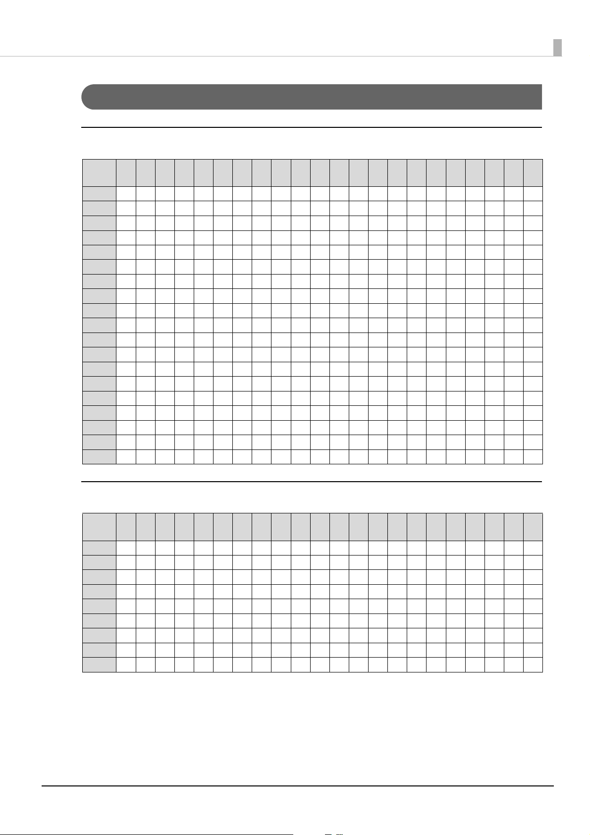
∗: The number of columns and rows of the text area are default values. The values in parentheses are maximum
values. You can change the values from your application software. See the link below for information about the
number of columns and rows that can be set.
U "Configurable Number of Columns and Rows" on page 47
• In the full screen, the text area and the image area are laying on top of each other. Display each
area with attention to the overlapping area.
• You can change the screen layout setting from your application software.
40
Page 41

When Installed in Portrait Orientation
Text area
and
Image area
[Full screen]
Image area
Text area
[Horizontal split]
Image area
Text area
Image area
Text area
[Horizontal split 1:2]
Image area
Text areaImage area
Text area
[Horizontal split 2:1]
Image area
Text area
Chapter 4 Application Development Information
Full screen
Horizontal split
(divided into up and down)
Horizontal split 2:1
Horizontal split 1:2
∗: The number of columns and rows of the text area are default values. The values in parentheses are maximum
values. You can change the values from your application software. See the link below for information about the
number of columns and rows that can be set.
U "Configurable Number of Columns and Rows" on page 47
Screen Layout
Text area Image area
Tex t are a: 1
Image area: 2
Tex t are a: 2
Image area: 1
Columns x Rows*
20 x 16
(22 x 19)
20 x 8
(22 x 9)
20 x 5
(22 x 6)
20 x 11
(22 x 12)
Width x Height
(pixels)
480 x 800 480 x 800
480 x 400 480 x 400
480 x 267 480 x 533
480 x 533 480 x 267
Width x Height
(pixels)
• In the full screen, the text area and the image area are laying on top of each other. Display each
area with attention to the overlapping area.
• You can change the screen layout setting from your application software.
41
Page 42

Chapter 4 Application Development Information
[Horizontal split]
[Display in center]
Text area
Text area
Text area
Image area
Image area
Fixed Column and Row Mode
This mode is for users who use existing application software developed for an earlier customer display.
Modifying the software to use with this product can be done with less work. The number of columns and rows
of the text area are the same as those of DM-D30, DM-D110, DM-D210, or DM-D500. To use this mode, the
display needs to be installed in landscape orientation
When using this mode, use DM-D70 Utility to configure color of characters at power-on, background color,
slide show, and frame. The settings cannot be changed while running your application software.
Contents that can be displayed in the text and image areas in the fixed column and row mode are as follows.
Display Area Description
Text area Character string, Frame image (PNG)
Image area Slide show images (JPEG, PNG)
The following screen layouts are available in the fixed column and row mode.
Screen Layout
Horizontal split
(divided into up and down)
Display in center
• Even when using the fixed column and row mode, software for this product is required. Software
• To center a frame, create a graphic image of 800 x 480 pixels, and make the text area (coordinate
• The "Display in center" layout does not have an image area. Therefore, slide show cannot be
Text area Image area
Columns x Rows Width x Height (pixels) Width x Height (pixels)
20 x 2
32 x 2
32 x 3
32 x 4
42 x 8
for DM-D30, DM-D110, DM-D210, or DM-D500 cannot be used.
(0,120) to (800,360)) transmissive.
displayed.
800 x 240 800 x 240
42
Page 43

Chapter 4 Application Development Information
Displaying Character String
Character string can be displayed in the text area. You can change the color of the characters and background.
In the standard mode, the number of columns and rows in the text area can be changed from application
software.
The character size is automatically determined by the specified number of columns and rows. The character size
is uniform in the text area and it is not possible to change the character size partially.
Displaying QR Code
A QR code can be displayed in the text area in the standard mode. Note the following points for displaying a QR
code.
• Display a QR code so that it fits inside the text area.
• A displayed QR code is not square. This is caused by difference in aspect ratio of the pixels on the LCD.
• Since the recognition rate of a QR code varies depending on widths of the modules, brightness of the display,
and characteristics of the reader, make sure to check the recognition rate beforehand to determine the
settings and use conditions so that the requirements of the reader are satisfied.
• Display a QR code so that it is not overlaid on the text area.
43
Page 44
Chapter 4 Application Development Information
Tex t ar e a
Transmissive area
Frame data (PNG)
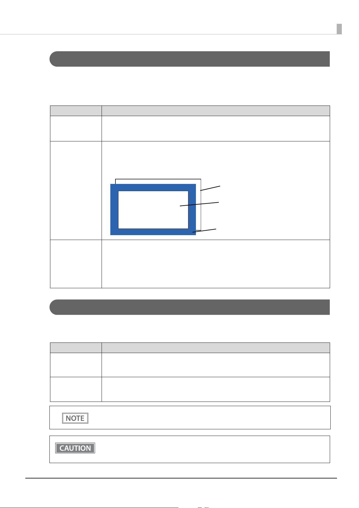
Displaying Graphics Data
Graphics data that can be displayed in the text and image areas are as follows.
For specifications of available JPEG and PNG data, see the link below.
U"Product Specifications" on page 53
Typ e of Graphi cs Description
Image data • Displayed in the image area in the standard mode.
• By specifying the display size, the image can be reduced or enlarged and displayed in the image
area.
Frame • Graphics data that can be always displayed in the text area to decorate the text area. To display
character string over the frame, the portion of the frame PNG data that overlap with characters
needs to be transmissive.
• Match the size of the frame data (horizontal and vertical pixel size) with the size of the text area.
ABCDEFGHIJ
0123456789
Slide show • Multiple graphics data can be displayed in turn at regular intervals in the image area.
• Match the size of each graphics data (horizontal and vertical pixel size) with the size of the image
area. If the size of the graphics data is larger than the image area, the graphics is reduced so that it
fits inside the image area.
• All graphics data used for the slide show need to be uniform in size. If they are different in size, an
immediately preceding image remains.
Storing Graphics Data
To display graphics data in the text or image area, store the data in the memory dedicated for graphics data.
There are two types of memory.
Memory Description
NV Graphics NV (non-volatile) memory of the product. The data in the memory is not erased even when the
power is turned off. Graphics data for slide show or frame can be stored only in the NV Graphics
memory. NV Graphics can store data up to 10 MB.
Download Graphics RAM (random access memory) of the product. The data in the memory is erased when the power is
turned off.
Download Graphics can store data up to 1.5 MB.
It is recommended to use DM-D70 Utility or TM Utility to store data in the NV memory. Graphics
data can be converted in appropriate format and then stored.
It may take about 110 seconds to store graphics data in the NV memory. This is because an
optimization of the NV memory is performed. During the optimization, a message “Optimizing” is
displayed on the screen.
44
Page 45
Chapter 4 Application Development Information
Available Functions by Display Mode
The table below shows differences in available functions between the standard mode and the fixed column and
row mode.
Standard mode Fixed column and row mode
Text area Image area Text area Image area
Changing the number of
columns and rows
Displaying character string
Changing characters color
Changing background color
(rows)
Changing background color
(full screen)
Displaying a QR code
Displaying an image
Displaying slide show
Displaying frame
✔
✔
✔
✔
✔
✔
-
-
✔
-Fixed *-
-
- ✔ *-
---
- ✔ *-
---
✔
✔
- ✔ *-
✔
--
- ✔ *
-
∗: Use DM-D70 Utility or TM Utility to change the settings. You cannot change them from your application software.
45
Page 46
Chapter 4 Application Development Information
List of Settings
There are settings you can change in addition to the screen layout setting. Use DM-D70 Utility or TM Utility to
change the settings. Or you can change them from your application software by using the development kit and
the driver. For more details, see the manual for the development kit and driver, and the ESC/POS Command
Reference.
Item Description
Screen Layout settings Allows you to change the display mode.
Default: standard mode (landscape, full screen)
Text color Allows you to change the color of characters.
Default: white
Background color Allows you to change the color of background.
Default: black
Screen timeout Allows you to change the time from when the product receives no data until the
back light turns off.
Default: Normally On
Code-page Allows you to change the code page for the product.
Default: PC437 (USA: Standard Europe)
International character set Allows you to change the international character set for the product.
Default: USA
Adjust Brightness Allows you to change the brightness of the back light.
Default: 100%
ePOS-Device XML mode Select [DM-D30] when using the product in the fixed column and row mode with
application software that uses ePOS-Device XML functions.
Default: DM-D70
U"Supported Printers" on page 51
Display direction Allows you to change the display direction setting.
Default: F
U"The Screen Looks Dark when the Display is Attached in Portrait Orientation"
on pa
Autoplay slideshow Allows you to set the slide show to run when the product starts up.
I
mage change time Allows you to change time duration to switch images in slide show.
orward direction
ge 18
46
Page 47

Appendix
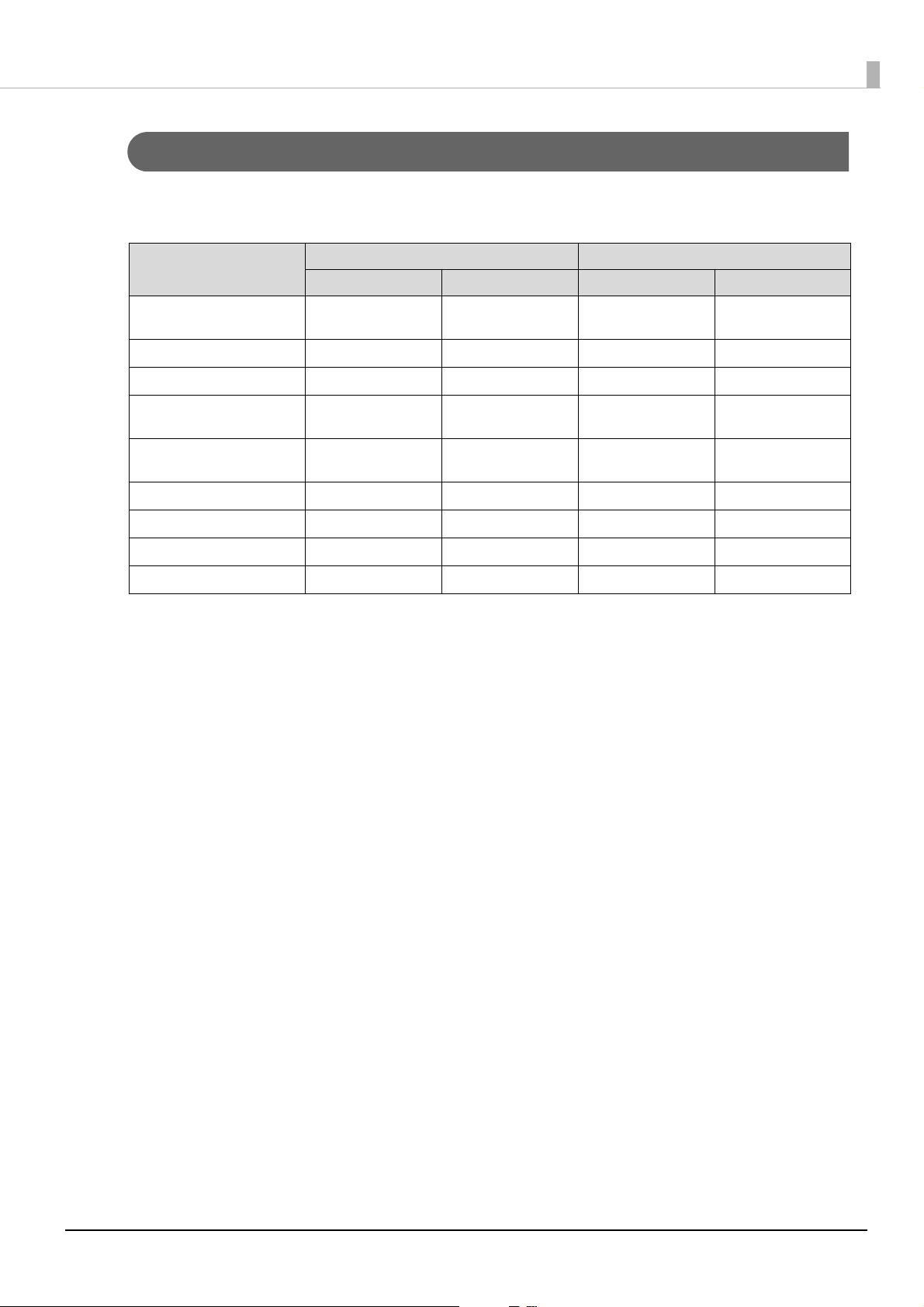
Configurable Number of Columns and Rows
When Installed in Landscape Orientation
Full screen
Appendix
Column
Row
Column
Row
1 2 3 4 5 6 7 8 9 10 11 12 13 14 15 16 17 18 19 20 21 22
1 ---
2 ------
3 ---------
4 -------------
5 ----------------
6 -------------------
7 ----------------------
8 ----------------------
9 ----------------------
10 ----------------------
11 ----------------------
12 ----------------------
13 ----------------------
23 24 25 26 27 28 29 30 31 32 33 34 35 36 37 38 39 40 41 42 43 44
1
✔✔✔✔✔✔✔✔✔✔✔✔✔✔✔✔✔✔✔✔✔✔
2
✔✔✔✔✔✔✔✔✔✔✔✔✔✔✔✔✔✔✔✔✔✔
3
✔✔✔✔✔✔✔✔✔✔✔✔✔✔✔✔✔✔✔✔✔✔
4
✔✔✔✔✔✔✔✔✔✔✔✔✔✔✔✔✔✔✔✔✔✔
5
✔✔✔✔✔✔✔✔✔✔✔✔✔✔✔✔✔✔✔✔✔✔
6
✔✔✔✔✔✔✔✔✔✔✔✔✔✔✔✔✔✔✔✔✔✔
7
✔✔✔✔✔✔✔✔✔✔✔✔✔✔✔✔✔✔✔✔✔✔
8 ---
9 -------
10 ----------
11 --------------
12 ----------------
13 --------------------
✔✔✔✔✔✔✔✔✔✔✔✔✔✔✔✔✔✔✔
✔✔✔✔✔✔✔✔✔✔✔✔✔✔✔✔
✔✔✔✔✔✔✔✔✔✔✔✔✔
✔✔✔✔✔✔✔✔✔
✔✔✔✔✔✔
✔✔✔
✔✔✔✔✔✔✔✔✔✔✔✔✔✔✔✔✔✔✔
✔✔✔✔✔✔✔✔✔✔✔✔✔✔✔
✔✔✔✔✔✔✔✔✔✔✔✔
✔✔✔✔✔✔✔✔
✔✔✔✔✔✔
✔✔
47
Page 48

Vertical split (screen divided into right and left)
Appendix
Column
Row
1 2 3 4 5 6 7 8 9 10 11 12 13 14 15 16 17 18 19 20 21 22
1-
2 ---
3 ----
4 ------
5 --------
6 ---------
7 -----------
8 ------------
9 --------------
10 ----------------
11 ------------------
12 -------------------
13 ---------------------
✔✔✔✔✔✔✔✔✔✔✔✔✔✔✔✔✔✔✔✔✔
✔✔✔✔✔✔✔✔✔✔✔✔✔✔✔✔✔✔✔
✔✔✔✔✔✔✔✔✔✔✔✔✔✔✔✔✔✔
✔✔✔✔✔✔✔✔✔✔✔✔✔✔✔✔
✔✔✔✔✔✔✔✔✔✔✔✔✔✔
✔✔✔✔✔✔✔✔✔✔✔✔✔
✔✔✔✔✔✔✔✔✔✔✔
✔✔✔✔✔✔✔✔✔✔
✔✔✔✔✔✔✔✔
✔✔✔✔✔✔
✔✔✔✔
✔✔✔
Horizontal split (screen divided into up and down)
Column
Row
1 2 3 4 5 6 7 8 9 10 11 12 13 14 15 16 17 18 19 20 21 22
1 ------
2 -------------
3 -------------------
4 ----------------------
5 ----------------------
6 ----------------------
✔✔✔✔✔✔✔✔✔✔✔✔✔✔✔✔
✔✔✔✔✔✔✔✔✔
✔✔✔
✔
Column
Row
23 24 25 26 27 28 29 30 31 32 33 34 35 36 37 38 39 40 41 42 43 44
1
✔✔✔✔✔✔✔✔✔✔✔✔✔✔✔✔✔✔✔✔✔✔
2
✔✔✔✔✔✔✔✔✔✔✔✔✔✔✔✔✔✔✔✔✔✔
3
✔✔✔✔✔✔✔✔✔✔✔✔✔✔✔✔✔✔✔✔✔✔
4 ---
5 ----------
6 ----------------
✔✔✔✔✔✔✔✔✔✔✔✔✔✔✔✔✔✔✔
✔✔✔✔✔✔✔✔✔✔✔✔
✔✔✔✔✔✔
48
Page 49
When Installed in Portrait Orientation
Full screen
Appendix
Column
Row
1 2 3 4 5 6 7 8 9 10 11 12 13 14 15 16 17 18 19 20 21 22
1-
2--
3 ---
4 ----
5 -----
6 -------
7 --------
8 ---------
9 ----------
10 -----------
11 ------------
12 --------------
13 ---------------
14 ----------------
15 -----------------
16 ------------------
17 --------------------
18 --------------------
19 ---------------------
✔✔✔✔✔✔✔✔✔✔✔✔✔✔✔✔✔✔✔✔✔
✔✔✔✔✔✔✔✔✔✔✔✔✔✔✔✔✔✔✔✔
✔✔✔✔✔✔✔✔✔✔✔✔✔✔✔✔✔✔✔
✔✔✔✔✔✔✔✔✔✔✔✔✔✔✔✔✔✔
✔✔✔✔✔✔✔✔✔✔✔✔✔✔✔✔✔
✔✔✔✔✔✔✔✔✔✔✔✔✔✔✔
✔✔✔✔✔✔✔✔✔✔✔✔✔✔
✔✔✔✔✔✔✔✔✔✔✔✔✔
✔✔✔✔✔✔✔✔✔✔✔✔
✔✔✔✔✔✔✔✔✔✔✔
✔✔✔✔✔✔✔✔✔✔
✔✔✔✔✔✔✔✔
✔✔✔✔✔✔✔
✔✔✔✔✔✔
✔✔✔✔✔
✔✔✔✔
✔✔
✔✔
✔
Horizontal split (screen divided into up and down)
Column
Row
1 2 3 4 5 6 7 8 9 10 11 12 13 14 15 16 17 18 19 20 21 22
1--
2 ----
3 -------
4 ---------
5 -----------
6 --------------
7 ----------------
8 ------------------
9 --------------------
✔✔✔✔✔✔✔✔✔✔✔✔✔✔✔✔✔✔✔✔
✔✔✔✔✔✔✔✔✔✔✔✔✔✔✔✔✔✔
✔✔✔✔✔✔✔✔✔✔✔✔✔✔✔
✔✔✔✔✔✔✔✔✔✔✔✔✔
✔✔✔✔✔✔✔✔✔✔✔
✔✔✔✔✔✔✔✔
✔✔✔✔✔✔
✔✔✔✔
✔✔
49
Page 50

Horizontal split 1:2 (screen divided into up and down at a ratio of 1:2)
Appendix
Column
Row
1 2 3 4 5 6 7 8 9 10 11 12 13 14 15 16 17 18 19 20 21 22
1 ---
2 -------
3 ----------
4 --------------
5 -----------------
6 --------------------
✔✔✔✔✔✔✔✔✔✔✔✔✔✔✔✔✔✔✔
✔✔✔✔✔✔✔✔✔✔✔✔✔✔✔
✔✔✔✔✔✔✔✔✔✔✔✔
✔✔✔✔✔✔✔✔
✔✔✔✔✔
Horizontal split 2:1 (screen divided into up and down at a ratio of 2:1)
Column
Row
1 2 3 4 5 6 7 8 9 10 11 12 13 14 15 16 17 18 19 20 21 22
1-
2 ---
3 -----
4 -------
5 --------
6 ----------
7 ------------
8 --------------
9 ----------------
10 -----------------
11 -------------------
12 --------------------
✔✔✔✔✔✔✔✔✔✔✔✔✔✔✔✔✔✔✔✔✔
✔✔✔✔✔✔✔✔✔✔✔✔✔✔✔✔✔✔✔
✔✔✔✔✔✔✔✔✔✔✔✔✔✔✔✔✔
✔✔✔✔✔✔✔✔✔✔✔✔✔✔✔
✔✔✔✔✔✔✔✔✔✔✔✔✔✔
✔✔✔✔✔✔✔✔✔✔✔✔
✔✔✔✔✔✔✔✔✔✔
✔✔✔✔✔✔✔✔
✔✔✔✔✔✔
✔✔✔✔✔
✔✔✔
✔✔
✔✔
50
Page 51
Supported Printers
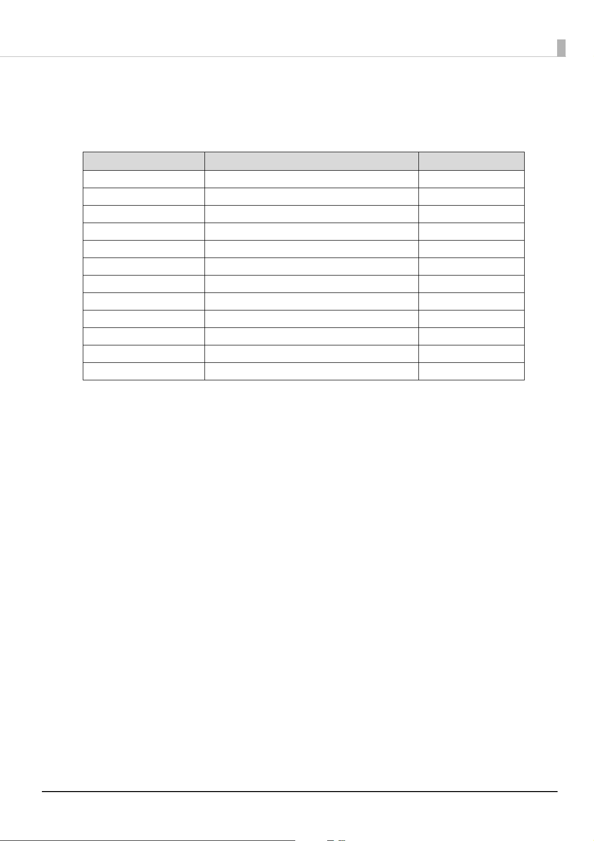
The printers that can be directly connected to the display are listed below. Available functions vary depending
on the connected printer. When the display is connected to a computer, all of the functions can be used.
Supported Printers Available Display Mode Restrictions
TM-m30 Fixed column and row mode A
TM-m30II Fixed column and row mode A
TM-m30II-H Fixed column and row mode, Standard mode B
TM-m30II-NT Fixed column and row mode, Standard mode B
TM-m30II-S Fixed column and row mode, Standard mode B
TM-m30II-SL Fixed column and row mode, Standard mode -
TM-m50 Fixed column and row mode A
TM-T88VI Fixed column and row mode A
TM-T88VII Fixed column and row mode, Standard mode C
TM-T88VI-iHUB Fixed column and row mode A
Appendix
TM-T88VI-DT2 Fixed column and row mode, Standard mode D
TM-T70II-DT2 Fixed column and row mode, Standard mode D
Restrictions A
• Cannot be used in the standard mode.
• To use application software that uses ePOS-Device XML functions, change the ePOS-Device XML mode
from [DM-D70] to [DM-D30] using DM-D70 Utility. In addition, set the screen layout setting to [Fixed
column and row mode], and then select [20 x 2] as the number of columns and rows.
• When using DM-D70 Utility/ DM-D70 Firmware Updater, connect the product to a computer directly. They
cannot be used when the product is connected to the printer.
• TM Utility cannot be used. Use DM-D70 Utility instead.
Restrictions B
• To use the product in the standard mode, the product firmware needs to be updated to Ver. 03.06A/03.06B
ESC/POS or later.
• Restrictions A apply if the firmware is not updated.
Restrictions C
• When TM-T88VII and a computer are connected via a serial or parallel port, DM-D70 cannot be used in the
Standard mode.
Restrictions D
• When developing a PC-POS application software, you cannot use EPSON Advanced Printer Driver for DMD which is pre-installed in TM-T88VI-DT2 or TM-T70II-DT2 because the software does not support DMD70. Download and use EPSON Advanced Printer Driver 6 for DM-D70.
• When developing application software that uses TM-DT software, you need to update the TM-DT software
to Ver.5.10 or later.
51
Page 52

Appendix
Available functions vary depending on which development kit and which type of driver are used.
or more details, see the manual for the development kit and driver, and the ESC/POS Command
F
Reference.
52
Page 53

Product Specifications
Display size 7 inch (800 x 480 pixels), Viewing area 154.1 x 85.9 mm
play type TFT LCD (16.2 million colors)
Dis
Pixel pitch 0.1926 (horizontal) x 0.179 (vertical) mm
The number of defective dots*
Brightness
Viewing angle (landscape orientation)*
Character classes
Character code
Numbers of characters
displayed
Image file format
Barcode 2D code (QR code)
Interface USB 2.0 High/Full speed
Power supply USB bus power (4.75 to 5.5 V DC)
Consumption current Operating: 0.5 A (max.)
VESA standard 75 x 75 mm (VESA75)
Dimensions
Mass Approx. 0.93 kg {2.05 lb}
Length of the USB cable Approx. 60 cm {23.6''}
∗1 The number of defective dots was calculated in units of sub pixel according to ISO9241-307 Class II standard.
∗2 The viewing angle is the angle where the contrast ratio exceeds 10:1. It is not the angle where gray scale inversion phenomenon
es not occur.
do
∗3 Only character types that are installed on the product can be displayed.
1
2
Alphanumeric 95 character
International characters 18 sets
Graphic characters 128 characters x 39 pages
Japanese JIS X 0213-2004 11,208 characters
Special characters
Simplified Chinese GB18030-2000
Traditional Chinese Big5 13,502 characters
Korean KS C5601
Unicode*
Landscape
(Standard mode)
Landscape
(Fixed column and row
mode)
Portrait
JPEG
PNG
Landscape 180 x 109 x 165.2 mm {7.1 x 4.3 x 6.5"} (W x D x H)
Portrait 116 x 109 x 197.2 mm {4.6 x 4.3 x 7.8"} (W x D x H)
3
5 dots or less
Approx. 300 cd/m
(Peak brightness soon after purchasing, measured at 25 degrees C)
Vertical 120°, Horizontal 150° (standard)
845 characters
UTF-8
Alphanumeric 44 columns x 13 rows (Max.)
Kanji 22 columns x 13 rows (Max.)
Alphanumeric
Kanji
Alphanumeric 22 columns x 19 rows (Max.)
Kanji 11 columns x 19 rows (Max.)
Standard Baseline JPEG
Pixel format 4:2:2 (horizontal), or 4:2:0
Size (width) Even-numbered pixels
Bit depth 8 bit
Color type True color, or true color + alpha channel
Interlace Not supported
2
(standard)
28,553 characters
8,224 characters
20 columns x 2 rows, 32 columns x 2 rows,
32 columns x 3 rows, 32 columns x 4 rows,
42 columns x 8 rows
10 columns x 2 rows, 16 columns x 2 rows,
16 columns x 3 rows, 16 columns x 4 rows,
21 columns x 8 rows
Appendix
53
Page 54

Appendix
If you change the character encoding to UTF-8, all chara
displayed. For instructions and more detailed information for displaying Unicode characters, see
ESC/POS Command Reference Guide (see the explanation of commands that start from “US (N”), or
software manuals. (
"Application Development Information" on page 35)
cter types installed on the product can be
54
Page 55

Environmental Specification
5 to 45°C {41 to 113°F}, 10 to 90% RH, non condensing,
Temperature /
Humidit
y
Operating
Storage
34.0°C {93.2°F} of wet-bulb temperature
(
The blue area on the graph below shows operating environment)
-10 to 50°C {14 to 122°F}, 10 to 90% RH, non condensing,
39.0°C {102.2°F} of wet-bulb temperature
90
80
60
40
20
10
Appendix
0
0
10 20 30 40 50
Frequency 10 to 150 Hz
Acceleration rat Approx. 4.9 m/s2 {0.5G}
Operating
Sweep 10 minutes (one way)
Time 1 hour
Vi
bration
resistance*
1
Directions XYZ
Frequency 10 to 55 Hz
Acceleration rate Approx. 19.6 m/s
Before
unpacking
Sweep 10 minutes (one way)
Time 1 hour
Directions XYZ
Packaging specification Epson standard packaging for factory shipment
Impact
resistance
Before
unpacking*
After
unpacking*
Height 90 cm
2
Directions 1 corner, 3 ribs, 6 surfaces
Height 5 cm
3
Directions 4 sides, Supporting only one side
Product life 5 years
Life
LCD back light
Altitude 3,000 m or less
2
{2G}
43,800 hours or longer (the time until the brightness drops to
half in a room temperature, 25 degrees C)
∗1: After the vibration is applied, there should be no visible defect on both the surface and inside, and have no problem for
operation.
∗2: After the impact is applied, there should be no visible def
ect on both the surface and inside, and have no problem for
operation.
∗3: After the impact is applied while the product is not operating, there should be no visible defect on both the surface and inside,
nd have no problem for operation.
a
55
Page 56
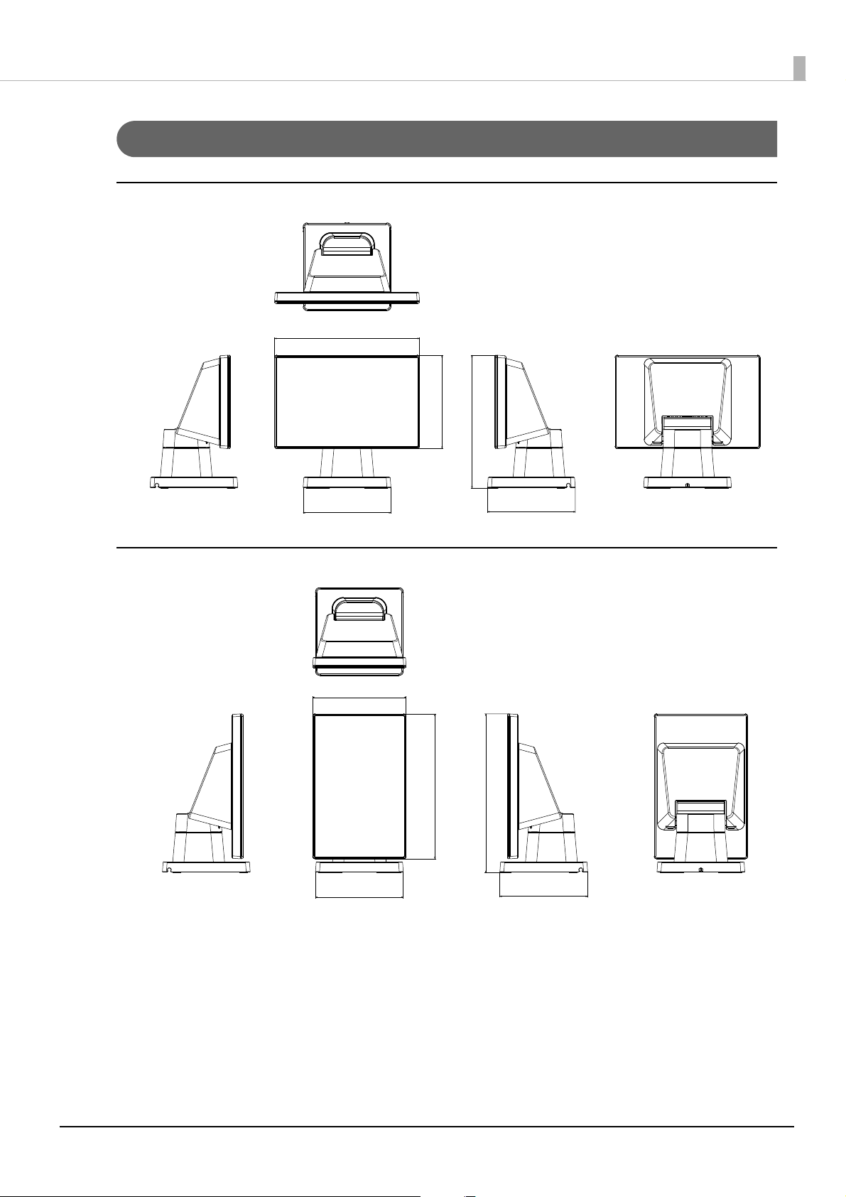
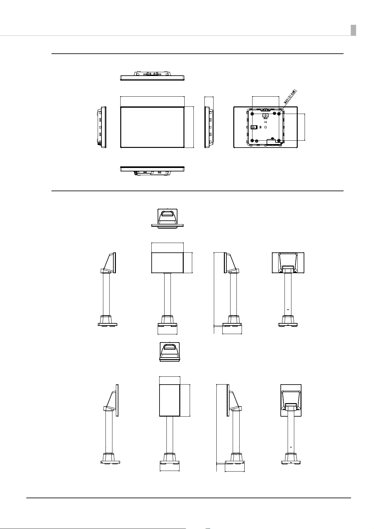
External Dimensions
180
109
109
116
165.2
[Unit: mm]
116
109
109
197.2
180
[Unit: mm]
When Installed in Landscape Orientation
Appendix
When Installed in Portrait Orientation
56
Page 57
Display Only
[Unit: mm]
116
412
180
109
109
4.7
[Unit: mm]
444
116
109
109
4.7
180
[Unit: mm]
Appendix
When Attached to DP-70
180
116
24.8
75
75
57
Page 58

When Attached to DP-71
180
353.4
334
245.8
116
[Unit: mm]
116
353.4
334
180
277.8
[Unit: mm]
Appendix
58
Page 59

Character Code Tables
Refer to the following URL regarding the Character Code Tables for Customer Displays.
U www.epson-biz.com/pos/reference/
Appendix
59
Page 60
Open Source Software Licenses
The product uses open source software in addition to software that Epson possesses. The following pieces of
open source software are used for this product.
Appendix
Name of
Software
zlib 1.2.8
libpng 1.6.14
IJG JPEG 9a
newlib 2.2.0
CMSIS-RTOS 4.80
lwIP 1.4.1
Renesas
Graphics
Architecture
FreeType 2 2.4.9
Vers ion of
Software
3.12
Usage
Redistributed
(binary)
Redistributed
(binary)
Redistributed
(binary)
Redistributed
(binary)
Redistributed
(binary)
Redistributed
(binary)
Redistributed
(binary)
Redistributed
(binary)
3rd Party
Code Licensor
zlib/libpng
License
(Compatible
with GPL)
PNG Reference
Library License
Libjpeg
License(BSDlike)
BSD 3-Clause
License
BSD 3-Clause
License
BSD 3-Clause
License
Renesas
Software
License
Agreement
Free Type
Projec t
LICENSE
Source Download URL License URL
https://www.renesas.com/jp/ja/
software/D6002383.html
https://www.renesas.com/jp/ja/
software/D6002383.html
https://www.renesas.com/jp/ja/
software/D6002383.html
https://www.sourceware.org/
newlib/
https://www.renesas.com/jp/ja/
software/D6003896.html
https://lwip.fandom.com/wiki/
LwIP_Wik i
https://www.renesas.com/jp/ja/
software/D6002383.html
https://www.freetype.org/
download.html
http://www.zlib.net/
zlib_license.html
http://www.libpng.org/pub/png/
src/libpng-LICENSE.txt
https://jpegclub.org/reference/
libjpeg-license/
https://www.sourceware.org/
newlib/COPYING.NEWLIB
an-r01an3638ej0212-rza1fwp\Software\CMSIS_RTOS_RTX\RT
OS\RTX\License.txt
(Included in the downloaded files)
https://lwip.fandom.com/wiki/
License
https://www.renesas.com/jp/ja/
common/disclaimers/
disclaimer002.html?disclaimer=discl
aimer002.html&targetUrl=L2NvbnRl
bnQvd3d3L2pwL2phL2Rvd25sb2Fk
L2pxX2Rvd25sb2FkX2NhdGVnb3J5L
3J6X2FwbG5vdGUvMDAxL3IwMWF
uMzYzOHh4MDIxMi1yemExLWZ3cC
56aXA/
a2V5PTZiMGNiMGFiNGIwMGJkNjJlN
2E0ZjRmZGVlMTlkZDBmJnRtcz1NVF
l3TVRRMk1qYzVNamcxTWc9PSZ0YX
JnZXRUeXBlPWRvd25sb2Fk&referer
=https://update.renesas.com/
&targetType=download
http://www.freetype.org/
license.html
60
 Loading...