

Page 1
Technical Reference Guide
Describes features for this product.
Describes how to install and set this product.
Describes the basic usage of this product.
Describes how to control this product and information
necessary for developing applications.
Describes the specications and character code tables.
Product Overview
Setup
Handling
Application Development Information
Appendix
M00093700
Rev. A
Page 2

Cautions
No part of this document may be reproduced, stored in a retrieval system, or transmitted in any form or by
any means, electronic, mechanical, photocopying, recording, or otherwise, without the prior written permission of Seiko Epson Corporation.
The contents of this document are subject to change without notice. Please contact us for the latest informa-
tion.
While every precaution has been taken in the preparation of this document, Seiko Epson Corporation
assumes no responsibility for errors or omissions.
Neither is any liability assumed for damages resulting from the use of the information contained herein.
Neither Seiko Epson Corporation nor its affiliates shall be liable to the purchaser of this product or third par-
ties for damages, losses, costs, or expenses incurred by the purchaser or third parties as a result of: accident,
misuse, or abuse of this product or unauthorized modifications, repairs, or alterations to this product, or
(excluding the U.S.) failure to strictly comply with Seiko Epson Corporation’s operating and maintenance
instructions.
Seiko Epson Corporation shall not be liable against any damages or problems arising from the use of any
options or any consumable products other than those specified as Original Epson Products or Epson
Approved Products by Seiko Epson Corporation.
Trademarks
EPSON is a registered trademark of Seiko Epson Corporation.
Exceed Your Vision and ESC/POS are registered trademarks or trademarks of Seiko Epson Corporation.
Microsoft and Windows are registered trademarks of Microsoft Corporation in the United States and/or other
countries.
IOS is a trademark or registered trademark of Cisco in the U.S. and other countries and is used under license.
Android is a trademark of Google, Inc..
Wi -F i
® is a registered trademark of Wi-Fi Alliance®.
All other trademarks are the property of their respective owners and used for identification purpose only.
ESC/POS Proprietary Command System
Epson took the initiative by introducing ESC/POS, a proprietary POS printer command system, which includes
patented or patent pending commands and enables versatile POS system construction with high scalability.
Compatible with all types of Epson POS printers and displays, this proprietary control system also offers the
flexibility to easily make future upgrades. Its popularity is worldwide.
ESC/POS is designed to reduce the processing load on the host computer in POS environments. It comprises a
set of highly functional and efficient commands that enables the full realization of the potential of printers.
© Seiko Epson Corporation 2015. All rights reserved.
2
Page 3
For Safety
Key to Symbols
The symbols in this manual are identified by their level of importance, as defined below. Read the following
carefully before handling the product.
You must follow warnings carefully to avoid serious bodily injury.
WARNING
Provides information that must be observed to prevent damage to the equipment or loss of data.
Possibility of sustaining physical injuries.
CAUTION
Possibility of causing physical damage.
Possibility of causing information loss.
Provides information that must be observed to avoid damage to your equipment or a malfunction.
Provides important information and useful tips.
Warnings
WARNING
Shut down your equipment immediately if it produces smoke, a strange odor, or unusual noise.
Continued use may lead to fire. Immediately disconnect the USB cable and contact your dealer
or a Seiko Epson service center for advice.
Never attempt to repair this product yourself. Improper repair work can be dangerous.
Never disassemble or modify this product. Tampering with this product may result in injury or
fire.
Do not allow foreign matter to fall into the equipment. Penetration by foreign objects may lead
to fire.
If water or other liquid spills into this equipment, disconnect the USB cable immediately, and
then contact your dealer or a Seiko Epson service center for advice. Continued usage may lead
to fire.
3
Page 4
Cautions
CAUTION
Do not connect cables and external interfaces in ways other than those mentioned in the man-
ual. Different connections may cause equipment damage and burning.
Be sure to set this equipment on a firm, stable, horizontal surface. The product may break or
cause injury if it falls.
Do not use in locations subject to high humidity or dust levels. Excessive humidity and dust may
cause equipment damage or fire.
Do not place heavy objects on top of this product. Never stand or lean on this product. Equip-
ment may fall or collapse, causing breakage and possible injury.
If you do not use this product for an extended period of time, always disconnect the USB cable
for safety. If you move the product, ensure that all of the cables are disconnected before moving
it.
Do not use aerosol sprayers containing flammable gas inside or around this product. Doing so
may cause fire.
4
Page 5

Restriction of Use
When this product is used for applications requiring high reliability/safety, such as transportation devices
related to aviation, rail, marine, automotive, etc.; disaster prevention devices; various safety devices, etc.; or
functional/precision devices, etc., you should use this product only after giving consideration to including failsafes and redundancies into your design to maintain safety and total system reliability. Because this product was
not intended for use in applications requiring extremely high reliability/safety, such as aerospace equipment,
main communication equipment, nuclear power control equipment, or medical equipment related to direct
medical care, etc., please make your own judgment on this product's suitability after a full evaluation.
About this Manual
Aim of the Manual
This manual provides the development engineers with necessary information for developing, designing, installing the system using DM-D30 as well as for developing and designing the applications.
Manual Content
The manual is made up of the following sections:
Chapter 1 Product Overview
Chapter 2 Setup
Chapter 3 Handling
Chapter 4 Application Development Information
Appendix Product Specifications
Charac
ter Code Tables
5
Page 6

6
Page 7

Contents
n For Safety..................................................................................................................................3
Key to Symbols.................................................................................................................................................................... 3
Warnings ............................................................................................................................................................................... 3
Cautions................................................................................................................................................................................. 4
n Restriction of Use ....................................................................................................................5
n About this Manual ..................................................................................................................5
Aim of the Manual ............................................................................................................................................................. 5
Manual Content .................................................................................................................................................................. 5
n Contents....................................................................................................................................7
Product Overview ..........................................................................................11
n Features ................................................................................................................................. 11
n Product Structure................................................................................................................. 11
Accessories .........................................................................................................................................................................11
n Part Names and Functions ................................................................................................. 12
n System Outline ..................................................................................................................... 13
Connecting with TM-m30 .............................................................................................................................................13
Connecting with Computer .........................................................................................................................................13
Setup ...............................................................................................................15
n Connecting to the Printer................................................................................................... 15
n Connecting to the Computer............................................................................................. 16
n Connecting the Printer’s Wireless LAN Unit.................................................................... 17
n Drawing Out the Cable........................................................................................................ 19
n Affixing the Customer Display........................................................................................... 20
n Memory Switch Setting ...................................................................................................... 21
Handling .........................................................................................................23
n Turning the Power On/Off .................................................................................................. 23
n Changing the Angle of the Display Unit.......................................................................... 23
n Adjusting the Contrast........................................................................................................ 23
n Cleaning the Customer Display......................................................................................... 24
7
Page 8

Application Development Information ...................................................... 25
n Controlling the Customer display..................................................................................... 25
ePOS-Print XML ................................................................................................................................................................25
ESC/POS .............................................................................................................................................................................. 25
n Software................................................................................................................................. 26
Development Kits ............................................................................................................................................................ 26
Drivers.................................................................................................................................................................................. 26
Manuals............................................................................................................................................................................... 27
Download........................................................................................................................................................................... 27
Appendix ........................................................................................................ 29
n Product Specifications ........................................................................................................ 29
Environmental Conditions ...........................................................................................................................................29
External Dimensions and Mass...................................................................................................................................30
n Character Code Tables......................................................................................................... 31
Common to All Pages..................................................................................................................................................... 31
Page 0 [PC437: USA, Standard Europe].................................................................................................................... 32
Page 1 (Katakana) ............................................................................................................................................................ 33
Page 2 (PC850: Multilingual)........................................................................................................................................ 34
Page 3 (PC860: Portuguese)......................................................................................................................................... 35
Page 4 (PC863: Canadian-French)..............................................................................................................................36
Page 5 (PC865: Nordic) .................................................................................................................................................. 37
Page 11 (PC851: Greek).................................................................................................................................................. 38
Page 12 (PC853: Turkish)...............................................................................................................................................39
Page 13 (PC857: Turkish)...............................................................................................................................................40
Page 14 (PC737: Greek).................................................................................................................................................. 41
Page 15 (ISO8859-7: Greek).......................................................................................................................................... 42
Page 16 (WPC1252)......................................................................................................................................................... 43
Page 17 (PC866: Cyrillic #2) .......................................................................................................................................... 44
Page 18 (PC852: Latin 2)................................................................................................................................................ 45
Page 19 (PC858: Euro) .................................................................................................................................................... 46
Page 30 (TCVN-3: Vietnamese) ...................................................................................................................................47
Page 31 (TCVN-3: Vietnamese) ...................................................................................................................................48
Page 32 (PC720: Arabic)................................................................................................................................................. 49
Page 33 (WPC775: Baltic Rim) .....................................................................................................................................50
Page 34 (PC855: Cyrillic) ................................................................................................................................................ 51
Page 35 (PC861: Icelandic)............................................................................................................................................ 52
Page 36 (PC862: Hebrew).............................................................................................................................................. 53
Page 37 (PC864: Arabic)................................................................................................................................................. 54
Page 38 (PC869: Greek).................................................................................................................................................. 55
Page 39 (ISO8859-2: Latin 2) ........................................................................................................................................ 56
Page 40 (ISO8859-15: Latin 9) .....................................................................................................................................57
Page 41 (PC1098: Farsi).................................................................................................................................................. 58
Page 42 (PC1118: Lithuanian) ..................................................................................................................................... 59
Page 43 (PC1119: Lithuanian) ..................................................................................................................................... 60
Page 44 (PC1125: Ukrainian)........................................................................................................................................ 61
8
Page 9

Page 45 (WPC1250: Latin 2)..........................................................................................................................................62
Page 46 (WPC1251: Cyrillic)..........................................................................................................................................63
Page 47 (WPC1253: Greek) ...........................................................................................................................................64
Page 48 (WPC1254: Turkish).........................................................................................................................................65
Page 49 (WPC1255: Hebrew) .......................................................................................................................................66
Page 50 (WPC1256: Arabic) ..........................................................................................................................................67
Page 51 (WPC1257: Baltic Rim) ...................................................................................................................................68
Page 52 (WPC1258: Vietnamese)................................................................................................................................69
Page 53 (KZ1048: Kazakhstan) ....................................................................................................................................70
Page 254 (User-Defined Page).....................................................................................................................................71
Page 255 (User-Defined Page).....................................................................................................................................72
International Character Sets.........................................................................................................................................73
9
Page 10

10
Page 11

Chapter 1 Product Overview
Product Overview
This chapter describes features of the product.
Features
DM-D30 is a customer display for displaying characters. The main features of this product are as follows.
Display
20 digit x 2 lines dot matrix for displaying half-width characters.
Usability
Compact.
You can move the display section up and down to adjust the position so it is easy to see.
Power supply to the product is USB bus power.
Interface
By connecting to the TM-m30 USB connector (for connecting a Wireless LAN unit), you can control the
printer using a smart device (iOS, Android, and Windows).
You can connect to the TM-m30 USB connector (for connecting a Wireless LAN unit), and a Windows PC
USB connector.
When connecting to the TM-m30’s dedicated USB connector (for connecting a Wireless LAN unit), you can
mount the TM-m30’s Wireless LAN unit to the DM-D30’s Wireless LAN unit connector.
Product Structure
1
Accessories
Included
Affixing tape
Manual
11
Page 12
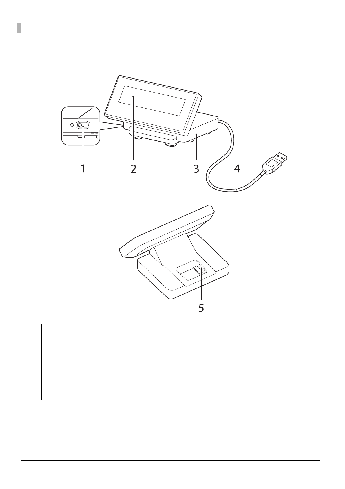
Part Names and Functions
12
1 Contrast adjustment control Move this to adjust the contrast of the LCD screen.
2 Display Displays on the LCD screen. You can adjust the angle of the display.
Note:
The display is covered with a protective film. Remove it if necessary.
3 Stand Supports the display unit. Place it on a flat surface.
4 USB cable Use to connect to the printer or a computer.
5 Wireless LAN unit connector Use to connect the Wireless LAN unit that is pre-installed to the printer’s USB
connector, when connecting to a Wi-Fi
®
model printer.
Page 13

System Outline
DM-D30
TM-m30
DM-D30
Computer
USB
This section explains the system connection pattern using this product.
Connecting with TM-m30
Connect this product’s USB cable to the TM-m30. Power is supplied from the TM-m30.
Chapter 1 Product Overview
1
Connecting with Computer
Connect this product’s USB cable to the computer. Power is supplied from the computer.
When connecting to a bus power hub, this product may not always operate.
Install the driver you are using before connecting.
13
Page 14

14
Page 15
Setup
This chapter explains the installation and setting operations necessary to use this product.
Connecting to the Printer
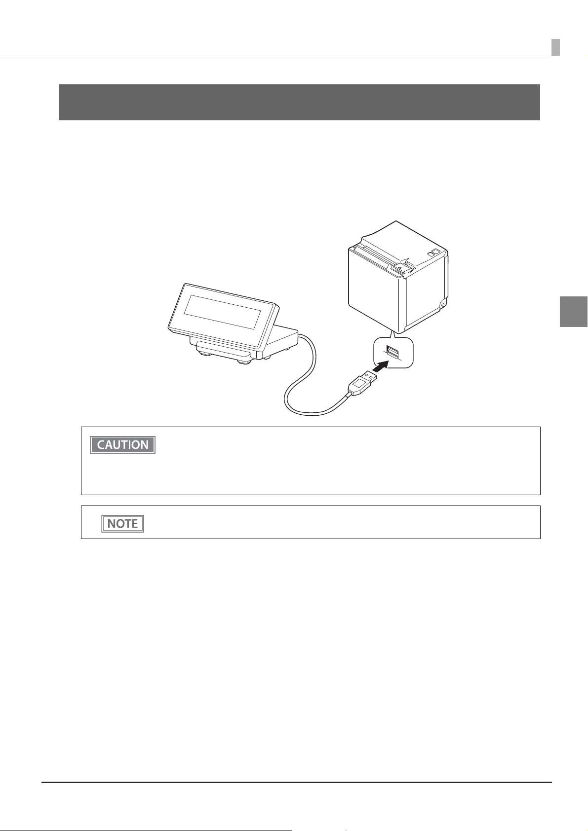
Connect the USB cable of the customer display to the USB connector on the printer.
Chapter 2 Setup
2
When you connect the USB cable to the printer, be sure to turn off the printer before connect-
ing.
We do not recommend using this USB bus power device with a USB extension cable. Depending
on the configuration of the cable, operational errors or a deterioration in EMC characteristics
may occur due to a drop in voltage.
For the position of connectors on the printer and so on, see the documentation provided with the
printer.
15
Page 16
Connecting to the Computer
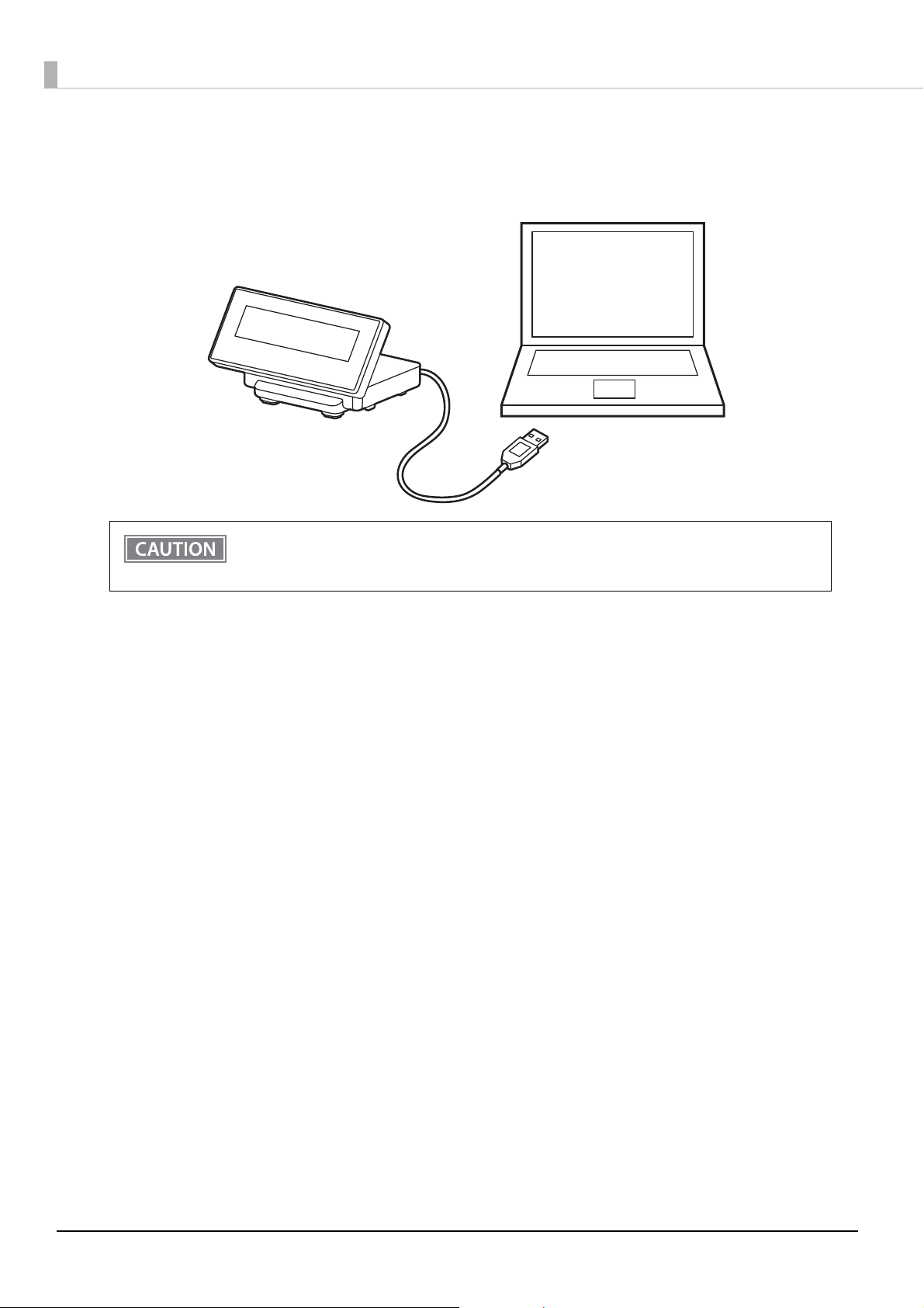
Connect the USB cable of the customer display to the USB connector on the computer.
We do not recommend using this USB bus power device with a USB extension cable. Depending on
the configuration of the cable, operational errors or a deterioration in EMC characteristics may
occur due to a drop in voltage.
16
Page 17
Chapter 2 Setup
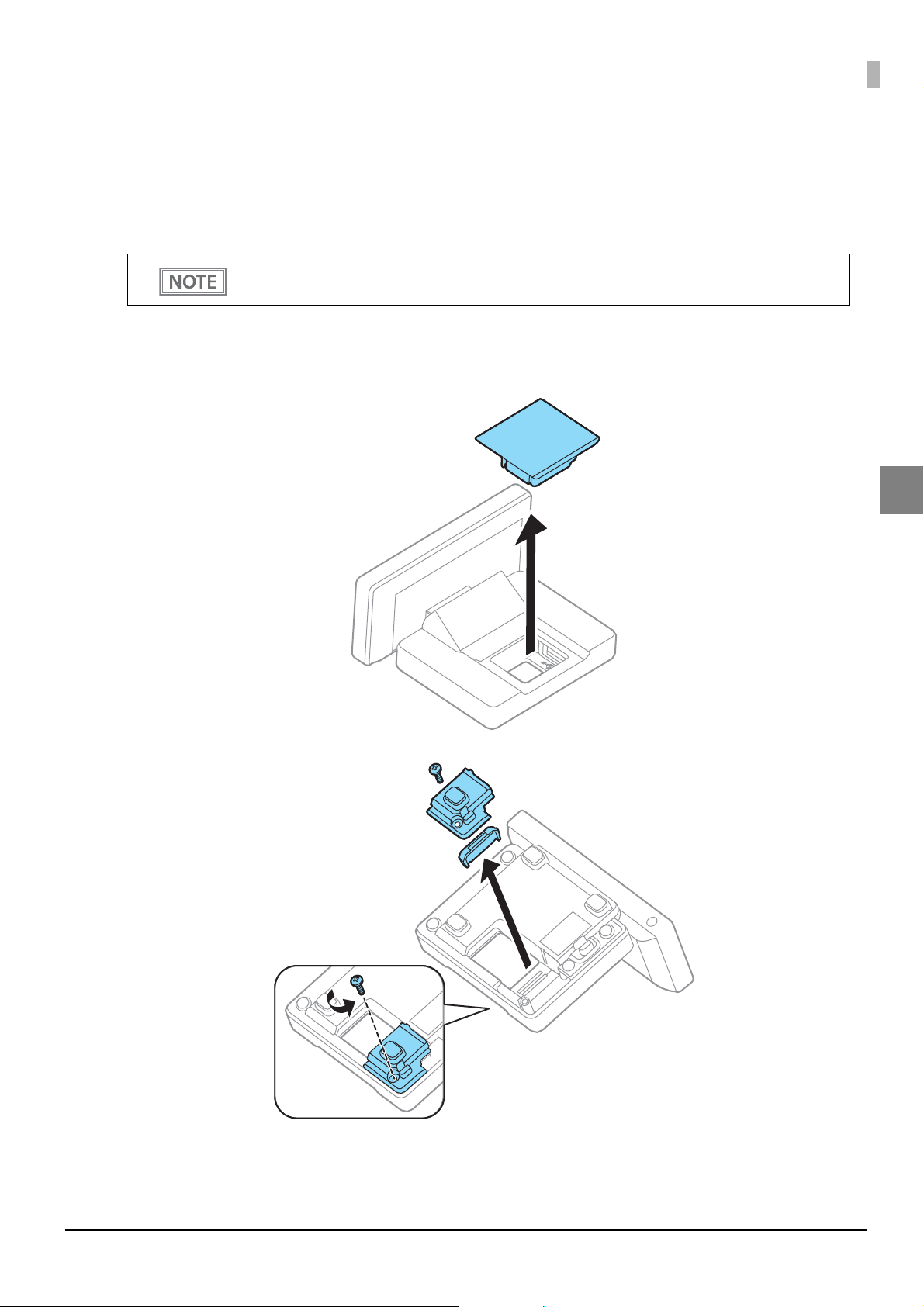
Connecting the Printer’s Wireless LAN Unit
When the Wireless LAN unit is connected to the printer's USB connector and there are no free USB connectors,
you can use the Wireless LAN unit and the customer display at the same time by connecting the Wireless LAN
unit to the Wireless LAN unit connector on this device.
You can only use the optional Wireless LAN unit supported by the TM printer.
Follow the steps below to connect the Wireless LAN unit to the device's Wireless LAN unit connector.
Remove the covers for the top and bottom of the stand as shown in the illustration.
1
2
17
Page 18
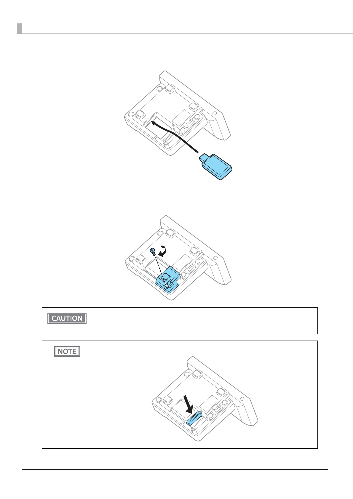
Connect the Wireless LAN unit to the Wireless LAN unit connector.
2
Reattach the cover for the bottom. Keep the cover for the stand removed.
3
18
Do not place anything in the upper section (cover opening) of the Wireless LAN unit. If heat is
not allowed to dissipate when using the product, it may lead to a malfunction.
Do not use a USB extension cable. Operational errors may occur due to a drop in voltage.
Install dividers if necessary depending on the length of the Wireless LAN unit.
Page 19
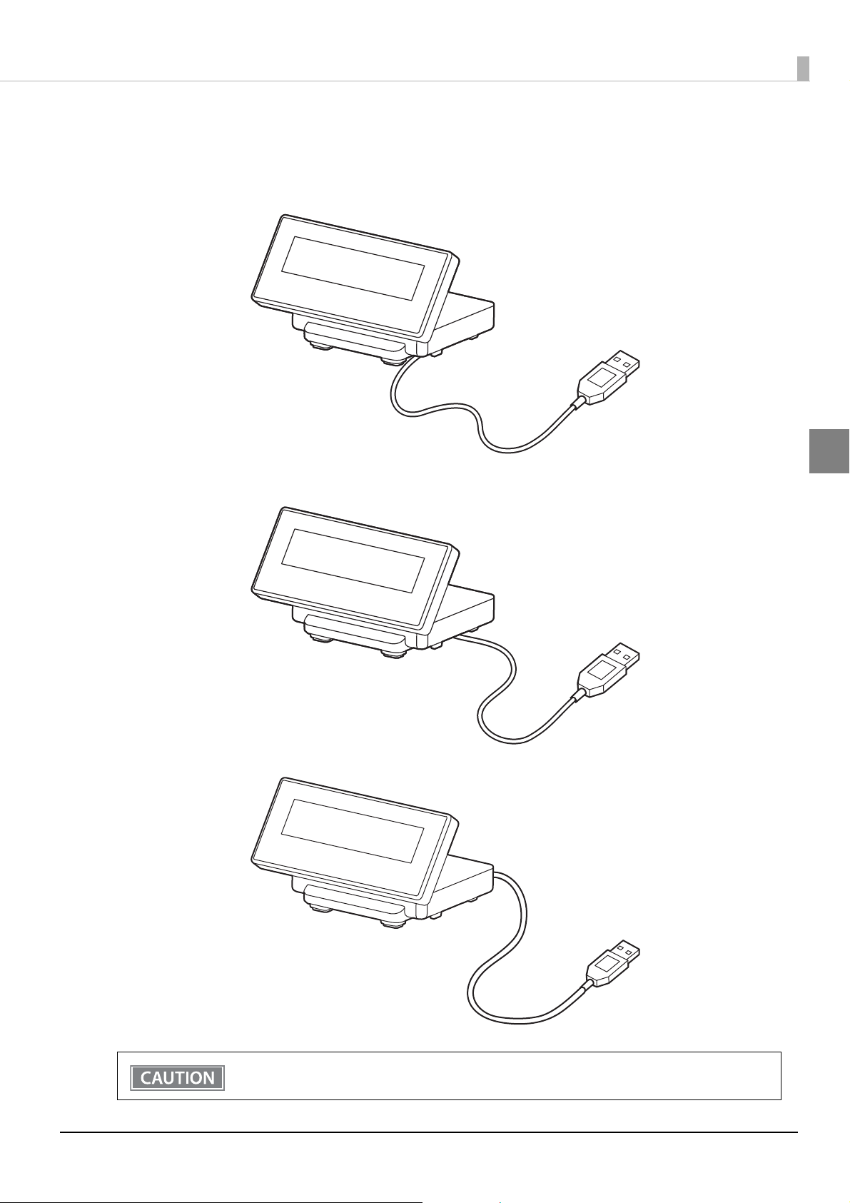
Drawing Out the Cable
You can draw out the USB cable from the front, the side, or the back.
Chapter 2 Setup
2
Be sure to turn off the power on the printer when connecting USB cable to the printer.
19
Page 20
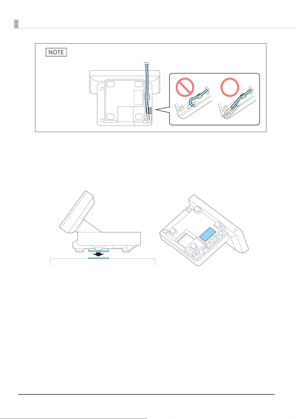
If you draw the cable from the front, fold the cable back inside the hollow of the stand, and then
secure the cable as shown in the illustration, so that it does not become loose.
Affixing the Customer Display
You can use the affixing tape supplied to secure the device.
Attach the affixing tape to the points shown in the following illustration.
20
Page 21
Chapter 2 Setup
Memory Switch Setting
This product comes with memory switches as part of the software's setting features. These allow you to make
settings for the TM-m30 Utility.
For details, see the TM-m30 Utility User's Manual.
Turn Off Backlight
Select from 0 to 120 seconds
Initial setting: Normally On
Code-page
Specify from 40 code pages and custom pages
Initial setting: 0 (PC437:USA,Standard Europe)
2
International character set
Specify from 18 sets
Initial setting: 0 (USA)
Adjust Brightness
Select from 1 (20%) to 4 (100%)
Initial setting: 4 (100%)
Cursor Display
- 0: Cursor not displayed
- 1: Cursor displayed
- 48: Cursor not displayed
- 49: Cursor displayed
Initial setting: 0
Display No.
Select from 0 to 255
Initial setting: 0
21
Page 22

22
Page 23
Chapter 3 Handling
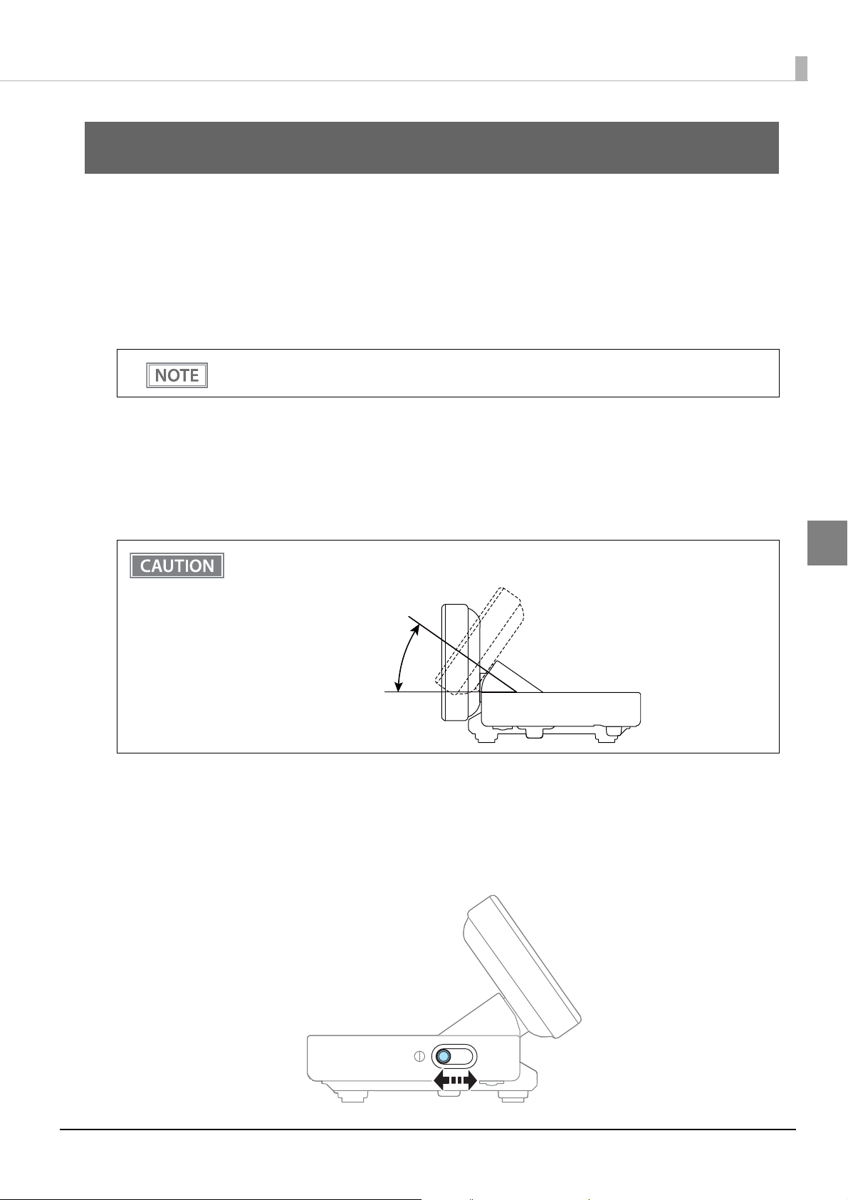
35°
Handling
This chapter explains the basic handling methods for this product.
Turning the Power On/Off
The power for this product is supplied by USB bus power, which means that the power is supplied from the connected printer or computer through the USB connector.
To turn this product on or off, turn the connected printer or computer on or off.
The display may not turn off while the power is still supplied to USB connector, even if the printer's
Power LED is off.
Changing the Angle of the Display Unit
You can change the angle of the display unit by holding the stand with your hand while moving the display unit.
The following shows the range of motion.
Do not exceed the range of motion when moving the display unit. Applying excess force when
moving the display unit may cause damage.
Adjusting the Contrast
You can adjust the contrast of the LCD screen by sliding the contrast adjustment control on the side of the
stand.
3
23
Page 24

Cleaning the Customer Display
Be sure to disconnect the USB cable from the printer, and then wipe the dirt off the outer case with a dry cloth
or a damp cloth.
Never clean the product with alcohol, benzine, thinner, or other such solvents. Doing so may
damage or break the parts made of plastic and rubber.
Rubbing the LCD screen with too much force using a dry cloth may scratch the surface.
24
Page 25

Chapter 4 Application Development Information
Application Development Information
This chapter explains how to control the customer display as well as necessary information for developing system applications using this product.
Controlling the Customer display
The this product supports the following command systems:
ePOS-Print XML
ESC/POS
Users can control the customer display by using the aforementioned commands, or the following development
kits or drivers.
Epson ePOS SDK
EPSON OPOS ADK
EPSON OPOS ADK for .NET
EPSON JavaPOS ADK
EPSON Advanced Printer Driver Ver.5 (APD5)
ePOS-Print XML
ePOS-Print XML is Epson's control command system for the customer display defined in XML. You can print
from the socket communication environment or OS applications. For details of ePOS-Print XML, see the
ePOS-Print XML User’s Manual.
ePOS-Print XML can be used when this product is connected to the TM printer.
ESC/POS
ESC/POS is the Epson original printer command system for POS printers and customer display. With ESC/POS
commands, you can directly control all the this product functions, but detailed knowledge of printer specifications or combination of commands is required, compared to using drivers and applications.
For details on ESC/POS, see the specifications for this product. You need a contract separately to acquire the
specifications. For details, contact the store of your purchase.
4
25
Page 26

Software
The following software are provided for application development.
Development Kits
Software Description
Epson ePOS SDK Development kit for controlling the POS peripheral devices such as the printer and
for iOS
for Android
TM
customer display from the Web application or native application for smart devices.
It includes libraries, manuals, and sample programs.
EPSON OPOS ADK OCX driver that controls the POS peripheral devices such as the customer display
using the OLE technologies
Because controlling POS peripherals with original commands is not required on the
application side, efficient system development is possible.
EPSON OPOS ADK
for .NET
EPSON JavaPOS ADK JavaPOS ADK is a UPOS driver in Java environment. You can develop applications
The OPOS ADK for .NET is a POS industry standard printer driver compatible with
Microsoft POS for .NET.
It allows you to develop applications that are compatible with the UPOS (Unified
POS) specification.
When developing applications, use a separate development environment such as
Microsoft Visual Studio .NET.
based on the UPOS (UnifiedPOS) specifications.
*
.
OLE technology developed by Microsoft divides software into part blocks.
EPSON OPOS ADK, EPSON OPOS ADK for .NET, and EPSON JavaPOS ADK are only supported when
connecting through TM-m30.
Drivers
Software Description
Operating
environment
EPSON Advanced Printer Driver
Ver.5 (APD5)
TM Virtual Port Driver Connect the USB directly to the PC, and use this when con-
Windows printer driver that can display on the customer display. You cannot send ESC/POS commands to the customer display or monitor the status.
trolling using ESC/POS commands.
This driver allows you to recognize customer displays connected by USB as a virtual serial port.
26
Windows
Windows
Page 27

Manuals
Software Description
Chapter 4 Application Development Information
Each TM printer's Technical Reference Guide
ePOS-Print XML Use’s Manual Describes ePOS-Print XML statements. This manual comes with sample programs.
TM printer's Technical Reference Guide explains about the necessary information for
developing, designing, installing the POS system using the TM printers, or for developing and designing the printer applications.
Download
You can obtain software and manuals from one of the following URLs.
For customers in North America, go to the following web site and follow the on-screen instructions.
http://www.epsonexpert.com/
For customers in other countries, go to the following web site:
http://download.epson-biz.com/?service=pos
4
27
Page 28

28
Page 29

Appendix
Product Specifications
Appendix
Display type STN LCD (160 x 32 dots)
Number of characters displayed 40 characters (20 columns x 2 rows)
Display color White/Blue
Brightness 100 cd/m2
Character classes Alphanumeric: 95 characters (8 x 16 dots)
International characters: 18 sets (8 x 16 dots)
Graphic characters: 128 characters x 41 pages
Character size 4.1 x 8.3 mm {0.16 x 0.33"} (W x H, alphanumeric)
Character pitch 4.7 mm {0.19"}
Interface USB USB 2.0 High/Full speed
(Display: Full speed, connector for Wireless LAN unit: High/Full speed)
Reliability Lifespan 50,000 hours
Input voltage DC 4.75 to 5.25 V (Operates with USB bus power)
Current consumption 0.2 A (Wireless LAN unit not connected)
0.7 A (Wireless LAN unit connected)
*
Angle of the Display Unit 0 - 35
Power supply USB bus power
: Since a characteristic of the STN LCD is that it has a longer response time (when switching dots On/Off) com-
pared to VFD display tubes (DM-D110 etc.), it becomes harder to display marquees that have a short interval for
text display (horizontal scrolling).
When displaying a marquee (horizontal scrolling), we recommend taking into account the display response time
for the LCD (250 to 350 msec), and set the text display interval to 600 msec or more.
Environmental Conditions
Item Specification
Temperature Operating: 5 to 45 °C {41 to 113 °F}
Storage: -10 to 50 °C {14 to 122 °F}
Humidity Operating: 10 to 90 % (non-condensing)
Storage: 10 to 90 % (non-condensing)
29
Page 30

External Dimensions and Mass
[Unit: mm]
Item Specification
Width 130 mm (5.12 inches)
Depth 100 mm (3.94 inches)
Height 68 mm (2.68 inches)
Mass 0.3 kg
When the angle of display unit is 0 degree.
102
130
100
68
30
Page 31

Character Code Tables
The character code tables show only character configurations. They do not show the actual print
pattern.
“SP” in the table shows a space.
Common to All Pages
When the international character set (See "International Character Sets" on page 73.) is USA:
Appendix
31
Page 32

Page 0 [PC437: USA, Standard Europe]
32
Page 33

Page 1 (Katakana)
Appendix
33
Page 34

Page 2 (PC850: Multilingual)
34
Page 35

Page 3 (PC860: Portuguese)
Appendix
35
Page 36

Page 4 (PC863: Canadian-French)
36
Page 37

Page 5 (PC865: Nordic)
Appendix
37
Page 38

Page 11 (PC851: Greek)
38
Page 39

Page 12 (PC853: Turkish)
Appendix
39
Page 40

Page 13 (PC857: Turkish)
40
Page 41

Page 14 (PC737: Greek)
Appendix
41
Page 42

Page 15 (ISO8859-7: Greek)
42
Page 43

Page 16 (WPC1252)
Appendix
43
Page 44

Page 17 (PC866: Cyrillic #2)
44
Page 45

Page 18 (PC852: Latin 2)
Appendix
45
Page 46

Page 19 (PC858: Euro)
46
Page 47

Page 30 (TCVN-3: Vietnamese)
Appendix
47
Page 48

Page 31 (TCVN-3: Vietnamese)
48
Page 49

Page 32 (PC720: Arabic)
Appendix
49
Page 50

Page 33 (WPC775: Baltic Rim)
50
Page 51

Page 34 (PC855: Cyrillic)
Appendix
51
Page 52

Page 35 (PC861: Icelandic)
52
Page 53

Page 36 (PC862: Hebrew)
Appendix
53
Page 54

Page 37 (PC864: Arabic)
54
Page 55

Page 38 (PC869: Greek)
Appendix
55
Page 56

Page 39 (ISO8859-2: Latin 2)
56
Page 57

Page 40 (ISO8859-15: Latin 9)
Appendix
57
Page 58

Page 41 (PC1098: Farsi)
58
Page 59

Page 42 (PC1118: Lithuanian)
Appendix
59
Page 60

Page 43 (PC1119: Lithuanian)
60
Page 61

Page 44 (PC1125: Ukrainian)
Appendix
61
Page 62

Page 45 (WPC1250: Latin 2)
62
Page 63

Page 46 (WPC1251: Cyrillic)
Appendix
63
Page 64

Page 47 (WPC1253: Greek)
64
Page 65

Page 48 (WPC1254: Turkish)
Appendix
65
Page 66

Page 49 (WPC1255: Hebrew)
66
Page 67

Page 50 (WPC1256: Arabic)
Appendix
67
Page 68

Page 51 (WPC1257: Baltic Rim)
68
Page 69

Page 52 (WPC1258: Vietnamese)
Appendix
69
Page 70

Page 53 (KZ1048: Kazakhstan)
70
Page 71

Page 254 (User-Defined Page)
Appendix
71
Page 72

Page 255 (User-Defined Page)
72
Page 73

International Character Sets
Appendix
73
Page 74

74
 Loading...