

Page 1
DM-D110
Technical Reference
guide
EPSON
English
410826900
Rev.A
Page 2

Page 3

DM-D110 Technical Reference Guide
CAUTIONS
❏ This document shall apply only to the product(s) identified herein.
❏ No part of this document may be reproduced, stored in a retrieval system, or transmitted in any form or by any
means, electronic, mechanical, photocopying, recording, or otherwise, without the prior written permission of
Seiko Epson Corporation.
❏ The contents of this document are subject to change without notice. Please contact us for the latest information.
❏ While every precaution has been taken in the preparation of this document, Seiko Epson Corporation assumes no
responsibility for errors or omissions.
❏ Neither is any liability assumed for damages resulting from the use of the information contained herein.
❏ Neither Seiko Epson Corporation nor its affiliates shall be liable to the purchaser of this product or third parties
for damages, losses, costs, or expenses incurred by the purchaser or third parties as a result of: accident, misuse, or
abuse of this product or unauthorized modifications, repairs, or alterations to this product, or (excluding the U.S.)
failure to strictly comply with Seiko Epson Corporation's operating and maintenance instructions.
❏ Seiko Epson Corporation shall not be liable against any damages or problems arising from the use of any options
or any consumable products other than those designated as Original EPSON Products or EPSON Approved
Products by Seiko Epson Corporation.
TRADEMARKS
EPSON® and ESC/POS® are registered trademarks of Seiko Epson Corporation.
Microsoft
General Notice: Other product and company names used herein are for identification purposes only and may be
trademarks of their respective companies.
®
Windows® and Windows NT® are registered trademarks of Microsoft Corporation.
ESC/POS Proprietary Command System
EPSON took the initiative by introducing ESC/POS, a proprietary POS printer command system including patented
commands and enabling versatile POS system construction with high scalability. Compatible with all types of EPSON
POS printers and displays, this proprietary control system also offers the flexibility to easily make future upgrades. Its
popularity is worldwide.
Revision Information
Revision Page Altered Items and Contents
Rev. A all pages Newly authorized
Rev. A i
Page 4

Related Software and Documents
Related software and documents
Software/document name Description
DM-D110 User’s Manual/ This provides basic handling procedures for the end user of the
DM-D110 Technical Reference Guide This Manual
ESC/POS Application Programming Guide This provides descriptions in Acrobat format of the commands
EPSON OPOS ADK This is a OCX driver
EPSON OPOS ADK Manual This provides information for anyone who is programming using
EPSON Advanced Printer Driver This is a Windows driver
EPSON Advanced Printer Driver Manual This provides information for anyone who is programming using
Guide for DM-D110 right side up printing This provides information on the DM-D110 printer for anyone who
printer
used by each TM printer, along with sample programs and other
information about the printers
OPOS. This is included in the EPSON OPOS ADK
the APD (EPSON Advanced Printer Driver)
is using the right side up printing mode.
ii Rev. A
Page 5

DM-D110 Technical Reference Guide
Safety Precautions
All rights reserved. No part of this publication may be reproduced, stored in a retrieval system, or transmitted in any
form or by any means, electronic, mechanical, photocopying, recording, or otherwise, without the prior written
permission of Seiko Epson Corporation. No patent liability is assumed with respect to the use of the information
contained herein. While every precaution has been taken in the preparation of this book, Seiko Epson Corporation
assumes no responsibility for errors or omissions. Neither is any liability assumed for damages resulting from the use
of the information contained herein.
Neither Seiko Epson Corporation nor its affiliates shall be liable to the purchaser of this product or third parties for
damages, losses, costs, or expenses incurred by purchaser or third parties as a result of: accident, misuse, or abuse of
this product or unauthorized modifications, repairs, or alterations to this product, or (excluding the U.S.) failure to
strictly comply with Seiko Epson Corporation’s operating and maintenance instructions.
Seiko Epson Corporation shall not be liable against any damages or problems arising from the use of any options or
any consumable products other than those designated as Original Epson Products or Epson Approved Products by
Seiko Epson Corporation.
EPSON and ESC/POS are registered trademarks of Seiko Epson Corporation in the U.S. and other countries.
NOTICE:
The contents of this manual are subject to change without notice.
Copyright © 2006 by Seiko Epson Corporation, Nagano, Japan.
EMC and Safety Standards Applied
EMC and Safety Standards Applied
Product Name: DM-D110/DM-D210
Model Name: M58DB/M59DB
The following standards are applied only to the display that is so labeled. (EMC is tested using the EPSON power
supplies.)
Europe: CE marking
Safety: EN 60950-1
North America: EMI: FCC/ICES-003 Class A
Safety: UL 90650-1/CSA C22.2
No. 60950-1
Japan: EMC: VCCI Class A
Oceania: EMC: AS/NZS CISPR22 Class B
WARNING
You are cautioned that changes or modifications not expressly approved by SEIKO EPSON Corporation could void
your authority to operate the equipment.
CE Marking
The display conforms to the following Directives and Norms:
Directive 89/336/EEC
EN 55022 Class B
EN 55024
IEC 61000-4-2
IEC 61000-4-3
IEC 61000-4-4
IEC 61000-4-5
IEC 61000-4-6
IEC 61000-4-11
Rev. A iii
Page 6

FCC Compliance Statement For American Users
This equipment has been tested and found to comply with the limits for a Class A digital device, pursuant to Part 15 of
the FCC Rules. These limits are designed to provide reasonable protection against harmful interference when the
equipment is operated in a commercial environment.
This equipment generates, uses, and can radiate radio frequency energy and, if not installed and used in accordance
with the instruction manual, may cause harmful interference to radio communications.
Operation of this equipment in a residential area is likely to cause harmful interference, in which case the user will be
required to correct the interference at his own expense.
FOR CANADIAN USERS
This Class A digital apparatus complies with Canadian ICES-003.
À l'intention des utilisateurs canadiens
Cet appareil numerique de la classe A est conforme a la norme NMB-003 du Canada.
GERAUSCHPEGEL
Gemas der Dritten Verordnung zum Geratesicherheitsgesetz (Maschinenlarminformations- Verordnung-3. GSGV) ist
der arbeitsplatzbezogene Gerausch-Emissionswert kleiner als 70 dB(A) (basierend auf ISO 7779).
Key to Symbols
The symbols in this manual are identified by their level of importance, as defined below. Read
the following carefully before handling the product.
WARNING:
Warnings must be followed carefully to avoid serious bodily injury.
CAUTION:
Cautions must be observed to avoid minor injury to yourself or damage to your
equipment.
Note:
Notes have important information and useful tips on the operation of your equipment.
Safety Precautions
This section presents important information to ensure safe and effective use of this product.
Please read this section carefully and store it in an accessible location.
WARNING:
❏
Shut down your equipment immediately if it produces smoke, a strange odor, or
unusual noise. Continued use may lead to fire. Immediately unplug the equipment
and contact your dealer or a Seiko Epson service center for advice.
❏
Never attempt to repair this product yourself. Improper repair work can be
dangerous.
iv Rev. A
Page 7

DM-D110 Technical Reference Guide
❏
Never disassemble or modify this product. Tampering with this product may result in
injury or fire.
❏
Be sure to use the specified power source. Connection to an improper power source
may cause fire.
❏
Do not allow foreign matter to fall into the equipment. Penetration by foreign
objects may lead to fire.
❏
If water or other liquid spills into this equipment, unplug the power cord immediately,
and then contact your dealer or a Seiko Epson service center for advice. Continued
usage may lead to fire.
CAUTION:
❏
Do not connect cables in ways other than those mentioned in this manual. Different
connections may cause equipment damage and burning.
❏
Be sure to set this equipment on a firm, stable, horizontal surface. The product may
break or cause injury if it falls.
❏
Do not use in locations subject to high humidity or dust levels. Excessive humidity and
dust may cause equipment damage or fire.
❏
Do not place heavy objects on top of this product. Never stand or lean on this
product. Equipment may fall or collapse, causing breakage and possible injury.
❏
Do not connect multiple extension struts. If the device topples over, there is a risk of
damage or injury.
❏
The horizontal rotating angle of the screen unit is limited by a stopper. Do not apply
excess force to rotate the screen unit past the limit set by the stopper. Doing so may
cause damage.
❏
When you are attaching and detaching the cable, always check that the power
switches of the customer display and the unit that it is connected to are turned off.
❏
Take care when handling the customer display not to drop or knock it because it has
a built-in fluorescent display tube.
❏
If you do not use this product for an extended period of time, always disconnect the
power cord for safety. If you move the product, ensure that the power cord is
disconnected and that all of the cables are disconnected before moving it.
❏
Do not use aerosol sprayers containing flammable gas inside or around this product.
Doing so may cause fire.
Rev. A v
Page 8

About This Manual
Aim of the Manual
This manual was created to provide information on the DM-D110 customer display for anyone
who is developing hardware, installations, or programs. Programmers will also want to consult
other documents.
Contents of the Manual
Chapter 1, “General Information.” General description of features plus
specifications.
Chapter 2, “Setup information.” Describes product DM-D110 setup.
Chapter 3, “DIP Switches.” Describes product DIP Switch settings.
Chapter 4, “Hardware.” Describes produc signal connections of the
interface and data flow.
Chapter 5, “Application Development
Information.”
Appendix A, “Character Code Tables.” Character Code Tables
Describes how to control the customer display.
vi Rev. A
Page 9

DM-D110 Technical Reference Guide
Contents
Revision Information . . . . . . . . . . . . . . . . . . . . . . . . . . . . . . . . . . . . . . . . . . . . . . . . . . . . . . . . . . . . . . . . . . . . . . . . . . . . i
Related Software and Documents . . . . . . . . . . . . . . . . . . . . . . . . . . . . . . . . . . . . . . . . . . . . . . . . . . . . . . . . . . . . . . ii
EMC and Safety Standards Applied . . . . . . . . . . . . . . . . . . . . . . . . . . . . . . . . . . . . . . . . . . . . . . . . . . . . . . . . . . . . . . . . iii
Key to Symbols . . . . . . . . . . . . . . . . . . . . . . . . . . . . . . . . . . . . . . . . . . . . . . . . . . . . . . . . . . . . . . . . . . . . . . . . . . . . . iv
Safety Precautions . . . . . . . . . . . . . . . . . . . . . . . . . . . . . . . . . . . . . . . . . . . . . . . . . . . . . . . . . . . . . . . . . . . . . . . . . . . iv
About This Manual . . . . . . . . . . . . . . . . . . . . . . . . . . . . . . . . . . . . . . . . . . . . . . . . . . . . . . . . . . . . . . . . . . . . . . . . . . . . . . vi
Aim of the Manual . . . . . . . . . . . . . . . . . . . . . . . . . . . . . . . . . . . . . . . . . . . . . . . . . . . . . . . . . . . . . . . . . . . . . . . . . . . vi
Contents of the Manual . . . . . . . . . . . . . . . . . . . . . . . . . . . . . . . . . . . . . . . . . . . . . . . . . . . . . . . . . . . . . . . . . . . . . . . vi
Contents . . . . . . . . . . . . . . . . . . . . . . . . . . . . . . . . . . . . . . . . . . . . . . . . . . . . . . . . . . . . . . . . . . . . . . . . . . . . . . . . . . . vii
Chapter 1
Chapter 1 General Information
Chapter 1 Chapter 1
Features . . . . . . . . . . . . . . . . . . . . . . . . . . . . . . . . . . . . . . . . . . . . . . . . . . . . . . . . . . . . . . . . . . . . . . . . . . . . . . . . . . . . . . . . 1-1
Installation Example . . . . . . . . . . . . . . . . . . . . . . . . . . . . . . . . . . . . . . . . . . . . . . . . . . . . . . . . . . . . . . . . . . . . . . . . . . . . . 1-2
Connection Example . . . . . . . . . . . . . . . . . . . . . . . . . . . . . . . . . . . . . . . . . . . . . . . . . . . . . . . . . . . . . . . . . . . . . . . . . . . . . 1-2
Pass-through Connection . . . . . . . . . . . . . . . . . . . . . . . . . . . . . . . . . . . . . . . . . . . . . . . . . . . . . . . . . . . . . . . . . . . . . 1-2
Stand-Alone Connection . . . . . . . . . . . . . . . . . . . . . . . . . . . . . . . . . . . . . . . . . . . . . . . . . . . . . . . . . . . . . . . . . . . . . . 1-3
Y-type Connection . . . . . . . . . . . . . . . . . . . . . . . . . . . . . . . . . . . . . . . . . . . . . . . . . . . . . . . . . . . . . . . . . . . . . . . . . . . 1-3
System Requirements . . . . . . . . . . . . . . . . . . . . . . . . . . . . . . . . . . . . . . . . . . . . . . . . . . . . . . . . . . . . . . . . . . . . . . . . . . . . 1-4
System Planning . . . . . . . . . . . . . . . . . . . . . . . . . . . . . . . . . . . . . . . . . . . . . . . . . . . . . . . . . . . . . . . . . . . . . . . . . . . . . . . . 1-4
Chapter 2
Chapter 2 Setup information
Chapter 2 Chapter 2
Cautions on Handling . . . . . . . . . . . . . . . . . . . . . . . . . . . . . . . . . . . . . . . . . . . . . . . . . . . . . . . . . . . . . . . . . . . . . . . . . . . . 2-1
Usage . . . . . . . . . . . . . . . . . . . . . . . . . . . . . . . . . . . . . . . . . . . . . . . . . . . . . . . . . . . . . . . . . . . . . . . . . . . . . . . . . . . . . . . . . . 2-1
Accessories . . . . . . . . . . . . . . . . . . . . . . . . . . . . . . . . . . . . . . . . . . . . . . . . . . . . . . . . . . . . . . . . . . . . . . . . . . . . . . . . . . . . . 2-2
Assembling . . . . . . . . . . . . . . . . . . . . . . . . . . . . . . . . . . . . . . . . . . . . . . . . . . . . . . . . . . . . . . . . . . . . . . . . . . . . . . . . . . . . . 2-2
Attaching to the DM-D stand . . . . . . . . . . . . . . . . . . . . . . . . . . . . . . . . . . . . . . . . . . . . . . . . . . . . . . . . . . . . . . . . . 2-2
Attaching to the TM-H6000 Series/TM-U675 . . . . . . . . . . . . . . . . . . . . . . . . . . . . . . . . . . . . . . . . . . . . . . . . . . . . 2-11
Attaching to the TM-H5000 Series/TM-J8000 . . . . . . . . . . . . . . . . . . . . . . . . . . . . . . . . . . . . . . . . . . . . . . . . . . . . 2-16
Attaching to the TM-U950 . . . . . . . . . . . . . . . . . . . . . . . . . . . . . . . . . . . . . . . . . . . . . . . . . . . . . . . . . . . . . . . . . . . . 2-18
Attaching to Other TM Printers . . . . . . . . . . . . . . . . . . . . . . . . . . . . . . . . . . . . . . . . . . . . . . . . . . . . . . . . . . . . . . . . 2-21
General Information
General InformationGeneral Information
Setup information
Setup informationSetup information
Chapter 3
Chapter 3 DIP Switches
Chapter 3 Chapter 3
DIP Switches . . . . . . . . . . . . . . . . . . . . . . . . . . . . . . . . . . . . . . . . . . . . . . . . . . . . . . . . . . . . . . . . . . . . . . . . . . . . . . . . . . . . 3-1
Transfer Speed Switching . . . . . . . . . . . . . . . . . . . . . . . . . . . . . . . . . . . . . . . . . . . . . . . . . . . . . . . . . . . . . . . . . . . . . 3-1
Setting the DIP switches . . . . . . . . . . . . . . . . . . . . . . . . . . . . . . . . . . . . . . . . . . . . . . . . . . . . . . . . . . . . . . . . . . . . . . 3-2
Chapter 4
Chapter 4 Hardware
Chapter 4 Chapter 4
Interface Signal Connection Diagram . . . . . . . . . . . . . . . . . . . . . . . . . . . . . . . . . . . . . . . . . . . . . . . . . . . . . . . . . . . . . . . 4-1
Data Flow . . . . . . . . . . . . . . . . . . . . . . . . . . . . . . . . . . . . . . . . . . . . . . . . . . . . . . . . . . . . . . . . . . . . . . . . . . . . . . . . . . . . . . 4-2
Pass-through Connection . . . . . . . . . . . . . . . . . . . . . . . . . . . . . . . . . . . . . . . . . . . . . . . . . . . . . . . . . . . . . . . . . . . . . 4-2
Standalone Connection . . . . . . . . . . . . . . . . . . . . . . . . . . . . . . . . . . . . . . . . . . . . . . . . . . . . . . . . . . . . . . . . . . . . . . . 4-3
Y-type Connection . . . . . . . . . . . . . . . . . . . . . . . . . . . . . . . . . . . . . . . . . . . . . . . . . . . . . . . . . . . . . . . . . . . . . . . . . . . 4-4
DM-D110 Standard Model Interface Connectors . . . . . . . . . . . . . . . . . . . . . . . . . . . . . . . . . . . . . . . . . . . . . . . . . 4-5
DM-D110 and PC Connection Cable . . . . . . . . . . . . . . . . . . . . . . . . . . . . . . . . . . . . . . . . . . . . . . . . . . . . . . . . . . . . . . . 4-6
DP-110 Printer Interface Connector . . . . . . . . . . . . . . . . . . . . . . . . . . . . . . . . . . . . . . . . . . . . . . . . . . . . . . . . . . . . 4-7
DP-110 Power Supply Connector . . . . . . . . . . . . . . . . . . . . . . . . . . . . . . . . . . . . . . . . . . . . . . . . . . . . . . . . . . . . . . 4-8
DIP Switches
DIP SwitchesDIP Switches
Hardware
HardwareHardware
Rev. A vii
Page 10

Chapter 5
Chapter 5 Application Development Information
Chapter 5 Chapter 5
Introducing the Control Methods . . . . . . . . . . . . . . . . . . . . . . . . . . . . . . . . . . . . . . . . . . . . . . . . . . . . . . . . . . . . . . . . . 5-1
Commands . . . . . . . . . . . . . . . . . . . . . . . . . . . . . . . . . . . . . . . . . . . . . . . . . . . . . . . . . . . . . . . . . . . . . . . . . . . . . . . . 5-1
Driver . . . . . . . . . . . . . . . . . . . . . . . . . . . . . . . . . . . . . . . . . . . . . . . . . . . . . . . . . . . . . . . . . . . . . . . . . . . . . . . . . . . . . 5-1
Features of EPSON OPOS ADK . . . . . . . . . . . . . . . . . . . . . . . . . . . . . . . . . . . . . . . . . . . . . . . . . . . . . . . . . . . . . . . 5-1
Features of Windows Driver (EPSON Advanced Printer Driver) . . . . . . . . . . . . . . . . . . . . . . . . . . . . . . . . . . 5-2
Selecting Environment and Driver . . . . . . . . . . . . . . . . . . . . . . . . . . . . . . . . . . . . . . . . . . . . . . . . . . . . . . . . . . . . . . . . 5-3
Appendix A
Appendix A Character Code Tables
Appendix A Appendix A
Application Development Information
Application Development InformationApplication Development Information
Character Code Tables
Character Code TablesCharacter Code Tables
viii Rev. A
Page 11

DM-D110 Technical Reference Guide
Chapter 1
General Information
1.1 Features
The DM-D110 has the following features.
❏ Large amounts of data can be displayed on the 20-column × 2-line dot matrix.
❏ The display uses a fluorescent light, so it is easy to see at a wide angle in bright places and
dark places.*1 The fluorescent light has a long life.
❏ The emitting light color is green and the brightness can be adjusted by an ESC/POS
command.*1
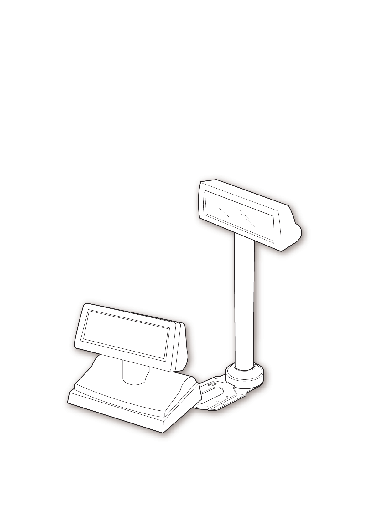
❏ The DM-D110 is a compact size, so it is possible to place on a narrow counter.
DM-D110 165mm (width) x 69mm (height) x 50.5mm (depth)
DP-110 165mm (width) x 69mm (height) x 110mm (depth)
❏ The display panel can be adjusted to the an easy to see position by moving it to the right and
left or up and down.
❏ The DM-D110 can be installed in the EPSON HSS series and TM printers by using the option
parts.
❏ The DM-D110 can be placed at a height that is easy to see by using the extension pole.
❏ The communication speed can be set to 2400bps - 115200bps in accordance with the RS-232
interface.
❏ The EPSON TM printer and the cash drawer can be connected and controlled by using one
interface. (In the case of the pass through connection and Y connection*2) The number of
interface connections of the host computer can be reduced.
❏ OPPS and APD (Windows driver) are prepared with Windows. The display using any other
OS and the connecting equipment are prepared by ESC/POS commands.
❏ There are two model colors of cool white and dark gray, and these colors are unified with
the EPSON HSS series and TM printers. It is possible to choose the one that fits to the
atmosphere of your shop.
*1 The initial setting is the brightest setting. It is adjusted by an ESC/POS command.
*2 A TM printer with a DM-D connector can be used. The cash drawer can be connected by using a TM
printer that has the DK connector.
*3 APD cannot be used in a net environment.
Rev. A General Information 1-1
Page 12
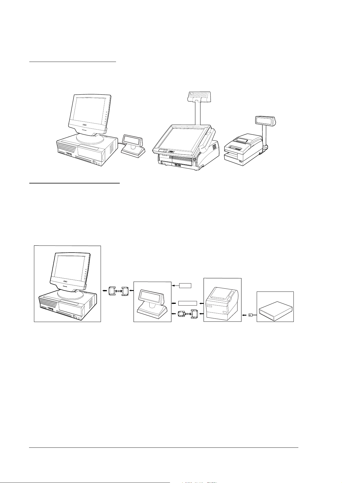
1.2 Installation Example
The DM-D110 can be attached to the EPSON HSS series and TM printers, and it can be attached
to a DM-D stand.
1.3 Connection Example
1.3.1 Pass-through Connection
The pass through connection is the way of connecting the TM printer with the cash drawer by
passing through the stand of the customer display by using one serial port of the host personal
computer.
Host PC
DM-D110 + DP-110
PS-180
TM printer
Cash Drawer
Power cable
1-2 General Information Rev. A
Page 13
DM-D110 Technical Reference Guide
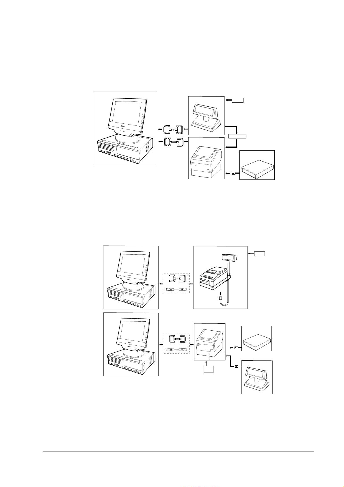
1.3.2 Stand-Alone Connection
One serial port of the host personal computer is used as the exclusive port of the customer
display.
Host PC
DM-D110 + DP-110
TM printer
PS-180
Power cable
Cash Drawer
When [Serial Port3 Mode] of the SR-610 is set [DRW/DM-D], the customer display and the cash
drawer can be controlled by COM3.
1.3.3 Y-type Connection
Y-type Connection is the way of connecting the DM-D110 with the customer display and the
cash drawer by passing through the printer from one serial/USB port of the host personal
computer.
Host PC
TM printer
DM-D110 + DP-502
PS-180
Host PC
TM printer
PS-180
AC-170
USB I/F
Cash Drawer
DM-D110 + DP-110
When [Serial Port3 Mode] of the SR-610 is set [TM/DM-D], the TM printer, the customer display
and the cash drawer can be controlled by COM3.
Rev. A General Information 1-3
Page 14

1.4 System Requirements
❏ A personal computer having a serial I/F
❏ A TM printer having a DM-D connector
❏ EPSON HSS series
1.5 System Planning
A customer display can display and be controlled using any of the following three methods:
1. ESC/POS commands
2. EPSON OPOS ADK
3. Windows printer driver (EPSON Advanced Printer Driver)
Refer to the "Application development information" in Chapter 5 from the characteristics of
each.
1-4 General Information Rev. A
Page 15

DM-D110 Technical Reference Guide
Chapter 2
Setup information
2.1 Cautions on Handling
When you use the DM-D110, be sure to note the following points:
❏ Avoid locations that are subject to high temperature and humidity.
❏ Avoid dirty and dusty locations.
❏ Avoid locations that are unstable or are subject to high levels of vibration.
❏ When connecting or disconnecting cables, make sure that the power switch of the DM-D110
and printers connected to the DM-D110 are turned off.
❏ Do not drop the DM-D110 because you may damage the built-in vacuum fluorescent
display.
2.2 Usage
The DM-D110 can be used with the following equipment.
❏ IR-320 series. You can attach the DM-D110 to the IM series using the “DM-D pole unit for
IR” (DP-504). (Refer to the IR-320 Technical Reference manual.)
❏ IR-700 series. You can attach the DM-D110 to the IR-700 the DM-D support unit (DP-506) for IR-
700 series. (Refer to the IR-700 Technical Reference guide.)
❏ SR-610 series. You can attach the DM-D110 to SR-610 series. You can attach the DM-D110 to
the SR-610 using the DM-D support unit (DP-504 ) for SR-6 10 series. (Refer to the SR-610 Te chnical
Reference guide.)
❏ DM-D stand. You can attach the DM-D110 to the DM-D stand directly using the “DM-D
stand unit for DM Customer Display” (DP-110-1x1). When using the DM-D stand, an
optional power supply unit (PS-180) is required. Also, if you want to extend the height of the
DM-D110, an optional extension support unit (DP-105) is required. (See page 2-2.)
❏ TM-H6000 series/TM-U675. You can attach the DM-D110 to TM-H6000II/TM-U675 printers
using the “DM-D pole unit for TM printers (Type A)” (DP-502). (See page 2-11.)
❏ TM-H5000 series/TM-J8000 printers. You can attach the DM-D110 to TM-H5000II/TM-
J8000 printers using the “DM-D pole unit for TM printers (Type B)” (DP-503). (See page 2-
16.)
❏ TM-U950. You can attach the DM-D110 to the TM-U950 printers using the “DM-D pole unit
for TM printers (Type A)” (DP-502). (See page 2-18.)
❏ Other TM printers. You can attach the DM-D110 using the “DM-D pole unit for TM printers
(Type A)” (DP-502) and Velcro tapes or screws. (See page 2-21.)
Rev. A Setup information 2-1
Page 16

2.3 Accessories
2.3 Accessories
2.3 Accessories2.3 Accessories
DP-110-1x1 DP-110-1x2 DP-502 DP-503 DP-504 DP-505
extension cable for power supply1- ----
RS-232C connector installation screw
(mm type)
fixing topping screw (M3 X 10) - - 2 3 - -
fixing screw (M3 X 5) --2---
fixing screws for wood position
(M3.1 X 10)
rubber feet (square) - - 4 - - -
velcro tapes set - - 1 - - 1
rubber feet (big) - - 2 - - -
fixing screw (M3 X 8) - - --3-
extension support --1---
rubber feet (small) - - 4 - - -
fixing plate ,A --1---
fixing screws for fixing plate - - 4 - - -
stopper --1---
fixing screw for stopper - - 1 - - -
DM-D angle fixing screw --1---
fixing plate ,B - - 1 - - -
4- ----
--4--5
2.4 Assembling
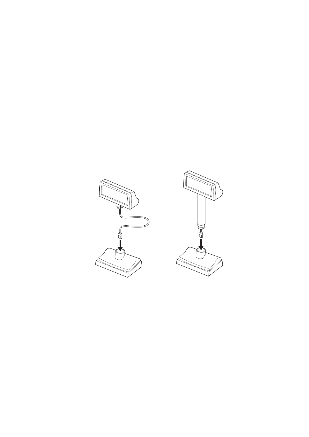
Attach the DM-D110 by usingb the following procedure.
2.4.1 Attaching to the DM-D stand
The DM-D110 can be attached directly to the DM-D stand using the “DM-D stand unit for DM
Customer Display” (DP-110). The DM-D110 with the DM-D stand can be connected to a TM
printer, or be used as a standalone product.
The function differs with the DM-D stand types.
• DP-110-101/DP-110-111 : This is connected to the personal computer and the TM
printer with the pass-through connection.
• DP-110-102/DP-110-112 : This is connected to the TM printer with the Y-type
connection and this is set on the desk for the DM-D110 and
the DP-110-1x2.
2-2 Setup information Rev. A
Page 17
DM-D110 Technical Reference Guide
>
>
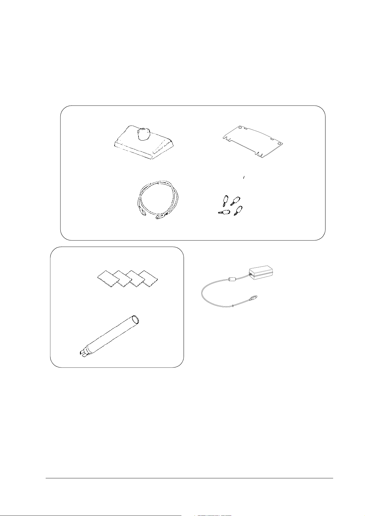
2.4.1.1 Required items
The following items are used to attach the DM-D110 to the DM-D stand. The power supply unit
(PS-180) and the extension support (DP-105) are options. For details, ask your dealer.
<DM-D stand unit for DM Customer Display (DP-110)
DM-D stand
extension cable for
power supply
<extension support (DP-105)
Velcro tapes
interface connector
base plate
RS-232C connector installation screw
(mm type)
power supply unit
(PS-180)
extension support
Rev. A Setup information 2-3
Page 18
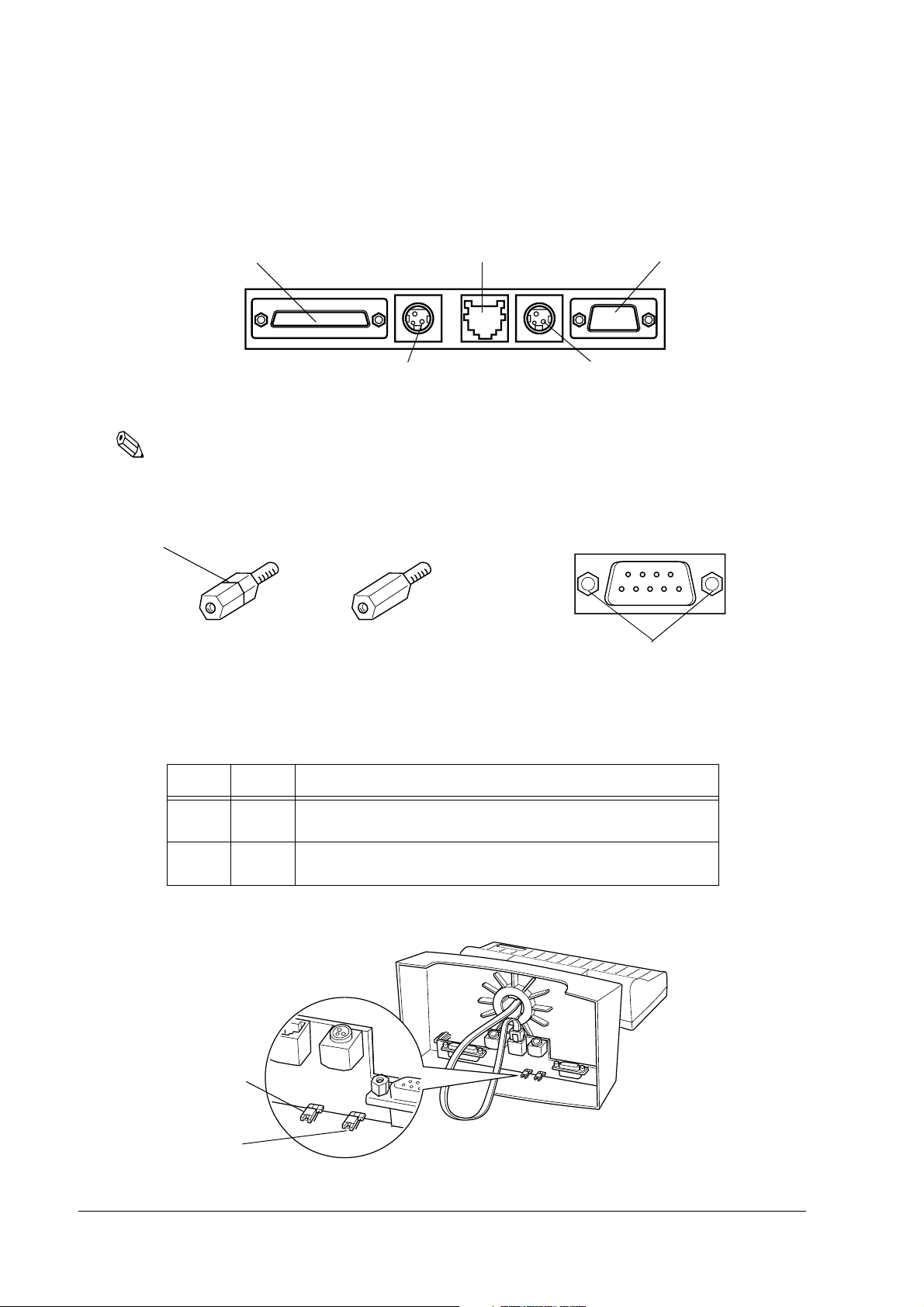
2.4.1.2 Connectors for the DP-110-1x1
The connectors for the DP-110-1x1 are as follows:
computer connector
power supply unit connector
display connector
printer connector
extension cable connector
Note:
Inch-type hexagonal lock screws are installed in the RS-232 connector. If millimeter-type lock screws are
needed, use the millimeter-type lock screws of the accessory.
notch (one or more lines)
inch-type
millimeter-type
RS-232C connector
installation screw
2.4.1.3 Jumper setting
Set the jumpers on the DM-D stand as follows:
JP1 JP2 Perpose
1-2 1-2 For connecting both the TM printer and the DM-D stand.
2-3 2-3 For using the DM-D stand a standalone.
(Default setting)
(TM printer is not connected.)
The jumpers are located as shown below:
JP1
JP2
2-4 Setup information Rev. A
Page 19
DM-D110 Technical Reference Guide
2.4.1.4 Precautions on using the power supply unit
To avoid damage to the DM-D110 and the power supply unit, make sure to note the following
points.
❏ Use the optional Seiko Epson products, PS-180 as the power supply.
❏ Never connect the DC cable to the power supply unit when the power supply unit is
connected.
❏ Unplug the DC cable by holding the connector part. If you pull the cable to unplug it, it may
be damaged.
2.4.1.5 Assembling steps
1. Pass the cable for the DM-D110 through the DM-D stand.
When extending the length of the DM-D stand, attach the extension support (DP-105) to the
DM-D stand.
When using the
extension support
(DP-105)
Rev. A Setup information 2-5
Page 20
2. Insert the tab on the DM-D110 (or the extension support) into the hole on the DM-D stand
until you feel it click.
3. When connecting to a TM printer with a Y-type connection, skip to step 13. Connect the
cable for the DM-D110 to the display connector on the DM-D stand until you feel it click.
2-6 Setup information Rev. A
Page 21

DM-D110 Technical Reference Guide
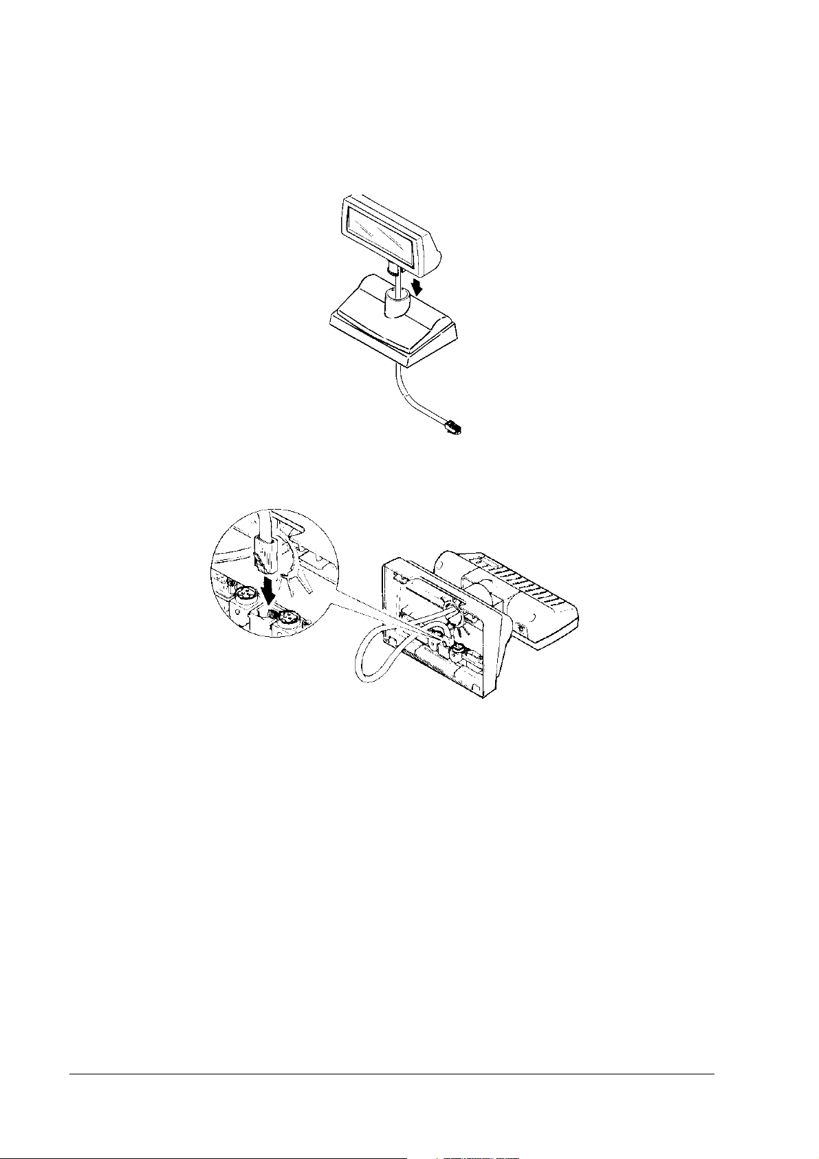
4. Connect one end of the interface cable to the computer connector inside the DM-D stand and
connect the other end to the RS-232 connector of the host personal computer. Tighten the
screws on both ends of the cables to fasten them.
computer
5. When using as a standalone, go to step 7.
When using with a printer, connect one end of the printer interface cable for the printer to
the printer connector on the DM-D stand; then connect the other end to the connector on the
printer. Tighten the screws on both ends of the cable to fasten them
.
printer
Rev. A Setup information 2-7
Page 22

6. When not using the extension cable for the power supply packed with the DM-D stand, go
e
to step 7.
When using the extension cable, connect it (with the arrow mark up) to the extension cable
connector indicated by “POWER OUT” on the DM-D stand; then connect the other end to
the power connector on the printer.
extension cabl
connector
extension cable for
power supply
7. Connect the DC cable of the power supply unit (with the arrow mark up) to the power
supply unit connector indicated by “POWER IN” on the DM-D stand.
power supply unit
connector
DC cable of power
supply unit
8. When using as a standalone product, set the jumpers. (See “Jumper setting” on page 2-4.)
2-8 Setup information Rev. A
Page 23

DM-D110 Technical Reference Guide
9. Arrange the cables as shown below. Put the cables for the DM-D110 inside the DM-D stand.
10. Attach the base plate to the DM-D stand following the numbered arrows shown below. Then
push the base plate until it is locked by the hook on the DM-D stand.
1
2
11. When the extension support (DP-105) is used, attach Velcro tapes to the four corners of the
plate to keep the unit from falling down.
12. Connect the cord of the power unit to the socket. This completes the setting.
Note:
When connecting with the pass through connection or the standalone connection, step from 13
to 16 are not needed.
13. Connect the cable of the DM-D110 to the connector of the printer.
Rev. A Setup information 2-9
Page 24

14. Set the DIP switch of the DM-D110 and switch the communication speed as follows. (Refer to
Chapter 3 doe details of the DIP switch setting.)
Communication speed: 19200bps
Communication data length: 8Bit
Parity: Off
15. Attach the base plate to the DM-D stand following the numbered arrows shown below. Then
push the base plate until it is locked by the hook on the DM-D stand.
1
2
16. When the extension support (DP-105) is used, attach Velcro tapes to the four corners of the
plate to keep the unit from falling down. This completes the setting.
2-10 Setup information Rev. A
Page 25

DM-D110 Technical Reference Guide
2.4.2 Attaching to the TM-H6000 Series/TM-U675
The DM-D110 can be attached directly to the TM-H6000II/TM-U675 printers using the “DM-D
pole unit for TM printers (Type A)” (DP-502). You can attach fixing plate A on either side of the
TM-H6000II/TM-U675. After attaching it, you can slide the display freely.
2.4.2.1 Required items
The following items are used to attach the DM-D110 to the TM-H6000II/TM-U675 printers.
These items are packed with the “DM-D pole unit for TM printers (Type A)” (DP-502).
stopper
fixing screws for
rubber feet (small)
support C
fixing screw
for stopper
rubber feet (small)
support B
for extension
angle fixing
screw
fixing plate B
fixing screws for
fixing plate B
fixing plate A
Rev. A Setup information 2-11
Page 26

2.4.2.2 Assembling steps
1. Pass the cable for the DM-D110 through support C, and attach support C to the DM-D110.
When using support B for extension, insert the tab on support B into the hole on support C
until you feel it click.
When using support B for
extension
2. Attach the rubber feet to the printer.
3. Attach fixing plate B to the printer.
2-12 Setup information Rev. A
Page 27

DM-D110 Technical Reference Guide
4. Pass the cable for the DM-D110 through the hole on fixing plate A, and fix the cable at the
bottom as shown below.
5. Connect the cable for the DM-D110 to the DM connector on the TM printer.
6. Attach fixing plate A to the TM printer using the stopper. When you attach the stopper,
insert the projections on the stopper into the holes of fixing plate B. Fixing plate A can be
attached on either side of the printer. (The illustration below shows fixing plate A attached
to the right side of the printer.)
Rev. A Setup information 2-13
Page 28

7. The horizontal rotation mechanism of fixing plate A can be adjusted. To secure the location
of the display, set fixing plate A to either one of the following four positions and secure it
with the angle fixing screw.
2-14 Setup information Rev. A
Page 29

DM-D110 Technical Reference Guide
Note:
The paper roll cover may not open if the position of the display is incorrect. Before securing the
position of the display, make sure that you can open the paper roll cover.
paper roll cover
8. Store any excess cable in the support and attach the DM-D110 to fixing plate A.
9. Connect the power cable of the printer. To avoid disconnection, hook the cable on the tabs
on fixing plate B, as shown below.
Rev. A Setup information 2-15
Page 30

2.4.3 Attaching to the TM-H5000 Series/TM-J8000
The DM-D110 can be attached directly to the TM-H5000II/TM-J8000 printers using the “DM-D
pole unit for TM printers (Type B)” (DP-503).
2.4.3.1 Required items
The following items are used to attach the DM-D110 to the TM-H5000II /TM-J8000 printers.
These items are packed with the “DM-D pole unit for TM printers (Type B)” (DP-503).
fixing screws
base
support A
support B
(for extension)
2.4.3.2 Assembling steps
1. Pass the cable for the DM-D110 through support C and attach support C to the DM-D110.
When using support B for extension, insert the tab on support B into the hole on support C
until you feel it click.
When using support B for
extension
2-16 Setup information Rev. A
Page 31

DM-D110 Technical Reference Guide
2. Attach the base to the setting position on the TM printer and secure it with the screws.
3. Pass the cable for the DM-D110 through the base.
4. Insert the tab on the base into the hole on the support until you feel it click.
5. Connect the cable for the DM-D110 to the DM connector on the TM printer.
Rev. A Setup information 2-17
Page 32

2.4.4 Attaching to the TM-U950
fixi
The DM-D110 can be attached directly to the TM-U375/TM-U950 printers using the “DM-D
pole unit for TM printers (Type A)” (DP-502).
2.4.4.1 Required items
The following items are used to attach the DM-D110 to the TM-U375/TM-U950 printers. These
items are packed with the “DM-D pole unit for TM printers (Type A)” (DP-502).
<For TM-U950>
rubber feet
(square)
ng screws
for plastic position
support C
<For TM-U375 and TM-U950>
support B
for extension
fixing plate A
2-18 Setup information Rev. A
Page 33

DM-D110 Technical Reference Guide
2.4.4.2 Assembling steps
1. Pass the cable for the DM-D110 through support C and attach support C to the DM-D110.
When using support B for extension, insert the tab on support B into the hole on support C
until you feel it click.
2. Attach the rubber feet to the printer.
When using support B for
extension
[TM-U950]
Rev. A Setup information 2-19
Page 34

3. Pass the cable for the DM-D110 through the hole on fixing plate A and fix the cable at the
bottom as shown below.
4. Connect the cable for the DM-D110 to the DM connector on the TM printer.
5. Adjust the length of the cable and secure fixing plate A to the printer with screws.
[TM-U950]
2-20 Setup information Rev. A
Page 35

DM-D110 Technical Reference Guide
6. Store any excess cable in the support, and attach the DM-D110 to fixing plate A.
2.4.5 Attaching to Other TM Printers
When using with other TM printers, the DM-D110 can be attached to a desk or other surface,
using the “DM-D pole unit for TM printers (Type A)” (DP-502), and Velcro tapes or screws.
2.4.5.1 Required items
The following items are used when the DM-D110 is used with other TM printers. These items
are packed with the “DM-D pole unit for TM printers (Type A)” (DP-502).
fixing plate A
fixing screws for
wood position
Velcro tapes
support C
Velcro tapes
support B (for extension)
Rev. A Setup information 2-21
Page 36

2.4.5.2 Assembling steps using Velcro tapes
1. Attach Velcro tapes to the bottom of fixing plate A.
2. Pass the cable for the DM-D110 through support C and attach support C to the DM-
D110.
When using support B for extension, insert the tab on support B into the hole on support
C until you feel it click.
When using support B for
extension
2-22 Setup information Rev. A
Page 37

DM-D110 Technical Reference Guide
3. Pass the cable for the DM-D110 through the hole on fixing plate A, and fix the cable at
the bottom as shown below.
4. Connect the cable for the DM-D110 to the DC connector on the TM printer.
5. Store any excess cable in the support, and attach the DM-D110 to fixing plate A.
6. Peel off the Velcro tapes and attach the display as shown above..
Rev. A Setup information 2-23
Page 38

2.4.5.3 Assembling steps using screws
1. Follow steps 2 and 3 in “Assembling steps using Velcro tapes.”
2. Secure fixing plate A to the setting position with fixing screws.
3. Attach the DM-D110 to fixing plate A.
2-24 Setup information Rev. A
Page 39

DM-D110 Technical Reference Guide
Chapter 3
DIP Switches
The DIP switches configure the communication settings and whether a self-test is required.
3.1 DIP Switches
Two DIP switches are located on the back of the display panel. The following table shows the
functions of each switch.
Functions: Refer to the tables below. The DIP switch settings are read only when the power is
turned on. Therefore, changing the settings while the power is on has no effect.
DSW1 No. Function ON OFF
1-1 Received Error Data Ignore “?” Display OFF
1-2 Receive Data Length 7bit 8bit OFF
1-3 Parity With Parity No Parity OFF
1-4 Parity Selection Even Odd OFF
1-5 Communication
Speed Switching
1-6 OFF
1-7 ON
1-8 Execute Self-Test (*1) Yes No OFF
(*1) Executes the self-test once only when the power is turned on.
Refer to “Transfer Speed
Switching”
Default
Setting
ON
3.1.1 Transfer Speed Switching
Transfer Speed
SW1-5 SW1-6 SW1-7
ON ON ON 2400
OFF ON ON 4800
ON OFF ON 9600*1
OFF OFF ON 19200*2
ON ON OFF 38400
OFF ON OFF 57600
ON OFF OFF 115200
OFF OFF OFF (Reserved)
(bps)
*1 Default Setting
*2 Setting that is used when connecting to a USB model of an EPSON TM printer.
Rev. A DIP Switches 3-1
Page 40

3.1.2 Setting the DIP switches
CAUTION:
Remove the cable of the DM-D110 before removing the DIP switch cover to prevent
electrical damage to the DM-D110.
1. Remove the cable of the DM-D110.
2. Remove the DIP switch cover.
ON
7
3
1
2
DIP switch cover
8
4
5
6
3. Change each setting of the switches with a pointed object, such as a pen tip or small
screwdriver.
Close the cover and connect the cable to computer.
3-2 DIP Switches Rev. A
Page 41

Chapter 4
Hardware
4.1 Interface Signal Connection Diagram
The illustration below shows the signal connections of the interface:
DM-D110 Technical Reference Guide
DP-110-1x1
Rev. A Hardware 4-1
Page 42

4.2 Data Flow
4.2.1 Pass-through Connection
With the pass-through connection, the command from one serial port of the host personal
computer is transmitted through the DM-D stand to control the DM-D110, the printer and the
drawer. The data flow which is connected through the DM-D stand is as follows.
DM-D stand
Host PC
DM-D110
(Display)
Transmit data from the host PC
Printer
Power supply
Transmit data to the printer
Transmit data to the host PC from
the printer
❏ With the pass-through connection, the data from the host personal computer is stored in the
reception buffer of the display, and then the data is processed sequentially and only data for
the printer is transmitted to the printer. The data transmitted from the printer is transmitted
to the host personal computer directly without passing the display.
❏ The peripheral equipment elective command distinguishes between the data for the DM-
D110 and the data for the printer.
❏ The communications condition of the host personal computer, the printer, and the DM-D110
are set to the same condition.
4-2 Hardware Rev. A
Page 43

DM-D110 Technical Reference Guide
4.2.2 Standalone Connection
With the standalone connection, the command from the serial port of the host personal
computer is transmitted directly to control the DM-D110. The data flow when the standalone
connection is as follows.
DM-D stand
Host PC
DM-D110
(Display)
Transmit data from the host PC
Transmit data to the host PC
Power supply
❏ When 1-2 of JP1 and JP2 are selected, the data from the host personal computer is
transmitted to the DM-D110 and the data from the DM-D110 is transmitted to the host
personal computer with the standalone connection.
❏ The standalone connection is effective only when the DM-D110 is selected and the user
setting commands is used.
❏ The communications condition of the host personal computer and the DM-D110 are set to
the same condition.
Rev. A Hardware 4-3
Page 44

4.2.3 Y-type Connection
With the Y-type connection, the command from the serial/USB port of the host personal
computer is transmitted through the printer to control the DM-D110 and the cash drawer.
The data flow when the DM-D110 is connected with the Y-type connection is as follows.
Host PC
Printer
Power supply
Transmit data from the host PC
Transmit data to the printer
Transmit data to the host PC from
the printer
DM-D110
(Display)
❏ The data from the host personal computer is transmitted to the printer and the same data is transmitted
to the DM-D110 with the stand-alone connection
❏ The peripheral equipment command of ESC/POS distinguishes between the data for the
DM-D110 and the data for the printer.
❏ Set the communication condition of the DM-D110 as follows.
Communication speed: 19200bps
Communication data length: 8Bit
Parity: Off
4-4 Hardware Rev. A
Page 45

DM-D110 Technical Reference Guide
4.2.4 DM-D110 Standard Model Interface Connectors
Type: RJ-45 Connector
4.2.4.1 Display interface connector pin assignments
Display interface connector pin assignments
Pin
Number
1FG —
2TXDOutput
3RXDInput
4DSRInput
5DTROutput
6SG —
7PS —
8PG—
(*1) For a Y-type, pass-through, and standalone connection, refer to the “Connection type” paragraph for details.
(*2) [DTR MARK] can be set by the US v command. This case differs from the above-mentioned [DTR MARK].
Signal
Name
Signal
Direction
Signal Function
Frame ground
(1) When the DM-D110 is connected with a pass-through or Y-type
connection: Transmits data to the printer.
(2) When the DM-D110 is connected as a standalone: Transmits data to the
host.
Receives data from the host.
Indicates whether the host is ready to receive data.
(1) When the DM-D110 is connected with a Y-type connection (*1) : Unused
(2) When the DM-D110 is connected with a pass-through (*2) :
MARK: The printer is not ready to receive data
SPACE: The printer is ready to receive data.
(3) When the DM-D110 is connected as a standalone:
MARK: The host is not ready to receive data.
SPACE: The host is ready to receive data.
This indicates whether the display is ready to receive data (*2).
MARK: The display is not ready to receive data.
DTR goes to MARK under the following conditions.
(1) The period from when the power is turned on until the display becomes
ready to receive data.
(2) When the self-test is executed.
(3) When the remaining space in the receive buffer becomes 40 bytes or
less.
(4) When MARK is on, if the printer is selected by a peripheral device.
SPACE: The display is ready to receive data.
DTR goes to SPACE under the following conditions.
(1) When the display first becomes ready to receive data after power-on.
(2) When the self-test has ended.
(3) When the remaining space in the receive buffer becomes 50 bytes or
more after it becomes 40 bytes or less.
Signal GND
Power supply terminal
Return wire for power
Rev. A Hardware 4-5
Page 46

4.3 DM-D110 and PC Connection Cable
The host interface connector connects the host computer to the DM-D110 standard model via the
DM-D stand.
Type: D-SUB 25-pin connector (female type)
The optional stand provides the host interface connector shown in the figure below.
4.3.0.1 Host interface connector pin assignments
Host interface connector pin assignments
Pin
Number
1FG— Frame ground
2 TXD Output 1) When the DM-D110 is connected with a pass-through or Y-type
3 RXD Input Receives data from the host (host —> DM)
4 (*1) RTS Input Same as DTR
6 (*2) DSR Input Indicates whether the host is ready to receive data.
7GND— Signal ground
20 (*1) DTR Output This indicates whether the display is ready to receive data (*2).
25 RESET Input Reset signal is connected to the DTR terminal of the printer directly.
NOTES: (*1): Make sure to use either the RTS or the DTR terminal. Otherwise, the built-in RS-232 driver IC
Signal
Name
may be broken.
(*2): This signal is connected to the DTR terminal of the printer directly.
Signal
Direction
Function
connection, transmits data to the host from the printer.
2) When the DM-D110 is connected as a standalone: transmits data to
the host from the DM
SPACE The host is ready to receive data.
MARK The host is not ready to receive data.
SPACE The display can receive data.
MARK The display cannot receive data.
DTR MARK
DTR goes to MARK under the following conditions:
1) The period from when power is turned on to when the display first
becomes ready to receive data.
2) When the self-test is executed.
3) When the remaining space in the receive buffer becomes 128 bytes
or less (buffer-full state).
4) When DSR MARK is on, if the printer is selected by a peripheral device
command.
DTR SPACE
DTR goes to SPACE under the following conditions:
1) When the display first becomes ready to receive data after power-
on.
2) When the self-test has ended.
3) When the remaining space in the receive buffer becomes 50 bytes
or more after having been 40 bytes or less.
4-6 Hardware Rev. A
Page 47

DM-D110 Technical Reference Guide
4.3.1 DP-110 Printer Interface Connector
The printer interface connector connects a standard model DM-D110 to the printer via the DM-D
stand.
Type: D-SUB 9-pin connector (male type)
The optional stand provides the printer interface connector shown in the figure below.
4.3.1.1 Printer interface connector pin assignments
Table 1-1 Printer interface connector pin assignments
Pin
Number
2 RXD Input Receive data from the printer (printer to host)
3 TXD Output Transmit data to the printer (DM to printer)
4 DTR Output Indicates whether the host is ready to receive data.
5GND— Signal GND
6 DSR Input This indicates whether the display is ready to receive data from the printer.
9 RESET Output Reset signal to the printer (host to printer)
Signal
Name
Signal
Direction
Function
SPACE The printer is ready to receive data.
MARK The printer is not ready to receive data.
SPACE The printer can receive data. When the printer becomes ready to
receive data SPACE is output.
MARK The printer cannot receive data. If the printer becomes ready to
receive data, MARK is not output.
Rev. A Hardware 4-7
Page 48

4.3.2 DP-110 Power Supply Connector
The base unit of the DM-D stand provides two power supply connectors. One is used for the
input terminals from the external power supply and the other is used to supply power to the
printer. Both connectors have the same electrical characteristics (signal functions, signal
direction, signal level). These connectors can be used for the DM-D110 power supply connector
to the display interface board or the power supply connector to the printer.
Type: 3-pin locking type connector.
4.3.2.1 Power supply connector pin assignments
Power supply connector pin assignments
Pin Number Signal Name Signal Direction Signal Function
1 +24V — Power supply line
2GND— GND
3NC— Unused
SHELL FG — Frame GND
4-8 Hardware Rev. A
Page 49

DM-D110 Technical Reference Guide
Chapter 5
Application Development Information
This chapter describes how to control the customer display.
5.1 Introducing the Control Methods
5.1.1
5.1.1 Commands
5.1.1 5.1.1
Commands
CommandsCommands
❏ ESC/POS commands
ESC/POS commands directly control the customer display and control all the functions of it.
However, detailed knowledge of the hardware, control, and operating environment is required
and you need to code all the functions for yourself.
To use ESC/POS commands, “Nondisclosure agreement” and “User registration” are required.
Please contact us to use ESC/POS.
5.1.1.1 Operating environment
5.1.1.1 Operating environment
5.1.1.1 Operating environment5.1.1.1 Operating environment
Environment in which you can use ESC/POS commands. (For example, MS-DOS.)
5.1.2
5.1.2 Driver
5.1.2 5.1.2
5.1.3
5.1.3 Features of
5.1.3 5.1.3
5.1.3.1
5.1.3.1 Using OPOS
5.1.3.1 5.1.3.1
Driver
DriverDriver
The following drivers are provided to control the customer display.
❏ EPSON OPOS ADK (Recommended)
❏ Windows Printer Driver (EPSON Advanced Printer Driver)
Features of EPSON OPOS ADK
Features of Features of
The OPOS driver is a standard of the OCX control driver for POS peripherals. Controlling the
POS peripherals including the customer display with original commands from an application is
not required, and it enables efficient system development reducing development steps.
Using OPOS
Using OPOSUsing OPOS
The following is required to use OPOS.
❏ OPOS driver and manuals provided by EPSON
(Download from our homepage.)
EPSON OPOS ADK
EPSON OPOS ADKEPSON OPOS ADK
❏ Application Programmer's Guide issued by Open POS Technology Council
Rev. A Application Development Information
Application Development Information 5-1
Application Development InformationApplication Development Information
Page 50

5.1.3.2 Operating environment
5.1.3.2 Operating environment
5.1.3.2 Operating environment5.1.3.2 Operating environment
❏ Supported OS (Operation checked)
• Windows2000 Professional SP4 or later
• Windows XP Professional SP2 or later
See OPOS release notes for the latest information.
❏ Supported development language
• Visual Basic
• VisualC++
5.1.4
5.1.4 Features of
5.1.4 5.1.4
Features of Windows
Features of Features of
EPSON Advanced Printer Driver is a Windows driver for the display function of the customer
display. You can display on the customer display without programing any applications as well
as a standard Windows printer driver.
You cannot display on the customer display in a .net environment. In an environment other than
.net, you can display only the exclusive fonts for the customer display. (You cannot display
TrueType fonts, Kanji, Hiragana, and Katakana.)
Windows Driver (
WindowsWindows
Driver (EPSON Advanced Printer Driver
Driver ( Driver (
EPSON Advanced Printer Driver))))
EPSON Advanced Printer DriverEPSON Advanced Printer Driver
As the APD for the customer display, a package for use in a standalone environment and a
package for use with the same port as the TM printer are provided.
APD and manuals provided by EPSON are required to use the APD. Download them from our
homepage.
5.1.4.1
5.1.4.1 Operating environment
5.1.4.1 5.1.4.1
Operating environment
Operating environmentOperating environment
❏ Supported OS (Operation confirmed by EPSON)
• Windows2000 Professional SP4 or later
• Windows XP Professional SP2 or later
See the release note for the driver for the latest information.
❏ Supported development language
• Visual Basic
• VisualC++
5-2 Application Development Information
Application Development Information Rev. A
Application Development InformationApplication Development Information
Page 51

DM-D110 Technical Reference Guide
5.2 Selecting Environment and Driver
Select the driver for the customer display depending on your environment.
Environment other than .net
Windows environment .net environment
When you develop a new
application.
When you already use
OPOS with an existing
application.
When you already use the
APD with an existing
application.
(The APD and OPOS cannot
both be in one PC. Use
Use OPOS. OPOS is recommended.
(You can also use the APD,
but OPOS is recommended
Use OPOS. Use OPOS.
Use OPOS.
OPOS also for the TM
printer.)
(Embedded fonts in the
customer display are
available.)
for system extensibility.)
Use the APD.
Rev. A Application Development Information
Application Development Information 5-3
Application Development InformationApplication Development Information
Page 52

5-4 Application Development Information
Application Development Information Rev. A
Application Development InformationApplication Development Information
Page 53

Appendix A
Character Code Tables
A.1 Page 0 (PC437: U.S.A., standard Europe)
(international character set: U.S.A.)
DM-D110 Technical Reference Guide
Page 0 Indicated characters (00H-7FH)
Note 1: Character codes from 00H (hexadecimal) to 7FH (hexadecimal) for each page are the same.
Note 2: Some characters indicated by character codes from 00H to 7FH are changed by selecting the
international character set. Refer to Section 4.3.13, Intern ational character set, for details.
Rev. A Character Code Tables
Character Code Tables Appendix A-1
Character Code TablesCharacter Code Tables
Page 54

Page 0 Indicated Characters (80H?FFH)
Appendix A-2 Character Code Tables
Character Code Tables Rev. A
Character Code TablesCharacter Code Tables
Page 55

A.2 Page 1 (Katakana)
DM-D110 Technical Reference Guide
Page 1 Indicated Characters (80H-FFH)
Rev. A Character Code Tables
Character Code Tables Appendix A-3
Character Code TablesCharacter Code Tables
Page 56

A.3 Page 2 (PC850: multilingual)
Page 2 Indicated Characters (80H-FFH)
Appendix A-4 Character Code Tables
Character Code Tables Rev. A
Character Code TablesCharacter Code Tables
Page 57

A.4 Page 3 (PC860: Portuguese)
DM-D110 Technical Reference Guide
Page 3 Indicated Characters (80H-FFH)
Rev. A Character Code Tables
Character Code Tables Appendix A-5
Character Code TablesCharacter Code Tables
Page 58

A.5 Page 4 (PC863: Canadian-French)
Page 4 Indicated Characters (80H-FFH)
Appendix A-6 Character Code Tables
Character Code Tables Rev. A
Character Code TablesCharacter Code Tables
Page 59

A.6 Page 5 (PC865: Nordic)
DM-D110 Technical Reference Guide
Page 5 Indicated Characters (80H-FFH)
Rev. A Character Code Tables
Character Code Tables Appendix A-7
Character Code TablesCharacter Code Tables
Page 60

A.7 Page 16 (WPC1252)
Page16 Indicated Characters (80H-FFH)
Appendix A-8 Character Code Tables
Character Code Tables Rev. A
Character Code TablesCharacter Code Tables
Page 61

A.8 Page 17 (PC866: Cyrillic2)
DM-D110 Technical Reference Guide
Page17 Indicated Characters (80H-FFH)
Rev. A Character Code Tables
Character Code Tables Appendix A-9
Character Code TablesCharacter Code Tables
Page 62

A.9 Page 18 (PC852: Latin2)
Page18 Indicated Characters (80H-FFH)
Appendix A-10 Character Code Tables
Character Code Tables Rev. A
Character Code TablesCharacter Code Tables
Page 63

A.10 Page19 (PC858: Euro)
DM-D110 Technical Reference Guide
Page19 Indicated Characters (80H-FFH)
Rev. A Character Code Tables
Character Code Tables Appendix A-11
Character Code TablesCharacter Code Tables
Page 64

A.11 Page254 (Space)
Page254 Indicated Characters (80H-FFH)
Appendix A-12 Character Code Tables
Character Code Tables Rev. A
Character Code TablesCharacter Code Tables
Page 65

A.12 Page255 (Space)
DM-D110 Technical Reference Guide
Page255 Indicated Characters (80H-FFH)
UD: undefined
Rev. A Character Code Tables
Character Code Tables Appendix A-13
Character Code TablesCharacter Code Tables
Page 66

A.13 International character set
International characters listed in Table 4.3.14 can be changed by using the ESC R command. Refer to the
description of the ESC R command in Section 5.3, Command Details.
ASCII code (Hex)
Country
U.S.A # $ @ [ ¥ ] ^ ` { | } ~
France # $ à ° ç § ^ ` é ù è ¨
Germany # $ § Ä Ö Ü ^ ` ä ö ü ß
U.K. £ $ @ [ ¥ ] ^ ` { | } ~
Denmark I # $ @ Æ Ø Å ^ ` æ ø å ~
Sweden # ¤ É Ä Ö Å Ü é ä ö å ü
Italy # $ @ ° ¥ é ^ ù à ò è ì
Spain I Pt $ @ ¡ Ñ ¿ ^ ` ¨ ñ } ~
Japan # $ @ [ ¥ ] ^ ` { | } ~
Norway # ¤ É Æ Ø Å Ü é æ ø å ü
Denmark II # $ É Æ Ø Å Ü é æ ø å ü
Spain II # $ á ¡ Ñ ¿ é ` í ñ ó ú
Latin America # $ á ¡ Ñ ¿ é ü í ñ ó ú
Korea # $ @ [
23 24 40 5B 5C 5D 5E 60 7B 7C 7D 7E
W
] ^ ` { | } ~
International Character Set (Indicated Character Selection by Command)
Appendix A-14 Character Code Tables
Character Code Tables Rev. A
Character Code TablesCharacter Code Tables
 Loading...