

Epson DM-D110, DM-D210 Technical Reference Guide
Technical Reference Guide
Describes features and general specications for this
product.
Describes how to install and set this product.
Describes the basic usage of this product.
Describes how to control this product and information
necessary for developing applications.
Describes the specications of the product, connectors,
and serial cables, as well as the character code table.
Product Overview
Setup
Handling
Application Development Information
Appendix
M00035604
Rev. E

Cautions
• No part of this document may be reproduced, stored in a retrieval system, or transmitted in any form or by
any means, electronic, mechanical, photocopying, recording, or otherwise, without the prior written permission of Seiko Epson Corporation.
• The contents of this document are subject to change without notice. Please contact us for the latest information.
• While every precaution has been taken in the preparation of this document, Seiko Epson Corporation
assumes no responsibility for errors or omissions.
• Neither is any liability assumed for damages resulting from the use of the information contained herein.
• Neither Seiko Epson Corporation nor its affiliates shall be liable to the purchaser of this product or third par-
ties for damages, losses, costs, or expenses incurred by the purchaser or third parties as a result of: accident,
misuse, or abuse of this product or unauthorized modifications, repairs, or alterations to this product, or
(excluding the U.S.) failure to strictly comply with Seiko Epson Corporation’s operating and maintenance
instructions.
• Seiko Epson Corporation shall not be liable against any damages or problems arising from the use of any
options or any consumable products other than those specified as Original Epson Products or Epson
Approved Products by Seiko Epson Corporation.
Trademarks
EPSON is a registered trademark of Seiko Epson Corporation.
Exceed Your Vision and ESC/POS are registered trademarks or trademarks of Seiko Epson Corporation.
Microsoft® and Windows® are either registered trademarks of Microsoft Corporation in the United States and
o
ther countries.
IOS® is a trademark or registered trademark of Cisco in the U.S. and other countries and is used under license.
And
All other trademarks are the property of their respective owners and used for identification purpose only.
TM
roid
is a trademark of Google LLC.
ESC/POS® Proprietary Command System
Epson took the initiative by introducing ESC/POS, a proprietary POS printer command system, which includes
patented or patent pending commands and enables versatile POS system construction with high scalability.
Compatible with all types of Epson POS printers and displays, this proprietary control system also offers the
flexibility to easily make future upgrades. Its popularity is worldwide.
ESC/POS is designed to reduce the processing load on the host computer in POS environments. It comprises a
set of highly functional and efficient commands that enables the full realization of the potential of printers.
©Seiko Epson Corporation 2006-2019. All rights reserved.
2
For Safety
Key to Symbols
The symbols in this manual are identified by their level of importance, as defined below. Read the following
carefully before handling the product.
Yo u must follow warnings carefully to avoid serious bodily injury.
WARNING
Provides information that must be observed to prevent damage to the equipment or loss of data.
• Possibility of sustaining physical injuries.
CAUTION
• Possibility of causing physical damage.
• Possibility of causing information loss.
Provides information that must be observed to avoid damage to your equipm ent or a
malfunction.
Provides important information and useful tips.
3

Warnings
WARNING
• To avoid risk of electric shock, do not set up this product or handle cables during a thunderstorm.
• Never insert or disconnect the power plug with wet hands.
Doing so may result in severe shock.
• Handle the power cable with care.
Improper handling may lead to fire or electric shock.
∗ Do not modify or attempt to repair the cable.
∗ Do not place any heavy object on top of the cable.
∗ Avoid excessive bending, twisting, and pulling.
∗ Do not place the cable near heating equipment.
∗ Check that the plug is clean before plugging it in.
∗ Be sure to push the plug all the way in.
• Be sure to use the specified power source.
Connection to an improper power source may cause fire or shock.
• Do not place multiple loads on the power outlet.
Overloading the outlet may lead to fire or shock.
• Shut down your equipment immediately if it produces smoke, a strange odor, or unusual
noise.
Continued use may lead to fire. Immediately unplug the equipment and contact qualified service personnel for advice.
• Never attempt to repair this product yourself.
Improper repair work can be dangerous.
• Never disassemble or modify this product.
Tampering with this product ma
• Do not allow foreign matter to fall into the equipment.
Penetration by foreign objects may lead to fire.
• If water or other liquid spills into this equipment, do not continue to use it.
Continued use may lead to fire. Unplug the power cord immediately and contact qualified service personnel for advice.
• Do not use aerosol sprayers containing flammable gas inside or around this product.
Doing so may cause fire.
• Do not connect cables in ways other than those mentioned in this manual.
Different connections may cause equipment damage or fire.
• Do not use this product in locations subject to high humidity or dust levels.
Excessive humidity and dust may cause equipment damage or fire.
y r
esult in injury or fire.
Cautions
CAUTION
• Be sure to set this equipment on a firm, stable, horizontal surface.
The product may break or cause injury if it falls.
• Do not place heavy objects on top of this product. Never stand or lean on this product.
Equipment may fall or collapse, causing breakage and possible injury.
• To ensure safety, unplug this product before leaving it unused for an extended period.
• Do not drop the this product because you may damage the built-in vacuum fluorescent
display.
• Using in the presence of silicon gas (silicon adhesive, silicon oil, silicon powder, etc.)
including siloxane and of malignant gas (nitric acid, hydrosulfuric, ammonia, chlorine,
etc.) may cause contact failure at contact points in a mechanical switch, etc., in a short
time because of adhesion or oxidization of the insulation film.
4

Restriction of Use
When this product is used for applications requiring high reliability/safety, such as transportation devices
related to aviation, rail, marine, automotive, etc.; disaster prevention devices; various safety devices, etc.; or
functional/precision devices, etc., you should use this product only after giving consideration to including failsafes and redundancies into your design to maintain safety and total system reliability. Because this product was
not intended for use in applications requiring extremely high reliability/safety, such as aerospace equipment,
main communication equipment, nuclear power control equipment, or medical equipment related to direct
medical care, etc., please make your own judgment on this product's suitability after a full evaluation.
About this Manual
Aim of the Manual
This manual provides the development engineers with necessary information for developing, designing, installing the system using DM-D110/DM-D210 as well as for developing and designing the applications.
Manual Content
The manual is made up of the following sections:
Chapter 1 Product Overview
Chapter 2 Setup
Chapter 3 Handling
Chapter 4 Application Development
Appendix Product Specifications
-110/DP-210 Connector Specifications
DP
Serial Cable Specifications
Character Code Tables
Information
5

Contents
■ For Safety..................................................................................................................................3
Key to Symbols.................................................................................................................................................................... 3
Warnings ............................................................................................................................................................................... 4
Cautions................................................................................................................................................................................. 4
■ Restriction of Use ....................................................................................................................5
■ About this Manual ..................................................................................................................5
Aim of the Manual ............................................................................................................................................................. 5
Manual Content .................................................................................................................................................................. 5
■ Contents....................................................................................................................................6
Product Overview ............................................................................................9
■ Features ....................................................................................................................................9
■ Product Structure................................................................................................................. 10
Customer Display .............................................................................................................................................................10
Accessories .........................................................................................................................................................................10
Options ................................................................................................................................................................................11
■ Part Names ............................................................................................................................ 12
DM-D110 .............................................................................................................................................................................12
DP-110..................................................................................................................................................................................12
DM-D110 for TM-T88V-DT/TM-T88VI-DT2 ...............................................................................................................13
DM-D210 .............................................................................................................................................................................14
DP-210..................................................................................................................................................................................14
■ System Outline ..................................................................................................................... 15
USB (Self Powered) ..........................................................................................................................................................15
USB (Bus Powered): Computer ....................................................................................................................................15
USB (Bus Powered): TM Intelligent Printer ..............................................................................................................16
Serial (Stand-Alone).........................................................................................................................................................17
Serial (Pass-through) .......................................................................................................................................................17
Serial (Y-type) ....................................................................................................................................................................18
Serial (USB controlled)....................................................................................................................................................19
Serial (USB/Ethernet controlled).................................................................................................................................19
Connection patterns by options.................................................................................................................................20
6

Setup ...............................................................................................................21
■ Setup Flow............................................................................................................................. 21
USB (Self Powered) ..........................................................................................................................................................21
USB (Bus Powered): Computer ....................................................................................................................................22
USB (Bus Powered): TM Intelligent Printer ..............................................................................................................22
Serial (Stand-Alone).........................................................................................................................................................23
Serial (Pass-through) .......................................................................................................................................................23
Serial (Y-type) ....................................................................................................................................................................24
Serial (USB controlled)....................................................................................................................................................25
Serial (USB/Ethernet controlled).................................................................................................................................26
■ Dip Switch Settings.............................................................................................................. 27
Settings by connection patterns ................................................................................................................................27
Setting method.................................................................................................................................................................28
DIP Switch 1 Functions...................................................................................................................................................29
■ Attaching the Product......................................................................................................... 30
DP-110..................................................................................................................................................................................31
DP-210..................................................................................................................................................................................35
DP-502 (TM-H6000V) ......................................................................................................................................................38
DP-502 (TM-H6000IV/TM-U675) .................................................................................................................................44
DP-502 (TM-H6000IV-DT)..............................................................................................................................................50
DP-502 (TM-U950) ...........................................................................................................................................................56
DP-502 (TM-J7200 / TM-J7700) ...................................................................................................................................59
DP-502 (Attaching on the counter) ...........................................................................................................................63
DP-503 (TM-H5000II).......................................................................................................................................................66
DM-D110 for TM-T88V-DT/TM-T88VI-DT2 ...............................................................................................................68
■ Connecting............................................................................................................................ 74
USB (Self Powered) ..........................................................................................................................................................74
USB (Bus Powered)...........................................................................................................................................................75
Serial (Stand-Alone).........................................................................................................................................................76
Serial (Pass-through) .......................................................................................................................................................77
Serial (Y-type) ....................................................................................................................................................................78
Serial (USB controlled)....................................................................................................................................................79
Serial (USB/Ethernet controlled).................................................................................................................................80
7

Handling .........................................................................................................81
■ Changing the Orientation of the Display Unit................................................................ 81
■ Cleaning the customer display.......................................................................................... 82
Application Development Information.......................................................83
■ Controlling the Customer display..................................................................................... 83
ePOS-Device XML.............................................................................................................................................................83
ePOS-Print XML.................................................................................................................................................................84
ESC/POS...............................................................................................................................................................................84
■ Software and Manuals ........................................................................................................ 85
Development Kits ............................................................................................................................................................85
Drivers ..................................................................................................................................................................................86
Manuals ...............................................................................................................................................................................86
Download ...........................................................................................................................................................................86
■ Data flow of serial commands ........................................................................................... 87
Block Diagram ...................................................................................................................................................................87
Stand-Alone Connection ...............................................................................................................................................88
Pass-through Connection .............................................................................................................................................89
Y-t ype Connection...........................................................................................................................................................90
■ Precautions when Using the USB Models ....................................................................... 91
■ Precautions when using the serial (USB controlled) ..................................................... 91
Appendix.........................................................................................................92
■ Product Specifications ........................................................................................................ 92
DM-D110 .............................................................................................................................................................................92
DM-D210 .............................................................................................................................................................................97
Environmental Conditions............................................................................................................................................99
■ DP-110/DP-210 Connector Specifications..................................................................... 100
■ Serial Cable Specifications ............................................................................................... 106
■ Character Code Tables....................................................................................................... 108
8

Chapter 1 Product Overview
Product Overview
This chapter describes features and specifications of the DM-D110/DM-D210.
Features
DM-D110/DM-D210 is a customer display for displaying characters. The main features of this product are as
follows.
Display
• 20 digit x 2 lines dot matrix for displaying half-width characters.
Chinese characters and Hiragana characters cannot be displayed.
• DM-D210 can display commas and periods separately.
1
Usability
• Fluorescent tubes allow long service life, wide view angle, and clear visibility in bright places and dark places.
• DM-D110 is compact.
• DM-D210 has easy-to-see large display characters.
• You can move the display section up and down, left and right to adjust the position so it is easy to see.
• Optional products are available for installing on the TM printer or counter.
Interface
• You can connect this product to a serial interface or a USB interface. The USB-RS232 conversion driver recognizes USB connection as a virtual serial port.
• DM-D110 supports USB bus power.
• You can connect a TM printer and a customer display to a serial/USB/Ethernet port of a computer. You can
share computer ports by connecting the printer via this product that is connected to the computer, or by connecting this product to the DM-D connector on the TM printer side.
9

Product Structure
Customer Display
The following shows the models for the customer display unit.
DM-D110
• RS-232/USB model
• RS-232 model
Chapter 1 Product Overview
• USB model
• DM-D110 for TM-T88V-DT/TM-T88VI-DT2 model (For TM-T88V-DT/TM-T88VI-DT2)
DM-D210
• RS-232/USB model
• RS-232 model
Accessories
Model Accessory
RS-232/USB model • Start Here
• Manual CD
• Ferrite core
• Cap
RS-232 model User's Manual
USB model User's Manual
1
DM-D110 for TM-T88V-DT/
TM-T88VI-DT2
The following items are supplied depending on when the product is shipped.
• Start Here
• Manual CD
• Ferrite core
• Cap
or
• User's Manual
10

Options
Install the optional products depending on how you are using this product.
Prepare a serial cable to connect with the computer or TM printer if necessary.
Product Option Description
Common parts DP-502 The following installation sets
• TM-H6000IV/ TM-U675
• TM-H6000IV-DT
• TM-H6000V
• TM-U950
• TM-J7200/ TM-J7700
• Installing to the counter
DP-503 Installation set for the TM-H5000II and J8000 series
PS-180 AC adapter
DM-D110 DP-110 DM-D110 stand (with an interface board)
Chapter 1 Product Overview
1
DP-110 without Interface Board DM-D110 stand (without an interface board)
Use this when installing near the USB bus power and the printer
using a Y-type connection.
DP-105 Extension pole to be used with DP-110
DM-D210 DP-210 DM-D210 stand (with interface board)
11
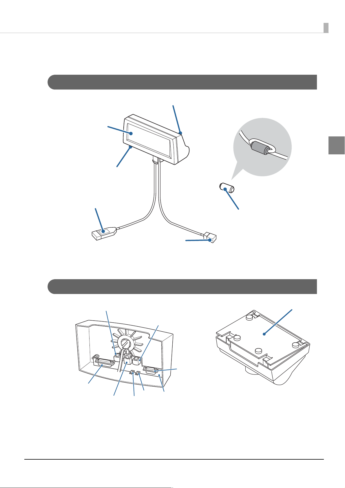
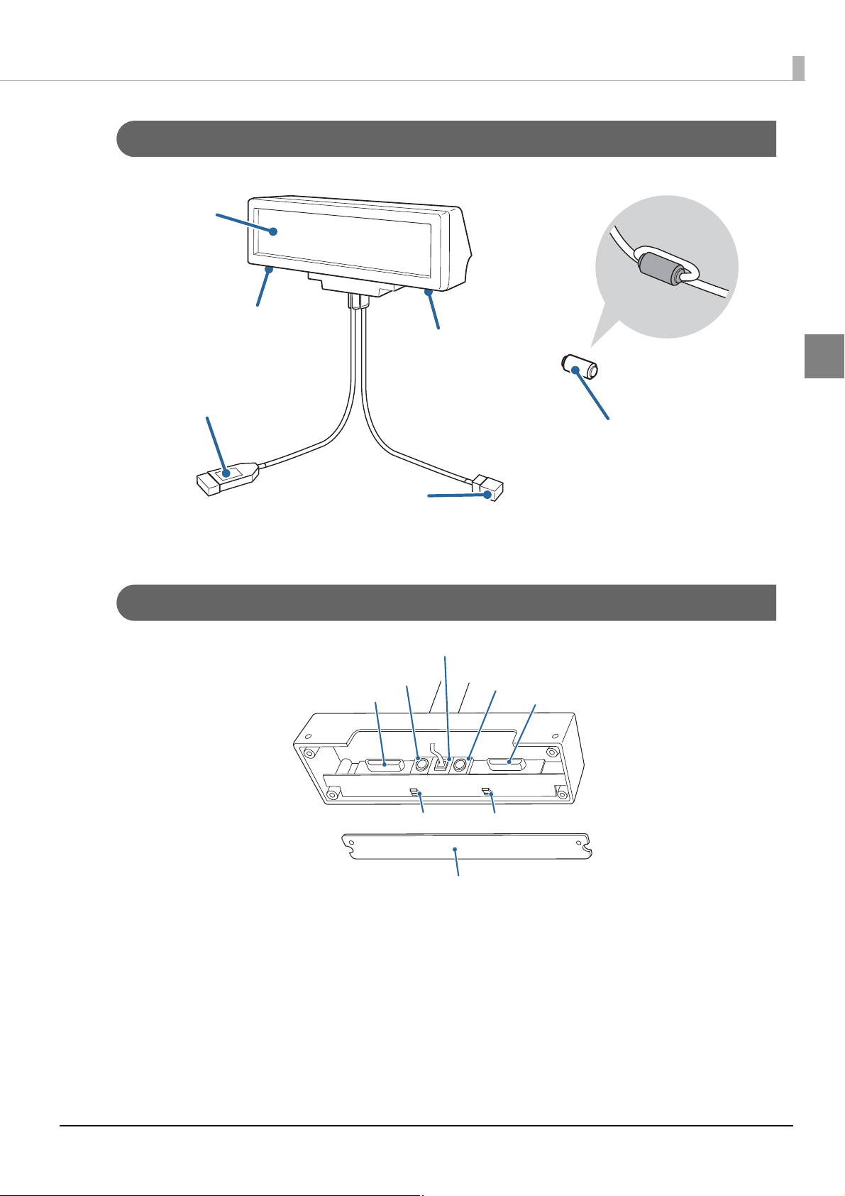
Part Names
Dip switch (rear side)
Power Switch
*1
(bottom side of the display)
Screen
Ferrite core
*1 *2
USB cable
*2
(with a cap *1)
RS-232 cable
*1
(with a cap *2)
Plate
JP1
JP2
Printer interface
connector
Extension power cable connector
Power supply connector
DM-D connector
Computer interface
connector
Interface board
(Not attached to DP-110 without Interface Board.)
DM-D110
Chapter 1 Product Overview
1
∗1 For the USB model, the power switch, ferrite core, USB cable cap and RS-232 cable are not included.
∗2 For the RS-232 model, the USB cable, RS-232 cable cap and ferrite core are not included.
DP-110
12
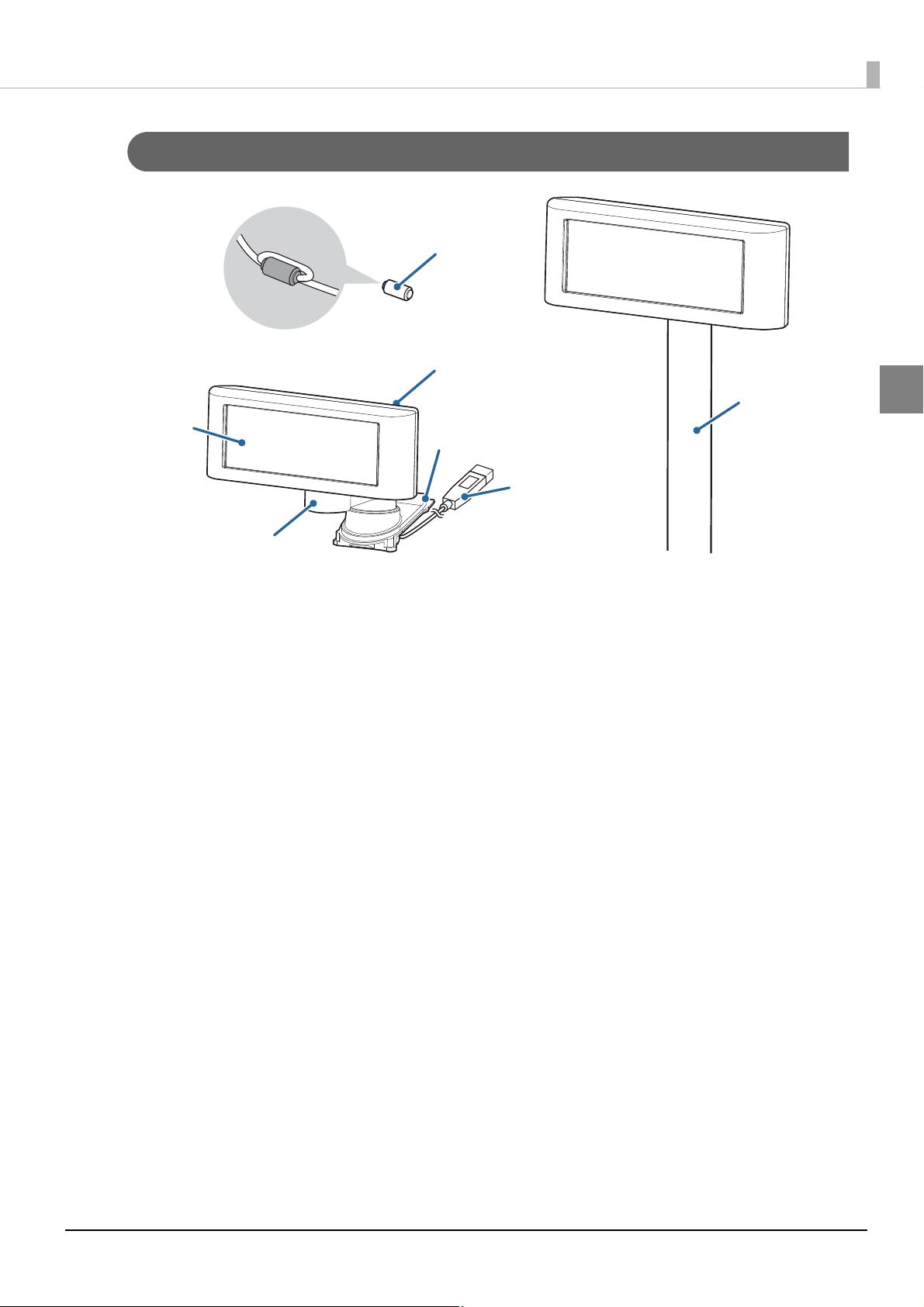
DM-D110 for TM-T88V-DT/TM-T88VI-DT2
Dip switch (rear side)
Base
Screen
L-shaped pole
USB cable
(with a cap
*
)
Straight pole
Ferrite core
*
Chapter 1 Product Overview
1
∗ They may not be supplied for DM-D110 for TM-T88V-DT/TM-T88VI-DT2 depending on when the product is shipped.
13
DM-D210
Dip switch
(bottom side of the display)
Screen
Power Switch
(bottom side of the display)
Ferrite core
*
USB cable
*
(with a cap)
RS-232 cable
(with a cap
*
)
DM-D connector
Plate
JP2
Printer interface connector
Extension power cable connector
Power supply connector
Computer interface connector
JP1
Chapter 1 Product Overview
1
∗ For the RS-232 model, the USB cable, RS-232 cable cap and ferrite core are not included.
DP-210
14
Chapter 1 Product Overview
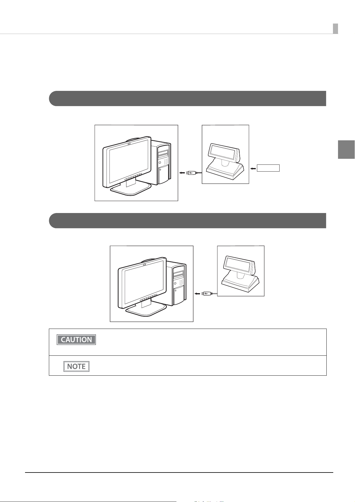
Computer DM-D110
USB
System Outline
This section explains the system connection pattern using this product.
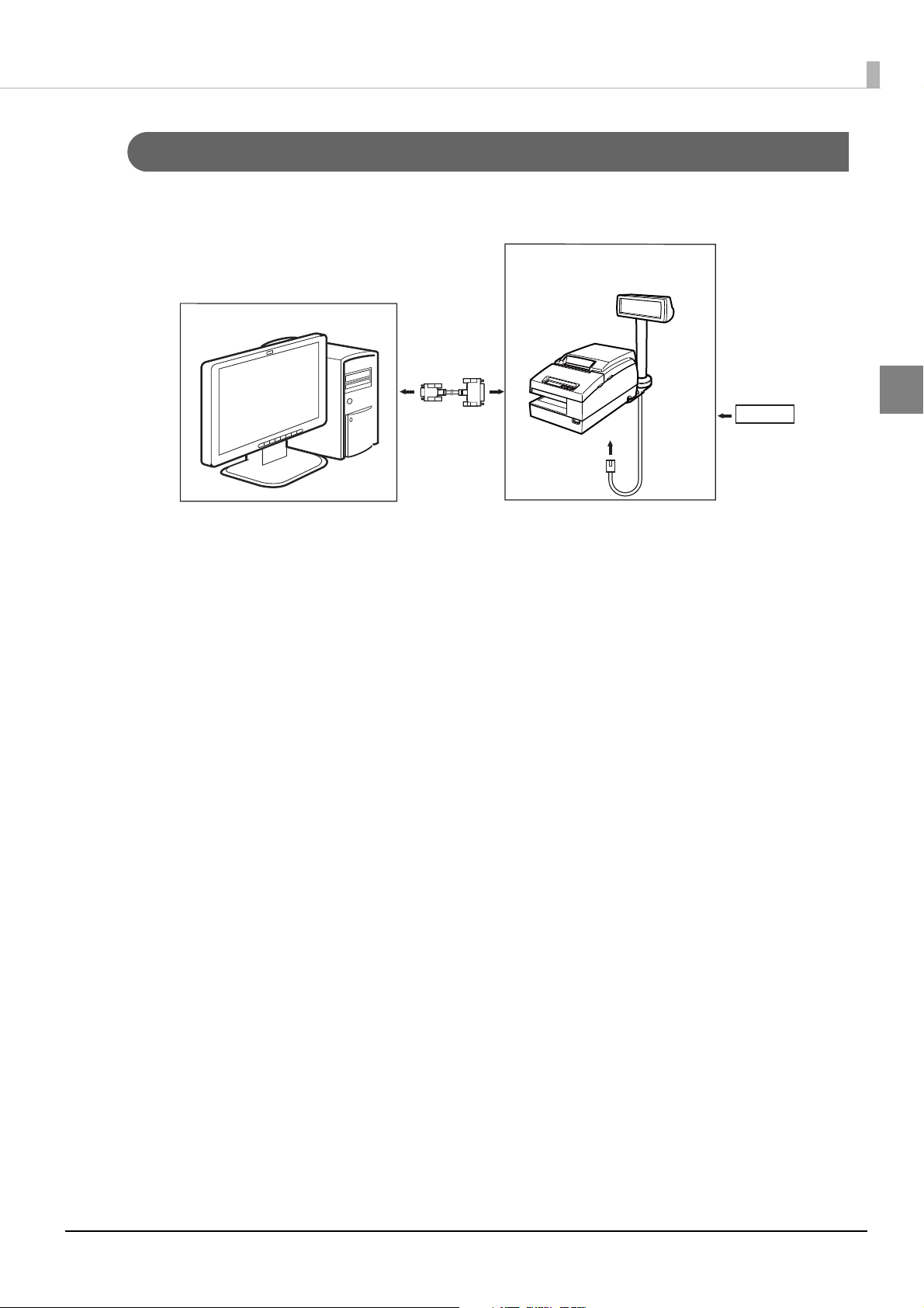
USB (Self Powered)
Connect this product’s USB cable to the computer, and then connect the RS-232 cable to DP-110/DP-210.
Computer
USB
DM-D110/DM-D210
PS-180
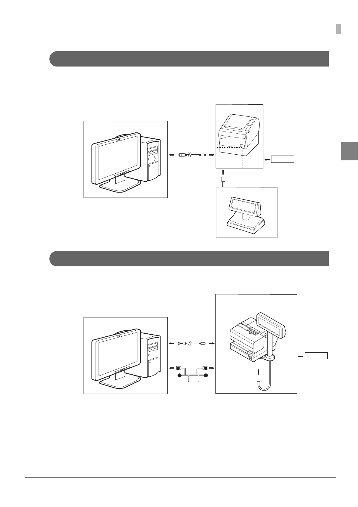
USB (Bus Powered): Computer
Connect this product’s USB cable to the computer. Power is supplied from the computer.
1
This product consumes the bus power that is close to the upper limit of the USB (USB2.0)
standards. Connect to a USB bus that has sufficient power supply capability. Otherwise
brightness may decline. Be careful when connecting to a laptop computer or a USB hub.
DM-D110: You can use the RS-232/USB and USB models.
DM-D210: You cannot use it.
15
Chapter 1 Product Overview
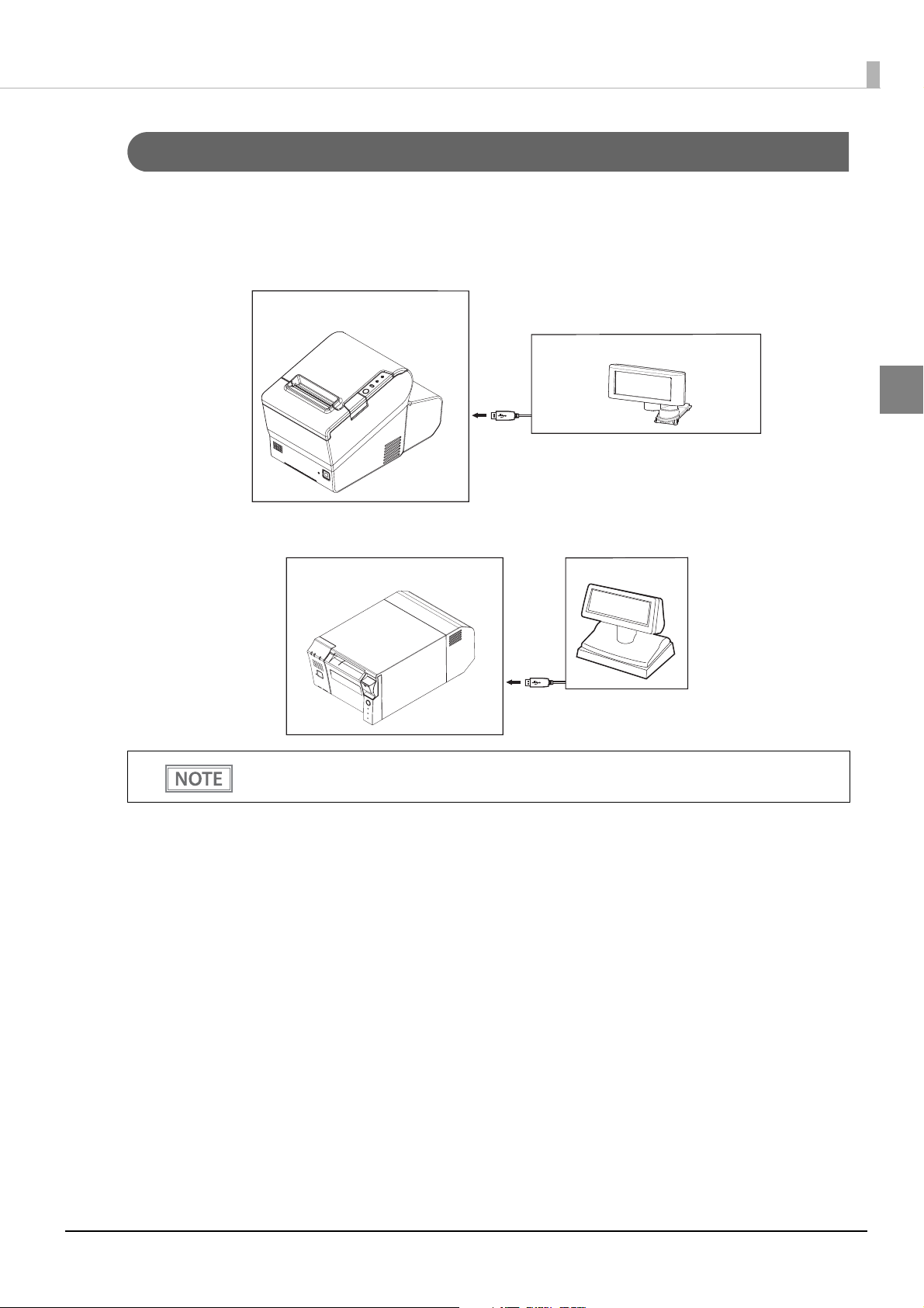
DM-D110 for TM-T88V-DT/TM-T88VI-DT2
TM-T88V-DT/TM-T88VI-DT2
USB
TM Intelligent Printer
DM-D110
USB
USB (Bus Powered): TM Intelligent Printer
Connect this product’s USB cable to the TM intelligent printer. Power is supplied from the TM intelligent
printer.
TM-T88V-DT/TM-T88VI-DT2 (Attach DM-D110 for TM-T88V-DT/TM-T88VI-DT2)
1
TM-DT series/TM-i series
DM-D110: You can use the RS-232/USB and USB models.
DM-D210: You cannot use it.
16
Chapter 1 Product Overview
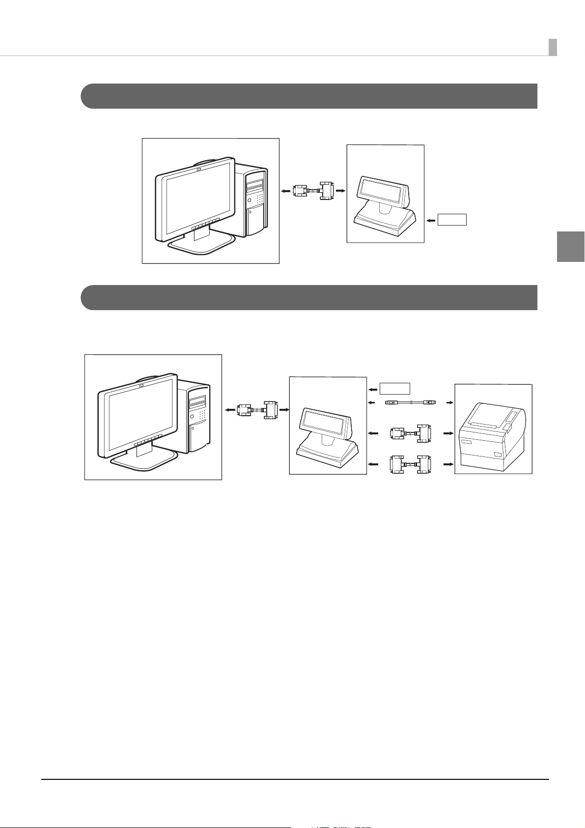
DM-D110/DM-D210
PS-180
Computer
Serial
TM Printer
Power extension cable
Computer
DM-D110/DM-D210
PS-180
Serial
Serial(DP-110)
Serial(DP-210)
Serial (Stand-Alone)
Connect DP-110/DP-210 to the computer using a serial cable.
Serial (Pass-through)
Connect the serial interface TM printer to the DP-110/DP210 connected to the computer using a serial connection. The power to the TM printer is supplied from DP-110/DP-210 via a power extension cable.
1
17
Chapter 1 Product Overview
TM Printer
DM-D110/DM-D210
PS-180
Serial
RS-232
Computer
Serial (Y-type)
Connect this product’s RS-232 cable to the TM printer DM-D connector, and then connect the TM printer and
the computer using a serial cable. Power is supplied from the TM printer.
1
18
Chapter 1 Product Overview
TM Printer
DM-D110/DM-D210
RS-232
USB
Ethernet
Computer
PS-180
Serial (USB controlled)
Connect this product's RS-232 cable to the DM-D connector on the UB-U01III or UB-U02III of the TM
printer, and then connect the TM printer and the computer using the USB cable.
Power is supplied from the TM printer.
TM Printer
Computer
USB
UB-U02III
RS-232
DM-D110/DM-D210
PS-180
UB-U01III/
Serial (USB/Ethernet controlled)
Connect this product's RS-232 cable to the DM-D connector of the TM printer, and then connect the TM
printer and computer by using a USB cable or via the network. Power is supplied from the TM printer.
1
19
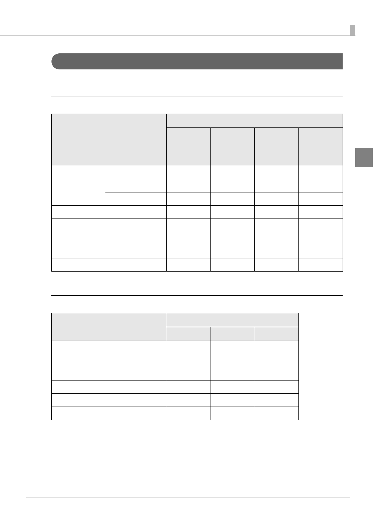
Connection patterns by options
The following table shows the connection pattern you can use for each option.
DM-D110 (except DM-D110 for TM-T88V-DT/TM-T88VI-DT2)
Option
Chapter 1 Product Overview
Connection Pattern
DP-110
USB (Self Powered) ✔ ---
USB (Bus Powered) Computer ✔✔ --
TM Intelligent Printer - ✔✔
Serial (Stand-Alone) ✔ ---
Serial (Pass-through) ✔ ---
Serial (Y-type) ✔✔✔✔
Serial (USB controlled) ✔✔✔✔
Serial (USB/Ethernet controlled) - - ✔ -
∗ Attached to TM-H6000IV-DT
DP-110
without
Interface
Board
DP-502 DP-503
*
-
DM-D210
1
Option
Connection Pattern
DP-210 DP-502 DP-503
USB (Self Powered) ✔ --
Serial (Stand-Alone) ✔ --
Serial (Pass-through) ✔ --
Serial (Y-type) ✔✔✔
Serial (USB controlled) ✔✔✔
Serial (USB/Ethernet controlled) - ✔ -
20
Setup
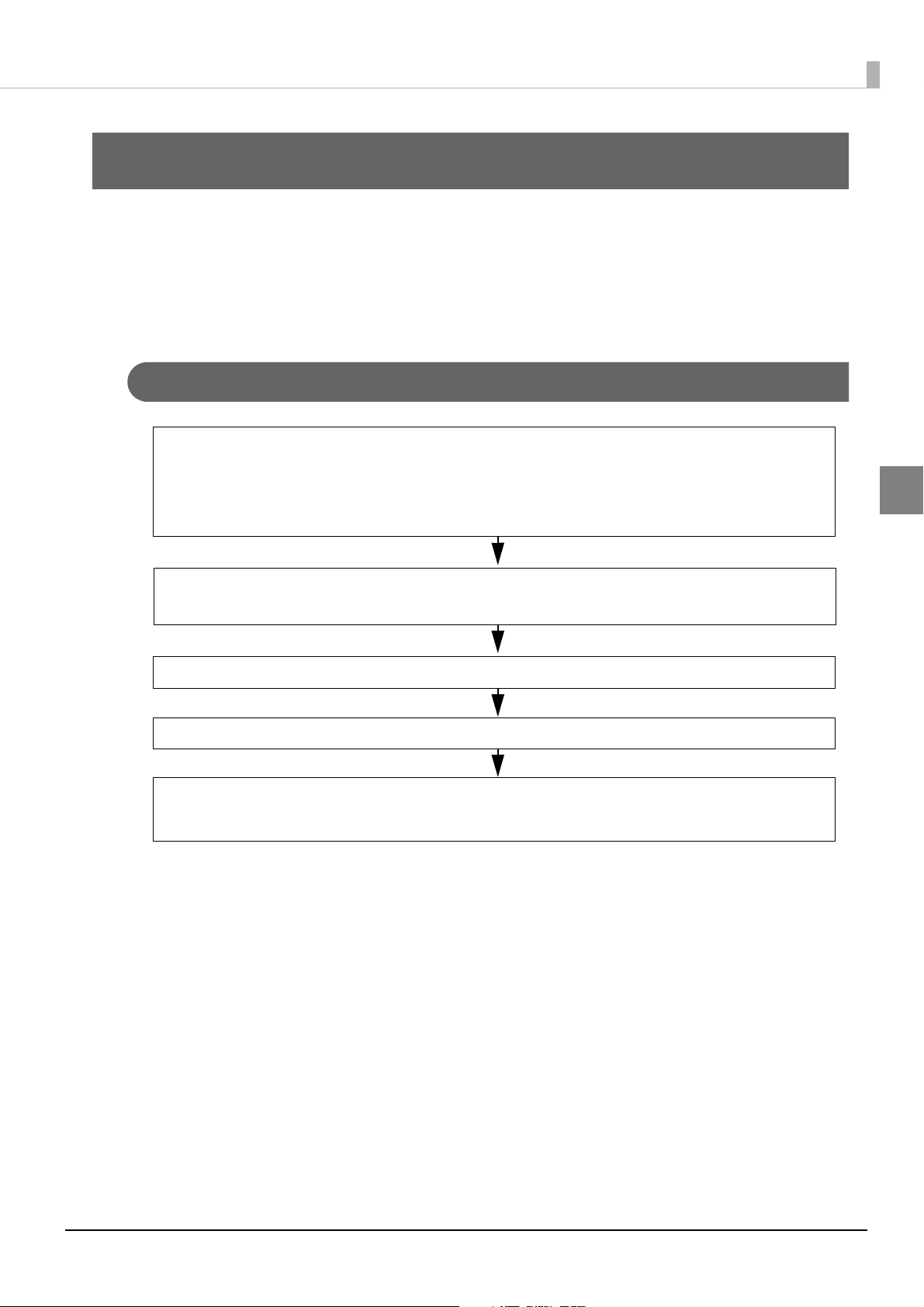
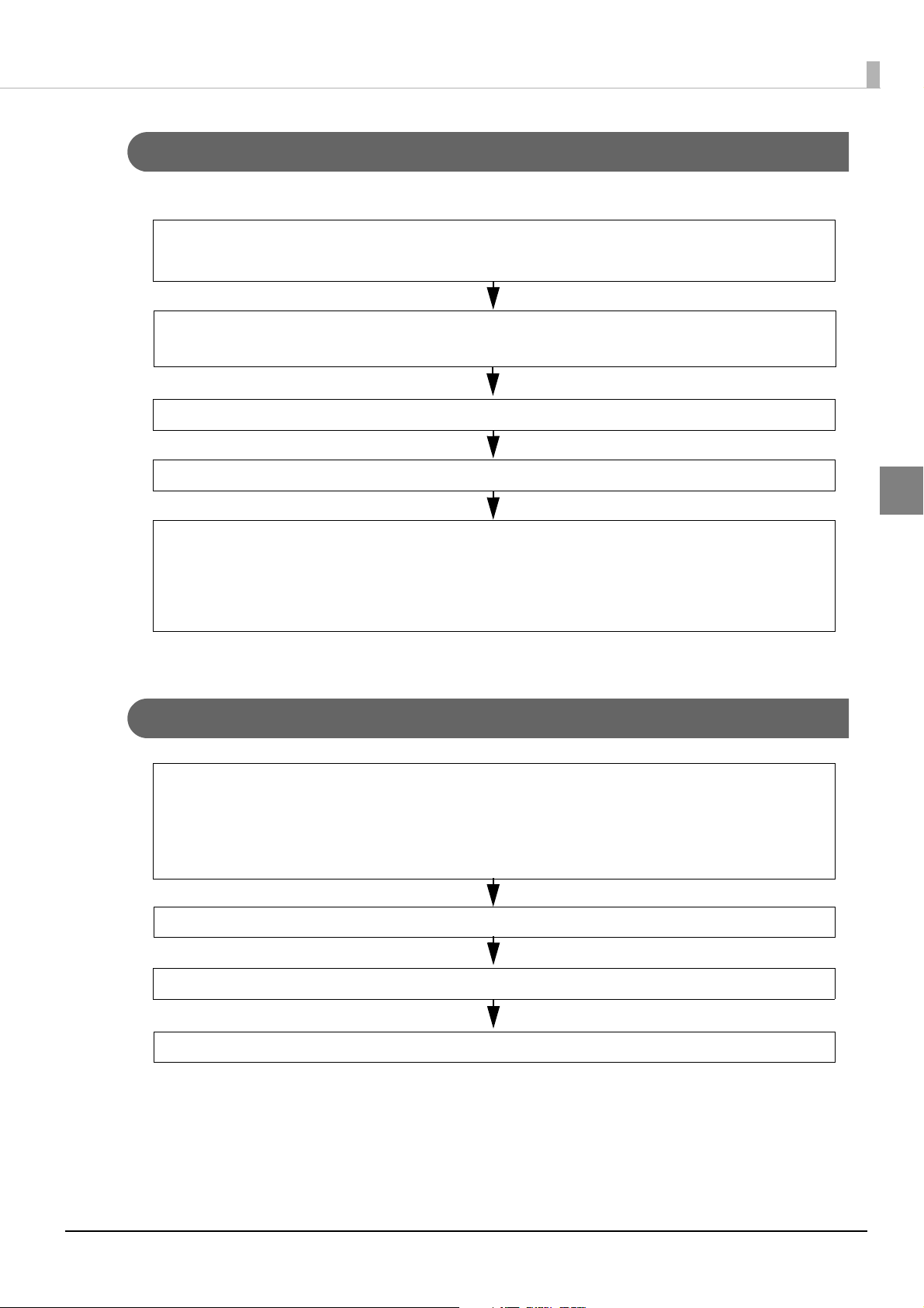
Connecting Cables (page 74)
Preparation
• Option (DP-110 */DP-210)
• AC adapter
• Power cord
Attaching the Product (page 30)
Installing the DM-D110 Virtual COM Port Driver to the Computer
For details, see the manual supplied with the DM-D110 Virtual COM Port Driver.
Dip Switch Settings (page 27)
Set the communication speed to 115200 bps.
This chapter explains the installation and setting operations necessary to use this product.
Setup Flow
This section explains the setup flow by connection patterns.
USB (Self Powered)
Chapter 2 Setup
2
∗ When extending the length of the support, prepare the option of DP-105.
21
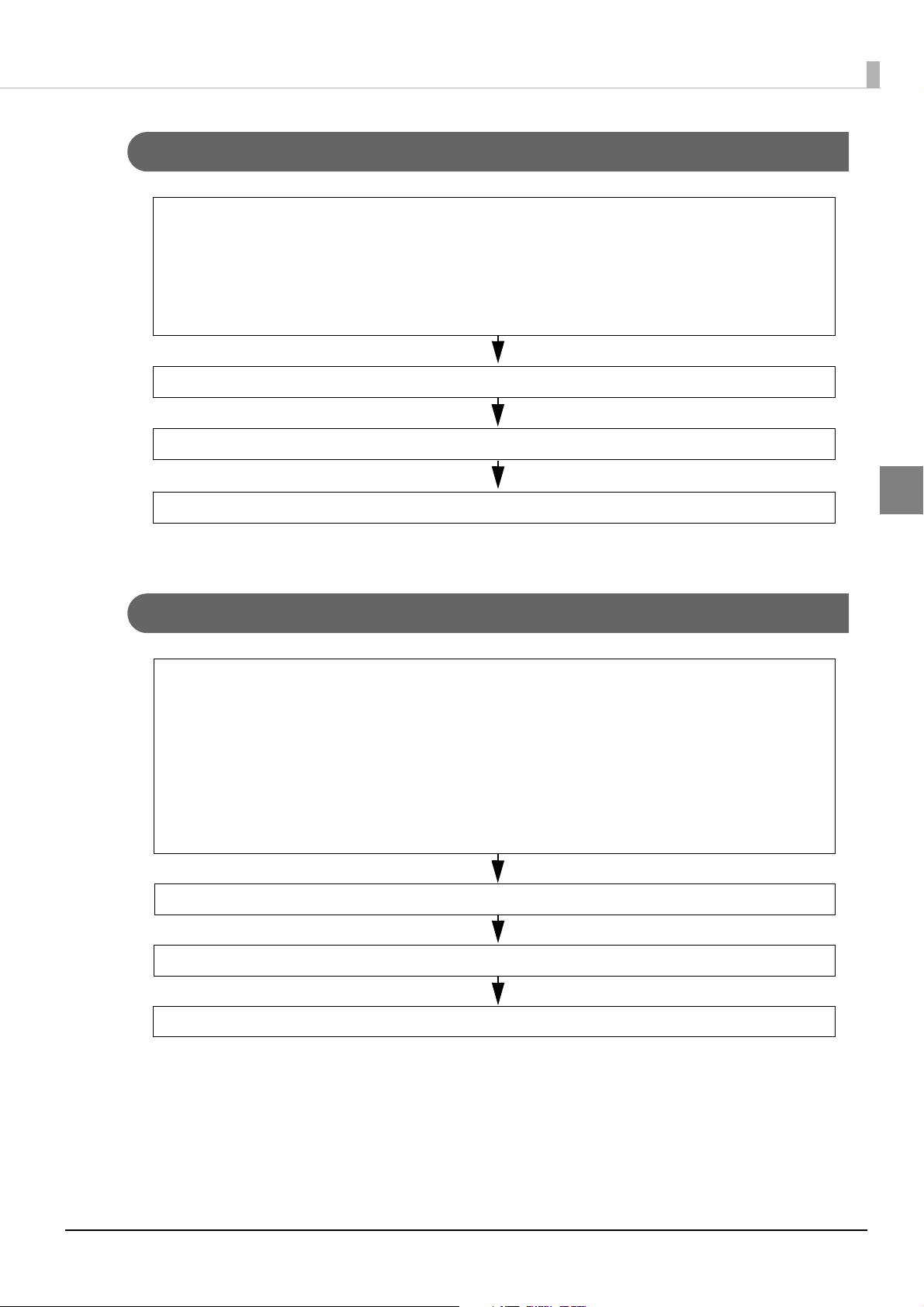
USB (Bus Powered): Computer
Preparation
• Option (DP-110 *)
Attaching the Product (page 30)
Connecting Cables (page 75)
Installing the DM-D110 Virtual COM Port Driver to the Computer
For details, see the manual supplied with the DM-D110 Virtual COM Port Driver.
For the TM-i series host, you do not need the DM-D110 Virtual COM Port Driver.
For the TM-DT series host, the DM-D110 Virtual COM Port Driver is already installed.
Dip Switch Settings (page 27)
Set the communication speed to 115200 bps.
Preparation
• DM-D110 for TM-T88V-DT/TM-T88VI-DT2: Options is Unnecessary
• DM-D110: DP-110
*
• TM Intelligent Printer
Attaching the Product (page 30)
Dip Switch Settings (page 27)
Connecting Cables to TM intelligent printer (page 75)
Power is supplied from the computer USB port.
Chapter 2 Setup
2
∗ When extending the length of the support, prepare the option of DP-105.
USB (Bus Powered): TM Intelligent Printer
∗ When extending the length of the support, prepare the option of DP-105.
22
Serial (Stand-Alone)
Preparation
• Option (DP-110 */DP-210)
• AC adapter
• Power cord
• Serial cable (page 106)
Attaching the Product (page 30)
Dip Switch Settings (page 27)
Connecting Cables (page 76)
Preparation
• Option (DP-110 */DP-210)
• AC adapter
• Power cord
• TM Printer (Serial interface)
• Serial cable for computer connection (page 106)
• S
erial cable for TM printer connection (page 106)
Attaching the Product (page 30)
Dip Switch Settings (page 27)
Connecting Cables (page 77)
Chapter 2 Setup
2
∗ When extending the length of the support, prepare the option of DP-105.
Serial (Pass-through)
∗ When extending the length of the support, prepare the option of DP-105.
23
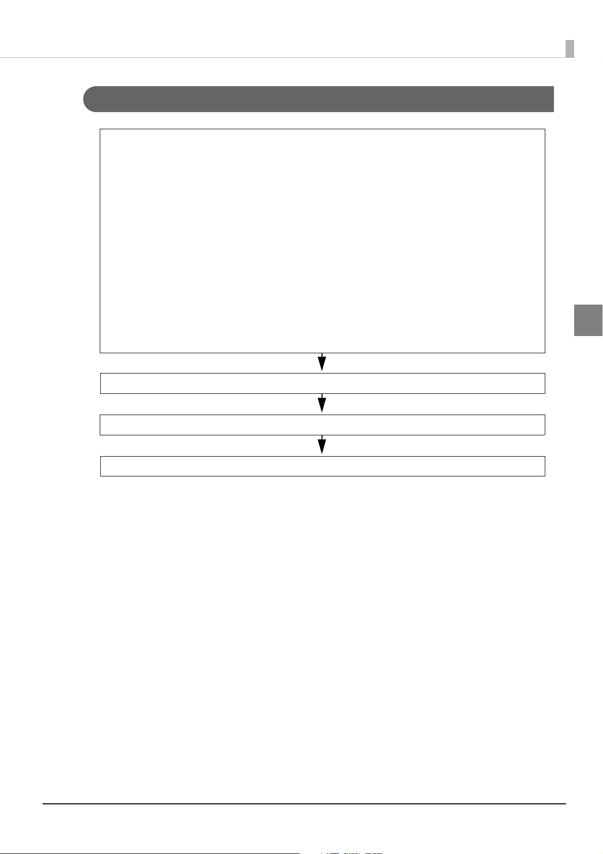
Serial (Y-type)
Preparation
• DM-D110: Select from the following options
• DP-110
*
• DP-502
• DP-503
• DM-D210: Select from the following options
• DP-210
• DP-502
• DP-503
• TM Printer (with DM-D connector, Serial interface)
• AC adapter
• Power cord
Attaching the Product (page 30)
Dip Switch Settings (page 27)
Connecting Cables (page 78)
Chapter 2 Setup
2
∗ When extending the length of the support, prepare the option of DP-105.
24

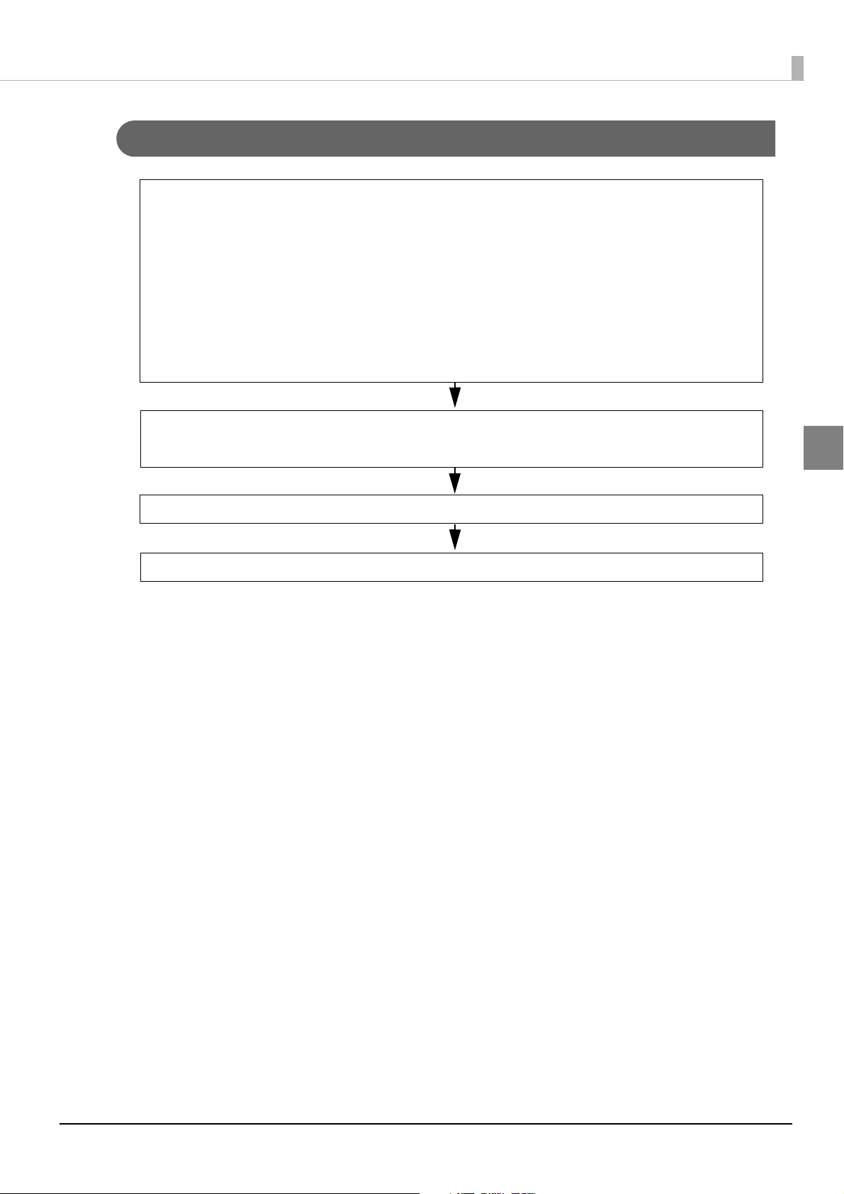
Serial (USB controlled)
Preparation
• DM-D110: Select from the following options
• DP-110
*
• DP-502
• DP-503
• DM-D210: Select from the following options
• DP-210
• DP-502
• DP-503
• TM Printer (with UB-U01III or UB-U02III)
• AC adapter
• Power cord
Attaching the Product (page 30)
Dip Switch Settings (page 27)
Set the communication speed to 19200 bps.
Connecting Cables (page 79)
Chapter 2 Setup
2
∗ When extending the length of the support, prepare the option of DP-105.
25
Serial (USB/Ethernet controlled)
Preparation
• DM-D110
• DP-502
• DM-D210
• DP-502
• TM Printer
• AC adapter
• Power cord
Attaching the Product (page 30)
Dip Switch Settings (page 27)
Set the communication speed to 19200 bps.
Connecting Cables (page 80)
Chapter 2 Setup
2
26

Chapter 2 Setup
Dip Switch Settings
Use the dip switch to set the communication conditions and whether or not to perform self test when the power
is turned on.
Settings by connection patterns
Set the dip switch for each connection pattern.
Connection Pattern Settings
USB (Self Powered/Bus Powered) When using the followings, set the communication speed to 115200 bps.
• EPSON OPOS ADK
• EPSON OPOS ADK for .NET
• EPSON JavaPOS ADK
Serial (Stand-Alone) Match the serial communication settings for the computer and this product.
Serial (Pass-through) Match the serial communication settings for the computer, printer and this prod-
uct.
Serial (Y-type) Match the serial communication settings for the computer, printer and this prod-
uct.
Serial (USB controlled) Set the communication speed to 19200 bps.
Serial (USB/Ethernet controlled) Set the communication speed to 19200 bps.
TM Intelligent Printer (ePOS-Device) Match the serial communication settings for the TM intelligent printer’s EPSON
TMNet WebConfig and this product.
TM-DT Series (Windows) Match the serial communication settings for the TM-DT Series and this product.
2
27
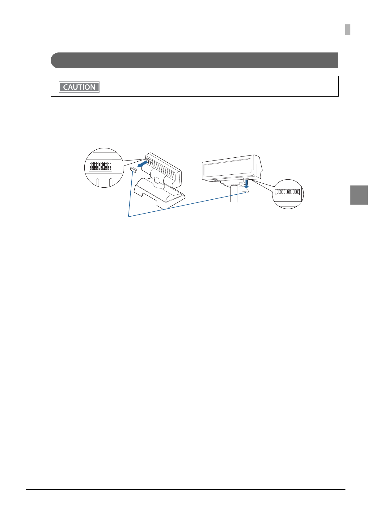
Setting method
ON
1234
5
67
8
910
1234
5
67
8910
DM-D110 DM-D210
DIP Switch Cover
Do not remove the DIP switch cover until after turning the power off. Removing the cover while
the power is turned on may damage the device.
Turn off the power of the this product and system, and remove cable.
1
Remove the DIP switch cover.
2
Chapter 2 Setup
2
Change each setting of the switches
3
Refer to "DIP Switch 1 Functions" on page 29 for the function of DIP switch.
Attach the DIP switch cover, and turn on the power of this product and the system.
4
28
Chapter 2 Setup
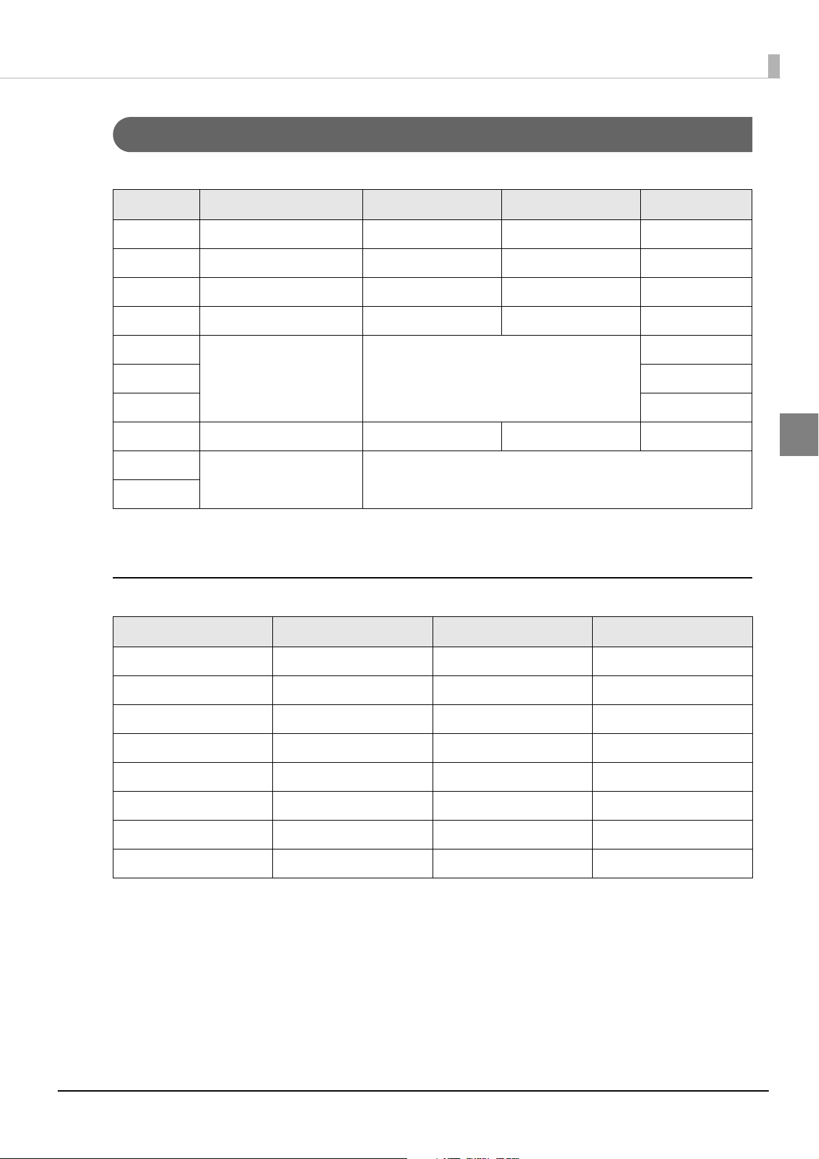
DIP Switch 1 Functions
The following explains the DIP switch functions.
DSW1 No. Function ON OFF Default Setting
1-1 Received Error Data Ignore Ignore "?" Display OFF
1-2 Receive Data Length 7 bit 8 bit OFF
1-3 Parity With Parity No Parity OFF
1-4 Parity Selection Even Odd OFF
1-5
1-6 OFF
1-7 ON
1-8
*2
1-9
*2
1-10
Communication Speed
Switching
Execute Self-Test
Not used Fixed to OFF
*1
Refer to " Transfer Speed Switching"
Yes No O FF
∗1 Executes the self-test once only when the power is turned on.
∗2 This is not available for the specifications model that has the dip switch with 8 poles.
Transfer Speed Switching
SW1-5 SW1-6 SW1-7 Transfer Speed (bps)
ON ON ON 2400
OFF ON ON 4800
ON OFF ON 9600
OFF OFF ON 19200
ON
2
*1
*2
ON ON OFF 38400
OFF ON OFF 57600
ON OFF OFF 115200
OFF OFF OFF (Reserved)
∗1 Default Setting
∗2 Settings when connecting using a serial (USB controlled)
29

Attaching the Product
This section explains how to attaching this product and the options.
Model Attaching Methods Page
DP-110 Attach DM-D110 to the optional DP-110. page 31
DP-210 Attach DM-D210 to the optional DP-210. page 35
DP-502 Use the optional DP-502 to attach DM-D110/DM-D210 to TM-H6000V. page 38
Chapter 2 Setup
Use the optional DP-502 to attach DM-D110/DM-D21
Use the optional DP-502 to attach DM-D110 to TM-H6000IV-DT. page 50
Use the optional DP-502 to attach DM-D110/DM-D210 to TM-U950. page 56
Use the optional DP-502 to attach DM-D110/DM-D210 to TM-J7200/ TM-J7700. page 59
Use the optional DP-502 to attach DM-D110/DM-D210 to the counter. page 63
DP-503 Use the optional DP-503 to attach DM-D110/DM-D210 to TM-H5000II. page 66
DM-D110 for
TM
-T88V-DT/
TM-T88VI-DT2
Attach DM-D110 for TM-T88V-DT/TM-T88VI-DT2 to TM-T88V-DT/TM-T88VI-DT2. page 68
0 to TM-H6000IV/TM-U675. page 44
2
30
 Loading...