

Page 1

SERVICE MANUAL
Color Inkjet Printer
EPSON Stylus C87/C88/D88
SEIJ05-002
Page 2

Notice:
All rights reserved. No part of this manual may be reproduced, stored in a retrieval system, or transmitted in any form or by any means, electronic, mechanical,
photocopying, recording, or otherwise, without the prior written permission of SEIKO EPSON CORPORATION.
The contents of this manual are subject to change without notice.
All effort have been made to ensure the accuracy of the contents of this manual. However, should any errors be detected, SEIKO EPSON would greatly appreciate being
informed of them.
The above not withstanding SEIKO EPSON CORPORATION can assume no responsibility for any errors in this manual or the consequences thereof.
EPSON is a registered trademark of SEIKO EPSON CORPORATION.
General Notice: Other product names used herein are for identification purpose only and may be trademarks or registered trademarks of their
respective owners. EPSON disclaims any and all rights in those marks.
Copyright © 2005 SEIKO EPSON CORPORATION.
I&I CS/Quality Management & PL Department
Page 3

PRECAUTIONS
Precautionary notations throughout the text are categorized relative to 1)Personal injury and 2) damage to equipment.
DANGER Signals a precaution which, if ignored, could result in serious or fatal personal injury. Great caution should be exercised in performing procedures preceded by
DANGER Headings.
WARNING Signals a precaution which, if ignored, could result in damage to equipment.
The precautionary measures itemized below should always be observed when performing repair/maintenance procedures.
DANGER
1. ALWAYS DISCONNECT THE PRODUCT FROM THE POWER SOURCE AND PERIPHERAL DEVICES PERFORMING ANY MAINTENANCE OR REPAIR
PROCEDURES.
2. NO WORK SHOULD BE PERFORMED ON THE UNIT BY PERSONS UNFAMILIAR WITH BASIC SAFETY MEASURES AS DICTATED FOR ALL ELECTRONICS
TECHNICIANS IN THEIR LINE OF WORK.
3. WHEN PERFORMING TESTING AS DICTATED WITHIN THIS MANUAL, DO NOT CONNECT THE UNIT TO A POWER SOURCE UNTIL INSTRUCTED TO DO
SO. WHEN THE POWER SUPPLY CABLE MUST BE CONNECTED, USE EXTREME CAUTION IN WORKING ON POWER SUPPLY AND OTHER ELECTRONIC
COMPONENTS.
4. WHEN DISASSEMBLING OR ASSEMBLING A PRODUCT, MAKE SURE TO WEAR GLOVES TO AVOID INJURIER FROM METAL PARTS WITH SHARP EDGES.
WARNING
1. REPAIRS ON EPSON PRODUCT SHOULD BE PERFORMED ONLY BY AN EPSON CERTIFIED REPAIR TECHNICIAN.
2. MAKE CERTAIN THAT THE SOURCE VOLTAGES IS THE SAME AS THE RATED VOLTAGE, LISTED ON THE SERIAL NUMBER/RATING PLATE. IF THE
EPSON PRODUCT HAS A PRIMARY AC RATING DIFFERENT FROM AVAILABLE POWER SOURCE, DO NOT CONNECT IT TO THE POWER SOURCE.
3. ALWAYS VERIFY THAT THE EPSON PRODUCT HAS BEEN DISCONNECTED FROM THE POWER SOURCE BEFORE REMOVING OR REPLACING PRINTED
CIRCUIT BOARDS AND/OR INDIVIDUAL CHIPS.
4. IN ORDER TO PROTECT SENSITIVE MICROPROCESSORS AND CIRCUITRY, USE STATIC DISCHARGE EQUIPMENT, SUCH AS ANTI-STATIC WRIST
STRAPS, WHEN ACCESSING INTERNAL COMPONENTS.
5. REPLACE MALFUNCTIONING COMPONENTS ONLY WITH THOSE COMPONENTS BY THE MANUFACTURE; INTRODUCTION OF SECOND-SOURCE ICs OR
OTHER NON-APPROVED COMPONENTS MAY DAMAGE THE PRODUCT AND VOID ANY APPLICABLE EPSON WARRANTY.
6. WHEN USING COMPRESSED AIR PRODUCTS; SUCH AS AIR DUSTER, FOR CLEANING DURING REPAIR AND MAINTENANCE, THE USE OF SUCH
PRODUCTS CONTAINING FLAMMABLE GAS IS PROHIBITED.
Page 4

About This Manual
This manual describes basic functions, theory of electrical and mechanical operations, maintenance and repair procedures of the printer. The instructions and procedures included
herein are intended for the experienced repair technicians, and attention should be given to the precautions on the preceding page.
Manual Configuration
This manual consists of six chapters and Appendix.
CHAPTER 1.PRODUCT DESCRIPTIONS
Provides a general overview and specifications of the product.
CHAPTER 2.OPERATING PRINCIPLES
Describes the theory of electrical and mechanical operations of the
product.
CHAPTER 3.TROUBLESHOOTING
Describes the step-by-step procedures for the troubleshooting.
CHAPTER 4.DISASSEMBLY / ASSEMBLY
Describes the step-by-step procedures for disassembling and assembling
the product.
CHAPTER 5.ADJUSTMENT
Provides Epson-approved methods for adjustment.
CHAPTER 6.MAINTENANCE
Provides preventive maintenance procedures and the lists of Epsonapproved lubricants and adhesives required for servicing the product.
APPENDIX Provides the following additional information for reference:
• Exploded Diagram
• Parts List
• Circuit Diagrams
Symbols Used in this Manual
Various symbols are used throughout this manual either to provide additional
information on a specific topic or to warn of possible danger present during a
procedure or an action. Be aware of all symbols when they are used, and always read
NOTE, CAUTION, or WARNING messages.
A D J U S T M E N T
R E Q U I R E D
C A U T I O N
C H E C K
P O I N T
W A R N I N G
Indicates an operating or maintenance procedure, practice or condition
that is necessary to keep the product’s quality.
Indicates an operating or maintenance procedure, practice, or condition
that, if not strictly observed, could result in damage to, or destruction of,
equipment.
May indicate an operating or maintenance procedure, practice or
condition that is necessary to accomplish a task efficiently. It may also
provide additional information that is related to a specific subject, or
comment on the results achieved through a previous action.
Indicates an operating or maintenance procedure, practice or condition
that, if not strictly observed, could result in injury or loss of life.
Indicates that a particular task must be carried out according to a certain
standard after disassembly and before re-assembly, otherwise the quality of the components in question may be adversely affected.
Page 5

Revision Status
Revision Date of Issue Description
A August 1 , 2005 First Release
Page 6

EPSON Stylus C87/C88/D88 Revision A
Contents
Chapter 1 PRODUCT DESCRIPTION
1.1 Features.................................................................................................................. 9
1.2 Specifications ...................................................................................................... 10
1.2.1 Physical Specification................................................................................. 10
1.2.2 Printing Specification ................................................................................. 10
1.2.3 Paper Feeding ............................................................................................. 11
1.2.4 Input Data Buffer........................................................................................ 11
1.2.5 Electric Specification.................................................................................. 11
1.2.6 Reliability ................................................................................................... 12
1.2.7 Acoustic Noise............................................................................................ 12
1.2.8 Black Ink Save Mode.................................................................................. 13
1.3 Operator Controls ................................................................................................ 14
1.3.1 Operation Switch ........................................................................................ 14
1.3.2 Panel Functions........................................................................................... 14
1.3.3 Printer Condition and LED Status .............................................................. 15
1.3.4 Duplex Printing........................................................................................... 15
1.3.5 Errors .......................................................................................................... 15
1.4 Paper .................................................................................................................... 16
1.4.1 Paper Support.............................................................................................. 16
1.5 Ink Cartridge........................................................................................................ 21
1.5.1 Ink Cartridge Specification......................................................................... 21
Chapter 2 OPERATING PRINCIPLES
Chapter 3 TROUBLESHOOTING
3.1 Overview ............................................................................................................. 30
3.1.1 Specified Tools ........................................................................................... 30
3.1.2 Preliminary Checks..................................................................................... 30
3.2 Troubleshooting With LED Error Indications.................................................... 31
3.2.1 Fatal Error................................................................................................... 33
3.3 Troubleshooting for Motors and Sensors ............................................................ 35
Chapter 4 DISASSEMBLY/ASSEMBLY
4.1 Overview ............................................................................................................. 37
4.1.1 Precautions.................................................................................................. 37
4.1.2 Tools ........................................................................................................... 37
4.1.3 Screws (T.B.D)........................................................................................... 38
4.1.4 Work Completion Check ............................................................................ 39
4.2 Caution regarding Assembling/Disassembling of the Printer Mechanism,
and How to Ensure of Quality on Re-assembled Product................................... 40
4.3 Dissasembly Procedures...................................................................................... 42
4.3.1 Removing Housings ................................................................................... 44
4.3.2 Removing Boards ....................................................................................... 57
4.3.3 Disassembling Printer Mechanism ............................................................. 62
Chapter 5 ADJUSTMENT
2.1 Overview ............................................................................................................. 24
2.2 Printer Mechanism............................................................................................... 24
2.2.1 Printhead Specifications ............................................................................. 25
2.2.2 Carriage Mechanism................................................................................... 25
2.2.3 Paper Loading/Feeding Mechanism ........................................................... 26
2.2.4 Ink System Mechanism............................................................................... 27
2.3 Electrical Circuit Operating Principles................................................................ 27
2.3.1 C528 PSH Board......................................................................................... 28
2.3.2 C528 Main Board ....................................................................................... 28
5.1 Adjustment Items and Overview......................................................................... 81
5.1.1 Servicing Adjustment Item List.................................................................. 81
5.1.2 Replacement Part-Based Adjustment Priorities ......................................... 84
5.2 Adjustment by Using Adjustment Program ........................................................ 85
5.2.1 Market ID Setting ....................................................................................... 85
5.2.2 USB ID Input.............................................................................................. 85
5.2.3 Head ID Input ............................................................................................. 85
5.2.4 Head Angular Adjustment.......................................................................... 86
5.2.5 Bi-D Adjustment......................................................................................... 86
6
Page 7

EPSON Stylus C87/C88/D88 Revision A
5.2.6 PF Adjustment ............................................................................................ 87
5.2.7 PW Sensor adjustment................................................................................ 87
5.2.8 First Dot Adjustment .................................................................................. 88
5.2.9 Top Margin Adjustment ............................................................................. 88
5.2.10 Offset input for CR Motor Calorific Limitation ....................................... 89
5.2.11 A4 Normal Paper print.............................................................................. 89
5.2.12 A4 Photo Quality Inkjet Paper Print........................................................ 90
5.3 Adjustment Except Adjustment Program ............................................................ 91
5.3.1 CR Timing Belt Tension adjustment .......................................................... 91
Chapter 6 MAINTENANCE
6.1 Overview ............................................................................................................. 93
6.1.1 Cleaning...................................................................................................... 93
6.1.2 Service Maintenance................................................................................... 93
6.1.3 Lubrication.................................................................................................. 95
Chapter 7 APPENDIX
7.1 Exploded Diagram............................................................................................... 99
7.2 Parts List............................................................................................................ 105
7.3 Circuit Diagram ................................................................................................. 106
7
Page 8

PRODUCT DESCRIPTION
CHAPTER
1
Page 9
EPSON Stylus C87/C88/D88 Revision A
1.1 Features
The major features of EPSON Stylus C87/C88/D88 are:
High color print quality
4-color pigment ink installed
High quality printing on plain papers
2880 (H) x 1440 (V) dpi printing (Max resolution)
Supports two types of I/F
Bidirectional parallel I/F
USB
Windows/Macintosh exclusive
Built-in auto sheet feeder (ASF)
Comes equipped with the ASF that supports from postcard-sized papers to
A4-sized papers
CSIC compatible fully independent ink cartridges
Borderfree printing for all sides
Prevents printing on platen with the optical sensor
Cancel print jobs function
Reduced noise during paper feeding
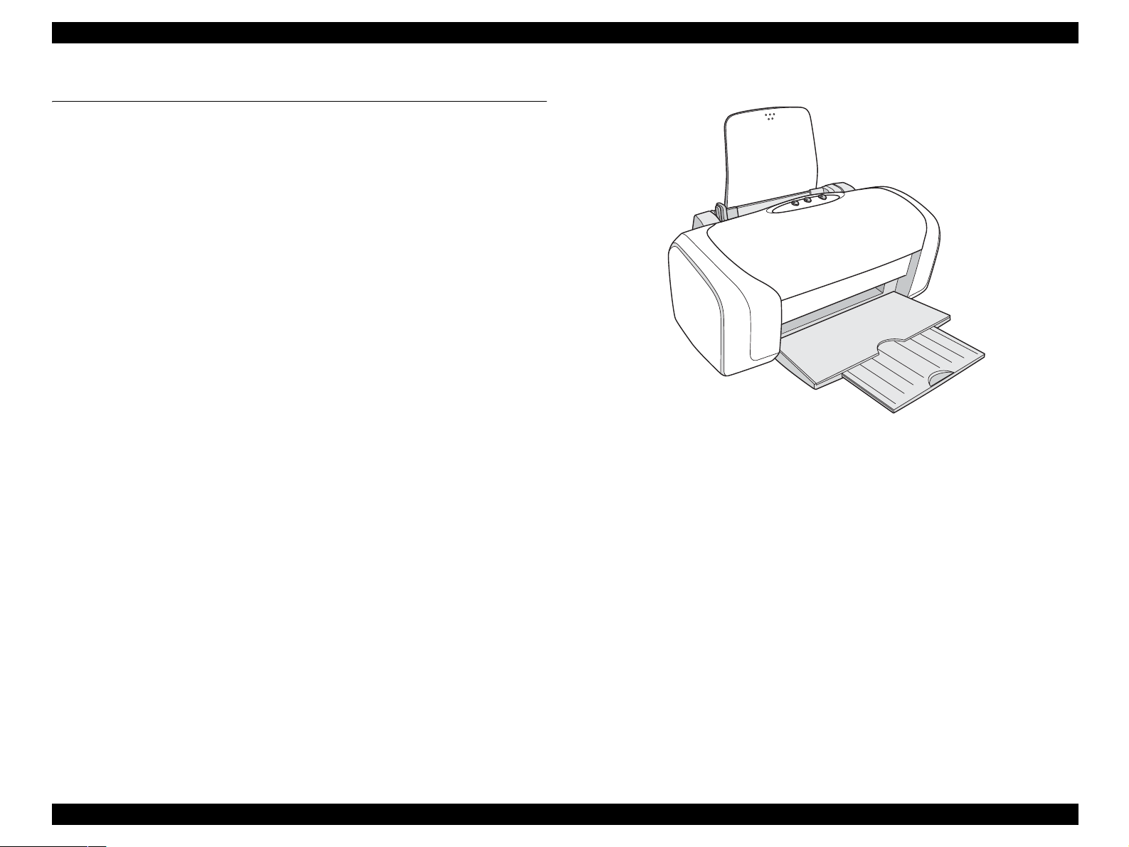
Figure 1-1. Product Appearance
PRODUCT DESCRIPTION Features 9
Page 10
EPSON Stylus C87/C88/D88 Revision A
1.2 Specifications
This section covers specifications of the printer.
1.2.1 Physical Specification
Weight: 4.2 kg (without the ink cartridges)
Dimension
Storage: 460 mm (W) x 242 mm (D) x 191.2 mm (H)
Printing: 460 mm (W) x 437 mm (D) x 309 mm (H)
1.2.2 Printing Specification
Print method
On demand ink jet
Nozzle configuration
monochrome: 180 nozzles
color: 59 nozzles x 3 (Cyan, Magenta, Yellow)
Print direction
Bi-direction with logic seeking
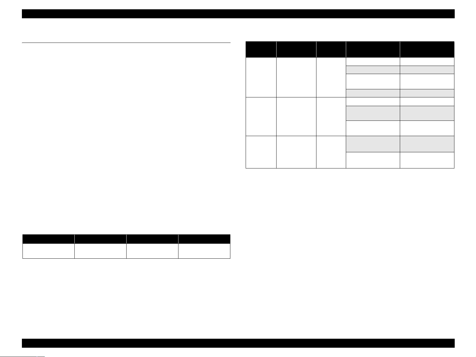
Print speed & Printable columns
Table 1-1. Character Mode
Character Quality Character Pitch Printable Columns CR Speed
High quality 10 CPI (Pitch) 80 digits
622.3 mm/s
(245 CPS)
Table 1-2. Raster Graphics Mode
Horizontal
resolution
360 dpi
720 dpi
1440 dpi
Printable area
209.8 mm
(8.26 inch)
209.8 mm
(8.26 inch)
209.8 mm
(8.26 inch)
Available
dot
2976
5952
11904
Control Code
ESC/P2 expanded raster graphics code
EPSON Remote command
Character tables
none (ASCII 20H to 7FH code support)
Internal fonts
Alphanumeric characters: Courier 10 CPI
Dot size CR speed
Eco 863.6 mm/s (340 CPS)
VSD1 622.3 mm/s (245 CPS)
VSD2
(Color)
VSD4 571.5 mm/s (225 CPS)
VSD2 622.3 mm/s (245 CPS)
VSD2'
(Black)
VSD3’
(Color)
VSD3
VSD3’
(Black)
622.3 mm/s (245 CPS)
622.3 mm/s (245 CPS)
736.6 mm/s (190 CPS)
736.6 mm/s (190 CPS)
736.6 mm/s (190 CPS)
PRODUCT DESCRIPTION Specifications 10
Page 11

EPSON Stylus C87/C88/D88 Revision A
1.2.3 Paper Feeding
Paper feeding method
Friction feed with ASF
PF interval
Programmable in 0.0175 mm (1/1440 inch)
Paper loading method
Friction feed
Feed speed
196.39 mm/sec (19.05 mm (0.75 inch) feed) (T.B.D)
352.8 mm/sec (High speed /Continuous feed) (T.B.D)
1.2.4 Input Data Buffer
Input buffer size: 128 KB
1.2.5 Electric Specification
Rated voltage: AC100 V - 240 V
Input voltage range: AC90 - 264 V
Safety approvals
UPS version:
Safety standards : UL1950
CSA C22.2 No.950
: EN 60950(VDE)
EMI : FCC part15 subpart B class B
CSA C108.8 class B
: EN 55022(CISPR Pub.22) class B
: AS/NZS 3548 class B
CE Marking
UPS version:
Low Voltage Directive 73/23/EEC : EN60950
EMC Directive 89/336/EEC : EN55022 Class B
EN61000-3-2
EN61000-3-3
EN55024
Rated frequency range: 50 - 60 Hz
Input frequency range: 49.5 - 60.5 Hz
Rated current: 0.4 A - 0.2 A
Power consumption: ISO10561 Letter Pattern: 19W
Sleep Mode: 4.5 W
Power Off Mode: 0.8 W
Dielectric resistance: 10 MΩ or more
(between AC line and chassis at DC 500 V)
Dielectric strength: AC 1500 V rms. 1 second
(between AC line and chassis)
PRODUCT DESCRIPTION Specifications 11
Page 12
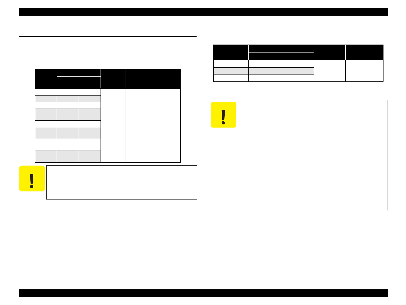
EPSON Stylus C87/C88/D88 Revision A
Environmental Condition
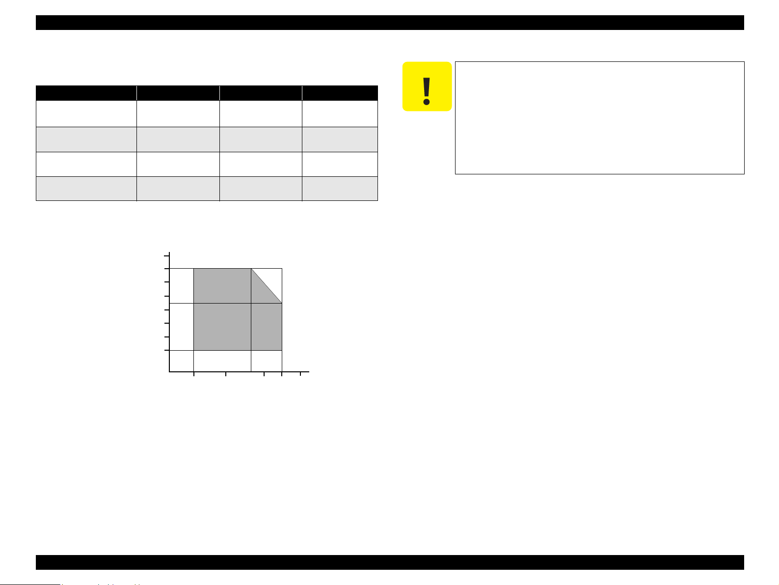
Table 1-3. Environmental Condition
Operating Non-operating
Temperature
Humidity (should be no
condensation)
Resistance to shock
(X, Y, and Z directions)
Resistance to vibration
(X, Y, and Z directions)
Note *1: One month at 40°C and 120 hours at 60°C
*2: Packed in the shipment container
*3: Under the following conditions
*1
Humidity(%)
10~35 °C
20~80 % RH 5~85 % RH ---
1 G, within 1 ms 2 G, within 2 ms ---
90
80
70
60
50
40
30
20
*3
0.15 G 0.50 G ---
-20~60 °C
*2
1 month at 40 °C
120 hours at 60 °C
C A U T I O N
Remarks
1.2.6 Reliability
Total print volume: 50,000 pages (A4, Letter) or five years,
Print Head Life: Three billion shots (per nozzle) or five years,
1.2.7 Acoustic Noise
Level: Approx. 42 db (A)
Printhead must be capped during storage.
When transporting the printer, make sure that the printhead is
capped and the ink cartridges are installed in the printer.
If the printhead is not capped when the printer is turned off,
turn the printer on with the ink cartridges installed, cap the
printhead, and turn the power off.
Ink inside the ink cartridges freezes if it is left to stand at
temperature of -4°C or less. If this is the case, allow the ink to
stand for about three hours at 25°C temperature.
whichever comes first.
whichever comes first.
27
10
20
35
30
40
Temperature (°C)
Figure 1-2. Temperature/Humidity Range
PRODUCT DESCRIPTION Specifications 12
Page 13
EPSON Stylus C87/C88/D88 Revision A
1.2.8 Black Ink Save Mode
“Black ink save mode” allows you to print images with color ink only when the
remaining amount of black ink is low. This mode can be selected when the remaining
amount of color ink is sufficient since black areas of the images are printed with a
mixture of other colors.
Supported OS: Windows NT4.0, 95, 98, ME, 2000, XP
Printing mode: Plain Paper & Text Mode (360 dpi)
Operating procedure
1. User carries out printing from an application.
2. The printer driver checks both the printing mode and the amount of remaining ink,
and displays the specific window if the conditions described below are all
satisfied.
Selected printing mode supports black ink save mode.
Remaining amount of black ink is less than 5 %, or the status of the black ink
is “ink low”.
Remaining amount of all the color ink is more than 10 %, or the status of all
the color ink is NOT “ink low”.
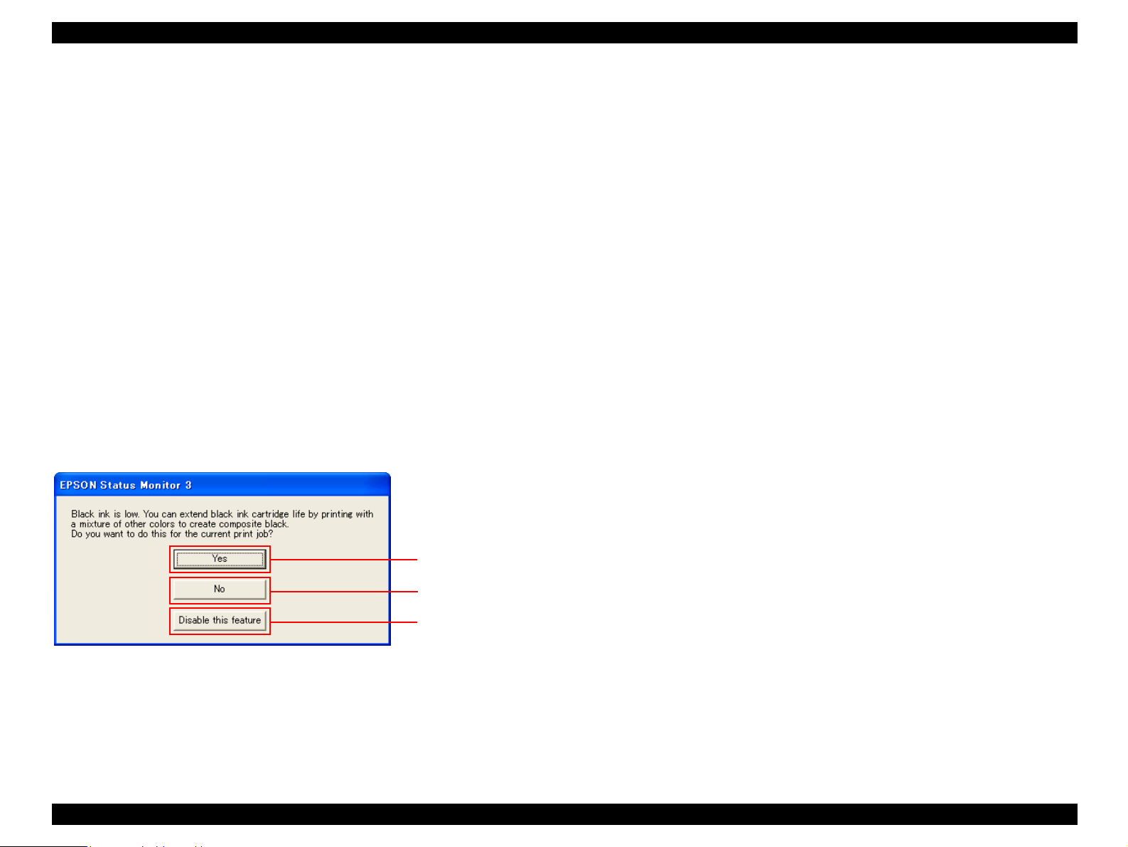
Starts printing in black ink save mode.
Starts printing in a
normal manner.
Starts printing in a
normal manner.
This window will not be
displayed until the black
ink cartridges is replaced.
Figure 1-3. Black Ink Save Mode Window
PRODUCT DESCRIPTION Specifications 13
Page 14

EPSON Stylus C87/C88/D88 Revision A
1.3 Operator Controls
1.3.1 Operation Switch
Operation switch is located on top center of the main unit.
1.3.1.1 Switches
There are three non-lock type push switches and three LEDs.
Ink switch
Ink LED
Paper switch
Paper LED
Power switch
Power LED
1.3.2 Panel Functions
Table 1-4. Panel Functions
Switch Function
Paper
Ink
Ink
(Holding down for three seconds)
Table 1-5. Panel functions with power on
Switch Pressing with Power On function
Paper + Power Starts status printings.
• Loads or ejects paper.
• Restarts when paper jam occurred.
• In the condition of printing, cancel the print job.
• Starts the ink cartridge change sequence. Moves the
carriage to cartridge change position.
• In the condition of ‘Ink Low’, ‘Ink Out’ or ‘No Ink
Cartridge’, moves the carriage to the ink check
position.
• When the carriage is on the ink check position, moves
carriage to next ink check position or cartridge change
position.
• When carriage is on the ink change position, returns
carriage from ink cartridge change position.
• Starts the cleaning of head.
• In the condition of 'Ink Low', 'Ink Out' or 'No Ink
Cartridge', starts the ink cartridge change sequence.
*
Figure 1-4. Control Panel
1.3.1.2 Indicators
Power LED [Green]
Lights when the power switch is “ON” and AC power is supplied.
Flashes when data is processed or ink system is operating.
Note *: Holding down the [Paper] switch, press [Power].
Table 1-6. Panel functions with power off
Switch Pressing with Power Off function
Ink + Power
Note *: Holding down the [Power] switch, press [Ink] for about seven seconds.
*
Compulsory power off.
*
Paper LED [Red]
Lights during the paper out/multi-feed condition, and flashes during the paper jam
condition.
Ink LED [Red]
Lights during no ink condition, and flashes during ink low condition.
PRODUCT DESCRIPTION Operator Controls 14
Page 15

EPSON Stylus C87/C88/D88 Revision A
1.3.3 Printer Condition and LED Status
Table 1-7. Printer Condition and LED Status
Printer status
Power on On -- -- 11
Ink level low -- -- Flashes 10
Data processing Flashes -- -- 9
No ink cartridge or ink end -- -- On 8
CSIC Error -- -- On 8
Ink sequence Flashes -- -- 7
Ink cartridge change mode Flashes -- -- 6
Paper out -- On -- 5
Multi-feed --- On --- 5
Paper jam condition -- Flashes -- 4
Maintenance request
(Waste ink counter overflow)
Fatal error Off Flashes on
Power off Flashes on
Reset request On On On --
Note *: “---” indicates that the indicator status varies according to the printer condition at
that time.
Power LED Paper LED Ink LED
Off
high speed
Indicators
Flashes
alternately
high speed
Off Off 1
Flashes
alternately
Flashes on
high speed
Priority
3
2
1.3.5 Errors
Errors that may occur with this printer are described below.
Table 1-8. Error Status
Error Description
Ink out The predetermined level of ink is used.
Paper out The printer fails to load a sheet.
Occurs under the following conditions:
• Papers could not be ejected after the specified number of times
Paper jam
Multi-feed Multiple papers are fed to the printer.
No ink-cartridge /
Cartridge Error
Maintenance request Total quantity of waste ink has reached the specified level.
Fatal errors Non-recoverable error such as carriage control error.
of paper feed operation.
• Papers could not be ejected by FF command or pressing the
Paper switch.
Occurs under the following conditions:
• Ink cartridge is not installed or removed.
• CSIC information could not be read/written normally.
1.3.4 Duplex Printing
Select the duplex printing mode from the printer driver, and follow the steps below to
perform the duplex printing.
1. Print all the odd pages.
2. Turn over the ejected pages on the paper eject tray, and load them on the ASF.
3. Print all the even pages.
PRODUCT DESCRIPTION Operator Controls 15
Page 16
EPSON Stylus C87/C88/D88 Revision A
1.4 Paper
1.4.1 Paper Support
Cut sheets
Dimensions
Paper size
A4 210 297
A5 148 210
A6 105 148
Half Letter
B5 182 257
Letter
Legal
User
defined
C A U T I O N
Width
(mm)
139.7
(5.5”)
215.9
(8.5”)
215.9
(8.5”)
50.8-329
It is necessary that there is no winkle, nap, tear, fold and so on
in the form.
The curve of form must be five mm or below.
The printer only accepts A4-sized papers for borderfree
printing.
Table 1-9. Cut sheets
Length
(mm)
215.9
(8.5”)
279.4
(11”)
355.6
(14”)
127-
1117.6
Thickness
(mm)
0.08-0.11
Weight
2
(g/m
)
64-90
(17-24(lb))
Quality
Common paper
Recycled paper
Envelopes
Table 1-10. Envelopes
Paper type
*2
#10
*2
DL
*2
C6
Note *1: Borderfree printing is not supported for envelops.
*2: There is flap in the long side part, and it is fold down.
C A U T I O N
Use paper under normal conditions.
Dimensions (mm)
Width Length
104.8 241.3
110 220
(20-24 (lb))
114 162
• Temperature 15 to 25°C (59 to 77°F)
• Humidity 40 to 60% RH
It is necessary that there is no winkle, nap, tear, fold and so on
in the form.
The curve and swell of the form must be three mm or below.
Don't use the adhesive envelope.
Don't use sleeve insert envelope and cellophane window
envelope.
As for double-flap envelope, if the envelope is damaged or bent
during printing, load the envelope with its flap facing in the
opposite direction. (Feeding direction should be changed as well
from the printer driver.)
If the printed images are skewed or misaligned from the proper
position, fold four sides of the envelope tightly.
If multi-feed occurs, press the [Paper] switch to feed the
envelope before starting printing again.
*1
Weight
(g/m
75-90
2
)
Quality
Bond paper
PPC paper
PRODUCT DESCRIPTION Paper 16
Page 17

EPSON Stylus C87/C88/D88 Revision A
Exclusive papers
Quality: EPSON Exclusive paper
Table 1-11. Exclusive papers
Dimensions
Item
Premium Ink Jet Plain Paper A4 210 297 0.11 80
Bright White Ink Jet Paper A4 210 297 0.13 92.5
Photo Paper
Premium Glossy Photo Paper
Premium Semigloss Photo Paper
Matte Paper-Heavyweight
Double-sided Matte Paper
Economy Photo Paper A4 210 297 0.23 188
Photo Quality Ink Jet paper
Glossy Photo Paper
Premium Glossy Photo Paper (RC-X) 4" x 6" 101.6 152.4 0.25 238
Ultra Glossy Photo Paper
Ultra Premium Glossy Photo Paper
*1
*2
Size
A4 210 297
4" x 6" 101.6 152.4
Letter 215.9 279.4
A4 210 297
8" x 10" 203.2 254
5" x 7" 127 178
4" x 6" 101.6 152.4
3R 89 127
Letter 215.9 279.4
4" x 6" 101.6 152.4
Letter 215.9 279.4
A4 210 297
Letter 215.9 279.4
A4 210 297
Letter 215.9 279.4
A4 210 297
Letter 215.9 279.4
4" x 6" 101.6 152.4
Letter 215.9 279.4
A4 210 297
8" x 10" 203.2 254
*3
5" x 7" 127 178
4" x 6" 101.6 152.4
Width
(mm)
Length
(mm)
Note *1: Borderfree printing is not supported for Photo Quality Ink Jet Paper.
*2: For Stylus C87/D88 only.
*3: For Stylus C88 only.
Thickness
(mm)
0.23 194
0.27 255
0.27 250A4 210 297
0.23 167
0.25 178
0.12 102
0.23 188
0.29 290
Weight
2
(g/m
C A U T I O N
Use paper under normal conditions.
• Temperature 15 to 25°C (59 to 77°F)
• Humidity 40 to 60% RH
It is necessary that there is no winkle, nap, tear, fold and so on
)
in the form.
The curve of form must be five mm or below.
PRODUCT DESCRIPTION Paper 17
Page 18
EPSON Stylus C87/C88/D88 Revision A
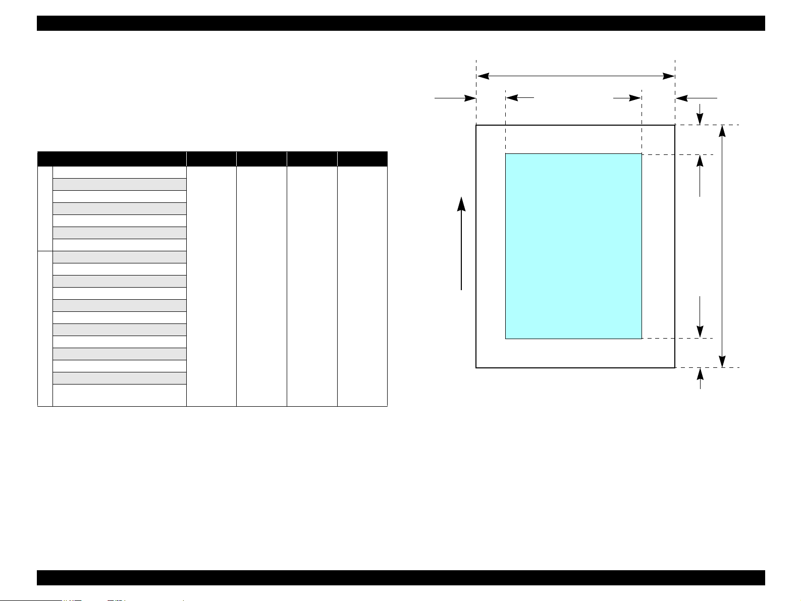
1.4.1.1 Printable Area
Cut sheet (standard printing)
Printable area
For paper width (PW) and paper length (PL), refer to 1.4.1 Paper Support
(p16).
Table 1-12. Applicable Paper/Printing Area
Paper type LM RM TM BM
A4
A5
A6
B5
Letter
Cut Sheet
Legal
User defined
Premium Inkjet Plain Paper
Bright White Ink Jet Paper
Photo Paper
Premium Glossy Photo Paper
Premium Semigloss Photo Paper
Matte Paper-Heavyweight
Double-sided Matte Paper
Economy Photo Paper
Photo Quality Ink Jet Paper
Exclusive papers
Glossy Photo Paper
Premium Glossy Photo Paper (RC-X)
Ultra Glossy Photo Paper
Ultra Premium Glossy Photo Paper
3 mm 3 mm 3 mm
12.5 mm/
*1
3 mm
PW
LM
Printable area
Paper Feed Direction
Figure 1-5. Printable Area for Cut Sheet (Standard Printing)
RM
TM
PL
BM
Note *: It is possible to set the margins for all sides to zero under the special conditions.
Note *1: Bottom margin is expanded to 3 mm when paper dimension is defined by using
command (ESC (S and Remote “SN”), otherwise it is not expanded (12.5 mm).
From a form lower end 3 mm as for 12.5 mm area a printing may scramble.
PRODUCT DESCRIPTION Paper 18
Page 19
EPSON Stylus C87/C88/D88 Revision A
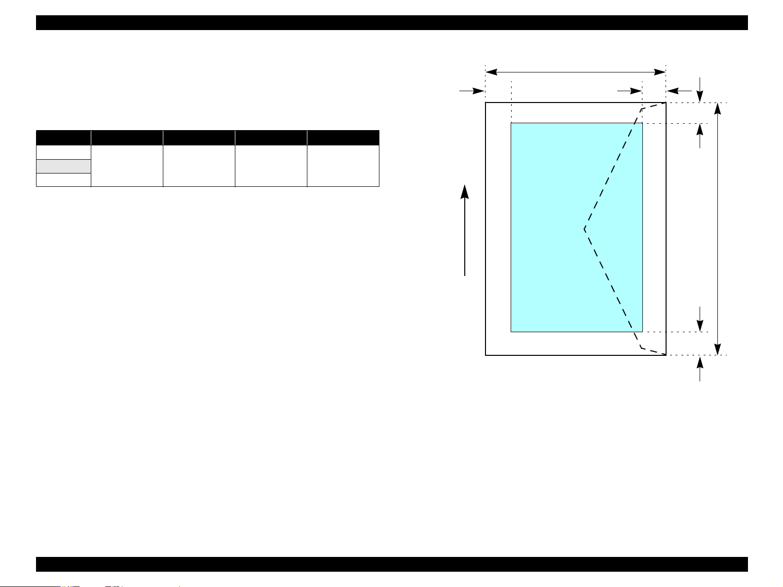
Envelopes
Printable area
For paper width (PW) and paper length (PL), refer to 1.4.1 Paper Support
(p16).
Table 1-13. Applicable Paper/Printing Area
Paper type LM RM TM BM
#10
3 mm 3 mm 3 mm 20 mmDL
C6
PW
LM
RM
TM
Printable area
PL
Paper Feed Direction
BM
Figure 1-6. Printable Area for Envelopes
PRODUCT DESCRIPTION Paper 19
Page 20

EPSON Stylus C87/C88/D88 Revision A
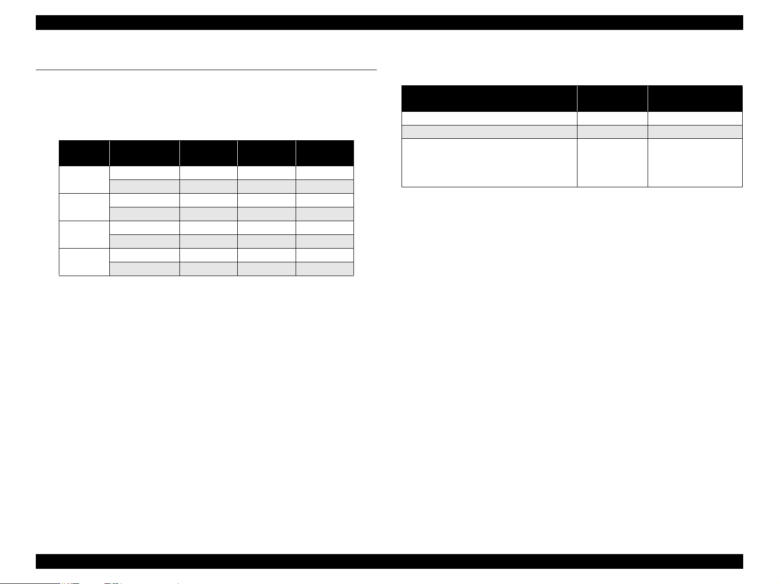
Cut sheet (border-free printing)
Printable area
For paper width (PW) and paper length (PL), refer to 1.4.1 Paper Support
(p16).
Table 1-14. Applicable Paper/Printing Area
Paper type Size LO RO TO BO
Photo Paper
Premium Glossy Photo Paper
Premium Semigloss Photo Paper
Matte Paper-Heavyweight
Exclusive papers
Double-sided Matte Paper
Economy Photo Paper A4 2.54 2.54 2.96 4.02
Glossy Photo Paper Letter 2.54 2.54 2.96 4.02
Premium Glossy Photo Paper (RC-X) 4” x 6” 2.54 2.54 1.34 2.54
Ultra Premium Glossy Photo Paper
Ultra Glossy Photo Paper
A4 2.54 2.54 2.96 4.02
4” x 6” 2.54 2.54 1.34 2.54
Letter 2.54 2.54 2.96 4.02
A4 2.54 2.54 2.96 4.02
8” x 10” 2.54 2.54 2.96 4.02
5” x 7” 2.54 2.54 2.96 4.02
4” x 6” 2.54 2.54 1.34 2.54
3R 2.54 2.54 1.34 2.54
Letter 2.54 2.54 2.96 4.02
A4 2.54 2.54 2.96 4.02
4” x 6” 2.54 2.54 1.34 2.54
Letter 2.54 2.54 2.96 4.02
A4 2.54 2.54 2.96 4.02
Letter 2.54 2.54 2.96 4.02
A4 2.54 2.54 2.96 4.02
Letter 2.54 2.54 2.96 4.02
A4 2.54 2.54 2.96 4.02
8” x 10” 2.54 2.54 2.96 4.02
5” x 7” 2.54 2.54 2.96 4.02
4” x 6” 2.54 2.54 1.34 2.54
LO ROPW
Paper size
Paper Feed Direction
Printable area
Figure 1-7. Printable Area for Cut Sheet (Border-free Printing)
TO
PL
BO
PRODUCT DESCRIPTION Paper 20
Page 21
EPSON Stylus C87/C88/D88 Revision A
1.5 Ink Cartridge
1.5.1 Ink Cartridge Specification
Type/Color: Separate ink cartridges for each color
Table 1-15. Ink Cartridge
Color Size EAI
Black
Cyan
Magenta
Yellow
Ink life:
Black ink cartridge
Print capacity
SS Size --- T0631 T0611
S Size T0601 T0621 T0641
SS Size --- T0632 T0612
S Size T0602 --- ---
SS Size --- T0633 T0613
S Size T0603 --- ---
SS Size --- T0634 T0614
S Size T0604 --- ---
S size: 430 pages /A4 (360 dpi, 5% duty each color)
SS size: 250 pages /A4 (360 dpi, 5% duty each color)
Latin/Asia/
Pac
EUR
Storage temperature
Table 1-16. Storage Temperature
Situation
When transported in individual boxes -30°C ~ 50°C Within 10 days at 50°C
When stored in individual boxes -30°C ~ 40°C Within 1 month at 40°C
When installed in main unit -20°C ~ 40°C Within 1 month at 40°C
Storage
temperature
Limit
Temperature difference
should be less than 45°C
in this period.
Color ink cartridge
Print capacity
S size: 470 pages /A4 (360 dpi, 5% duty each color)
SS size: 280 pages /A4 (360 dpi, 5% duty each color)
Expiration date: Two years
(include both the time interval that the ink cartridge is
unopened and the period after it is unpacked)
PRODUCT DESCRIPTION Ink Cartridge 21
Page 22

EPSON Stylus C87/C88/D88 Revision A
Dimension: 12.7 mm (W) x 73.46 mm (D) x 55.25 mm (H)
12.7mm
Base View
73.46mm
Figure 1-8. Ink Cartridge
C A U T I O N
Ink cartridge can not re-fill, only ink cartridge is prepared for
article of consumption.
Do not use the ink cartridge which has expired.
Ink will be frozen under -16 °C environment, however it will be
usable after placing it more than three hours at room
temperature.
PRODUCT DESCRIPTION Ink Cartridge 22
Page 23

OPERATING PRINCIPLES
CHAPTER
2
Page 24
EPSON Stylus C87/C88/D88 Revision A
2.1 Overview
This section describes the operating principles of the printer mechanism and electrical
circuit boards.
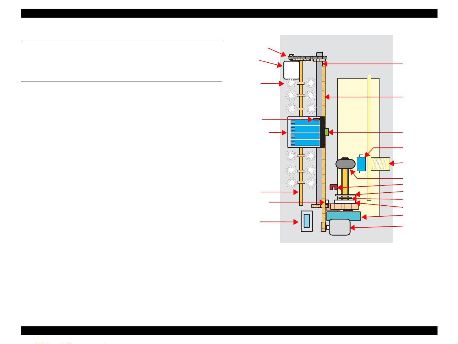
2.2 Printer Mechanism
Printer mechanism of Stylus C87/C88/D88 consists of printhead, carriage mechanism,
paper loading mechanism, paper feeding mechanism, and ink system.
As in the case of conventional models, Stylus C87/C88/D88 has two DC motors; one is
for paper loading/feeding mechanism and the pump mechanism, and the other is for
carriage mechanism.
Papers are fed from the backside and ejected from the front side of the printer.
Paper feeding mechanism, which is also similar to conventional models, feeds papers
using the LD roller and the retard roller.
PF timing belt
PF motor
Star wheel
rollers
PW sensor
Carriage unit
Paper eject
roller
Change lever
Cap unit
PF roller
CR timing belt
CR encoder
sensor
Retard roller
Compression
spring
LD roller
PE sensor
Cam, large
Cam, small
Clutch
Pump unit
CR motor
Figure 2-1. Printer Mechanism Outline
OPERATING PRINCIPLES Overview 24
Page 25
EPSON Stylus C87/C88/D88 Revision A
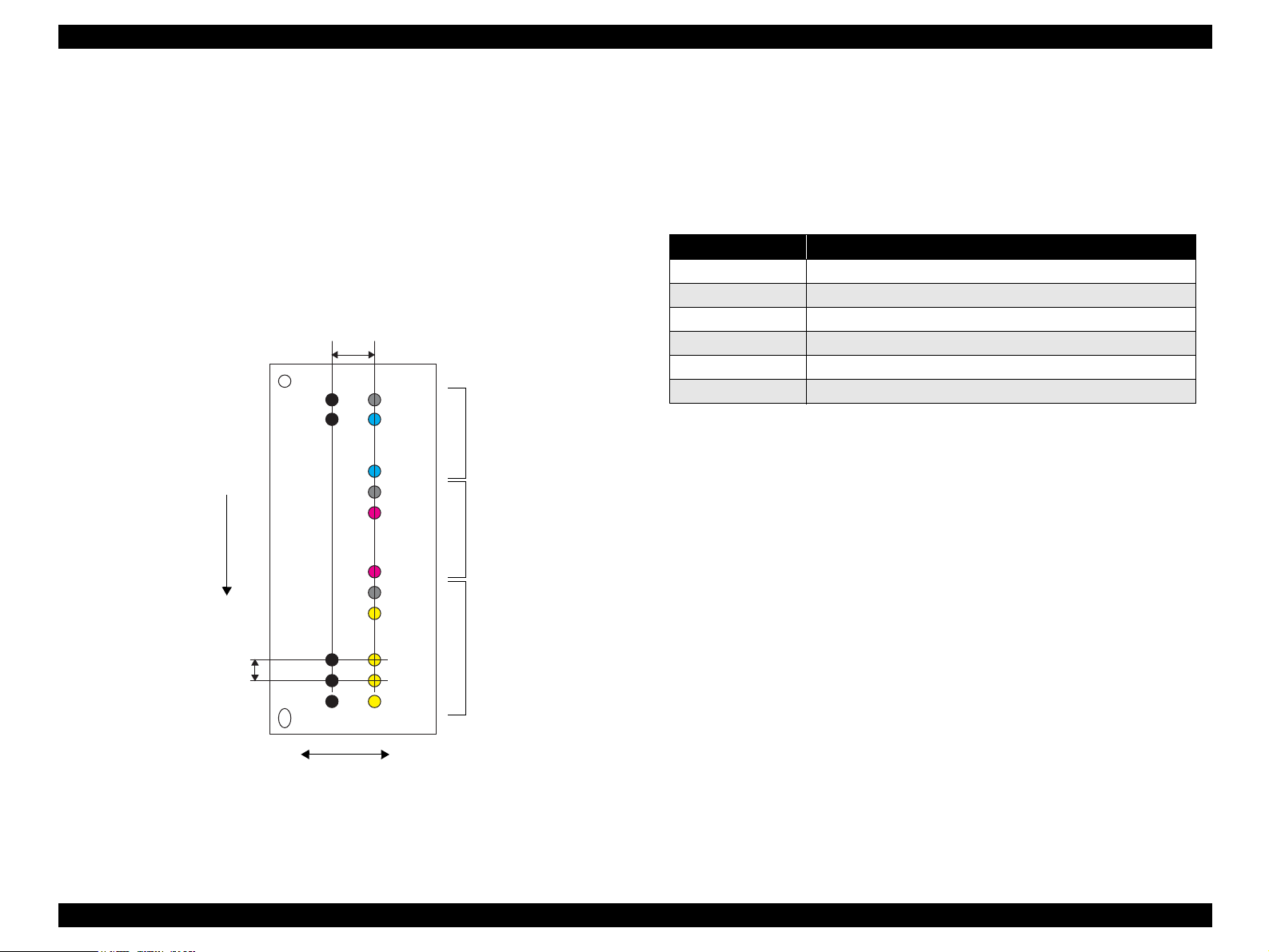
2.2.1 Printhead Specifications
This printer employs P-Match type printhead, which enables the product to perform
both the variable dot printing and the economy dot printing.
Nozzle configuration
Monochrome: 180 nozzles
Color: 59 nozzles x 3 rows/color (Cyan, Magenta, Yellow)
The following shows the arrangement of the nozzles and the color arrangement of each
nozzle line when viewed the printhead from behind.
2.258mm
(32/360 inch)
C#60K#180
K#179
Paper Loading Direction
C#59
Cyan: 59nozzles
C#1
M#60
M#59
Magenta: 59nozzles
2.2.2 Carriage Mechanism
Main components of the carriage mechanism are carriage unit (including printhead,
CR encoder sensor, PW sensor), CR motor, timing belt, and CR scale.
2.2.2.1 CR Motor Specifications
Table 2-1. CR Motor Specifications
Item
Type Motor with DC brush
Drive voltage +42 V ± 5% (applied voltage to the driver)
Electric resistance 22.65 Ω ± 10%
Inductance 17.3 mH ± 25%
Drive method PWM, constant-current chopping
Drive IC A6615
Specification
M#1
Color
Y#60
Y#59
Y#3
Y#2
Y#1
Yellow: 59nozzles
0.1411mm
(1/180 inch)
Black
K#3
K#2
K#1
Carriage Moving Direction
Figure 2-2. Nozzle Rear View
NOTE: #60 nozzles of each color are not used for printing, but for flushing.
OPERATING PRINCIPLES Printer Mechanism 25
Page 26

EPSON Stylus C87/C88/D88 Revision A
2.2.3 Paper Loading/Feeding Mechanism
Paper loading/feeding mechanism consist of switching lever inside the ink system,
holder shaft unit (including clutch mechanism), and ASF unit.
Switching lever and clutch mechanism play an important role in paper loading
mechanism. Refer to 2.2.3.2 Drive Process (p26) for details.
2.2.3.1 PF Motor Specifications (For both ASF and Pump motor)
Table 2-2. PF Motor Specification
Item Specification
Type 4-phase, 200-pole HB stepping motor
Drive voltage +42 V ± 5 % (applied voltage to the driver)
Wire wound
resistance
Inductance 3.5 mH ± 20% (1KH, 1Vrms)
Drive method
Drive IC A6628
2-2 phase, 1-2 phase, W1-2, 2W1-2, 4W1-2 phase constant-current drive
3.0 Ω ± 10% (per one phase at 25 °C)
Bipolar drive
2.2.3.2 Drive Process
1. Drive of the PF motor is transmitted to the paper eject roller and the PF roller via
the PF timing belt, however, it is not transmitted to the LD roller and the retard
roller owing to the clutch of the holder shaft unit.
2. The carriage unit moves to the ASF trigger position once the paper loading
command is received.
3. PF motor is rotated counter clockwise, and the clutch is released by the change
lever.
4. After the clutch is released, the PF motor rotates clockwise. Drive is transmitted to
the LD roller and the paper loading operation begins.
5. During paper loading operation, papers are fed from the ASF unit to inside the
printer by the rotating movement of the two cams of the LD roller.
Cam, large: releases hopper
Cam, small: releases paper back lever
6. Once a sheet of paper is fed, the hopper and the paper back lever bring back rest of
the papers to the position in readiness by the rotating movement of the two cams
mentioned above.
7. When the LD roller is turned a full circle, the change lever release the clutch and
the drive to the LD roller is interfered.
OPERATING PRINCIPLES Printer Mechanism 26
Page 27

EPSON Stylus C87/C88/D88 Revision A
2.2.4 Ink System Mechanism
The Ink system mechanism consists of pump mechanism and capping mechanism with
wiper mechanism.
2.2.4.1 Pump Unit Mechanism
The PF motor is a source of power to activate the pump unit.
Table 2-3. PF Motor Rotational Direction & Ink System Mechanism
Directions
Counterclockwise
Clockwise
Note *: The PF Motor rotational direction = seen from the left side of the printer.
2.2.4.2 Capping Mechanism
The Capping mechanism covers the printhead with the cap to prevent the nozzle from
increasing viscosity when the printer is in stand-by state or when the printer is off.
*
• Absorbs the ink by the Pump Unit
• Release pump.
Functions
2.3 Electrical Circuit Operating Principles
The electric circuit of the Stylus C87/C88/D88 consists of the following boards.
Main board: C528 MAIN Board
Power supply board: C528 PSB/PSB board
Panel board: C528 PNL board
This section provides block diagram of both C528 MAIN Board and C528 PSB/PSE
Board,C528 PNL board.
C528 PNL Board
Printer Mechanism
CR Motor
PF Motor
C528 Main Board
Head Driver Board
Sensors
CSIC Unit
+42V
C528 PSB/C528 PSE Board
Figure 2-3. Electrical Circuit Block Diagram
PowerOFF
OPERATING PRINCIPLES Electrical Circuit Operating Principles 27
Page 28

EPSON Stylus C87/C88/D88 Revision A
2.3.1 C528 PSH Board
PSH board of Stylus C87/C88/D88 employs ZC-RRC circuit method, and supplies +42
VDC/+5VDC to the drive line.
AC voltage input from AC inlet first goes through filter circuit that removes high
frequency components and is then converted to DC voltage via the rectifier circuit and
the smoothing circuit.
2.3.2 C528 Main Board
The logic circuit of the C528 Main Board is composed of the following;
Logic line (CPU-ASIC 4 in 1, DRAM and so on)
Motor control/drive circuit (CR Motor, PF Motor)
Head control/drive circuit
Parallel interface control circuit
Sensor circuit
Reset circuit
EEPROM circuit
Table 2-4. C528 MAIN Board Major Components and Primary Functions
IC Location Function
Parallel I/F
Controller
Reset Regulator IC1
DRAM IC8
EEPROM IC4 Makes back up of default setting values and parameters.
Motor Driver IC6
Head Driver IC7 Generates trapezoidal waveform, drives 42 V.
ASIC IC10
Transceiver for centronics IF that responds to IEEE1284 and ECP
IC2
or more, data transfer, and 3.3 V drive.
Reset signal is generated under the following conditions.
• Pressure reduction from 42 V line to 35.8 V.
• Pressure reduction from 5 V line to 4.2 V line.
16 Mbit DRAM with 2 CAS-type page access function.
3.3 V drive.
Drives CR/PF motors, controls PWM by the program timer, drives
42 V.
Drives CPU (H8S/2323 base), internal 8 K bit RAM, internal
MASK ROM, 24 Mhz, 3.3 V drive.
Figure 2-4. C528 Main Board Block Diagram
OPERATING PRINCIPLES Electrical Circuit Operating Principles 28
Page 29

TROUBLESHOOTING
ICHAPTER
3
Page 30

EPSON Stylus C87/C88/D88 Revision A
3.1 Overview
This chapter describes how to solve problems.
W A R N I N G
C H E C K
P O I N T
Be careful to avoid electric shocks when checking the electrical
circuit boards (C528 MAIN and C528 PSE boards) while the
power is turned on.
Touching an FET, transistor or heat sink with one hand while
touching a metal part of the mechanism with the other hand
could result in an electric shock, so carefully avoid this.
After initial filling of ink has been repeated several times,
immediate moving or tilting of the printer could result in
leaking of ink that has not been completely absorbed by the
Waste Ink Pad. When initial filling of ink has been repeated
several times, check the ink remaining in the tip of the Waste
Ink Tube and the waste ink not absorbed by the Waste Ink Pad
before moving the printer.
Disassembly and reassembly of parts is often required when
identifying the causes of problems. The parts should be
disassembled and re-assembled correctly while referring to
Chapter 4 “DISASSEMBLY/ASSEMBLY” (p.36) so that the
operation and status of each check item can be correctly
verified.
Some individual part and units may require adjustment once
they are removed or replaced. If removing or replacing parts
which have specific instructions for adjustment included in
Chapter 4 “DISASSEMBLY/ASSEMBLY” (p.36), be sure to
make these adjustments after repairing the problem location.
3.1.2 Preliminary Checks
Before starting troubleshooting, be sure to verify that the following conditions
are all met:
The power supply voltage must be within the specification limits. (Measure the
voltage at the wall socket.)
The power code must be free from damage, short circuit or breakage, or miswiring
in the power code.
The printer must be grounded properly.
The printer should not be located in a place where it can be exposed to too high or
low temperature, too high or low humidity, or abrupt temperature change.
The printer should not be located near waterworks, near humidifiers, near heaters
or near flames, in a dusty atmosphere or in a place where the printer can be
exposed to blast from an air conditioner.
The printer should not be located in a place where volatile or inflammable gases
are produced.
The printer should not be located in a place where it can be exposed to direct rays
of the sun.
The printer must be located in a well-ventilated place.
The printer must be placed on a strong and steady level table (without an
inclination larger than five degrees).
The paper used must conform to the specification.
There is no error in handling of the printer.
Check the inside of the printer, and remove foreign matters if any, such as paper
clips, staples, bits of paper, paper dust or toner.
3.1.1 Specified Tools
This printer does not require any specified tools for troubleshooting.
Clean the inside of the printer and the rubber rolls.
TROUBLESHOOTING Overview 30
Page 31

EPSON Stylus C87/C88/D88 Revision A
3.2 Troubleshooting With LED Error Indications
LED error display, cause, and remedy are explained here.
Table 3-1. Troubleshooting With LED Error Indications
Error
Ink end/ No ink cartridge/
CSIC error
Paper Out
Multi-feed error
Power Paper Ink
--- --- On
--- On ---
--- On ---
LED status
Cause Remedy
• Ink inside Bk, Y, M, C ink cartridges has run out.
• Ink cartridge(s) is not installed.
• Non-genuine ink cartridge(s) is installed.
• Paper loading operation is executed when there is no paper.
• Papers stopped before the PE Sensor or could not be fed.
• Papers are fed without being placed against the right edge
guide.
• Connector of the PE sensor is disconnected.
• When performing duplex printing, blank paper is ejected.
• The printer detected that the paper is too long upon ejection.
• Check the ink cartridge(s) and reinstall it correctly.
• Replace the ink cartridge(s) with a genuine one.
• If there is a possibility of CSIC error, see
3.3 Troubleshooting for Motors and Sensors (p35).
1. If there is no paper on the paper tray, load papers.
2. If the paper has stopped halfway, remove the paper,
check if the paper is not bent, fan the paper, and load
it against the edge guide.
3. Press the [Paper] switch to release the error.
1. Remove the blank paper, or check the paper size.
2. Press the [Paper] switch to eject the paper and release
the error.
TROUBLESHOOTING Troubleshooting With LED Error Indications 31
Page 32

EPSON Stylus C87/C88/D88 Revision A
Table 3-1. Troubleshooting With LED Error Indications
Error
Paper jam
Maintenance request
(Waste ink overflow)
Fatal error
Power Paper Ink
--- Flashes ---
Off
Off
LED status
Flashes
alternately
Flashes on
high speed
Flashes
alternately
Flashes on
high speed
Cause Remedy
Even though paper feeding operation is carried out for
predetermined times, leading edge or back-end of the paper
could not be detected.
As a result of cleaning and flushing, total emission of ink has
exceeded the specific level.
• Home position of the carriage could not be detected.
• Abnormal external pressure is applied to the printer when
the power is on.
• Carriage movement is interfered during printing.
1. Press the [Paper] switch on the panel.
2. If paper jam occurred again after pressing the switch,
open the printer cover and remove all the papers
inside the printer and papers set on the hopper.
3. Making sure there is no paper inside the printer, load
paper on the hopper and press [Paper].
Replace the waste ink pad, and reset the waste ink
counter (protection counter A) using the adjustment
program. Refer to Chapter 6 “MAINTENANCE”
(p.92) for details.
1. Turn the power off, wait for a few seconds, and turn
the power back on again.
2. If the fatal error still appears, turn the power off,
remove the papers on the hopper, and check the
following:
• Open the printer cover, check the ink cartridges, and
reinstall them correctly.
• Check is there is no foreign material or papers inside
the printer. If there is any, remove them.
3. Turn the printer power on.
4. If the fatal error appears again, refer to 3.2.1 Fatal
Error (p33) and examine/replace the parts.
TROUBLESHOOTING Troubleshooting With LED Error Indications 32
Page 33

EPSON Stylus C87/C88/D88 Revision A
3.2.1 Fatal Error
C H E C K
P O I N T
As the most recent fatal error (fatal error code) is stored in the
EEPROM (Address: 0AH), it is possible to check the error by using
the adjustment program.
Check the parts according to the contents of the fatal error, and replace the parts as necessary.
Classification Item Description Remedy
DC Error PID aveTi max Error Something is wrong with the CR motor. Check the parts listed below, and replace them as necessary.
PID Overspeed Error Carriage movement speed is abnormal.
PID Lock Error Carriage has been locked for a certain period of time due to
PID Reverse Rotation Detection Error The number of the carriage reverse rotation has exceeded the
Encoder Abnormality Error (CR Driving
Time Over Error)
Load Positioning Overspeed Error Abnormal carriage movement speed is detected during load
Load Positioning Lock Error It is detected that the carriage has been locked for a certain
Load Positioning Cumulative Movement
Distance Error
Head Error Transistor Environment Temperature
Abnormality Error
Pre-printing X-HOT Detection Error During pre-printing X-Hot detection, the temperature of the
Post-flushing X-HOT Detection Error During post-printing X-Hot detection, the temperature of the
external factors.
predetermined times due to external factors.
One-pass movement cannot be completed though the CR
motor has been driving longer than the specified time.
positioning control.
period of time during load positioning control.
The cumulative movement distance during the load
positioning control has exceeded the given level
The environment temperature of the transistor that generates
head driving waveform on the Main board is abnormal.
head driver IC has exceeded the given level for more than two
seconds.
head driver IC has exceeded the given level for more than two
seconds.
• CR Motor
• CR Encoder
• CR Encoder Scale
• Timing Belt
•Main Board
• Connectors and harnesses of each motor or encoder
Check the parts listed below, and replace them as necessary.
• Printhead
• Head FFC
•Main Board
TROUBLESHOOTING Troubleshooting With LED Error Indications 33
Page 34

EPSON Stylus C87/C88/D88 Revision A
Classification Item Description Remedy
Sequence Error Left Frame Shock Detection Error Abnormal pressure has being added to the carriage due to
Between Left Frame and [TF] Shock
Detection Error
Between [TF] and [HOME] Shock
Detection Error
external factors.
Make sure that there is no obstruction on the carriage moving
path, check the parts listed below, and replace them as necessary.
• CR Motor
• CR Encoder
• CR Encoder Scale
• Timing Belt
•Main Board
TROUBLESHOOTING Troubleshooting With LED Error Indications 34
Page 35

EPSON Stylus C87/C88/D88 Revision A
3.3 Troubleshooting for Motors and Sensors
Motor
Table 3-2. Motor Resistance and Check Points
Motor name Type Location
CR motor Motor with DC brush CN5 Pin 1&3 22.65 Ω ± 10%
PF motor 4-phase, 200-pole HB stepping
motor
CN6 Pin 1&3
Check
point
Pin 2&4
Resistance
3.0 Ω ± 10%
Sensor
Table 3-3. Sensor Check
Sensor name Detecting system Location Signal level Sensor status
PE sensor Transmission photo
interrupter
PW sensor Reflective photo
interrupter
CN9 pin 1&2 2.4 V or more Paper loaded
0.4 V or less No paper
T.B.D Low Low: Paper loaded
High High: No paper
TROUBLESHOOTING Troubleshooting for Motors and Sensors 35
Page 36

DISASSEMBLY/ASSEMBLY
CHAPTER
4
Page 37

EPSON Stylus C87/C88/D88 Revision A
4.1 Overview
This section describes procedures for disassembling the main components of the
product. Unless otherwise specified, disassembled units or components can be
reassembled by reversing the disassembly procedure.
Procedures which, if not strictly observed, could result in personal injury are described
under the heading “WARNING”.
“CAUTION” signals a precaution which, if ignored, could result in damage to
equipment.
Important tips for procedures are described under the heading “CHECK POINT”.
If the assembly procedure is different from the reversed disassembly procedure, the
correct procedure is described under the heading “REASSEMBLY”.
Any adjustments required after reassembly of components or parts are described under
the heading “ADJUSTMENT REQUIRED”.
When you have to remove any components or parts that are not described in this
chapter, refer to the exploded diagrams in the appendix.
4.1.1 Precautions
See the precautions given under the handling “WARNING” and “CAUTION” in the
following columns when disassembling or assembling EPSON Stylus C87/C88/D88.
W A R N I N G
Disconnect the power cable before disassembling or assembling
the printer. If you need to work on the printer with power
applied, strictly follow the instructions in this manual.
Always wear gloves for disassembly and reassembly to avoid
injury from sharp metal edges.
To protect sensitive microprocessors and circuitry, use static
discharge equipment, such as anti-static wrist straps, when
accessing internal components.
C A U T I O N
Make sure that there is enough work space for disassembly/
reassembly.
Use only recommended tools for disassembling, assembling or
adjusting the printer.
Observe the specified torque when tightening screws.
Apply lubricants as specified.
(See Chapter 6 “Lubrication” (p.95) for details.)
The pictures of the product in this manual are of prototype
model. There may be differences in configurations or colors
compared to the actual model, however, it has no effect on
dissasembly/assembly.
When using compressed air products; such as air duster, for
cleaning during repair and maintenance, the use of such
products containing flammable gas is prohibited.
4.1.2 Tools
Use only specified tools to avoid damaging the printer.
Table 4-1. Tools
Name Supplier Parts No.
(+) Phillips screwdriver #0
(+) Phillips screwdriver #1
Flathead screwdriver
Tweezer
Longnose pilers
Hexagonal Box Driver [B741700100]
EPSON 1080531
EPSON 1080530
EPSON 1080527
EPSON 1080561
EPSON 1080564
EPSON
1080584
DISASSEMBLY/ASSEMBLY Overview 37
Page 38

EPSON Stylus C87/C88/D88 Revision A
4.1.3 Screws (T.B.D)
Screws used on the Stylus C87/C88/D88 are shown below.
Table 4-2. Screws
No. Image Name Type
C.B.S. 3 x 6 C.B.S-TITE SCREW
1
C.B.S. 3x 10 C.B.S-TITE SCREW
2
C.B.S. 3 x 14 C.B.S-TITE SCREW
3
C.B.S.(P4) 3 x 6 C.B.S-TITE (P4) SCREW
4
C.B.P. 2.5 x 8 C.B.P-TITE SCREW
5
Table 4-2. Screws
No. Image Name Type
C.P. 3 x 4 C.P. SCREW
8
C.P.B. (P1) 1.7 x 5 T.B.D
9
Hexagon nut, normal, M3 T.B.D
10
C.B.P. 3 x 8 C.B.P-TITE SCREW
6
C.B.P. (P2) 3 x 8 C.B.P-TITE (P2) SCREW
7
DISASSEMBLY/ASSEMBLY Overview 38
Page 39

EPSON Stylus C87/C88/D88 Revision A
4.1.4 Work Completion Check
If any service is made to the printer, use the checklist shown below to confirm all
works are completed properly and the printer is ready to be returned to the user.
Table 4-3. Work Completion Check
Classification Item Check Point Status
Checked
Not necessary
Checked
Not necessary
Checked
Not necessary
Checked
Not necessary
Checked
Not necessary
Checked
Not necessary
Checked
Not necessary
Checked
Not necessary
Checked
Not necessary
Checked
Not necessary
Checked
Not necessary
Checked
Not necessary
Checked
Not necessary
Main Unit
Adjustment
Lubrication
Self-test Is the operation normal?
ON-line Test Is the printing successful
Printhead
Carriage
Mechanism
Paper Feeding
Mchanism
Specified
Adjustment
Specified
Lubrication
Is ink discharged normally from all
the nozzles?
Does it move smoothly?
Is there any abnormal noise during its
operation?
Is there any dirt or foreign objects on
the CR Guide Shaft?
Is the CR Motor at the correct
temperature? (Not too hot to touch?)
Is paper advanced smoothly?
No paper jamming?
No paper skew?
No multiple feeding?
No abnormal noise?
Is the PF Motor at correct
temperature?
Is the paper path free of any
obstructions?
Are all the adjustment done correctly?
Are all the lubrication made at the
specified points?
Is the amount of lubrication correct?
Table 4-3. Work Completion Check
Classification Item Check Point Status
Function ROM Version Version:
Are the ink cartridges installed
correctly?
Have all relevant protective materials
been attached to the printer?
Have all the relevant items been
included in the package?
Packing
Others
Ink Cartridge
Protective
materials
Attachments,
Accessories
Checked
Not necessary
Checked
Not necessary
Checked
Not necessary
Checked
Not necessary
DISASSEMBLY/ASSEMBLY Overview 39
Page 40

EPSON Stylus C87/C88/D88 Revision A
4.2 Caution regarding Assembling/Disassembling
of the Printer Mechanism, and How to Ensure of
Quality on Re-assembled Product
On current low end models, we’ve basically forbidden to remove Housing, Lower from
Printer mechanism in your repair. This is because there is a possibility of main frame
deformation when a part (such as Ink system) is removed from Printer mechanism
without Housing, Lower.
For this reason, if you want to replace Ink system/PF motor, we recommend to replace
with new Printer mechanism with Housing, Lower. On these models, you have to
remove Housing, Lower from printer mechanism when replacing Waste Ink Pad with a
new one.
Therefore, we clarify caution regarding assembling/disassembling of the printer
mechanism without Housing, Lower, and how to ensure of quality on repaired products
in this section.
[Caution regarding assembling/disassembling of the printer mechanism]
1) Main frame
(a) Control of assembled standard position.
[Reason]
The assembled accuracy of each part composed of Printer mechanism is based
on Housing, Lower.
[Service treatment]
Confirm that there is no gap between main frame and Housing, Lower.
[Reference]
To ensure the assembled accuracy, you have to control the assembled
standard position of main frame against X/Y/Z-axis direction.
[X-axis direction]
- Make sure that main frame is correctly placed on the groove of Housing,
Lower.
- Make sure that there is no gap between main frame and Housing, Lower.
[Y-axis direction]
Make sure that cut-out portion of main frame is correctly placed on the square
protrusion of Housing, Lower.
[Z-axis direction]
- Make sure that there is no gap between main frame and Housing, Lower.
- Make sure that the left side of Printer mechanism is correctly fixed by two
tabs.
(b) Control of vertical level of guide rail (Guide rail means the portion latched by
hooks of IC holder & Print head assy.)
[Reason]
There is a possibility that printing failure/operation failure occurs by guide
rail deformation.
[Service treatment]
- Do not remove [Mounting Plate, M/B] from Printer mechanism.
- Hold up the specified position of main frame to avoid the deformation.
(c) How to assemble of ASF unit/Circuit board/Paper guide upper
[Reason]
There is a possibility that main frame deformation is caused extra force in
assembling. As the result, printing failure/operation failure occurs.
[Service treatment]
Hold the opposite side with hand while you are installing the above parts.
DISASSEMBLY/ASSEMBLY Caution regarding Assembling/Disassembling of the Printer Mechanism, and How to Ensure of Quality on Re-assembled
Page 41

EPSON Stylus C87/C88/D88 Revision A
2) Front frame
(a) Control of vertical level
[Reason]
There is a possibility that printing failure occurs by front frame deformation.
[Service treatment]
Handle Front frame in assembling/disassembling carefully.
3) IC holder
(a) Handling of IC holder
[Reason]
If IC holder is damaged in assembling/disassembling of your repair, there is a
possibility that vital problem occurs in user’s further operation.
[Service treatment]
Released two hooks of IC holder from the inside of IC holder by the tweezer.
[How to ensure of quality on re-assembled product]
We judge that the quality of re-assembled product is ensured if there is no
problem about the print result by adjustment program.
DISASSEMBLY/ASSEMBLY Caution regarding Assembling/Disassembling of the Printer Mechanism, and How to Ensure of Quality on Re-assembled
Page 42

EPSON Stylus C87/C88/D88 Revision A
4.3 Dissasembly Procedures
This section explains the procedures for disassembling the product.
Unless otherwise stated, reassembly should be carried out in the reverse order of the disassembly procedure.
For detailed engagement relations among main components, refer to the exploded diagrams in the Appendix.
When disassembling each unit, refer to the pages described in the chart below.
START
“ Housing, Left (p44)”
“ Stacker Assy. (p47)”
“ Housing, Upper Assy
(p47)”
“ ASF Unit (p48)”
“ Housing, Right (p45)”
“ CR Timing Belt (p66)”
“ CR Motor (p67)”
“ Front Frame (p68)”
“ Eject Roller (p75)”
“ Paper Guide, Front Assy.
(p76)”
“ CR Encoder
Scale (p69)”
“ CR Cable Head Cover
(p70)”
“ Paper Guide, Upper
Assy. (p75)”
Figure 4-1. Disassembling Flowchart (1)
DISASSEMBLY/ASSEMBLY Dissasembly Procedures 42
Page 43

EPSON Stylus C87/C88/D88 Revision A
* Procedure in the broken-line is NOT the shortest
START
“ ASF Unit (p48)”
removing procedure, but the passing point for the
next removing procedure.
“ Hopper/Retard Roller
Unit (p49)”
“ Holder Shaft Unit
(p62)”
“ Main Board (p57)”
“ PS Board (p61)”
“ Front Frame (p68)”
“ Eject Roller (p75)”
“ Paper Guide, Front Assy.
(p76)”
“ Housing, Lower Assy.
(p51)”
“ Waste Ink Pad (p55)”
“ Panel Board (p60)”
“ Holder Shaft Unit
(p62)”
“ Spool Gear 36.8/Extension
Spring 0.143/Clutch (p64)”
“ PE Sensor Board/PE
Detection Lever/Idle Roller
(p65)”
“ Printhead Assy. (p72)”
“ PF Motor (p79)”
“ Front Frame (p68)”
“ CR Encoder Scale (p69)”
“ CR Cable Head Cover
(p70)”
“ CR Unit (p70)”
“ PW Sensor Board
(p73)”
“ CR Encoder Sensor
Board (p73)”
“ CSIC Board (p74)”
“ Pump Unit/Cap Unit
(p78)”
Figure 4-2. Disassembling Procedure (2)
DISASSEMBLY/ASSEMBLY Dissasembly Procedures 43
Page 44

EPSON Stylus C87/C88/D88 Revision A
4.3.1 Removing Housings
C A U T I O N
4.3.1.1 Housing, Left
1) Insert a ruler or a similar tool to the notch on the bottom of the main unit to
Do not damage the tabs in removing the Housings.
Do not tilt the printer too much when removing the Housings
because ink may flow if the Carriage unit is not at the home
position.
release the tab of the I/F cover, and remove the I/F cover.
Bottom
Convex Portion
Housing, Right
Notch
Tab and Stopper
2) Insert a flathead driver or a similar tool to the notch on the backside of the
main unit, and release the tab.
Backside
Tab and Notch
Figure 4-4. Removing Housing, Left (2)
Inside
I/F Cover
Tab
Notch
Figure 4-3. Removing Housing, Left (1)
DISASSEMBLY/ASSEMBLY Dissasembly Procedures 44
Page 45

EPSON Stylus C87/C88/D88 Revision A
3) Release the tab on the bottom of the main unit from the stopper.
4) Open the cover of the Housing, Upper Assy, release the two tabs, and remove the Housing, Left.
Cover
Opening
Housing, Left
Tabs
Inside
Tabs
Notch
4.3.1.2 Housing, Right
1) Insert a flathead screwdriver or a similar tool to the notch on the backside of
the main unit, and release the tab.
Backside
Housing, Right
Tab and Notch
Figure 4-6. Removing Housing, Right (1)
2) Release the two tabs on the bottom of the main unit from the stopper.
Bottom
Notch
Tab
Tab and Stopper
Figure 4-7. Removing Housing, Right (2)
Figure 4-5. Removing Housing, Left (3)
3) Open the cover of the Housing, Upper Assy.
DISASSEMBLY/ASSEMBLY Dissasembly Procedures 45
Page 46

EPSON Stylus C87/C88/D88 Revision A
4) Press the CR lock lever to the rear of the main unit to release the lock, and
move the CR unit to the center of the printer.
CR Unit
CR Lock Lever
Figure 4-8. Releasing CR Lock Lever
5) Release the two tabs and remove the Housing, Right.
Cover
Opening
Housing, Right
Tabs
Inside
Notch
Tabs
Tabs
Figure 4-9. Removing Housing, Right (3)
DISASSEMBLY/ASSEMBLY Dissasembly Procedures 46
Page 47

EPSON Stylus C87/C88/D88 Revision A
4.3.1.3 Stacker Assy.
1) Remove the Housing, Left. (p44)
2) Open the Stacker Assy.
3) Push the shaft located on the left side of the Stacker Assy. with a flathead
screwdriver or a similar tool, release the shaft from the slot of the Housing,
Lower, and remove the Stacker Assy.
Stacker Assy.
4.3.1.4 Housing, Upper Assy
1) Remove the Housing, Right. (p45)
2) Remove the Stacker Assy.. (p47)
3) Release the two tabs on the front side of the main unit.
Front Side
Figure 4-11. Removing Housing, Upper Assy. (1)
4) Insert a flathead screwdriver or a similar tool to the notch on the backside of
the main unit, release the three tabs, and remove the Housing, Upper Assy.
Housing, Upper Assy.
Tab
Rear Side
Shaft
Notch and Tab
Figure 4-10. Removing Stacker Assy.
Figure 4-12. Removing Housing, Upper Assy. (2)
DISASSEMBLY/ASSEMBLY Dissasembly Procedures 47
Page 48

EPSON Stylus C87/C88/D88 Revision A
4.3.1.5 ASF Unit
1) Remove the Housing, Upper Assy. (p47)
2) Remove the three screws that secure the ASF Unit to the main unit, and remove the ASF unit.
• C.B.S. 3 x 6: 1
• C.B.S. (P4) 3 x 6 1
• C.B.P. 3 x 8: 1
Rear Side
3
ASF Unit
1
When installing the ASF Unit to the main unit, follow the steps
described below.
1. Make sure to match the shaft of the ASF Unit with the bearing of the Pump Unit.
2. Make sure to match the guide pin of the ASF Unit with the positioning hole of the main unit.
3. Secure the screws in the order shown in Figure 4-13.
Guide Pin
2
Shaft
Side of ASF Unit
C.B.P. 3 x 8
(6
±1 kgf.cm )
C.B.S. 3 x 6
(8
±1 kgf.cm)
C.B.S. ( P4) 3 x 6
(8
±1 kgf.cm )
Positioning Hole
and Guide Pin
Shaft and Bearing
Figure 4-14. Installing ASF Unit
Figure 4-13. Removing ASF Unit
DISASSEMBLY/ASSEMBLY Dissasembly Procedures 48
Page 49

EPSON Stylus C87/C88/D88 Revision A
A D J U S T M E N T
R E Q U I R E D
When I/C Holder or Printhead Assy. is removed or replaced
with a new one, the following adjustment must be performed in
the order below.
1) Top Margin Adjustment
2) First Dot Adjustment
3) PF Adjustment
When you replace the ASF unit with a new one, lubricate it as
specified. See Chapter 6 “Lubrication” (p.95) for details.
4.3.1.6 Hopper/Retard Roller Unit
C A U T I O N
1) Remove the ASF Unit. (p48)
2) Lift up the Hopper toward the direction of the arrow, release the two tabs, and
Hopper Side
Do not touch the cork on the Retard Roller and the Hopper.
remove the spring and the hopper from the ASF Frame.
ASF Frame Side
Tab
Shaft
Cork
Hopper
Spring
Retard Roller
Figure 4-15. Removing Hopper
DISASSEMBLY/ASSEMBLY Dissasembly Procedures 49
Page 50

EPSON Stylus C87/C88/D88 Revision A
3) Remove Extension Spring 0.585 from both the ASF Frame and the Paper Back Lever.
4) Remove the Paper Back Lever from the bearing of the ASF frame.
5) Remove Compression Spring 1.88 from the ASF Frame, and remove the Retard Roller Unit.
Extension
Spring 0.585
Compression
Spring 1.88
Paper Back
Lever
ASF Frame
Bearing
When installing the Retard Roller or the Paper Back Lever,
attach the two springs as described below.
• Extension Spring 0.585
Attach the spring to the tab of the ASF Frame and the one
of the Paper Back Lever.
• Compression Spring 1.88
Attach the spring to the boss of the ASF Frame and the one
of the Retard Roller Unit.
Tab
Extension Spring 0.585
Tab
Compression
Spring 1.88
Boss
Figure 4-17. Assembling ASF Frame(1)
When installing the spring between the Hopper and the ASF
Frame, match the spring with the positioning hole (circular
dent) of the Hopper and the one of the ASF Frame.
Retard Roller Unit
Hopper Side
ASF Frame Side
Figure 4-16. Removing Retard Roller Unit
Positioning Hole
Positioning Hole
Figure 4-18. Assembling ASF Frame (2)
DISASSEMBLY/ASSEMBLY Dissasembly Procedures 50
Page 51

EPSON Stylus C87/C88/D88 Revision A
4.3.1.7 Housing, Lower Assy.
C A U T I O N
1) Remove the Paper Guide, Front Assy.. (p76)
2) Peel and remove the Right Frame Sheet from the printer mechanism.
Do not remove the Housing, Lower Assy. more than is necessary.
Right Frame Sheet
Double-sided
Tape Location
3) Remove the two rubber feet on the PF Motor side.
Rubber Feet
Figure 4-20. Removing Rubber Feet
C A U T I O N
When removing the Waste Ink Tube from the Waste Ink Pad, pay
attention not to spill the ink.
4) Remove the Waste Ink tube from both the groove of the Housing, Lower Assy and the Waste Ink Pad.
Figure 4-19. Removing Right Frame Sheet
Groove
Waste Ink Tube
Waste Ink Pad
Figure 4-21. Removing Waste Ink Tube
DISASSEMBLY/ASSEMBLY Dissasembly Procedures 51
Page 52

EPSON Stylus C87/C88/D88 Revision A
5) Remove the Cap Unit from the two guide pins of the Housing, Lower Assy.
Guide Pin
É_É{
É_É{
Guide Pin
6) Remove the four screws that secure the Printer Mechanism to the Housing, Lower Assy.
• C.B.P. 3 x 8: 3
• C.B.P.(P2) 3 x 8: 1
.
1
2
4
Cap Unit
3
C.B.P. (P2) 3 x 8
( 6
±1 kgf.cm )
Figure 4-22. Removing Cap Unit
C.B.P. 3 x 8
( 6
±1 kgf.cm )
Figure 4-23. Removing Housing Lower Assy. (1)
DISASSEMBLY/ASSEMBLY Dissasembly Procedures 52
Page 53

EPSON Stylus C87/C88/D88 Revision A
C A U T I O N
When performing the following work, be sure to hold the places
indicated with dotted circles to avoid deformation of the Main Unit
Frame.
Holding Positions
Figure 4-24. Holding Positions of Housing, Lower Assy.
7) Release the two tabs on the PF Motor side of the Housing, Lower Assy, and
remove the Housing, Lower Assy.
To ensure the assembling accuracy, you have to control the
assembled standard position of the Main Frame against X/Y/Zaxis direction as follows.
[X-axis direction]
• Make sure that main frame is correctly placed on the
groove of Housing (Lower).
• Make sure that there is no gap between main frame and
Housing (Lower).
[Y-axis direction]
• Make sure that cut-out portion of main frame is correctly
placed on the square protrusion of Housing, Lower.
X-axis Assembled Standard Position
Y-axis Assembled Standard Position
Housing,
Lower Assy.
PF Motor
Figure 4-26. X and Y-axis Assembled Standard Position
Tab
Figure 4-25. Removing Housing, Lower Assy. (2)
DISASSEMBLY/ASSEMBLY Dissasembly Procedures 53
Page 54

EPSON Stylus C87/C88/D88 Revision A
[Z-axis direction]
• Make sure that there is no gap between main frame and
Housing, Lower.
• Make sure that the left side of Printer Mechanism is
correctly fixed with two tabs.
Z-axis Assembled
Standard Position
Z-axis Assembled
Tabs
Standard Position
Figure 4-27. Z-axis Assembled Standard Position
When installing the Cap Unit, pay attention to the following
instructions:
• Route the Ink Tube so that the tube is fixed with the tabs of
the Housing, Lower Assy.
• Make sure that the two bosses of the Cap Unit are located
under the Main Unit Frame.
Ink Tube
Tabs
Main Unit
Frame
Convex Portion
Figure 4-28. Installing Cap Unit
DISASSEMBLY/ASSEMBLY Dissasembly Procedures 54
Page 55

EPSON Stylus C87/C88/D88 Revision A
When installing the Pump Unit, route the Waste Ink Tube as
shown below, and place it under the protective sheet.
Waste Ink Tube
Protective Sheet
Groove
Figure 4-29. Routing Waste Ink Tube
When installing the Main Frame, match the two guide pins with
the two positioning holes, and secure them with screws in the
order shown in Figure 4-23.
4.3.1.8 Waste Ink Pad
1) Remove the Housing, Lower Assy.. (p51)
2) Remove the nine Waste Ink Pad and the protective sheet from the Housing, Lower Assy.
Housing, Lower Assy.
1
1
2
3
1
4
Protective
Sheet
5
Figure 4-31. Removing Waste Ink Pad
2
6
3
Guide Pin and
Positioning Hole
Guide Pin and
Positioning Hole
Figure 4-30. Installing Printer Mechanism
Attach the Right Frame Sheet with double-sided tape as shown
in Figure 4-19.
DISASSEMBLY/ASSEMBLY Dissasembly Procedures 55
Page 56

EPSON Stylus C87/C88/D88 Revision A
Attach the Waste Ink Pads in the order shown in Figure 4-31,
Figure 4-32, and Figure 4-33.
Waste Ink Pads
and the Protective Sheet should be secured with
double-sided tape as shown in Figure 4-32 and Figure 4-33.
1
1
1
1
Double-sided Tape Location
2
2
2
4
4
Double-sided Tape Location
5
6
5
6
3
3
3
Figure 4-33. Installing Waste Ink Pad (2)
Figure 4-32. Installing Waste Ink Pad (1)
DISASSEMBLY/ASSEMBLY Dissasembly Procedures 56
Page 57

EPSON Stylus C87/C88/D88 Revision A
4.3.2 Removing Boards
4.3.2.1 Main Board
1) Remove the ASF Unit. (p48)
2) Remove the Clump Core from the Main Unit.
Clump Core
Figure 4-34. Removing Clump Core
3) Disconnect all the connectors from the Main Board.
CN2: Power Supply Cable
CN4: Panel Board Connector
CN5: CR Motor Connector
CN6: PF Motor Connector
CN7: CR Encoder FFC
CN8: Head FFC
CN9: PF Sensor Cable
CN7
Main Board Unit
CN8
CN9
CN5
CN4
CN2
CN4
Figure 4-35. Removing Main Board (1)
DISASSEMBLY/ASSEMBLY Dissasembly Procedures 57
Page 58

EPSON Stylus C87/C88/D88 Revision A
4) Remove the four screws that secure the Main Board Unit to the Main Unit,
and remove the Main Board Unit.
• C.B.S. 3 x 14: 2
• C.B.S. 3 x 10: 1
• C.B.S. 3 x 6: 1
C.B.S. 3 x 10
( 8
±1 kgf.cm )
3
1
C.B.S. 3 x 14
( 8
±1 kgf.cm )
4
2
C.B.S. 3 x 6
( 8
±1 kgf.cm )
Figure 4-36. Removing Main Board (2)
5) Remove the Main Board Cover from the Main Board Unit.
When installing the Main Board Unit to the Main Unit, Secure
the screws in the order shown in Figure 4-36.
The Clump Core should be attached together with the
connector cables (CN5, CN7, CN8, and CN9) and the Ferrite
Core. When attaching the Clump Core, pay attention not to
confuse left and right.
Portions
Ferrite Core
Clump Core
Figure 4-38. Attaching Clump Core
Main Board
Main Board Cover
A D J U S T M E N T
R E Q U I R E D
When replacing the Main board with new one, perform the
following service items.
If the read-out operation succeeds by adjustment program
from defective main board, replace with new board and write
the read out data to new one.
1. Ink consumption counter
2. Waste ink pad counter
3. Head ID Input
4. Bi-D Adjustment
5. Top Margin Adjustment
6. First Dot Adjustment
7. PW Sensor adjustment
Figure 4-37. Removing Main Board (3)
DISASSEMBLY/ASSEMBLY Dissasembly Procedures 58
Page 59

EPSON Stylus C87/C88/D88 Revision A
A D J U S T M E N T
R E Q U I R E D
8. USB ID Input
9. Market ID Setting
10. Head Angular Adjustment
11. PF Adjustment
12. Offset input for CR Motor Calorific Limitation
If the read-out operation is not able to succeed by adjustment
program from defective main board, perform the following
service items after replacing main board with new one.
1. Replace the Waste drain ink pad with a new one.
2. Head ID Input
3. Bi-D Adjustment
4. Top Margin Adjustment
5. First Dot Adjustment
6. PW Sensor adjustment
7. USB ID Input
8. Market ID Setting
9. Head Angular Adjustment
10. PF Adjustment
11. Offset input for CR Motor Calorific Limitation
DISASSEMBLY/ASSEMBLY Dissasembly Procedures 59
Page 60

EPSON Stylus C87/C88/D88 Revision A
4.3.2.2 Panel Board
1) Remove the ASF Unit. (p48)
2) Remove the Clump Core from the fromt the Main Unit (See 4.3.2.1 Removing
Main Board Step 2).
3) Disconnect the three connectors from the Main Board (See 4.3.2.1 Removing
Main Board Step 3).
CN5: CR Motor Connector
CN9: PE Sensor Cable
CN4: Panel Board Connector
4) Release the Panel Board from the two tabs and the notch of the Holder Shaft Unit.
Tabs
Notch and Guide Pin
When installing the Panel Board, make sure to hitch the Panel
Board Connector to the tab of the Holder Shaft Unit.
Panel Board Connector Cable
Tab
Figure 4-40. Routing Panel Board Connector
Figure 4-39. Removing Panel Board
DISASSEMBLY/ASSEMBLY Dissasembly Procedures 60
Page 61

EPSON Stylus C87/C88/D88 Revision A
4.3.2.3 PS Board
1) Remove the Main Board. (p57)
2) Remove the three screws that secure the PS Board Unit to the Main Unit, and
remove the PS Board Unit.
• C.B.P. 3 x 8: 2
• C.B.S. 3 x 6: 1
PS Board Unit
1
2
C.B.P. 3 x 8
( 6
±1kgf.cm )
Figure 4-41. Removing PS Board
3) Release the two tabs on both sides of the PS Board Unit, and remove the PS Board Frame, Upper.
PS Board Frame, Upper
C.B.S. 3 x 6
( 8
±1kgf.cm )
3
4) Remove the four screws that secure the PS Board to the PS Board Frame,
Lower, and remove the PS Board.
• C.B.S. 3 x 6: 4
1
4
23
C.B.S. 3 x 6
( 6
±1kgf.cm )
Figure 4-43. Removing PS Board
When installing the PS Board to the PS Board Frame, Lower,
secure the screws in the order shown in Figure 4-43.
When installing PS Board Unit to the Main Unit, secure the
screws in the order shown in Figure 4-41.
A D J U S T M E N T
R E Q U I R E D
Tab
Tab
When PS board unit is removed or replaced with new one, the
following adjustment must be performed.
• Offset input for CR Motor Calorific Limitation
Figure 4-42. Removing PS Board Frame, Upper
DISASSEMBLY/ASSEMBLY Dissasembly Procedures 61
Page 62

EPSON Stylus C87/C88/D88 Revision A
4.3.3 Disassembling Printer Mechanism
4.3.3.1 Printer Mechanism
Follow the following steps to bring out the Printer Mechanism.
1) Remove the ASF Unit. (p48)
2) Remove the Main Board. (p57)
3) Remove the Panel Board. (p60)
4) Remove the PS Board. (p61)
5) Remove the Housing, Lower Assy.. (p51)
4.3.3.2 Holder Shaft Unit
1) Remove the Panel Board. (p60)
2) Move the CR Unit to the left side of the printer.
Figure 4-44. Moving CR Unit
3) Disconnect the two connectors from the Main Board. (See 4.3.2.1 Removing
Main Board Step 3)
CN7: CR Encoder FFC
CN8: Head FFC
4) Release both the CR Encoder FFC and the Head FFC from the tab of the Holder Shaft Unit.
CR Encoder FFC
Head FFC
Tab
Holder Shaft Unit
Figure 4-45. Removing Holder Shaft Unit (1)
DISASSEMBLY/ASSEMBLY Dissasembly Procedures 62
Page 63

EPSON Stylus C87/C88/D88 Revision A
5) Release the CR Motor Cable from the three tabs of the Holder Shaft Unit.
CR Motor Cable
Tab
Notch
Figure 4-46. Removing Holder Shaft Unit (2)
6) Slide the concave portion of the Pump Unit toward the direction of the arrow,
and release the convex portion of the Holder Shaft Unit.
CR Motor
Concave and
Convex Portions
7) Releasing two tabs that secure the Holder Shaft Unit to the Main Unit,
Remove the Holder Shaft Unit upward.
Holder Shaft Unit
Figure 4-48. Removing Holder Shaft Unit (4)
When installing the CR Motor Cable to the Holder Shaft Unit, be
sure to route the cable as shown in Figure 4-46.
A D J U S T M E N T
R E Q U I R E D
When Holder shaft unit is removed or replaced with a new one, the
following adjustment must be performed.
• Top Margin Adjustment
Tabs
Pump Unit
Figure 4-47. Removing Holder Shaft Unit (3)
DISASSEMBLY/ASSEMBLY Dissasembly Procedures 63
Page 64

EPSON Stylus C87/C88/D88 Revision A
4.3.3.3 Spool Gear 36.8/Extension Spring 0.143/Clutch
C A U T I O N
1) Remove the Holder Shaft Unit. (p62)
2) Remove the LD Roller Shaft Unit from the Holder Shaft Frame.
3) Remove the Spool Gear 36.8 from the LD Roller Shaft Unit.
4) Release the Extension Spring 0.143 that joins the LD Roller Shaft Unit and
Never touch the LD Roller.
When removing the LD Roller Shaft Unit, pay attention not to
drop the Spool Gear 36.8, Extension Spring, and Clutch.
the Clutch, and remove the Clutch.
Holder Shaft Frame
LD Roller
The LD Roller Shaft Unit should be reassemble as shown below.
LD Roller Shaft
Clutch
Extension Spring 0.143
Spool Gear 36.8
Figure 4-50. Assembling LD Roller Shaft Unit
LD Roller Shaft Unit
Extension Spring 0.143
Spool Gear 36.8
Clutch
Figure 4-49. Removing LD Roller Shaft Unit
DISASSEMBLY/ASSEMBLY Dissasembly Procedures 64
Page 65

EPSON Stylus C87/C88/D88 Revision A
4.3.3.4 PE Sensor Board/PE Detection Lever/Idle Roller
1) Remove the Spool Gear 36.8/Extension Spring 0.143/Clutch. (p64)
2) Release the PE Sensor Board Cable from the Holder Shaft Frame, and remove the PE Sensor board.
3) Release the shaft of the PE Detection Lever from the bearings of the Holder
Shaft Frame, and remove Torsion Spring 0.22 from the PE Detection Lever.
4) Release the Idle Roller from the bearings of the Holder Shaft Frame.
Holder Shaft Frame
PE Sensor Cable
PE Sensor Board
When installing the PE Detection Lever, attach Torsion Spring
0.22 as shown below.
Torsion Spring 0.22
Figure 4-52. Attaching Torsion Spring 0.22
When installing the PE Sensor Cable to the Holder Shaft
Frame, route the cable as shown below.
Tab
Notch and Groove
PE Sensor Cable
Idle Roller
Torsion Spring 0.22
Tab
Bearing
PE Detection Lever
Figure 4-53. Routing PE Sensor Cable
Figure 4-51. Removing PE Sensor Board/PE Detection Lever/Idle Roller
DISASSEMBLY/ASSEMBLY Dissasembly Procedures 65
Page 66

EPSON Stylus C87/C88/D88 Revision A
4.3.3.5 CR Timing Belt
1) Remove the Housing, Upper Assy. (p47)
2) Loosen the screw that secures the Drive Pulley Holder Stopper to the Main Unit.
• C.B.S. (P4) 3 x 6: 1
3) Press the Drive Pulley Holder toward the direction of the arrow, pull the CR
Timing Belt toward you, and remove the belt from the Drive Pulley Holder.
CR Timing Belt
C.B.S. (P4) 3 x 6
Drive Pulley Holder
Figure 4-54. Removing CR Timing Belt (1)
4) Remove the CR Timing Belt from the CR Motor.
CR Timing Belt
Drive Pulley
Holder Stopper
5) Remove the CR Unit. (p70)
6) Remove the CR Timing Belt from the CR Unit.
When installing the CR Timing Belt to the CR Unit, make sure to
attach the belt to the positioning jag as shown below.
Positioning Jag
CR Timing Belt
Figure 4-56. Installing CR Timing Belt
A D J U S T M E N T
R E Q U I R E D
When CR motor is removed or replaced with a new one, the
following adjustment must be performed.
• CR Timing Belt Tension adjustment
After the Drive Pulley is replaced or removed, lubricate it as
specified. See Chapter 6 “Lubrication” (p.95) for details.
CR Unit
CR Motor
Figure 4-55. Removing CR Timing Belt (2)
DISASSEMBLY/ASSEMBLY Dissasembly Procedures 66
Page 67

EPSON Stylus C87/C88/D88 Revision A
4.3.3.6 CR Motor
1) Remove the CR Timing Belt. (4.3.3.5 Removing CR Timing Belt Step 1
through Step 4)
2) Disconnect the CR Motor Connector (CN5) from the Main Board. (See
4.3.2.1 Removing Main Board Step 3)
3) Remove the CR Motor Cable from the Holder Shaft Unit. (See 4.3.3.2
Removing Holder Shaft Unit Step 5)
C A U T I O N
4) Remove the two screws that secure the CR Motor to the Main Unit, and
• C.P. 3 x 4: 2
Make sure to support the CR Motor with your hands when
removing the screws.
remove the CR Motor.
C.P. 3 x 4
( 4
±1kgf.cm )
When installing the CR Motor, follow the steps described below.
1. Positioning hole of the CR Motor should be on the downside.
Threaded Holes
CR Motor
Positioning Hole
Positioning Hole
2
CR Motor
1
Figure 4-58. Installing CR Motor
2. Secure the screws in the order shown in Figure 4-57.
3. When installing the CR Motor Cable to the Holder Shaft
Unit, route the cable as shown in Figure 4-46.
Figure 4-57. Removing CR Motor
A D J U S T M E N T
R E Q U I R E D
When CR motor is removed or replaced with new one, the
following adjustment must be performed.
• Offset input for CR Motor Calorific Limitation
• CR Timing Belt Tension adjustment
DISASSEMBLY/ASSEMBLY Dissasembly Procedures 67
Page 68

EPSON Stylus C87/C88/D88 Revision A
4.3.3.7 Front Frame
1) Remove the Housing, Upper Assy. (p47)
2) Move the CR Unit to the center of the printer. (See 4.3.3.2 Removing Holder
Shaft Unit Step 2)
3) Remove both the two screws that secure the Front Frame to the Main Unit and
the Front Frame Stopper.
• C.B.S. 3 x 6: 2
4) Lift up the CR Unit, and remove the Front Frame.
CR Unit
Front Frame
A D J U S T M E N T
R E Q U I R E D
Match the positioning hole with the rib as shown in Figure 4-59
when installing the Front Frame.
Secure the screws in the order shown in Figure 4-59.
When Front frame is removed or replaced with new one, the
following adjustment must be performed in the order below.
1. First Dot Adjustment
2. Head Angular Adjustment
3. Bi-D Adjustment
When you replace Front frame with new one, lubricate it as
specified. See Chapter 6 “Lubrication” (p.95) for details.
Positioning
Hole and RIb
C.B.S. 3 x 6
( 8
±1 kgf.cm )
1
Front Frame
Stopper
C.B.S. 3 x 6
( 8
±1 kgf.cm )
2
Front Frame
Stopper
Positioning
Hole and RIb
Figure 4-59. Removing Front Frame
DISASSEMBLY/ASSEMBLY Dissasembly Procedures 68
Page 69

EPSON Stylus C87/C88/D88 Revision A
4.3.3.8 CR Encoder Scale
1) Remove the Housing, Upper Assy. (p47)
2) Release the slit on the right side of the CR Encoder Scale from the tab of the Main Unit.
CR Encoder
Scale
Figure 4-60. Removing CR Encoder Scale (1)
3) Disconnect the CR Encoder Scale from the slit of the CR Unit.
Slit and Tab
CR Unit
4) Release Extension Spring 1.494 on the left side of the CR Encoder Scale from
the tab of the Main Unit.
Extension Spring 1.494
Tab
Figure 4-62. Removing CR Encoder Scale (3)
5) Turn the CR Encoder Sensor 90 degrees as shown in the figure, and remove the CR Encoder sensor.
CR Encoder Scale
Tab
Figure 4-63. Removing CR Encoder Scale (4)
When installing the CR Encoder Scale, place the scale so that the
chipped part is facing upper left as shown in the figure below.
Chipped
CR Encoder Scale
Part
Figure 4-61. Removing CR Encoder Scale (2)
Extension Spring 1.494
Tab
Figure 4-64. Installing CR Encoder Scale
DISASSEMBLY/ASSEMBLY Dissasembly Procedures 69
Page 70

EPSON Stylus C87/C88/D88 Revision A
4.3.3.9 CR Cable Head Cover
1) Remove the Housing, Upper Assy. (p47)
2) Slide the CR Cable Head Cover downward, and remove the CR Cable head Cover.
CR Cable
Head Cover
Figure 4-65. Removing CR Cable Head Cover
4.3.3.10 CR Unit
1) Remove the Panel Board. (p60)
2) Remove the Front Frame. (p68)
C A U T I O N
3) Disconnect the two connectors from the Main Board. (See 4.3.2.1 Removing
4) Disconnect the CR Encoder FFC and the Head FFC from the Holder Shaft
5) Remove the CR Timing Belt. (4.3.3.5 Removing CR Timing Belt Step 1
6) Remove the CR Encoder Scale. (p69)
7) Remove the CR Cable Head Cover. (p70)
8) Remove the Shield Plate FFC from the Main Unit Frame.
As the Head FFC and the CR Encoder FFC is attached to each
other with glue, be careful not to remove them separately.
Main Board Step 3)
CN7: CR Encoder FFC
CN8: Head FFC
Unit. (See 4.3.3.2 Removing Holder Shaft Unit Step 4)
through Step 4)
Shield Plate FFC
Double-sided
Tape Location
Figure 4-66. Removing Shield Plate FFC
DISASSEMBLY/ASSEMBLY Dissasembly Procedures 70
Page 71

EPSON Stylus C87/C88/D88 Revision A
9) Use a flathead screwdriver or a similar tool to release the two tabs of the CR Unit.
Tab
Tab
Figure 4-67. Removing CR Unit
10) Slide the IC Holder toward you, and remove the CR Unit and the CR Timing
Belt from the Main Unit.
11) Remove the Timing Belt from the CR Unit. (See 4.3.3.5 Removing CR
Timing Belt Step 6)
When installing the CR Unit to the Main Unit Frame, engage
them as shown in Figure 4-67.
The Shield Plate FFC should be attached to the location shown
in Figure 4-66 with double-sided tape.
A D J U S T M E N T
R E Q U I R E D
After replacing or removing the CR Timing Belt, make sure to
perform the following adjustment.
• CR Timing Belt Tension adjustment
After replacing or removing the CR Unit, make sure to perform
the following adjustments.
1. Head ID Input
2. Top Margin Adjustment
3. PF Adjustment
4. Bi-D Adjustment
5. Head Angular Adjustment
6. First Dot Adjustment
7. PW Sensor adjustment
8. Offset input for CR Motor Calorific Limitation
After replacing or removing the IC Holder/Printhead Assy.,
lubricate it as specified. See Chapter 6 “Lubrication” (p.95) for
details.
DISASSEMBLY/ASSEMBLY Dissasembly Procedures 71
Page 72

EPSON Stylus C87/C88/D88 Revision A
4.3.3.11 Printhead Assy.
1) Remove the CR Unit. (p70)
C H E C K
P O I N T
2) Remove the PW Sensor Cover while releasing the tab.
3) Disconnect the two Head FFCs from the Printhead Assy.
Before starting the following work, make sure that the two tabs
shown in Figure 4-67 are already released.
PW Sensor Cover
Figure 4-68. Removing PW Sensor Cover
Tab
4) Remove the Printhead Assy from the IC Holder.
Figure 4-70. Removing Printhead Assy. (2)
A D J U S T M E N T
R E Q U I R E D
When the IC Holder is replaced or removed, make sure to
perform the following adjustments.
1. Top Margin Adjustment
2. PF Adjustment
3. Bi-D Adjustment
4. Head Angular Adjustment
5. First Dot Adjustment
6. PW Sensor adjustment
After the IC Holder or the Printhead Assy is replaced or
removed, lubricate it as specified. See Chapter 6 “Lubrication”
(p.95) for details.
Printhead Assy.
IC Holder
Printhead Assy.
Head FFC
Figure 4-69. Removing Printhead Assy. (1)
DISASSEMBLY/ASSEMBLY Dissasembly Procedures 72
Page 73

EPSON Stylus C87/C88/D88 Revision A
4.3.3.12 PW Sensor Board
1) Remove the CR Unit. (p70)
2) Remove the PW Sensor Cover. (See 4.3.3.11 Removing Printhead Assy.
Step 2)
3) Disconnect the PW Sensor FFC, and remove the PW Sensor Board.
Bottom
PW Sensor Board
PW Sensor FFC
Figure 4-71. Removing PW Sensor Board
A D J U S T M E N T
R E Q U I R E D
When replacing or removing the PW Sensor Board, make sure to
perform the following adjustments in the order shown below.
1. Top Margin Adjustment
2. PF Adjustment
3. Bi-D Adjustment
4. Head Angular Adjustment
5. First Dot Adjustment
6. PW Sensor adjustment
4.3.3.13 CR Encoder Sensor Board
1) Remove the CR Unit. (p70)
2) Disconnect the CR Encoder Sensor FFC and the PW Sensor FFC from the CR Encoder Sensor Board.
3) Remove the two screws that secure the CR Encoder Sensor Board to the IC
Holder, and remove the CR Encoder Sensor Board.
•C.P.B. (P1) 1.7 x 5:2
Rear Side
A D J U S T M E N T
R E Q U I R E D
Positioning Hole
and Guide Pin
Figure 4-72. Removing CR Encoder Sensor Board
When installing the CR Encoder Sensor Board, match the
positioning hole with the rib as shown in Figure 4-72.
The PW Sensor FFC should be attached to the location with
double-sided tape as shown in Figure 4-72.
After replacing or removing the CR Encoder Sensor Board, make
sure to perform the following adjustments.
1. Top Margin Adjustment
2. PF Adjustment
3. Bi-D Adjustment
4. Head Angular Adjustment
5. First Dot Adjustment
6. PW Sensor adjustment
CR Encoder
Sensor Board
C.P.B. (p1) 1.7 x 5
CR Encoder
Sensor FFC
Double-sided
Tape Location
DISASSEMBLY/ASSEMBLY Dissasembly Procedures 73
Page 74

EPSON Stylus C87/C88/D88 Revision A
4.3.3.14 CSIC Board
1) Remove the CR Unit. (p70)
2) Open the IC Holder Cover, remove the two screws that secure the IC Holder Cover to the IC Holder.
• C.B.P. 2.5 x 8: 2
IC Holder Cover
Figure 4-73. Removing IC Holder Cover (1)
3) Release the tab and remove the IC Holder Cover.
C.B.P. 2.5 x 8
±? kgf.cm )
( ?
4) Disconnect the CSIC FFC from the CSIC Board.
CSIC FFC
Figure 4-75. Removing CSIC FFC
5) Insert a flathead screwdriver or a similar tool into the notches located on
bottom of the IC Holder, and remove the CSIC Board.
CSIC Board
IC Holder
Tab
Bottom
Notches
Figure 4-76. Removing CSIC Board
Figure 4-74. Removing IC Holder Cover (2)
DISASSEMBLY/ASSEMBLY Dissasembly Procedures 74
Page 75

EPSON Stylus C87/C88/D88 Revision A
4.3.3.15 Paper Guide, Upper Assy.
1) Remove the Housing, Upper Assy. (p47)
2) Move the CR Unit to the CR Motor Side. (See 4.3.3.2 Removing Holder Shaft
Unit Step 2)
3) Push the two guide pins on the Paper Guide, Upper Assy. with a flathead
screwdriver or a similar tool, and remove the Paper Guide, Upper Assy.
toward you.
Paper Guide, Upper Assy.
Guide Pins
Figure 4-77. Removing Paper Guide, Upper Assy.
4.3.3.16 Eject Roller
1) Remove the Front Frame. (p68)
2) Remove the PF Timing Belt from the PF Drive Pulley.
3) Remove the spacer, and remove the Eject Drive Pulley.
PF Timing Belt
Eject Roller
Spacer
Eject Drive Pulley
PF Drive Pulley
Figure 4-78. Removing Eject Roller (1)
4) Remove the spacer that secures Bush, 6 on the right side of the printer.
5) Rotate Bush, 6 to the direction of the arrow using a longnose pliers, and
remove the Bush, 6 from the Main Unit.
4) Repeat the steps above, and remove all the Paper Guide, Upper Assys.
Spacer
A D J U S T M E N T
R E Q U I R E D
When Paper guide upper is removed or replaced with new one, the
following adjustment must be performed in the order below.
1. Top Margin Adjustment
2. PF Adjustment
Bush, 6
Figure 4-79. Removing Eject Roller (2)
DISASSEMBLY/ASSEMBLY Dissasembly Procedures 75
Page 76

EPSON Stylus C87/C88/D88 Revision A
4.3.3.17 Paper Guide, Front Assy.
C A U T I O N
6) Slide the Eject Roller toward right, lift up the left edge of the Eject Roller,
Be careful not to damage the rubber area when performing the
following work.
slide the Eject Roller toward left to remove the Eject Roller.
When installing the Eject Roller, make sure to match the notch of
the Eject Drive Pulley with the tab of the Eject roller as shown
below.
Tab and Notch
C A U T I O N
Never touch the rib on the Paper Guide, Front Assy.
Rib
Paper Guide, Front Assy.
Figure 4-81. Rib on Paper Guide, Front Assy.
Be careful not to bent the four Paper Guide, Front Absorbent
Protections.
Figure 4-80. Installing Eject Roller
A D J U S T M E N T
R E Q U I R E D
When you replace Paper eject roller with new one, lubricate it
as specified. See Chapter 6 “Lubrication” (p.95) for details.
After replacing or removing the PF Timing Belt, make sure to
perform the following adjustment.
• CR Timing Belt Tension adjustment
After replacing or removing the Eject Roller, make sure to
perform the following adjustment.
• PF Adjustment
Paper Guide, Front
Absorbent Protections
Figure 4-82. Paper Guide, Front Absorbent Protections
DISASSEMBLY/ASSEMBLY Dissasembly Procedures 76
Page 77

EPSON Stylus C87/C88/D88 Revision A
1) Remove the Eject Roller. (p75)
2) Remove the screw that secures the Paper Guide, Front Assy. to the Main Unit.
• C.B.S. 3 x 6: 1
Paper Guide, Front Assy.
C.B.S. 3 x 6
( 8
±1 kgf.cm )
Guide Pins and Notches
Figure 4-83. Removing Paper Guide, Front Assy.
3) Lift up the left side of the Paper Guide, Front Assy., release the three convex
portions on the right, and remove the Paper Guide, Front Assy.
A D J U S T M E N T
R E Q U I R E D
After replacing or removing the Paper Guide, Front Assy., make
sure to perform the following adjustment.
1. Top Margin Adjustment
2. PF Adjustment
3. Bi-D Adjustment
4. First Dot Adjustment
5. PW Sensor adjustment
DISASSEMBLY/ASSEMBLY Dissasembly Procedures 77
Page 78

EPSON Stylus C87/C88/D88 Revision A
4.3.3.18 Pump Unit/Cap Unit
C A U T I O N
1) Remove the Housing, Lower Assy.. (p51)
2) Remove the Holder Shaft Unit. (p62)
3) Release the three tabs that secure the Pump Unit to the Main Unit, and remove
When removing the Pump Unit and the Cap Unit, pay attention not
to drop the CR Lock Lever and the Gear.
both the Pump Unit and the Cap Unit.
Pump Unit
4) Remove the Ink Tube that connects the Pump Unit and the Cap Unit.
Cap Unit
Ink Tube Joint
Pump Unit
Figure 4-85. Removing Pump Unit/Cap Unit (2)
Be sure to assemble the Pump Unit as shown below.
Compound Gear
27.2, 19.2
Compound Gear
21, 24
Tabs
Figure 4-84. Removing Pump Unit/Cap Unit (1)
CR Lock Lever
Spool Gear 27.2
Figure 4-86. Assembling Pump Unit
DISASSEMBLY/ASSEMBLY Dissasembly Procedures 78
Page 79

EPSON Stylus C87/C88/D88 Revision A
4.3.3.19 PF Motor
1) Remove the Housing, Lower Assy.. (p51)
2) Remove the PF Timing Belt, Idle Roller Assy, and Compression Spring 1.13 from the Main Unit.
PF Timing Belt
Compression
Spring 1.13
Idle Roller Assy.
Figure 4-87. Removing PF Motor (1)
3) Remove the four hexagon nuts that secure the PF Motor to the Main Unit.
PF Motor
1
4
4) Remove Compression Spring 1.53, and remove the PF Motor.
Compression Spring 1.53 PF Motor
Figure 4-89. Removing PF Motor (3)
When installing the PF Motor, make sure to attach
Compression Spring 1.53 to the part shown in Figure 4-89.
When installing the PF Motor, secure the hexagon nuts in the
order shown in Figure 4-88.
A D J U S T M E N T
R E Q U I R E D
When PF motor is removed or replaced with new one, the
following adjustment must be performed in the order below.
1) Top Margin Adjustment
2) PF Adjustment
Hexagon Nuts, Normal, M3
(6
± 1 kgf.cm)
3
2
Figure 4-88. Removing PF Motor (2)
DISASSEMBLY/ASSEMBLY Dissasembly Procedures 79
Page 80

ADJUSTMENT
CHAPTER
5
Page 81

EPSON Stylus C87/C88/D88 Revision A
5.1 Adjustment Items and Overview
This chapter describes adjustments to be made after the disassembly/reassembly of this product.
C H E C K
P O I N T
In case that any parts are removed and assembled on the repair
product while running the Adjustment program, make sure to
turn off the printer.
5.1.1 Servicing Adjustment Item List
The adjustment items of this product are as follows. For details of the adjustment items, refer to the detailed procedures and sketches of the adjustment items.
Table 5-1. Servicing Adjustment Items
Function Item Purpose Method Outline Tool
Market setting At the time of Main board replacement, this adjustment is
made to write the board common information on a
destination basis.
Head ID input At the time of head replacement, this adjustment is made to
correct head manufacturing variations and eliminate the
individual differences of print quality.
Offset input for
CR motor
calorific
limitation.
Head angular
Main adjustment items
adjustment
PF adjustment This adjustment is made to correct the variations of paper
When the Main board, CR motor, PS board or Print head
assy is changed individually, this adjustment is made to
write the maximum offset to prevent the occurrence of
damage to the motor at the time of CR motor heat
generation.
This adjustment is made to correct the error in the Head
mounting position (angle of the Head to the paper surface) to
keep the nozzle intervals uniform in the CR main scanning
direction.
feed accuracy in the band printing mode to improve print
quality.
Select and execute this function in the exclusive servicing program to
save the following data into the EEPROM.
Market ID, CSIC printer ID, D4 setting (USB, parallel), First Dot
adjustment fixed value.
Enter the ID of the head QR code label applied to the Printhead into the
exclusive servicing program to save it to the EEPROM on the Main
board. (Supplement: Read the QR code label from left to right on the top
row and from top to bottom in due order.)
Select and execute this function in the exclusive servicing program to
save the offset into the EEPROM.
Select this function in the exclusive servicing program and print the
adjustment pattern. Check the displacement amount of the pattern. Print
the exclusive pattern again and adjust the displacement amount.
Select this function in the exclusive servicing program and print the
adjustment patterns (9 patterns). Select and enter the pattern that has the
smallest gap and overlap. The correction value is saved to the specific
EEPROM address on the Main Board.
Exclusive
servicing program
Exclusive
servicing program
Exclusive
servicing program
Exclusive
servicing program
Exclusive
servicing program
Used
Media
Non-target
Non-target
Non-target
Photo
Quality Ink
Jet Paper
(A4)
Photo
Quality Ink
Jet Paper
(A4)
ADJUSTMENT Adjustment Items and Overview 81
Page 82

EPSON Stylus C87/C88/D88 Revision A
Table 5-1. Servicing Adjustment Items
Function Item Purpose Method Outline Tool
PW sensor
adjustment
Bi-D adjustment This adjustment is made to correct the print timing in the go
USB ID input This adjustment is made to allow the PC to recognize the
First Dot
Main adjustment items
adjustment
Top Margin
adjustment
This adjustment is made to correct the mounting position of
the PW Sensor on a software basis to minimize the paper
detection error caused by the variations of the mounting
position.
and return paths in bi-directional printing.
connected printers individually when multiple printers of the
same model are connected and used with the PC via a USB
hub.
This adjustment is made to correct the first dot position in
the CR main scanning direction.
This adjustment is made to correct the printout position in
the paper feeding direction.
Select this function in the exclusive servicing program and print the
adjustment pattern. Select the pattern number 5mm away from each edge,
and enter that number in the program. The correction value is saved at the
specific EEPROM address of the Main Board.
Select this function in the exclusive servicing program and print the
adjustment patterns to check the displacement amounts of the patterns.
Select/enter the pattern number that has the smallest displacement amount
in the program. Print the exclusive patterns again and adjust the
displacement amount. The correction value is saved into the EEPROM.
Select this function in the exclusive servicing program and enter the serial
numbers of the printers. The correction value is saved to the specific
EEPROM address on the Main board.
Select and execute this function in the exclusive servicing program. Enter
the correction value in the program using the rule position of the print
pattern as a reference. The correction value is saved to the specific
EEPROM address on the Main board.
Select and execute this function in the exclusive servicing program. Enter
the correction value in the program using the rule position of the print
pattern as a reference. The correction value is saved to the specific
EEPROM address on the Main board.
Exclusive
servicing program
Exclusive
servicing program
Exclusive
servicing program
Exclusive
servicing program
Exclusive
servicing program
Used
Media
Photo Paper/
Glossy
Photo Paper
(A4)
Plain paper
(A4)
Non-target
Plain paper
(A4)
Plain paper
(A4)
Function Item Purpose Method Outline Tool
Head Cleaning This function is used to execute CL efficiently when ink is
not delivered from the Head properly, e.g. dot missing or
skewed injection. This function is used together with the
nozzle check pattern to confirm the CL effects.
Ink Charge This function is used to drain the Shipping Liquid in the ASP
head flow path and simultaneously fill ink in the head flow
Maintenance items
path to make all nozzles printable and stabilize the ink in the
Head.
Select this function in the exclusive servicing program, and execute CL 3. Exclusive servicing
program
Select this function in the exclusive servicing program, and execute the
ink sucking operation equivalent to the initial charge.
Exclusive servicing
program
Used
Media
Non-target
Non-target
ADJUSTMENT Adjustment Items and Overview 82
Page 83

EPSON Stylus C87/C88/D88 Revision A
Table 5-2. Maintenance Functions
Function Item Purpose Adjustment Outline Tool
Used
Media
Waste ink pad
counter
EEPROM data
Maintenance items
copy
This function is used after repair to read the Waste ink
counter, and if the value is close to the predetermined nearend value or end value, to recommend Pad replacement to the
user in order to prevent the repaired printer from being
returned again for repair in a short time. The reset function is
used to reset the Waste ink counter from the exclusive
program after Waste ink pad replacement.
This function is used to read the above necessary information
from the EEPROM of the faulty Main board using the D4
function to reduce the auxiliary adjustment items at the time
of Board replacement.
Select this function in the exclusive servicing program, read/display the
current data from the specific EEPROM address on the Main board, and
check whether the current counter value is close to the upper limit or not.
For the reset function, select this function in the exclusive servicing
program after Waste ink pad replacement, and reset the corresponding
data at the specific address in the EEPROM on the Main board.
Select this function in the exclusive servicing program, and read the data
from the faulty board. After that, change the Main board and then write
the read data to a new board.
Exclusive servicing
program
Exclusive servicing
program
Table 5-3. Check Pattern Printing
Function Item Purpose Adjustment Outline Tool
A4 Photo Quality
Ink Jet Paper
print
A4 Normal Paper
print
Nozzle check
Check pattern items
pattern print
This pattern is used to check whether all adjustment results
are normal.
This pattern is used to check whether all adjustment results
are normal.
This pattern is used to check simply whether all nozzles
deliver ink or not.
Select this function in the exclusive servicing program, print the print
patterns, and check the adjustment result in each pattern.
Select this function in the exclusive servicing program, print the print
patterns, and check the adjustment result in each pattern.
This pattern is used to make a simple print check at the EPSON service
company.
Exclusive servicing
program
Exclusive servicing
program
Exclusive servicing
program
Non-target
Non-target
Used
Media
Photo
Quality Ink
Jet Paper
(A4)
Plain paper
(A4)
Plain paper
(A4)
Save all
EEPROM data
Others
This function is used to analyze defective products. Save the data of all EEPROM addresses. Exclusive servicing
program
Non-target
Table 5-4. Adjustment Other Than Adjustment Program
Function Item Purpose Adjustment Outline
CR timing belt tension adjustment This adjusts the belt tension in order to prevent jumpiness between the CR motor
pinion and the CR timing belt.
Check the tension of the CR timing belt with a digital tension gauge.
ADJUSTMENT Adjustment Items and Overview 83
Page 84

EPSON Stylus C87/C88/D88 Revision A
5.1.2 Replacement Part-Based Adjustment Priorities
The following table indicates the adjustment items and priorities on a replacement part basis.
Note: “applicable” in the table indicates the adjustment
items required after removing/replacing the parts.
Performance Priority 1 2 3 4 5 6 7 8 9 10 11 12 13
Offset
EEPROM
data copy
Market
setting
USB ID
input
Waste ink
pad
counter
Ink
charge
Head ID
input
Top
margin
adjustment
First dot
adjustment
PW sensor
adjustment
Head
angular
adjustment
Bi-D
adjustment
PF
adjustment
input for
CR motor
calorific
limitation
ASF unit removal
ASF unit replacement --- --- --- --- --- --- applicable
--- --- --- --- --- --- applicable applicable
applicable --- --- --- applicable ---
--- --- --- applicable ---
CR motor removal --- --- --- --- --- --- --- applicable applicable applicable applicable --- ---
CR motor replacement --- --- --- --- --- --- --- applicable applicable applicable applicable --- applicable
Paper guide upper removal --- --- --- --- --- --- applicable --- --- --- --- applicable ---
Paper guide upper replacement --- --- --- --- --- --- applicable --- --- --- --- applicable ---
Frame front (only) removal --- --- ---
---
--- --- --- applicable --- applicable applicable --- ---
Frame front (only) replacement --- --- --- --- --- --- --- applicable --- applicable applicable --- ---
I/C holder removal --- --- --- --- --- --- applicable applicable applicable applicable applicable applicable ---
I/C holder replacement --- --- --- --- --- --- applicable applicable applicable applicable applicable applicable ---
Print Head assy. removal --- --- --- --- --- --- applicable applicable applicable applicable applicable applicable ---
Print Head assy. replacement --- --- --- --- applicable applicable applicable applicable applicable applicable applicable applicable applicable
Main board removal --- --- --- --- --- --- --- --- --- --- --- --- ---
Main board replacement (Read OK) applicable --- --- --- --- --- --- --- ---
---
Main board replacement (Read NG) --- applicable applicable
(Pad
replacement)
--- applicable applicable applicable --- applicable applicable applicable applicable
Holder shaft unit removal --- --- --- --- --- --- applicable --- --- --- --- --- ---
Holder shaft unit replacement
--- --- --- --- --- --- applicable ---
--- --- --- --- ---
ADJUSTMENT Adjustment Items and Overview 84
Page 85

EPSON Stylus C87/C88/D88 Revision A
5.2 Adjustment by Using Adjustment Program
The procedures of the adjustment items will be explained here. The intended item is
as follows.
Market setting
USB ID input
Head ID input
Head angular adjustment
Bi-d adjustment
PF adjustment
PW sensor adjustment
First dot adjustment
Top margin adjustment
Offset input for CR motor calorific limitation
A4 Normal Paper print
A4 Photo Quality Inkjet Paper print
5.2.1 Market ID Setting
[Adjustment Procedure]
1. Select the Market ID of the adjustment program.
2. Click the [OK] button to write the specific data into EEPROM.
3. Click the [Check] button to check market and model name.
5.2.2 USB ID Input
[Adjustment Procedure]
1. Select USB ID input in the adjustment program.
2. Enter the 10-digits serial number from the label applied to the bottom side of the
Upper housing.
5.2.3 Head ID Input
[Adjustment Procedure]
1. Select the Head ID of the adjustment program.
2. Enter the 16-digits code of the Head ID label applied to the Printhead. Enter the
Head ID from left to right on the top row and from top to bottom in due order.
ADJUSTMENT Adjustment by Using Adjustment Program 85
Page 86

EPSON Stylus C87/C88/D88 Revision A
5.2.4 Head Angular Adjustment
[Adjustment Procedure]
1. Select Head Angular adjustment in the adjustment program.
2. Click the [Print] button to print Head Angular adjustment pattern of checked
items.
3. Select the pattern value of straight line in the printed lines.
4. Click the [Input] button to write the adjustment value of checked items.
(Note: The range of the adjustment value is -4 to 4.)
[Treatment procedure for NG product]
Step1) Replace the print head with new one again.
Step2) Print the check pattern, and check the adjustment result.
Step3) If the result is NG level, confirm the installation condition of removed parts
during disassembly.
Step4) Perform step2) again.
OK p atter n
NG p atter n
[Judging Standard]
- The printed line should be straight line.
[Reference:Standard value in manufactory]
- Standard :
±
50µm
5.2.5 Bi-D Adjustment
[Adjustment Procedure]
1. Select Bi-D adjustment in the adjustment program.
2. Click the [Print] button to print Bi-D adjustment pattern of checked items.
3. Select the pattern that has the smallest displacements in each variable dot, and
click the [Go to print page] button in the adjustment program.
4. Click the [Input] button to write the adjustment value of checked items.
5. Click [Go to print page].
[Treatment procedure for NG product]
Step1) Replace the print head with new one again.
Step2) Print the check pattern, and check the adjustment result.
Step3) If the result is NG level, confirm the installation condition of removed parts
during disassembly.
Step4) Perform step2) again.
OK pattern
NG pattern
[Judging Standard]
- No gap/overlap between short block
pattern and long one.
[Reference:Standard value in manufactory]
- VSD1:60µm, VSD2:60µm, VSD3:
40µm, VSD4:40µm, ECO:85µm.
Figure 5-1. Head Angular Printing Pattern
Figure 5-2. Bi-D Adjustment Pattern
C A U T I O N
Please perform Bi-d adjustment keeping all “Housing” attached.
ADJUSTMENT Adjustment by Using Adjustment Program 86
Page 87

EPSON Stylus C87/C88/D88 Revision A
5.2.6 PF Adjustment
[Adjustment Procedure]
1. Select PF adjustment in the adjustment program.
2. Click the [Print] button to PF adjustment pattern.
3. Select the pattern that has the smallest displacements in each variable dot,
4. Click the [Input] button to write the adjustment value of checked items.
5. If the smallest displacements is [*] or [**], and click the corresponded button.
6. Check that [*] or [**] is best of the three, input 4 in case of [*] and
-4 in case of [**].
[Treatment procedure for NG product]
Step1) Replace the repaired (replaced) part with new one.
Step2) Print the check pattern, and check the adjustment result.
Step3) If the result is NG level, confirm the installation condition of removed parts
during disassembly.
OK pattern
[Judging Standard]
- No gap/overlap between short block
pattern and long one.
5.2.7 PW Sensor adjustment
[Adjustment Procedure]
1. Select PW Sensor adjustment in the adjustment program.
2. Click the [Print] button to print PW adjustment pattern.
3. Select the pattern number 5mm away from each edge.
4. Click the [Input] button to write the adjustment value of checked items.
[Treatment procedure for NG product]
Step1) Replace the Detector PH or Encorder with new one again.
Step2) Print the check pattern, and check the adjustment result.
Step3) If the result is NG level, confirm the installation condition of removed parts
during disassembly.
Step4) Perform step2) again.
[Judging Standard]
- Top / Bottom : 5+0.5/-1.0 mm
- Right / Left : 5+0.3/-1.0 mm
NG pattern
[Reference:Standard value in manufactory]
- Standard :
±
35µm
Figure 5-3. PF Adjustment Pattern
Figure 5-4. PW Sensor Pattern
ADJUSTMENT Adjustment by Using Adjustment Program 87
Page 88

EPSON Stylus C87/C88/D88 Revision A
5.2.8 First Dot Adjustment
[Adjustment Procedure]
1. Select First Dot adjustment in the adjustment program.
2. Click the [Print] button to print First Dot adjustment pattern.
3. Determine the adjustment value in the shifting direction for the pattern printed on
the left margin. Input can be made in 0.0176mm increments for the adjustment
value of 1.
4. Click the [Input] button to write the adjustment value of checked items.
[Treatment procedure for NG product]
Step1) Replace the repaired (replaced) part with new one.
Step2) Print the check pattern, and check the adjustment result.
Step3) If the result is NG level, confirm the installation condition of removed parts
during disassembly.
[Judging Standard]
- Standard : 3.6
Figure 5-5. First Dot Pattern
±
1.0 mm away from top edge.
5.2.9 Top Margin Adjustment
[Adjustment Procedure]
1. Select Top Margin adjustment in the adjustment program.
2. Click the [Print] button to print Top Margin adjustment pattern.
3. Determine the adjustment value in the shifting direction for the pattern printed on
the top margin. (Note: [+] input < 2.6mm, 4.6mm < [-] input )
4. Click the [Input] button to write the adjustment value of checked items.
[Treatment procedure for NG product]
Step1) Replace the repaired (replaced) part with new one.
Step2) Print the check pattern, and check the adjustment result.
Step3) If the result is NG level, confirm the installation condition of removed parts
during disassembly.
[Judging Standard]
- Standard : 3
Figure 5-6. Top Margin Pattern
±
1.5 mm away from left edge.
ADJUSTMENT Adjustment by Using Adjustment Program 88
Page 89

EPSON Stylus C87/C88/D88 Revision A
5.2.10 Offset input for CR Motor Calorific Limitation
[Adjustment Procedure]
1. Select Offset input for CR motor calorific limitation in the adjustment program.
2. Click the [Input] button to write the specific data in EEPROM.
5.2.11 A4 Normal Paper print
[Adjustment Procedure]
1. Select A4 Normal Paper print in the adjustment program.
2. Click the [Print] button to print A4 Normal Paper print pattern.
[Judging Standard]
- PW Sensor adjustment
Top / Bottom : 5.0+0.5/-1.0mm
Right / Left : 5.0+0.3/-1.0mm
- Beta pattern
No uneven printing / white line.
- Vertical alignment
No thin dot or thick dot / vertical
alignment.
- Horizontal alignment
No displacement between the vertical
rules of each VSD.
Figure 5-7. A4 Normal Paper Print Pattern
ADJUSTMENT Adjustment by Using Adjustment Program 89
Page 90

EPSON Stylus C87/C88/D88 Revision A
5.2.12 A4 Photo Quality Inkjet Paper Print
[Adjustment Procedure]
1. Select A4 Photo Quality Inkjet Paper print in the adjustment program.
2. Click the [Print] button to print A4 Photo Quality Inkjet Paper print pattern.
3. Check the adjustment result in each pattern.
[Judging Standard]
- Bi-D adjustment
Make sure that “X“ is the best pattern of the
three.
- Top Margin adjustment
3
±
1mm from top edge.
( This standard is different from that of
individual Top Margin adjustment. The
standard of individual Top Margin adjustment
is added about 0.6mm by the circumstance.)
- First Dot adjustment
3
±
1.5mm from left edge.
- Head Angular adjustment
Make sure that “X“ is the best pattern of the
three.
- PF adjustment
Make sure that “X“ is the best pattern of the
three.
- Accumulated Pitch Line
259.5
±
1mm from top line.
Figure 5-8. A4 Photo Quality Inkjet Paper Print Pattern
ADJUSTMENT Adjustment by Using Adjustment Program 90
Page 91

EPSON Stylus C87/C88/D88 Revision A
5.3 Adjustment Except Adjustment Program
Following is adjustment except adjustment program .
5.3.1 CR Timing Belt Tension adjustment
[Purpose]
This adjustment is to optimize the timing belt tension for preventing tooth skip between
the pinion of CR motor and the CR timing belt. This adjustment must be made when
the CR timing belt is removed.
C A U T I O N
[Adjustment Procedure]
1. Install the CR timing belt to the printer mechanism.
2. Check the CR timing belt tension by using Digital Tension Gauge.
[Note]
Before this adjustment, the following data should be inputted into Digital Tension
Gauge.
Don’t damage timing belt while pushing it with the tail
plastic of ballpoint pen / plastic tweezers.
Perform this adjustment in quiet environment in order to
avoid that the measured result affects by other frequency.
Sensor should be set vertically on CR timing belt.
[Treatment for NG product]
Step1) Replace the CR timing belt with new one again.
Step2) Check the adjustment result again.
Step3) If the result is NG level, confirm the installation condition of removed parts
during disassembly.
Step4) Perform step2) again.
Sensor cable
[Judging Standard]
- CR Timing Belt Tension : 9
±
1.5N
Figure 5-9. CR Timing Belt Tension adjustment
[UNITTA : Setting of Digital Tension Gauge]
- Weight : Input “0.4”
- Width : Input “8”
- Span : Input “377”
3. Return to CR unit to have position.
4. Set the sensor cable to the center of the timing belt vertically.
(This time, the distance between the surface of the sensor cable on the timing belt
is 10
±
5mm.)
5. Push the upside of the timing belt with the tail plastic of ballpoint pen / plastic
tweezers and check the timing belt tension on display of Digital Tension Gauge.
6. Check the result of tension value on the display.
ADJUSTMENT Adjustment Except Adjustment Program 91
Page 92

MAINTENANCE
CHAPTER
6
Page 93

EPSON Stylus C87/C88/D88 Revision A
6.1 Overview
This section provides information to maintain the printer in its optimum condition.
6.1.1 Cleaning
This printer has no mechanical components which require regular cleaning except the
Printhead. Therefore, when returning the printer to the user, check the following parts
and perform appropriate cleaning if stain is noticeable.
C A U T I O N
Never use chemical solvents, such as thinner, benzine, and
acetone to clean the exterior parts of the printer like the
Housing. These chemicals may deform or deteriorate the
components of the printer.
Be careful not to damage any components when you clean
inside the printer.
Do not scratch the coated surface of the PF roller. Use soft
brush to wipe off any dusts. Use a soft cloth moistened with
alcohol to remove the ink stain.
Do not use cleaning sheet included in the media for normal
usage. It may damage the coated surface of the PF roller.
If the adhesive surface of the cleaning sheet is set to the LD
roller shaft side and used to clean the LD roller surface, it is no
problem.
When using compressed air products; such as air duster, for
cleaning during repair and maintenance, the use of such
products containing flammable gas is prohibited.
6.1.2 Service Maintenance
If any abnormal print (dot missing, white line, etc.) has occurred or the printer indicates
the "Maintenance request error" (This error is displayed as "Maintenance call error" in
the STM3), take the following actions to clear the error.
Printhead cleaning
When dot missing or banding phenomenon has occurred, you need to perform the
printhead cleaning operation
function can be performed by the control panel operation, the printer driver utility
and the Adjustment program.
In case that the cleaning sequence is performed by the control panel operation,
confirm that the printer is in stand-by state (the Power LED is lighting), and hold
down the Error reset button on the control panel for more than 3 seconds. Then,
the printer starts the cleaning sequence (the Power LED blinks during this
sequence).
In case that you select and perform the manual cleaning by the printer driver
utility, the most appropriate cleaning mode is selected. The following is the
process to perform the printhead cleaning from the printer driver utility.
As for the operation of the Adjustment program, refer to
Chapter5“ADJUSTMENT” (p.80).
*1: The Stylus C87/C88/D88 has four modes for manual cleaning, and even during
printing, the appropriate cleaning mode is automatically selected and performed
according to various conditions. Therefore the ink consumption amount for
manual cleaning varies depending on each mode.
*1
by using the printhead cleaning function. This
Exterior parts
Use a clean soft cloth moistened with water, and wipe off any dirt. If the exterior
parts are stained by the ink, use a cloth moistened with neutral detergent to wipe it
off.
Inside the printer
Use a vacuum cleaner to remove any paper dust.
LD Roller
When paper loading function does not operate because friction of the LD roller is
lowered by any paper dust, set the adhesive side up of the cleaning sheet (included
in the media) to remove any paper dust. Repeat loading the cleaning sheet several
times.
MAINTENANCE Overview 93
Page 94

EPSON Stylus C87/C88/D88 Revision A
1. Select the “EPSON Status Monitor 3” in the printer driver utility, and make sure
that the printer is in stand-by state by using the Status monitor 3. If the printer is in
stand-by state, the following figure is indicated on the monitor.
Figure 6-1. Status monitor 3 indication
2. Select the “Head Cleaning” in the printer driver utility, and perform the printhead
cleaning. After performing the printhead cleaning operation, print a nozzle check
pattern by selecting the “Nozzle Check“. If you repeat the printhead cleaning
operation without selecting the “Nozzle Check”, CL1, the weakest cleaning, will
be repeated.
Maintenance request error (Maintenance call error)
Ink is used for the printhead cleaning operation as well as the printing operation.
When the ink is used for the printhead cleaning operation, the ink is drained to the
Waste drain ink pad and the amount of the waste ink is stored as the waste ink
counter into the EEPROM on the Main board. Due to this, when the waste ink max
counter has reached the limit of the absorbing capability of the Waste drain ink
*,)
pad
the Maintenance call error is indicated on Status monitor 3 as following
figure. But waste ink max counter is chenged by usage, therefore waste ink max
counter is not necessarily right.
*): The range of the waste ink counter is
16,000
~ 33,800. ( means initial maximam value of mon-used printer.)
Figure 6-3. Maintenance error indication in STM3
In this case, replace to new Waste drain ink pad and clear the waste ink counter stored
into the EEPROM. The waste ink counter can be reset only from the Adjustment
program because this printer dose not have the waste ink counter reset function by the
control panel SW. As for the procedure, refer to Chapter5“ADJUSTMENT” (p.80).
In your repair activity, check the waste ink counter along with the firmware version,
Main board checker program version and nozzle check pattern on the nozzle check
pattern printing. If the waste ink counter is closed to its limit, recommend that the
Waste drain ink pad will be replaced with new one. This is because the "Maintenance
request error" will may occur after returning the repaired product to the customer.
Figure 6-2. Head cleaning function in the printer driver utility
MAINTENANCE Overview 94
Page 95

EPSON Stylus C87/C88/D88 Revision A
6.1.3 Lubrication
The characteristics of the grease have great affects on the mechanical function and
durability, especially does the characteristics about temperature environment. The type
and amount of the grease used to lubricate the printer parts are determined based on the
results of the internal evaluations. Therefore, be sure to apply the specified type and
amount of the grease to the specified part of the printer mechanism during servicing.
C A U T I O N
C H E C K
P O I N T
Never use oil or grease other than those specified in this
manual. Use of different types of oil or grease may damage
the component or give bad influence on the printer function.
Never apply larger amount of grease than specified in this
manual.
G-58/G-26 is already on the printer mechanism for service
part in the manufactory.
Type Name EPSON code Supplier
Grease G-58 1082176 EPSON
Refer to the following figures for the lubrication points.
<Lubrication Point>
Paper Back Lever Surface
ASF Unit
<Lubrication Type>
G-26
<Lubrication Amount>
φ1 x 1 mm
Paper Back Lever
<Remarks>
• G-26 must not be adhered to
Figure 6-4. Lubrication on Paper Back Lever
<Lubrication Point>
Front Frame Surface
other parts.
Grease G-26 1080614 EPSON
Front Frame
<Lubrication Type>
G-58
<Lubrication Amount>
φ1mm x 365mm
<Remarks>
• G-58 must not be adhered to
35mm
20mm
the printer mechanism and
other parts.
Figure 6-5. Lubrication on Front Frame
MAINTENANCE Overview 95
Page 96

EPSON Stylus C87/C88/D88 Revision A
Rear side view
Main Frame
Roller Unit
PrintHead
<Lubrication Point>
Front and rear faces of the Main
Frame Carriage Slide
<Lubrication Type>
G-58
<Lubrication Amount>
360 mm x 2 face
<Remarks>
• G-58 moust not be adhered to
other parts.
Figure 6-6. Lubrication on Main Frame
<Lubrication Point>
Roller Guide Holder
Upper side view
Rear side view
Contact point between Roller
Guide and Roller Guide Holder
<Lubrication Type>
G-58
<Lubrication Amount>
φ1 mm x 4 points
<Remarks>
Use a injector to apply.
• G-58 moust not be adhered to
other parts.
<Lubrication Point>
EJ drive pulley Shaft Surface
<Lubrication Type>
G-58
<Lubrication Amount>
φ1 mm x diameter of EJ drive
pulley
<Remarks>
• G-58 moust not be adhered to
other parts.
EJ drive pulley
Figure 6-8. Lubrication on EJ drive pulley
Bush 6
<Lubrication Point>
Bush 6 Inside diameter
<Lubrication Type>
G-58
<Lubrication Amount>
• φ1 x 1 circle
<Remarks>
• G-58 moust not be adhered to
other parts.
Figure 6-7. Lubrication on Roller Guide Holder
Figure 6-9. Lubrication on Bush 6
MAINTENANCE Overview 96
Page 97

EPSON Stylus C87/C88/D88 Revision A
<Lubrication Point>
Contact point between the PF
Grounding Spring and the PF
Roller Unit
PF Roller UnitPF Grounding Spring
<Lubrication Type>
G-58
<Lubrication Point>
φ 1 mm x 0.5 mm
<Remarks>
Use a brush to apply.
• G-58 moust not be adhered to
other parts.
Figure 6-10. Lubrication on PF Roller Unit
<Lubrication Point>
U-shaped part for the Idle roller
Idle roller assy
assy
<Lubrication Point>
G-58
<Lubrication Amount>
U-shaped part : f 1 mm x 2
points
<Remarks>
• G-58 must not be adhered to
other parts such as pinion face
of the PF Motor or the Timing
Belt
Figure 6-11. Lubrication on Idle Roller Assy
MAINTENANCE Overview 97
Page 98

APPENDIX
CHAPTER
7
Page 99

EPSON Stylus C87/C88/D88 Revision A
7.1 Exploded Diagram
The exploded diagram of this product are shown on the following pages.
APPENDIX Exploded Diagram 99
Page 100

400
104
PX-V630 / EPSON Stylus C88/D88/D88 Photo Edition/C87 No.1
Rev.01 C617-ACCE-001
 Loading...