

Page 1

SL-D3000
Operation Guide
Page 2

Copyrights and Trademarks
All rights reserved. No part of this publication may be reproduced, stored in a retrieval system, or transmitted in any
form or by any means, electronic, mechanical, photocopying, recording, or otherwise, without the prior written
permission of Seiko Epson Corporation. The information contained herein is designed only for use with this
EPSON printer. Epson is not responsible for any use of this information as applied to other printers.
Neither Seiko Epson Corporation nor its affiliates shall be liable to the purchaser of this product or third parties for
damages, losses, costs, or expenses incurred by the purchaser or third parties as a result of accident, misuse, or abuse
of this product or unauthorized modifications, repairs, or alterations to this product, or (excluding the U.S.) failure
to strictly comply with Seiko Epson Corporation’s operating and maintenance instructions.
Seiko Epson Corporation shall not be liable for any damages or problems arising from the use of any options or any
consumable products other than those designated as Original EPSON Products or Epson Approved Products by
Seiko Epson Corporation.
Seiko Epson Corporation shall not be held liable for any damage resulting from electromagnetic interference that
occurs from the use of any interface cables other than those designated as Epson Approved Products by Seiko Epson
Corporation.
EPSON is registered trademark, SureLab is a trademark, and EPSON Exceed Your Vision is a registered logomark
of Seiko Epson Corporation.
General Notice: Other product names used herein are for identification purposes only and may be trademarks of
their respective owners. Epson disclaims any and all rights in those marks.
This information is subject to change without notice.
© 2013 Epson America, Inc. 2/13
CPD-38307R1
2
Page 3

Contents
Contents
Introduction
Warnings, Cautions, Notes, and Tips . . . . . . . . . . . . . . 5
Screen Shots In the Guide . . . . . . . . . . . . . . . . . . . . . . . . 5
Illustrations In the Guide . . . . . . . . . . . . . . . . . . . . . . . . 5
Printer Parts . . . . . . . . . . . . . . . . . . . . . . . . . . . . . . . . . . . 6
Front . . . . . . . . . . . . . . . . . . . . . . . . . . . . . . . . . . . . . . . 6
Rear . . . . . . . . . . . . . . . . . . . . . . . . . . . . . . . . . . . . . . . 10
Internal . . . . . . . . . . . . . . . . . . . . . . . . . . . . . . . . . . . . 13
Operation panel . . . . . . . . . . . . . . . . . . . . . . . . . . . . .16
Notes on Safety . . . . . . . . . . . . . . . . . . . . . . . . . . . . . . . .18
Meaning of Symbols and Marks . . . . . . . . . . . . . . . 18
Notes on Installation. . . . . . . . . . . . . . . . . . . . . . . . .19
Notes on Handling . . . . . . . . . . . . . . . . . . . . . . . . . .20
Notes on the Power Supply . . . . . . . . . . . . . . . . . . .21
Notes on Consumables . . . . . . . . . . . . . . . . . . . . . . .23
Notes on Usage . . . . . . . . . . . . . . . . . . . . . . . . . . . . . . . . 24
Notes on Printer Usage. . . . . . . . . . . . . . . . . . . . . . .24
Notes on Handling Ink Cartridges . . . . . . . . . . . . . 24
Disposing of the Main Printer Unit and Consum-
ables . . . . . . . . . . . . . . . . . . . . . . . . . . . . . . . . . . . . . . . 25
Removing Flanges . . . . . . . . . . . . . . . . . . . . . . . . . . .50
Installing Flanges . . . . . . . . . . . . . . . . . . . . . . . . . . . .52
Loading Paper. . . . . . . . . . . . . . . . . . . . . . . . . . . . . . .55
Ejecting Paper
Ejected Paper Path . . . . . . . . . . . . . . . . . . . . . . . . . . . . .59
When the sorter unit is installed . . . . . . . . . . . . . . .59
When the sorter unit is not installed. . . . . . . . . . . .60
When the Long print stacker is installed (only for
Single Roll Model) . . . . . . . . . . . . . . . . . . . . . . . . . . .61
Ejected Paper Path and Supported Paper Sizes . . . . .61
Replacing Ink Cartridges
Checking the Ink Level . . . . . . . . . . . . . . . . . . . . . . . . .64
Replacement Procedure. . . . . . . . . . . . . . . . . . . . . . . . .65
Replacing the Maintenance Tank
Checking Maintenance Tank Space. . . . . . . . . . . . . . .68
Replacement Procedure. . . . . . . . . . . . . . . . . . . . . . . . .69
Starting up and Shutting down the
Printer
Starting up the Printer. . . . . . . . . . . . . . . . . . . . . . . . . . 26
Shutting down the Printer. . . . . . . . . . . . . . . . . . . . . . . 29
Turning the Power Off in an Emergency . . . . . . . . . . 31
Replacing Paper
Genuine Epson Paper . . . . . . . . . . . . . . . . . . . . . . . . . .32
Printer Driver Settings . . . . . . . . . . . . . . . . . . . . . . . 33
Notes on Handling Paper . . . . . . . . . . . . . . . . . . . . . 33
Notes on Paper Storage. . . . . . . . . . . . . . . . . . . . . . . 34
Notes when Printing . . . . . . . . . . . . . . . . . . . . . . . . . 34
Storing and Displaying Printed Paper . . . . . . . . . . 35
Paper Feed Section . . . . . . . . . . . . . . . . . . . . . . . . . . . . .36
Notes when Loading Paper . . . . . . . . . . . . . . . . . . . 36
Replacing Paper in the Rear Roll Paper Feeder . . . . . 36
Removing Paper. . . . . . . . . . . . . . . . . . . . . . . . . . . . . 36
Removing Flanges . . . . . . . . . . . . . . . . . . . . . . . . . . .39
Installing Flanges. . . . . . . . . . . . . . . . . . . . . . . . . . . . 40
Loading Paper . . . . . . . . . . . . . . . . . . . . . . . . . . . . . .43
Replacing Paper in the Front Roll Paper Feeder . . . . 49
Removing Paper. . . . . . . . . . . . . . . . . . . . . . . . . . . . . 49
Disposing of Trimmed Waste Paper
Checking the Trimmed Waste Paper Box Usage . . . .72
Disposal Procedure. . . . . . . . . . . . . . . . . . . . . . . . . . . . .73
Replacing Ribbon Cassettes
Ink Ribbon Replacement Time. . . . . . . . . . . . . . . . . . .75
Replacement Procedure. . . . . . . . . . . . . . . . . . . . . . . . .75
Adjusting the Humidity in the Roll Paper Feeder
Turning the Humidity Control Unit On and Off . . .81
Changing Between Dehumidification and Humidifica-
tion . . . . . . . . . . . . . . . . . . . . . . . . . . . . . . . . . . . . . . . . . .81
Setup and Maintenance
Summary . . . . . . . . . . . . . . . . . . . . . . . . . . . . . . . . . . . . .86
Starting Up. . . . . . . . . . . . . . . . . . . . . . . . . . . . . . . . . . . .87
Printer Information . . . . . . . . . . . . . . . . . . . . . . . . . . . .87
Checking Printer Information . . . . . . . . . . . . . . . . .87
Paper Settings . . . . . . . . . . . . . . . . . . . . . . . . . . . . . . .90
Head Cleaning . . . . . . . . . . . . . . . . . . . . . . . . . . . . . .92
3
Page 4

Contents
Operation History . . . . . . . . . . . . . . . . . . . . . . . . . .101
Error History . . . . . . . . . . . . . . . . . . . . . . . . . . . . . .103
Help . . . . . . . . . . . . . . . . . . . . . . . . . . . . . . . . . . . . . .104
Checking Items and Checking Times
Checking Items List . . . . . . . . . . . . . . . . . . . . . . . . . . .105
Daily Checks . . . . . . . . . . . . . . . . . . . . . . . . . . . . . . . . .106
Printing Mount . . . . . . . . . . . . . . . . . . . . . . . . . . . .106
Ink Absorber . . . . . . . . . . . . . . . . . . . . . . . . . . . . . .106
Top Tray . . . . . . . . . . . . . . . . . . . . . . . . . . . . . . . . . .107
Checking Once a Month . . . . . . . . . . . . . . . . . . . . . . .107
Roll Paper Feeder. . . . . . . . . . . . . . . . . . . . . . . . . . .107
Paper Feed Path After Printing . . . . . . . . . . . . . . .108
Checking Once Every Six Months . . . . . . . . . . . . . . .112
Feed Roller on Paper Feed Side . . . . . . . . . . . . . . .112
Rear Paper Width Guide . . . . . . . . . . . . . . . . . . . .113
Troubleshooting
When an Error is Displayed . . . . . . . . . . . . . . . . . . . .116
Warning Buzzer and Light Displays. . . . . . . . . . . 116
About Error Messages. . . . . . . . . . . . . . . . . . . . . . .117
Errors and Solutions . . . . . . . . . . . . . . . . . . . . . . . .118
Cannot Clear the Displayed Error. . . . . . . . . . . . .126
When the Paper Jams. . . . . . . . . . . . . . . . . . . . . . . . . .128
Front Roll Paper Feeder/Rear Roll Paper Feeder 129
Back Printing Unit/Decurl Unit/Long Paper Ejec-
tion Unit . . . . . . . . . . . . . . . . . . . . . . . . . . . . . . . . . .136
Problems with Print Results . . . . . . . . . . . . . . . . . . . .141
Problems when Cutting Paper . . . . . . . . . . . . . . . . . .142
Problems with the Sorter. . . . . . . . . . . . . . . . . . . . . . . 142
Problems with the Humidity Control Unit . . . . . . . 144
Problem with the Maintenance Utility . . . . . . . . . . . 144
Emergency Stop . . . . . . . . . . . . . . . . . . . . . . . . . . . . . .145
Shutting down the Printer in an Emergency . . . . 145
What to do after an Emergency Stop . . . . . . . . . .146
When the Power Fails . . . . . . . . . . . . . . . . . . . . . . . . .146
Starting after a Power Failure . . . . . . . . . . . . . . . .146
What to do in a Sudden Power Failure. . . . . . . . .146
Cannot Clear the Problem . . . . . . . . . . . . . . . . . . . . .146
CANADA (ICES). . . . . . . . . . . . . . . . . . . . . . . . . . .156
Where To Get Help
Contacting Epson Support . . . . . . . . . . . . . . . . . . . . .157
Appendix
Consumables and Optional Products . . . . . . . . . . . .147
Printer Specifications. . . . . . . . . . . . . . . . . . . . . . . . . .149
External Dimensions and Necessary Space . . . . . 152
Notes . . . . . . . . . . . . . . . . . . . . . . . . . . . . . . . . . . . . . . .156
UNITED STATES OF AMERICA (FCC) . . . . . . 156
4
Page 5

Introduction
Introduction
Warnings, Cautions, Notes, and Tips
Warnings
w
Cautions
c
Notes contain important information on the operation of this product.
Tips contain useful tips on the operation of this product.
This symbol indicates information that, if ignored, could possibly result in serious injury or even
death due to incorrect handling.
This symbol indicates information that, if ignored, could possibly result in injury or damage to
property due to incorrect handling.
Screen Shots In the Guide
Screen shots used in this guide may differ from the actual screens. Also, the screens may differ depending on the
operating system used and the usage environment.
Illustrations In the Guide
Unless stated otherwise, illustrations used in this guide are of the Dual Roll Model. Note that while the Dual Roll
Model includes a front roll paper feeder, the Single Roll Model does not.
5
Page 6
Introduction
Printer Parts
There are two versions of this printer available; the Dual Roll Model that comes with a front roll paper feed unit and
a rear roll paper feed unit, and the Single Roll Model that comes with only the rear roll paper feed unit.
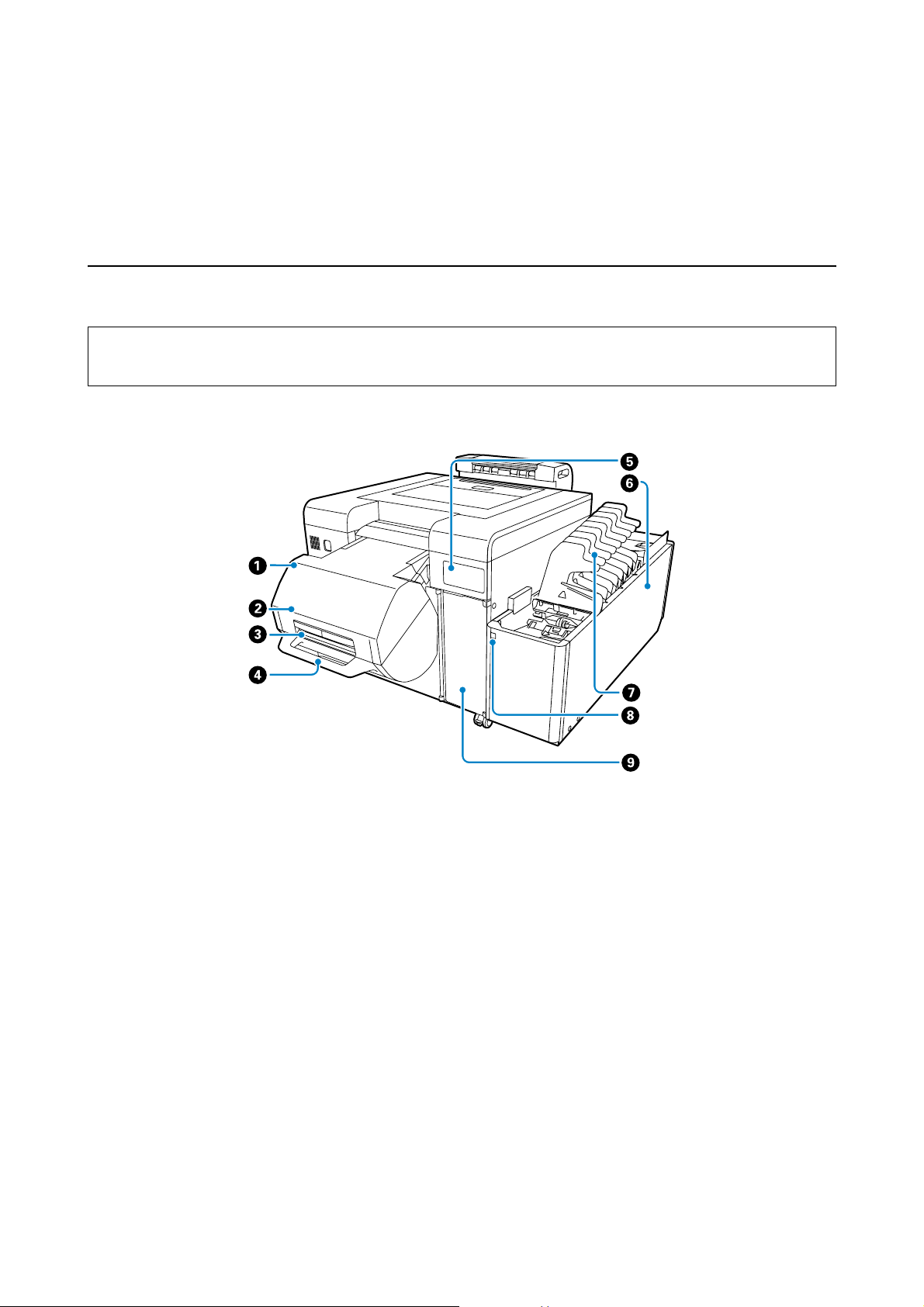
Front
Tip:
Only the Dual Roll Model supports front roll paper. For the Single Roll Model, see the information for rear roll paper.
When the front roll paper feeder is lowered
A Front roll paper feeder (only for the Dual Roll Model)
Holds the Spindle unit.
U “Replacing Paper” on page 32
B Front roll cover (only for the Dual Roll Model)
Open when loading and removing paper.
U “Replacing Paper” on page 32
C Front roll lever (only for the Dual Roll Model)
Hold when opening the front roll cover.
D Front roll handle (only for the Dual Roll Model)
Hold when raising the front roll paper feeder. Do not move the printer by using the Front roll handle.
6
Page 7

Introduction
E Operation panel
Switches for setting the paper type as well as lights that indicate the status of the printer.
U “Operation panel” on page 16
F Sorter unit (optional)
Automatically sorts prints when the optional sorter unit is installed.
G Sorter tray (Included with the optional sorter unit)
Holds one print order in one tray (or up to 50 sheets in one tray).
H Sorter Drive Switch (Included with the optional sorter unit)
Press when manually feeding to the next optional sorter tray. Press once to move the sorter tray forward by one step.
Always use the switch to move the sorter tray. Do not move it manually.
I Ink Cartridge Cover
Open when replacing the ink cartridge.
U “Replacing Ink Cartridges” on page 63
7
Page 8
Introduction
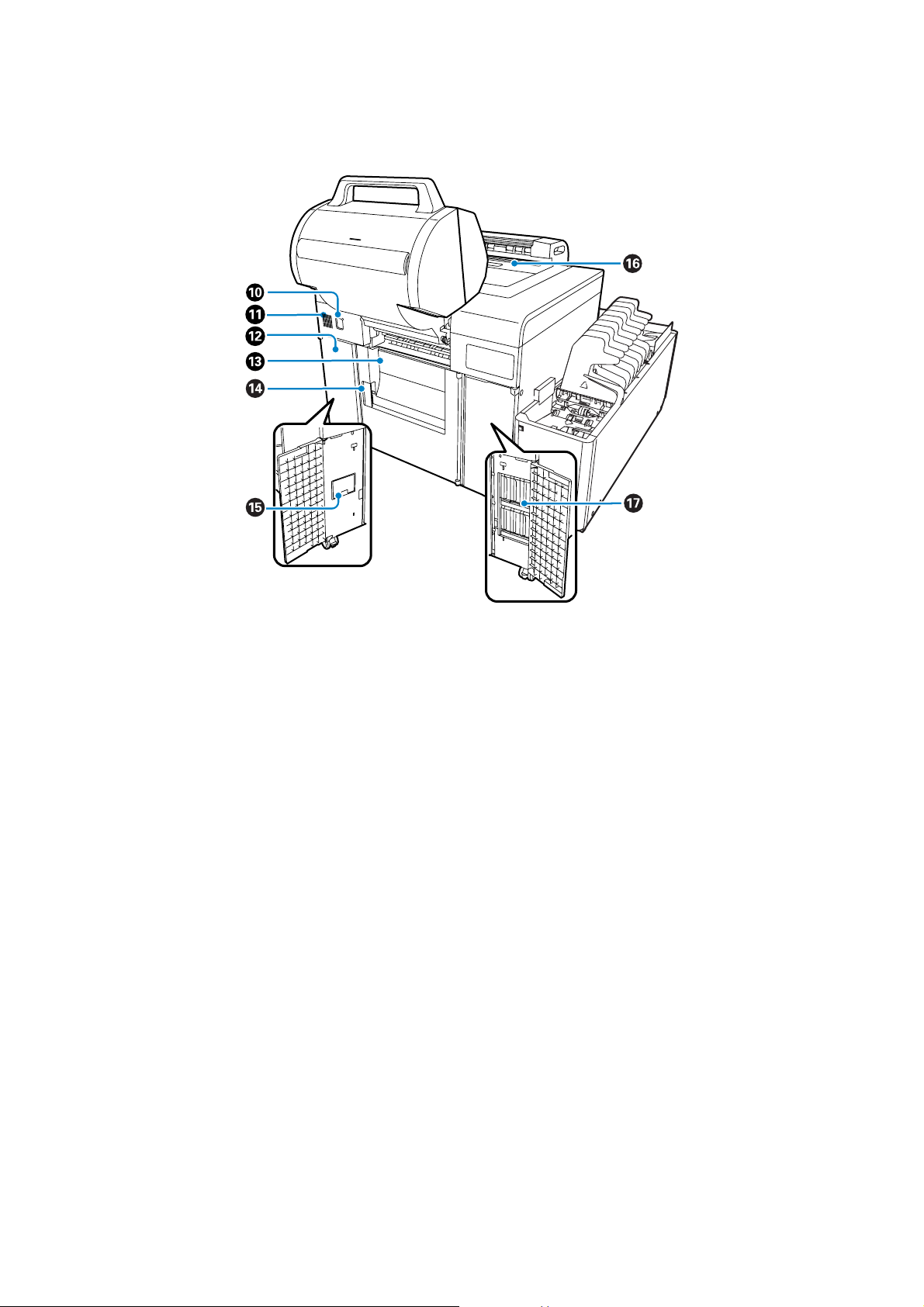
When the front roll paper feeder is raised
J Lock Release button (only for the Dual Roll Model)
Press the Lock Release button while holding down the handle on the front roll paper feeder slightly to release the lock. You
can then raise the front roll paper feeder.
K Air Intake
Takes air into the printer. Do not allow anything to block this intake vent.
L Maintenance Tank Cover
Open when replacing the maintenance tank.
M Rear roll cover
Open when loading and removing paper.
N Rear roll lever
Pull forward to open the rear roll cover.
O Maintenance Tank
Tank for collecting waste ink.
U “Replacing the Maintenance Tank” on page 68
8
Page 9
Introduction
P Top cover/Top tray
Open to clear paper jams and perform maintenance. When the sorter is installed, prints longer than 12 inches (305 mm) are
ejected here.
Q Ink Cartridge
Install the six different color ink cartridges here.
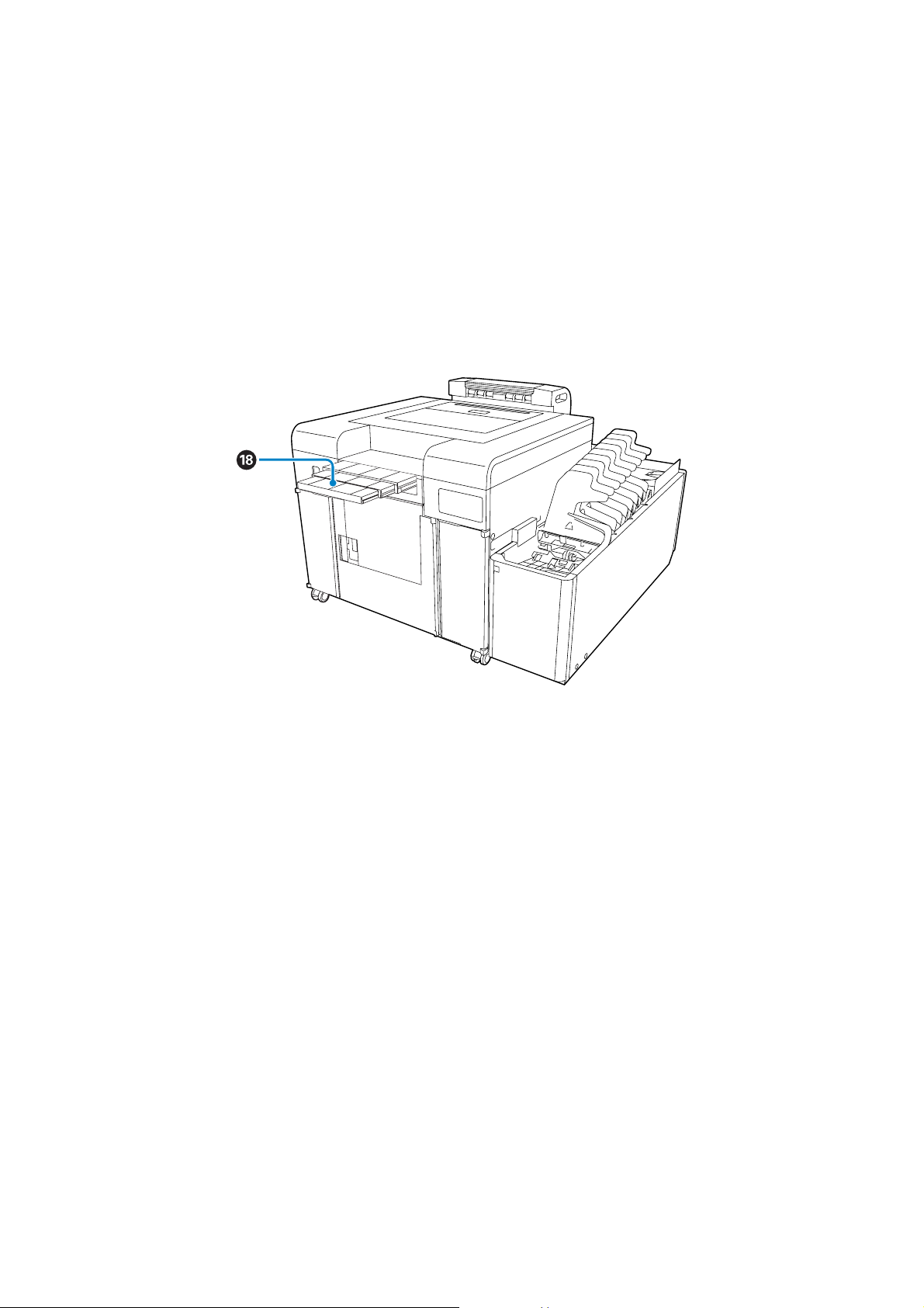
Single Roll Model
R Long print stacker
Supports ejected long paper. Extend this stacker when printing on long paper.
9
Page 10
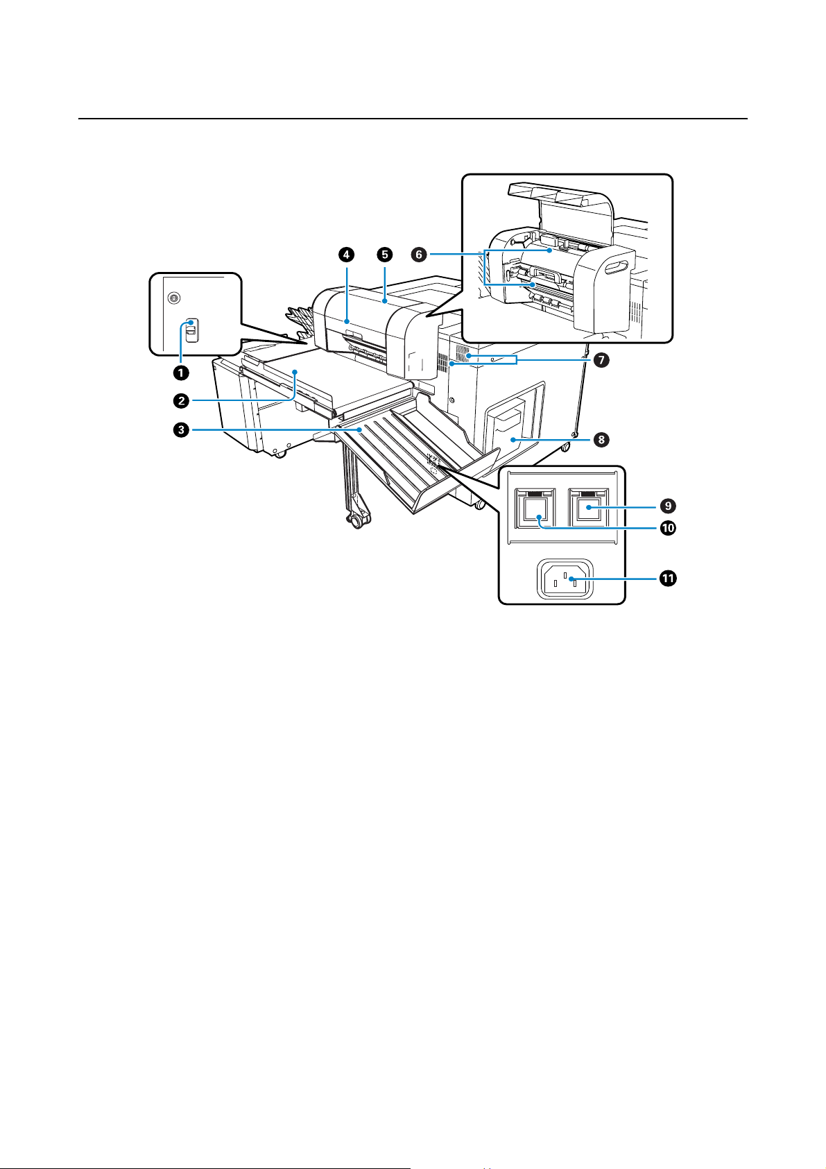
Rear
Introduction
A USB port
Connects the USB cable.
B Conveyor (Included with the optional sorter unit)
Conveys ejected prints to the Side tray or to the sorter.
C Side tray
Ejects print sizes not supported by the Top tray and the sorter, as well as ejecting unnecessary paper that remains in the
printer when an error occurs.
D Long paper ejection unit (Included with the optional sorter unit)
Depending on the print size, paper is ejected to the Top tray, Side tray, or the sorter.
U “Ejected Paper Path and Supported Paper Sizes” on page 61
E Long paper ejection unit cover
Open if there is a paper jam.
10
Page 11

Introduction
F Inside cover for long paper ejection unit (upper/lower)
Open if there is a paper jam.
Loosen the screw for the upper cover section, and then remove.
G Exhaust vent
Vents internal heat from the printer. Do not cover the vent.
H Trimmed waste paper box
Collects trimmed waste paper during printing.
U “Disposing of Trimmed Waste Paper” on page 72
I Humidity control unit power switch
The humidity control unit operates when you press the switch to turn on the light.
U “Adjusting the Humidity in the Roll Paper Feeder” on page 80
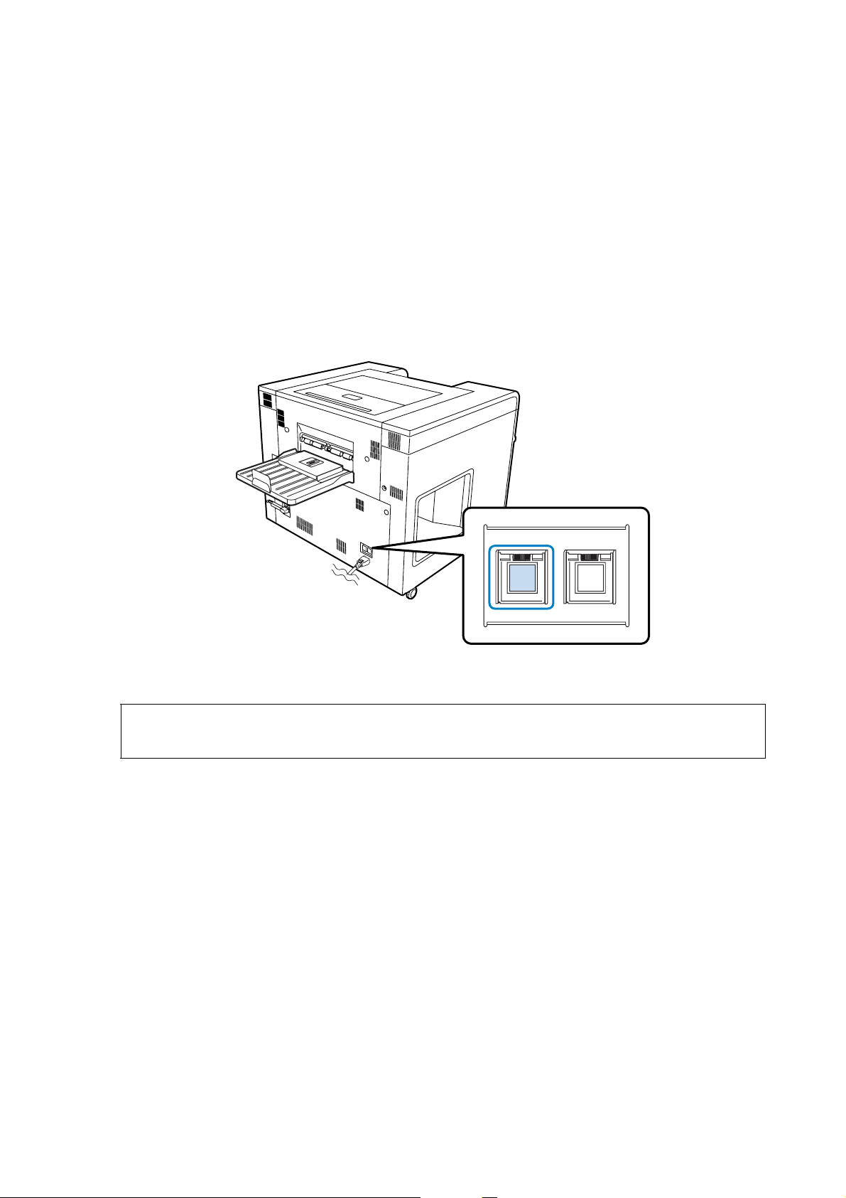
J Power switch
Under normal use, the switch is turned on (the light is on). During an emergency, or when the printer is not used for a long
time, press to switch the power off (the light turns off). Normally, you should turn the printer on or off from the Client PC.
K AC inlet
Connects the power cable.
11
Page 12

Introduction
When the sorter unit is not installed
A Tray
Holds up to 50 prints.
B Sorter port
Connects the sorter unit cable.
12
Page 13
Introduction
Internal
Tip:
Only the Dual Roll Model supports front roll paper. For the Single Roll Model, see the information for rear roll paper.
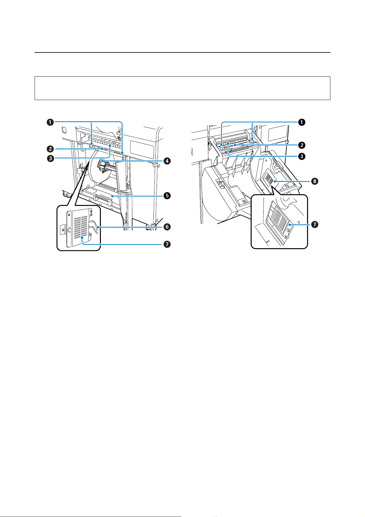
When the rear roll cover is open When the front roll cover is open
A Paper width guide
Adjust to the width of the paper.
B Paper feed slot
Load paper by inserting the leading edge of the paper.
C Paper size guide
This guide helps when adjusting the Paper width guide position.
D Spindle unit
Load roll paper.
E Rear roll paper feeder
Pull forward when removing the Spindle unit.
F Electrodes
The black connector is negative (-), and the red connector is positive (+).
13
Page 14
Introduction
G Humidity control unit
Adjusts the humidity in the roll paper feeder. Turn over to switch between dehumidification and humidification. When the
white side is facing out in the roll paper feeder, dehumidification is performed. When the black side is facing out,
humidification is performed.
U “Adjusting the Humidity in the Roll Paper Feeder” on page 80
H Humidity control unit cover
Open when installing the humidity control unit in the front roll paper feeder, or when switching between dehumidification
and humidification.
U “Changing Between Dehumidification and Humidification” on page 81
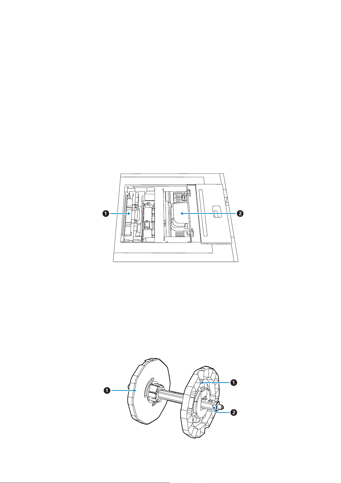
Heater unit/Print Head Unit
A Heater unit
Dries the paper after printing. If a paper jam occurs, remove to check inside the printer.
B Print Head Unit
Fires ink while moving left and right to print. Do not move the Print Head Unit by hand.
Spindle unit
14
Page 15
Introduction
A Flange
Fixes to the left and right of the paper core. After passing through the Spool, rotate the center section to fix the Spool in
place.
B Spool
After fixing the paper in place with the Flange, pass it through the Flange.
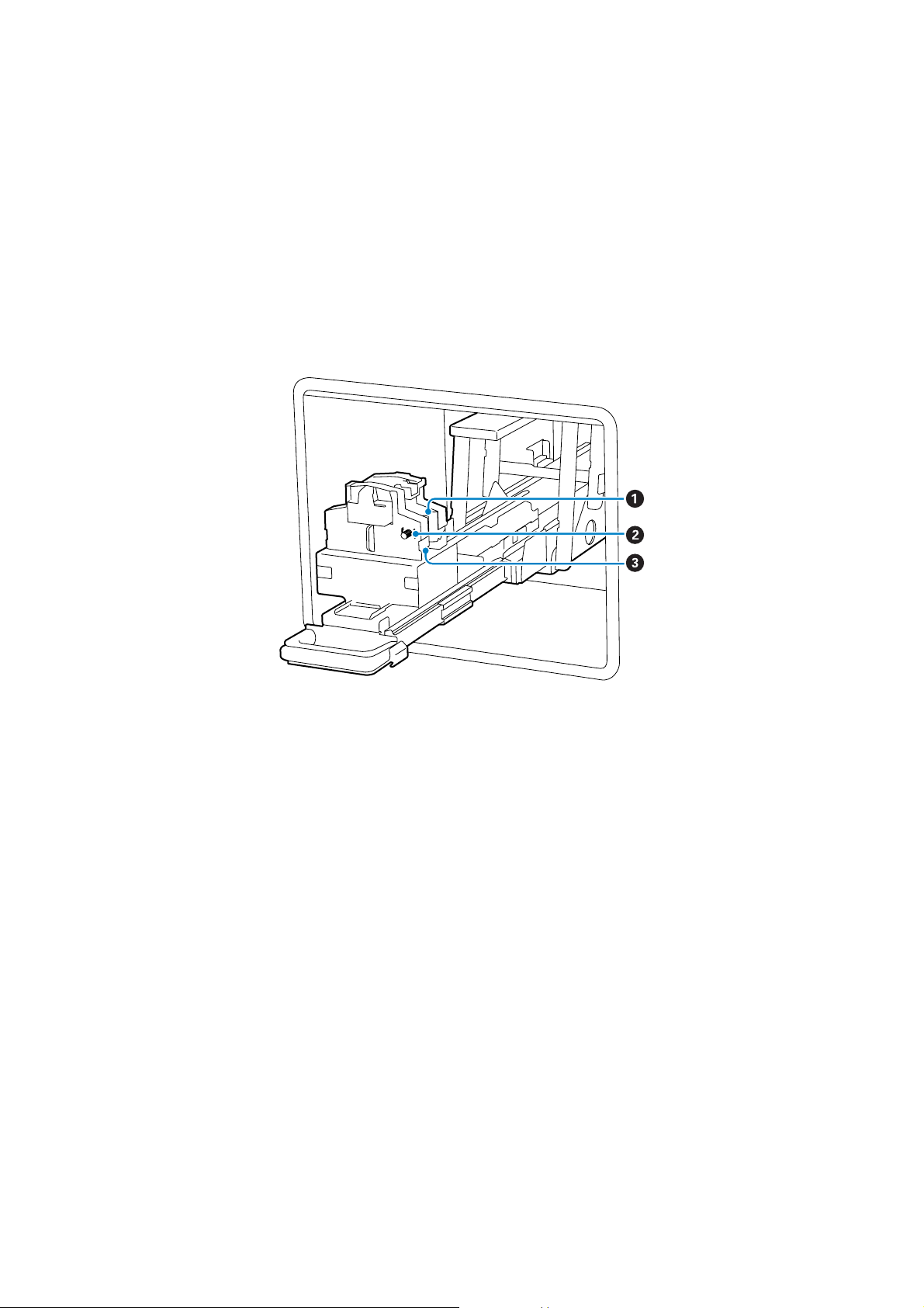
Back printing unit
A Ribbon cassette
A Ribbon cassette for printing on the back of prints. Two ribbon cassettes allow you to print two lines on the back of your
prints. If the printing quality starts to look too light, replace the Ribbon cassette.
U “Replacing Ribbon Cassettes” on page 75
B Knob
Turn the knob to take up the ribbon slack. After taking up the slack, load the ribbon in the Ribbon cassette.
C Handle
Align with the groove in the Ribbon cassette to fix it in place.
15
Page 16
Operation panel
Introduction
Tip:
Only the Dual Roll Model supports front roll paper. For the Single Roll Model, see the information for rear roll paper.
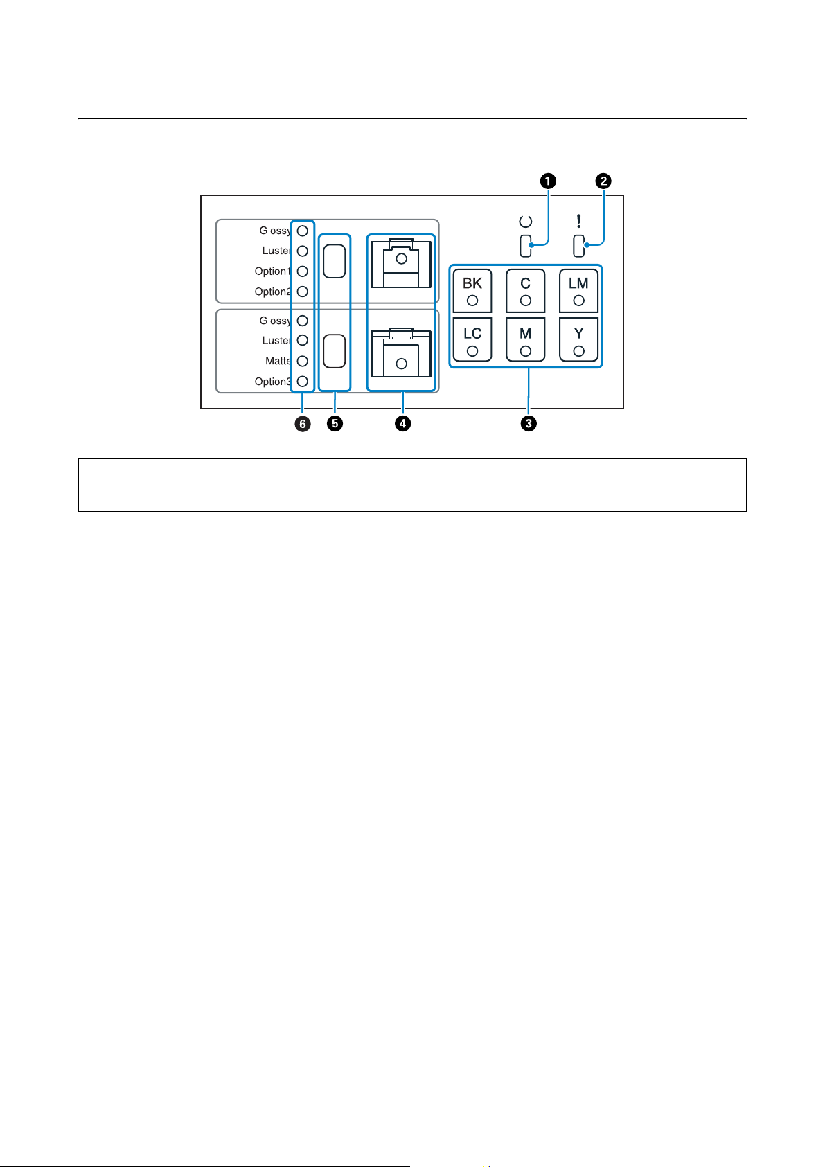
A p light (green)
The printer's operational status is indicated by a lit or flashing light.
On: The printer is ready.
Flashing: Operations such as printing, initializing, or maintenance, are being performed.
Off: The printer is off, or an error has caused operations to stop.
B 0 light (orange)
The printer's error status is indicated by a lit light.
On: An error has occurred, it is recovering from an error, or a service call error has occurred.
Off: The printer is off, or no errors have occurred.
C Ink status light (orange)
Ink cartridge error status is indicated by a lit light.
On: If the ink light is on, printing cannot be performed because ink is running low, or an error has occurred.
Off: The printer is off, or no ink cartridge errors have occurred.
D Paper status light (orange)
Roll paper feeder error status is indicated by a lit or flashing light.
On: If the light is on, there is no paper in the roll paper feeder, or paper is running low.
16
Page 17

Introduction
D Paper status light (orange)
Flashing: If the light is flashing, a paper jam has occurred in the roll paper feeder.
Off: The printer is off, or no paper errors have occurred.
E Paper type setting switch
Press to change the paper type. The paper type changes each time the button is pressed, and the current paper type is
indicated by the lights. Match the paper type to the type of paper loaded.
The switch is enabled when the roll paper feeder cover is open, and paper is removed.
You cannot change to paper for Option 1, 2, or 3.
F Paper type light (green)
The paper type setting is indicated by a lit or flashing light.
On: Indicates the paper type setting.
Flashing: The paper type can be changed.
Off: The power is off, or the paper type cannot be set in the current status.
17
Page 18
Introduction
Notes on Safety
To use this product safely, be sure to read the manual supplied with the product before use. Not handling this
product as described in the manual supplied could cause a breakdown or an accident to occur. Keep this manual
close at hand to solve any unknown issues that may arise with the product.
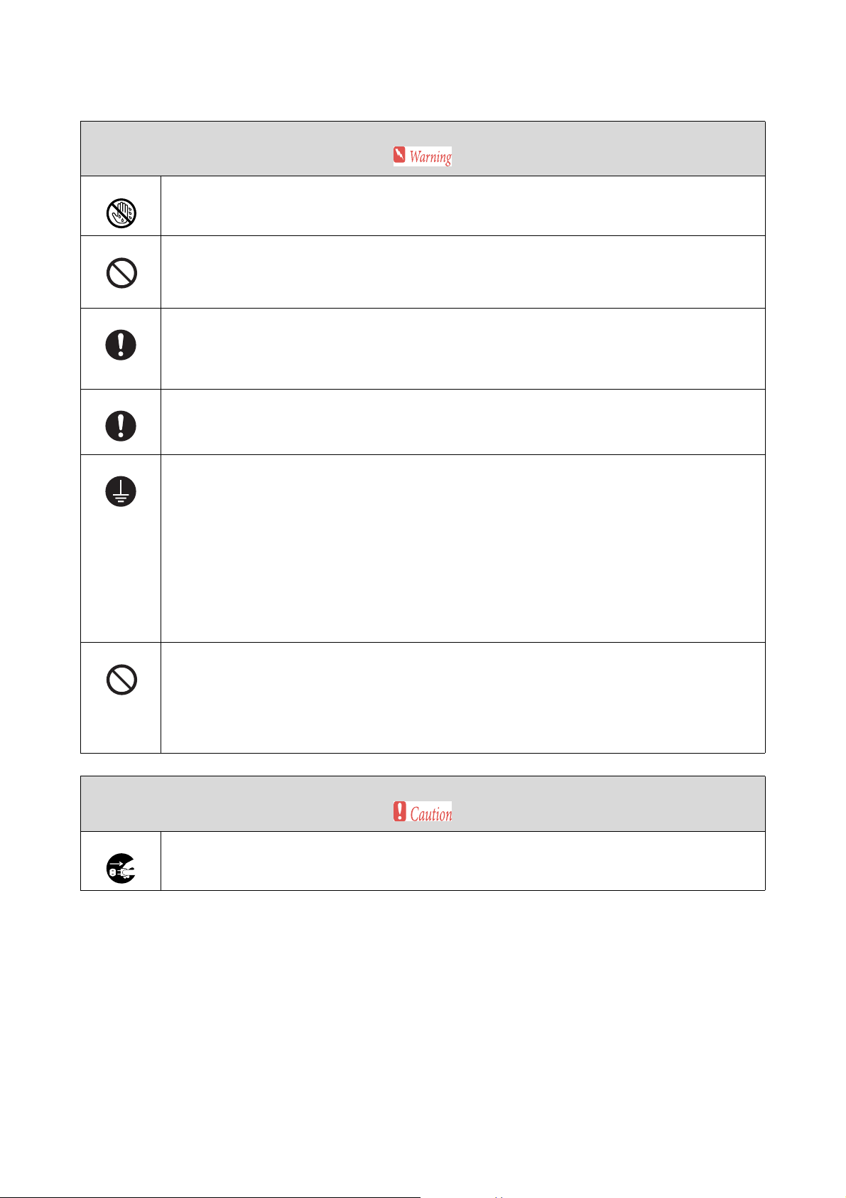
Meaning of Symbols and Marks
Warning:
w
This symbol indicates information that, if ignored, could possibly result in serious injury or even death due to
incorrect handling.
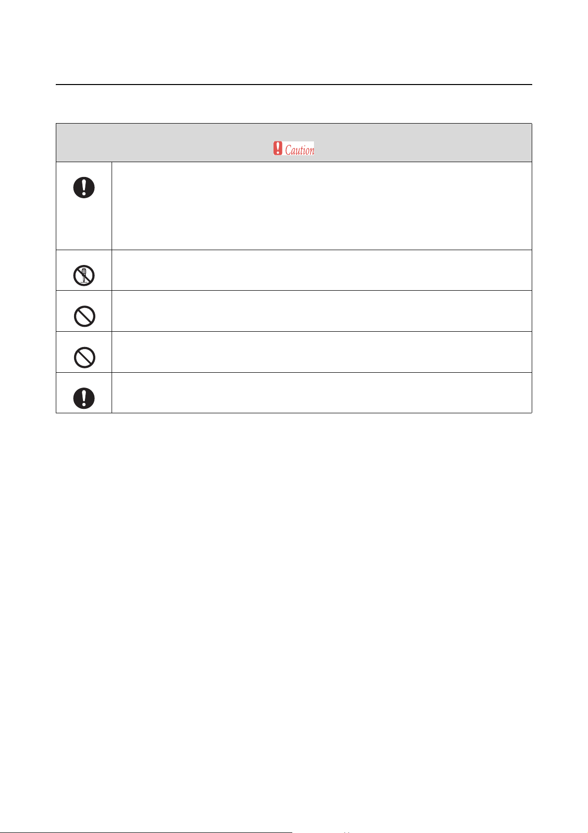
Caution:
c
This symbol indicates information that, if ignored, could possibly result in injury or damage to property due to
incorrect handling.
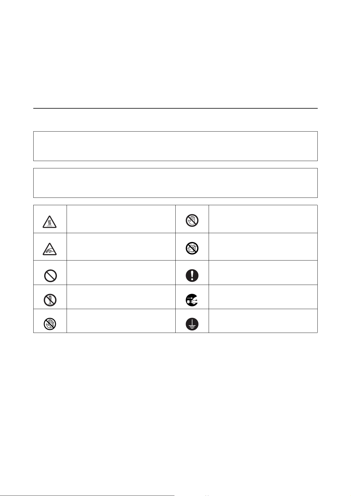
Indicates a high-temperature warning. Indicates that this area should not be
touched.
Indicates that fingers could be trapped or
injured.
Indicates forbidden actions. Indicates items (instructions/operations) that
Indicates that disassembly is forbidden. Indicates that the plug should be
Indicates that you should not touch the
product with wet hands.
Indicates that the product should not get wet.
must be performed.
disconnected from the electrical outlet.
Indicates that grounding should be
performed before use.
18
Page 19
Notes on Installation
Do not block the products airflow vents.
If the airflow vents are blocked, the internal temperature rises and could cause a fire.
Do not set it up in a location in which it could be covered by a cloth and so on, or in an area with poor
ventilation.
Also, be sure to secure the installation space indicated in the manual.
U “External Dimensions and Necessary Space” on page 152
Do not install or store it in an unstable location, or in a location where it is subject to vibrations from other
equipment.
If it falls or slips, it could cause an injury.
Introduction
Do not place it in smoky or dusty locations, humid locations, or locations where it is likely to get wet.
Electric shock or fire could occur.
Because the product is heavy, it should not be carried by one person.
When unpacking or moving the product, make sure it is carried by at least three people.
See the following for more information on the product's mass.
U “Printer Specifications” on page 149
Do not move this printer by using the Front roll handle.
When lifting the product, place your hands in the locations indicated in the manual, and then lift.
If you lift the product with your hands placed in other areas, your fingers could be trapped if you drop the
product or when the product is lowered, which could cause an injury.
If this product is placed in a stand with casters (wheels), make sure the casters are locked in place and cannot
move before performing operations.
If the stand moves unexpectedly during operations, it could cause an injury.
19
Page 20
Notes on Handling
Do not use near volatile substances such as alcohol or thinner, and do not use near fires.
Electric shock or fire could occur.
Do not use the product in an abnormal condition, such as if it is emitting smoke or if you notice any strange
odors or noises.
Electric shock or fire could occur.
If an abnormality does occur, turn off the power immediately, disconnect the plug from the electrical outlet,
and then contact a technical representative.
Do not use this product if foreign bodies, water, or other liquids have entered the product.
Electric shock or fire could occur.
Turn off the power immediately, disconnect the plug from the electrical outlet, and then contact a technical
representative.
Introduction
Only perform operations as instructed in the manual.
Performing repairs is dangerous. Never perform repairs yourself.
Do not use it in locations that may have inflammable or explosive gas and so on in the atmosphere. Also, do not
use sprays containing inflammable gas inside or around this product.
A fire could ignite.
Do not perform any wiring operations other than instructed in the manual.
A fire could ignite. Also, equipment connected to the product could be damaged.
Do not touch any parts of the product, except as instructed in the manual.
Electric shock, burns or injury could occur.
Do not drop any metallic or flammable objects into this product through the openings.
Electric shock or fire could occur.
Do not place any heavy objects on this product.
If it falls or breaks, it could cause an injury.
When moving this product, check that the power is off, the plug is disconnected from the electrical outlet, and
all wiring has been disconnected before moving.
If the cable is damaged, electric shock or fire could occur.
When turning on the product or while printing, do not put your fingers near the paper eject roller section.
If your fingers are caught in the paper eject roller, an injury could occur. Remove paper after it has been
completely ejected from the product.
20
Page 21
Introduction
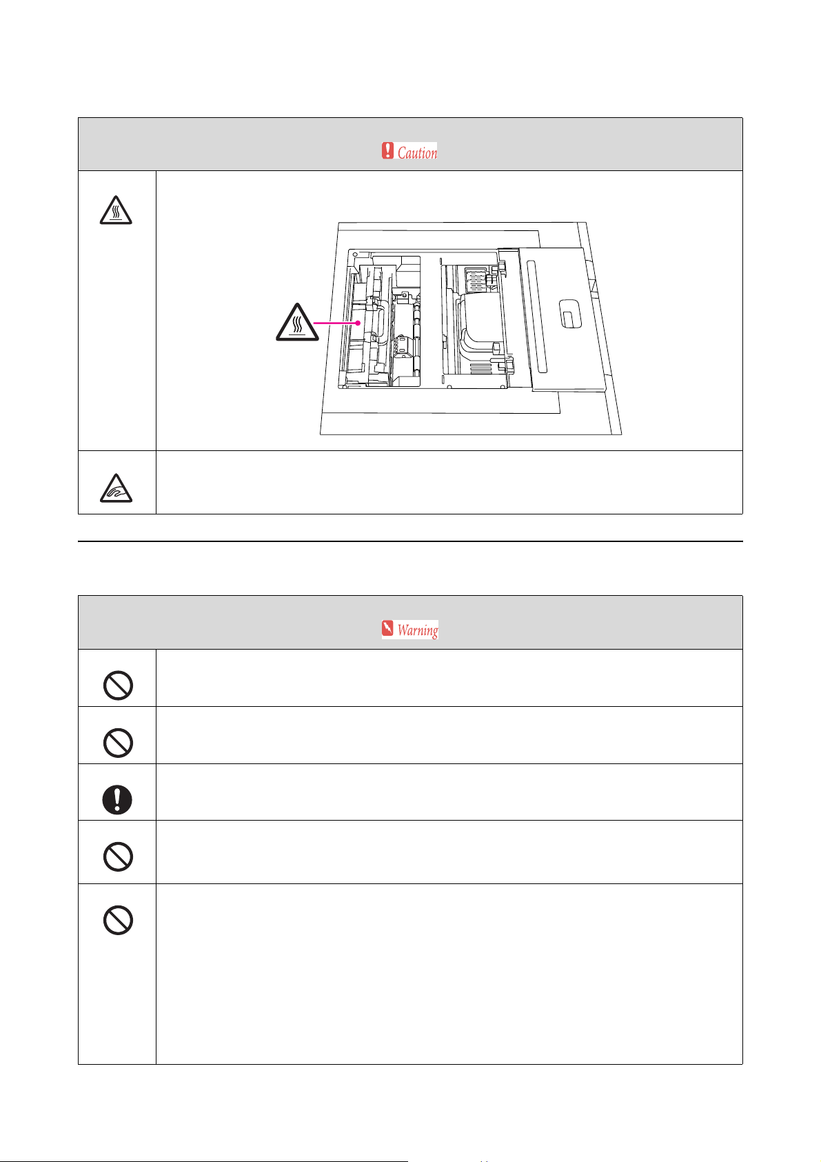
If you need to open the printer's top cover while in use, do not touch the heater or the cover which are indicated
by warning labels. Because internal parts reach high temperatures, burns could occur.
When opening and closing the printer cover, do not place your hands near the section where the cover joins
with the main body of the printer.
If your fingers or hands are too close to this section, an injury could occur.
Notes on the Power Supply
Use only the type of the power supply indicated on the label.
Electric shock or fire could occur.
Do not use the power plug if there are any foreign bodies, such as dust, attached.
Electric shock or fire could occur.
Make sure the power plug is inserted all the way into the electrical outlet before use.
Electric shock or fire could occur.
Only use the product with the power cable supplied. Also, do not use the power cable supplied with any other
equipment.
Electric shock or fire could occur.
Do not use the power cable if it is damaged.
Electric shock or fire could occur.
Contact a technical representative if the power cable is damaged.
Furthermore, observe the following points to prevent the power cable from being damaged.
O Do not modify the power cable
O Do not put any heavy objects on the power cable
O Do not bend too far, twist, or pull the power cable
O Do not place the power cable near a heater
21
Page 22
Introduction
Do not plug in or unplug the power plug with wet hands.
Electric shock could occur.
Do not use the power cable with an "octopus" extension cable.
Heat is generated and could cause a fire.
Connect directly to a domestic electrical outlet.
Periodically disconnect the power plug from the electrical outlet and clean the base of the plug as well as
between the blades.
When the power plug is left connected to the electrical outlet for extended periods of time, dust can collect
between the blades and the base of the plug which could cause a short-circuit and start a fire.
When disconnecting the power plug from the electrical outlet, grip the plug itself and pull it out. Do not pull it
by the cable.
If the cable is damaged or the plug is deformed, electric shock or fire could occur.
Set up a grounded (earthed) connection to prevent short circuits.
If you use the product without the grounding wire (earth wire) installed, electric shock or fire could occur.
Ground the power cable using one of the following methods.
O With the grounding terminal on the electrical outlet
O With a copper chip and so on buried at least 25.6 inches (65 cm) below ground
O With a type D grounding terminal for grounding construction
Before installing or detaching the grounding wire, make sure the power plug is disconnected from the electrical
outlet. Check the grounding for the electrical outlet you are using. Contact your local dealer if you are unable to
ground the product.
Do not connect the grounding wire to the following locations.
O Gas pipes (a fire or explosion could occur)
O Grounding wire for telephones or lightning conductors (this is dangerous as a massive surge of electricity
could be generated if it is struck by lightning)
O Water pipes or faucets (grounding is not performed if there is any plastic in the pipes)
If you do not use the product for a long time, disconnect the plug from the electrical outlet for safety reasons.
22
Page 23
Notes on Consumables
Take the following measures if ink gets on your skin, or in your eyes or mouth.
O If any ink gets on your skin, wash immediately with soap and water.
O If any ink gets in your eyes, flush them immediately with water. Inflammation or light inflammation of the
eyes may occur if they are not treated immediately. If any abnormalities occur, contact a doctor
immediately.
O If any ink gets in your mouth, spit it out immediately and consult your doctor.
Do not disassemble the ink cartridge.
If it is disassembled, ink may get in your eyes or on the skin.
Do not shake the ink cartridge too hard.
If you shake or swing it too hard, ink may leak from the cartridge.
Introduction
Do not rub the edge of printed paper with your hand.
The edges of the paper are thin and sharp and could cause a paper cut.
Do not store ink cartridges within the reach of children.
23
Page 24

Introduction
Notes on Usage
Notes on Printer Usage
O Do not suddenly change the temperature in the room where this product is set up.
If the temperature changes suddenly, drops of water (condensation) could occur inside the product which may
have an adverse effect on operations.
O Do not place any containers containing water, such as vases or cups, on this product. If water enters the product,
it could cause it to malfunction. Also, do not put any heavy objects on the product.
O Vents have been installed on this product. Vents have been installed to take in and exhaust air from this
product. Do not place any objects near the vent, and do not cover the vent with film sheets or paper and so on.
O Do not use accessories supplied with this product with any other devices.
O Do not print solid white or all white data. Otherwise the paper may be jammed and cause a malfunction.
O The safety device operates if the printer cover is opened while printing, and printing stops automatically.
Printing restarts when the error is cleared from the Client PC.
O If the printer is not used for a long time, after performing "Post-Operation Check" as normal, leave the ink
cartridges installed when storing.
O Contact a technical representative if you are planning to move or transport the printer.
O Do not move this printer by using the Front roll handle.
O Regardless of the operating system settings, computers on your system cannot enter sleep mode.
O Depending on the environment being used, image size, and image type, the print may not be delivered to the
correct tray or sorter. If the prints are not delivered to the correct tray or sorter, or not delivered in the correct
order, remove the ejected paper manually and place in the correct position.
Notes on Handling Ink Cartridges
O If you move ink cartridges from a cold place to a warm place, leave them at room temperature for more than
four hours before use.
O We recommend using the ink cartridge before the expiry date printed on the individual packaging boxes. If you
use an ink cartridge beyond the expiry date, it may affect print quality.
O Do not touch the ink supply port on the ink cartridges. Ink may have leaked from the ink cartridge.
O Because the green IC chip contains the cartridge's own information such as the remaining ink level, you can still
reinstall and use the ink cartridge after removing it from the printer.
O When you remove the ink cartridge before it is expended, store it without getting dirt on the ink supply port.
The ink supply port has a valve in it so it does not need to be capped.
O Do not touch the green IC chip on the ink cartridges. Doing so may prevent normal operation and printing.
24
Page 25

Introduction
O Do not dismantle or remodel ink cartridges. You may not be able to print properly.
O Do not drop or knock it against hard objects; otherwise, the ink may leak.
O Although nothing may be printed, this printer uses ink from all cartridges during head cleaning and other
maintenance operations to keep the Print Head Unit in good condition.
O Although the ink cartridges may contain recycled materials, this does not effect printer function or
performance.
O Do not leave the printer without ink cartridges installed. The ink in the product may dry up, and you may not
be able to print properly.
O Install an ink cartridge in each cartridge holder. You cannot print unless the correct cartridge is installed in each
cartridge holder.
O Replace ink cartridges when the power is on. If cartridges are replaced when the power is off, the product cannot
detect the amount of ink remaining and so cannot print normally.
O To maintain the quality of the head, this printer stops printing before ink cartridges are completely expended.
O Store ink cartridges in the same environment as the printer's installation environment. Also, avoid direct
sunlight.
Disposing of the Main Printer Unit and Consumables
Entrust waste processing to an industrial waste disposal contractor, and dispose of it in accordance with the law and
local regulations.
25
Page 26
Starting up and Shutting down the Printer
Starting up and Shutting down the Printer
Starting up the Printer
Click Pre-operation Check on the Client PC to start the printer.
In Pre-operation Check, the printer starts after the items that need to be checked manually have been displayed.
When Printer PC is connected to the printer, Printer PC starts automatically.
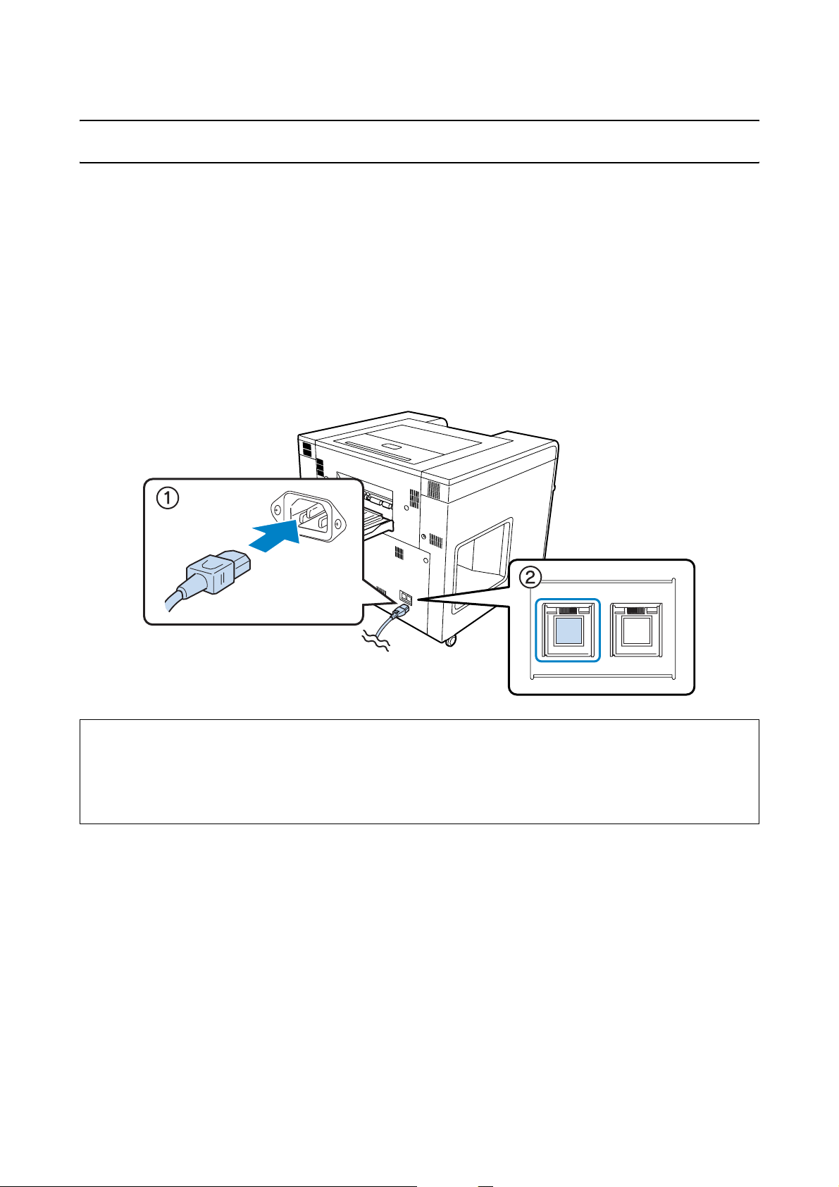
The Power switch on the back of the printer should normally be On (the light is on). If the Power switch is turned
off, check that the power cable is inserted in the AC inlet, and then turn on the Power switch (the light turns on).
Tip:
Normally, you do not need to operate the humidity control unit power switch.
See the following for more information on using the humidity control unit.
U “Adjusting the Humidity in the Roll Paper Feeder” on page 80
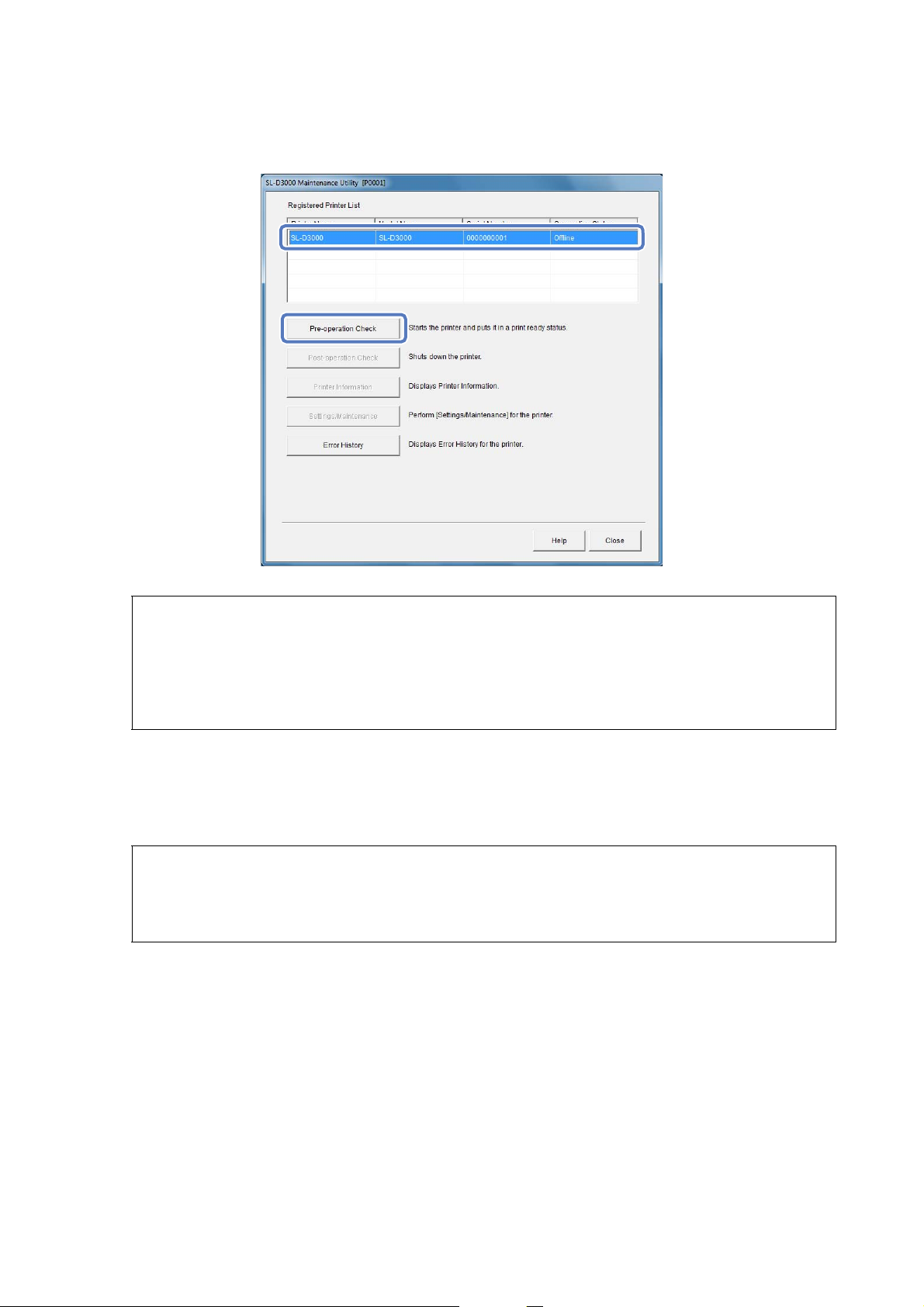
Start the SL-D3000 Maintenance Utility.
A
You can use one of the following methods to display the pre-operation check screen.
On the Client PC, click Start - All Programs - EPSON SL-D3000 System Application - Maintenance
Utility.
26
Page 27
Starting up and Shutting down the Printer
Select the printer you want to start from the Registered Printer List, and then click Pre-operation Check.
B
Tip:
O If the selected printer is already available, the Pre-operation Check button is unavailable.
O If the cable connected to the printer is disconnected, or the printer's Power switch is off, an error message is
displayed because connection is not possible. Check the contents of the message.
U “Errors and Solutions” on page 118
Perform the manual check items displayed on the screen. Click OK after completing the operations.
C
When you click OK, the printer automatically performs a Pre-operation Check. It takes about 4 to 5 minutes
to complete the Pre-operation Check.
Tip:
If the Printer PC does not shut down correctly for any reason such as a power failure, the Printer PC may not start
after performing a Pre-operation Check. If this happens, start the Printer PC manually, and then perform a
Pre-operation Check.
27
Page 28
Starting up and Shutting down the Printer
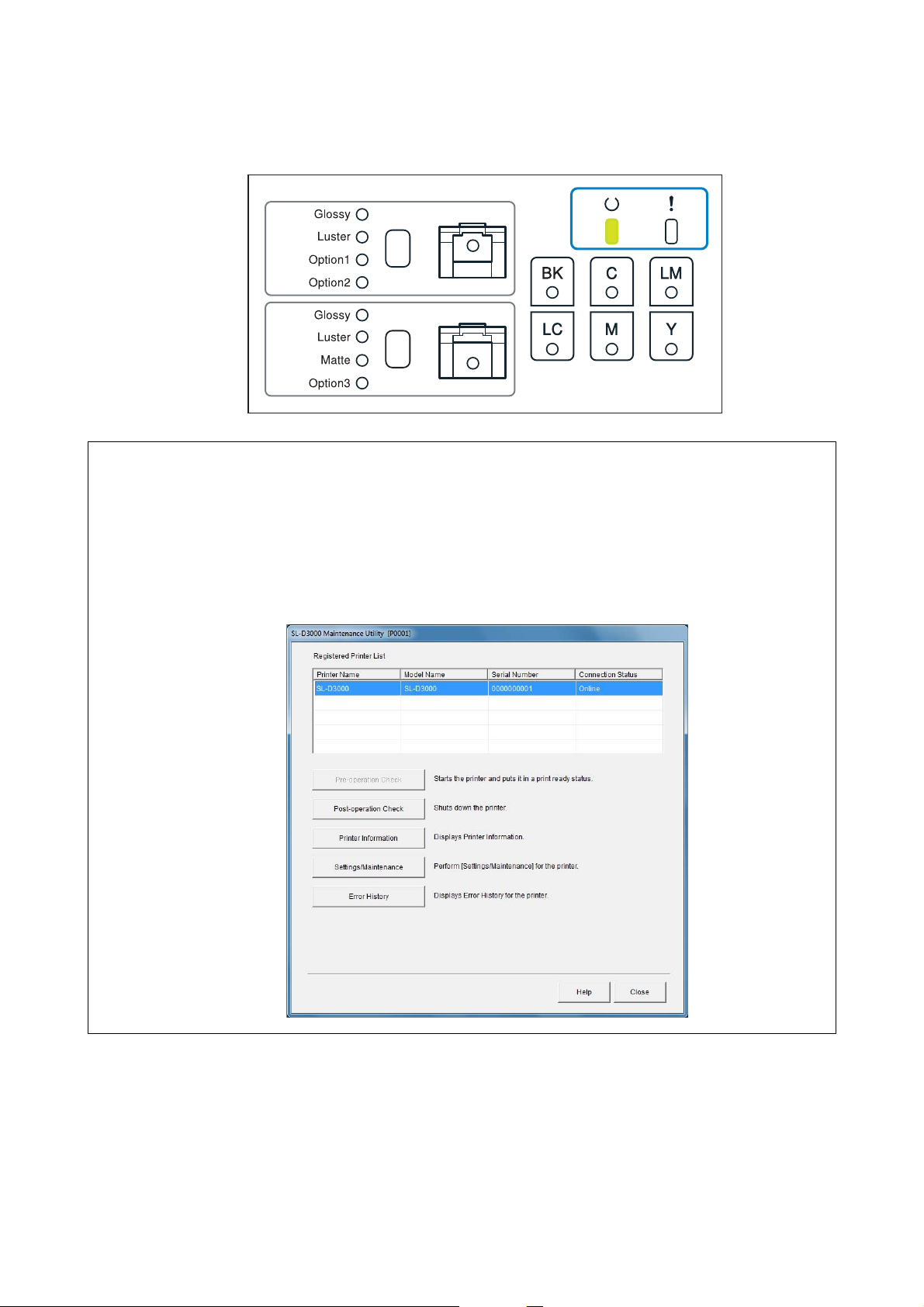
Check that the p light on the Operation panel has changed from flashing to lit.
D
Tip:
O Because you can use the screen to perform printer maintenance and a Post-operation Check, keep the screen open
until you shut down the printer.
O Click Close on the SL-D3000 Maintenance Utility screen to close the screen.
O By clicking Printer Information, you can check information such as the remaining amounts for consumables. Check
as necessary.
U “Printer Information” on page 87
This completes this section.
28
Page 29
Starting up and Shutting down the Printer
Shutting down the Printer
Click Post-operation Check on the Client PC to shut down the printer.
When the printer is shut down in Post-operation Check, and Printer PC is connected to the printer, Printer PC
closes automatically.
The Power switch on the back of the printer should normally be On (the light is on). Normally, you do not need to
turn off the Power switch or disconnect the power cable when you finish work. During an emergency, or when not
using the printer for a long time, turn off the Power switch (the light turns off).
Close the Printer Information and Settings/Maintenance screens if they are open.
A
Tip:
You cannot start the Post-operation Check if the Printer Information and Settings/Maintenance screens are open.
29
Page 30
Starting up and Shutting down the Printer
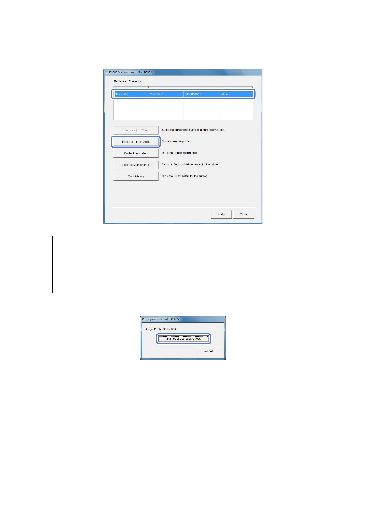
Select the printer you want to close from the Registered Printer List, and then click Post-operation Check.
B
Tip:
In the following situations, the Post-operation Check button is unavailable.
O When the printer has already shut down
O When the cable connected to the printer is disconnected
O When the printer's Power switch is off
Click Start Post-operation Check.
C
Follow the on-screen instructions to check the printer, and then click OK.
D
Once the Post-operation Check is finished, automatic shut-down operations take about 1 to 2 minutes to
complete.
30
Page 31

Click Close to finish.
E
Starting up and Shutting down the Printer
Tip:
If you are using another printer, continue making operations without closing the screen.
This completes this section.
Turning the Power Off in an Emergency
See the following if you need to turn off the power in an emergency.
U “Emergency Stop” on page 145
31
Page 32

Replacing Paper
Replacing Paper
This section explains how to use genuine Epson paper, and how to remove paper from the roll paper feeder and load
new paper.
Tip:
O When paper is out, use the paper status lights on the Operation panel to check which roll paper feeder is empty.
O If the edges of the paper are torn, use scissors to cut the paper so that it is straight, and then load the paper.
O You need to make the following preparations if you want to replace the paper with paper of the same width and type.
O Before replacing, make a note of the amount remaining for the current paper
O When replacing the paper, set the amount of paper remaining after replacement from the Client PC
If the remaining amount of paper is not set correctly, the paper level is not displayed correctly.
U “Paper Settings” on page 90
O Rear roll paper feeder operations differ from front roll paper feeder operations. See the following for more
information.
U “Replacing Paper in the Rear Roll Paper Feeder” on page 36
U “Replacing Paper in the Front Roll Paper Feeder” on page 49
O Only the Dual Roll Model supports front roll paper. For the Single Roll Model, see the information for rear roll paper.
Genuine Epson Paper
For optimum print quality, we recommend using the following genuine Epson paper.
Professional Photo Paper Glossy
Professional Photo Paper Luster
For more details about genuine Epson paper, see the following sections.
U “Consumables and Optional Products” on page 147
32
Page 33

Replacing Paper
Printer Driver Settings
Set "Paper Type" for the printer driver according to the paper name as shown in the following table.
Paper Name Printer Driver Paper Type Setting
Professional Photo Paper Glossy* Professional Paper for SureLab <Glossy>
Professional Photo Paper Luster* Professional Paper for SureLab <Luster>
* Set High Quality in the printer driver's image settings to achieve high quality printing when using Professional Photo Paper
Glossy and Professional Paper Photo Luster.
Tip:
We recommend updating your printer driver to the latest version. Check the Epson home page for more information on
the printer driver download service. (http://www.epson.com/support)
Notes on Handling Paper
O The printable surface is the outer surface of the roll paper ( ).
O Be careful not to fold the paper or to scuff the printable surface.
O Do not touch the printable surface of the paper. Moisture and oil from your hands can stain the paper and effect
print quality.
O Handle the paper by the edges, or wear cotton gloves.
O Make sure the paper does not get wet.
O Do not use paper that is wrinkled, fuzzy, torn, or dirty.
33
Page 34

Replacing Paper
Notes on Paper Storage
O When storing paper before and after opening, store in the following environment and keep it out of direct
sunlight.
O We recommend storing paper in its original packaging, and then placing it in a separate packing box.
O To prevent the paper from unravelling, we recommend using the paper belt supplied to keep the paper in place.
O After opening, remove any unused paper from the core unit, wind it up, and then store. If the paper is left
installed in the printer for extended periods of time, the paper quality may decline.
Paper Type Storage Environment
Temperature Humidity
Professional Photo Paper Glossy 59 to 77 °F (15 to 25 °C) 20 to 80 %
Professional Photo Paper Luster 59 to 77 °F (15 to 25 °C) 20 to 80 %
Notes when Printing
O Make sure that the leading edge of the paper is cut horizontally in a straight line, perpendicular to the long side
of the paper.
O Use the paper at the room temperatures shown below. If the paper is not used in the following environment, the
print quality may decline.
Paper Type Temperature Humidity
Professional Photo Paper Glossy 59 to 86 °F (15 to 30 °C) 30 to 60 %
Professional Photo Paper Luster 59 to 86 °F (15 to 30 °C) 30 to 60 %
34
Page 35

Replacing Paper
Storing and Displaying Printed Paper
O Make sure the printed surface does not get scuffed or scratched.
O To maintain color tones, avoid high temperatures, high humidity, direct sunlight, and make sure you store the
prints in a dark environment.
O Try to avoid displaying prints outdoors and in direct sunlight. Otherwise the colors may fade faster than
expected.
O When exhibiting prints indoors, we recommend keeping them in frames such as glass. This will help to
maintain the print quality without fading for a long time.
35
Page 36

Replacing Paper
Paper Feed Section
The configuration for the paper feed section of the printer changes depending on the model. Although all models
are equipped with a rear roll paper feeder, only the Dual Roll Model is equipped with a front roll paper feeder. Also,
the type of paper supported and the capacity differs for each type of feeder as shown in the following table.
Paper Feed Section Supported Paper Types Available Paper Width
Front roll paper feeder Professional Photo Paper Glossy
Professional Photo Paper Luster
Rear roll paper feeder Professional Photo Paper Glossy
Professional Photo Paper Luster
4 to 8 inches
(102 to 203 mm)
4 to 12 inches
(102 to 305 mm)
Notes when Loading Paper
O When using the paper for the first time after purchase, we recommend cutting off approximately 3 ft (1 meter)
before use. Depending on the paper's transportation environment, the print quality may decline for this first
part of the paper.
Replacing Paper in the Rear Roll Paper Feeder
Removing Paper
Prepare the following items.
A
Items Explanation
New paper for loading You can load the following genuine Epson paper in the rear roll paper feeder.
Professional Photo Paper Glossy
Professional Photo Paper Luster
A linen or vinyl cloth To avoid soiling the paper, place the Spindle unit on the cloth when loading/removing
the paper.
Gloves Wear gloves to avoid soiling the paper when handling it.
36
Page 37

Replacing Paper
Check that the p light on the Operation panel is lit.
B
If the p light is flashing, the printer is operating. Wait until operation has stopped.
For the Dual Roll Model, hold down the handle of the front roll paper feeder a little ( ) while pressing the
C
Lock Release button( ), and then raise the front roll paper feeder.
When the roll paper feeder is raised, a warning buzzer sounds.
Open the rear roll cover.
D
37
Page 38

Replacing Paper
Slide the right Paper width guide to the right.
E
Remove the paper from the Paper feed slot, and rewind the paper.
F
Grip the handle and pull out the rear roll paper feeder.
G
38
Page 39

Remove the Spindle unit.
H
Replacing Paper
Removing Flanges
Release the locks on the left and right flanges.
A
Rotate the center sections of the Flange counterclockwise to release the lock.
Remove the Spool.
B
39
Page 40

Replacing Paper
Stand the Spindle unit vertically on a flat surface, and then remove the top Flange.
C
Tip:
It does not matter which Flange is at the top.
Remove the paper.
D
Tip:
After removing the paper, rewind it correctly and then store it in the original packaging that came with the paper.
Installing Flanges
Remove the new paper from its packaging, and stand it vertically on the flat surface. Next, wipe away paper
A
particles from the top of the paper with a damp cloth.
40
Page 41

Replacing Paper
Set the Flange on the paper surface from which paper particles have been wiped away.
B
Place the paper straight to the Flange.
Tip:
Either Flange can be set.
Position the paper so that the surface to which the Flange has not been set is face up.
C
Next, wipe away paper particies with a damp cloth.
Place the other Flange on the other end of the paper.
D
Align the triangular marks on the flanges as shown in the illustration below.
Place the Spindle unit on its side so that the paper is in the position shown below.
E
41
Page 42

Replacing Paper
Make sure the triangular marks on the flanges have not shifted out of position.
Insert the Spool so that the gear section ( ) is on the left.
F
Note:
Note the direction of the Spool and the direction of the paper. If the directions are not correct, the paper cannot be
loaded correctly.
Adjust the position of the Spool so that it is at the center of the Spindle unit.
G
Match the edges of the flanges to the scale "|" marks on the paper size display according to the width of the
paper.
Lock the flanges on both sides.
H
42
Page 43

Replacing Paper
Rotate the center sections of the flanges clockwise to lock them in place.
Loading Paper
Place the Spindle unit into the rear roll paper feeder in the direction shown in the illustration below, and then
A
push the rear roll paper feeder into the printer.
Tip:
Remove any tape or protective sheets from the paper.
43
Page 44

Replacing Paper
Slide the rear roll paper feeder into the printer.
B
Adjust the position of the paper width guides to the width of the paper.
C
When adjusting the position of the paper width guides, raise the guides slightly, and then move to the left and
right.
Adjust the triangle mark on the paper width guides to the scale. The scale is displayed in millimeters (with
inches in parentheses).
Slide the right Paper width guide to the right.
D
44
Page 45

Replacing Paper
Without lifting forwards, slide the Paper width guide to the right within the movable area.
Match the left edge of the paper with the left Paper width guide, and pass the leading edge of the paper
E
through the groove in the paper width guides.
45
Page 46

Replacing Paper
Insert until the leading edge of the paper is visible beyond the roller as shown in the illustration below.
F
Rotate the flanges forward slowly to take up the slack in the paper.
G
Note:
Printing when the paper is sagging could decrease print quality and cause a paper jam. Make sure you take up the
slack in the paper.
46
Page 47

Replacing Paper
Slide the right Paper width guide to the left until it is flush with the edge of the paper.
H
Note:
O Make sure that there is no gap between the Paper width guide and the edge of the paper. If there is a gap, the
print position may be misaligned, or a feeding error may occur.
O Do not push the Paper width guide against the paper too forcefully. The paper may be damaged, or it may
cause a paper jam.
If the paper type has changed, set the paper type on the Operation panel.
I
Each time you press the Paper type setting switch on the rear roll paper feeder, the paper type changes and
the light flashes to indicate the current paper type.
Tip:
If you clear the cover open error by clicking OK on the Client PC, you cannot change the paper type. To change the
paper type, remove the paper from the Paper feed slot, reinsert it, and then try again.
47
Page 48

Replacing Paper
Close the rear roll cover.
J
For the Dual Roll Model, press the front roll paper feeder down as far as it will go.
K
Check that the front roll paper feeder is fixed in place.
Tip:
If an error is displayed on the Client PC, you need to clear the error.
Click OK on the error message.
Next, check that the p light on the Operation panel is lit.
This completes this section.
48
Page 49

Replacing Paper
Replacing Paper in the Front Roll Paper Feeder
Only the Dual Roll Model supports front roll paper.
Removing Paper
Prepare the following items.
A
Items Explanation
New paper for loading You can load the following genuine Epson paper in the rear roll paper feeder.
Professional Photo Paper Glossy
Professional Photo Paper Luster
A linen or vinyl cloth To avoid soiling the paper, place the Spindle unit on the cloth when loading/removing
the paper.
Gloves Wear gloves to avoid soiling the paper when handling it.
Check that the p light on the Operation panel is lit.
B
If the p light is flashing, the printer is operating. Wait until operation has stopped.
Pull the Front roll lever forward and release the lock, and then open the front roll cover.
C
When the cover is opened, a warning buzzer sounds.
49
Page 50

Replacing Paper
Remove the paper from the Paper feed slot, and rewind the paper.
D
Remove the Spindle unit.
E
Removing Flanges
Release the locks on the left and right flanges.
A
Rotate the center sections of the Flange counterclockwise to release the lock.
50
Page 51

Replacing Paper
Remove the Spool.
B
Stand the Spindle unit vertically on a flat surface, and then remove the top Flange.
C
Tip:
It does not matter which Flange is at the top.
Remove the paper.
D
Tip:
After removing the paper, rewind it correctly and then store it in the original packaging that came with the paper.
51
Page 52

Replacing Paper
Installing Flanges
Remove the new paper from its packaging, and stand it vertically on the flat surface. Next, wipe away paper
A
particles from the top of the paper with a damp cloth.
Set the Flange on the paper surface from which paper particles have been wiped away.
B
Place the paper straight to the Flange.
Tip:
Either Flange can be set.
Position the paper so that the surface to which the Flange has not been set is face up.
C
Next, wipe away paper particies with a damp cloth.
52
Page 53

Replacing Paper
Place the other Flange on the other end of the paper.
D
Align the triangular marks on the flanges as shown in the illustration below.
Place the Spindle unit on its side so that the paper is in the position shown below.
E
Make sure the triangular marks on the flanges have not shifted out of position.
Insert the Spool so that the gear section ( ) is on the left.
F
Note:
Note the direction of the Spool and the direction of the paper. If the directions are not correct, the paper cannot be
loaded correctly.
53
Page 54

Replacing Paper
Adjust the position of the Spool so that it is at the center of the Spindle unit.
G
Match the edges of the flanges to the scale "|" marks on the paper size display according to the width of the
paper.
Lock the flanges on both sides.
H
Rotate the center sections of the flanges clockwise to lock them in place.
54
Page 55

Replacing Paper
Loading Paper
Place the Spindle unit in the direction shown in the illustration below, and load it into the printer.
A
Tip:
Remove any tape or protective sheets from the paper.
Adjust the position of the paper width guides to the width of the paper.
B
When adjusting the position of the paper width guides, raise the guides slightly, and then move to the left and
right.
Adjust the triangle mark on the paper width guides to the scale. The scale is displayed in millimeters (with
inches in parentheses).
55
Page 56

Replacing Paper
Pass the leading edge of the paper through the groove in the paper width guides.
C
Insert until the leading edge appears at the position shown in the illustration below.
D
Check that the paper is nipped with the feed roller.
Note:
If you insert the paper into the printer and raise the front roll paper feeder immediately, the paper may be
wrinkled. Do not insert the paper beyond the position shown below.
56
Page 57

Replacing Paper
Rotate the flanges forward slowly to take up the slack in the paper.
E
Note:
Printing when the paper is sagging could decrease print quality and cause a paper jam. Make sure you take up the
slack in the paper.
If the paper type has changed, set the paper type on the Operation panel.
F
Each time you press the Paper type setting switch on the front roll paper feeder, the paper type changes and
the light flashes to indicate the current paper type.
Tip:
If you clear the cover open error by clicking OK on the Client PC, you cannot change the paper type. To change the
paper type, remove the paper from the Paper feed slot, reinsert it, and then try again.
57
Page 58

Replacing Paper
Close the front roll cover, and then press the Front roll lever to lock the front roll cover.
G
Tip:
If an error is displayed on the Client PC, you need to clear the error.
Click OK on the error message.
Next, check that the p light on the Operation panel is lit.
This completes this section.
58
Page 59

Ejecting Paper
Ejecting Paper
This section explains how to eject paper.
Ejected Paper Path
After printing, paper is cut to the specified size, and assigned to the ejected paper path determined by the print size.
When the sorter unit is not installed, all prints are ejected to the tray.
When the sorter unit is installed
Ejected prints on the conveyer are carried to the Side tray or to the sorter.
Tip:
O If the prints are on the sorter tray in the back and cannot be easily reached, press and release the Sorter Drive Switch
to slide the tray forward.
Do not move it manually.
O If the sorter tray containing the prints reaches the edge, the sorter stops automatically to prevent the prints from
falling. The printer finishes printing the current copy, and then stops printing after ejecting the current copy into the
sorter tray. Remove the prints from the sorter tray, and then restart printing.To prevent the sorter tray from stopping
automatically, remove prints before too many accumulate in the tray.
Note:
When removing prints from the sorter tray, make sure the prints are complete and that the printer and the sorter unit
have stopped operating.
59
Page 60

Print Size Paper Surface Type Ejected Paper Path Output Capacity
Length Width
3.5 to 12 inches
(89 to 305 mm)
4 to 8.3 inches
(102 to 210 mm)
Ejecting Paper
Glossy/Luster A Sorter 50 max. for each tray
*1
10 and 12 inches
Glossy/Luster B Side tray 50 max.
(254 and 305 mm)
12 to 36 inches
(306 to 914 mm)
36 to 48 inches
(915 to 1219 mm)
*1
For print jobs that are larger than 50 prints, the prints are sorted into multiple trays.
*2
For prints that are longer than 12 inches (305 mm), a confirmation screen is displayed on the Client PC for each print.
- Glossy/Luster C Top tray 30 max.
*2
- Glossy/Luster 1
*2
When the sorter unit is not installed
Print Size Ejected Paper Path Output Capacity
Length Width
3.5 to 8 inches
- A Tray 50 max.
(89 to 203 mm)
8 to 12 inches
30 max
(204 to 305 mm)
12 to 18 inches
(306 to 457 mm)
18 to 48 inches
(458 to 1219 mm)
*
For prints that are longer than 12 inches (305 mm), a confirmation screen is displayed on the Client PC for each print.
*
*
- B LONG PRINT STACKER (optional) 1
1
60
Page 61

Ejecting Paper
When the Long print stacker is installed (only for Single Roll Model)
Print Size Ejected Paper Path Output Capacity
Length Width
12 inches (458 mm)
*
or more
*
For prints that are longer than 12 inches (305 mm), a confirmation screen is displayed on the Client PC for each print.
4 inches (102 mm) or
more
A Long print stacker 1
Ejected Paper Path and Supported Paper Sizes
Print Size Ejected Paper Path
Size Name Width x Length When the sorter unit is installed When the sorter
is not installed
3R 5 x 3.5 inches
(127 x 89 mm)
4 x 6 4 x 6 inches
(102 x 152 mm)
4R 6 x 4 inches
(152 x 102 mm)
Sorter Top tray/
Long print stacker
Yes No No Yes
Yes No No Yes
Yes No No Yes
Side tray Tray
5R 5 x 7 inches
(127 x 178 mm)
8 R 8 x 10 inches
(203 x 254 mm)
10 x 8 10 x 8 inches
(254 x 203 mm)
8 x 12 8 x 12 inches
(203 x 305 mm)
Yes No No Yes
Yes No No Yes
No No Yes Yes
Yes No No Yes
61
Page 62

Ejecting Paper
Print Size Ejected Paper Path
Size Name Width x Length When the sorter unit is installed When the sorter
is not installed
12 x 8 12 x 8 inches
(305 x 203 mm)
10R 10 x 12 inches
(254 x 305 mm)
12 X 10 12 x 10
(305 x 254 mm)
12 x 18 12 x 18
(305 x 457 mm)
Sorter Top tray/
Long print stacker
No No Yes Yes
No No Yes Yes
No No Yes Yes
No Yes No Yes
Side tray Tray
62
Page 63

Replacing Ink Cartridges
Replacing Ink Cartridges
Caution:
c
O Do not disassemble the ink cartridge.
If it is disassembled, ink may get in your eyes or on the skin.
O Do not shake the ink cartridge too hard.
If you shake or swing it too hard, ink may leak from the cartridge.
O Do not store ink cartridges within the reach of children.
O Take the following measures if ink gets on your skin, or in your eyes or mouth.
O If any ink gets on your skin, wash immediately with soap and water.
O If any ink gets in your eyes, flush them immediately with water. Inflammation or light inflammation of the eyes
may occur if they are not treated immediately. If any abnormalities occur, contact a doctor immediately.
O If any ink gets in your mouth, spit it out immediately and consult your doctor.
Note:
O See the following when handling ink cartridges.
U “Notes on Handling Ink Cartridges” on page 24
O If you do not have a new ink cartridge ready for installation when the old cartridge is expended, leave the expended
cartridge installed in the printer until the new cartridge is ready. If the ink cartridge is left uninstalled, it could cause
the printer to breakdown.
O If the ink cartridge is expended, replace it as soon as possible with a new ink cartridge.
O After removing the ink cartridge, install the new cartridge right away, and do not leave the printer unattended while
the ink cartridge cover is open.
63
Page 64

Replacing Ink Cartridges
Checking the Ink Level
You can check the amount of ink remaining from the Client PC.
U “Printer Information” on page 87
When the amount of ink remaining has fallen below the minimum limit, the Ink status light on the Operation panel
is lit.
U “Operation panel” on page 16
Also, an error message is displayed on the Client PC.
U “When an Error is Displayed” on page 116
Operation panel Client PC
64
Page 65

Replacing Ink Cartridges
Replacement Procedure
Note:
O Install an ink cartridge into each slot. You cannot print unless the correct cartridge is installed in each slot.
O This product has been adjusted based on genuine ink cartridges. If you use ink cartridges other than genuine
cartridges, the print results may be faint or the amount of ink remaining may not be detected correctly. We
recommend using genuine ink cartridges.
U “Consumables and Optional Products” on page 147
Check that the p light on the Operation panel is lit.
A
If the p light is flashing, the printer is operating. Wait until operation has stopped.
Place your hand under the ink cartridge cover to open the cover.
B
When the cover is opened, a warning buzzer sounds.
Check the light display on the Operation panel to check which ink cartridge(s) need to be replaced.
C
65
Page 66

Replacing Ink Cartridges
Press lightly on the expended ink cartridge (ink cartridge with the lit Ink status light), and remove the
D
cartridge.
Here, Y (Yellow) is used as an example. Use the same procedure for the other colors.
Note:
O Note that there may be ink around the ink supply port of used ink cartridges.
O See the following for information on disposing of used ink.
U “Disposing of the Main Printer Unit and Consumables” on page 25
Remove the new ink cartridge from its box.
E
Note:
O Do not touch the green IC chip ( ) on the ink cartridges; doing so may prevent normal operation and
printing.
O Do not touch the ink supply port ( ) on the ink cartridges; ink may leak.
66
Page 67

Replacing Ink Cartridges
Insert the ink cartridge until it meets resistance.
F
Close the ink cartridge cover.
G
If an error is displayed on the Client PC, click OK on the Client PC to clear the error.
H
Check that the p light on the Operation panel is lit.
I
This completes this section.
67
Page 68

Replacing the Maintenance Tank
Replacing the Maintenance Tank
The maintenance tank absorbs ink consumed when performing head cleaning.
This section explains how to replace maintenance tanks that need to be replaced.
See the following section for the replacement maintenance tank.
U “Consumables and Optional Products” on page 147
Checking Maintenance Tank Space
You can check the maintenance tank space from the Client PC.
U “Printer Information” on page 87
An error message is displayed on the Client PC when there is no space left in the maintenance tank.
U “When an Error is Displayed” on page 116
68
Page 69

Replacing the Maintenance Tank
Replacement Procedure
Check that the p light on the Operation panel is lit.
A
If the p light is flashing, the printer is operating. Wait until operation has stopped.
For the Dual Roll Model, hold down the handle of the front roll paper feeder a little, press the Lock Release
B
button, and then raise the front roll paper feeder.
When the roll paper feeder is raised, a warning buzzer sounds.
Place your hand under the maintenance tank cover to open the cover.
C
Remove the maintenance tank.
D
See the following for information on disposing of a used maintenance tank.
U “Disposing of the Main Printer Unit and Consumables” on page 25
69
Page 70

Note:
Do not touch the green IC chip on the maintenance tank. Doing so may prevent normal operation and printing.
Prepare a new maintenance tank.
E
Insert the new maintenance tank.
F
Replacing the Maintenance Tank
Close the maintenance tank cover.
G
70
Page 71

Replacing the Maintenance Tank
For the Dual Roll Model, press the front roll paper feeder down as far as it will go.
H
Check that the front roll paper feeder is fixed in place.
If an error is displayed on the Client PC, click OK on the Client PC to clear the error.
I
Check that the p light on the Operation panel is lit.
J
This completes this section.
71
Page 72

Disposing of Trimmed Waste Paper
Disposing of Trimmed Waste Paper
Trimmed waste paper collects in the trimmed waste paper box during printing. You need to empty the box before it
is full.
This section explains how to dispose of trimmed waste paper.
Checking the Trimmed Waste Paper Box Usage
Check Trimmed Waste Paper Box Usage from the Client PC.
U “Printer Information” on page 87
When Trimmed Waste Paper Box Usage is full, an error message is displayed on the Client PC.
U “When an Error is Displayed” on page 116
72
Page 73

Disposing of Trimmed Waste Paper
Disposal Procedure
Check that the p light on the Operation panel is lit.
A
If the p light is flashing, the printer is operating. Wait until operation has stopped.
Slide out while slightly lifting the handle of the trimmed waste paper box.
B
Empty the trimmed waste paper box.
C
Insert the trimmed waste paper box.
D
73
Page 74

Disposing of Trimmed Waste Paper
Reset Trimmed Waste Paper Box Usage from the Client PC.
E
Click Clear Usage on the Printer Information screen.
U “Printer Information” on page 87
Tip:
You can also reset the value for Trimmed Waste Paper Box Usage by clicking Reset on the error message if it is
displayed on the Client PC.
This completes this section.
74
Page 75

Replacing Ribbon Cassettes
Replacing Ribbon Cassettes
When the back printing unit is installed, replace the Ribbon cassette if back printing is too light.
See the following section for the replacement Ribbon cassette.
U “Consumables and Optional Products” on page 147
Note:
Do not perform back printing if the Ribbon cassette is not inserted.
Otherwise, paper could be jammed or the back printing unit could be damaged.
Ink Ribbon Replacement Time
When using an ink ribbon, back printing is light.
A different ink ribbon is used to print the first and second lines during back printing. If the first line is too light,
replace the Ribbon cassette that is further inside the back printing unit. If the second line is too light, replace the
ribbon cassette at the front.
The ink ribbon can still be used The ink ribbon needs to be replaced
Tip:
There are no light indications or error messages when it is time to replace the ribbon.
Replacement Procedure
Caution:
c
When replacing the Ribbon cassette, do not touch the part with a warning label attached. Because it reaches high
temperatures, burns could occur.
Check that the p light on the Operation panel is lit.
A
75
Page 76

Replacing Ribbon Cassettes
If the p light is flashing, the printer is operating. Wait until operation has stopped.
Prepare a new Ribbon cassette.
B
If both lines are too light during back printing, you need to replace both ribbon cassettes.
Slide out while slightly lifting the handle of the waste paper box.
C
The back printing unit is installed behind the waste paper box.
Grip the handle on the back printing unit, and pull it down and out.
D
76
Page 77

Replacing Ribbon Cassettes
Hold the tab for the Ribbon cassette you want to replace and remove the cassette.
E
When replacing the Ribbon cassette at the front
When replacing the Ribbon cassette on the inside
Tip:
Dispose of the used Ribbon cassette in accordance with local regulations.
77
Page 78

Replacing Ribbon Cassettes
Insert a new Ribbon cassette.
F
Note the direction of the Ribbon cassette. The surface with a knob should face out.
When replacing the Ribbon cassette at the front
When replacing the Ribbon cassette on the inside
Note:
If the ribbon is slack, turn the knob on the Ribbon cassette to the right to take up the slack, and then insert it into
the back printing unit.
78
Page 79

Replacing Ribbon Cassettes
Push the back printing unit all the way in, and then holding the handle in the center push the unit up until it
G
locks in place.
Insert the trimmed waste paper box.
H
Click OK on the Client PC to clear the error.
I
Check that the p light on the Operation panel is lit.
J
This completes this section.
79
Page 80

Adjusting the Humidity in the Roll Paper Feeder
Adjusting the Humidity in the Roll Paper
Feeder
To maintain an appropriate humidity in the roll paper feeder, the humidity control unit can humidify or dehumidify
the roll paper feeder.
Each roll paper feeder has a humidity control unit. Adjust the humidity control unit for the paper in the roll paper
feeder for which you want to adjust the humidity. You can switch between dehumidification and humidification by
changing the way in which the humidity control unit is installed.
Tip:
The following shows the dehumidification and humidification standards.
O When humidity is at 60 to 80%: We recommend dehumidification.
O When humidity is at 30 to 60%: You do not need to perform dehumidification or humidification.
O When humidity is at 20 to 30%: We recommend humidification.
O Only the Dual Roll Model supports front roll paper. For the Single Roll Model, see the information for rear roll paper.
When dehumidifying, install so that the white surface
faces out.
When humidifying, install so that the black surface faces out.
80
Page 81

Adjusting the Humidity in the Roll Paper Feeder
Turning the Humidity Control Unit On and Off
When using the humidity control unit, press the humidity control unit's power switch on the back of the printer to
turn it on (the light turns on).
When not using the humidity control unit, press the humidity control unit's power switch to turn it off (the light
turns off).
Changing Between Dehumidification and Humidification
This section explains how to change between dehumidification and humidification.
Tip:
The following explanation uses the front roll paper feeder as an example. For the rear roll paper feeder, left and right are
reversed.
Turn off the Power switch and the humidity control unit's power switch on the back of the printer.
A
Open the roll paper feeder's cover.
B
For the front roll paper feeder, pull the lever on the front roll paper feeder, and open the front roll cover.
For the rear roll paper feeder, hold down the handle of the front roll paper feeder a little while pressing the
Lock Release button, raise the front roll paper feeder, and then open the rear roll cover.
81
Page 82

Adjusting the Humidity in the Roll Paper Feeder
Open the humidity control unit's cover.
C
The rear roll paper feeder does not have a cover.
Remove the screw by hand (one point) that fixes the humidity control unit in place.
D
Do not remove the screw for the rear roll paper feeder. After loosening the screw, slide as shown in the
following illustration.
82
Page 83

Adjusting the Humidity in the Roll Paper Feeder
Slowly remove the humidity control unit in the direction shown by the arrow.
E
Note:
Do not remove the humidity control unit's cable connectors (two points).
Turn it the other way round.
F
Note:
Be careful not to twist the cables.
When dehumidifying, the white surface should face out.
83
Page 84

Adjusting the Humidity in the Roll Paper Feeder
When humidifying, the black surface should face out.
Insert the humidity control unit in the direction shown by the arrow.
G
84
Page 85

Adjusting the Humidity in the Roll Paper Feeder
Fix the screw in place by hand.
H
For the rear roll paper feeder, after sliding the screw, turn it by hand to fix it in place.
For the front roll paper feeder, attach the humidity control unit's cover.
I
Close the roll paper feeder's cover.
J
For the front roll paper feeder, close the front roll cover.
For the rear roll paper feeder, close the rear roll cover, and then press down the front roll paper feeder as far
as it will go.
Turn on the humidity control unit's power switch.
K
This completes this section.
85
Page 86

Setup and Maintenance
Setup and Maintenance
Summary
From the Client PC, you can perform adjustment/maintenance operations such as checking the status of the printer,
making settings, and performing head cleaning.
SL-D3000 Maintenance Utility screen:
Available functions:
Item Explanation
Pre-operation Check U “Starting up the Printer” on page 26
Post-operation Check U “Shutting down the Printer” on page 29
Printer Information U “Printer Information” on page 87
Settings/Maintena
nce
Error History U “Error History” on page 103
Print Condition Settings/Inspections - Paper
Settings
CR Unit Adjustment/Maintenance - Head
Cleaning
Printer Adjustment/Maintenance - Operation
History
U “Paper Settings” on page 90
U “Head Cleaning” on page 92
U “Operation History” on page 101
86
Page 87

Setup and Maintenance
Starting Up
On the Client PC, click Start - All Programs - EPSON SL-D3000 System Application - Maintenance Utility.
Printer Information
You can confirm various types of printer information.
Checking Printer Information
On the Printer Information screen, check the printer's settings, remaining amount of consumables, and so on.
Select the printer you want to use from the Registered Printer List, and then click Printer Information.
A
Tip:
In the following situations, the Printer Information button is unavailable.
O When the printer's pre-operation check is not complete
O When the cable connected to the printer is disconnected
O When the printer's Power switch is off
87
Page 88

Setup and Maintenance
On the Printer Information screen, you can check the printer's settings, remaining amount of consumables,
B
and so on.
Item Explanation
Printer Name Displays the printer name.
Printer Status Displays the printer status.
Standby The printer is ready to print.
Printing The printer is printing.
Performing
Settings/Maintena
nce
An error has
occurred
Initializing The printer is initializing.
Shutting down The printer is shutting down.
Offline The printer is not turned on, or is not connected.
Image Quality Settings Displays the image settings.
Standard Prints at standard (720 dpi) quality.
High Image
Quality
The printer is performing maintenance operations such as a
nozzle check.
An error has occurred in the printer.
Prints at high resolution (1440 dpi) quality.
Paper Information
(Front/Rear)
Displays information about the loaded paper.
"-" is displayed when paper is not loaded or information cannot be acquired from the
printer.
88
Page 89

Setup and Maintenance
Item Explanation
Ink Level Displays the remaining amount of ink.
"Caution" is displayed when ink is running low. "Error" is displayed when the amount of
ink remaining has fallen below the minimum limit. The ink cartridge is grayed out when
the ink cartridge is not installed, or if there is a problem with the ink cartridge.
If a non-genuine cartridge is installed, a message is displayed indicating that it is not
covered by the warranty.
Trimmed Waste Paper Box
Usage
Clear Usage Click to clear the trimmed waste paper box usage.
Maintenance Tank Space Displays the amount of free space in the maintenance tank as a bar.
Settings/Maintenance Click to open the Settings/Maintenance screen.
Help Click to display the Help.
Close Closes the Printer Information screen.
Displays the usage status of the trimmed waste paper box.
"-" is displayed when information cannot be acquired from the printer.
When you remove the trimmed waste paper from the trimmed waste paper box, click
Clear Usage to reset the usage.
When information cannot be acquired from the printer, the bar is not displayed.
U “Paper Settings” on page 90
U “Auto Cleaning” on page 92
U “Nozzle Check” on page 95
U “Operation History” on page 101
Note:
This product has been adjusted based on genuine ink cartridges. If you use non-genuine cartridges, the print results
may be faint or the amount of ink remaining may not be detected correctly. We recommend using genuine ink
cartridges.
Tip:
Only the Dual Roll Model supports front roll paper. For the Single Roll Model, information is not displayed under
the front paper item. See the information for rear roll paper.
89
Page 90

Setup and Maintenance
Paper Settings
You can check the paper information loaded in the front roll paper feeder or the rear roll paper feeder, and change
the remaining amount of paper.
Tip:
Only the Dual Roll Model supports front roll paper. For the Single Roll Model, information is not displayed under the
front paper item. See the information for rear roll paper.
Click Settings/Maintenance on the SL-D3000 Maintenance Utility screen.
A
Tip:
The Settings/Maintenance screen opens when you click Settings/Maintenance on the Printer Information screen.
90
Page 91

Setup and Maintenance
Click Paper Settings (022) from Print Condition Settings/Inspections (02).
B
Item Explanation
Front Paper Type Displays the type of paper (the paper name) loaded in the front roll paper feeder.
Paper Surface
Type
Paper Width Displays the width of the paper loaded in the front roll paper feeder.
Paper Level Displays the remaining amount of paper loaded in the front roll paper feeder.
Rear Paper Type Displays the type of paper (the paper name) loaded in the rear roll paper feeder.
Paper Surface
Type
Paper Width Displays the width of the paper loaded in the rear roll paper feeder.
Paper Level Displays the remaining amount of paper loaded in the rear roll paper feeder.
Back Click to close the Settings/Maintenance screen.
Displays the paper surface type (the processing type for the paper surface) loaded in
the front roll paper feeder.
Displays the width detected by the printer.
If the displayed amount of paper remaining differs from the actual amount, enter the
correct amount of paper and then click Apply.
Displays the paper surface type (the processing type for the paper surface) loaded in
the rear roll paper feeder.
Displays the width detected by the printer.
If the displayed amount of paper remaining differs from the actual amount, enter the
correct amount of paper and then click Apply.
Help Click to display the Help.
Apply Click to apply any changed settings.
91
Page 92

Setup and Maintenance
Head Cleaning
This function allows you to check the status of the Print Head Unit and clear any clogged nozzles. If any Print Head
Unit nozzles are clogged, there may be streaks in the prints or there may be a difference in color. If you notice any
of these problems, perform Auto Cleaning (0311) to clean the head.
Note:
If nozzles are still clogged after performing Auto Cleaning (0311) several times, you need to perform a Nozzle Check
(0312) and clean the head. See the "SL-D3000 Administrator's Guide" for more information on using Auto Cleaning
(0311) and Nozzle Check (0312) correctly.
Auto Cleaning
If clogging is detected while checking the status of the Print Head Unit, cleaning is performed automatically.
Click Settings/Maintenance on the SL-D3000 Maintenance Utility screen.
A
Tip:
The Settings/Maintenance screen opens when you click Settings/Maintenance on the Printer Information screen.
92
Page 93

Setup and Maintenance
From the CR Unit Adjustment/Maintenance (03) menu, click Auto Cleaning (0311) from Head Cleaning
B
(031).
Click Auto Cleaning.
C
Nozzle check begins, and cleaning is performed as necessary.
This may take some time depending on the status of the nozzles.
93
Page 94

Setup and Maintenance
Check the status of each head displayed in Result.
D
When the nozzles are cleared, "Good" is displayed.
If nozzles are clogged, a message is displayed that indicates you need to clean the Print Head Unit again.
Perform necessary cleaning.
Reading the Results:
Color Explanation
Green The nozzles are not clogged.
Yellow Clogging is detected.
Perform Auto Cleaning (0311) again.
Red Clogging is detected.
Perform Detect Clogging from Nozzle Check (0312), and then perform Powerful
cleaning again for heads indicated by red.
White Auto Cleaning is still in progress.
When you want to confirm the clogged nozzles by looking at the prints, perform Print Check Pattern from Nozzle
Check (0312).
U “Nozzle Check” on page 95
94
Page 95

Setup and Maintenance
Nozzle Check
This function allows you to check for clogged nozzles in the Print Head Unit. The printer automatically detects
clogging and displays the information on the screen. You can also print a check pattern for confirmation.
After performing a nozzle check, specify the type on the screen to perform head cleaning if necessary.
Click Settings/Maintenance on the SL-D3000 Maintenance Utility screen.
A
Tip:
The Settings/Maintenance screen opens when you click Settings/Maintenance on the Printer Information screen.
From the CR Unit Adjustment/Maintenance (03) menu, click Nozzle Check (0312) from Head Cleaning
B
(031).
95
Page 96

Setup and Maintenance
Checking with Detect Clogging
The printer checks the status of the nozzles, and displays any clogged nozzles on the screen. Perform Print Head
Unit cleaning according to the check results.
Tip:
The method for confirming the status of the nozzles also includes the method for printing a check pattern.
U “Printing the check pattern” on page 98
Click Detect Clogging.
A
Clogging detection starts, and the status of each nozzle is indicated by the colors.
Clogging detection takes about one minute.
Reading the Results:
Color Explanation
Green The nozzles are not clogged.
Yellow Clogging is detected.
Red Clogging is detected.
Gray Head cleaning is complete.
White Detect Clogging is still in progress.
Perform Normal cleaning.
Perform Powerful cleaning.
96
Page 97

Setup and Maintenance
Select the head where clogged nozzles were detected, and then click Normal or Powerful.
B
To clean all of the print head units, check All.
The color changes to gray for the heads that have been cleaned.
Function Explanation
Normal Cleans the surface of the head, and clears clogged nozzles.
Powerful Cleans more powerfully if the results of Detect Clogging are still red or nozzles are still clogged
after repeating head cleaning several times. Because Powerful consumes more ink compared to
Normal, prepare new ink cartridges before performing cleaning if ink levels are low.
Check the results after cleaning.
C
Go back to step , and then use Detect Clogging to check the status of the nozzles.
If any nozzles are clogged, carry out the operation in step to clean the nozzles.
97
Page 98

Setup and Maintenance
Printing the check pattern
Print a check pattern, and then check for clogged nozzles. Perform Print Head Unit cleaning according to the check
results.
Select the roll paper feeder you want to use for printing.
A
This can be selected when paper is loaded.
Click Print Check Pattern.
B
The check pattern is printed.
98
Page 99

Setup and Maintenance
Check the print results.
C
See the illustration below for more information on reading the print results.
If there are any gaps in the check pattern, you need to perform head cleaning.
Result: Good
There are no gaps in the check pattern. The nozzles are not clogged.
Result: Nozzles are clogged
There are gaps in the check pattern. Nozzles are clogged. Perform cleaning.
Tip:
A number under each check pattern (1, 2, 3, ...) indicates the head number.
99
Page 100

Setup and Maintenance
Select the head where clogged nozzles were detected, and then click Normal or Powerful.
D
To clean all of the print head units, check All.
Function Explanation
Normal Cleans the surface of the head, and clears clogged nozzles.
Powerful Select if nozzles are still clogged after performing Normal cleaning several times. Because
Powerful consumes more ink compared to Normal, prepare new ink cartridges before
performing cleaning if ink levels are low.
After cleaning, check the results using nozzle check.
E
Go back to step , and then print a check pattern to check the status of the nozzles.
If any nozzles are clogged, carry out the operation in step to clean the nozzles.
Tip:
The method for confirming the status of the nozzles also includes Detect Clogging in which the printer
automatically detects clogging.
U “Checking with Detect Clogging” on page 96
100
 Loading...