

Page 1
SERVICE MANUAL
Color Inkjet Printer
EPSON Stylus CX9300F/CX9400Fax/
DX9400F
SEMF07-003
Page 2

Notice:
All rights reserved. No part of this manual may be reproduced, stored in a retrieval system, or transmitted in any form or by any means, electronic, mechanical,
photocopying, recording, or otherwise, without the prior written permission of SEIKO EPSON CORPORATION.
The contents of this manual are subject to change without notice.
All effort have been made to ensure the accuracy of the contents of this manual. However, should any errors be detected, SEIKO EPSON would greatly appreciate being
informed of them.
The above not withstanding SEIKO EPSON CORPORATION can assume no responsibility for any errors in this manual or the consequences thereof.
EPSON is a registered trademark of SEIKO EPSON CORPORATION.
General Notice: Other product names used herein are for identification purpose only and may be trademarks or registered trademarks of their
respective owners. EPSON disclaims any and all rights in those marks.
Copyright © 2007 SEIKO EPSON CORPORATION.
Imaging Products CS, PL & Environmental Management
Page 3

PRECAUTIONS
Precautionary notations throughout the text are categorized relative to 1) Personal injury and 2) damage to equipment.
DANGER Signals a precaution which, if ignored, could result in serious or fatal personal injury. Great caution should be exercised in performing procedures preceded by
DANGER Headings.
WARNING Signals a precaution which, if ignored, could result in damage to equipment.
The precautionary measures itemized below should always be observed when performing repair/maintenance procedures.
DANGER
1. ALWAYS DISCONNECT THE PRODUCT FROM THE POWER SOURCE AND PERIPHERAL DEVICES PERFORMING ANY MAINTENANCE OR REPAIR
PROCEDURES.
2. NO WORK SHOULD BE PERFORMED ON THE UNIT BY PERSONS UNFAMILIAR WITH BASIC SAFETY MEASURES AS DICTATED FOR ALL ELECTRONICS
TECHNICIANS IN THEIR LINE OF WORK.
3. WHEN PERFORMING TESTING AS DICTATED WITHIN THIS MANUAL, DO NOT CONNECT THE UNIT TO A POWER SOURCE UNTIL INSTRUCTED TO DO
SO. WHEN THE POWER SUPPLY CABLE MUST BE CONNECTED, USE EXTREME CAUTION IN WORKING ON POWER SUPPLY AND OTHER ELECTRONIC
COMPONENTS.
4. WHEN DISASSEMBLING OR ASSEMBLING A PRODUCT, MAKE SURE TO WEAR GLOVES TO AVOID INJURIER FROM METAL PARTS WITH SHARP EDGES.
WARNING
1. REPAIRS ON EPSON PRODUCT SHOULD BE PERFORMED ONLY BY AN EPSON CERTIFIED REPAIR TECHNICIAN.
2. MAKE CERTAIN THAT THE SOURCE VOLTAGES IS THE SAME AS THE RATED VOLTAGE, LISTED ON THE SERIAL NUMBER/RATING PLATE. IF THE
EPSON PRODUCT HAS A PRIMARY AC RATING DIFFERENT FROM AVAILABLE POWER SOURCE, DO NOT CONNECT IT TO THE POWER SOURCE.
3. ALWAYS VERIFY THAT THE EPSON PRODUCT HAS BEEN DISCONNECTED FROM THE POWER SOURCE BEFORE REMOVING OR REPLACING PRINTED
CIRCUIT BOARDS AND/OR INDIVIDUAL CHIPS.
4. IN ORDER TO PROTECT SENSITIVE MICROPROCESSORS AND CIRCUITRY, USE STATIC DISCHARGE EQUIPMENT, SUCH AS ANTI-STATIC WRIST
STRAPS, WHEN ACCESSING INTERNAL COMPONENTS.
5. REPLACE MALFUNCTIONING COMPONENTS ONLY WITH THOSE COMPONENTS BY THE MANUFACTURE; INTRODUCTION OF SECOND-SOURCE ICs OR
OTHER NON-APPROVED COMPONENTS MAY DAMAGE THE PRODUCT AND VOID ANY APPLICABLE EPSON WARRANTY.
6. WHEN USING COMPRESSED AIR PRODUCTS; SUCH AS AIR DUSTER, FOR CLEANING DURING REPAIR AND MAINTENANCE, THE USE OF SUCH
PRODUCTS CONTAINING FLAMMABLE GAS IS PROHIBITED.
Page 4
About This Manual
A D J U S T M E N T
R E Q U I R E D
C A U T I O N
C H E C K
P O I N T
W A R N I N G
This manual describes basic functions, theory of electrical and mechanical operations, maintenance and repair procedures of the printer. The instructions and procedures included
herein are intended for the experienced repair technicians, and attention should be given to the precautions on the preceding page.
Manual Configuration
This manual consists of six chapters and Appendix.
CHAPTER 1.PRODUCT DESCRIPTIONS
Provides a general overview and specifications of the product.
CHAPTER 2.OPERATING PRINCIPLES
Describes the theory of electrical and mechanical operations of the
product.
CHAPTER 3.TROUBLESHOOTING
Describes the step-by-step procedures for the troubleshooting.
CHAPTER 4.DISASSEMBLY / ASSEMBLY
Describes the step-by-step procedures for disassembling and assembling
the product.
CHAPTER 5.ADJUSTMENT
Provides Epson-approved methods for adjustment.
CHAPTER 6.MAINTENANCE
Provides preventive maintenance procedures and the lists of Epsonapproved lubricants and adhesives required for servicing the product.
APPENDIX Provides the following additional information for reference:
• Exploded Diagram
• Parts List
• Circuit Diagrams
Symbols Used in this Manual
Various symbols are used throughout this manual either to provide additional
information on a specific topic or to warn of possible danger present during a
procedure or an action. Be aware of all symbols when they are used, and always read
NOTE, CAUTION, or WARNING messages.
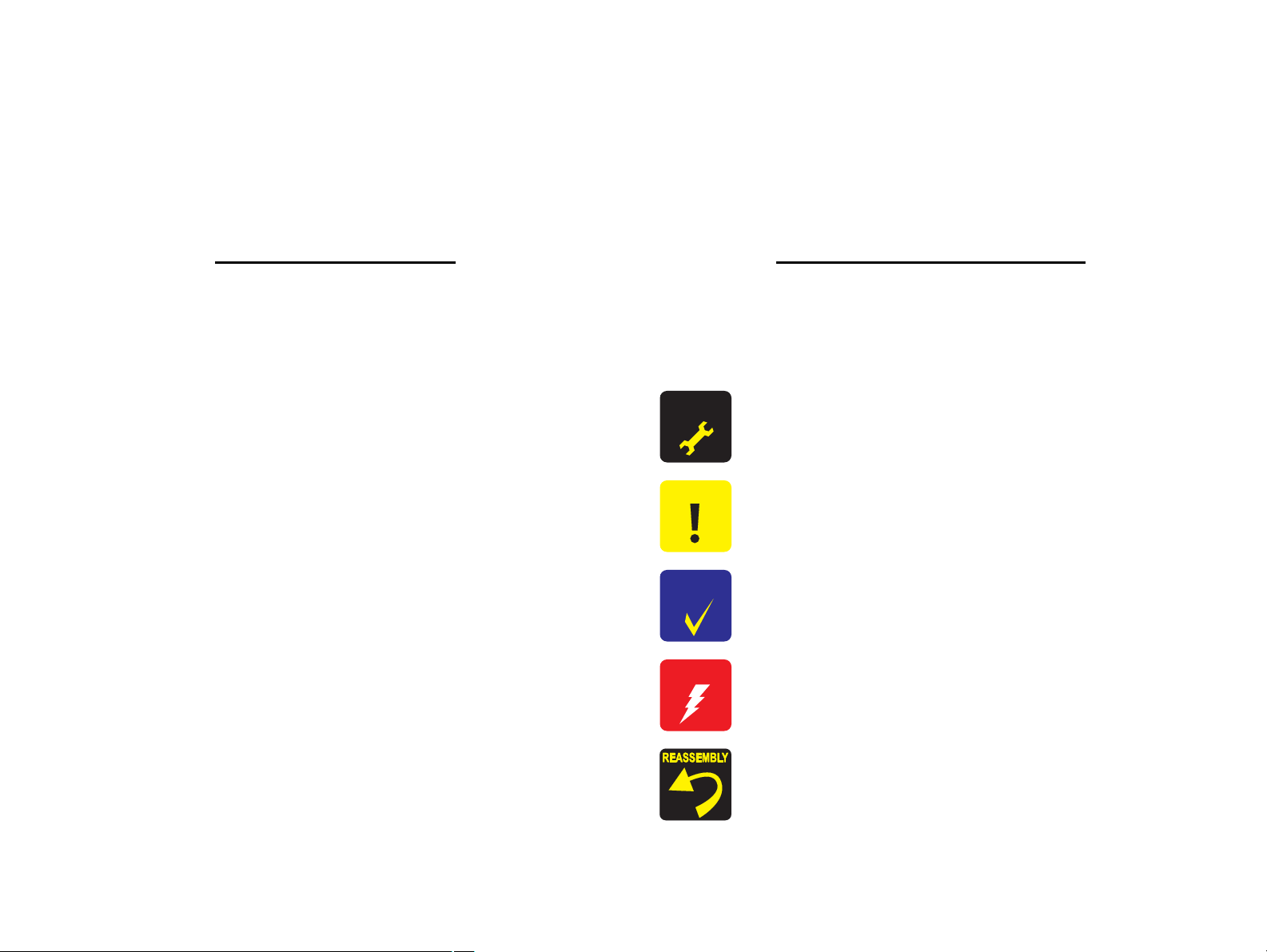
Indicates an operating or maintenance procedure, practice or condition
that is necessary to keep the product’s quality.
Indicates an operating or maintenance procedure, practice, or condition
that, if not strictly observed, could result in damage to, or destruction of,
equipment.
May indicate an operating or maintenance procedure, practice or
condition that is necessary to accomplish a task efficiently. It may also
provide additional information that is related to a specific subject, or
comment on the results achieved through a previous action.
Indicates an operating or maintenance procedure, practice or condition
that, if not strictly observed, could result in injury or loss of life.
Indicates that a particular task must be carried out according to a certain
standard after disassembly and before re-assembly, otherwise the
quality of the components in question may be adversely affected.
Page 5

Revision Status
Revision Date of Issue Description
A August 29, 2007 First Release
Page 6

EPSON Stylus CX9300F/CX9400Fax/DX9400F Revision A
Contents
Chapter 1 PRODUCT DESCRIPTION
1.1 Features................................................................................................................ 10
1.2 Printing Specifications......................................................................................... 11
1.2.1 Basic Specifications.................................................................................... 11
1.2.2 Ink Cartridge............................................................................................... 11
1.2.3 Print Mode .................................................................................................. 12
1.2.4 Supported Paper.......................................................................................... 14
1.2.5 Printing Area............................................................................................... 16
1.3 Scanner Specifications......................................................................................... 16
1.3.1 Scanning Range .......................................................................................... 17
1.4 General Specifications......................................................................................... 17
1.4.1 Electrical Specifications ............................................................................. 17
1.4.2 Environmental Conditions .......................................................................... 18
1.4.3 Durability.................................................................................................... 18
1.4.4 Acoustic Noise............................................................................................ 18
1.4.5 Safety Approvals (Safety standards/EMI) .................................................. 18
1.5 Interface............................................................................................................... 19
1.5.1 USB Interface ............................................................................................. 19
1.5.2 FAX Interface ............................................................................................. 19
1.5.3 Memory Card Slots..................................................................................... 20
1.6 Control Panel ....................................................................................................... 21
1.6.1 Operation Buttons & LEDs ........................................................................ 21
1.6.2 Control Panel Functions in Each Mode ...................................................... 23
1.7 Specification for Each Function .......................................................................... 25
1.7.1 Stand-alone Copy Function ........................................................................ 25
1.7.2 Memory Card Direct Print Function........................................................... 27
1.7.3 Camera Direct Print Function(USB Direct Print/PictBridge) .................... 31
1.7.4 Reprint/Restore Photos Function................................................................ 33
1.7.5 Setup Mode................................................................................................. 34
1.7.6 FAX Function ............................................................................................. 36
Chapter 2 OPERATING PRINCIPLES
2.1 Overview ............................................................................................................. 40
2.1.1 Printer Mechanism...................................................................................... 40
2.1.2 Motors & Sensors ....................................................................................... 41
2.2 Printer Mechanism Operating Principle .............................................................. 42
2.2.1 Printhead..................................................................................................... 42
2.2.2 Carriage Mechanism................................................................................... 44
2.2.3 Paper Loading/Paper Feed Mechanism ...................................................... 45
2.2.4 Ink System Mechanism .............................................................................. 50
2.2.5 Ink Sequence............................................................................................... 53
2.3 Scanner Mechanism ............................................................................................ 54
2.3.1 Scanner Carriage Mechanism..................................................................... 54
2.4 ADF Mechanism Operating Principle................................................................. 56
2.4.1 ADF Mechanism......................................................................................... 56
2.4.2 ADF Document Feed Mechanism .............................................................. 57
2.5 Electrical Circuit Operating Principles................................................................ 59
2.5.1 Power Supply Board................................................................................... 59
2.5.2 C696 Main Board ....................................................................................... 60
2.6 FAX Function Operating Principle ..................................................................... 66
2.6.1 Line Connection Function .......................................................................... 66
2.6.2 FAX Image Storing Function ..................................................................... 66
2.6.3 Communication Function ........................................................................... 67
2.6.4 Print Function ............................................................................................. 67
2.6.5 Save Setting Function................................................................................. 67
2.6.6 Data Recording Function............................................................................ 67
2.6.7 External Telephone Function...................................................................... 67
6
Page 7

EPSON Stylus CX9300F/CX9400Fax/DX9400F Revision A
Chapter 3 TROUBLESHOOTING
3.1 Overview ............................................................................................................. 69
3.1.1 Specified Tools ........................................................................................... 69
3.1.2 Preliminary Checks..................................................................................... 69
3.2 Troubleshooting................................................................................................... 70
3.2.1 Motor and Sensor Troubleshooting ............................................................ 70
3.3 Error Indications and Fault Occurrence Causes .................................................. 71
3.3.1 Error Message List...................................................................................... 71
3.3.2 Troubleshooting by Error Message ............................................................ 73
3.3.3 Superficial Phenomenon-Based Troubleshooting ...................................... 91
3.4 FAX Troubleshooting.......................................................................................... 98
3.4.1 FAX Log..................................................................................................... 98
3.4.2 Error Code/Superficial Phenomenon-Based Troubleshooting ................. 102
3.5 Fax Function/External Connection (EXT port) Function Check ...................... 104
3.5.1 Outline ...................................................................................................... 104
3.5.2 Fax Function and External Connection Function Check.......................... 104
Chapter 4 DISASSEMBLY/ASSEMBLY
4.1 Overview ........................................................................................................... 111
4.1.1 Precautions................................................................................................ 111
4.1.2 Tools ......................................................................................................... 111
4.1.3 Work Completion Check .......................................................................... 112
4.2 Disassembly Procedures.................................................................................... 113
4.3 Removing the Housing...................................................................................... 115
4.3.1 Paper Support Assy................................................................................... 115
4.3.2 Stacker Assy ............................................................................................. 115
4.3.3 Scanner Unit/ADF Unit ............................................................................ 116
4.3.4 Upper Housing.......................................................................................... 119
4.3.5 Front Housing ........................................................................................... 120
4.4 Removing the Circuit Boards ............................................................................ 121
4.4.1 Main Board Unit ....................................................................................... 121
4.4.2 Panel Unit ................................................................................................. 124
4.4.3 Power Supply Unit.................................................................................... 126
4.5 Disassembling the Printer Mechanism .............................................................. 127
4.5.1 Printhead ................................................................................................... 127
4.5.2 CR Scale ................................................................................................... 130
4.5.3 Hopper ...................................................................................................... 131
4.5.4 Removing the Printer Mechanism (Lower Housing)/Card Slot Cover .... 132
4.5.5 Left Frame ................................................................................................ 134
4.5.6 Front Frame/Right Frame ......................................................................... 135
4.5.7 Star Wheel Holder Assy ........................................................................... 137
4.5.8 EJ Roller ................................................................................................... 137
4.5.9 PF Encoder Sensor.................................................................................... 138
4.5.10 PF Scale .................................................................................................. 139
4.5.11 PF Motor................................................................................................. 140
4.5.12 CR Motor................................................................................................ 141
4.5.13 Main Frame Assy.................................................................................... 143
4.5.14 CR Unit................................................................................................... 145
4.5.15 Upper Paper Guide ................................................................................. 147
4.5.16 ASF Unit................................................................................................. 147
4.5.17 Ink System Unit ...................................................................................... 149
4.5.18 Front Paper Guide................................................................................... 151
4.5.19 PF Roller................................................................................................. 153
4.5.20 Waste Ink Pads ....................................................................................... 154
4.6 Disassembling the Scanner Unit........................................................................ 155
4.6.1 Separating the Scanner Unit and the ADF Unit ....................................... 155
4.6.2 Upper Scanner Housing............................................................................ 156
4.6.3 Scanner Carriage Unit .............................................................................. 157
4.6.4 Scanner Motor Unit .................................................................................. 159
4.7 Disassembling the ADF Unit ............................................................................ 160
4.7.1 ADF Hinge ............................................................................................... 160
4.7.2 ADF Cover Assy ...................................................................................... 161
4.7.3 ADF Paper Support Assy ......................................................................... 161
4.7.4 ADF Motor Unit ....................................................................................... 162
4.7.5 ADF Frame Assy ...................................................................................... 164
4.7.6 ADF Front Cover...................................................................................... 165
4.7.7 ADF Driven Roller ................................................................................... 165
4.7.8 ADF PF Roller.......................................................................................... 166
7
Page 8

EPSON Stylus CX9300F/CX9400Fax/DX9400F Revision A
Chapter 5 ADJUSTMENT
5.1 Adjustment Items and Overview....................................................................... 168
5.1.1 Servicing Adjustment Item List................................................................ 168
5.1.2 Required Adjustments .............................................................................. 170
5.2 Using the Adjustment Program ......................................................................... 172
5.2.1 TOP Margin Adjustment .......................................................................... 172
5.2.2 First Dot Position Adjustment .................................................................. 172
5.2.3 Head Angular Adjustment ........................................................................ 173
5.2.4 Bi-D Adjustment....................................................................................... 174
5.2.5 PF Adjustment .......................................................................................... 174
5.2.6 PF Band Adjustment................................................................................. 175
5.2.7 Bottom Margin Adjustment...................................................................... 176
Chapter 6 MAINTENANCE
6.1 Overview ........................................................................................................... 178
6.1.1 Cleaning.................................................................................................... 178
6.1.2 Service Maintenance................................................................................. 178
6.1.3 Lubrication................................................................................................ 179
Chapter 7 APPENDIX
7.1 Exploded Diagram / Parts List .......................................................................... 185
7.2 Electrical Circuits .............................................................................................. 185
8
Page 9

PRODUCT DESCRIPTION
CHAPTER
1
Page 10
EPSON Stylus CX9300F/CX9400Fax/DX9400F Revision A
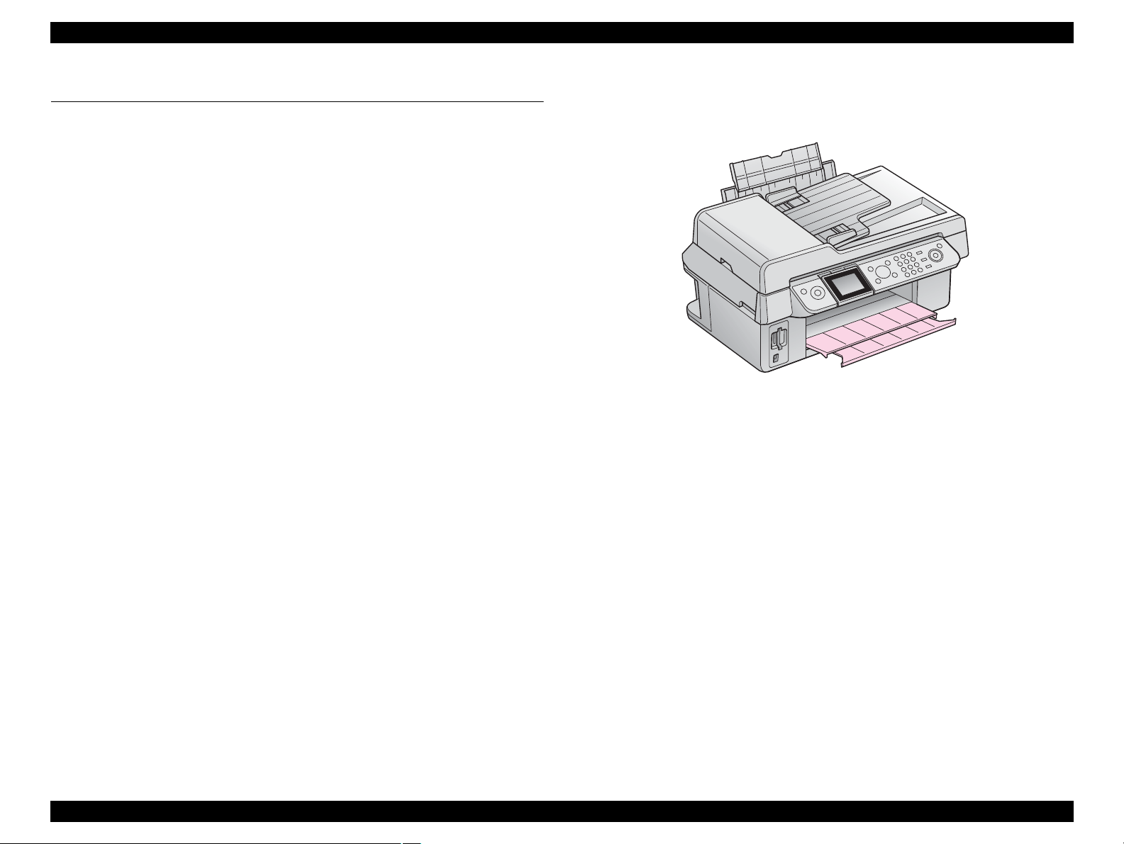
1.1 Features
EPSON Stylus CX9300F/CX9400Fax/DX9400F are color ink-jet printers with scanner
and FAX functions, and have the following features.
Available Functions
Printer
Printing from a computer or directly printing from a memory card
Scanner
Scanning from a computer
Copy
Stand alone copy using the scanning and printing functions
Memory card slot
Available as memory card reader for PC
FAX
Sending/receiving fax
Color LCD
2.5-inch color TFT LCD
ADF
Continuous scanning using an ADF
High speed & High quality
Maximum print resolution: SMGA 5760 (H) x 1440 (V) dpi
D4-chips Turbo II print head achieves higher print speed than ever.
(Black: 90 nozzles x 1, Color: 90 nozzles x 1 per color)
Four independent ink cartridges is installed.
Newly developed pigment ink is employed.
Borderless printing on specified EPSON brand paper is available.
Dimensions
Dimensions: 460 mm (W) x 410 mm (D) x 236 mm (H)
(Paper support and stacker are closed. Rubber feet are included)
Weight: 7.6 kg
(Ink cartridge and power cable are excluded)
Figure 1-1. External View
PRODUCT DESCRIPTION Features 10
Page 11
EPSON Stylus CX9300F/CX9400Fax/DX9400F Revision A
C A U T I O N
1.2 Printing Specifications
1.2.1 Basic Specifications
Table 1-1. Printer Specifications
Item Specification
Print method On-demand ink jet
Nozzle configuration
Print direction Bi-directional minimum distance printing, Unidirectional printing
Print resolution
Control code
Input buffer size 64 Kbytes
Paper feed method Friction feed, using the ASF (Auto Sheet Feeder)
Paper path Top feed, front out
Paper feed rates T.B.D. mm/sec (at 25.4 mm feed)
PF interval Programmable in 0.01764 mm (1/1440 inch) steps
Black: 90 nozzles x 1
Color: 90 nozzles x 3 (Cyan, Magenta, Yellow)
Horizontal x Vertical (dpi)
• 360 x 120 • 1440 x 720
• 360 x 360 • 1440 x 1440
• 360 x 720 • SMGA 5760 x 1440 (2880 x 1440)
• 720 x 720
• ESC/P Raster command
• ESC/P-R (RGB) command
• EPSON Remote command
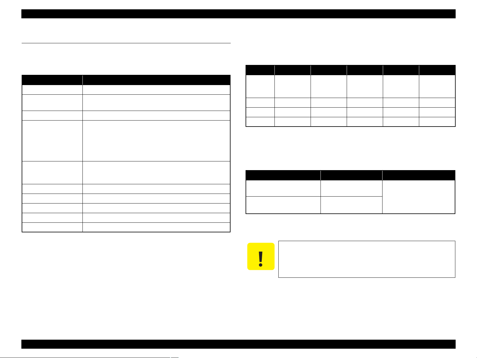
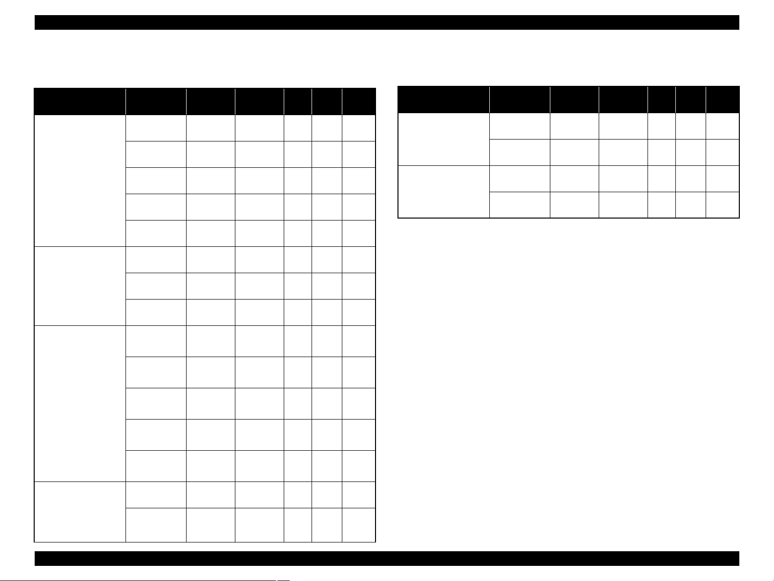
1.2.2 Ink Cartridge
The product numbers of the EPSON ink cartridges for this printer are shown below.
Table 1-2. Product No. of Ink Cartridges
Color EAI Latin Euro CISMEA Asia
Black
Cyan T0692 (3S) T0732 (3S) T0712 (3S) T0732 (3S) T0732 (3S)
Magenta T0693 (3S) T0733 (3S) T0713 (3S) T0733 (3S) T0733 (3S)
Yellow T0694 (3S) T0734 (3S) T0714 (3S) T0734 (3S) T0734 (3S)
T0681 (S)
T0691 (2S)
Shelf life
Two years from production date (if unopened), six months after opening package.
Storage Temperature
Situation Storage Temperature Limit
When stored in individual boxes
When installed in main unit
Dimension
12.7 mm (W) x 68 mm (D) x 47 mm (H)
T0731H (S)
T0731 (2S)
T0901 (3S)
T0711H (S)
T0711 (2S)
T0731H (S)
T0731 (2S)
Table 1-3. Storage Temperature
-20 oC to 40 oC
(-4oF to 104oF)
-20 oC to 40 oC
(-4oF to 104oF)
1 month max. at 40 oC (104oF)
T0731 (2S)
Do not use expired ink cartridges.
The ink in the ink cartridge freezes at -16 °C (3.2 oF). It takes
about three hours under 25 °C (77
o
F) until the ink thaws and
becomes usable.
PRODUCT DESCRIPTION Printing Specifications 11
Page 12
EPSON Stylus CX9300F/CX9400Fax/DX9400F Revision A
1.2.3 Print Mode
Media Print Mode
• Plain paper
• Premium Bright
White Paper (EAI)
• Premium Bright
White Inkjet Paper
(others)
• Ultra Premium
Glossy Photo Paper
(EAI)
• Ultra Glossy Photo
Paper (others)
• Photo Paper Glossy
(EAI)
• Glossy Photo Paper
(others)
• Premium Photo
Paper Glossy (EAI)
• Premium Glossy
Photo Paper (others)
• Premium Photo
Paper Semi-Gloss
(EAI)
• Premium Semigloss
Photo Paper (other)
Table 1-4. Print Mode (Color)
Resolution
(H x V dpi)
Fast Economy
Economy
Draft 360x120
Normal 360x360
Fine (360) 360x720
Fine (720) 720x720
Photo (1440) 1440x720
Photo2 (1440) 1440x1440
Photo (5760) 2880x1440
Photo Draft 360x720
Photo (720) 720x720
Photo (1440) 1440x720
Photo2 (1440) 1440x1440
Photo (5760) 2880x1440
/
360x120
Dot Size
(cps)
Eco
(400cps)
Eco
(400cps)
VSD1
(245cps)
VSD2
(285cps)
VSD3
(285cps)
VSD3
(285cps)
VSD3
(285cps)
VSD3
(285cps)
VSD1
(245cps)
VSD2
(285cps)
VSD3
(285cps)
VSD3
(285cps)
VSD3
(285cps)
Micro
Bi-d
Weave
ON OFF
ON OFF
ON OFF
ON ON
ON ON
ON ON
ON ON
ON ON
ON ON
ON ON
ON ON
ON ON
ON ON
Border-
less
N/A
N/A
N/A
N/A
N/A
OK
OK
OK
N/A
OK
OK
OK
OK
Media Print Mode
• Photo Quality Inkjet
Paper* (others)
Photo (1440) 1440x720
Envelope
Note* : Not supported in EAI.
Table 1-4. Print Mode (Color)
Resolution
(H x V dpi)
Photo (720) 720x720
Normal 360x360
Fine (720) 720x720
Dot Size
VSD2
(285cps)
VSD3
(285cps)
VSD1
(245cps)
VSD3
(285cps)
(cps)
Micro
Bi-d
Weave
ON ON
ON ON
OFF OFF
OFF ON
Border-
less
N/A
N/A
N/A
N/A
• Premium
Presentation Paper
Matte (EAI)
• Matte Paper Heavyweight (others)
Photo (720) 720x720
Photo (1440) 1440x720
VSD2
(285cps)
VSD3
(285cps)
ON ON
ON ON
OK
OK
PRODUCT DESCRIPTION Printing Specifications 12
Page 13
EPSON Stylus CX9300F/CX9400Fax/DX9400F Revision A
Media Print Mode
• Plain paper
• Premium Bright
White Paper (EAI)
• Premium Bright
White Inkjet Paper
(others)
• Ultra Premium
Glossy Photo Paper
(EAI)
• Ultra Glossy Photo
Paper (others)
• Photo Paper Glossy
(EAI)
• Glossy Photo Paper
(others)
• Premium Photo
Paper Glossy (EAI)
• Premium Glossy
Photo Paper (others)
• Premium Photo
Paper Semi-Gloss
(EAI)
• Premium Semigloss
Photo Paper (other)
Table 1-5. Print Mode (Monochrome)
Resolution
(H x V dpi)
Fast Economy
Economy
Draft 360x120
Normal 360x360
Fine (360) 360x720
Fine (720) 720x720
Photo (1440) 1440x720
Photo2 (1440) 1440x1440
Photo (5760) 2880x1440
Photo Draft 360x720
Photo (720) 720x720
Photo (1440) 1440x720
Photo2 (1440) 1440x1440
Photo (5760) 2880x1440
/
360x120
Dot Size
(cps)
Eco
(400cps)
Eco
(400cps)
VSD1
(245cps)
VSD2
(285cps)
VSD3
(285cps)
VSD3
(285cps)
VSD3
(285cps)
VSD3
(285cps)
VSD1
(245cps)
VSD2
(285cps)
VSD3
(285cps)
VSD3
(285cps)
VSD3
(285cps)
Micro
Bi-d
Weave
ON OFF
ON OFF
ON OFF
ON ON
ON ON
ON ON
ON ON
ON ON
ON ON
ON ON
ON ON
ON ON
ON ON
Border-
less
N/A
N/A
N/A
N/A
N/A
OK
OK
OK
OK
OK
OK
OK
OK
Table 1-5. Print Mode (Monochrome)
Media Print Mode
• Photo Quality Inkjet
Paper* (others)
Photo (1440) 1440x720
Envelope
Note* : Not supported in EAI.
Resolution
(H x V dpi)
Photo (720) 720x720
Normal 360x360
Fine (720) 360x720
Dot Size
(cps)
VSD2
(285cps)
VSD3
(285cps)
VSD1
(320cps)
VSD3
(285cps)
Micro
Bi-d
Weave
ON ON
ON ON
OFF OFF
OFF ON
Border-
less
N/A
N/A
N/A
N/A
• Premium
Presentation Paper
Matte (EAI)
• Matte Paper Heavyweight (others)
Photo (720) 720x720
Photo (1440) 1440x720
VSD2
(285cps)
VSD3
(285cps)
ON ON
ON ON
OK
OK
PRODUCT DESCRIPTION Printing Specifications 13
Page 14
EPSON Stylus CX9300F/CX9400Fax/DX9400F Revision A
C A U T I O N
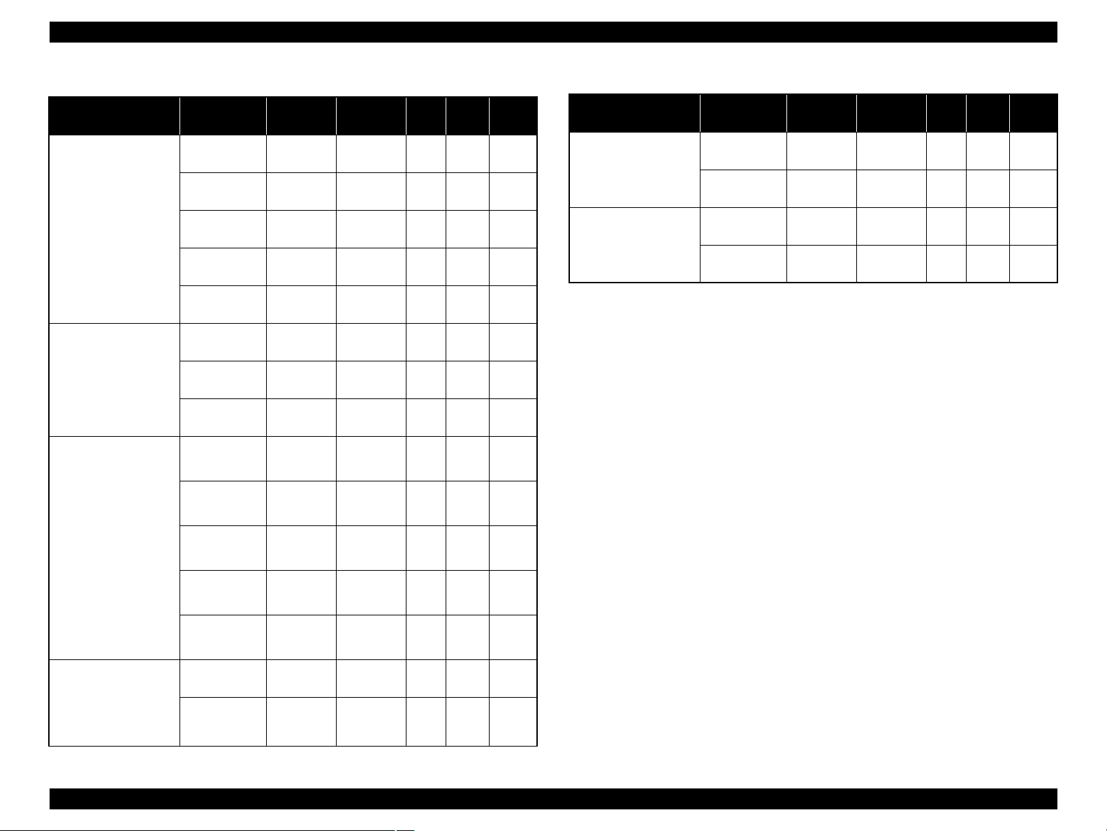
1.2.4 Supported Paper
The table below lists the paper type and sizes supported by the printer. The supported paper type and sizes vary depending on destinations (between EAI, EUR, and Asia).
Table 1-6. Supported Paper
Paper Name Paper Size
Thickness
(mm)
Legal 215.9 x 355.6 mm (8.5”x14”)
Letter 215.9 x 279.4 mm (8.5”x11”) Y - Y - Y -
A4 210 x 297 mm (8.3”x11.7”) Y - Y - Y -
B5 182 x 257 mm (7.2”x10.1”) - - Y - Y -
Plain paper
A5 148 x 210 mm (5.8”x8.3”) - - Y - Y -
0.08-0.11
Half Letter 139.7 x 215.9 mm (5.5”x8.5”) Y - - - - -
A6 105 x 148 mm (4.2”x5.8”) Y - Y - Y -
User Defined
89 x 127- 329 x 1117.6 mm
(3.56”x 5.08” - 13.16”x44.7”)
Premium Inkjet Plain Paper A4 210 x 297 mm (8.3”x11.7”) 0.11
Letter 215.9 x 279.4 mm (8.5”x11”) 0.11
Premium Bright White Paper (EAI)
Bright White Inkjet Paper (Euro, Asia)
A4 210 x 297 mm (8.3”x11.7”) 0.13
Letter 215.9 x 279.4 mm (8.5”x11”)
Weight
64-90 g/m
(17-24 lb.)
80 g/m
(21 lb.)
90 g/m
(24 lb.)
92.5 g/m
(25 lb.)
EAI EUR Asia
*1
*2
P
B
*1
P
Y - Y - Y -
2
Y - Y - Y -
2
- - Y - Y -
2
Y - - - - -
2
- - Y - Y -
Y Y - - - -
*2
*1
B
P
*2
B
A4 210 x 297 mm (8.3”x11.7”) - - Y Y Y Y
Ultra Premium Glossy Photo Paper (EAI)
Ultra Glossy Photo Paper (Euro, Asia)
8” x 10” 203.2 x 254 mm Y Y - - - -
5” x 7” 127 x 178 mm Y Y Y Y - -
4” x 6” 101.6 x 152.4 mm Y Y Y Y Y Y
Note *1 : “Y” in the “P” column stands for “the paper type/size is Supported”.
*2 : “Y” in the “B” column stands for “Borderless printing is available”.
PRODUCT DESCRIPTION Printing Specifications 14
0.30
290 g/m
2
(77 lb.)
Make sure the paper is not wrinkled, fluffed, torn, or folded.
The curve of paper must be 5 mm or below.
When printing on an envelope, be sure the flap is folded neatly.
Do not use the adhesive envelopes.
Do not use double envelopes and cellophane window envelopes.
Page 15
EPSON Stylus CX9300F/CX9400Fax/DX9400F Revision A
C A U T I O N
Table 1-6. Supported Paper
Paper Name Paper Size
Thickness
(mm)
Letter 215.9 x 279.4 mm (8.5”x11”)
A4 210 x 297 mm (8.3”x11.7”) Y Y Y Y Y Y
Premium Photo Paper Glossy (EAI)
Premium Glossy Photo Paper (Euro, Asia)
8” x 10” 203.2 x 254 mm Y Y - - - -
0.27
5” x 7” 127 x 178 mm Y Y Y Y Y Y
4” x 6
”
101.6 x 152.4 mm Y Y Y Y Y Y
16:9 wide 101.6 x 180.6 mm Y Y Y Y Y Y
Letter 215.9 x 279.4 mm (8.5”x11”)
Photo Paper Glossy (EAI)
Glossy Photo Paper (Euro, Asia)
A4 210 x 297 mm (8.3”x11.7”) Y Y Y Y Y Y
0.25
5” x 7” 127 x 178 mm - - Y Y - -
4” x 6” 101.6 x 152.4 mm Y Y Y Y Y Y
Letter 215.9 x 279.4 mm (8.5”x11”)
Premium Photo Paper Semi-Gloss (EAI)
Premium Semigloss Photo Paper (Euro, Asia)
A4 210 x 297 mm (8.3”x11.7”) - - Y Y Y Y
0.27
4” x 6” 101.6 x 152.4 mm Y Y Y Y Y Y
Letter 215.9 x 279.4 mm (8.5”x11”)
Premium Presentation Paper Matte (EAI)
Matte Paper-Heavyweight (Euro, Asia)
A4 210 x 297 mm (8.3”x11.7”) - - Y Y Y Y
0.23
8” x 10” 203.2 x 254 mm Y Y - - - -
Photo Quality Inkjet Paper A4 210 x 297 mm (8.3”x11.7”) 0.13
Weight
255 g/m
(68 lb.)
258 g/m
(68 lb.)
250 g/m
(66 lb.)
167 g/m
(44 lb.)
102 g/m
(27 lb.)
EAI EUR Asia
*1
*2
P
B
*1
P
B
Y Y - - - -
2
Y Y - - - -
2
Y Y - - - -
2
Y Y - - - -
2
2
- - Y - Y -
*2
*1
P
*2
B
#10 104.8 x 241.3 mm (4.125”x9.5”)
Envelopes
#DL 110 x 220 mm - - Y - Y -
#C6 114 x 162 mm - - Y - Y -
Note *1 : “Y” in the “P” column stands for “the paper type/size is Supported”.
*2 : “Y” in the “B” column stands for “Borderless printing is available”.
PRODUCT DESCRIPTION Printing Specifications 15
Y - Y - Y -
-
75-100 g/m
(20-27 lb.)
2
Make sure the paper is not wrinkled, fluffed, torn, or folded.
The curve of paper must be 5 mm or below.
When printing on an envelope, be sure the flap is folded neatly.
Do not use the adhesive envelopes.
Do not use double envelopes and cellophane window envelopes.
Page 16
EPSON Stylus CX9300F/CX9400Fax/DX9400F Revision A
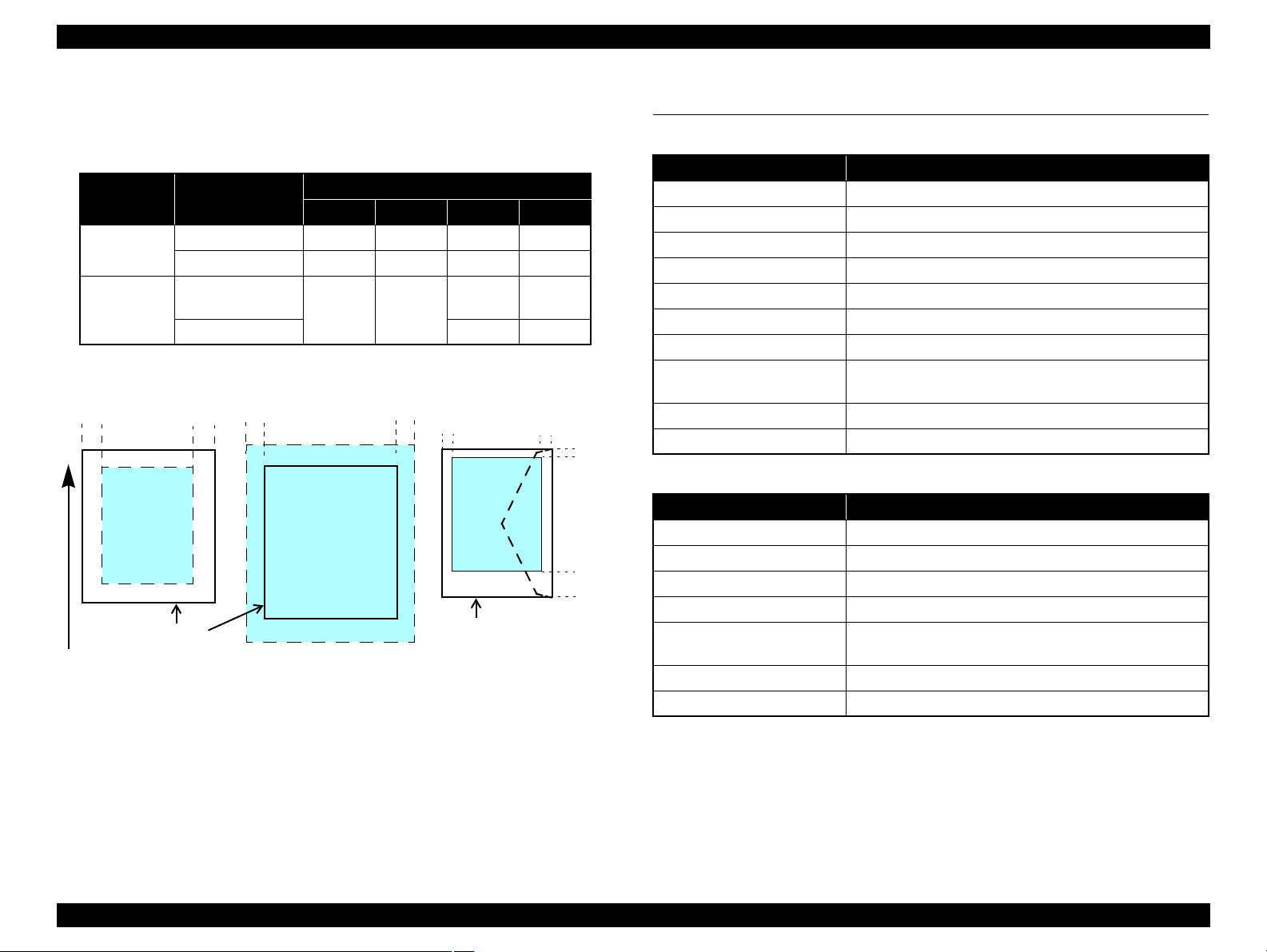
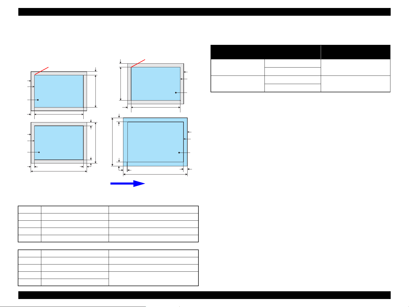
Print Area
LM RM
TM
BM
BM
Cut Sheet (Standard)
Cut Sheet (Borderless)
Paper SIze
LM
RM
TM
BM
Print Area
LM RM
Print Area
Envelope
Paper Size
TM
Paper Feed Direction
1.2.5 Printing Area
The printing area for this printer is shown below.
Table 1-7. Printing Area (Margins)
Margin
2.96 mm* 3.39 mm*
2.82 mm* 3.39 mm*
Print Mode Paper Size
Standard print
Borderless
print
Note * : The margins for Borderless print are margins that bleed off the edges of paper.
Any size
Envelope
A4/Letter to
5” x 7” / Hi-Vision
4” x 6”
Figure 1-2. Printing Area
Left Right Top Bottom
3 mm 3 mm 3 mm 3 mm
5 mm 5 mm 3 mm 20 mm
2.54 mm* 2.54 mm*
1.3 Scanner Specifications
Table 1-8. Basic Specifications
Item Specification
Scanner type Flatbed, color
Scanning method Moving carriage, stationary document
Home position The rear left corner
Photoelectric device CIS
Light source LED
Maximum document sizes A4 or US letter
Scanning range 8.5” x 11.7” (216 mm x 297 mm)
Maximum resolution
Maximum effective pixels 10,200 x 14,040 pixels (CIS optical resolution x Microstep drive)
Pixel depth 16 bit per pixel (input) and 8 bit per pixel (output).
Item Specification
Document loading Face-up
Maximum document sizes A4 or US letter or Legal
Supported paper type Plain paper only
Paper thickness 60 to 95 g/m
Maximum number of
documents which can be set
Document path Feeds from upper tray and ejects to lower tray
Document set position Center of document tray
Main scan: 1200 dpi
Sub scan: 2400 dpi
Table 1-9. ADF Specifications
2
30 sheets (Xerox-P 64 g/m2) or 3mm (A4,US Letter) / 10
sheet (Legal)
PRODUCT DESCRIPTION Scanner Specifications 16
Page 17
EPSON Stylus CX9300F/CX9400Fax/DX9400F Revision A
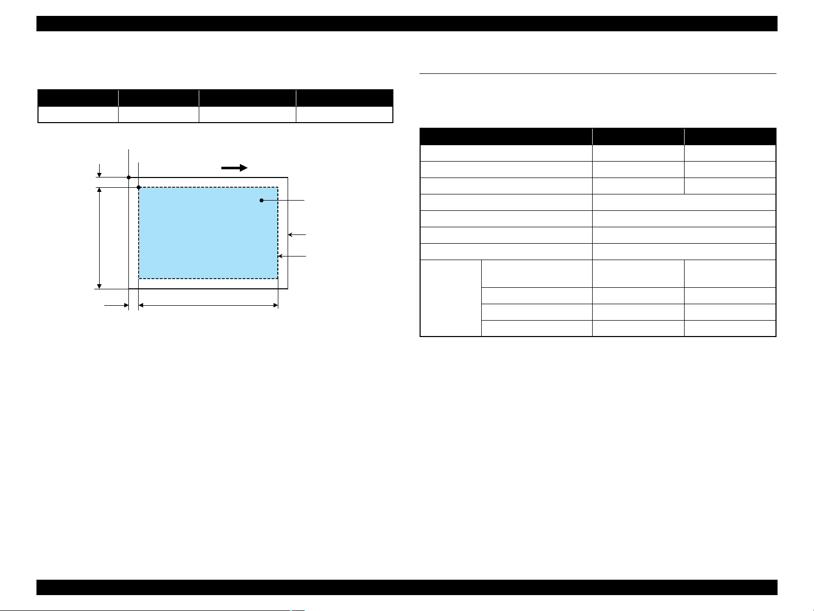
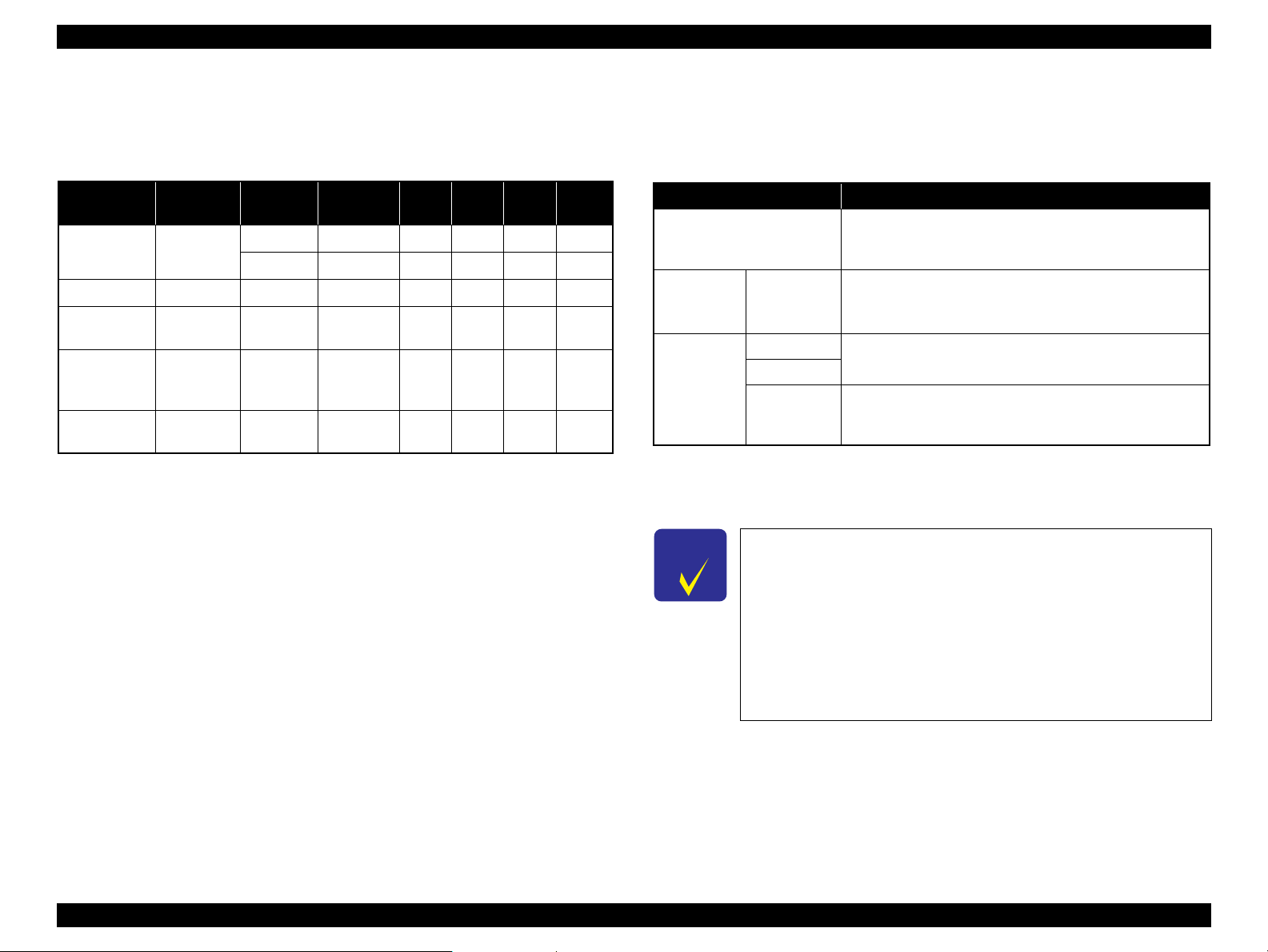
a
RW
RL
OTM
OLM
Scanning start position
Home position
Scanning range
Scan bed
Original
(face down)
Scanning direction
1.3.1 Scanning Range
Table 1-10. Scanning Range
RL (read length) RW (read width) OLM (left margin) OTM (top margin)
297 mm 216 mm 1.5 mm 1.5 mm
Figure 1-3. Scanning Range
1.4 General Specifications
1.4.1 Electrical Specifications
Table 1-11. Primary Power Specifications
Item 100-120 V model 220-240 V model
Rated power supply voltage 100 to 120 VAC 220 to 240 VAC
Input voltage range 90 to 132 VAC 198 to 264 VAC
Rated current (Max. rated current) T.B.D. A (T.B.D. A) T.B.D. A (T.B.D. A)
Rated frequency 50 to 60 Hz
Input frequency range 49.5 to 60.5 Hz
Insulation resistance 3000 V (for one minute)
Energy conservation International Energy Star Program compliant
Printing
(ISO10561 Letter Pattern)
Power
consumption
Note 1: If the printer or scanner is not operated for more than three minutes, the printer goes
into the power save mode within five minutes.
2: When no operation is made with the control panel for more than 13 minutes, the panel
goes to the power save mode within 15 minutes.
Low-power mode T.B.D. W T.B.D. W
Sleep mode T.B.D. W T.B.D. W
Standby mode (power-off) T.B.D. W T.B.D. W
T.B.D. W T.B.D. W
PRODUCT DESCRIPTION General Specifications 17
Page 18
EPSON Stylus CX9300F/CX9400Fax/DX9400F Revision A
C A U T I O N
10/50
27/80
35/9520/68
Temperature (°C/°F)
20
30
40
50
90
80
70
60
Humidity (%)
30/86 40/104
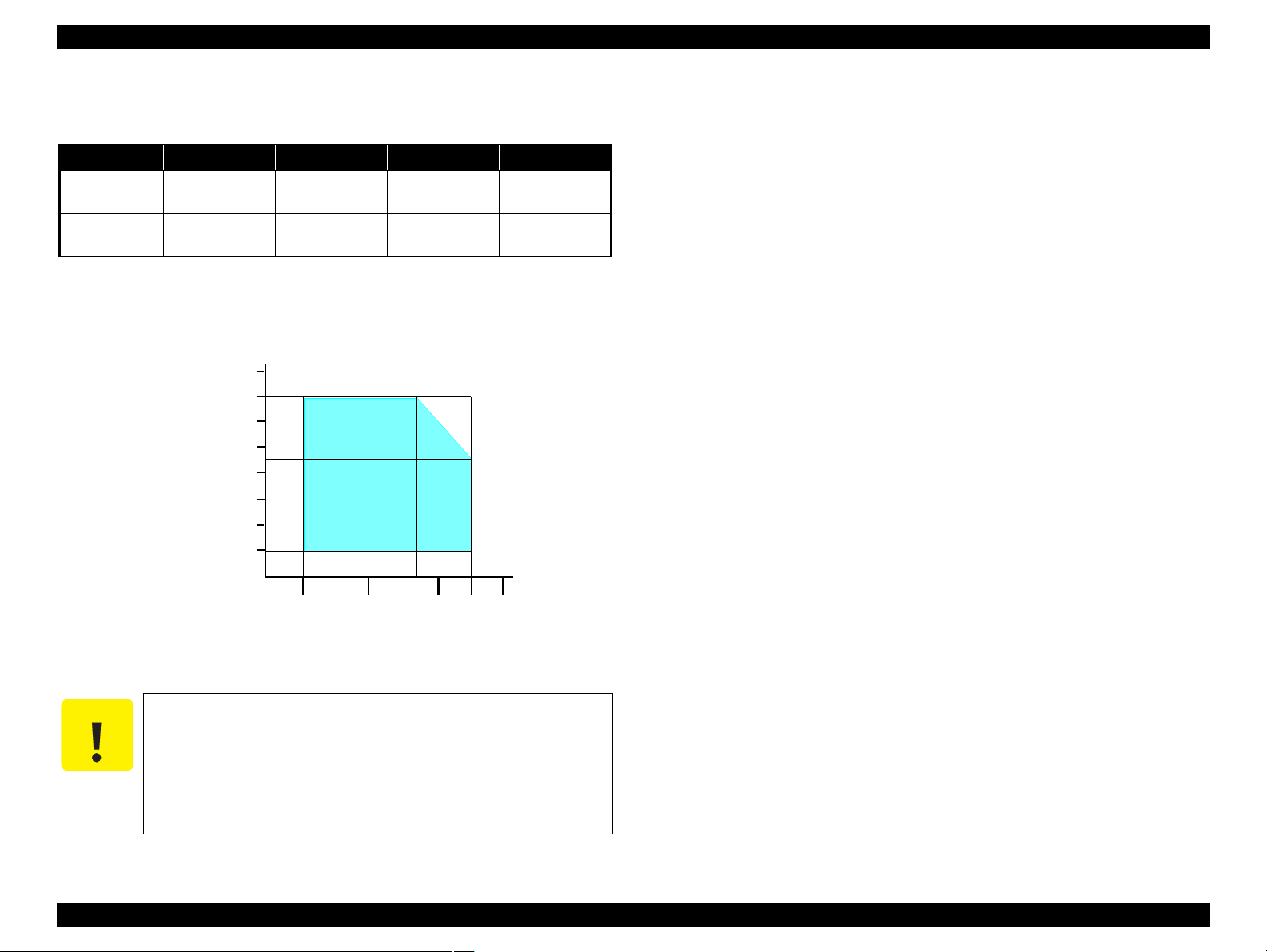
1.4.2 Environmental Conditions
Table 1-12. Environmental Conditions
°F)
*1
3
Humidity
20 to 80%
Condition Temperature
Operating
Storage
(unpacked)
Note *1 : The combined Temperature and Humidity conditions must be within the blue-shaded
range in
*2 : N o condensation
*3 : Must be less than 1 month at 40°C.
10 to 35°C
(50 to 95
-20 to 40°C*
(-4°F to 104°F)
Fig.1-4.
Figure 1-4. Temperature/Humidity Range
When returning the repaired printer to the customer, make sure
the Printhead is covered with the cap and the ink cartridge is
installed.
If the Printhead is not covered with the cap when the printer is
off, turn on the printer with the ink cartridge installed, make
sure the Printhead is covered with the cap, and then turn the
printer off.
5 to 85%
*1,2
Shock Vibration
1G
(1 msec or less)
2G
(2 msec or less)
10
10
0.15G,
to 55Hz
0.50G,
to 55Hz
1.4.3 Durability
Total print life: Black 20,000 pages (A4, 3.5% duty),
Color 10,000 pages (A4, ISO FDC24712),
or five years whichever comes first
Printhead: Five billions shots (per nozzle) or five years whichever
comes first
Scanner carriage: 30,000 cycles of carriage movement
Total ADF feeding: 10,000 pages
1.4.4 Acoustic Noise
T.B.D. dB
(when printing from PC, on Premium Glossy Photo Paper, in highest quality)
T.B.D. dB (when scanning, default setting)
1.4.5 Safety Approvals (Safety standards/EMI)
USA UL60950-1
FCC Part15 Subpart B Class B
Canada CSA No.60950-1
CAN/CSA-CEI/IEC CISPR 22 Class B
Mexico NOM-019-SCFI-1998
Taiwan CNS13438 Class B
CNS14336
EU EN60950-1
EN55022 Class B
EN61000-3-2, EN61000-3-3
EN55024
Germany EN60950-1
Russia GOST-R (IEC60950-1, CISPR 22)
Singapore IEC60950-1
Korea K60950-1
KN22 Class B
KN61000-4-2/-3/-4/-5/-6/-11
China GB4943
GB9254 Class B, GB17625.1
Hong Kong IEC60950-1
Argentina IEC60950-1
Australia AS/NZS CISPR22 Class B
PRODUCT DESCRIPTION General Specifications 18
Page 19

EPSON Stylus CX9300F/CX9400Fax/DX9400F Revision A
1.5 Interface
This printer has USB interface and memory card slots of the following specifications.
1.5.1 USB Interface
The table below describes the specifications of the two USB ports; USB device port for
connecting with a host such as a computer, and the USB host port for connecting with
an external devices such as a DSC (digital still camera).
Table 1-13. USB Interface Specifications
Item USB Device port USB Host port*
• Universal Serial Bus
Specifications Revision 2.0
Compatible standards
Transfer rate
• Universal Serial Bus Device
Class Definition for Printing
Devices Version 1.1
480 Mbps (High Speed) 12 Mbps (Full Speed)
Data format
Compatible connector
Max. cable length
Note* : External devices that can be connected to the USB device port are:
DSC compliant with the USB Direct Print Protocol specification Rev 1.0
DSC compliant with the CIPA DC-001-2003 (PictBridge) specifications
USB Series B USB Series A
• Universal Serial Bus
Specifications Revision 2.0
• Universal Serial Bus Mass
Storage Class Bulk-Only
Transport Revision 1.0
NRZI
2 [m] or less
The “Model Name” is replaced as shown in the following table.
Table 1-15. Model Names Indicated in the Device ID
Destination Model Name
North America Stylus CX9400Fax
Euro Stylus DX9400F
Asia/Pacific Stylus CX9300F
1.5.2 FAX Interface
Port Name Connector Description
Line port RJ11 Connects to phone cable from modular wall jack.
EXT port RJ11 Connects to TAM or Telephone.
Table 1-14. Device ID
When IEEE 1284.4 is Enabled When IEEE 1284.4 is Disabled
MFG:EPSON;
CMD:ESCPL2,BDC,D4,D4PX,ESCPR1;
MDL:Model Name;
CLS:PRINTER;
DES:EPSON[SP]Model Name;
MFG:EPSON;
CMD:ESCPL2,BDC,ESCPR1;
MDL:Model Name;
CLS:PRINTER;
DES:EPSON[SP]Model Name;
PRODUCT DESCRIPTION Interface 19
Page 20
EPSON Stylus CX9300F/CX9400Fax/DX9400F Revision A
1.5.3 Memory Card Slots
Table 1-16. List of Supported Memory Card
Priority
1
2
Slot Compatible memory card Standard
Memory Stick/
Memory Stick
PRO
SD/MMC SD (Security Digital) SD Memory Card Specifications / PART1. Physical Layer Specification Ver. 2.0
xD-Picture card xD-Picture card xD-Picture Card Specification Ver.1.20 compatible 2GB Type M/H supported
CF Type II Compact Flash CF+ and CompactFlash Specification Revision 3.0 compatible 4GB True-IDE compatible memory card only
Memory Stick “MemoryStick Standard” Format Specification Ver.1.42-00 compatible 128MB Includes versions with memory select function
MagicGate Memory Stick 128MB Copy protection function is not supported
MagicGate Memory Stick Duo An adapter should be used
Memory Stick PRO Memory Stick PRO Format Specifications-without security specifications Ver.1.02-00
compatible
Memory Stick Duo MemoryStick Duo Format Specification Ver.1.11-00 compatible
Memory Stick Pro Duo MemoryStick PRO Duo Format Specification Ver.1.02-00 compatible
Memory Stick micro Memory Stick Micro Format Specification Ver.1.02-00 compatible The Memory Stick adapter for standard size
miniSD/microSD
SDHC
miniSDHC/microSDHC
MultiMediaCard MultiMediaCard Standard Ver. 4.1 compatible 64MB
Microdrive
compatible
Max.
capacity
4GB
2GB
4GB
Remarks
Copy protection function is not supported
The Memory Stick Duo adapter should be
used
The Memory Stick Duo adapter should be
used.
should be used.
The SD adapter should be used
Speed Class is not supported
The SD adapter should be used
Speed Class is not supported
Note: • Memory Stick/PRO, SD/MMC and xD-Picture Card shares the same slot.
• When cards are inserted in the two slots at once, the slot which will be accessed first is determined according to the priority shown in the table.
• To select a card that has been inserted in a non-active slot, first remove the card in the active slot.
• In memory card direct printing mode, the image files in the active slot are valid and have assigned frame numbers. The number of images will not change if a card is inserted in another
nonselected slot.
• When the card inserted in the slot is accessed from the PC, only one drive is displayed at a time as a removable disk* and only the card that is in the active slot can be accessed via the
removable disk. A card that has been inserted into a non-selected slot cannot be accessed.
(This is for Windows. For Macintosh, the card in the active slot will be mounted on the desktop.)
• Does not support 5V type of memory cards.
• When a memory card is being accessed, do not touch the memory card.
• For detailed information on the supported file system and formatting the memory card, refer to “ 1.7.2 Memory Card Direct Print Function ( p. 27 ) ”.
PRODUCT DESCRIPTION Interface 20
Page 21
EPSON Stylus CX9300F/CX9400Fax/DX9400F Revision A
LCD
Power
button
Copy button
Memory Card button
Photo button FAX button
Setup button Display/Crop button
Cross Key and OK button
Menu button Back button
Start button
Stop/Clear Settings button
Ten keys
Auto Answer/Space button
Speed Dial/Back Space button
Redial/Pause button
Auto Answer LED
Power LED
Mode LED
Mode LED
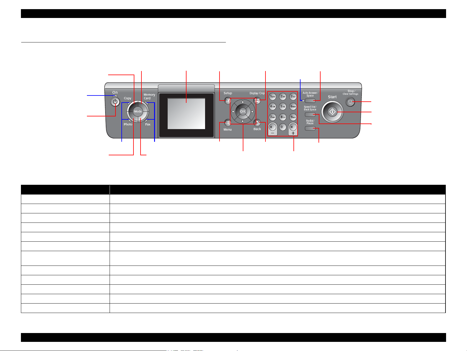
1.6 Control Panel
1.6.1 Operation Buttons & LEDs
Figure 1-5. Control Panel
Table 1-17. Button Functions
Button Function
Power Turns the power ON/OFF.
Copy Goes to the stand alone Copy mode.
Memory Card Goes to the memory card direct print mode.
Photo Goes to the special mode that provides Reprint/Restore Photos function.
Fax Goes to the mode that provides fax transmission.
Setup Goes to the Setup mode that provides maintenance menu (head cleaning, head alignment, etc.) and various setting menu.
Display/Crop
Menu Goes to the print setting menu screen.
Cross Key (Up/Down/Left/Right) Selects a menu item or a setting value.
OK Accepts the changed settings
Back Cancels the previous operation.
Start Starts printing.
• Goes to the zoom setting screen for the selected image.
• Changes the image preview layout on the LCD.
Continued on next page
PRODUCT DESCRIPTION Control Panel 21
Page 22

EPSON Stylus CX9300F/CX9400Fax/DX9400F Revision A
Table 1-17. Button Functions
Button Function
• Stops operation and displays the menu screen.
Stop/Clear Settings
Ten keys Enters alphameric characters.
Auto Answer/Space Turns ON/OFF the auto answer settings.
Speed Dial/Back Space Goes to the call-up screen for speed dials.
Redial/Pause Calls at the last dialed number.
LED Function
Power (Green)
Mode LED
Auto Answer • Lights when Auto answer is on.
Card Access*2 (Green)
Note *1 : In the Setup mode, the mode LED corresponding to the previous mode lights.
*2 : The Card Access LED is provided near the memory card slot.
• Stops printing and ejects paper.
• Returns the print settings in the current mode to their defaults and displays the Top screen.
(Returns to the previous screen during printing maintaining the current settings)
Table 1-18. LED Functions
• Flashes while powering ON/OFF.
• Flashes during some sequence is in progress.
• Flashes when a fatal error occurs.
• Lights when the status is other than above.
• All the mode LEDs are off while powering ON.
• The current mode LED lights while powering OFF.
• All the mode LEDs flash when a fatal error occurs.
• The current mode LED lights when in stand-by or in setting operation using the control panel.
• The current mode LED lights during some sequence is in progress.*
• The memory card mode LED lights during slide show is being displayed.
• The current mode LED lights during screen saver is being displayed.*
• All the mode LEDs light sequentially at one minute intervals when in power saver mode.
• Lights when a memory card is inserted.
• Flashes when a memory card is being identified or accessed.
1
1
PRODUCT DESCRIPTION Control Panel 22
Page 23
EPSON Stylus CX9300F/CX9400Fax/DX9400F Revision A
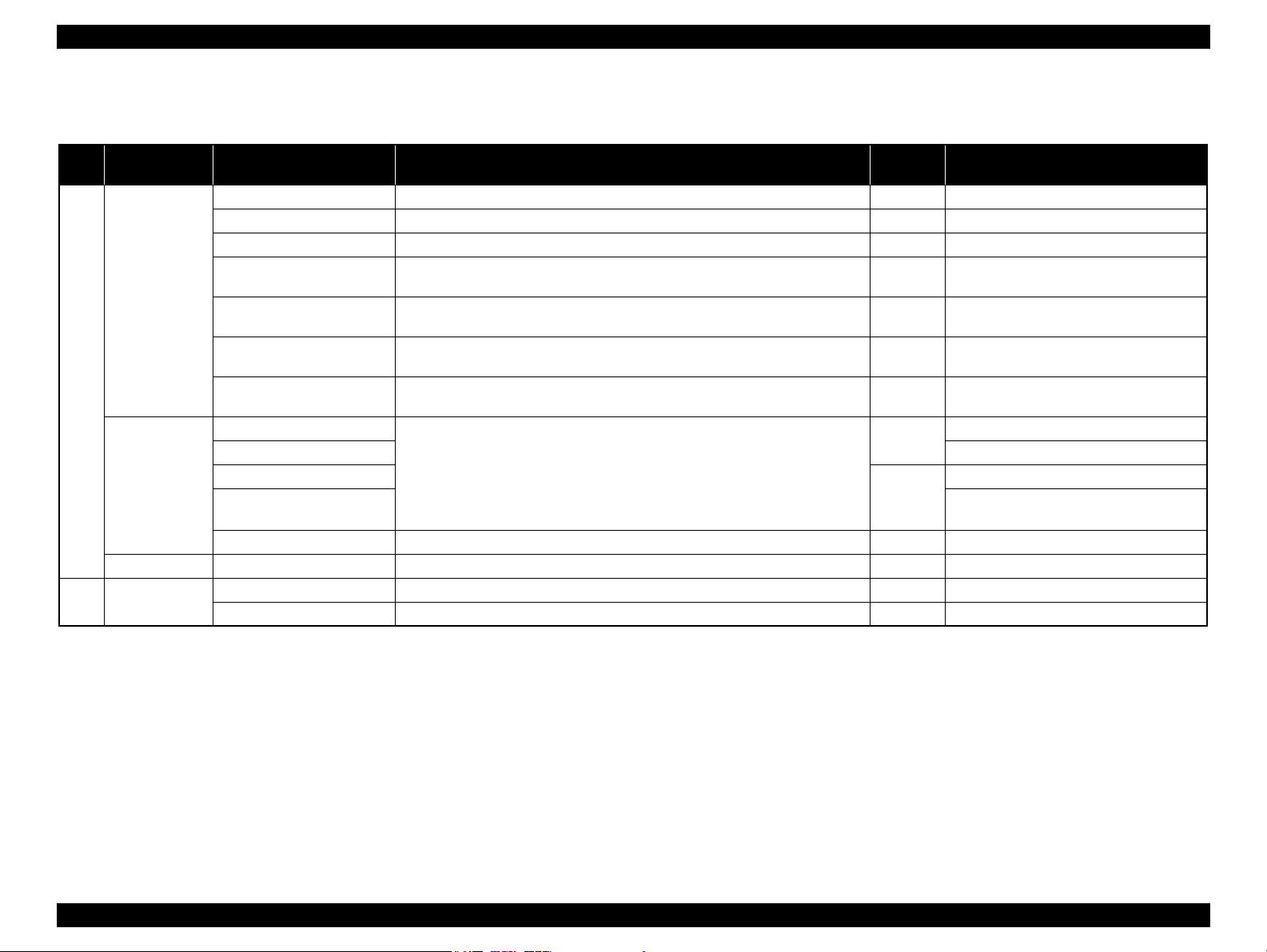
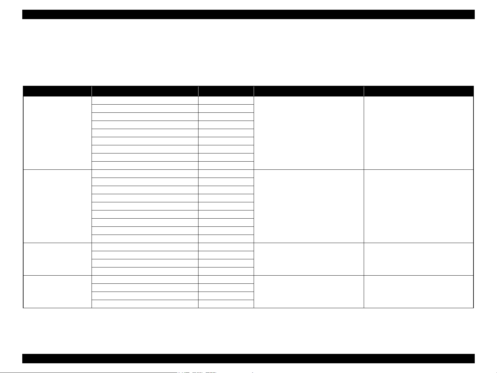
1.6.2 Control Panel Functions in Each Mode
1.6.2.1 Control Panel Functions
The table below shows the print setting menu items for each mode and their defaults, and when the settings are saved or returned to their defaults. Explanations on detailed control
panel functions of the CX9300F/CX9400Fax/DX9400F are omitted here, because the LCD displays the detailed instruction.
Table 1-19. Timing of Saving or Initializing Control Panel Settings
Mode Print Setting Default Value Saving Timing Initializing Timing*
Copy
Memory Card
Photo
FAX
Copy Type Color
Layout With Border
Number of copies 1
Zoom Actual
Paper Type Plain Paper
Paper Size A4, Letter (for EAI)
Quality Standard
Density ±0
Expansion Standard
Paper Type Prem. Glossy
Paper Size 4x6 inch
Layout Borderless
Quality Standard
Expansion Standard
Date None
Bidirectional On
Select (Print Index Sheet setting) All Photos
Information (Print Index Sheet setting) (EAI only) File Name
Paper Type Prem. Glossy
Paper Size 4x6 inch
Layout Borderless
Expansion Standard
Resolution Standard
Contrast ±0
Fax Delay Off
Fax Mode Sending
When the Start button is pressed When the Stop/Clear button is pressed
When the Start button is pressed When the Stop/Clear button is pressed
When the Start button is pressed When the Stop/Clear button is pressed
When the Start button is pressed When the Stop/Clear button is pressed
PRODUCT DESCRIPTION Control Panel 23
Page 24
EPSON Stylus CX9300F/CX9400Fax/DX9400F Revision A
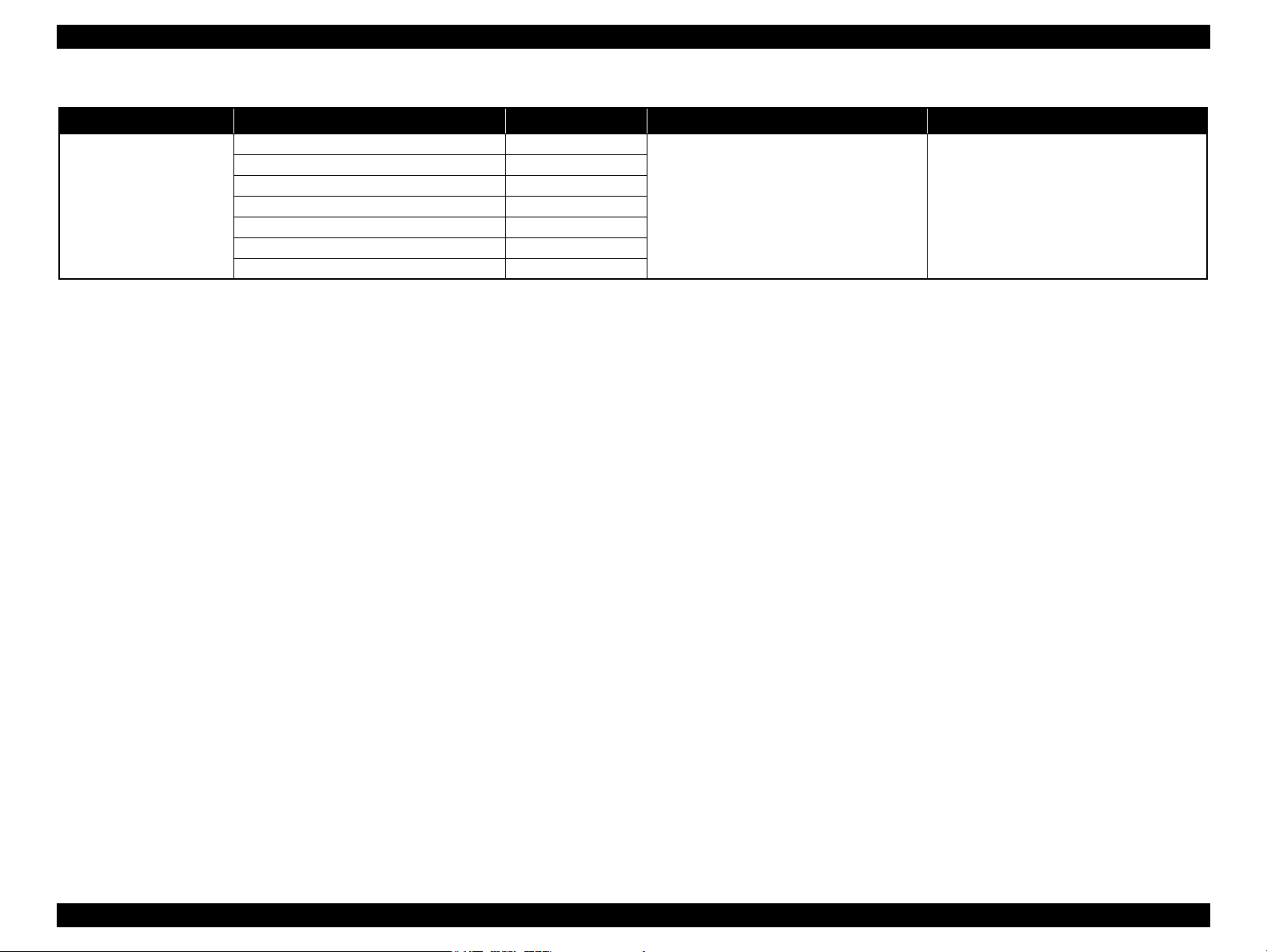
Table 1-19. Timing of Saving or Initializing Control Panel Settings
Mode Print Setting Default Value Saving Timing Initializing Timing*
Camera Direct
Note * : All the settings except “LCD Brightness” of Setup menu return to their defaults when the “Restore Default Settings” of the Setup menu is executed with the OK button.
Paper type Prem. Glossy
Paper size 4x6 inch
Layout Borderless
Quality Standard
Expansion Standard
Date None
Bidirectional On
When the settings are made in the PictBridge Setup
of the Setup menu.
When the Stop/Clear button is pressed while
making the settings.
1.6.2.2 Control Panel Power Saver Mode
If no operation is made on the control panel for approximately 13 minutes, both the CX9300F/CX9400Fax/DX9400F automatically enter control panel power saver mode. The
details of control panel power save mode are shown below.
Conditions for not entering the control panel power save mode
• The printer or scanner is in operation
• During printing or scanning from PC
• Camera direct is in operation
• Slide show is being displayed
• An error is being displayed
• Mechanical adjustment is being made in setup mode
• Firmware is being updated
Conditions recovering from the control panel power save mode
• Any button other than the power button is pressed (when the power button is pressed, the power is turned OFF)
• A memory card or a camera direct device is connected
• Operation from PC (printing / scanning / maintenance)
NOTE: See “ 1.7.3.4 Operating Specifications during Connecting DSC ( p. 32 ) ” for information on the panel operation during connecting a camera to the EXT.IF.
PRODUCT DESCRIPTION Control Panel 24
Page 25
EPSON Stylus CX9300F/CX9400Fax/DX9400F Revision A
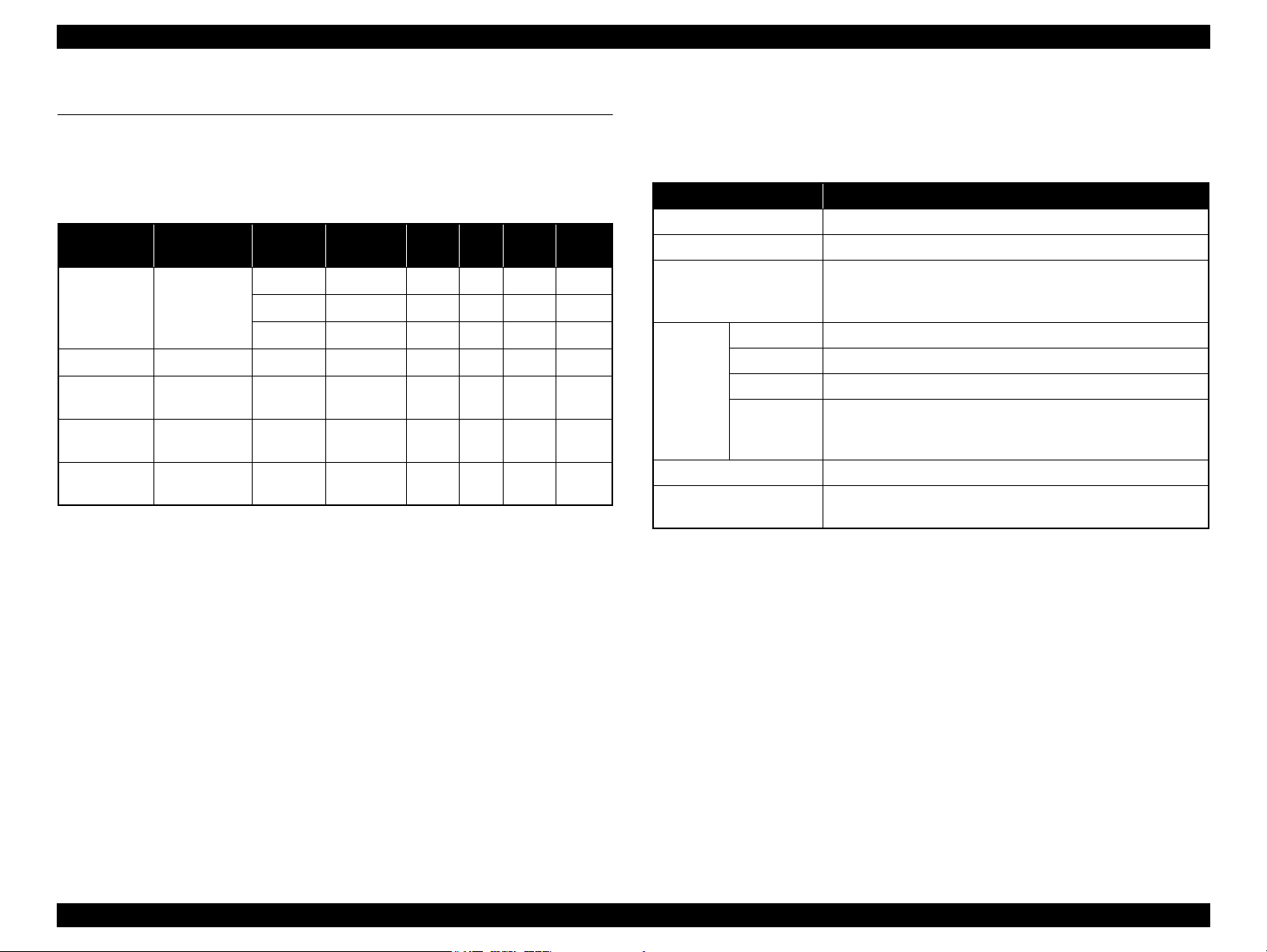
1.7 Specification for Each Function
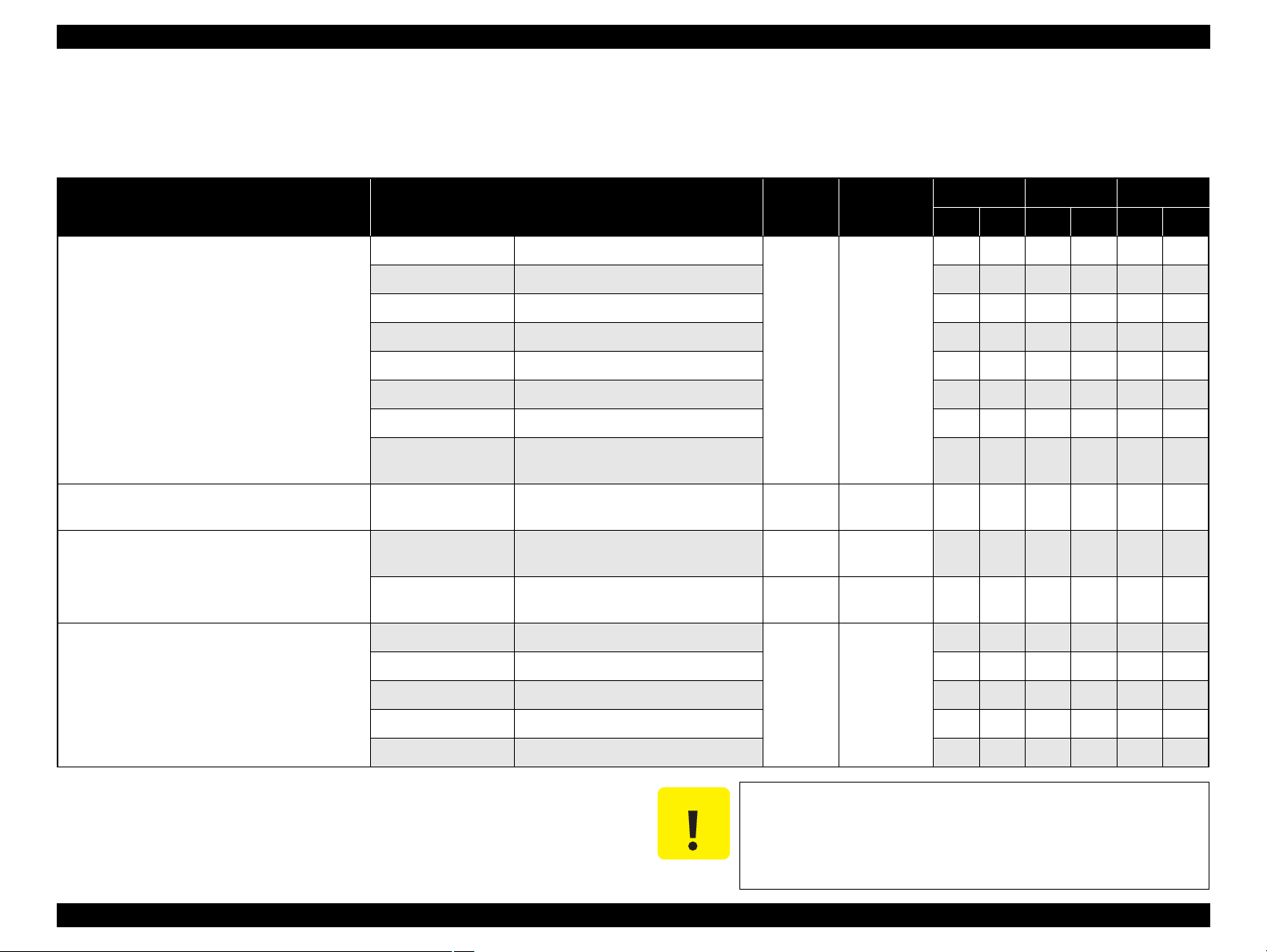
1.7.1 Stand-alone Copy Function
1.7.1.1 Supported Paper and Copy Mode
Table 1-20. Supported Paper and Copy Mode
*1
*1
*1
*1
*1
Print
Quality
Draft
Standard
Best
Standard
Standard
Standard
Standard
Resolution
360x120 Eco ON OFF
360x360 VSD1 ON OFF
720x720 VSD3 ON ON
1440x720 VSD3 ON ON
1440x720 VSD3 ON ON
1440x720 VSD3 ON ON
1440x720 VSD3 ON ON
Paper Type
Plain paper A4*1, Letter
Matte paper A4*1, Letter
Photo Paper
Prem. Glossy
Ultra Glossy
Note *1 : The model for Latin supports both the letter and A4 sizes. The model for North
*2 : Borderless printing of 5x7 size is not supported for EAI.
Note : In the case of copy using ADF, only the plain paper is available.
A4*1, Letter
A4*1, Letter
A4
America supports letter size only, and the other destination models support A4 size
only.
1
Size*
4x6, 5x7,
4x6, 5x7,
4x6, 5x7,
*1
, Letter
Dot
Size
Bi-d
Micro
Weave
Border-
OK*
less
NA
NA
NA
OK
OK
OK
1.7.1.2 Stand-alone Copy Menu
The stand-alone copy mode menu for the CX9300F/CX9400Fax/DX9400F (settable
items) are shown in the following tables.
Table 1-21. Copy Menus
Menu Function
Number of copies Sets the number of copies within the range of 1 to 99.
Copy type Selects either color or monochrome.
Selects from the following two layouts:
Layout
Paper type Selects paper type from the options shown in Table 1-20.
Paper size Selects paper size from the options shown in Table 1-20.
2
Print
setting
Density Selects from the nine density levels of -4 to +/-0 to +4.
Expansion
(for borderless print)
Quality Selects print quality from the options shown in Table 1-20.
Zoom
• With Border (normal layout with 3mm margins)
• Borderless (no margins)
Selects Actual or Auto Fit Page.
Or reduction/enlargement ratio can be specified within the range
of 25% to 400%.
Selects the margins level (margins bleed off the edges of paper)
from the Standard (100%), Mid. (50%) or Min. (0%).*
PRODUCT DESCRIPTION Specification for Each Function 25
Page 26
EPSON Stylus CX9300F/CX9400Fax/DX9400F Revision A
a
a
a
a
Scan / Print direction
A
A
B
B
C
C
D
D
E
E
F
F
Readable Length
Paper Length
Paper
Width
Paper Length
Readable
Width
Readable Length
OTM
OTM
OLM
LM
LM
RM
RM
TM
BM
TM
OLM
Home position
Home position
BM
1.7.1.3 Relation Between Original and Copy
The scanning start position is located on the front right of the scan bed. The relations
between the original placed face down and its copy are as follows.
Figure 1-6. Relation Between Original and Copy (Borderless/With Borders)
Original Document
A Scan bed ---
B Scan area “ 1-10 Scanning Range ” (p.17)
C Original (face down) ---
OTM Top margin (out of scan range) “ 1-10 Scanning Range ” (p.17)
OLM Left margin (out of scan range) “ 1-10 Scanning Range ” (p.17)
Copied Document
D Copied paper ---
EPrint area “ 1-7 Printing Area (Margins) ” (p.16)
FCopy ---
LM, RM Left margin, Right margin* “ 1-7 Printing Area (Margins) ” (p.16)
TM, BM Top margin, Bottom margin*
PRODUCT DESCRIPTION Specification for Each Function 26
1.7.1.4 Copy Speed
Copy Conditions
(eMemo2, A4 size)
Draft 360 x 120
Default 360 x 360
Table 1-22. Copy Speed
Monochrome copy
Color copy
Monochrome copy
Color copy
Copy Speed
T.B.D. cpm
T.B.D. cpm
Page 27
EPSON Stylus CX9300F/CX9400Fax/DX9400F Revision A
C H E C K
P O I N T
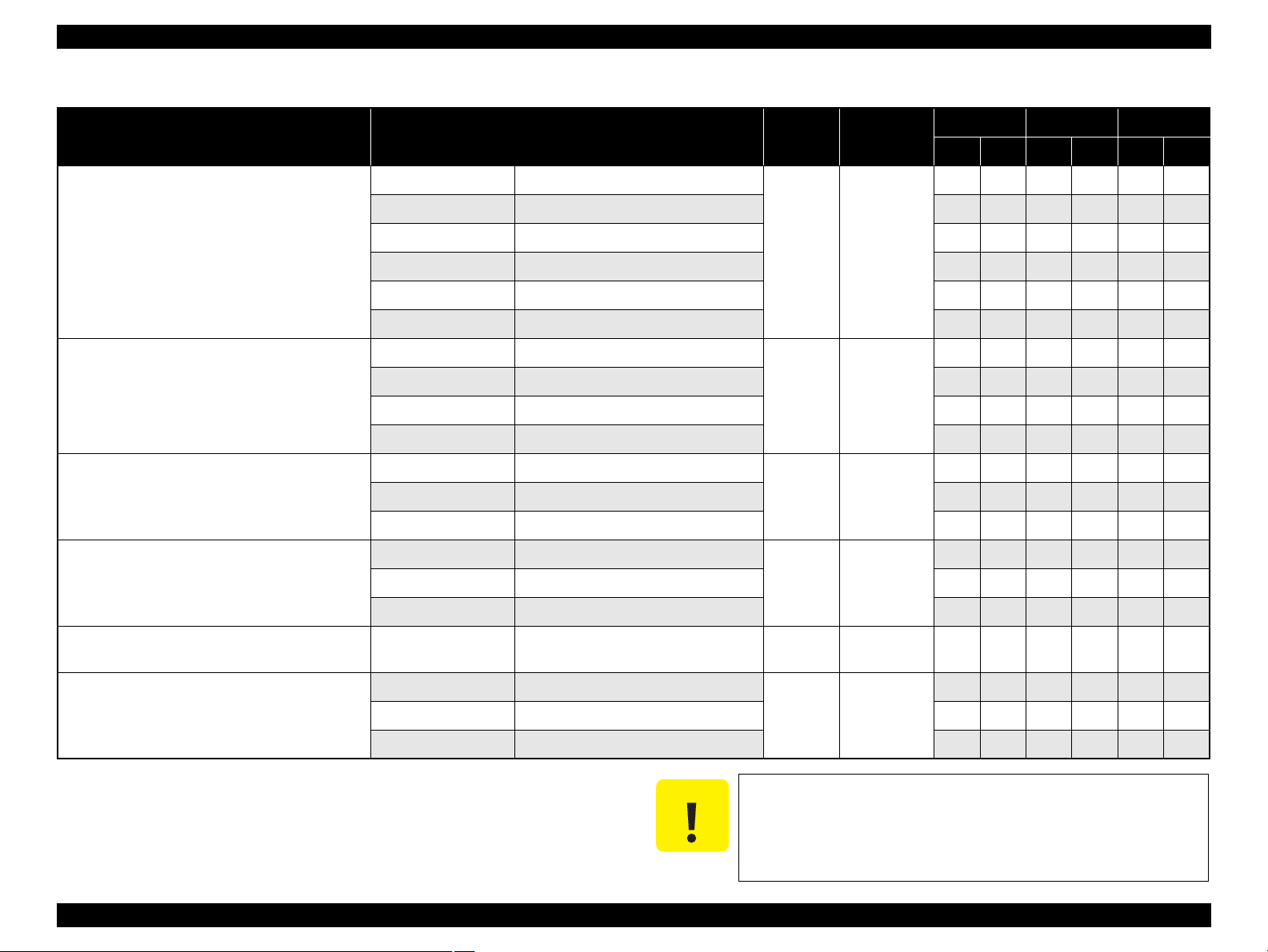
1.7.2 Memory Card Direct Print Function
1.7.2.1 Supported Paper and Print Mode
Table 1-23. Supported Paper Type & Print Mode
*1
*1
*1
*1
Print
Quality
Standard
Best
Standard
Standard
Standard
Resolution
360x360 VSD1 ON OFF
720x720 VSD3 ON ON
1440x720 VSD3 ON ON
1440x720 VSD3 ON ON
1440x720 VSD3 ON ON
1440x720 VSD3 ON ON
Paper Type Size
Plain Paper A4, Letter
Matte Paper A4, Letter*1Standard
Photo Paper
Prem. Glossy
Ultra Glossy
Note *1 : Letter size is supported for EAI only.
*2 : The Photo Paper 5x7 size and Prem. Glossy 16:9 wide are not supported for EAI.
4x6, 5x7*2,
A4, Letter
4x6, 5x7,
16:9 wide*2,
A4, Letter
4x6, 5x7,
A4, Letter
Dot
Size
Bi-d
Micro
Weave
Border-
less
NA
NA
OK
OK
OK
OK
1.7.2.2 Supported File Type and Media Type
The followings describe the file system, media format, and file type supported by the
memory card direct function.
Table 1-24. Supported File System, Types and Media Format
Item Specification
DCF Version 1.0 or 2.0 *1 compliant. Other than those does
File system
Media format Memory card
JPEG (*.JPG)
TIFF (*.TIF)
File type
Note *1: Refer to the Camera File System Standard; “DCF Version 2.0, JEIDA-CP-3461” for
*2 : Available only when the memory card supports FAT32.
Camera
definition file
(*.MRK)
more details.
The printer does not detect any files stored under the following
directories or their sub-directories.
• Directories containing system properties or hidden properties.
• “RECYCLED” (Windows directory for deleted files)
• “PREVIEW” (directories of CASIO DSC for thumbnail images)
• “SCENE” (directories of CASIO DSC for its Best Shot function)
• “MSSONY” (directories of SONY DSC for e-mail images, voice memos,
movies, or non-compressed images)
• “DCIM\ALBUM\IMAGE” (directories of CASIO DSC for its album
function)
not ensure proper operation. File systems available with the
card reader function are restricted by the host’s specification.
• DCF Version 1.0 or 2.0 compliant
• DOS FAT format (FAT12/FAT16/FAT32 *2) with single
partition (basic partitioned)
Image files conform to Exif Version 2.21. (Exif version 1.0/
2.0/2.1/2.2/2.21 are supported)
Camera definition files used for DPOF mode.
“\MISC\AUTOPRINT.MRK” file is valid.
1.7.2.3 Automatic Detection of Images in Memory Card
When a memory card is inserted in the card slot on the printer, or when a memory card
is detected at power-on, the printer automatically searches for all images stored in the
card. When the card is removed, the printer erases the information on the all detected
files.
PRODUCT DESCRIPTION Specification for Each Function 27
Page 28
EPSON Stylus CX9300F/CX9400Fax/DX9400F Revision A
1.7.2.4 Specifications for Handling Image Data
Table 1-25. Specifications for Handling Image Data
Item Specification Remarks
Image size (pixel)
Maximum number
of images
Maximum number
of copies
Valid date and time
Thumbnail image
data
File sorting
• Horizontal: 80 ≤ X ≤ 9200
• Vertical: 80 ≤ Y ≤ 9200
Up to 999 images When a memory card stores 1,000
or more images, the first 999
images are detected and become
valid in the printer. The detecting
order varies depending on the
folder configuration in the card, so
which images are included in the
first 999 cannot be defined.
However, images specified by
camera definition files can be
selected to be printed even when
the total number of images has
exceeded 999. Up to 999 camera
defined image files can be
specified.
99 copies for each image.
Up to 999 sheets in total.
01/01/1980 00:00:00 to
12/31/2099 23:59:59
Supports DCF Ver.1.0 or 2.0compatible data (Exif format,
160x120 pixels)
The printer sorts image files in
ascending ASCII order based on
their full-pathnames such as
“\DCIM\100EPSON\EPSN0000.
JPG”, and assigns a number to
each of them.
Thumbnail images are used for the
Print Index Sheet function.
• The image number assigned by
the printer may be different from
that assigned by the camera.
• If two or more files have the
same full pathname, the sorting
function may not operate
properly. (existence of the same
full-pathname is not allowed
under DOS)
---
---
---
Table 1-25. Specifications for Handling Image Data
Item Specification Remarks
The printer acquires date and time
information included in image
files in the order of precedence
shown below.
1. Shooting date and time
information in digital camera
standard format (Exif)
2. Digitized date and time
Acquisition of date
and time
information
information in digital camera
standard format (Exif)
3. Date and time information in
digital camera standard format
(Exif)
4. Date and time information
applied on DOS-compliant file
system.
5. Fixed date and time
information (01/01/1980,
00:00:00)
Date and time information included
in an image file is not always the
shooting date and time. It changes
each time the image is edited and
restored. The printer acquires the
latest date and time information.
PRODUCT DESCRIPTION Specification for Each Function 28
Page 29
EPSON Stylus CX9300F/CX9400Fax/DX9400F Revision A
1.7.2.5 Memory Card Direct Print Menu
The LCD-equipped CX9300F/CX9400Fax/DX9400F provide the following menus in
the memory card mode.
Table 1-26. Memory Card Mode Menu
Menu Item Function
View and Print
1,2
Photos*
Print All
1,2
Photos*
Print by Date*
Print Index Sheet
Slide Show*
Note *1: 0 to 99 copies can be specified for each of the images. Up to 999 copies in total.
*2 : The images are listed in ASCII descending order.
*3 : While performing the slide show, displaying number of copies, printing from an
external device or from a computer cannot be made.
Prints the selected images.
Prints all images in a memory card. Specified number of copies is applied
to the all images (the default is 1 copy). Specifying it for each of the
images independently also can be made in the preview screen.
The date of the images are listed in the descending order with the number
of images by date. Selecting date from the list selects the images that has
1
the selected date information. Specified number of copies is applied to the
selected images (the default is 1 copy). Specifying it for each of the
images independently also can be made in the preview screen.
Print Index Sheet
Prints an index sheet that prints images in a memory card in thumbnailed
form. The number of images to be included in the sheet can be selected
from the following four options.
“All image” (default), “Latest 30”, “Latest 60”, “Latest 90”*
Make Prints from Index Sheet
Scans the index sheet, and prints images according to markings written on
the sheet.
Starts a slide show on the LCD. Images in a memory card is displayed one
3
by one in the order sorted by the printer. Printing one of the images can be
made from the paused screen.
2
1.7.2.6 Makes Prints from Index Sheet Function
Print settings
Table 1-27. Print Settings
Item Print Index Sheet Makes Prints from Index Sheet
Number of copies ---
Paper Type Plain paper
Paper Size A4
Layout ---
Quality Standard Standard
Expansion ---
Date
YYYY.MM.DD
(2007.09.21)*
1
Bi-directional On On
Print Index Sheet
Setting-Select
According to the setting
made by the control panel.
Note *1: EAI model: MMM.DD.YYYY (Sep. 21.2007)
Rules on reading Index Sheet markings
The user can specify images to be printed and their print settings shown in Table
1-27 by putting marking on the Index Sheet. The printer reads the markings
according to the following rules.
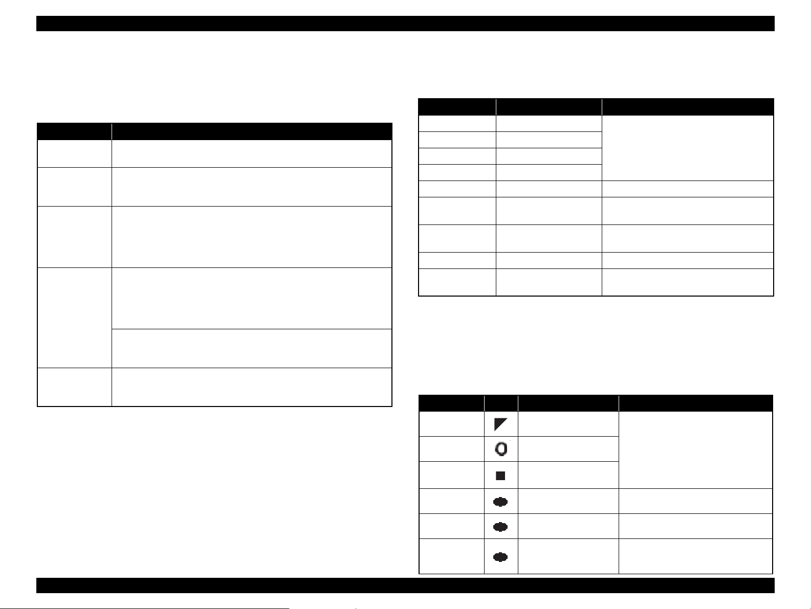
Table 1-28. Rules on Reading Markings
Item
Left edge
(one each)
Right edge
(one each)
Block code
(36 pcs.)
Image selection
(30 pcs. x 3)
Paper type/size
(4 pcs.)
Layout (2 pcs.)
Mark
Description Remarks
Reference position for
reading markings.
Reference position for
reading markings.
Sheet information
(memory card, page)
Selects the image to be
printed.
Selects the paper type/size. An error occurs if two or more markings are
Selects the layout. An error occurs if two or more markings are
According to the marking on the index
sheet.
According to the setting made by the control
panel.
According to the setting made by the control
panel. YYYY.MM.DD (2007.09.21)*
---
An error occurs if these markings cannot be
read due to ink stain or any other cause.
An error occurs if no image selection
marking is read.
read for one image.
read for one image. If no marking is read,
borderless layout is applied.
1
PRODUCT DESCRIPTION Specification for Each Function 29
Page 30

EPSON Stylus CX9300F/CX9400Fax/DX9400F Revision A
<OK example> <NG example>
(not enough)
(too much)
Trimmed areas
Photo frame
(print area)
• When an image is aligned vertically with the photo frame.
• When an image is aligned horizontally with the photo frame.
Photo frame
(print area)
Trimmed
areas
Table 1-28. Rules on Reading Markings
Item
Date Prints the date information. When this marking is read, the date is
Note: • About 50% or more range of the mark area must be marked out to be read by the
printer.
• For running out and excessive marking out, the two white/black search patterns shown
above are superimposed on the mark, and judgement is made according to this
matching ratio.
• The judgement criteria is as follows;
black matching: 80% or more, white matching: 50% or more.
• The figure below shows the judgement example according to the rules described
above.
Mark
Description Remarks
printed on the image.
Index Sheet errors
Table 1-29. Index Sheet Error List
Error Name Description
Index sheet scan error
(incorrect sheet setting)
Index sheet scan error
(incorrect image selection
marking)*
Index sheet scan error
(incorrect paper selection
marking)
Index sheet scan error
(unmatch between memory
card and sheet)
The Index Sheet is not properly placed on the document glass.
Image selection markings are not correct.
Paper selection markings are not correct.
The memory card may have been changed or some images
may have been added or deleted after the Index Sheet is
printed.
1.7.2.7 Print Layout
The memory card direct print function supports two print layouts for printing images;
Borderless, and With Border. The Borderless layout is not allowed for some type of
paper (refer to
the print area and margins of “Borderless” and “With Border” layouts.
Trimming Function
A trimming function is provided as a means of coordinating an image with the
types of photo frames handled by the printer. This function is always activated so
that the image fits within the photo frames.
This function is described briefly below.
The printed photo frame and an image to be printed are matched in length along
one side and the image is resized along the perpendicular side to fit the frame on
that side. Any part of the image that does not fit within the photo frame is trimmed
away (not printed).
Table 1-23). And see “ 1.2.5 Printing Area ” (p.16) for information on
Figure 1-7. Trimming Function
PRODUCT DESCRIPTION Specification for Each Function 30
Page 31

EPSON Stylus CX9300F/CX9400Fax/DX9400F Revision A
<Borderless>
<With Border>
Paper top edge
Rules on Numbering and Rotating Images
The numbers shown in the figure below indicate the photo frame numbers used for
the print layout. Horizontally oriented images are printed as shown by the
numbers. Vertically oriented images, which has more pixels vertically than
horizontally, the vertical photo data is allocated instead, and the number shown in
the figure below is then rotated 90 degrees before being printed. In Index printing
mode, the numbers are printed as they are shown below, regardless of the shape of
the photo data.
However, when the photo data has an equal number of pixels vertically and
horizontally the photos are printed without rotation, regardless of the layout.
NOTE: The vertical photo data refers to when the photo data file itself is set for a
vertical (portrait) orientation. Photo data is defined as the vertical photo
data if it is taken by a digital camera with a portrait position detecting
function.)
Figure 1-8. Rules on Numbering and Rotating Images
1.7.3 Camera Direct Print Function
(USB Direct Print/PictBridge)
Printing operations (selecting images to be printed, making print settings, starting/
canceling printing, and monitoring print process) can be carried out from a directly
connected DSC (Digital Still Camera) that conforms to the standard described below.
1.7.3.1 Available DSC
Table 1-30. Available DSC
USB Direct Print PictBridge
DSCs conform to USB Direct Print
Protocol Revision 1.0.
1.7.3.2 Print Settings Available from DSC
The following print settings can be made from the DSC. However, depending on the
DSC, some of the settings may not be available.
Table 1-31. Print Settings Available from DSC
Item USB Direct Print PictBridge
How to specify images Single Sheet / DPOF specified Single Sheet / Multiple Sheet /
Paper type Plain Paper/ Glossy Photo / Prem.
Glossy / Matte
Paper size 4x6, 5x7, Letter (EAI model only), A4
Layout Borderless
With Borders
(2-up, 4-up, 8-up are available
when specified by DPOF)
Date On / Off
Quality Not available
Auto Correct Not available
Fit to Frame Available only for a single sheet Available
Print Image Framer Yes / No Not available
Control of printer The following operations are available; Getting the printer status, starting
a print job or canceling it immediately or after printing the current page is
finished. (In the case of the USB Direct Print, resetting the printer is also
available.)
DSCs conform to CIPA DC-001-2003 Digital Photo
Solutions for Imaging Devices (DPS version 1.0) or
the Rev. 2.0.
DPOF specified
Plain Paper/ Prem. Glossy
Borderless
With Borders
PRODUCT DESCRIPTION Specification for Each Function 31
Page 32

EPSON Stylus CX9300F/CX9400Fax/DX9400F Revision A
C H E C K
P O I N T
1.7.3.3 General Operation Procedure
Before connecting the DSC, check that the printer is in the
following status.
• No print job from a computer is processed or performed.
• Direct print from a memory card is not processed or performed.
• Stand alone copy using the scanner function is not operating.
• No paper out error or ink out error is occurring.
The DSC direct print procedure differs depending on the DSC specifications. The
following explains common procedure.
1. Setting on the printer
Before connecting a DSC with a USB cable, make the print settings such as paper
type/size, layout setting on the printer. This may not be required for some DSCs.
2. Setting on the DSC
Make the following settings on the DSC before connecting it to the printer. Some
DSCs may require to first connect to the printer for making the settings.
• When printing multiple images, specify images and number of copies using
the DPOF and Multiple Sheet* menus. The menus may not be available on
some DSCs.
Note*: The Multiple Sheet setting is available when using PictBridge.
• When printing a single image
<USB Direct Print>
Use the Single Sheet menu to specify an image and the number of copies.
The menu may not be available on some DSCs.
<PictBridge>
Specify an image and the number of copies. Specifying the number of
copies may not be available on some DSCs.
• Select the paper type/size, layout, and make the Fit to Frame setting if
necessary. These settings may not be available on some DSCs.
1.7.3.4 Operating Specifications during Connecting DSC
Table 1-32. Operations during Connecting DSC
Operation Specifications
Connecting
DSC
(print start)
Canceling
printing
After printing
is completed
Exclusion
control
When a DSC is connected as described in “ 1.7.3.3 General Operation
Procedure ( p. 32 ) ” Step 3-1, CX9300F/CX9400Fax/DX9400F displays USB
Direct Print or PictBridge logo on the LCD.
A print job can be canceled from the DSC.
The [Stop/Clear setting] button also cancels the print job.
When performing memory card direct print after printing from a DSC, the
USB cable connecting the DSC must be disconnected from the printer in
advance.
Print settings made on both the DSC and the printer can become impossible
settings for the printer due to unsupported combination of paper type, paper
size and layout. In such case, the print settings are automatically changed as
follows.
USB Direct Print
The selected paper type is maintained, and the paper size and layout
settings are changed to the default for the selected paper type.
PictBridge
The settings made on the DSC are maintained. Any print setting items that
are not specified by the DSC are changed in accordance with the DSC
settings. When the paper type is changed, changed to Prem. Glossy, when
the paper size is changed, changed to 4x6 size. And when the layout is
changed, changed to Borderless layout.
3. Starting to print
When the print settings on both the printer and the DSC is completed, follow the
procedure below to start printing.
1. Connect the printer and the DSC with a USB cable. Using a USB cable
included in the DSC package is recommended.
2. Operate the DSC to start printing.
3. Printing is carried out according to the settings made on the DSC. When some
print settings have not been made on the DSC, the corresponding settings
made on the printer are applied.
PRODUCT DESCRIPTION Specification for Each Function 32
Page 33

EPSON Stylus CX9300F/CX9400Fax/DX9400F Revision A
1.7.3.5 EXT.I/F (USB Host) Specifications for Connecting DSC
Table 1-33. Operations when USB Cable is Connected/Disconnected
Printer status Connecting Disconnecting
Standby When the printer detects a DSC
connected, it goes into the camera
direct mode. If the printer failed to
recognize the DSC normally, the
printer displays a camera direct error.
An error is
occurring
Panel power
save mode
The printer does not go into the
camera direct mode except when the
error is memory card-related error,
Index Sheet error, or Ink low error.
Same as when the printer is in
standby mode.
When the DSC is disconnected after
it is normally recognized by the
printer, the printer returns to the
standby mode.
When a camera direct error has
occurred, the printer recovers from
the error and returns to the previous
state (the state before the camera is
connected). If the error occurs for the
camera connected before the printer
is turned on, the printer returns to the
initial state after the power-on.
The printer does not recover from the
power save mode. When any button
except the Power button is pressed,
the printer returns to the camera
direct mode. If the printer detect no
camera at this time, it returns to the
previous state (the state before the
camera is connected)
1.7.4 Reprint/Restore Photos Function
CX9300F/CX9400Fax/DX9400F offers the photo copy function. This function allows
the user to copy their silver halide film-based pictures. The printer scans the pictures
automatically detecting them as silver halide film-based picture, and makes a copy of
them.
1.7.4.1 Supported Paper Type and Print Mode
Table 1-35. Paper Type and Print Mode
Paper Type Size Quality Resolution
Letter
Letter
*1
Standard
Standard
*1
Standard
*1
Standard
*1
1440x720 VSD3 ON ON
1440x720 VSD3 ON ON
1440x720 VSD3 ON ON
1440x720 VSD3 ON ON
Matte paper A4, Letter
Photo Paper
Prem. Glossy
Ultra Glossy
Note *1 : Letter size is supported for EAI only.
*2 : The Photo Paper 5x7 size is not supported for EAI.
4x6, 5x7*2,
A4, Letter
4x6, 5x7, A4,
4x6, 5x7, A4,
1.7.4.2 Reprint/Restore Photos Menu
Dot
size
Bi-d
Micro
Weave
Borde
rless
OK
OK
OK
OK
Table 1-34. Handling Print Job Requirement from PC when Connecting DSC
Requirement
from PC
Print job Returns “Busy” to the PC.
Scan job Returns “Busy” to the PC.
Read memory
card
Write memory
card
Maintenance
Allows the access. Allows the access.
Not allows the access. Notifies the
PC that the operation is not available.
Returns “Busy” to the PC.
EXT.IF (USB Host) DSC Connecting Status
Normally Connected Camera Direct Error is Occurring
Cancels the error state and performs
the job.
Cancels the error state and performs
the job.
Allows the access.
Cancels the error and carries out the
required task.
Items Function
Number of copies Sets the number of copies within the range of 1 to 99.
Paper type Selects paper type from the options shown in Table 1-35.
Paper size Selects paper size from the options shown in Table 1-35.
Layout
Quality Fixed to “Standard“.
Expansion
Table 1-36. Reprint/Restore Photos Menu
Selects print layout from the following three options:
• Standard (normal layout with 3mm margins)
• Borderless (no margins)
Selects the margins level (margins bleed off the edges of paper)
from the Standard (100%), Mid. (50%) or Min. (0%).
PRODUCT DESCRIPTION Specification for Each Function 33
Page 34

EPSON Stylus CX9300F/CX9400Fax/DX9400F Revision A
Picture (2)
Picture (1)
5 mm or more
5mm
5mm
Home position
Scanning Direction
Document
Glass
ROM
version
Q-PIT version
32 dots
360 dpi VSD1 dot
0.2117mm (1/120inch)
Cyan Magenta Yellow Black
Note : The numbers shown in the figure are nozzle numbers. The numbers and the color names
are not printed on an actual nozzle check pattern.
1.7.4.3 How to Place Silver Halide Pictures
The following explains how to place silver halide film-based pictures on the document
glass of the printer.
Available picture size: 30x40 mm to 127x178mm (5”x7”)
Lay the pictures on the glass face down.
The number of pictures available at one time is as follows:
• 4x6 or smaller: up to 2 pictures
• 5x7: up to 1 picture
The following spaces are needed:
• 5 mm or more space from the right and front edges of the document glass.
• 5 mm or more space between pictures.
The pictures must not be tilted.
1.7.5 Setup Mode
CX9300F/CX9400Fax/DX9400F go into the setup mode when the Setup button is
pressed. Various maintenance functions and configuration settings can be made in this
mode.
1.7.5.1 Ink Levels
The current ink levels of each of the cartridges are displayed in bar chart by the rules
described below. After displaying the ink levels, the next operation can be selected
from the following two options; “End the ink levels display” or “Change Ink
Cartridge”.
• The bar chart is displayed in the order of cyan, magenta, yellow, and black from the left.
• When initial filling is completed, or after replacing the cartridge, the ink level becomes
100% (full).
• The ink level is indicated in increment of 1%. Lower than 1% is rounded down.
• When the ink level becomes lower than 10%, “!” icon appears to notify the user of the ink
low status.
1.7.5.2 Nozzle Check
A nozzle check pattern to check the Printhead nozzles status is printed. A head cleaning can be run if necessary.
1
11
21
31
41
51
61
71
81
1
10
11
20
21
30
31
40
41
50
51
60
61
70
71
80
81
90
1
10
11
20
21
30
31
40
41
50
51
60
61
70
71
80
81
90
1
10
11
20
21
30
31
40
41
50
51
60
61
70
71
80
81
90
10
20
30
40
50
60
70
80
90
Figure 1-9. Laying Silver Halide Pictures
PRODUCT DESCRIPTION Specification for Each Function 34
Figure 1-10. Nozzle Check Pattern
Page 35

EPSON Stylus CX9300F/CX9400Fax/DX9400F Revision A
C A U T I O N
C H E C K
P O I N T
1.7.5.3 Head Cleaning
Runs a printhead cleaning. The cleaning cannot be made when low ink level is
detected. In such case, an ink low error is displayed instead of running the cleaning.
1.7.5.4 Change Ink Cartridge
CX9300F/CX9400Fax/DX9400F run the ink cartridge replacement sequence when
“Change Ink Cartridge” option is selected in the Ink Levels display menu. And when
an ink low or out error occurs, the user can run the replacement sequence by following
the instructions displayed on the LCD.
1.7.5.5 LCD Brightness
This allows the user to adjust the brightness of the LCD.
The settable range is -10 (minimum) to +10 (maximum).
1.7.5.6 Display Format
The layout to preview images on the LCD can be selected from the following options;
1-up with Info, 1-up without Info, 16-up. This setting is applied to preview images
using the following functions of the memory card mode.
• Print All Photos
• View and Print Photos
• Print by Date
• Slide Show
1.7.5.7 PictBridge Setup
The print settings to be used for the camera direct print (USB Direct Print/PictBridge)
can be specified. When print settings (paper type, paper size, layout, quality, auto
correct) are specified from the DSC, the DSC settings are applied and the settings made
here are ignored.
For more details, see “ 1.7.3 Camera Direct Print Function (USB Direct Print/
PictBridge) ( p. 31 ) ”.
1.7.5.8 Head Alignment
The Head Alignment adjustment is provided to ensure the bi-directional print quality.
Adjustment procedure
Follow the instructions displayed on the LCD to carry out the Head Alignment
adjustment. The default value for each of the four modes is “5”, and can be
changed within the range of 1 to 9.
If the printer power is turned Off during printing the
adjustment pattern or entering the adjustment value, the
pattern print is canceled, and the values return to the default.
While the adjustment is carried out, the printer does not goes
into the panel power save mode.
If a paper out error occurs, load a paper and press the Start
button to cancel the error state.
If a paper jam error occurs, press the Start button to eject the
paper. If the paper is ejected normally, the printer recovers
from the error and prints the adjustment pattern.
1.7.5.9 FAX Settings
Various settings for fax, such as speed dial, fax communication, and scan/print settings
can be made. For more details, see
“ 1.7.6 FAX Function ( p. 36 ) ”.
PRODUCT DESCRIPTION Specification for Each Function 35
Page 36

EPSON Stylus CX9300F/CX9400Fax/DX9400F Revision A
1.7.6 FAX Function
The following shows the fax functions and specifications of this printer.
Note : The default settings are underlined in the following tables.
1.7.6.1 Basic Specifications
Table 1-37. Basic Specifications
Function Specification
FAX type
Supported line Telephone subscriber line
Modem speed Up to 33.6kbps
Error Correction Mode
Speed dials (Max.) 60 names & numbers
Document memory (Max.) 180 pages (ITU-T Chart No.1)
Transmit speed Approx. 3 seconds per page
1.7.6.2 Supported Functions
Scan
Function Specification
Standard: 200 x 100 dpi
Resolution*
Contrast 9 levels
Scan size
Fine: 200 x 200 dpi
Photo: 200 x 200 dpi (with error diffusion)
Flatbed: Fixed to 216 mm x 297 mm
ADF: 210 to 216 mm x 279 to 335.6 mm
Desktop facsimile with sending/receiving
capabilities (Super G3, B&W and color scan)
CCITU/ITU Group 3 fax with Error
Correction Mode
Print
Function Specification
Paper size Letter/A4/legal*
Paper type Fixed to plain paper
Resolution Standard: 360 x 360 dpi
Dot size VSD1
Bi-directional Available
Microweave N/A
Borderless printing N/A
Automatic reduction On/Off
Backup fax reception and
reprint
List
Size mismatch Print*
Footer N/A
Note *1 : The default setting is letter for US/Canada/Mexico and A4 for other destinations.
*2 : The printer stops printing after printing the first page on the current paper. The
received fax images (data) can be reprinted.
Available
Type: Last transaction (off/send error/every send)
Font size: 12pt
Language:Depends on destination
2
1
Fax log (last 30 transactions)
Speed dial list
Power-fail report
Protocol trace
Note* : When in color mode, Standard cannot be selected.
PRODUCT DESCRIPTION Specification for Each Function 36
Page 37

EPSON Stylus CX9300F/CX9400Fax/DX9400F Revision A
User Setting
Function Specification
Volume Buzzer: On/Off
Display*: dd.mm.yyyy/mm.dd.yyyy/yyyy.mm.dd
hh:mm (12h/24h)
Date and time
Pending job viewer N/A (cannot reserve)
Elapsed time Available (displays time to redial)
External memory N/A
Language Depends on destination
Audio monitor Available (buzzer)
Note* : The display format can be changed from the FAX settings menu.
Backup: N/A
Daylight time:Available
Dialing
Function Specification
Total registration 60 (Max.)
Characters available for
registering number
Total digits for
registering number
Characters available for
Speed dial
One-touch dial N/A
Group dial N/A
Direct dial Total digits 64 (Max.)
Redial
Redial interval Fixed to one minute
Redial attempts Fixed to two times
Dial mode Pulse
PBX N/A
Dial prefix N/A
On-hook dialing N/A
registering name
Total characters for
registering name
Options N/A
Selection method
Function Recalls fax numbers*
Busy
No answer
Buffer Last one number
1-9, 0, space, *, #, - (pause), space
64 (Max.)
a-z, A-Z, 1-9, 0, @._-&/:;,?*()’=+#!%~, space
40 (Max.)
Press the Speed dial button to display the
menu
Fixed to two times
1
Note *1: The fax numbers can be edited from the Fax settings menu.
PRODUCT DESCRIPTION Specification for Each Function 37
Page 38

EPSON Stylus CX9300F/CX9400Fax/DX9400F Revision A
Answering
Function Specification
Auto answer
DRD All/single/double/triple/double&triple
TAM/IF Available
Easy receive N/A
Answer prefix N/A
Caller ID N/A
FAX/TEL mode N/A
Remote receive/remote telephone N/A
Note* : The default depends on destination.
On/Off (with answer mode button)
Ring to answer: 1-9 times
*
Transmission
Function Specification
Sequential broadcast N/A
Direct transmission Color only
Memory transmission Monochrome only
Delayed memory transmission
Multi-page transmission
Transmission reservation
Fax header
(Owner information)
Fax header
(Own number)
Overseas mode N/A
Poll to send N/A
Available
Total pages 100 (Max.)
Data compression
N/A
Characters available
Total characters
Characters available
Total characters
Monochrome: MH/MR/MMR*
Color: JPEG
a-z, A-Z, 1-9, 0, @._-&/
:;,?*()’=+#!%~, space
40
(Max.)
1-9, 0, +, space
40
(Max.)
Reception
Function Specification
FAX forwarding N/A
Block junk faxes N/A
Block no-ID calls N/A
Poll to receive Available
Communication
Function Specification
ECM On/Off
V.34 On/Off
Region Depends on destination
JBIG N/A
Telephone
Function Specification
Jack: Available
Handset: N/A
External telephone
1
Hook detect: Available
Manual send: Available
Manual receive: Available
Others
Function Specification
Power save mode Available
Receive and print during power off N/A
Copy during faxing N/A
Scan during faxing N/A
Save received data during power off N/A
Note *1: The compression method is automatically selected depending on the receiver.
PRODUCT DESCRIPTION Specification for Each Function 38
Page 39

OPERATING PRINCIPLES
CHAPTER
2
Page 40

EPSON Stylus CX9300F/CX9400Fax/DX9400F Revision A
Compression Spring
LD Roller
Retard Roller
Clutch Mechanism
PE Sensor
CR Motor
PF Motor
Pump Unit
Cap Unit
Carriage Unit
CR Encoder
Sensor
PF Roller
Timing Belt
EJ Roller
Star Wheel
PF Scale
Change Lever
PF Encoder Sensor
CR Scale
2.1 Overview
In addition to the functions provided for the previous model, Stylus CX9300F/
CX9400Fax/DX9400F are equipped with an ADF (Auto Document Feeder) on their
scanner mechanism, and fax function.
This section describes the operating principles of the Printer Mechanism and Electrical
Circuit Boards of Stylus CX9300F/CX9400Fax/DX9400F.
2.1.1 Printer Mechanism
Stylus CX9300F/CX9400Fax/DX9400F employ a newly developed printer mechanism
that is different from the previous model.
OPERATING PRINCIPLES Overview 40
Figure 2-1. Printer Mechanism Block Diagram
Page 41

EPSON Stylus CX9300F/CX9400Fax/DX9400F Revision A
CR Motor
PF Motor
CR Encoder Sensor
PF Encoder Sensor
CR Contact Module
PE Sensor
PF Encoder Sensor
Printhead
PF Encoder Sensor
CIS Unit
CR Motor
2.1.2 Motors & Sensors
Stylus CX9300F/CX9400Fax/DX9400F are equipped with the following printhead,
motors and sensors.
Table 2-1. Printer Mechanism Motors & Sensors
No. Name Specification
1 Printhead D4 Turbo2 head (4 colors x 90 nozzles)
Type: DC motor
Drive voltage: 42VDC +/- 5% (DRV IC voltage)
2CR Motor
3 PF Motor
4PE Sensor
5 CR Contact Module CSIC board
6 CR Encoder Sensor
7 PF Encoder Sensor
Coil resistance: 28.8
Inductance: 20.1mH (1KHz)
Drive method: PWM, constant-current chopping
Type: DC motor
Drive voltage: 42VDC +/- 5% (DRV IC voltage)
Coil resistance: 21.2
Inductance: 17.2 mH (1kHz)
Drive method: PWM, constant-current chopping
Purpose: Detection of paper top and bottom edges, for control to
Type: Photo interrupter
Type: Photo interrupter
Resolution: 180 pulse/inch
Type: Photo interrupter
Resolution: 180 pulse/inch
Ω +/- 10%
Ω +/- 10%
set paper at the print start position
Figure 2-2. Motors & Sensors in Printer Mechanism
Table 2-2. Scanner Mechanism CIS & Motor
No. Name Specification
Note : For details on the ADF, see “ 2.4 ADF Mechanism Operating Principle ” (p.56).
1CIS Unit
2 CR Motor
Resolution: 10200 pixel
16 bit per pixel (input), 8bit per pixel (output)
Type: 2-phase 96-pole PM type stepping motor
Voltage: 42VDC+/-5% (DRV IC voltage)
Coil resistance: 43
Inductance: 24.5mH+/-20% (at 1KHz, 1Vrms)
Drive method: PWM
Ω +/- 10% (at 25
o
C)
Figure 2-3. CIS Unit and CR Motor in Scanner Mechanism
OPERATING PRINCIPLES Overview 41
Page 42

EPSON Stylus CX9300F/CX9400Fax/DX9400F Revision A
#A3
#A2
#A1
BlackCyan
Magenta
Yellow
2.822
(40/360 inch)
A column B column C column D column
#A90
#A89
#A88
#B3
#B2
#B1
#B89
#B88
#B90
#C3
#C2
#C1
#C89
#C88
#C90
#D3
#D2
#D89
#D88
#D90
#D1
2.822
(40/360 inch)
0.2117
(3/360 inch)
0.1411
(2/360 inch)
0.07055
(1/360 inch)
Carriage movement direction
Paper feed direction
8.467
(120/360 inch)
CR Contact
Module
Ink Supply Needle
Ink Cartridge
Ink Cavity
PZT
Nozzle Plate
CSIC Memory Chip
Electric poles
for CSIC
*Head ID is stored in EEPROM
on the main board.
Filter
2.2 Printer Mechanism Operating Principle
2.2.1 Printhead
D4-CHIPS Turbo2 type printhead is employed, which produces variable sized dot and
economy dot. The printhead configuration is as follows.
Nozzle configuration
Black: 90 nozzles x 1
Color: 90 nozzles x 3 (cyan, magenta, yellow)
The nozzle layout as seen from behind the printhead is shown below.
Therefore, whenever the printhead, main board, or the printer mechanism must be
replaced with a new one, the Head ID of the new printhead needs to be written into the
EEPROM using the Adjustment Program. The printer generates appropriate PZT drive
voltage based on the Head ID information.
Following explains the basic components of the Print Head.
PZT
PZT is an abbreviation of Piezo Electric Element. Based on the drive waveform
generated on the main board, the PZT selected by the nozzle selector IC on the
printhead pushes the top of the ink cavity, which has ink stored, to eject the ink
from each nozzle on the nozzle plate.
Nozzle Plate
The plate with nozzle holes on the printhead surface is called Nozzle Plate.
Filter
This filter is located beneath the ink supply needle which supply ink to the
printhead from the ink cartridge. The filter is preventing dirt or dust from getting
into the printhead. Any dirt or dust may interrupt normal ink flow or can cause
nozzle clog adversely affecting the print quality.
Ink Cavity
The ink absorbed from the ink cartridge goes through the filter and then is stored
temporarily in this tank called “ink cavity” until PZT is driven.
The basic operating principles of the printhead, which plays a major role in printing,
are the same as the previous printer; on-demand method which uses PZT (Piezo
Electric Element). In order to reduce unit-to-unit variation in ink droplet size, the
printhead has its own Head ID (16-digits code for Stylus CX9300F/CX9400Fax/
DX9400F) which corrects PZT drive voltage for the printhead.
OPERATING PRINCIPLES Printer Mechanism Operating Principle 42
Figure 2-4. Nozzle Layout
Figure 2-5. Printhead Mechanism
Page 43

EPSON Stylus CX9300F/CX9400Fax/DX9400F Revision A
Ink path PZT Ink Cavity
Nozzle Nozzle Plate
PZT drive voltage is applied
When not
firing ink drop
When firing
ink drop
2.2.1.1 Printing Process
This section explains how the printhead of the on-demand inkjet printer fires ink drop
from each of the nozzles.
1. When not firing ink drop
When the printing signal is not output from the C696 main board, or the PZT drive
voltage is not applied, the PZT does not change its shape. Therefore, the PZT does
not push the ink cavity. The ink pressure inside the ink cavity is kept normal. (refer
to Figure 2-6 (p.43) “When not firing ink drop”)
2. When firing ink drop
When the print signal is output from C696 main board, the nozzle selector IC
provided on the printhead transmits the data in 1-byte unit. Based on the drive
voltage generated on the main board, the PZT selected by the nozzle selector IC
pushes the top of the ink cavity. By this operation, the ink stored in the ink cavity
is ejected from nozzles. (refer to Figure 2-6 (p.43) “When firing ink drop”)
2.2.1.2 Printing Method
Stylus CX9300F/CX9400Fax/DX9400F offer printing with variable sized dot or
printing with economy sized dot.
Variable dot mode
This mode is developed to improve the print quality on Epson designated paper.
Three sizes of dot; micro, middle, and large are automatically selected and used
for printing according to the print data, basically the same as conventional models.
Superior quality can be achieved on the Epson paper.
Economy dot mode
Fixed larger sized dot is used for printing in economy mode, which enables fast
printing with lower resolutions.
OPERATING PRINCIPLES Printer Mechanism Operating Principle 43
Figure 2-6. How to Fire Ink Drop
Page 44

EPSON Stylus CX9300F/CX9400Fax/DX9400F Revision A
Carriage Unit
Main Frame
Timing Belt
CR Scale CR Encoder Sensor CR Motor
2.2.2 Carriage Mechanism
The carriage mechanism components include the carriage unit (including printhead,
CR encoder sensor), CR motor, timing belt, and CR scale.
The operating principles of the carriage mechanism are described below.
Figure 2-7. Carriage Mechanism
2.2.2.1 CR Motor Control
This printer employs closed-loop control, via the CR motor and an encoder, to control
the carriage speed and position. Since the CR motor is DC motor, the printer controls
the motor in the following methods in order to ensure stable print quality.
Heat control
The heat control over the CR motor is carried out based on the electrical
characteristic of the motor such as torque constants, coil resistance and power
supply voltages.
the CR mechanical load is in the initial state and saved into the EEPROM.
According to the variations measured in the sequence, the voltage is corrected to
make the drive current value constant reducing an individual difference.
CR measurement sequence
To set the appropriate drive voltage for the CR motor in accordance with variation
of the CR motor mechanical load, the printer runs a CR measurement sequence
and stores the measured data into the EEPROM at power-on or in an ink cartridge
replacement sequence. A fatal error occurs if the printer detects that too much load
is applied to the CR motor.
The above control and sequences enable to correct the drive voltage for the CR motor
based on the mechanical load and the electrical characteristic of the motor. According
to the corrected drive voltage, heating value of the motor is calculated. The printer
automatically provides wait time per CR path during printing when the predetermined
heating value is reached.
2.2.2.2 Carriage Home Position Detection
As the previous model, the carriage home position is detected by the CR motor drive
electric current and carriage speed/position signals sent from the CR encoder. The
detection sequence performed at power-on is described below.
1. Drives the CR motor to move the carriage until it contacts with the right
frame, and then stops the CR motor. The carriage position is set as a position
specified number of counts rightward from the home position.
2. Moves the carriage again to the carriage lock position to check the lock for
proper operation.
3. The printer starts to monitor the carriage position through the CR encoder.
The printer causes a fatal error if too much load on the CR motor is detected due to
obstruction on the carriage path or if no carriage position information is obtained due to
CR encoder or CR scale failure.
CR motor drive dispersion measurement sequence
Variations in torque constant, coil resistance and power supply voltage of the
motor are measured in a CR motor drive dispersion measurement sequence when
OPERATING PRINCIPLES Printer Mechanism Operating Principle 44
Page 45

EPSON Stylus CX9300F/CX9400Fax/DX9400F Revision A
1
2
3
4
2
3
4
5
6
7
PF Motor
Pinion Gear
PF Scale
Spur Gear A
(PF Roller)
PF Encoder Sensor
Transmission Gear
Spur Gear B
EJ Roller
Left side
Right side
Spur Gear C
(PF Roller)
Combination Gear A
Combination Gear B
(Pump Unit)
Combination
Gear C
(Change Lever)
Combination
Gear D
Combination Gear E
(LD Roller/Clutch)
PE Sensor
Low signal
<No Paper> <Detects Paper>
High signal
PF Motor
LD Roller PE Sensor
PF Roller
EJ Roller
2.2.3 Paper Loading/Paper Feed Mechanism
The paper loading/feed mechanism are driven and controlled by the PF motor (DC
motor) and the PF encoder.
The PF motor drive force is transmitted to the LD roller and the PF roller via the gears
in the mechanism. In the loading mechanism, paper is fed to the PF roller from the ASF
unit, and the feed mechanism transports the paper during printing and ejects it.
The rotational direction of the PF motor switches between the loading and feed
operations as shown in the table below.
Table 2-3. Rotational Direction of PF Motor & ASF Operations
Rotational Direction* Operations
Clockwise
Counterclockwise
Note " * " : Rotational direction of the PF motor pinion gear as seen from the left side of the
printer.
Figure 2-8 (p.45) shows how the PF motor drive is transmitted to the LD roller and the
PF roller. (The numbers in the figure indicate the sequence of the drive transmission.)
• Releases the change lever from the clutch mechanism.
• Feeds a paper into the printer and transports it.
• Locks the clutch mechanism with the change lever.
The PE sensor detects the paper top and bottom edges during the loading and feeding
operations. When the sensor could not detect the top edge of paper during the loading
operation, the printer causes a paper out error. And when the sensor could not detect
the bottom edge of paper during feeding operation, the printer causes a paper jam error.
For more details on the errors, see
OPERATING PRINCIPLES Printer Mechanism Operating Principle 45
Chapter 3 "TROUBLESHOOTING" (p68).
Figure 2-8. Paper Loading/Feed Mechanism
Page 46

EPSON Stylus CX9300F/CX9400Fax/DX9400F Revision A
Compression
Spring
Paper Back Lever
Hopper
LD Roller
Hopper Release Cam
Paper Back Lever Cam
Extension Spring
Clutch
Clutch Gear
Clutch Lever
Clutch Lock
Tab
Change Lever
Spur Gear C
(PF Roller)
Base Frame
Combination
Gear A
Combination
Gear B
(Pump Unit)
Combination
Gear C
(Change Lever)
Combination Gear D
Combination Gear E
(LD Roller/Clutch)
2.2.3.1 Paper Loading Mechanism (ASF Unit)
The paper loading mechanism loads paper from the ASF unit and feeds paper to the PF
roller. The ASF unit includes the hopper, change lever, LD roller shaft, and clutch
mechanism.
The change lever and the clutch mechanism play an important role in the paper loading
operation as described below.
1. ASF home position detection function
The change lever and the clutch mechanism are used to detect the ASF home
position.
The counterclockwise rotation of the PF motor brings the change lever to engage
with the clutch mechanism. The ASF home position is detected by the engagement
of the change lever at the beginning of the paper loading operation. At this time,
paper is not fed to the PF roller because the PF motor drive force is not yet
transmitted to the LD roller shaft.
2. Paper loading function
When the change lever is disengaged from the clutch mechanism by the
counterclockwise rotation of the PF motor pinion gear, the printer changes to the
paper loading state from the ASF home position detection state. The PF motor
drive force is transmitted to the LD roller, and paper is fed from the ASF unit.
The rotation of the two cams on the LD roller feeds paper into the printer.
Larger cam: moves the hopper
Smaller cam: moves the paper back lever
STEP1: ASF HOME POSITION
The counterclockwise rotation of the PF motor pinion gear (as seen from the left of the
printer) causes the change lever to push down on the clutch lever, and the clutch lock
tab is disengaged from the clutch gear as shown in
Figure 2-9. This cuts the PF motor
drive transmission to the LD roller shaft, and the shaft does not move at all. At the
same time, the hopper is pushed down by the two cams on the LD roller shaft, and the
paper back lever is set at the position to prevent paper from being fed. The “ASF home
position” indicates all of the above statuses.
When the first sheet of paper has been fed, the second sheet is returned to the standby
position by the hopper and the paper back lever, which are moved by the cams.
The following sections explain the paper loading sequence and operations of each
components.
OPERATING PRINCIPLES Printer Mechanism Operating Principle 46
Figure 2-9. ASF Home Position
Page 47

EPSON Stylus CX9300F/CX9400Fax/DX9400F Revision A
Extension Spring
Clutch lock
tab engages
PF Motor drive is transmitted to LD
Roller and paper is fed
Paper Back Lever goes to
standby position
Hopper pops up
Paper Back Lever Cam and
Hopper Release Cam rotate
together with LD Roller
STEP2: RELEASING CLUTCH LEVER TO DRIVE LD ROLLER
When the PF motor pinion gear starts clockwise rotation (as seen from the left side),
the change lever is moved toward the front of the printer to release the clutch lever.
This causes the clutch to engage with the gear by being pulled by the extension spring.
The clutch gear engages with the clutch lock tab and the PF motor drive force is now
transmitted to the LD roller shaft.
STEP3: FEEDING PAPER FROM ASF
After the engagement of the clutch, the PF motor pinion gear starts counterclockwise
rotation (as seen from the left side) and the drive force is transmitted to the LD roller
shaft via the clutch lock tab and the clutch gear. When the LD roller starts to rotate, the
paper back lever is returned to its standby position, and the hopper is released from the
cams by being pushed by the spring. This causes paper to be caught between the
hopper and the LD roller, and the further rotation of the LD roller feeds the paper into
the printer.
Figure 2-10. Releasing Clutch Lever
Figure 2-11. Feeding Paper from ASF
OPERATING PRINCIPLES Printer Mechanism Operating Principle 47
Page 48

EPSON Stylus CX9300F/CX9400Fax/DX9400F Revision A
Clutch lever is locked again by change
lever to shut off PF motor drive force.
Paper Back Lever
snaps back
Hopper is pushed down
STEP4: ENDING PAPER LOADING OPERATION
Continuous counterclockwise rotation of the LD roller (as seen from the left side) feeds
paper to the PF roller. The LD roller rotation causes the hopper release cam and the
paper back lever cam to push down the hopper and the paper back lever respectively.
The paper back lever returns paper to the standby position to prevent multiple sheets of
paper from being fed at once.
When the LD roller and the clutch reach the ASF home position shown in “Step1” on
the previous page, the clutch lever is locked again by the change lever. This causes the
PF motor drive force not to be transmitted to the paper loading mechanism and to be
transmitted only to the paper feeding mechanism.
Figure 2-12. Ending Paper Loading Operation
OPERATING PRINCIPLES Printer Mechanism Operating Principle 48
Page 49

EPSON Stylus CX9300F/CX9400Fax/DX9400F Revision A
Left side
PF Motor
PF Roller
PF Motor Drive Transmission Path (as seen from the left side of the printer)
• PF motor pinion gear (CCW) → Spur gear A (PF roller) (CW) → Transmission gear (CCW) → Spur gear B (EJ roller) (CW)
PF Motor
Pinion Gear
PF Scale
Spur Gear A
(PF Roller)
Spur Gear B
(EJ Roller)
PF Encoder Sensor
Transmission Gear
Star Wheel Roller
EJ Roller
Paper Guide Roller
2.2.3.2 Paper Feed Mechanism
The major components of the paper feed mechanism are the PF motor, PF roller, EJ
(paper eject) roller, PE sensor, PF encoder sensor, and PF scale. The sheet of paper fed
from the ASF unit is nipped between two rollers to be transported during printing and
to be ejected.
1. The first two rollers used for feeding the paper are the PF roller and the paper
guide roller mounted on the upper paper guide unit. The PF motor drive force is
transmitted to the paper guide roller via the PF roller.
2. The next two rollers are the EJ roller and the star wheel roller mounted on the Star
Wheel Holder Assy. The PF motor drive force is transmitted to the star wheel
roller via the EJ roller.
The figure below shows how the PF motor pinion gear drive force is transmitted to the
PF roller, EJ roller, paper guide roller and the star wheel roller.
When the PF motor pinion gear starts counterclockwise rotation (as seen from the left
side), the sheet of paper fed from the ASF unit to the PF roller is transported and
ejected from the printer by the PF roller/paper guide roller combination and the EJ
roller/star wheel roller combination.
Figure 2-13. Paper Feed Mechanism
OPERATING PRINCIPLES Printer Mechanism Operating Principle 49
Page 50

EPSON Stylus CX9300F/CX9400Fax/DX9400F Revision A
Cap
Carriage Lock Lever
Wiper
Waste Ink Tube (toward the Waste Ink Pad)
Pump Unit
Combination Gear + Cam
(with clutch)
Cap Slider
CR Unit
Ink System
(Cap unit)
Cap Slider
Carriage Unit presses down cap
slider. This causes cap to pop up and
cover printhead.
Carriage unit moves toward the
home position
Cam moves to lock or unlock carriage only when
cap slider pops up.
Locking carriage
Unlocking carriage
2.2.4 Ink System Mechanism
The ink system mechanism includes the capping mechanism and the pump mechanism.
And the capping mechanism includes the carriage lock mechanism and the wiping
mechanism. The table below describes the function of each mechanism.
Table 2-4. Function of Each Mechanism in Ink System
Mechanism Function
Capping mechanism
Wiping mechanism
Pump mechanism
Carriage lock mechanism
Covers the printhead with the cap to prevent ink evaporation
when the printer is in standby mode or when the printer is off.
Wipes dust or ink stain off the printhead nozzle surface.
Drains ink from the ink cartridges, ink cavity, and the cap and
sends it to the waste ink pad.
Locks the carriage unit with the carriage lock lever while the
unit is in the home position.
2.2.4.1 Capping Mechanism
The capping mechanism incorporates the wiping mechanism, however, the two
mechanisms operate independently. Capping the printhead is performed by the carriage
movement as the previous model does.
Figure 2-15. Capping Mechanism
2.2.4.2 Carriage Lock Mechanism
The carriage lock mechanism is activated by the capping operation. Locking or
unlocking the carriage is performed by the PF motor drive force that is transmitted via
the cam of the clutch-equipped combination gear. (See
more explanation about the cap slider and the cam operations)
"Wiping Mechanism (p51)" for
OPERATING PRINCIPLES Printer Mechanism Operating Principle 50
Figure 2-14. Ink System Mechanism
Figure 2-16. Carriage Lock Mechanism
Page 51

EPSON Stylus CX9300F/CX9400Fax/DX9400F Revision A
Non cleaning state
(clutch disengaged)
PF motor CW rotation: Moves the Wiper Upward
PF motor CCW rotation: Moves the Wiper Downward
Cap SliderCam
Clutch-equipped combination gear
Groove of
cam (1)
Wiper protrusion
Cap Slider protrusion
Groove of
cam (1)
Wiper protrusion
When the cap slider pops up, its protrusion is disengaged from the groove of cam (2).
Therefore, the clutch is engaged causing the cam to rotate together with the combination
gear.
The clockwise rotation of the PF motor rotates the cam in clockwise direction
to move the wiper upward to clean the head.
The counterclockwise rotation of the PF motor rotates the cam in counterclockwise
direction to move the wiper downward, which is out-of position for cleaning.
Groove (2) of the cam is designed so that the cap slider
protrusion cannot be set into the groove unless the wiper is
moved downward. This prevents the slider protrusion from
being engaged with the groove when the slider is moved
downward without the wiper moved downward.
Groove of
cam (2)
Cap Slider protrusion
Wiper
protrusion
Wiper
protrusion
In the non-cleaning state, the cap slider protrusion secures the cam and the clutch of
the combination gear is disengaged. Therefore, the PF motor drive force is not
transmitted to the cam.
Groove of
Groove of cam (2)
Cleaning state
(clutch engaged)
2.2.4.3 Wiping Mechanism
The wiping mechanism is activated by the capping operation. The mechanism moves the wiper into- and out-of position for cleaning the head using the PF motor drive force that is
transmitted via the cam of the clutch-equipped combination gear.
Figure 2-17. Wiping Mechanism
OPERATING PRINCIPLES Printer Mechanism Operating Principle 51
Page 52

EPSON Stylus CX9300F/CX9400Fax/DX9400F Revision A
Cap unit side
Waste Ink Pad
side
PF Motor
Pinion Gear
PF Scale
Spur Gear A
(PF Roller)
Spur Gear B
(EJ Roller)
PF Encoder Sensor
Transmission
Gear
Spur Gear C
(PF Roller)
Combination Gear A
Combination Gear B
(Pump Unit Roller)
Pump Unit
Cap Unit
2.2.4.4 Pump Unit Mechanism
The PF motor drives the pump unit mechanism as well as the paper loading/feed
mechanisms. The motor drive force is always transmitted to the pump unit. (It is also
transmitted to the LD roller via the clutch mechanism and the change lever.)
The rotational direction of the PF motor changes the pump unit operations as shown in
the following table.
Table 2-5. PF Motor Rotational Direction & Pump Unit Operation
Rotational Direction* Function
Clockwise
Counterclockwise
Note " * " : The rotational direction as se en from the right side of the printer.
Ink drawing operation
The pump unit draws ink out of the ink cartridges and ink cavity, and sends it to
the waste ink pad by means of a pressure to the ink tube applied by the pump unit
roller.
The following figure illustrates an overview of the pump unit mechanism operation.
• Releases the pump
• Draws (suctions) ink
Note : The PF motor rotational direction is as seen from the right side of the printer.
Figure 2-18. Pump Mechanism
Figure 2-19. PF Motor Drive Transmission to Pump Unit
OPERATING PRINCIPLES Printer Mechanism Operating Principle 52
Page 53

EPSON Stylus CX9300F/CX9400Fax/DX9400F Revision A
2.2.5 Ink Sequence
Initial ink charge
When the printer power is turned On first time after purchase, the initial ink charge
is automatically carried out to fill the ink cavity in the printhead with ink. The
initial ink charge flag in the EEPROM is cleared when the initial charge is
completed successfully. Stylus CX9300F/CX9400Fax/DX9400F require about
120 seconds at maximum for the initial ink charge. If the power is turned Off
during the process, the printer automatically runs a CL3 at the next power-on.
Manual Cleaning
Stylus CX9300F/CX9400Fax/DX9400F offer three types of manual head cleaning
(CL1, CL2, and CL3) that can be run from the control panel. They delete air
bubbles in ink, clear nozzle clogging, or to eject foreign materials.
CL1, CL2, and CL3 are performed in that order when the cumulative print time
has not reached 9 minutes regardless of the number of print paths counted since
the last CL. When 9 minutes has reached or exceeded, only CL1 is executed.
In the case that any of the ink cartridges has almost run out or completely run out
of ink, the LED flashes or light and the manual cleaning is disabled.
Timer Cleaning
Like the previous printers, this printer dose not have lithium battery which is used
for the backup power source for Timer IC. So, this printer manages the printer off
period or cleaning cycle by using the following method.
The printer driver sends the timer command (time data) to the printer before
printing. The command is generated based on the PC’s timer and it consists of
year, month, date, hour, minute and second. As soon as the printer receives the
timer command, the printer stores the command in the EEPROM and compares it
with the latest CL time which has been stored in the EEPROM. When the time
difference exceeds the predetermined time period, the printer automatically runs
the timer cleaning and stores the date and time of the cleaning in the EEPROM.
Flushing
The following two types of flushing is carried out automatically.
Pre-printing flushing
Reduces viscosity of ink inside the nozzles before starting printing.
Periodic flushing
Reduces viscosity of ink inside the nozzles during printing.
OPERATING PRINCIPLES Printer Mechanism Operating Principle 53
Page 54

EPSON Stylus CX9300F/CX9400Fax/DX9400F Revision A
Scanner Carriage UnitLower Housing Guide Rail
Scanner Motor Timing Belt
LEDRod Lens Array
CIS Board
CIS
Scanner Carriage Unit
2.3 Scanner Mechanism
The major components of the scanner mechanism of Stylus CX9300F/CX9400Fax/
DX9400F are the scanner carriage unit and the scanner motor.
However, the scan bed is divided into two parts including ADF reading section.
2.3.1 Scanner Carriage Mechanism
2.3.1.1 Scanner Carriage Unit Overview
The Scanner Carriage Unit is constructed of a CIS Board (including linear CCD), Rod
Lens Array, LED (light source), etc.
CIS Board
CIS Board contains the sensing elements that are placed across the entire width of
an original. The sensing elements, which does not install a color filter, read an
original through the Rod Lens Array by turning on red, green, and blue lightemitting diodes (LEDs) alternately. It is not the CIS Board but the Main Board that
converts the analog light signal read by the Rod Lens Array into digital signal.
Rod Lens Array
A number of rod-shaped lenses, which are arranged on the sensing elements, are
also placed across the entire width of an original. These lenses read the light
reflected from the original that is produced by the light source (LEDs) and pass the
information to the sensing elements. Compared to conventional CCD method, this
optical system allows the focal length (distance between sensor and image
scanned) to be shallow. Therefore, an original to be scanned should be brought
close to the document glass. The optical system, in addition, is 1:1, (there is no
optical reduction or enlargement) and this results in a scanner offering the solid
performance in terms of accuracy.
Figure 2-20. Scanner Mechanism
LED
Three color LEDs (the three colors being red, green, and blue) illuminate the line
to be scanned in the document. Unlike cold cathode fluorescent lamp used in CCD
method, using LEDs requires no warm-up time and allows the CIS to be highly
power efficient.
Figure 2-21. Scanning Image
OPERATING PRINCIPLES Scanner Mechanism 54
Page 55

EPSON Stylus CX9300F/CX9400Fax/DX9400F Revision A
1st line 2nd line 1 pixel
Main-scan
direction
Sub-scan direction by Scanner Carriage Unit movement
Document
Scanner Carriage
Unit
Right side
Left side
Scanner Motor
Scanner Carriage Unit
Normal scan surfaceADF scan surface
Carriage is at the ADF scan position
Normal scan range
ADF Unit
ADF document feed path
2.3.1.2 Scanner Carriage Unit Movement Overview
Scanning image is performed in the main scan direction (=1 line) by the CIS board and
in the sub-scan direction (=several lines) combined with Scanner Carriage Unit
movement. (refer to the figure below) The CIS board can scan 1 line in main scan
direction (parallel to the Scanner Carriage Unit) by one time. When scanning next lines
after the second line in sub-scan direction, CR driving moves the Scanner Carriage
Unit, and scan the other lines. The scanned data is sent to the control board. The
scanned data for “n” lines and “n-1” line are processed consecutively.
Figure 2-23. Scanner Carriage Unit Mechanism
When scanning document fed by the ADF, the scanner carriage moves to the ADF scan
Figure 2-22. Scanner Carriage Unit Movement
position and remains stationary to scan the moving document.
Drive of the Scanner Motor is transferred to the Scanner Carriage Unit by the Scanner
Timing Belt. The Scanner Carriage Unit slides in the secondary scanning direction.
The Scanner Motor uses a stepping motor and drives using open loop control.
OPERATING PRINCIPLES Scanner Mechanism 55
Figure 2-24. Carriage Position in ADF Scanning
Page 56

EPSON Stylus CX9300F/CX9400Fax/DX9400F Revision A
Status
ADF PE Sensor
Lever Position
Output
Signal Status
Document passing Shielding High
Document not passing
Not shielding Low
Status
ADF DOC Sensor
Lever Position
Output
Signal State
No document Shielding High
Document loaded Not shielding Low
Document Tray
ADF PF Roller
ADF EJ Roller
ADF Retard Roller
ADF LD Roller
ADF Motor
ADF PE Sensor Lever
ADF DOC Sensor Lever
Document Stopper
ADF PE
Sensor
ADF DOC
Sensor
2.4 ADF Mechanism Operating Principle
Stylus CX9300F/CX9400Fax/DX9400F have an ADF (Auto Document Feeder) which
enables continuous scanning of the A4, Letter, and Legal size documents (plain paper).
This section explains the ADF mechanism and the document feed operating principles.
2.4.1 ADF Mechanism
The ADF mounted on Stylus CX9300F/CX9400Fax/DX9400F consists of the motors/
rollers and the sensors shown in
After document is loaded inside the ADF, the document is scanned by the stationary
CIS at the ADF scan position and then ejected to the paper eject tray located under the
document tray.
No. Name Function
1 ADF Motor
2 ADF Retard Roller
3 ADF LD Roller
4 ADF PF Roller Feeds the document during scanning.
5 ADF EJ Roller Ejects the document after scanning.
6
ADF PE (paper edge)
Sensor
Table 2-6.
Table 2-6. ADF Mechanism
Drives the rollers.
Clockwise rotation: Scans documents or ejects paper
Counterclockwise rotation: Loads paper
Picks up a document on the document tray and feeds the
document to the ADF LD roller.
Feeds document into the ADF and forwards it to the ADF PF
roller while passing the document through the ADF PE
sensor.
This sensor consists of the ADF PE sensor lever and a
photocoupler and locates near the ADF PF roller. When a
document contacts with the ADF PE sensor lever, the sensor
lever shields the receiver of the photocoupler and the sensor
detects the document.
Table 2-6. ADF Mechanism
No. Name Function
This sensor consists of the ADF DOC sensor lever and a
.
ADF DOC (document)
7
Sensor
photocoupler
When a document is not on the document tray, the ADF
DOC sensor lever shields the receiver of the photpcoupler.
When a document is placed onto the document tray properly,
the ADF DOC sensor lever moves to make the receiver open
and detects the document.
OPERATING PRINCIPLES ADF Mechanism Operating Principle 56
Figure 2-25. ADF Mechanism
Page 57

EPSON Stylus CX9300F/CX9400Fax/DX9400F Revision A
ADF LD Roller
ADF DOC Sensor Lever
Document Stopper
Carriage
Relation of Sensor & Sensor Lever
ADF DOC Sensor:Document exists (LOW signal)
ADF PE Sensor:No document (LOW signal)
ADF PE Sensor
ADF DOC Sensor
ADF PE Sensor Lever
ADF Retard Roller
ADF PF Roller
Relation of Sensor & Sensor Lever
ADF DOC Sensor:Document exists (LOW signal)
ADF PE Sensor: Document exists (HIGH signal)
2.4.2 ADF Document Feed Mechanism
The following explains how the ADF feeds a document to be scanned.
FEED OPERATION (1)
1. When a scan job using the ADF is received with document loaded on the ADF
detected by the ADF DOC sensor, the ADF motor starts to rotate in
counterclockwise direction.
2. The counterclockwise rotation of the ADF motor lowers the document stopper and
the ADF LD roller, and lowers the rotating ADF retard roller to make it contact
with the document.
3. The ADF retard roller starts to feed document on the ADF, and feeds the top sheet
of the document to the ADF LD roller. If multiple sheets of document are fed at
once, the top sheet can be separated from the others by the elevated surface on the
ADF frame near the document stopper.
FEED OPERATION (2)
4. After the top edge of the document reaches the lowered ADF LD roller, the
document is transported by the ADF LD roller to the ADF PE sensor.
5. When the ADF PE sensor detects the top edge of the document, the ADF motor
stops after forwarding the document by a predetermined number of steps. At this
time, the top edge of the stationary document contacts with the ADF PF roller that
is rotating in the reverse direction.
Figure 2-27. Feed Operation (2)
Figure 2-26. Feed Operation (1)
OPERATING PRINCIPLES ADF Mechanism Operating Principle 57
Page 58

EPSON Stylus CX9300F/CX9400Fax/DX9400F Revision A
ADF EJ Roller
Relation of Sensor & Sensor Lever
ADF DOC Sensor:No document (HIGH signal)
ADF PE Sensor: Document exists (HIGH signal)
ADF PF Roller
Relation of Sensor & Sensor Lever
ADF DOC Sensor:No document (HIGH signal)
ADF PE Sensor: No document (LOW signal)
SCAN OPERATION
6. The ADF motor starts to rotate in clockwise direction and turns the ADF PF roller
a predetermined number of steps to transport the document to the scanning start
position. Then the document is scanned while being transported by the roller.
PAPER EJECT OPERATION
7. When the top edge of the document being scanned reaches the ADF EJ roller, the
document transportation is made by both of the ADF PF roller and the ADF EJ
roller. When the ADF PE sensor detects the rear edge of the document, the
document is forwarded a predetermined number of steps to finish the scanning
operation.
8. After the scanning is finished, the ADF EJ roller ejects the document to the paper
eject tray.
Figure 2-28. Scan Operation
OPERATING PRINCIPLES ADF Mechanism Operating Principle 58
Figure 2-29. Paper Eject Operation
Page 59

EPSON Stylus CX9300F/CX9400Fax/DX9400F Revision A
2.5 Electrical Circuit Operating Principles
This section describes the operating principles of C696 main board and C696 PSB
board.
The electric circuit of Stylus CX9300F/CX9400Fax/DX9400F consists of the
following boards.
Main Board
C696 main board
Power Supply Board
C696 PSB board
Panel Board
C696 PNL/PNL-B board
NOTE: CPU and ASIC is integrated as one chip (IC8) on the Main Board.
2.5.1 Power Supply Board
The power supply board of Stylus CX9300F/CX9400Fax/DX9400F employs the
simulated oscillating stimulation flyback converter circuit method, and it supplies
+42VDC to the drive line. The application of the output voltage is described below.
Table 2-7. Application of The DC Voltages
Voltage Application
• CR Motor, PF Motor, Scanner Motor, ADF motor
+42VDC
AC voltage input from AC inlet first goes through filter circuit that removes high
frequency components and is then converted to DC voltage via the rectifier circuit and
the smoothing circuit. DC voltage is then lead to the switching circuit and FET QF1
preforms the switching operation. By the switching operation of the primary circuit,
+42VDC is generated and stabilized at the secondary circuit.
• Printhead drive voltage
• Printhead nozzle selector 42V drive voltage
OPERATING PRINCIPLES Electrical Circuit Operating Principles 59
Page 60

EPSON Stylus CX9300F/CX9400Fax/DX9400F Revision A
2.5.2 C696 Main Board
The logic circuit of the C696 main board consists of the following components.
Logic line
(CPU-ASIC 2 in 1, SDRAM, FlashROM, etc.)
Motor control/drive circuit (CR motor/PF motor/
Head control/drive circuit
USB Interface control circuit
Sensor circuit
Complex circuit (RTC circuit, Reset circuit, EEPROM circuit)
FAX circuit
Following describes the major characteristics of the main board.
Fax function (V.34, V.17, V.29, V.27ter)
Compatible line standards: TIA-968-A for USA, IC CS-03 for Canada, TBR21 for
Europe, PSTN01 for Taiwan, AS/ACIF (S002) for Australia, and standards for
other countries
Instant auto recovery function in case of power failure
In case of power failure, the printer automatically turns on when the power is
resupplied, and enters a standby state which is ready for receiving fax.
The main board reduces power consumption by carrying out the following
operations in power saver mode
Interrupts photocurrent flowing in the optical sensor
Stops the motor drive circuit
Partially stops the ASIC clock
Brings the CPU core into the power save mode
High-efficiency power supply circuit
Stops energizing the printer motor
Stops the head drive circuit
Scanner motor/ADF motor)
2.5.2.1 Major Components on Main Board
The table below lists the major components on the C696 main board.
Table 2-8. Major Components on Main Board
IC Location Function
CPU-ASICSDRAM
(SiP: System
in Package)
Flash ROM
RTC
Serial Flash
ROM
Motor driver
Motor driver
Head driver
AD converter
(AFE)
FAX DSP
Regulator
Regulator
IC8
IC9
IC10
IC3
IC12
IC2
IC13
IC14
IC101
IC4
IC510
Controls the printer/scanner/ADF/FAX
• Clock frequency: 240MHz (CPU core and its periphery)
96MHz (local SDRAM)
• Includes USB device/host control and card I/F control
64Mbit
• Stores the firmware
• EEPROM (4kbit)
• Reset function
• Timer function
512kbit
• For fax-related settings/log save
Drive IC for the CR, PF, and scanner motors
• Reduces 42V line to 5V
• Reduces 5V line to 3.3V
Drive IC for the ADF motor
Control IC for printhead
Converts an analog data sent from the scanner unit into digital
data
FAX modem IC
Reduces 3.3V line to 1.8V
Reduces 5V line to 1.05V
OPERATING PRINCIPLES Electrical Circuit Operating Principles 60
Page 61

EPSON Stylus CX9300F/CX9400Fax/DX9400F Revision A
SiP
CPU-ASIC-SDRAM
(IC8)
FAX DSP
(IC101)
Flash-ROM
(IC9)
RTC
(IC10)
CN18
C696 Panel Board
USB
(CN12)
CN1
C696 PSB/PSE Board
Motor
Driver
(IC12)
CN8
CN9
CN10
CR Motor
PF Motor
Scanner Motor
PF Encoder Sensor
PE Sensor
CN11
CN24
Head
Driver
(IC13)
Q3, Q4
CN5
CN6
Printhead
CN7
CR Encoder Sensor
CN21
Data
Address
Card Slot
(CN14)
Card Slot
(CN15)
CR Contact Module
AD
Converter
(IC14)
CIS Unit
ADF DOC Sensor
ADF PE Sensor
ADF Motor
CN24
Motor
Driver
(IC2)
CN25
CN26
Serial Flash
ROM
(IC3)
USB Host
(CN13)
C696 PNL-B Board
TEL LINE
(CN2)
EXT Port
(CN3)
DAA
(IC1001/1002)
OPERATING PRINCIPLES Electrical Circuit Operating Principles 61
Figure 2-30. C696 Main Board Block Diagram
Page 62

EPSON Stylus CX9300F/CX9400Fax/DX9400F Revision A
CPU
(IC8)
Head driver
(IC13)
Nozzle
Selector IC
+42V
Head
Drive
Pulse
CN6
CN5
HDAC_D0
HDAC_D1
HDAC_D2
HDAC_D3
HDAC_D4
HDAC_D5
HDAC_D6
HDAC_D7
HDAC_D8
HDAC_D9
HDAC_CLK
PC1
VHV
CH
SCK
SI3_Ma
COM
COM
VHV
CH
COM
COM
COM
LAT
NCHG
SI1_Bk
SI2_Ye
XHOT/THM
DATA0
DATA1
DATA2
DATA3
DATA4
DATA5
DATA6
DATA7
DATA8
DATA9
LAT
PSAVE
VCC45
4
3
2
1
30
29
28
27
26
25
5
23
F1
+3.3V
22
Q3
5
9
7
11
2
4
11
13
8
6
4
2
1
Q4
20
18
16
AC21
AD18
AF18
AE16
AE19
AE18
AD16
AD17
AC4
HCH
HSOCLK
HS03
HLAT
NCHG
HS01
HS02
AN0
AC15
AC14
AD14
AC13
AD13
AE13
AF13
AE14
AE15
AD15
AF14
NPNB
FB
PNPB
CN7
1
5
2
2.5.2.2 Printhead Driver Circuit
Nozzle selector circuit
A print data is converted into serial data by the CPU (IC8). The serial data is
The printhead driver circuit consists of the following two components:
Head driver circuit
(Head driver IC13 & Wave amplifier transistor Q3, Q4)
Nozzle selector IC on the printhead driver
The head driver (IC13) generates a basic drive waveform according to the output
divided into three for allocating data to each of the four head columns, and
transmitted to the nozzle selector via four signals (HS01 to HS04). The data
transmission from the CPU (IC8) to the nozzle selector synchronizes with the LAT
signal and SCK clock signal. Nozzles to be used are determined depending on the
transmitted data and PZT for the selected nozzles are controlled by the waveform
output from the head driver.
signals from CPU (IC8). The basic drive waveform is amplified by the transistors Q3
and Q4 (the amplified one is called drive waveform.) and then transferred to the nozzle
selector IC on the Print Head driver board. Print data is converted to serial data by the
CPU and then sent to the nozzle selector IC on the printhead driver board. Based on the
serial data, the nozzle selector IC determines the nozzles to be actuated. The selected
nozzles are driven by the drive waveforms amplified by the transistor Q3 and Q4.
Refer to
Figure 2-31 (p.62) for the printhead driver circuit block diagram.
Head driver circuit
The basic drive waveform is generated in the head driver (IC7) based on the
following 13 signal lines output from the CPU (IC8); DATA0-DATA9, LAT,
RESET and PSCNT. By the DATA signal output from the CPU, the original data
for generating the head drive waveform is written in the memory in the head driver
(IC7). The addresses for the written data are determined by DATA0-DATA9
signals. Then, the necessary data is selected from the address and appropriate basic
drive waveform is generated. The generated head drive waveform is transmitted to
the nozzle selector IC on the printhead driver board through the transistor Q3 and
Q4 and applied to the nozzle PZT specified by nozzle selector IC.
OPERATING PRINCIPLES Electrical Circuit Operating Principles 62
Figure 2-31. Printhead Driver Circuit Block Diagram
Page 63

EPSON Stylus CX9300F/CX9400Fax/DX9400F Revision A
CPU
(IC8)
Motor driver
(IC12)
SCLK1_DCMCU
SDATA1_DCMCU
SLD1_DCMCU
SCLK2_DCMCU
SDATA2_DCMCU
SLD2_DCMCU
ENB1_DCMCU
ENB2_DCMCU
CLK4M
RST_DCMCU
PZ4
PZ3
PZ5
DA1
CLK4M
RST_DCMCU
AF5
AF6
AE5
AF7
AE6
AE7
AD5
AE8
AF8
AD6
Y3
W4
AA4
AF8
AD6
OUT1A
OUT1B
OUT2A
OUT2B
OUT3A
OUT3B
OUT4A
OUT4B
VOUT1
SW1
FB1
VOUT2
SW2
FB2
SENSE1
SENSE2
SENSE3
SENSE4
GND
GND
GND
GND
43
46
41
38
19
22
17
14
29
30
28
33
32
34
44
40
20
16
6
18
27
42
37
39
35
33
VDD
VBB_45
VBB_39
VBB_21
VBB_15
CLK1
DATA1
STB1
CLK2
DATA2
STB2
VREF1
VREF2
VREF3
VREF4
ENB1
ENB2
OSC
SLEEP
VBB_31
VCP
CP1
CP2
GATEREG
8
45
39
21
15
48
2
1
11
9
10
4
5
7
3
47
13
36
35
31
25
23
24
37
31
29
30
27
8
9
1 2CR-A
CR-B
1 2PF-A
PF-B
4
2
3
1
BB
A
A-
CN8
CN9
CR Motor
Scanner
Motor
+5V
+3.3V
+3.3V+42V+3.3V
+42V
CN10
PF Motor
CN26
ADF
Motor
Motor driver
(IC2)
CLK2
DATA2
STB2
VREF3
OSC
SLEEP
OUT3A
OUT3B
OUT4A
OUT4B
4
2
3
1
BB
A
A-
2.5.2.3 Motor Driver Circuit
CR/PF MOTOR DRIVE CIRCUIT
The motor driver (IC12) on the main board drives CR/PF motors. The both motors are
DC motor and are controlled by constant current PWM drive method.
Based on the output pulse (signal) from the CR encoder or PF encoder, the CPU (IC8)
sets the appropriate drive voltage for the current operation and outputs the value as a
special control signal to the motor driver (IC12). Then, based on the signal output from
the CPU, the motor driver applies the corresponding motor drive voltage to the CR/PF
motor.
When no data has been received for 5 minutes, the CPU sets the motor driver voltage to
0, and turn the motor driver Off to save power.
SCANNER MOTOR DRIVE CIRCUIT
The motor driver (IC12) on the main board drives the scanner motor. Using a PM type
stepping motor as the scanner motor, constant current bi-polar drive is achieved. The
motor driver IC (IC12) generates a motor drive waveform to control the motor based
on signals sent from the CPU (IC8).
When no data has been received for 5 minutes, the CPU sets the motor driver voltage to
0, and turn the motor driver Off to save power.
ADF MOTOR DRIVE CIRCUIT
The motor driver (IC2) on the main board drives the ADF motor. Using a PM type
stepping motor as the ADF motor, constant current bi-polar drive is achieved. The
motor driver (IC2) generates a motor drive waveform to control the motor based on
signals sent from the CPU (IC8).
When no data has been received for 3 minutes, the CPU sets the motor driver voltage to
0, and turn the motor driver Off to save power.
OPERATING PRINCIPLES Electrical Circuit Operating Principles 63
Figure 2-32. Motor Driver Circuit Block Diagram
Page 64

EPSON Stylus CX9300F/CX9400Fax/DX9400F Revision A
+42V
VDD
VI5
VDD2
VEX
GND
14
12
8
10
7
5
4
3
2
9
13
11
CE
CLK
DI
DO
EXO
FRST
RST
+5V +3.3V +3.3V
TCE
TCLK
TDO
TIMDI
MNII
MRST
RESET
G25
F26
F25
G26
G24
G23
F23
RTC
(IC10)
CPU
(IC8)
C11
2.5.2.4 Complex Circuit
A complex circuit that incorporates the reset circuit, EEPROM, and RTC is employed.
RESET CIRCUIT
The RTC IC (IC10) monitors +3.3V and +5V on the logic line and +42V on the drive
line. It outputs a reset signal to the CPU (IC8) in the cases described below.
+3.3V line reset circuit
IC10 monitors 3.3V line through VDD port, and transmits a reset signal to the
CPU through FRST port if it detects an abnormal voltage.
5V line reset circuit
IC10 monitors 5V line through VDD2 port, and transmits a reset signal to the CPU
through RST port if it detects an abnormal voltage.
+42V line reset circuit
IC10 monitors 42V line through VEX port, and transmits a reset signal to the CPU
through EXO port if it detects an abnormal voltage.
EEPROM CONTROL CIRCUIT
EEPROM (RTC IC: IC10) is a nonvolatile memory that keeps data written to it even
after the power-off. The CPU (IC8) reads data from the EEPROM (IC10) in the poweron sequence, and stores data into the EEPROM in the power-off sequence.
RTC CIRCUIT
By adoption of the large-capacity capacitor, the power-off timer can be backed up for
about one week after power-off.
Figure 2-33. RTC Circuit Block Diagram
EEPROM stores the following information.
Ink counter
(Ink consumption in ink cartridges, Waste ink pad counter, etc.)
Mechanical settings
(Head ID, Bi-D adjusted settings, USB ID, etc.)
EEPROM is connected to the CPU with the four lines. Each of the lines are used for
data transmission as shown below.
CE : Chip selection signal
CLK: Data synchronization clock pulse
DI: Data to be written at power-off (serial data)
DO : Data to be read at power-on (serial data)
OPERATING PRINCIPLES Electrical Circuit Operating Principles 64
Page 65

EPSON Stylus CX9300F/CX9400Fax/DX9400F Revision A
EA_CR
EB_CR
EA_PF
EB_PF
AE10
AF10
AE9
AF9
CPU
(IC8)
PE
PZO
AN2
PZ2
AIN1
AD10
V3
AB6
W3
AC4
16
17
15
10
3
14
13
EVDD
ENCA
ENCB
CGND
GND
GND
N.C
PEV
GND
PE
SNS-IN1
SNS-IN2
SNS-IN3
GND
3
2
1
5
4
3
1
1
CN5
THM
CN24
PE
Sensor
PF_ENA
PF_ENB
EVDD
GND
GND
+3.3V
+3.3V
+3.3V
CN7
CR
Encoder
Sensor
+3.3V
+3.3V
+3.3V
+3.3V
CN11
PF
Encoder
Sensor
4
2
3
5
1
CN25
ADF
PE/DOC
Sensor
VDO 2
+3.3V
+3.3V
XHOT
/THM
2.5.2.5 Sensor Circuit
CPU (IC8) on the main board monitors the status of the printer by several sensors.
However, unlike the previous product, ASF unit on this printer does not have ASF
Sensor. Instead of ASF Sensor, Change Lever and the Clutch mechanism is used to
detect ASF home position. (As for the ASF home position detection, refer to
Paper Loading/Paper Feed Mechanism ” (p.45).
PE Sensor
This sensor is mounted at the right side center of the printer mechanism in order to
detect the presence/absence of paper when the paper passes through the Upper
Paper Guide.
Paper Absent: Light emitted from the light-emitting device of the sensor is
received by the light-receiving side of the sensor without
interrupted by paper. A LOW signal is output to the CPU.
Paper Present: Light emitted from the light-emitting device of the sensor is
interrupted by paper. A HIGH signal is output to the CPU.
CR Encoder Sensor
The sensor consists of the two devices; a transmissive photosensor mounted on the
back of the carriage and a linear scale attached along the carriage movement range.
Fine black lines are printed on the linear scale in 1/180 inch of the minimum
resolution. The photosensor outputs HIGH signal to the CPU each time it reads the
black line, and outputs LOW signal each time it reads the non-printed area. The
CPU controls the CR motor based on the signals. The carriage unit home position
is also detected by the sensor.
PF Encoder Sensor
The sensor consists of the two devices; a transmissive photosensor mounted on the
main board and a rotary scale attached at the left of the PF Roller Unit. Fine black
lines are printed on the rotary scale in 1/180 inch of the minimum resolution. The
photosensor outputs HIGH signal to the CPU each time it reads the black line, and
outputs LOW signal each time it reads the non-printed area. The CPU controls the
PF motor based on the signals.
Thermistor (THM)
The thermistor is directly mounted on the printhead drive board. It monitors the
temperature around the printhead and determines a proper head drive voltage
according to the detected temperature. This information is fed back to the CPU
analog port. When the temperature rises, the head drive circuit lowers the drive
voltage, and when the temperature lowers, the head drive circuit rises the drive
voltage.
“ 2.2.3
ADF PE Sensor/ADF DOC Sensor
These sensors are mounted on the ADF Unit in order to detect document loaded on
the ADF and position of the document while it is being scanned/transported.
See “ 2.4 ADF Mechanism Operating Principle ” (p.56) for details.
The block diagram for the sensor circuit is shown below.
:
Figure 2-34. Sensor Circuit Block Diagram
OPERATING PRINCIPLES Electrical Circuit Operating Principles 65
Page 66

EPSON Stylus CX9300F/CX9400Fax/DX9400F Revision A
2.6 FAX Function Operating Principle
This section explains the operating principles of the FAX function of Stylus CX9300F/
CX9400Fax/DX9400F.
2.6.1 Line Connection Function
Stylus CX9300F/CX9400Fax/DX9400F establish connection for faxing by automatic
dial-up or responding to call signals.
When
sending
When
receiving
Note : If a device such as an answering machine connected to an external telephone terminal
TONE DETECTION
The table below shows the tones detected during dialing and operations when the tones
are detected.
Dial tone Performs dialing operation. Selectable whether to detect or not
Busy tone Interrupts detecting fax signals ---
FAX SIGNAL DETECTION
When the fax signals are detected after the dialing operation, this product performs
sending or polling receiving. The fax signals to be detected are shown below.
CED
V.21flag pattern
Dials the specified number automatically and performs sending/polling receiving
operation when the fax signals are detected. If a fax signal cannot be detected, the
fax opens the line and performs redialing.
When call signals are detected, the fax responds automatically and performs
receiving operation.
connects to the line prior to this product, the fax function monitors the signals on the
line and performs receiving operation if the other party is a fax machine. At this time,
the device connected to the external telephone terminal is automatically disconnected.
Table 2-9. Detected Tones
Tone Type Operation when detected Setting
Table 2-10. Detected Tones
Tone Type Operations when detected
Performs sending or polling receiving at V.17 or V.34ANSam
2.6.2 FAX Image Storing Function
FAX IMAGE STORAGE
FAX images are coded (monochrome: MMR, color: JPEG) and stored in the image
memory as much as possible. The stored FAX images are deleted when the power is
turned off or a power failure occurs because the memory is a volatile memory.
When
sending
When
receiving
When receiving, the received data may be printed without being stored depending on
the remaining space of the image memory.
Table 2-12. Saving/Printing Operation Depending on the Remaining Memory Space
All of the received file could be stored and the
remaining memory space has not become less
than threshold.
The remaining memory space fell below
threshold while the second or later page was
being stored.
The remaining memory space fell below
threshold while the first page was being stored.
Note : If the image memory runs out during storing received images, the receiving is
When sending a monochrome image, the whole image is stored in the memory
before establishing the connection. The image is deleted immediately after the
sending operation is finished.
Basically, a received image is printed after the whole image is stored in the
memory. The received image is not deleted after being printed for the purpose of
reprinting, and stored as long as the memory space is available.
Table 2-11. Specifications of Image Memory for FAX Images
Item Value
Memory capacity
(shared with management area)
Maximum page numbers
Maximum file numbers
Remaining Memory Space
terminated with an error.
2MB (used in 1KB/block)
100 pages per file
(Max 3,000 pages)
Sent image: 1 file
Received image: 30 files
Print Start
Timing
After all pages
of the file are
stored
When the
remaining
memory space
fell below
threshold
All pages of the file are
stored.
Printed pages may be
deleted. (Some pages can
be reprinted.)
All pages are not stored.
(All pages cannot be
reprinted.)
Saving method for
received image
OPERATING PRINCIPLES FAX Function Operating Principle 66
Page 67

EPSON Stylus CX9300F/CX9400Fax/DX9400F Revision A
Image memory (2MB)
Remaining
memory
space
Threshold of remaining memory space
(initial value: 256KB)
Receiving
Deleting
3. The
received FAX images (data)
are deleted from the oldest to make memory space.
2. The remaining memory space fell below threshold (initial value: 256 KB).
1.The received FAX images (data) are stored in the memory.
Data 1Data 2Data 3
Data 3
Data 1Data 2Data 3
Data 1Data 2Data 3
Page No. 1
Page No. 2
Page No. 3
Page No. 1
Page No. 2
Page No. 1
Page No. 2
Page No. 3
Page No. 4
Page No. 4
Page No. 1
Page No. 1
Page No. 2
Page No. 3
Page No. 1
Page No. 2
Page No. 1
Page No. 2
Page No. 3
Page No. 2
Page No. 3
Page No. 1
Page No. 2
Page No. 1
Page No. 2
Page No. 3
Page No. 4
Remaining
memory
space is
below
256KB
DELETING STORED FAX IMAGES
The received FAX images (data) stored in the memory are deleted when the remaining
memory space becomes less than preset threshold. If multiple data exist, they are
deleted from the oldest by a unit of page.
2.6.3 Communication Function
The fax supports only G3 FAX communication provided by ITU-T.
When sending
When
receiving
• When sending monochrome images
Performs a line connecting operation after accumulating images.
• When sending color images
Performs a line connecting operation without storing images and
sends color or monochrome images depending on the capacity of the
destination fax machine.
• When performing normal receiving
Prints after storing received images in the image memory. If the image
memory is insufficient, the storing operation is canceled and printing
is started.
• When performing polling receiving
Connects to the line and receives color or monochrome images in
accordance with the instructions of the destination fax machine.
2.6.4 Print Function
The received images, speed dialing lists, and various reports can be printed.
They are stored in the memory within the limits of its capacity and can be
reprinted from the newest one.
2.6.5 Save Setting Function
The speed dialing numbers, user’s fax number, and various settings are saved
in a nonvolatile memory and maintained their values even when the power is
turned off or
in case of power failure.
2.6.6 Data Recording Function
OPERATING PRINCIPLES FAX Function Operating Principle 67
Figure 2-35. Deleting Stored FAX Images (Sample)
This function records the data of such as communication logs or traces of the
protocols to use the printing of reports or the like. For the details of
communication logs etc., see
Chapter 3 "TROUBLESHOOTING" (p68).
2.6.7 External Telephone Function
This function enables the user to use the device like a TAM (telephone
answering machine) connected to the external telephone terminal. While the
Stylus CX9300F/CX9400Fax/DX9400F is connected to the telephone line, the
external telephone terminal is cut off from the telephone line. Therefore, the
device connected to the external telephone terminal has no effects on the
quality of the sending/receiving images or the speed of communication.
Page 68

TROUBLESHOOTING
CHAPTER
3
Page 69

EPSON Stylus CX9300F/CX9400Fax/DX9400F Revision A
W A R N I N G
C H E C K
P O I N T
3.1 Overview
This chapter describes how to solve problems.
Be careful to avoid electric shocks when checking the electrical
circuit boards (C696 MAIN and C696 PSE/PSB boards) while
the power is turned on.
Touching an FET, transistor or heat sink with one hand while
touching a metal part of the mechanism with the other hand
could result in an electric shock, so carefully avoid this.
After initial filling of ink has been repeated several times,
immediate moving or tilting of the printer could result in
leaking of ink that has not been completely absorbed by the
Waste Ink Pad. When initial filling of ink has been repeated
several times, check the ink remaining in the tip of the Waste
Ink Tube and the waste ink not absorbed by the Waste Ink Pad
before moving the printer.
Disassembly and reassembly of parts is often required when
identifying the causes of problems. The parts should be
disassembled and re-assembled correctly while referring to
“DISASSEMBLY/ASSEMBLY” (p.110) so that the operation
and status of each check item can be correctly verified.
Some individual part and units may require adjustment once
they are removed or replaced. If removing or replacing parts
which have specific instructions for adjustment included in
“DISASSEMBLY/ASSEMBLY” (p.110), be sure to make these
adjustments after repairing the problem location.
3.1.1 Specified Tools
This printer does not require any specified tools for troubleshooting.
3.1.2 Preliminary Checks
Before starting troubleshooting, be sure to verify that the following conditions
are all met:
The power supply voltage must be within the specification limits. (Measure the
voltage at the wall socket.)
The power code must be free from damage, short circuit or breakage, or miswiring
in the power code.
The printer must be grounded properly.
The printer should not be located in a place where it can be exposed to too high or
low temperature, too high or low humidity, or abrupt temperature change.
The printer should not be located near waterworks, near humidifiers, near heaters
or near flames, in a dusty atmosphere or in a place where the printer can be
exposed to blast from an air conditioner.
The printer should not be located in a place where volatile or inflammable gases
are produced.
The printer should not be located in a place where it can be exposed to direct rays
of the sun.
The printer must be placed on a strong and steady level table (without an
inclination larger than five degrees).
Any vibrating equipment must not be placed on or under the printer.
The paper used must conform to the specification.
There is no error in handling of the printer.
Check the inside of the printer, and remove foreign matters if any, such as paper
clips, staples, bits of paper, paper dust or toner.
Clean the inside of the printer and the rubber rolls.
TROUBLESHOOTING Overview 69
Page 70

EPSON Stylus CX9300F/CX9400Fax/DX9400F Revision A
3.2 Troubleshooting
3.2.1 Motor and Sensor Troubleshooting
Motors
The resistance values for the CR motor and the PF motor are given below, however, the
values cannot be used to check the motors status since they are DC motor and the
resistance between the electric poles varies. Visually check the motors for abnormal
operation and if it is hard to judge, replace the motor.
Table 3-1. Motor resistance and check point
Motor Motor Type Drive Voltage Resistance
CR motor
PF motor 21.2Ω ±10%
Scanner motor
ADF motor PM stepping motor 20.0Ω ± 7%
DC motor with
brush
2-phase, 96-pole
PM stepping motor
DC 42V ± 5%
Sensors
Table 3-2. Sensor check point
Sensor name Check point Signal level Switch mode
PE Sensor CN24/Pin 1 and 2
ADF PE Sensor CN25/Pin 1 and 5
ADF DOC
Sensor
CN25/Pin 1 and 3
Less than 0.4V Off: No paper
More than 2.4V On: Detect the paper
0V Off: Document not passing
3.3V On: Document passing
0V Off: Detect the document
3.3V On: No document
28.8Ω ± 10%
43.0Ω ± 10%
TROUBLESHOOTING Troubleshooting 70
Page 71

EPSON Stylus CX9300F/CX9400Fax/DX9400F Revision A
3.3 Error Indications and Fault Occurrence Causes
3.3.1 Error Message List
You can handle most of the troubles with messages/instructions shown on the LCD panel.
Table 3-3. Error Indications and Fault Occurrence Causes
Error Name LCD Message Error Cause Reference
Fatal error
(System)
Fatal error
(printer mechanism)
Fatal error
(Scanner)
Maintenance request (waste ink over
flow)
Paper jam error
Ink end error Press the OK button to replace ink cartridges. Ink is out in some I/C.
Incorrect ink cartridge Cannot recognize ink cartridges. Incorrect I/C is set.
Ink cartridge cover open error
Paper out error
Head cleaning
(Ink low error)
A printer error has occurred. Turn off the printer, then press On button to turn
on. See your documentation.
A scanner error has occurred. See your documentation.
Waste ink pad in the printer is saturated.
Contact your dealer to replace it.
Paper jam. Open the scanner unit and remove the paper.
Press the Start button to eject the paper inside.
See your documentation.
Ink cartridge cover is open. Open the scanner unit and close the ink cartridge
cover.
Paper out.
Load paper and press the Start button.
Replace ink cartridge before cleaning print head. Head cleaning was attempted in the Ink low status. Table 3-10. (p85)
RAM trouble occurs.
System trouble occurs.
Mechanical trouble occurs.
Scanner error occurs.
The waste ink counter exceeds to capacity. Table 3-5. (p79)
Paper stays in the paper path after paper ejection. Table 3-6. (p79)
Ink replacement was attempted with the Ink Cartridge
Cover open.
Failure to load paper to print. Table 3-9. (p83)
Table 3-4. (p73)
Table 3-7. (p82)No ink cartridge error Ink cartridges cannot be recognized. No I/C is set.
Table 3-8. (p83)
A device not supported is connected to the port for the
DSC Direct error Cannot recognize the device.
connection of external memory devices.
The DSC demands the current larger than mechanical
limit.
Table 3-11. (p85)
TROUBLESHOOTING Error Indications and Fault Occurrence Causes 71
Page 72

EPSON Stylus CX9300F/CX9400Fax/DX9400F Revision A
Table 3-3. Error Indications and Fault Occurrence Causes
Error Name LCD Message Error Cause Reference
That memory card is not available with this unit. Or no
Memory card error Cannot recognize the memory card or disk.
image can be found in that card when memory card
print is started.
Table 3-12. (p85)
Index sheet error 1
(No index sheet)
Index sheet error 2
(Incorrect marking)
Index sheet error 3
(Incorrect card)
Pre-scanning error (photo)
Double feed error
Communication error -- The printer cannot communicate with the PC properly. Table 3-18. (p88)
ADF paper jam error Remove the paper from the automatic document feeder.
FAX error -- FAX error occurs.
There is no index sheet or it is not positioned correctly. Check it and try again.
Photos are not selected or the ovals are marked incorrectly. Please correct and
try again.
The contents of the memory card have
changed. Print a new index sheet and try again.
No photos could be recognized. Make sure the photos are positioned correctly.
For details, see your manual.
Multi-page feed error.
Remove and reload the paper, then press the Start button.
The direction of order sheet is opposite.
No index sheet is recognized correctly.
When there is a mismatch in the content of the order
sheet (When it is not marked though the selection is
necessary.)
The different card or updated card is found for that
sheet.
Photos cannot be recognized. Table 3-16. (p87)
Double feed during double sided printing. Table 3-17. (p87)
The power was turned on with the
document cover opened.
Or paper jammed in the document feeder.
Table 3-13. (p86)
Table 3-14. (p86)
Table 3-15. (p86)
Table 3-19. (p89)
“ 3.4 FAX
Troubleshooting ”
(p.98)
TROUBLESHOOTING Error Indications and Fault Occurrence Causes 72
Page 73

EPSON Stylus CX9300F/CX9400Fax/DX9400F Revision A
Scanner Motor
cable
CN10
Scanner Motor
3.3.2 Troubleshooting by Error Message
The following tables provide troubleshooting procedures. Confirm the error message indicated on the LCD, and verify it in the following list for the corresponding troubleshooting
remedy. If some parts need to be replaced or repaired, make sure to follow the procedure given in Chapter 4 “DISASSEMBLY/ASSEMBLY”.
Table 3-4. Check point for Fatal error according to each phenomenon
Occurrence
timing
CR position
Detailed phenomenon
Defective
unit/part name
Check point Remedy
1. Check if the Scanner Motor cable is connected to CN10
on the Main Board.
1. Connect the Scanner Motor cable to CN10 on
the Main Board.
• Power on
• Anywhere
TROUBLESHOOTING Error Indications and Fault Occurrence Causes 73
The Scanner Unit does not initialize when
the power is turned on.
Scanner Motor
2. Check if the coil resistance of the Scanner Motor is about
43Ω by using the tester (refer to Table 3-1).
3. Check if the Scanner Motor Connector Cable is damaged. 3. Replace the Scanner Motor with a new one.
2. Replace the Scanner Motor with a new one.
Page 74

EPSON Stylus CX9300F/CX9400Fax/DX9400F Revision A
Scanner Carriage FFC
CN21
Scanner Carriage Unit
Table 3-4. Check point for Fatal error according to each phenomenon
Occurrence
timing
CR position
Detailed phenomenon
Defective
unit/part name
Scanner Carriage
FFC
Check point Remedy
1. Check if the Scanner Carriage FFC is connected to CN21
on the Main Board.
1. Connect the Scanner Carriage FFC to CN21 on
the Main Board.
• Power on
• Anywhere
The Scanner Unit does not initialize when
the power is turned on.
2. Check if the Scanner Carriage FFC is damaged. 2. Replace the Scanner Carriage FFC with a new
one.
1. Check if the Scanner Carriage Unit is damaged. 1. Replace the Scanner Carriage Unit with a new
one.
Scanner Carriage
Unit
TROUBLESHOOTING Error Indications and Fault Occurrence Causes 74
Page 75

EPSON Stylus CX9300F/CX9400Fax/DX9400F Revision A
CR Motor
Connector Cable
CN8
PF Motor
Connector Cable
CN9
Table 3-4. Check point for Fatal error according to each phenomenon
Occurrence
timing
CR position
Detailed phenomenon
Defective
unit/part name
Check point Remedy
1. Check if the CR Motor Connector Cable is connected to
CN8 on the Main Board.
1. Connect the CR Motor Connector Cable to CN8
on the Main Board.
• Power on
• Anywhere
When turning on the power, the CR
Motor does not operate at all.
When turning on the power, the PF Motor
does not operate at all
CR Motor
PF Motor
2. Check if the CR Motor Connector Cable is not damaged. 2. Replace the CR Motor with a new one.
3. Check if the CR Motor operates. 3. Replace the CR Motor with a new one.
1. Check if the PF Motor Connector Cable is connected to
CN9 on the Main Board.
1. Connect the PF Motor Connector Cable to CN9
on the Main Board.
2. Check if the PF Motor Connector Cable is not damaged. 2. Replace the PF Motor with a new one.
3. Check if the PF Motor operates. 3. Replace the PF Motor with a new one.
TROUBLESHOOTING Error Indications and Fault Occurrence Causes 75
Page 76

EPSON Stylus CX9300F/CX9400Fax/DX9400F Revision A
Compression Spring 2.36
Change Lever
Upper Paper Guide Unit
Table 3-4. Check point for Fatal error according to each phenomenon
Occurrence
timing
CR position
• Power on
• Anywhere
Detailed phenomenon
When turning on the power, the Carriage
Unit collides to the Change Lever located
to the front side of the printer.
Defective
unit/part name
PF Motor
ASF Unit
Check point Remedy
1. Check if the PF Motor Connector Cable is connected to
CN9 on the Main Board.
2. Check if the PF Motor Connector Cable is not damaged. 2. Replace the PF Motor with a new one.
3. Check if the PF Motor operates. 3. Replace the PF Motor with a new one.
1. Check if the Compression Spring 2.36 does not come off
in the Change Lever.
1. Connect the PF Motor Connector Cable to CN9
on the Main Board.
1. Replace the ASF Unit with a new one.
TROUBLESHOOTING Error Indications and Fault Occurrence Causes 76
The Carriage Unit collides with the Upper
Paper Guide Unit when power is turned
on.
Upper Paper Guide
Unit
1. Check if the Paper Guide Upper Unit is correctly
assembled.
1. Reassemble the Upper Paper Guide Unit to the
Main Frame correctly.
Page 77

EPSON Stylus CX9300F/CX9400Fax/DX9400F Revision A
Slit of the CR Encoder Board
CR Scale
CR Encoder BoardEncoder FFC
Table 3-4. Check point for Fatal error according to each phenomenon
Occurrence
timing
CR position
Detailed phenomenon
Defective
unit/part name
CR Scale
Check point Remedy
1. Check if the CR Scale does not come off or it properly
passes through the slit of the CR Encoder Board.
2. Check if the CR Scale is not damaged or contaminated. 2. Replace the CR Scale with a new one or clean it
1. Reassemble the CR Scale correctly.
* If the problem is not solved, replace the Main
Board with a new one.
completely.
• Power on
• Anywhere
TROUBLESHOOTING Error Indications and Fault Occurrence Causes 77
When turning on the power, the Carriage
Unit collides to the right side of the Main
Frame.
CR Encoder Board
1. Check if the Encoder FFC is connected to the CR
Encoder Board.
2. Check if the Encoder FFC is not damaged. 2. Replace the Encoder FFC with a new one.
3. Check if the CR Encoder Board is not damaged. 3. Replace the CR Encoder Board with a new one.
1. Connect the Encoder FFC to the CR Encoder
Board.
Page 78

EPSON Stylus CX9300F/CX9400Fax/DX9400F Revision A
PF Scale PF Encoder Sensor
CN24
PE Sensor
Connector Cable
Table 3-4. Check point for Fatal error according to each phenomenon
Occurrence
timing
CR position
Detailed phenomenon
Defective
unit/part name
Check point Remedy
1. Check if the PF Scale is not damaged or contaminated. 1. Replace the PF Scale with a new one.
• Power on
• Anywhere
• Operation
• Anywhere
The eject rollers are rotating at high speed
when power is turned on. (For about 1
cycle.)
The Scanner Carriage Unit does not
operate.
A paper feeding sequence failed to feed
the paper, but a paper ejection sequence is
performed.
PF Scale/PF
Encoder Sensor
Lower Scanner
Housing
ASF Unit
2. Check if the PF Encoder Sensor is not damaged. 2. Replace the PF Encoder Sensor with a new one.
1. Check if the grease is applied enough on the surface of
the Guide Rail of the Lower Scanner Housing.
2. Check if the Scanner Carriage Unit is set correctly. 2. Reassemble the Scanner Carriage Unit.
1. Check if the PE Sensor Connector Cable is connected to
CN24 on the Main Board.
1. Apply the grease on the surface of the Guide
Rail of the Lower Scanner Housing after wiping
the old grease with a dry, soft cloth. (Refer to
Chapter 6 “MAINTENANCE” (p.177))
1. Connect the PE Sensor Connector Cable to
CN24 on the Main Board.
TROUBLESHOOTING Error Indications and Fault Occurrence Causes 78
2. Check if the PE Sensor Connector Cable is not damaged. 2. Replace the ASF Unit with a new one.
3. Check if the PE Sensor is not damaged. 3. Replace the ASF Unit with a new one.
Page 79

EPSON Stylus CX9300F/CX9400Fax/DX9400F Revision A
Paper Back Lever
Extension Spring 6.45
Extension Spring Retard
Backside of ASF Unit
Table 3-5. Check point for the Maintenance request according to each phenomenon
Occurrence
timing
CR position
• Operation
•–
Detailed phenomenon
An error is indicated on the STM or LCD. Waste Ink Pads ---
Defective
unit/part name
Check point Remedy
1. Change the Waste Ink Pads and initialize the
Waste Ink Pad Counter. (Refer to Chapter 5
“ADJUSTMENT” (p.167))
Table 3-6. Check point for Paper jam error according to each phenomenon
Occurrence
timing
CR position
Detailed phenomenon
A paper feeding sequence failed to feed
the paper, but a paper ejection sequence is
performed.
Defective
unit/part name
ASF Unit
Check point Remedy
1. Check if the ASF Unit is properly installed. 1. Install the ASF Unit properly.
2. Check if the Paper Back Lever operates correctly in the
paper loading sequence.
2. Set the Extension Spring 6.45 between the ASF
Frame and the Paper Back Lever.
• Operation
• Outside HP
TROUBLESHOOTING Error Indications and Fault Occurrence Causes 79
Paper is being resent during paper feeding
operation.
ASF Unit
1. Check if the Extension Spring Retard operates correctly
in the paper loading sequence.
1. Set the Extension Spring Retard between the
Retard Roller Unit and the ASF Frame.
Page 80

EPSON Stylus CX9300F/CX9400Fax/DX9400F Revision A
Star Wheel Holder Assy
Star Wheel Holders
EJ Roller Unit
Table 3-6. Check point for Paper jam error according to each phenomenon
Occurrence
timing
CR position
Detailed phenomenon
Defective
unit/part name
Star Wheel Holder
Assy*
Check point Remedy
1. Check if the Star Wheel Holder Assy is correctly
assembled.
2. Check if the Star Wheel Holders does not come off. 2. Reassemble the Star Wheel Holders correctly.
1. Reassemble the Star Wheel Holder Assy
correctly.
• Operation
•–
Note * : In case that the paper jam error occurs in each operation, the jammed paper contacts the nozzle surface of the Print Head and the Print Head may be damaged.
The top edge of paper does not go
through between the EJ Roller Unit and
the Star Wheel.
1. Check if the EJ Roller Unit is correctly assembled. 1. Reassemble the EJ Roller Unit correctly.
EJ Roller Unit*
2. Check if the Spur Gear 51.5 is not damaged. 2. Replace the EJ Roller Unit with a new one.
TROUBLESHOOTING Error Indications and Fault Occurrence Causes 80
Page 81

EPSON Stylus CX9300F/CX9400Fax/DX9400F Revision A
Upper Paper Guide Unit
Table 3-6. Check point for Paper jam error according to each phenomenon
Occurrence
timing
CR position
Detailed phenomenon
Defective
unit/part name
Check point Remedy
1. Check if the Upper Paper Guide Unit is correctly
assembled.
1. Reassemble the Upper Paper Guide Unit to the
Main Frame correctly.
• Operation
•–
Note * : In case that the paper jam error occurs in each operation, the jammed paper contacts the nozzle surface of the Print Head and the Print Head may be damaged.
The top edge of paper is not loaded to the
PF Roller Unit.
Upper Paper Guide
Unit*
TROUBLESHOOTING Error Indications and Fault Occurrence Causes 81
Page 82

EPSON Stylus CX9300F/CX9400Fax/DX9400F Revision A
Memory Chip
Connector
CSIC Board
Head FFC
CSIC Board
CSIC Connectors
Table 3-7. Check point for Ink end / No ink cartridge / Incorrect ink cartridge error according to each phenomenon
Occurrence
timing
CR position
Detailed phenomenon
Defective
unit/part name
Ink Cartridge
Check point Remedy
1. Check if Ink Cartridge is properly installed. 1. Install the Ink Cartridge properly.
2. Check if the Memory Chip is not disconnected or not
2. Replace the Ink Cartridge with a new one.
chipped.
• Power on
•Inside HP
After the printer detects that the carriage
is at the home position, an error is
displayed.
CSIC Board
CSIC Connector
1. Check if the Head FFC is connected to connector on the
CSIC Board.
1. Connect the Head FFC to connector on the
CSIC Board.
2. Check if the CSIC Board is not damaged. 2. Replace the CSIC Board with a new one.
3. Check if the CSIC Connector is not damaged. 1. Replace the CSIC Board with a new one.
TROUBLESHOOTING Error Indications and Fault Occurrence Causes 82
Page 83

EPSON Stylus CX9300F/CX9400Fax/DX9400F Revision A
LD Roller
Non-adhesive Area
Staples
Cloth moistened
with alcohol
CL Sheet
Adhesive Area
This side down
(Use a post card for
the base sheet)
HopperCompression Spring1.94
Table 3-8. Check point for Ink cartridge cover open error according to each phenomenon
Occurrence
timing
CR position
• Operation
•–
Detailed phenomenon
An error is indicated on the LCD. Ink Cartridge Cover ---
Defective
unit/part name
Check point Remedy
1. Close the Ink Cartridge Cover.
Table 3-9. Check point for Paper out error according to each phenomenon
Occurrence
timing
CR position
Detailed phenomenon
The LD Roller cannot pick up paper
although the LD Roller attempt to rotate
correctly.
Defective
unit/part name
ASF Unit
Check point Remedy
1. Check if any paper dust is not adhered to the surface of
the LD Roller.
1. Set a cleaning sheet in the ASF Unit up side
down. Then holding the top edge, try to load the
paper from the Printer driver. The micro pearl
on the LD Roller surface is removed. To
remove severe smear, staple a cloth moistened
with alcohol to a post card and clean the roller
in the same manner.
• Operation
•–
*If the problem is not solved, replace the ASF
unit with new one.
1. Check if the Hopper operates correctly in the paper
loading sequence.
1. Reassemble the Compression Spring 1.94
between the Base Frame and the Hopper.
The Hopper does not operate during the
paper loading sequence although the LD
Roller rotates to load paper from the ASF
ASF Unit
Unit.
TROUBLESHOOTING Error Indications and Fault Occurrence Causes 83
Page 84

EPSON Stylus CX9300F/CX9400Fax/DX9400F Revision A
Extension Spring 0.143
Guide Pin
Clutch
LD Roller Shaft
Compression
Spring 2.36
Change Lever
Table 3-9. Check point for Paper out error according to each phenomenon
Occurrence
timing
CR position
Detailed phenomenon
Defective
unit/part name
Check point Remedy
1. Check if the Extension Spring 0.143 does not come off in
the Clutch mechanism.
1. Reassemble the Extension Spring 0.143 in the
Clutch mechanism.
• Operation
•–
The drive of the PF Motor is not
transmitted to the LD Roller Shaft.
ASF Unit
2. Check if the positioning hole of the Clutch does not come
off from the guide pin of the LD Roller Shaft.
2. Reassemble the positioning hole of the Clutch
on the guide pin of the LD Roller Shaft.
3. Check if the Clutch tooth is not damaged. 3. Replace the ASF Unit with a new one.
4. Check if the Clutch is not damaged. 4. Replace the ASF Unit with a new one.
5. Check if the Compression Spring 2.36 does not come off
5. Replace the ASF Unit with a new one.
in the Change Lever.
TROUBLESHOOTING Error Indications and Fault Occurrence Causes 84
Page 85

EPSON Stylus CX9300F/CX9400Fax/DX9400F Revision A
Table 3-9. Check point for Paper out error according to each phenomenon
Occurrence
timing
CR position
• Operation
•–
Detailed phenomenon
The LD Roller is not set to the ASF home
position and paper is always loaded from
the ASF Unit during the paper loading
sequence.
Defective
unit/part name
ASF Unit
Check point Remedy
1. Check if the tip of the Change Lever is not damaged. 1. Replace the ASF Unit with a new one.
Table 3-10. Check point for Head Cleaning error (Ink low error) according to each phenomenon
Occurrence
timing
CR position
• Operation
•–
Detailed phenomenon
Head Cleaning is not carried out. Ink Cartridge
Defective
unit/part name
Check point Remedy
1. Check if the ink remains in the Ink Cartridge. 1. Replace the Ink Cartridge with a new one.
2. Check if the Ink Cartridge can be used by installing it to
other printer.
2. Replace the Ink Cartridge with a new one.
Table 3-11. Check point for DSC Direct error according to each phenomenon
Occurrence
timing
CR position
• Operation
•–
Detailed phenomenon
The Digital Camera (as a USB device)
cannot be recognized and an error is
indicated.
Defective
unit/part name
USB Cable 1. Check if the USB Cable is damaged. 1. Replace the USB Cable with a new one.
Digital Camera
2. Confirm whether the digital camera is compatible with
the printer.
Check point Remedy
2. Replace the digital camera with a compatible
one.
Table 3-12. Check point for Memory Card error according to each phenomenon
Occurrence
timing
CR position
• Operation
•–
Detailed phenomenon
The Memory Card cannot be recognized
and an error is indicated.
Defective
unit/part name
Memory Card
Main Board Unit
Check point Remedy
1. Check if the Memory Card is compatible with the
printer.
2. Check if the Memory Card is damaged. 2. Replace the Memory Card with a new one.
1. Check if the Memory Card slot pins on the Main Board
is bent or broken.
1. Replace the Memory Card with a compatible
one.
1. Replace the Main Board Unit with a new one.
TROUBLESHOOTING Error Indications and Fault Occurrence Causes 85
Page 86

EPSON Stylus CX9300F/CX9400Fax/DX9400F Revision A
Document Glass
Table 3-13. Check point for Index Sheet 1 error (No index Sheet) according to each phenomenon
Occurrence
timing
CR position
Detailed phenomenon
Defective
unit/part name
Document Cover 1. Check if the Document Cover is open. 1. Close the Document Cover.
Check point Remedy
• Operation
•–
Occurrence
timing
CR position
• Operation
•–
Occurrence
timing
CR position
• Operation
•–
This error occurs when attempting to
print using the Index Sheet.
Table 3-14. Check point for Index Sheet error 2 (Incorrect marking) according to each phenomenon
Detailed phenomenon
This error occurs when attempting to
print using the Index Sheet.
Table 3-15. Check point for Index Sheet error 3 (Incorrect card) according to each phenomenon
Detailed phenomenon
This error occurs when attempting to
print using the Index Sheet.
Index Sheet
Scanner Housing
Upper
Defective
unit/part name
Index Sheet
Defective
unit/part name
Index Sheet
Memory Card
1. Check if the Index Sheet is set in the wrong way. 1. Set the Index Sheet correctly.
2. Check if the Index Sheet’s standard position is clean. 2. Reprint the Index Sheet.
1. Check if the Document Glass is clean. 1. Clean the Document Glass.
Check point Remedy
1. Check if the mark of the Index Sheet has been properly
marked out.
Check point Remedy
1. Check if the Index Sheet was printed from the inserted
Memory Card.
1. Check if the Memory Card storing the Index Sheet data is
inserted.
2. Check if the Memory Card is damaged. 2. Replace the Memory Card with a new one.
1. Mark it out properly.
1. Change the Index Sheet to the one printed from
the inserted Memory Card.
1. Insert Memory Card storing the Index Sheet
data.
TROUBLESHOOTING Error Indications and Fault Occurrence Causes 86
Page 87

EPSON Stylus CX9300F/CX9400Fax/DX9400F Revision A
Extension Spring Retard
Backside of ASF
Paper Back Lever
Extension Spring 6.45
Table 3-16. Check point for Pre-scanning error (photo) according to each phenomenon
Occurrence
timing
CR position
• Operation
•–
Detailed phenomenon
No photos cannot be recognized and an
error is indicated.
Defective
unit/part name
Photo
Check point Remedy
1. Check if the photo is set correctly. 1. Set the photo correctly.
Table 3-17. Check point for Double feed error according to each phenomenon
Occurrence
timing
CR position
Detailed phenomenon
Defective
unit/part name
Check point Remedy
1. Check if the Extension Spring Retard operates correctly
in the paper loading sequence.
1. Set the Extension Spring Retard between the
Retard Roller Unit and the ASF Frame.
• Operation
•–
TROUBLESHOOTING Error Indications and Fault Occurrence Causes 87
After both surfaces were printed, the
paper was ejected but an error is
displayed.
ASF Unit
2. Check if the Paper Back Lever operates correctly in the
paper loading sequence.
2. Set the Extension Spring 6.45 between the ASF
Frame and the Paper Back Lever.
Page 88

EPSON Stylus CX9300F/CX9400Fax/DX9400F Revision A
CN1
Panel FFC
CN1
Power Supply
Unit Cable
Power Supply Unit
Power Supply
Unit Cable
Table 3-18. Check point for Communication error according to each phenomenon
Occurrence
timing
CR position
Detailed phenomenon
Defective
unit/part name
Check point Remedy
1. Check if the Panel FFC is connected to CN1 on the Panel Board.
1. Connect the Panel FFC to CN1 on the Panel
Board.
• Power on
• Anywhere
• Power on
• Anywhere
When turning on the power, the printer
does not operate at all.
When turning on the power, the printer
does not operate at all.
Panel Unit
Power Supply Unit
2. Check if the Panel FFC is not damaged. 2. Replace the Panel FFC with new one.
3. Check if the Panel Board is not damaged. 3. Replace the Panel Board with new one.
1. Check if the Power Supply Unit Cable is connected to
CN1 on the Main Board.
2. Check if the Power Supply Unit Cable/Power Supply
Unit is not damaged.
1. Connect the Power Supply Unit Cable to CN1
on the Main Board.
2. Replace the Power Supply Unit with a new one.
* If the problem is not solved, replace the Main
Board with new one.
TROUBLESHOOTING Error Indications and Fault Occurrence Causes 88
Page 89

EPSON Stylus CX9300F/CX9400Fax/DX9400F Revision A
Panel FFC
CN12
Table 3-18. Check point for Communication error according to each phenomenon
Occurrence
timing
CR position
• Power on
•–
Detailed phenomenon
When turning on the power, the power on
sequence is performed correctly. But,
when any printer job is sent to the printer,
a communication error is indicated with
STM3.
Defective
unit/part name
USB Cable
Main Board Unit
Check point Remedy
1. Check if the USB Cable is connected between the printer
and the PC.
1. Check if an correct model name is stored into the address
of the EEPROM on the Main Board.
2. Check if the Panel FFC is connected to CN12 on the Main
Board.
1. Connect the USB Cable to the printer and the
PC.
1. Use the Adjustment Program to write the
correct value to the EEPROM address.
2. Connect the Panel FFC to CN12 on the Main
Board.
Table 3-19. Check point for ADF Paper Jam error according to each phenomenon
Occurrence
timing
CR position
• Power on
•–
TROUBLESHOOTING Error Indications and Fault Occurrence Causes 89
After turning on the power and the
initialization process completes, an error
is indicated on the LCD panel.
Detailed phenomenon
Defective
unit/part name
ADF Cover Assy
Check point Remedy
1. Check if the ADF Cover Assy is opened. 1. Close the ADF Cover Assy.
Page 90

EPSON Stylus CX9300F/CX9400Fax/DX9400F Revision A
ADF Sensor Cable
CN25
ADF Frame Assy
ADF PE Sensor Lever
ADF PF Roller
Spur Gear 10
Table 3-19. Check point for ADF Paper Jam error according to each phenomenon
Occurrence
timing
CR position
Detailed phenomenon
Defective
unit/part name
ADF PE Sensor
Check point Remedy
1. Check if the ADF Sensor Cable is connected to CN25 on
the Main Board.
1. Connect the ADF Sensor Cable to CN25 on the
Main Board.
2. Check if the ADF Sensor Cable is damaged. 2. Replace the ADF Frame Assy with a new one.
1. Check if the ADF PE Sensor Lever is deformed or
1. Replace the ADF Frame Assy with a new one.
damaged.
• Operation
• Before ADF PF
Roller
The document is fed, but the reading
process does not starts, and an error is
indicated.
ADF PE Sensor
Lever
1. Check if the Spur Gear 10 is correctly attached to the
1. Attach the Spur Gear 10 correctly.
ADF PF Roller.
ADF PF Roller
TROUBLESHOOTING Error Indications and Fault Occurrence Causes 90
Page 91

EPSON Stylus CX9300F/CX9400Fax/DX9400F Revision A
Extension Spring Retard
Backside of ASF Unit
Paper Back Lever
Extension Spring 6.45
3.3.3 Superficial Phenomenon-Based Troubleshooting
This section explains the fault locations of the error states (print quality and abnormal noise, ADF/Scanner’s malfunctions) other than the error states in the previous section.
Table 3-20. Check point for the error that multiple sheets of paper are always loaded without error messages (p.91)
Table 3-21. Check point for the abnormal noise (p.92)
Table 3-22. Check point for the defective scanned image quality (p.92)
Table 3-23. Check point for the ADF’s malfunctions (p.93)
Table 3-24. Check point for the defective printing quality (p.93)
Table 3-20. Check point for the error that multiple sheets of paper are always loaded without error messages
Occurrence
timing
CR position
Detailed phenomenon
Defective
unit/part name
Check point Remedy
1. Check if the Extension Spring Retard operates correctly
in the paper loading sequence.
1. Set the Extension Spring Retard between the
Retard Roller Unit and the ASF Frame.
• Operation
•–
TROUBLESHOOTING Error Indications and Fault Occurrence Causes 91
The LCD and STM3 are not indicating
error conditions. But, multiple sheets of
paper are always loaded from the ASF
Unit.
ASF Unit
2. Check if the Paper Back Lever operates correctly in the
paper loading sequence.
2. Set the Extension Spring 6.45 between the ASF
Frame and the Paper Back Lever.
Page 92

EPSON Stylus CX9300F/CX9400Fax/DX9400F Revision A
Compression
Spring 0.25
ADF Pressing Plate
Table 3-21. Check point for the abnormal noise
Occurrence
timing
CR position
• Anytime
•Anywhere
Detailed phenomenon
The abnormal noise occurs at the first
power on timing and during each
operation although the printing
operation is performed.
The Carriage Unit collides to the Upper
Paper Guide Unit during each operation.
Defective
unit/part name
Carriage Unit
ASF Unit
Upper Paper Guide
Unit
Check point Remedy
1. Check if the grease on the Carriage Path is sufficient. 1. Wipe off the remaining grease on the Carriage
path and lubricate it on its frame.
1. Check if the Change Lever moves smoothly. 1. Replace the ASF Unit with a new one.
1. Check if the Upper Paper Guide Unit is attached
securely. (check if it interferes with the Carriage Unit)
1. Reassemble the Upper Paper Guide to the
Main Frame.
Table 3-22. Check point for the defective scanned image quality
Print Quality
State
Detailed phenomenon
There are dusts or the like on the
Document Glass. (white dots appear on
the scanned image)
There are dusts or the like on the LED
inside the Rod Lens Array. (vertical
stripes appear on the scanned image)
The LED of Scanner Carriage Unit does
not light up.
Defective
unit/part name
Upper Scanner
Housing
Scanner Carriage
Unit
Scanner Carriage
Unit
Check point Remedy
1. Check if there is any foreign material on the Document
Glass.
1. Check if there is not foreign material on the LED. 1. Remove the foreign material from the
1. Check if the LED lights up. 1. Replace the Scanner Carriage Unit with a new
1. Check if the Compression Spring 0.25 does not come off.
1. Remove the foreign material from the
Document Glass. (Refer to Chapter 6
“MAINTENANCE” (p.177).)
Document Glass (blow away the dusts).
one.
1. Install the Compression Spring 0.25 properly.
• Scanned image is
not clear.
TROUBLESHOOTING Error Indications and Fault Occurrence Causes 92
The quality of the scanned image using
ADF is poor.
ADF Pressing
Plate
Page 93

EPSON Stylus CX9300F/CX9400Fax/DX9400F Revision A
ADF Driven Roller
Compression Spring 6.28
ADF Driven Roller
Seal rubber part
Compression
Spring 1.67
Table 3-23. Check point for the ADF’s malfunctions
Occurrence timing
document position
• At the start of
scanning
• Document support
Detailed phenomenon
The document is set on the ADF, but
the scanning operation does not start.
Defective
unit/part name
ADF DOC
Sensor
Check point Remedy
1. Check if the ADF DOC Sensor Lever is damaged.
1. Check if the Compression Spring 6.28 does not come off.
1. Replace the ADF Frame Assy with a new one.
1. Install the Compression Spring 6.28 properly.
• At the end of
scanning
• Near the Paper
eject tray
Print Quality State Detailed phenomenon
• Dot missing and
mixed colors
The paper eject operation does not
complete after the scanning, and the
document is not ejected completely.
Ink is scarcely ejected to the Cap from
the Printhead.
Ink is ejected to the Cap from the Print
Head, but the printer does not recover
from the error after cleaning or ink
change.
ADF Driven Roller
Table 3-24. Check point for the defective printing quality
Defective
unit/part name
1. Check if there is not any foreign material/damage around
the seal rubber part on the Cap Unit.
Ink System Unit
(Cap Unit)
2. Check if the Compression Spring 1.67 is correctly
mounted on the Cap Unit.
1. Check if it returns to normal by performing CL operation
Print Head
Cleaner Blade
Main Board 1. Check if the Main Board is not damaged. 1. Replace the Main Board with a new one.
or replacing the Ink Cartridge.
2. Check if the Print Head is not damaged. 2. Replace the Print Head with a new one.
1. Check if the Cleaner Blade does not have paper dust or
bending.
Check point Remedy
1. Remove the foreign material around the seal
rubber parts carefully.
2. Replace the Ink System Unit with a new one.
1. Perform CL operation and the Ink Cartridge
replacement specified times. If it doesn’t work,
change the Print Head with a new one.
1. Replace the Ink System Unit with a new one.
TROUBLESHOOTING Error Indications and Fault Occurrence Causes 93
Page 94

EPSON Stylus CX9300F/CX9400Fax/DX9400F Revision A
Print Head
Connector
CN6 CN7
CN5
Head
FFC
CR movement
direction
Table 3-24. Check point for the defective printing quality
Print Quality State Detailed phenomenon
Defective
unit/part name
Check point Remedy
• White streak /
abnormal discharge
• White streak / color
unevenness
occurrence
Ink is ejected to the Cap from the Print
Head, but printing is not done at all after
cleaning or ink change, or abnormal
discharge occurs.
Vertical banding appears against the CR
movement direction. And, it looks like
uneven printing.
[Note]
If the problem is not solved, replace the
CR Motor with a new one.
1. Check if the Head FFC is securely connected to the Print
Head Connectors and the Main Board Connectors (CN5,
1. Connect the Head FFC to the Print Head and
the Main Board Connectors.
CN6, and CN7).
Head FFC
2. Check if the Head FFC is not damaged. 2. Replace the Head FFC with a new one.
Print Head
1. Check if it returns to normal by performing CL operation
or replacing the Ink Cartridge.
1. Perform CL operation and the Ink Cartridge
replacement specified times. If it doesn’t work,
change the Print Head with a new one.
Main Board Unit 1. Check if the Main Board is not damaged. 1. Replace the Main Board Unit with a new one.
Adjustment
1. For printing in the Bi-D mode, check if Bi-D Adjustment
has been performed properly.
1. Perform Bi-D Adjustment to correct print start
timing in bi-directional printing. (Refer to
Chapter 5 “ADJUSTMENT” (p.167).)
1. Check if the Nozzle Check Pattern is printed properly. 2. Perform Head Cleaning and check the Nozzle
Check Pattern. (Refer to Chapter 5
Print Head
“ADJUSTMENT” (p.167).)
If the problem is not solved, replace the Print
Head with a new one.
1. Check if there is any foreign material on the Carriage
path.
1. Remove foreign material from surface of the
Carriage path.
2. Check if the Main Frame is deformed. 2. Replace the Main Frame with a new one.
Main Frame
3. Check if the grease is enough on the Carriage path of the
Main Frame.
3. After wiping the grease G-71 on the Carriage
path with a dry, soft cloth, coat it with grease.
(Refer to Chapter 6 “MAINTENANCE”
(p.177).)
TROUBLESHOOTING Error Indications and Fault Occurrence Causes 94
Page 95

EPSON Stylus CX9300F/CX9400Fax/DX9400F Revision A
CR movement
direction
PF Roller Unit
Table 3-24. Check point for the defective printing quality
Print Quality State Detailed phenomenon
Defective
unit/part name
Check point Remedy
• White streak / color
unevenness
occurrence
Micro banding appears horizontally
against the CR movement direction and
it appears with the same width.
[Note]
If the problem is not solved, replace the
PF Motor with a new one.
The Star wheel mark against the CR
movement direction.
Printer driver &
exclusive paper
Print Head
PF Roller Unit
1. Check if the suitable paper is used according to the printer
driver setting.
1. Check if the Nozzle Check Pattern is printed correctly. 1. Perform the Head Cleaning and check the
1. Check if there is not any foreign material on the surface
of the PF Roller Unit.
2. Check if the PF Roller Unit is not damaged. 2. Replace the PF Roller Unit with a new one.
1. Check if the Star Wheel Holder does not come off. 1. Reassemble the Star Wheel Holder correctly.
2. Check if the surface of the Star Wheel Holder Assy is flat. 2. Replace the Star Wheel Holder Assy with a new
1. Use the suitable paper according to the printer
driver setting.
Nozzle Check Pattern. (Refer to Chapter 5
“ADJUSTMENT” (p.167).)
If the problem is not solved, replace the Print
Head with a new one.
1. Clean the surface of the PF Roller Unit
carefully with the soft cloth.
one.
Star Wheel Holder
Assy
Printing is blurred.
Printer driver &
exclusive paper
Print Head
1. Check if the suitable paper is used according to the printer
driver setting.
1. Check if the correct Head ID is stored into the EEPROM
by using the Adjustment Program.
1. Use the suitable paper according to the printer
driver setting.
1. Input 16-digit code of the Head ID into the
EEPROM by using the Adjustment Program.
TROUBLESHOOTING Error Indications and Fault Occurrence Causes 95
Page 96

EPSON Stylus CX9300F/CX9400Fax/DX9400F Revision A
LD Roller
Front Paper Guide Unit
Porous Pad Front Paper Guide
Table 3-24. Check point for the defective printing quality
Print Quality State Detailed phenomenon
Defective
unit/part name
Check point Remedy
• Print start position
slip
• Ink stain of paper
The printing operation is correctly
performed. But, the top margin is
insufficient than usual one.
Ink stain occurs at the back, top edge or
bottom edge of the print paper.
1. Check if any paper dust is not adhered to the surface of
the LD Roller.
ASF Unit
1. Check if the Front Paper Guide Unit is free from ink
stain.
Front Paper Guide
2. Check if heaps of ink are not formed on Porous Pad Front
Paper Guide.
EJ Roller Unit 1. Check if the EJ Roller Unit is free from ink stain. 1. Clean the EJ Roller Unit with a soft cloth.
PF Roller Unit 1. Check if the PF Roller Unit is free from ink stain. 1. Clean the PF Roller Unit with a soft cloth.
1. Set a cleaning sheet in the ASF up side down.
Then holding the top edge, try to load the paper
from the Printer driver. The micro pearl on the
LD Roller surface is removed. To remove
severe smear, staple a cloth moistened with
alcohol to a post card and clean the roller in the
same manner. As for the cleaning sheet, refer to
“ Check point for Paper out error according to
each phenomenon ” (p.83).
* If the problem is not solved, replace the ASF
Unit with a new one.
1. Clean the Front Paper Guide Unit with a soft
cloth.
2. Replace the Front Paper Guide Assy with a new
one.
TROUBLESHOOTING Error Indications and Fault Occurrence Causes 96
Page 97

EPSON Stylus CX9300F/CX9400Fax/DX9400F Revision A
Star Wheels
Table 3-24. Check point for the defective printing quality
Print Quality State Detailed phenomenon
Defective
unit/part name
Check point Remedy
• Ink stain of paper
Ink sticks to other than the print area of
the paper, resulting in contamination.
Print Head
Upper Paper Guide
Unit
Star Wheel Holder
Assy
1. Check if the Print Head Cover does not have the ink drop. 1. Clean the Print Head Cover carefully with a soft
cloth.
1. Check if the Upper Paper Guide Unit is free from ink
stain.
1. Check if the Star Wheels is free from ink stain. 1. Clean the Star Wheels with a soft cloth.
1. Clean the Upper Paper Guide Unit with a soft
cloth.
TROUBLESHOOTING Error Indications and Fault Occurrence Causes 97
Page 98

EPSON Stylus CX9300F/CX9400Fax/DX9400F Revision A
Item Information
Communication
start date / time
Year/month/day/hour/minute
Communication
type
Sending/receiving/polling reception
Communication ID
Sending/polling reception:
• Destination name of speed dial
(first 20 characters)
• Telephone number (last 20 characters)
• Destination fax ID (20 characters)
Receiving:
• Destination fax ID (20 characters)
Airtime Hour/minute/second
Communication
pages
0 to 100
Communication
result
Common:
Normal/cancel/error code
*
Sending/polling reception:
No dial tone detected/No fax signal
detected/Busy tone detected
C H E C K
P O I N T
Item Information
Communication
start date / time
Year/month/day/hour/minute
Communication type
Sending/receiving/polling reception
Communication ID
Sending/polling reception:
• Destination name of speed dial
(first 20 characters)
• Telephone number (last 20 characters)
• Destination fax ID (20 characters)
Receiving:
• Destination fax ID (20 characters)
Airtime Hour/minute/second
Communication
pages
0 to 100
Communication
result
Common:
Normal/cancel/error code
Sending/polling reception:
No dial tone detected/No fax signal
detected/Busy tone detected
Diagnosing code 10 bytes
Diagnosing code
The latest 43 commands/responses*
• Time stamp
• Sending / receiving
• Command /response code
(See Table 3-28. Command/Response
Code (p.100))
• FCF/FIF (first 33 octets).
3.4 FAX Troubleshooting
3.4.1 FAX Log
When an error related to fax occurs, it is not only indicated on the LCD but also saved
as a log file. The error code is recorded in it, and according to this log the contents of
the error can be confirmed
Table 3-25. FAX Log (1)
Log Name Description
Latest log
(Last Transaction)
Communication
log (Fax Log)
Power failure
log (Fax Log)
TROUBLESHOOTING FAX Troubleshooting 98
The latest communication log of sending / polling reception
The following information is stored.
Note * : For error codes, see Table 3-27. Error Code List
The information stored in this log is the same as the
(p.99).
communication log. However, since the airtime is
“Unknown” in this case, the result of it is recorded as
“power failure”.
Save
Destination
Nonvolatile
memory
Nonvolatile
memory
Nonvolatile
memory
The communication log is not stored under the following conditions:
When the sending operation is canceled while storing B&W
image or waiting for redialing.
In the case of a power failure during the operation of sending/
polling reception including waiting status for redial, or during
receive operation.
When the receiving operation is canceled before the fax signal is
detected.
If the fax signal is not detected during receiving operation.
Table 3-26. FAX Log (2)
Log Name Description
The following information of the latest communication is stored.
Protocol trace
Note * : If a large amount of FIF is received, the recorded
command/response may be less than 43.
Save
Destination
Volatile
memory
Page 99

EPSON Stylus CX9300F/CX9400Fax/DX9400F Revision A
Error codes
Table 3-27. Error Code List
Error Code
(HEX)
000
C000 Successful completion (Color) Complete OK Color
400 Communication error Communication error Error code
401 Communication error Communication error Error code
402 Communication error Communication error Error code
403 Communication error Communication error Error code
404 Communication error Communication error Error code
405 Communication error Communication error Error code
407 Communication error Communication error Error code
408 Communication error Communication error Error code
409 Communication error Communication error Error code
410 Communication error Communication error Error code
412 Communication error Communication error Error code
416 Communication error Communication error Error code
417 Communication error Communication error Error code
418 Communication error Communication error Error code
420
421 Communication error Communication error Error code
422 Communication error Communication error Error code
427 Communication error Communication error Error code
433 Communication error Communication error Error code
434 Communication error Communication error Error code
436 Communication error Communication error Error code
459 Communication error Communication error Error code
490 Communication error Communication error Error code
494 Communication error Communication error Error code
495 Communication error Communication error Error code
496 Communication error Communication error Error code
501 Communication error Communication error Error code
502 Communication error Communication error Error code
503 Communication error Communication error Error code
504 Communication error Communication error Error code
Phenomenon LCD Display Print Example
Successful completion
(Monochrome)
Fax signal was not detected
during receive operation. (The
call was a telephone call)
Complete OK
Not displayed ---
Table 3-27. Error Code List
Error Code
(HEX)
505 Communication error Communication error Error code
540 Communication error Communication error Error code
541 Communication error Communication error Error code
542 Communication error Communication error Error code
543 Communication error Communication error Error code
544 Communication error Communication error Error code
550 Communication error Communication error Error code
554 Communication error Communication error Error code
620 Communication error Communication error Error code
621 Communication error Communication error Error code
623 Communication error Communication error Error code
624 Communication error Communication error Error code
630
631 Communication error Communication error Error code
632 Communication error Communication error Error code
633 Communication error Communication error Error code
634
637
638
700
706 System error System Error Error code
709 Communication error Communication error Error code
815 Communication error Communication error Error code
870 The image memory is full Memory Full Memory Full
871
873 Communication error Communication error Error code
874 Communication error Communication error Error code
875 Communication error Communication error Error code
880 System error System Error Error code
881 System error System Error Error code
882 System error System Error Error code
Phenomenon LCD Display Print Example
A busy tone was detected after
dialing
A fax signal was not detected for
a given length of time after
dialing
A dial tone was not detected
before dialing
A power failure occurred during
communication
The communication was canceled
by an operation
The maximum number of files
was exceeded
Talking
(Line Busy)
No Answer No Answer
No Dial Tone No Dial Tone
Not displayed Power Fail
Canceled Canceled
Error code Error code
Talking
(Line Busy)
TROUBLESHOOTING FAX Troubleshooting 99
Page 100

EPSON Stylus CX9300F/CX9400Fax/DX9400F Revision A
Table 3-27. Error Code List
Error Code
(HEX)
883 System error System Error Error code
884 System error System Error Error code
928
F0B Communication error Communication error Error code
F1E Communication error Communication error Error code
F20 Communication error Communication error Error code
F21 System error System Error Error code
F23 Communication error Communication error Error code
F24 Communication error Communication error Error code
F25 Communication error Communication error Error code
F27 System error System Error Error code
F28 System error System Error Error code
F29 Communication error Communication error Error code
F2A Communication error Communication error Error code
F2B No image data for reprint exists No Image ---
F2F System error System Error Error code
F3A Communication error Communication error Error code
F51 System error System Error Error code
F57 Communication error Communication error Error code
F58 Communication error Communication error Error code
F59 System error System Error Error code
F60 A scanner fatal error occurs
F61 A printer fatal error occurs
F62 Reserved --- Error code
F63
F64
Phenomenon LCD Display Print Example
Collision (A call signal was
detected when shifting to dial
operation)
Reserved (ADF misfeed or paper
jam occurred)
The memory for printing received
image is full
Not displayed ---
See Table 3-3. Error
Indications and Fault
Occurrence Causes
(p.71)
See Table 3-3. Error
Indications and Fault
Occurrence Causes
(p.71)
--- Error code
Error code Error code
Error code
Error code
Command/response code
Table 3-28. Command/Response Code
Command/
response code
DIS 80 - Digital Identification Signal
CSI 40 - Called Subscriber Identification
NSF 20 - Non-Standard Facilities
DTC 81 - Digital Transmit Command
CIG 41 - CallInG subscriber identification
NSC 21 - Non-Standard facilities Command
PWD C1 - PassWorD
SEP A1 - Selective Polling
Reserved (PSA) 61 - Polled SubAddress
Reserved (CIA) E1 - Calling subscriber Internet Address
Reserved (ISP) 11 - Internet Selective Polling address
DCS 82 - Digital Command Signal
TSI 42 - Transmitting Subscriber Identification
NSS 22 - Non-Standard facilities Set-up
SUB C2 - SUBaddress
SID A2 - Sender IDentification
TRN E6 - Training
TCF F0 - Training Check
CTC 12 - Continue To Correct
Reserved (TSA) 62 - Transmitting Subscriber internet Address
Reserved (IRA) E2 - Internet Routing Address
CFR 84 - ConFirmation to Receive
FTT 44 - Failure To Train
CTR C4 - Response for Continue To correct
Reserved (CSA) 24 - Called Subscriber internet Address
EOM 8E - End Of Message
MPS 4E - MultiPage Signal
EOP 2E - End Of Procedure
PRI-EOM 9E - Procedure Interrupt-End Of Message
PRI-MPS 5E - Procedure Interrupt-MultiPage Signal
PRI-EOP 3E - Procedure Interrupt-End Of Procedure
Reserved (EOS) 1E - End Of Selection
PPS-EOM BE 8E Partial Page Signal-End Of Message
PPS-MPS BE 4E Partial Page Signal-MultiPage Signal
FCF value (HEX)
(LSB first: X=0)
First Second
Content
TROUBLESHOOTING FAX Troubleshooting 100
 Loading...