

Page 1
Bi-directional Parallel Interface Board
B80818*
Installation Manual
lnstallationshandbuch
Manuel d'installation
Manual de lnstalacion
Manuale di lnstallazione
4005242
COl-01
Page 2

FCC Compliance Statement
For United States Users
This equipment has been tested and found to comply with the limits for a Class B
digital device, pursuant to Part 15 of the FCC Rules. These limits are designed to
provide reasonable protection against harmful interference in a residential
installation. This equipment generates, uses and can radiate radio frequency energy
and, if not installed and used in accordance with the instructions, may cause harmful
interference to radio or television reception. However, there is no guarantee that
interference will not occur in a particular installation. If this equipment does cause
interference to radio and television reception, which can be determined by turning
the equipment off and on, the user is encouraged to try to correct the interference by
one or more of the following measures.
Increase the separation between the equipment and receiver
Connect the equipment into an outlet on a circuit different from that to which the
receiver is connected
Consult the dealer or an experienced radio/TV technician for help.
WARNING
The connection of a non-shielded equipment interface cable to this equipment will
invalidate the FCC Certification of this device and may cause interference levels
which exceed the limits established by the FCC for this equipment. It is the
responsibility of the user to obtain and use a shielded equipment interface cable with
this device. If this equipment has more than one interface connector, do not leave
cables connected to unused interfaces.
Changes or modifications not expressly approved by the manufacturer could void
the user’s authority to operate the equipment.
For Canadian Users
This digital apparatus does not exceed the Class B limits for radio noise emissions
from digital apparatus as set out in the radio interference regulations of the
Canadian Department of Communications.
Le present appareil numerique n’emet pas de bruits radioelectriques depassant les
limites applicables aux appareils num&iques de Classe B prescrites dans le
Communications du Canada.
Page 3

®
EPSON
All rights reserved. No part of this publication may be reproduced, stored in a
retrieval system, or transmitted in any form or by any means, electronic, mechanical,
photocopying, recording, or otherwise, without the prior written permission of Seiko
Epson Corporation. No patent liability is assumed with respect to the use of the
information contained herein. Neither is any liability assumed for damages resulting
from the use of the information contained herein.
Neither Seiko Epson Corporation nor its affiliates shall be liable to the purchaser of
this product or third parties for damages, losses, costs, or expenses incurred by
purchaser or third parties as a result of: accident, misuse, or abuse of this product or
unauthorized modifications, repairs, or alterations to this product.
Seiko Epson Corporation and its affiliates shall not be liable against any damages or
problems arising from the use of any options or any consumable products other than
those designated as Original EPSON Products or EPSON Approved Products by
Seiko Epson Corporation.
EPSON is a registered trademark of Seiko Epson Corporation.
Centronics is a registered trademark of Centronics Data Computer Corporation.
IBM is a registered trademark of International Business Machines Corporation.
General Notice: Other product names used herein are for identification purposes only and
may be trademarks
of
their respective companies.
Copyright © 1995 by Seiko Epson Corporation, Nagano, Japan.
Page 4

Declaration of Conformity
According to ISO/IEC Guide 22 and EN 45014
Manufacturer:
Address:
Representative:
Address:
Declares that the Product:
Product Name: Bi-directional Parallel Interface Board
Type Name: B808183
Model: B80818
Conforms to the following Directive(s) and Norm(s):
Directive 89/336/EEC:
November 1995
M. Hamamoto
President of EPSON EUROPE B.V.
SEIKO EPSON CORPORATION
3-5, Owa 3-chrome, Suwa-shi,
Nagano-ken 392 Japan
EPSON EUROPE B.V.
Prof. J. H. Bavincklaan 5 1183 AT Amstelveen
The Netherlands
EN 55022 Class B
EN 50082-l
IEC 801-2
IEC 801-3
801-4
Page 5

Installation . . . . . . . . . . . . . . . . . . . . . . . . . . . . . 4
Installation . . . . . . . . . . . . . . . . . . . . . . . . . . . . . 4
Installation . . . . . . . . . . . . . . . . . . . . . . . . . . . . . 4
. . . . . . . . . . . . . . . . . . . . . . . . . . . . . . 4
Installazione . . . . . . . . . . . . . . . . . . . . . . . . . . . . . 4
Page 6
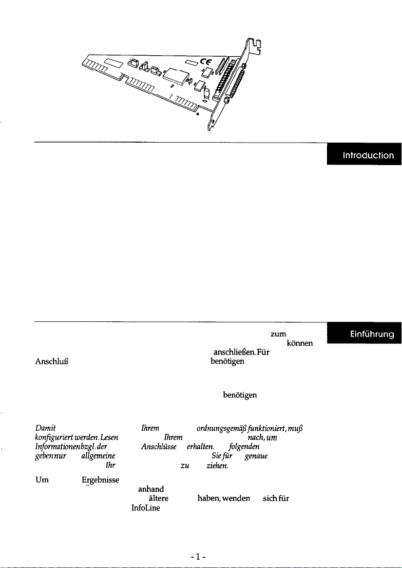
The Bi-directional Parallel Interface Board is designed for use with
IBM®-compatible personal computers. This board can be used only to connect
your computer to an EPSON color image scanner. To connect the board to the
scanner, use a shielded parallel interface cable that has a DB25 (D-sub 25 pin)
male connector on one end and a Centronics®-type 36-pin connector on the other.
To install the interface board in your computer, you will need a crosshead (+)
screwdriver.
Note:
Because you may have to configure this board to operate properly in
your
computer, see
your computer manual® information on its parallel port assignments. Also, the steps
here are general descriptions only, and you may have to see your computer manual for the
proper installation procedure.
For best results, you need Version 1.3 or later of the EPSON Scan! II scanning
software. Check the EPSON Scan! II disk label for the software version number. If
you have an older version, contact your EPSON dealer for information on
updating your software.
Die bidirektionale parallele Schnittstellenkarte ist fiir den Einsatz mit zum
Intel-Standard-kompatiblen PCs konzipiert. Mit dieser Schnittstellenkarte konnen
Sie Ihren Computer nur an EPSON-Farbbildscanner anschliefen. Fur den
paralleles Schnittstellenkabel mit einem 25poligen Sub-D-Steckverbinder (DB25)
an einem und einem 36poligen Centronics-Steckverbinder am anderen Ende.
Zum Einbau der Schnittstellenkarte in Ihren Computer benotigen Sie einen
Kreuzschlitzschraubendreher.
Hinweis:
Sie deshalb in
Computer
Computerhandbuch
sie
Bedienschritte
lnstallationsanleitung
eine allgemeine Beschreibung; deshalb miissen
Computerhandbuch
Rate
die
optimale Ergebnisse zu erzielen, benotigen Sie Version ED-TWAIN 4.7 (fur
Windows 95). Uberpriifen Sie anhand des Diskettenaufklebers die
Versionsnummer. Wenn Sie eine
Version
Sie
em
Update der Software an die InfoLine von EPSON Deutschland.
Mailbox (Direktanwahl):
ISDN: (0211) 50 82-7 77
Analog: (0211) 5 62 14 11
Page 7
La carte d’interface parallele bidirectionnelle a
pour une utilisation
raccorder votre ordinateur
Pour raccorder la carte au digitaliseur, utiliser un cable d’interface
blind6 muni d’un connecteur
d’un connecteur de type
Pour installer la carte d’interface dans votre ordinateur, vous aurez besoin d’un
toumevis en
Remarque:
donnt que
brochure ne donnent que des descriptions
Pour obtenir les meilleurs
version superieure de logiciel EPSON TWAIN. Verifier, dans la boite de dialogue
“A propos de EPSON TWAIN”,
version plus ancienne, veuillez vous mettre en contact avec votre revendeur
EPSON pour obtenir les informations
logiciel.
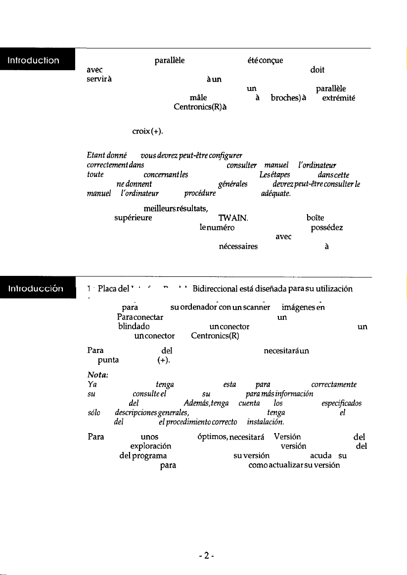
La Placa
ordenadores personales IBM(R) Compatibles. Esta placa solamente puede
utilizarse
EPSON. Para
paralelo blindado que disponga de un conector DB25 (D-sub de 25 patillas) en
extremo y de un conector tipo Centronics(R) de 36 patillas en el otro extremo.
de
de estrella
votre ordinateur, veuillez consulter le manuel de Yordinateur pour
Interface Paralelo Bidirectional
conectar
la placa al scanner, debe utilizar un cable de interface
interface en el ordenador, necesitare un destomillador
un digitaliseur d’images couleurs EPSON.
DB25 (D-Sub
36 broches de l’autre.
confgurer la carte pour qu’elle fonctionne
assignations de ports.
vous devez avoir la version 2.20 ou une
25
et vous deorez peut-&re
de la version. Si vous possedez une
concemant la mise
de
une
reprises
cette
jour du
color
et
en
que es posible que
ordenador,
asignaciones
son
manual
conseguir
software de exploraci6n EPSON Scan! II. Compruebe la versi6n en la etiqueta
disquete
distribuidor EPSON
software.
port paralelo. Ademds, tenga en cuenta que
ordenador el
que configurar
manual de
resultados
EPSON Scan! II. Si
que le asesore sobre
ordenador
placa
quefuncione
sobre sus
pasos aqui
de
la
versi6n es antigua,
1.3 o posterior
a
de
en
Page 8

La scheda d’interfaccia parallela bidirezionale e’
progettata per
l’installazione su personal computer IBM compatibili. Questa scheda puo’ essere
usata per collegare il computer a uno scanner Epson a colori. Per collegare la
scheda
scanner dovete usare un cave di interfaccia parallel0 schermato con
pin) a un’estremita’ e un connettore tipo
Centronics a 36 pin dall’altra.
Per installare la scheda nel computer e’ necessario un cacciavite con la testa a
Consultate la
sia sull’installazionefisica
accompagna il vostro computer per
nel computer,
configurazione
informazioni
parallele.
Per ottenere i migliori risultati dovreste utilizzare la versione 3.1. o successiva
software EpsonScan! II. Verificate sull’etichetta
disco il numero della versione
vostro software. Se avete una versione non aggiomata, contattate il vostro
rivenditore Epson.
Page 9

Unpack the bidirectional board, and hold it by its edges.
Caution:
Do not touch the parts on the board or the board
connector.
Vergewissern Sie sich,
Nehmen Sie niemals die Computerabdeckung ab,
das
der Computer ausgeschaltet und vom Netz getrennt
1.
Attention:
Ne Pas toucher les
Desempaquetelaplaca bidirectional y sujetela
No
Aprite la confezione ed estraete la scheda tenendola per i bordi.
Attenzione:
Non
i circuiti, i componenti o il
de la
carte
de la placa ni
4-
ni son connecteur.
por
der Computer noch an
Page 10

2.
You may need to change the jumper setting on the interface board to match
your computer’s settings. If so, simply lift off the jumper plug (J1) and
reinstall in over the proper pins as shown.
Jumper
J1
J2 Factory use (do not change)
J3 B only (do not change)
Function Factory setting
Select LPT1 or LPT2
LPT2
Open
B
Jumper J1 selects the parallel interface port address: LPT1 or LPT2. In most
cases, the computer is already equipped with a parallel interface port for a
printer and uses the LPT1 setting. Normally, you will not have to change the
board’s default setting, which is LPT2.
2.
urn sie an die Einstellungen Ihres Computers anzupassen. In
nur abzunehmen und
wie dargestellt auf die entsprechenden Pins zu setzen.
Jumper
J2
J3
Mit Jumper 1
entweder
mit einem Port
Werkseitige Einstellung verwenden
Werkseitige Einstellung verwenden
Sie die Port-Adresse
oder LPT2. In den meisten
die parallele Schnittstelle des Druckers ausgeriistet und
benutzt die Einstellung
Funktion
(nicht
(nicht Bndern)
Werkseitige Einstellung
die parallele Schnittstelle aus,
ist der Computer bereits
Normalerweise miissen Sie daher die
werkseitige Einstellung der Schnittstellenkarte (LPT2) nicht
B
Page 11

11 est possible de changer le Gglage de cavalier sur la carte d’interface pour qu’il
et
de I’ins&er sur les
appropri&s, comme
Cavalier
LPTl ou
J2
J3
cavalier
ou LPl2.
d’interface paraWe pour imprimante et il
ne faudra
Position d’usine (Ne pas changer)
B uniquement (Ne pas changer)
de
la plupart des
pas modifier le
l’ordinateur est
par
du port d’interface
le
de la carte, qui
Es posible que tenga que cambiar la configuraci6n de un
interface
retire el cone&or
que
jumper
con la
de su ordenador. Si es
y vuelva a instalarlo sobre
d’un port
d’udne
B
LPTl
Normalement, il
de la placa de
pins
adecuados, tal coma se indica en la ilustraci6n.
original
Selecciona LPTl o
J2
J3
El jtimper
selecciona la direcci6n
muchos cases, el ordenador ya
paralelo para una impresora y utiliza el ajuste
fabricante
(no cambia)
B (no cambia)
port paralelo:
equipado con un port de interface
En general, no
Abierto
B
o LPT2. En
necesario cambiar la configuraci6n por defect0 de la placa, que es LPT2.
Potrebbe
essere
necessario
modificarelaconfigurazione dei jumper
vostro computer.
Per quest0 dovete agire sul jumper consente di selezionare la porta
o LPT2. I jumper J2 e J3 sono impostati in fabbrica e la loro posizione
non deve mai essere modificata.
L’impostazione di default
maggioranza dei computer dove e’ gia presente
e’ LPTZ
impostazione e’ adatta alla grande
parallela LPTI.
-6-
Page 12

Make sure the computer is turned off and unplugged from the AC outlet.
3.
Warning:
Never remove the cover of the computer while it is plugged into a power source.
4.
Disconnect
the keyboard, monitor, and all the cables and peripherals from the
computer, and then move it to a place that will allow sufficient room for
installation.
auf den Steckverbindern.
Trennen Sie die Tastatur, den Monitor sowie alle Kabel und Peripheriegerate
4.
vom Computer und stellen Sie ihn dort auf, wo gentigend Platz fur die
Installation ist.
S’assurer que l’ordinateur est hous tension et debranche de la prise secteur.
3.
Ne jamais
le
de
est
sur une source
4.
l’ordinateur et le
dans un endroit qui permette un acc6s suffisant
pour i’installation de la carte.
Compruebe que el ordenador este desactivado y desconectado de la toma de
3.
corriente CA.
cubierta
4.
Desconecte el teclado, el monitor, y todos
ordenador si
alin
conectado a
cables y perifericos
ordenador, y col6quelo en un lugar con suficiente espacio para realizar
Assicuratevi
3.
il computer sia spent0 e staccaro dalla rete elettrica.
Attenzione:
Non
mai un computer se quest0 2 collegato alla rete elettrica.
4.
disponete
computer su un tavolo con sufficiente spazio per l’installazione.
-7-
de CA.
Page 13

5.
Face the back of the computer, and then remove the retaining screws. Keep the
screws in a safe place while you work on the computer.
. . .
I-
Entfemen Sie
Bewahren Sie die Schrauben an einem sicheren Ort auf, wahrend Sie am
Computer arbeiten.
5.
Se mettre face au dos de l’ordinateur puis retirer les vis de fixations. Ranger les
vis en lieu stir pendant que vous travaillez sur l’ordinateur.
5.
cubierta. Guarde en lugar seguro
ordenador.
Svitate le apposite viti
auf der Computerriickseite
chiudono il computer e
parte posteriore. Conservate le viti in un luogo sicuro.
alle
ordenador y retire
tomillos mientras trabaja en el
sono poste, generaluente,
Schrauben.
tornillos de la
-8-
Page 14

6.
Remove the top cover.
6.
Nehmen Sie die obere Abdeckung des
6.
Retirer
6.
Retire la cubierta
6.
Aprite
computer.
rodenador.
ab.
Page 15

Choose
a
16-bit option slot in which to
install the board,
and slot cover.
die
Installation der Karte einen
und entfemen Sie die Schraube und die
Abdeckung des Schnittstellenschachts.
optionalen
and remove the
screw
Choisir une
fente en option de 16 bits
vis ainsi que la protection de la fente.
el tomillo y la placa que protege la
Scegliete
connettore per schede a 16 bit e togliete la vite e la linguetta
ranura.
connettore.
-10-
dans laquelle installerlacarte et retirer
la
Page 16

Insert the card gently into the slot in the correct direction. If the board does
8.
not seem to fit, do not try to force it. Check the alignment of the
connectors and then reinsert the board.
Schieben Sie die Karte vorsichtig in den Schnittstellenschacht. Wenn die
8.
Karte nicht
Ausrichtung der Steckverbinder und schieben Sie die Karte
ein.
Introduire doucement la carte dans la fente, dans le sens correct. Si la carte
8.
ne semble pas vouloir s’inserer, ne pas essayer de la forcer. Verifier
l’alignement des connecteurs puis reintroduire la carte.
versuchen Sie es nicht mit Gewalt.
Sie die
I
Inserte con cuidado la placa en la ranura en la
8.
no entra, no la fuerce. Compruebe la alineacion de
reinserte la placa.
Inserite la scheda nel connettore: se incontrate delle difficolta, non
8.
scheda ma verificate l’allineamento dei connettori.
correcta. Si la placa
conectores y
I
Page 17

Be sure that it is firmly seated
in the slot.
Secure the board with the screw you removed from the slot cover.
9.
Vergewissem Sie sich,
sie fest im Schnittstellenschacht sitzt.
Schrauben Sie die Karte mit der Schraube fur die Abdeckung des
Schnittstellenschachts fest.
9.
S’assurer qu’elle soit bien ancr6e dans la fente.
Fixer la carte au moyen de las vis qui servait
maintenir la protection de la
fente.
Asegure la placa con el tomillo que ha retirado de la placa de proteccidn de
la ranura.
Assicuratevi
sia inserita completamente.
Fissate la scheda con l’apposita vite.
- 12 -
Page 18

screws.
10.
Computers wieder auf und schrauben
Sie die mit den verbliebenen Schrauben fest.
10.
Remonter le capot
de l’ordinateur et l’attacher avec les vis de
fixation.
10.
Coloque de nuevo la cubierta
10.
Chiudete il computer e riawitate le viti di chiusura.
ordenador y
con sus tomillos.
I
Page 19

11.
Reconnect
the keyboard, monitor, and peripherals to the computer. Make sure
you use a properly shielded parallel interface cable to connect the
bidirectional interface board to your scanner. Next, reconnect the computer
and peripherals to power outlets.
11.
Computer an. Vergewissem Sie
Sie ein ordnungsgem;if
geschirmtes paralleles Kabel verwenden, urn die bidirektionale
Schnittstellenkarte an Ihren Scanner
SchlieBen Sie nun den
Computer und die Peripheriegerate wieder an das Netz an.
11.
Rebrancher
Veiller
clavier, le moniteur video et les peripheriques
l’ordinateur.
utiliser un cable d’interface parallele correctement blind6 pour
raccorder la carte d’interface bidirectionnelle au digitaliseur. Ensuite,
rebrancher l’ordinateur et les peripheriques sur les prises secteur.
11.
Conecte de nuevo el monitor, el teclado y
Comoruebe
la
nuevo el ordenador y
interface
un cable de interface
perifericos a sus tomas de corriente CA.
al scanner: A continuaci6n,
perifericos al ordenador.
blindado
conectar
de
Collegate nuovamente tastiera, monitor e tutti i cavi di collegamento alle
periferiche. Coilegate lo scanner utilizzando un cave di mterfaccia parallel0
schermato dotato di un connettore maschio DB25 (D-sub 25 pin) a
quindi il computer e le periferiche alla rete elettrica.
- 14 -
Page 20

12.
Turn on the computer and check to see that it operates correctly.
Note:
lf you have a diagnostic program for the computer, run it before starting up
the entire system to ensure that the board was installed correctly.
12.
Schalten Sie den Computer ein und
Sie, ob er ordnungsgemlf?,
arbeitet.
Hinweis:
ein Priifprogrammjir den Computer
erst
das
12.
Mettre l’ordinateur sous tension et v&ifier qu’il fonctionne correctement.
die
System.
korrekt
Sie es
ist und
Remarque:
Si vous poss6dez un programme de diagnostique pour l’ordinateur, l’ex&uter
avant de
12.
Active el ordenador para comprobar su funciona correctamente.
tout
systhne pour
certain que la
est
Sie
Si tiene
12.
Accendete il computer e verificate
de
totalmente el sistema para de
el order&~*
con,.
funzioni correttamente.
Se disponete di un programma di diagnosi, eseguitelo per verificare
non
dei
Page 21

13.
Run your scanner software program as a final check.
13.
Lancer le programme du logiciel du digitaliseur pour une verification finale.
13.
Como
final,
-16-
el
scanner.
Page 22

I
EPSON OVERSEAS MARKETlNG LOCATlONS
I
EPSON AMERICA, INC.
20770 Madrona Ave.
P.O. Box 2842
Torrance, CA 90509-2642
Phone: (600) 922-6911
Fax: (310) 762-5220
EPSON DEUTSCHLAND
6.
40549
Phone: (0211) 56030
Telex: 6564766
Germany
EPSON AUSTRALIA PTY. LTD.
70
Phone:
Fax: 2-9903-9177
STREET, CHATSWOOD 2067 NSW.
EPSON HONG KONG LTD.
Rooms 4706-10,47/F,
China Resources Bldg.,
26
Phone:
Fax:
EPSON
20099 Sesto
MI, Italy
Phone: 2-262331
Fax: 2-2440750
Road, Wanchai, Hong Kong
Casiraghi 427
EPSON UK LTD.
Campus 100. Maylands Avenue,
Hemel Hempstead, Herts.
HP2 7TJ, U.K.
Phone: (+44) 01442 61144
Fax: (+44) 01442 227227
EPSON FRANCE S.A.
66 bis, rue Marjolin
92300, Levallois-Perret, France
Phone:
Telex: 610657
EPSON SINGAPORE PTE. LTD.
No. 1 Temasek Avenue
Tower, Singapore 039192
Phone: (065) 33 77 911
Fax: (065) 33 41 165
EPSON TAIWAN TECHNOLOGY
TRADING LTD.
No. 267
Taipei, Taiwan, R.O.C.
Phone: (02) 717-7360
Fax: (02) 712-9164
EPSON
Av. de Roma, 16-26
06290 Cerdanyola del
Barcelona, Spain
Phone: 562. 15.00
Fax: 562. 15.55
E. Road, Sec. 3,
S.A.
SEIKO EPSON
(Hlrooka Office)
60 Harashinden. Hirooka
Shiojiri-shi, Nagano-ken
399-07 Japan Fax: (02) 996 14 11
EPSON PORTUGAL, S.A.
R. do
4460 Matosinhos, Portugal
Phone: (02) 996 14 02
471, 1” Perafiia
1996 October
Page 23

EPSON
 Loading...