

Page 1
SERVICE MANUAL
Color Inkjet Printer
EPSON B-300/B-308
EPSON B-500DN/B-508DN
EPSON B-310N/B-318N
EPSON B-510DN/B-518DN
Confidential
SEIJ07-013
Page 2

Notice:
All rights reserved. No part of this manual may be reproduced, stored in a retrieval system, or transmitted in any form or by any means, electronic, mechanical,
photocopying, recording, or otherwise, without the prior written permission of SEIKO EPSON CORPORATION.
The contents of this manual are subject to change without notice.
All effort have been made to ensure the accuracy of the contents of this manual. However, should any errors be detected, SEIKO EPSON would greatly appreciate being
informed of them.
The above not withstanding SEIKO EPSON CORPORATION can assume no responsibility for any errors in this manual or the consequences thereof.
EPSON is a registered trademark of SEIKO EPSON CORPORATION.
General Notice: Other product names used herein are for identification purpose only and may be trademarks or registered trademarks of their
respective owners. EPSON disclaims any and all rights in those marks.
Copyright © 2009 SEIKO EPSON CORPORATION.
IJP LP CS Quality Assurance Department
Confidential
Page 3

PRECAUTIONS
Precautionary notations throughout the text are categorized relative to 1) Personal injury and 2) damage to equipment.
DANGER Signals a precaution which, if ignored, could result in serious or fatal personal injury. Great caution should be exercised in performing procedures preceded by
DANGER Headings.
WARNING Signals a precaution which, if ignored, could result in damage to equipment.
The precautionary measures itemized below should always be observed when performing repair/maintenance procedures.
DANGER
1. ALWAYS DISCONNECT THE PRODUCT FROM THE POWER SOURCE AND PERIPHERAL DEVICES PERFORMING ANY MAINTENANCE OR REPAIR
PROCEDURES.
2. NO WORK SHOULD BE PERFORMED ON THE UNIT BY PERSONS UNFAMILIAR WITH BASIC SAFETY MEASURES AS DICTATED FOR ALL ELECTRONICS
TECHNICIANS IN THEIR LINE OF WORK.
3. WHEN PERFORMING TESTING AS DICTATED WITHIN THIS MANUAL, DO NOT CONNECT THE UNIT TO A POWER SOURCE UNTIL INSTRUCTED TO DO
SO. WHEN THE POWER SUPPLY CABLE MUST BE CONNECTED, USE EXTREME CAUTION IN WORKING ON POWER SUPPLY AND OTHER ELECTRONIC
COMPONENTS.
4. WHEN DISASSEMBLING OR ASSEMBLING A PRODUCT, MAKE SURE TO WEAR GLOVES TO AVOID INJURIER FROM METAL PARTS WITH SHARP EDGES.
WARNING
1. REPAIRS ON EPSON PRODUCT SHOULD BE PERFORMED ONLY BY AN EPSON CERTIFIED REPAIR TECHNICIAN.
2. MAKE CERTAIN THAT THE SOURCE VOLTAGES IS THE SAME AS THE RATED VOLTAGE, LISTED ON THE SERIAL NUMBER/RATING PLATE. IF THE
EPSON PRODUCT HAS A PRIMARY AC RATING DIFFERENT FROM AVAILABLE POWER SOURCE, DO NOT CONNECT IT TO THE POWER SOURCE.
3. ALWAYS VERIFY THAT THE EPSON PRODUCT HAS BEEN DISCONNECTED FROM THE POWER SOURCE BEFORE REMOVING OR REPLACING PRINTED
CIRCUIT BOARDS AND/OR INDIVIDUAL CHIPS.
4. IN ORDER TO PROTECT SENSITIVE MICROPROCESSORS AND CIRCUITRY, USE STATIC DISCHARGE EQUIPMENT, SUCH AS ANTI-STATIC WRIST
STRAPS, WHEN ACCESSING INTERNAL COMPONENTS.
5. REPLACE MALFUNCTIONING COMPONENTS ONLY WITH THOSE COMPONENTS BY THE MANUFACTURE; INTRODUCTION OF SECOND-SOURCE ICs OR
OTHER NON-APPROVED COMPONENTS MAY DAMAGE THE PRODUCT AND VOID ANY APPLICABLE EPSON WARRANTY.
6. WHEN USING COMPRESSED AIR PRODUCTS; SUCH AS AIR DUSTER, FOR CLEANING DURING REPAIR AND MAINTENANCE, THE USE OF SUCH
PRODUCTS CONTAINING FLAMMABLE GAS IS PROHIBITED.
Confidential
Page 4
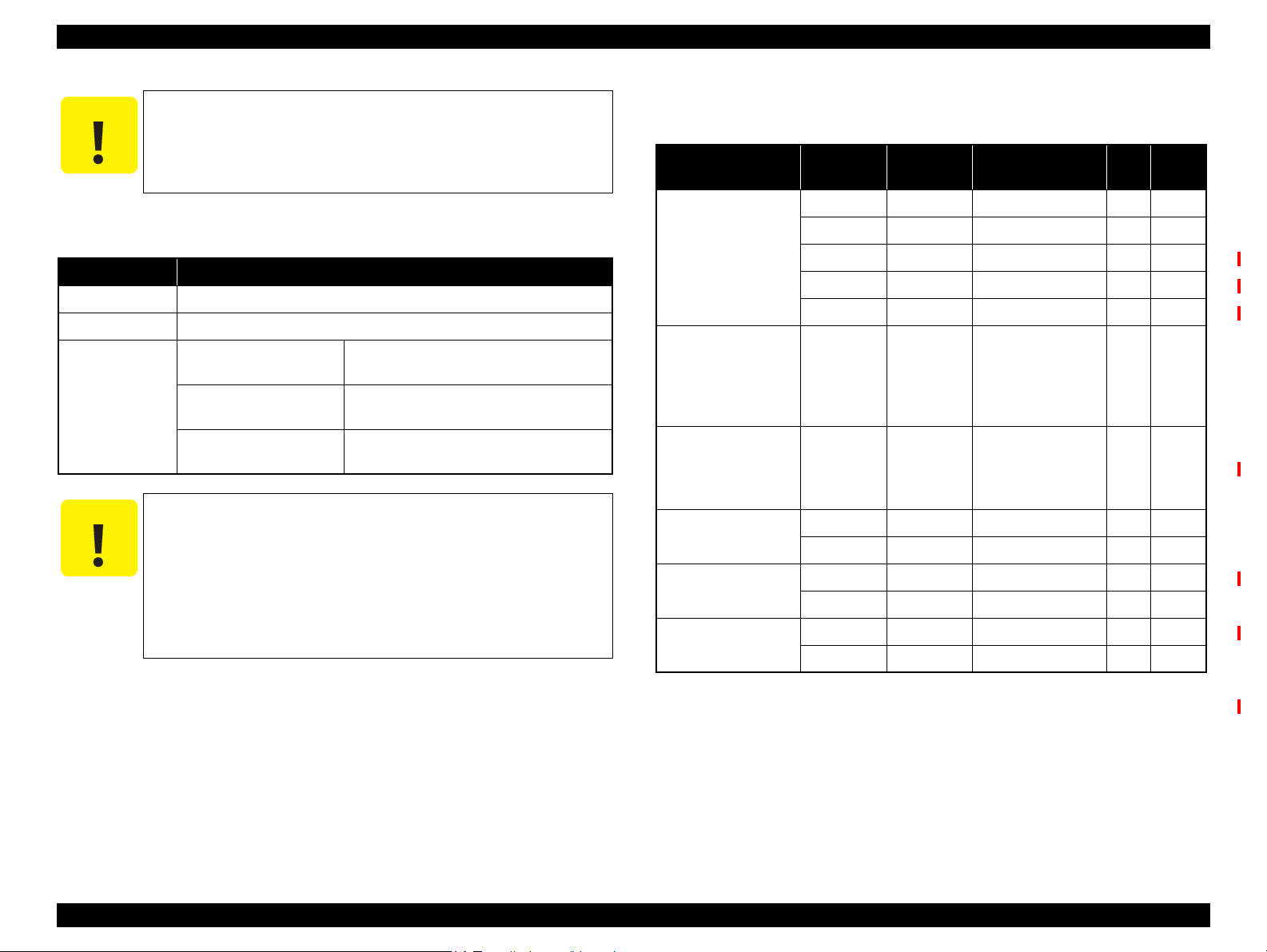
About This Manual
CAUTION
CHECK
POINT
REASSEMBLY
This manual describes basic functions, theory of electrical and mechanical operations, maintenance and repair procedures of the printer. The instructions and procedures included
herein are intended for the experienced repair technicians, and attention should be given to the precautions on the preceding page.
Manual Configuration
This manual consists of six chapters and Appendix.
CHAPTER 1.PRODUCT DESCRIPTIONS
Provides a general overview and specifications of the product.
CHAPTER 2.OPERATING PRINCIPLES
Describes the theory of electrical and mechanical operations of the
product.
CHAPTER 3.TROUBLESHOOTING
Describes the step-by-step procedures for the troubleshooting.
CHAPTER 4.DISASSEMBLY / ASSEMBLY
Describes the step-by-step procedures for disassembling and assembling
the product.
CHAPTER 5.ADJUSTMENT
Provides Epson-approved methods for adjustment.
CHAPTER 6.MAINTENANCE
Provides preventive maintenance procedures and the lists of Epsonapproved lubricants and adhesives required for servicing the product.
APPENDIX Provides the following additional information for reference:
• Connector Summary
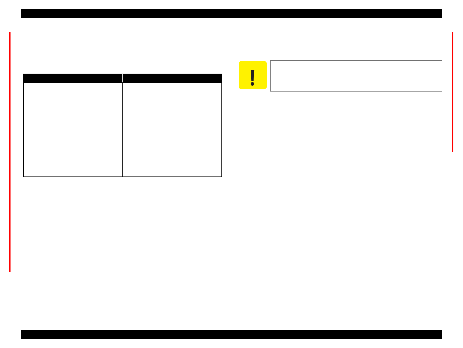
Symbols Used in this Manual
Various symbols are used throughout this manual either to provide additional
information on a specific topic or to warn of possible danger present during a
procedure or an action. Be aware of all symbols when they are used, and always read
NOTE, CAUTION, or WARNING messages.
ADJUSTMENT
REQUIRED
WARNING
Indicates an operating or maintenance procedure, practice or condition
that is necessary to keep the product’s quality.
Indicates an operating or maintenance procedure, practice, or condition
that, if not strictly observed, could result in damage to, or destruction of,
equipment.
May indicate an operating or maintenance procedure, practice or
condition that is necessary to accomplish a task efficiently. It may also
provide additional information that is related to a specific subject, or
comment on the results achieved through a previous action.
Indicates an operating or maintenance procedure, practice or condition
that, if not strictly observed, could result in injury or loss of life.
Indicates that a particular task must be carried out according to a certain
standard after disassembly and before re-assembly, otherwise the quality of the components in question may be adversely affected.
Confidential
Page 5

Revision Status
Revision Date of Issue Description
A April 1, 2008 First Release
B May 16, 2008 Revised Contents
Chapter 3
Descriptions have been added in Table 3-26 “Troubleshooting Ink Suction / Waste Ink Problems” (p70).
Chapter 4
Made changes in 4.1.2 Tools (p75).
Made changes in 4.3.4 Using Acetate Tape (p80).
Made changes in 4.5.6.2 Front Housing Assy (p92).
Made changes in 4.5.7.2 Upper Housing (p94).
Made changes in 4.5.7.3 Cover Open Sensor (p96).
Made changes in 4.6.3 AID Board (p100).
Made changes in 4.6.5 Power Supply Unit (p106).
Made changes in 4.7.1.1 IC Holder Assy (p108).
Made changes in 4.7.1.3 CV Drive Assy (p116).
“CAUTION” has been added in 4.7.3.1 Printhead (p121).
Made changes in 4.7.3.3 APG Assy / Sub Board (p125).
Made changes in 4.7.3.4 ASF Encoder Assy (p128).
Made changes in 4.7.3.5 CR Motor (p129).
Made changes in 4.7.3.6 Carriage Assy (p131).
Made changes in 4.7.4.3 ASF Motor Assy (p136).
Made changes in 4.7.4.4 Planet Lock Assy (p138).
Made changes in 4.7.4.9 Paper Guide Bank Assy (p149).
Made changes in 4.7.5.1 PF Motor (p156).
Made changes in 4.7.5.5 Front Paper Guide & EJ Roller Assy (p162).
Made changes in 4.7.6.1 Ink System (p165).
Made changes in 4.7.6.2 EJ Waste Ink Assy (p168).
Made changes in 4.7.6.3 EJC Sensor (p169).
Chapter 5
Made changes in Table 5-1 “Adjustment Items and Overviews” (p171).
Descriptions have been added in Table 5-2 “Maintenance Items” (p174).
Descriptions have been added in Table 5-3 “Additional Functions” (p175).
Made changes in 5.2.6 Head angular adjustment (p181).
Confidential
Page 6

Revision Date of Issue Description
C March 31, 2009 Revised Contents
Chapter 1
Descriptions have been added in Table 1-12 “Power Supply Specifications” (p20).
Chapter 3
Descriptions have been added in Table 3-23 “Troubleshooting Print Quality Problems” (p67).
Descriptions have been added in Table 3-25 “Troubleshooting Ink Supply Problems” (p69).
Chapter 4
Descriptions have been added in 4.3.1 Releasing Carriage Lock (p79).
“REASSEMBLY” has been added in 4.7.1.1 IC Holder Assy (p108).
“REASSEMBLY” has been added in 4.7.1.3 CV Drive Assy (p116).
Chapter 5
Made changes in Table 5-1 “Adjustment Items and Overviews” (p171).
Made changes in Table 5-4 “Adjustment Items” (p176).
Made changes in 5.2.6 Head angular adjustment (p181).
Made changes in 5.2.7 AID inspection (p184).
Descriptions have been added in 5.2.10 Paper Skew Adjustment (p187).
Descriptions have been added in 5.2.11 ACL Failed Counter Initialization (p189).
Chapter 6
Descriptions have been added in Table 6-2 “Specified Lubricant” (p198).
Confidential
Page 7

Revision Date of Issue Description
D September 17, 2009 Revised Contents
Chapter 2
Made changes in Figure 2-1 “Printer Mechanism Block Diagram” (p31).
Made changes in Table 2-1 “PG Settings / Cam Diagram” (p32).
Descriptions have been added in 2.3 Optical Sensor Control (p34).
Chapter 3
Made changes in Table 3-3 “Error Messages and Possible Causes” (p37).
Descriptions have been added in 3.3.2 Fatal Error (p48).
Chapter 4
Made changes in 4.7.3.1 Printhead (p121).
“ADJUSTMENT REQUIRED” has been changed in 4.7.3.5 CR Motor (p129).
“ADJUSTMENT REQUIRED” has been changed in 4.7.5.1 PF Motor (p156).
Chapter 5
Made changes in Table 5-1 “Adjustment Items and Overviews” (p171).
Descriptions have been added in Table 5-2 “Maintenance Items” (p174).
“CHECKPOINT” has been added and made changes in 5.2.11 ACL Failed Counter Initialization (p189).
Made changes in 5.3.2 PF Belt Tension Adjustment (p193).
Made changes in 5.3.3 FD Belt Tension Adjustment (p194).
Confidential
Page 8

Revision Date of Issue Description
E November 26, 2009 Revised Contents
All chapters
Descriptions about B-310N/B-318N/B-510DN/B-518DN are added.
Chapter 1
Made changes in 1.1 Features (p14)
Made changes in Table 1-3 “Product No. of Ink Cartridges” (p15)
Made changes in Table 1-6 “Print Mode (Color/Monochrome)” (p16)
Made changes in Table 1-7 “Supported Paper” (p17)
Made changes in Table 1-12 “Power Supply Specifications” (p20)
Made changes in Table 1-14 “Operation Buttons, LED, LCD (B-500DN/B-508DN/B-310N/B-318N/B-510DN/B-
518DN)” (p22)
Made changes in Table 1-16 “LEDs and LCD Indications” (p23)
1.6 Various Settings (p24) has been added
Made changes in Figure 1-10 “Network Status Sheet Sample (2)” (p29)
Chapter 3
Made changes in Table 3-3 “Error Messages and Possible Causes” (p37)
Made changes in Table 3-12 “Check Point for Fatal Error of Each Phenomenon” (p52)
Made changes in Table 3-19 “FFC/harness Connection Error (SUB Board)” (p65)
Confidential
Page 9

Revision Date of Issue Description
E November 26, 2009
Chapter 4
“CHECKPOINT” has been added and made changes in 4.4.3 Cassette Assy (p85)
Made changes in 4.5.6.2 Front Housing Assy (p92)
Made changes in 4.6.2 Network Board (B-500DN/B-508DN/B-310N/B-318N/B-510DN/B-518DN only) (p99)
Made changes in 4.6.3 AID Board (p100)
Made changes in 4.7.1.1 IC Holder Assy (p108)
Made changes in 4.7.1.3 CV Drive Assy (p116)
Made changes in 4.7.2 Lower Housing (p117)
“CHECKPOINT” has been added and made changes in 4.7.3.1 Printhead (p121)
“CHECKPOINT” has been added and made changes in 4.7.3.3 APG Assy / Sub Board (p125)
“CHECKPOINT” has been added in 4.7.3.4 ASF Encoder Assy (p128)
“CHECKPOINT” has been added and made changes in 4.7.4.4 Planet Lock Assy (p138)
“CHECKPOINT” has been added in 4.7.4.5 ASF Sub Encoder (p142)
Made changes in 4.7.4.6 Retard Transfer Assy (p143)
Made changes in 4.7.4.7 FASF Retard Assy (p144)
“CHECKPOINT” has been added and made changes in 4.7.5.4 Left/Right Upper Paper Guide (p160)
Made changes in 4.7.6.1 Ink System (p165)
Chapter 5
Made changes in Table 5-3 “Additional Functions” (p175)
Chapter 6
Made changes in Table 6-2 “Specified Lubricant” (p198)
Made changes in 6.1.3 Lubrication (p198)
Chapter 7
Made changes in Figure 7-1 “Block Diagram” (p208)
Confidential
Page 10

EPSON B-300/B-308/B-500DN/B-508DN/B-310N/B-318N/B-510DN/B-518DN Revision E
Contents
Chapter 1 PRODUCT DESCRIPTION
1.1 Features............................................................................................................... 14
1.2 Printing Specifications........................................................................................ 15
1.2.1 Basic Specifications................................................................................. 15
1.2.2 Ink Cartridges .......................................................................................... 15
1.2.3 Maintenance Box..................................................................................... 16
1.2.4 Print Mode ............................................................................................... 16
1.2.5 Supported Paper....................................................................................... 17
1.2.6 Printing Area ........................................................................................... 19
1.3 Interface.............................................................................................................. 19
1.3.1 USB Interface .......................................................................................... 19
1.3.2 Network Interface
(B-500DN/B-508DN/B-310N/B-318N/B-510DN/B-518DN only) .......... 19
1.4 General Specifications........................................................................................ 20
1.4.1 Electrical Specifications .......................................................................... 20
1.4.2 Safety Approvals (Safety standards/EMI) ............................................... 20
1.4.3 Environmental Conditions....................................................................... 21
1.4.4 Durability................................................................................................. 21
1.5 Control Panel ...................................................................................................... 22
1.5.1 Operation Buttons.................................................................................... 22
1.5.2 LEDs and LCD Indications ..................................................................... 23
1.6 Various Settings.................................................................................................. 24
1.6.1 Panel Operation ....................................................................................... 24
1.6.1.1 Menu Configuration
(B-500DN/B-508DN/B-310N/B-318N/B-510DN/B-518DN only) .... 24
1.6.1.2 Panel Operation Lock Setting
(B-310N/B-318N/B-510DN/B-518DN only) ...................................... 25
1.6.1.3 Forced Power OFF ............................................................................. 26
1.6.2 AID Function Setting .............................................................................. 26
1.6.2.1 AID Detection Cleaning
(B-310N/B-318N/B-510DN/B-518DN only) ...................................... 26
1.6.2.2 AID High Quality Mode/Dot Missing Tolerance Mode .................... 27
1.6.2.3 Monochrome Priority Mode ............................................................... 27
1.6.3 Low Speed Mode (MPBF Priority Mode)
(B-310N/B-318N/B-510DN/B-518DN only)............................................ 28
1.7 Status Sheet ........................................................................................................ 28
Chapter 2 Operating Principles
2.1 Overview ............................................................................................................ 31
2.1.1 Printer Mechanism .................................................................................. 31
2.1.2 Printhead.................................................................................................. 31
2.1.3 PG Setting................................................................................................ 32
2.2 Motors and Sensors ............................................................................................ 33
2.3 Optical Sensor Control ....................................................................................... 34
Chapter 3 Troubleshooting
3.1 Overview ............................................................................................................ 36
3.1.1 Troubleshooting on Motors and Sensors................................................. 36
3.2 Error Messages and Possible Causes.................................................................. 37
3.2.1 List of Error Indications .......................................................................... 37
3.3 Troubleshooting.................................................................................................. 39
3.3.1 Troubleshooting by Error Message ......................................................... 39
3.3.2 Fatal Error................................................................................................ 48
3.3.2.1 Check Point for Fatal Error of Each Phenomenon ............................. 52
3.3.2.2 Check Result of Fatal Errors when Abnormality Occurs................... 60
3.4 Troubleshooting by Symptom (no error indications)......................................... 66
3.4.1 Troubleshooting Printer Mechanism Problems....................................... 66
3.4.2 Troubleshooting Electrical Problems ...................................................... 68
3.4.3 Troubleshooting Ink Supply / Waste Ink Problems ................................ 69
3.4.4 Troubleshooting I/F-related Problems..................................................... 71
3.5 Troubleshooting Duplex Unit Problems............................................................. 72
10
Confidential
Page 11

EPSON B-300/B-308/B-500DN/B-508DN/B-310N/B-318N/B-510DN/B-518DN Revision E
Chapter 4 Disassembly and Assembly
4.1 Overview ............................................................................................................ 74
4.1.1 Precautions .............................................................................................. 74
4.1.2 Tools ........................................................................................................ 75
4.1.3 Screws...................................................................................................... 75
4.1.4 Work Completion Checklist .................................................................... 75
4.1.5 Preparation for Disassembling ................................................................ 76
4.1.6 Orientation Definition ............................................................................. 76
4.2 Disassembly Flowchart ...................................................................................... 77
4.3 Basic Operations................................................................................................. 79
4.3.1 Releasing Carriage Lock ......................................................................... 79
4.3.2 Handling Ink Supply Parts....................................................................... 80
4.3.3 Handling Ink System Parts ...................................................................... 80
4.3.4 Using Acetate Tape ................................................................................. 80
4.3.5 Protection for Transportation .................................................................. 81
4.4 Consumables & Accessories .............................................................................. 83
4.4.1 Ink Cartridge............................................................................................ 83
4.4.2 Maintenance Box Assy............................................................................ 84
4.4.3 Cassette Assy........................................................................................... 85
4.4.4 Rear Cover / Duplex Unit........................................................................ 86
4.5 Removing Exterior Parts .................................................................................... 87
4.5.1 IC Holder Cover ...................................................................................... 87
4.5.2 Cover Ink Eject Box ................................................................................ 88
4.5.3 Front ASF Cover Assy ............................................................................ 88
4.5.4 Stacker Assy / Paper Support .................................................................. 89
4.5.4.1 Stacker Assy ....................................................................................... 89
4.5.4.2 Paper Support ..................................................................................... 89
4.5.5 Panel Unit ................................................................................................ 90
4.5.6 Cover Printer Assy /Housing Front Assy ................................................ 91
4.5.6.1 Cover Printer Assy ............................................................................. 91
4.5.6.2 Front Housing Assy............................................................................ 92
4.5.7 Connector Cover / Upper Housing .......................................................... 94
4.5.7.1 Connector Cover................................................................................. 94
4.5.7.2 Upper Housing ................................................................................... 94
4.5.7.3 Cover Open Sensor............................................................................. 96
4.6 Removing the Circuit Boards ............................................................................. 97
4.6.1 Main Board .............................................................................................. 97
4.6.2 Network Board
(B-500DN/B-508DN/B-310N/B-318N/B-510DN/B-518DN only) .......... 99
4.6.3 AID Board ............................................................................................. 100
4.6.4 Disassembling the Panel Unit................................................................ 103
4.6.4.1 Panel Board ...................................................................................... 104
4.6.4.2 Optical Tube, Buttons ...................................................................... 105
4.6.5 Power Supply Unit ................................................................................ 106
4.7 Removing the Printer Major Components........................................................ 108
4.7.1 Removing the Ink System Components ................................................ 108
4.7.1.1 IC Holder Assy................................................................................. 108
4.7.1.2 Sub-B Board..................................................................................... 115
4.7.1.3 CV Drive Assy ................................................................................. 116
4.7.2 Lower Housing ...................................................................................... 117
4.7.3 Disassembling the Carriage Components.............................................. 121
4.7.3.1 Printhead........................................................................................... 121
4.7.3.2 CR Scale ........................................................................................... 124
4.7.3.3 APG Assy / Sub Board..................................................................... 125
4.7.3.4 ASF Encoder Assy ........................................................................... 128
4.7.3.5 CR Motor.......................................................................................... 129
4.7.3.6 Carriage Assy ................................................................................... 131
4.7.4 Disassembling the Paper Loading Mechanism Components ................ 133
4.7.4.1 Rear ASF Assy ................................................................................. 133
4.7.4.2 RH Sensor / RP Sensor.................................................................... 135
4.7.4.3 ASF Motor Assy............................................................................... 136
4.7.4.4 Planet Lock Assy.............................................................................. 138
4.7.4.5 ASF Sub Encoder ............................................................................. 142
4.7.4.6 Retard Transfer Assy........................................................................ 143
4.7.4.7 FASF Retard Assy............................................................................ 144
4.7.4.8 LD Roller / Retard Roller................................................................. 146
4.7.4.9 Paper Guide Bank Assy.................................................................... 149
4.7.4.10 PEF Sensor ..................................................................................... 153
4.7.4.11 PER Sensor..................................................................................... 153
4.7.4.12 Rear Paper Guide / PE Sensor....................................................... 154
4.7.4.13 Pick-up Assy .................................................................................. 155
4.7.5 Disassembling the Paper Feed Mechanism Components...................... 156
4.7.5.1 PF Motor .......................................................................................... 156
4.7.5.2 PF Encoder ....................................................................................... 158
4.7.5.3 EJ Frame Assy.................................................................................. 159
4.7.5.4 Left/Right Upper Paper Guide ......................................................... 160
4.7.5.5 Front Paper Guide & EJ Roller Assy ............................................... 162
4.7.5.6 PF Roller Assy ................................................................................. 163
4.7.6 Disassembling the Ink System Components ......................................... 165
11
Confidential
Page 12

EPSON B-300/B-308/B-500DN/B-508DN/B-310N/B-318N/B-510DN/B-518DN Revision E
4.7.6.1 Ink System. ....................................................................................... 165
4.7.6.2 EJ Waste Ink Assy. ........................................................................... 168
4.7.6.3 EJC Sensor . ...................................................................................... 169
Chapter 5 ADJUSTMENT
5.1 Adjustment Items and Overview ...................................................................... 171
5.1.1 Servicing Adjustment Item List............................................................. 171
5.1.2 Required Adjustments . .......................................................................... 176
5.2 Adjustment by Using Adjustment Program ..................................................... 178
5.2.1 Top Margin Adjustment (Rear/Front) ................................................... 178
5.2.2 Bi-D Adjustment ................................................................................... 178
5.2.3 First Dot Position Adjustment (Front/Rear). ......................................... 179
5.2.4 PW Adjustment ..................................................................................... 179
5.2.5 PF Adjustment (Rear/Front) .................................................................. 180
5.2.6 Head angular adjustment ....................................................................... 181
5.2.7 AID inspection. ...................................................................................... 184
5.2.8 Printer Mechanism Operation Check .................................................... 184
5.2.9 MAC Address Setting (B-500DN/B-508DN/B-310N/B-318N/B-510DN/
B-518DN only) ........................................................................................ 185
5.2.10 Paper Skew Adjustment . ..................................................................... 187
5.2.11 ACL Failed Counter Initialization....................................................... 189
5.2.12 Compulsion Uni-d Print Setting .......................................................... 190
5.3 Adjustment without Using Adjustment Program ............................................. 191
5.3.1 PG Adjustment ...................................................................................... 191
5.3.2 PF Belt Tension Adjustment ................................................................. 193
5.3.3 FD Belt Tension Adjustment. ................................................................ 194
Chapter 7 APPENDIX
7.1 Connector Summary. ........................................................................................ 208
Chapter 6 MAINTENANCE
6.1 Overview .......................................................................................................... 196
6.1.1 Cleaning. ................................................................................................ 196
6.1.2 Service Maintenance ............................................................................. 197
6.1.2.1 Printhead cleaning ............................................................................ 197
6.1.2.2 Service Call ...................................................................................... 197
6.1.3 Lubrication ............................................................................................ 198
12
Confidential
Page 13

PRODUCT DESCRIPTION
CHAPTER
1
Confidential
Page 14
EPSON B-300/B-308/B-500DN/B-508DN/B-310N/B-318N/B-510DN/B-518DN Revision E
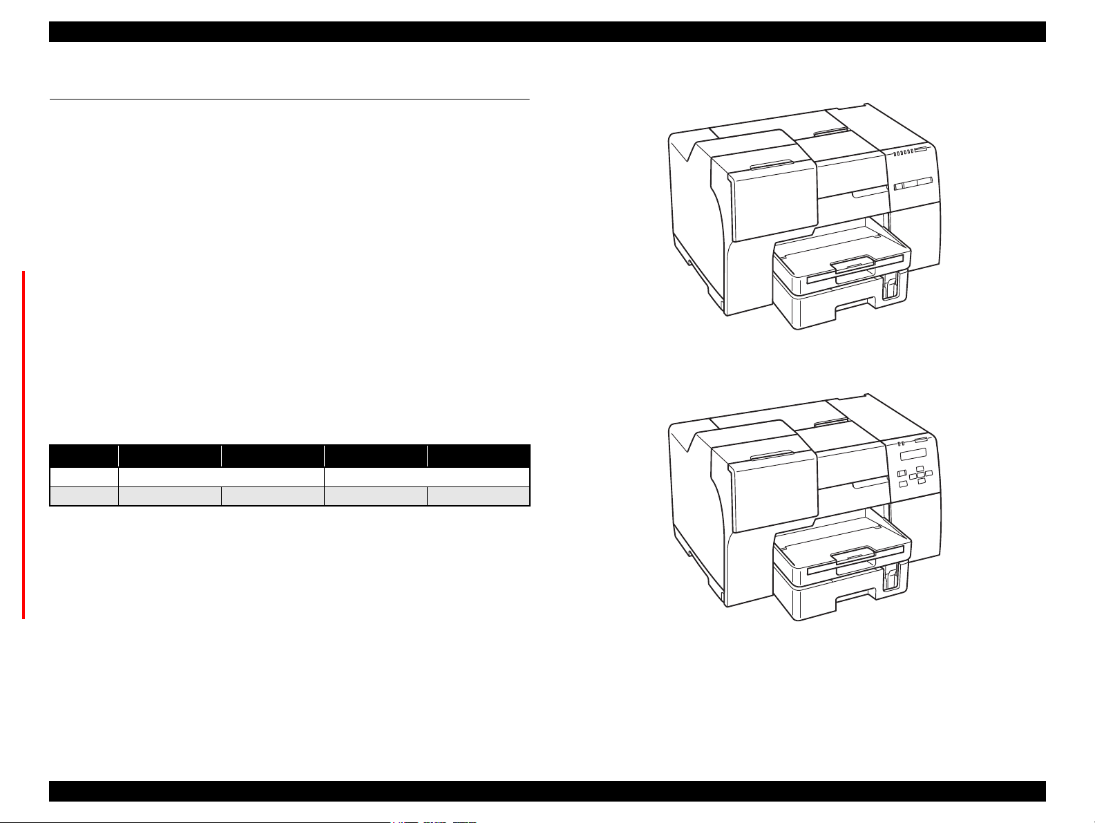
B-300/B-308
B-500DN/B-508DN/B-310N/B-318N/B-510DN/B-518DN
1.1 Features
B-300/B-308/B-500DN/B-508DN/B-310N/B-318N/B-510DN/B-518DN is businessoriented A4 inkjet printers, which offers high print quality and high durability with low
running costs like laser printers. The main features are:
F-Mach Turbo 2 (180 nozzles x 8 columns) Printhead
High durability (up to 100,000 sheets can be printed)
The default mode enables high-speed printing on plain paper
Large capacity ink cartridges
Large capacity paper feeders (front: 500 sheets, rear: 150 sheets)
Automatic duplex printing using the duplex unit
(B-500DN/B-508DN/B-510DN/B-518DN include the unit as standard. For B-300/
B-308/B-310N/B-318N, the unit is available as an option.)
2 Line LCD on the control panel offers high level of visibility and operability.
(B-500DN/B-508DN/B-310N/B-318N/B-510DN/B-518DN only)
Wired LAN is supported.
(B-500DN/B-508DN/B-310N/B-318N/B-510DN/B-518DN only)
Dimensions & Weight
Table 1-1. Dimensions & Weight
B-300/B-308 B-310N/B-318N
Dimensions
Weight 9.85 kg
480 mm (W) x 420 mm (D) x 312 mm (H)*1480 mm (W) x 489 mm (D) x 312 mm (H)
*3
9.95 kg
*3
B-500DN/B-508DN B-510DN/B-518DN
*3
10.69 kg
10.70 kg*4/10.79 kg
*2
*5
*1:The optional duplex unit is not included. The stackers are retracted.
*2:The duplex unit is included. The stackers are retracted.
*3:The ink cartridges, the power cord and the duplex unit are not included.
*4:The ink cartridges and the power cord are not included.
*5:For the EAI model, the ink cartridges, the power cord, and the Casstte Assy are not
included, but the Cassette Assy for legal size paper is included instead.
Figure 1-1. External View
PRODUCT DESCRIPTION Features 14
Confidential
Page 15
EPSON B-300/B-308/B-500DN/B-508DN/B-310N/B-318N/B-510DN/B-518DN Revision E
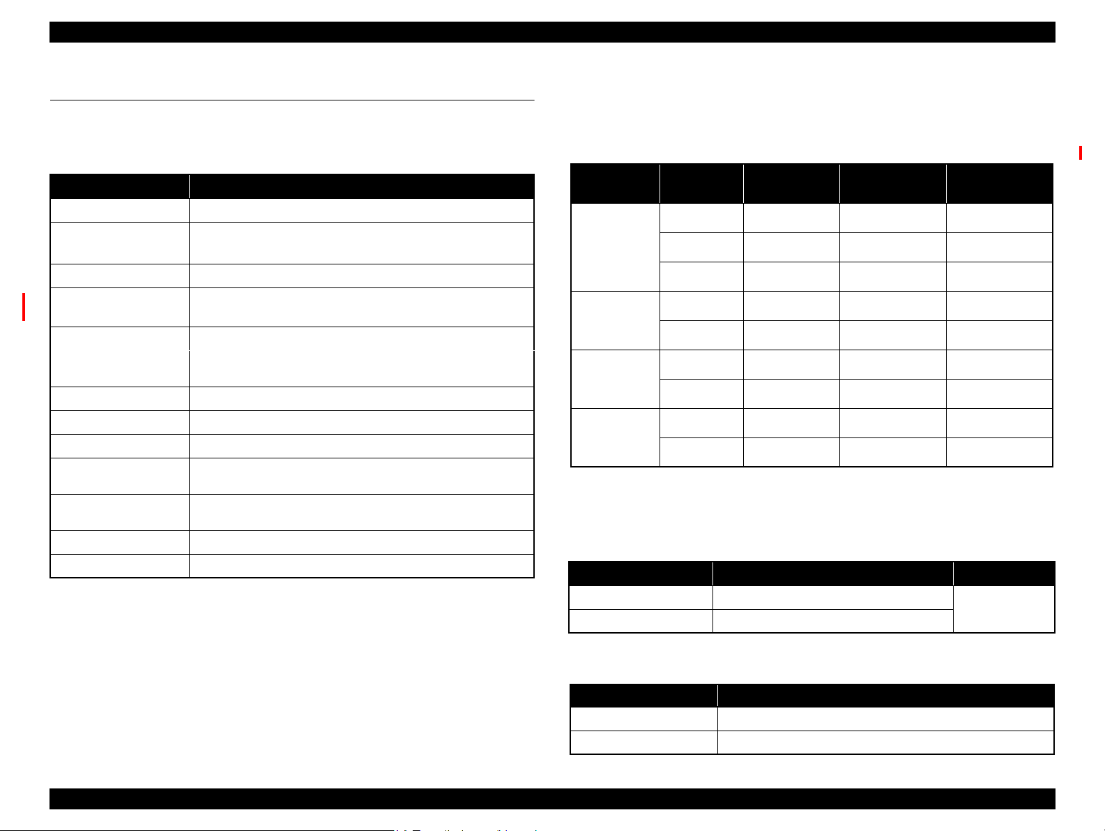
1.2 Printing Specifications
1.2.1 Basic Specifications
Table 1-2. Printer Specifications
Item Specifications
Print method On-demand inkjet
Printhead
Colors Cyan, Yellow, Magenta, Black
Print direction
Print resolution
Control code ESC/P Raster command
Input buffer size 256 KBytes
Paper feed method Friction feed
Paper feeders
Paper path
Feed speed 100 ms (25.4 mm feed)
Line pitch Programmable in units of 0.01764 mm (1/1440 inch)
Black: 360 nozzles (180 nozzles x 2 columns)
Color: 1,080 nozzles (180 nozzles x 2 columns per color)
Bi-directional minimum distance printing (logic seeking),
unidirectional printing
Horizontal x Vertical (dpi)
• 360 x 360
• 1440 x 720
• Front: 500 sheets (plain paper)
• Rear: 150 sheets (plain paper)
• Rear feed, front out
• Front feed, front out
• 720 x 720
• 5760 x 1440
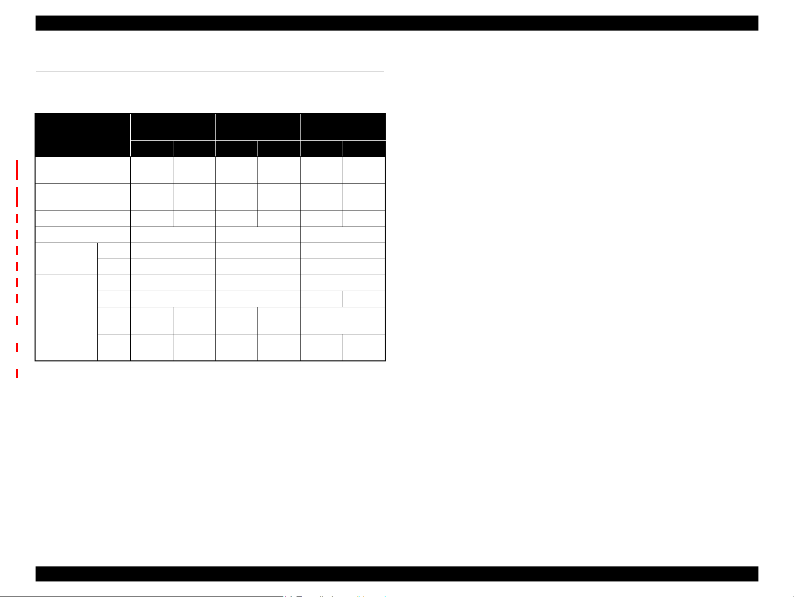
1.2.2 Ink Cartridges
The product numbers of the Epson ink cartridges for this printer are shown below.
Product No.
Table 1-3. Product No. of Ink Cartridges
Color Size
Black
Cyan
Magenta
Yellow
LL
L
M Τ6161 Τ6161
L
M Τ6162
L
M Τ6163
L
M Τ6164
B-300/B-308/
B-310N/B-318N
N/A
N/A
N/A
N/A
N/A
Shelf life
Two years from production date (if unopened), six months after opening package.
Storage Temperature
Table 1-4. Storage Temperature
Situation Storage Temperature Limit
Packed in the package
Installed on the printer
o
C to 40 oC (-4oF to 104oF)
-20
-20 oC to 40 oC (-4oF to 104oF)
B-500DN/
B-510DN
Τ6181
Τ6171
B-508DN/
B-518DN
Τ6271
Τ6261
Τ6251
Τ6172
Τ6262
Τ6162 Τ6252
Τ6173
Τ6263
Τ6163 Τ6253
Τ6174
Τ6264
Τ6164 Τ6254
1 month max.
o
at 40
C (104oF)
Dimensions
Table 1-5. Dimensions
Ink Cartridge Size Dimensions
M/L
LL
165.8 mm (W) x 106.6 mm (D) x 25.1 mm (H)
280.8 mm (W) x 106.6 mm (D) x 25.1 mm (H)
PRODUCT DESCRIPTION Printing Specifications 15
Confidential
Page 16
EPSON B-300/B-308/B-500DN/B-508DN/B-310N/B-318N/B-510DN/B-518DN Revision E
CAUTION
CAUTION
Do not use expired ink cartridge.
Ink in the cartridges freezes if the cartridges left under a
temperature of 10
o
C or lower. Once ink becomes frozen, it takes
about three hours to thaw it under a temperature of 25
moved from -20
o
C environment.)
1.2.3 Maintenance Box
Item Specifications
Model number T6190
Dimensions 86.2mm (W) x 236.9mm (D) x 56.5mm (H)
o
C to 40oC* (-4oF to 104oF)
-20
*1 month max. at 40 oC (104oF)
-20oC to 40oC* (-4oF to 104oF)
*1 month max. at 40 oC (104oF)
o
C to 60oC* (-4oF to 140oF)
-20
*Within five days at 60
Ambient temp.
Packed in the package
Installed on the printer
Transported with packed
Do not disassemble the maintenance box.
Do not touch the CSIC on the maintenance box.
Do not remove the film attached to the upper surface of the
maintenance box.
When disposing of a used maintenance box, do not tilt it before
putting it into a plastic bag.
If the maintenance box is removed and left unused for a long
time, do not reuse it.
o
C (140oF)
o
C. (when
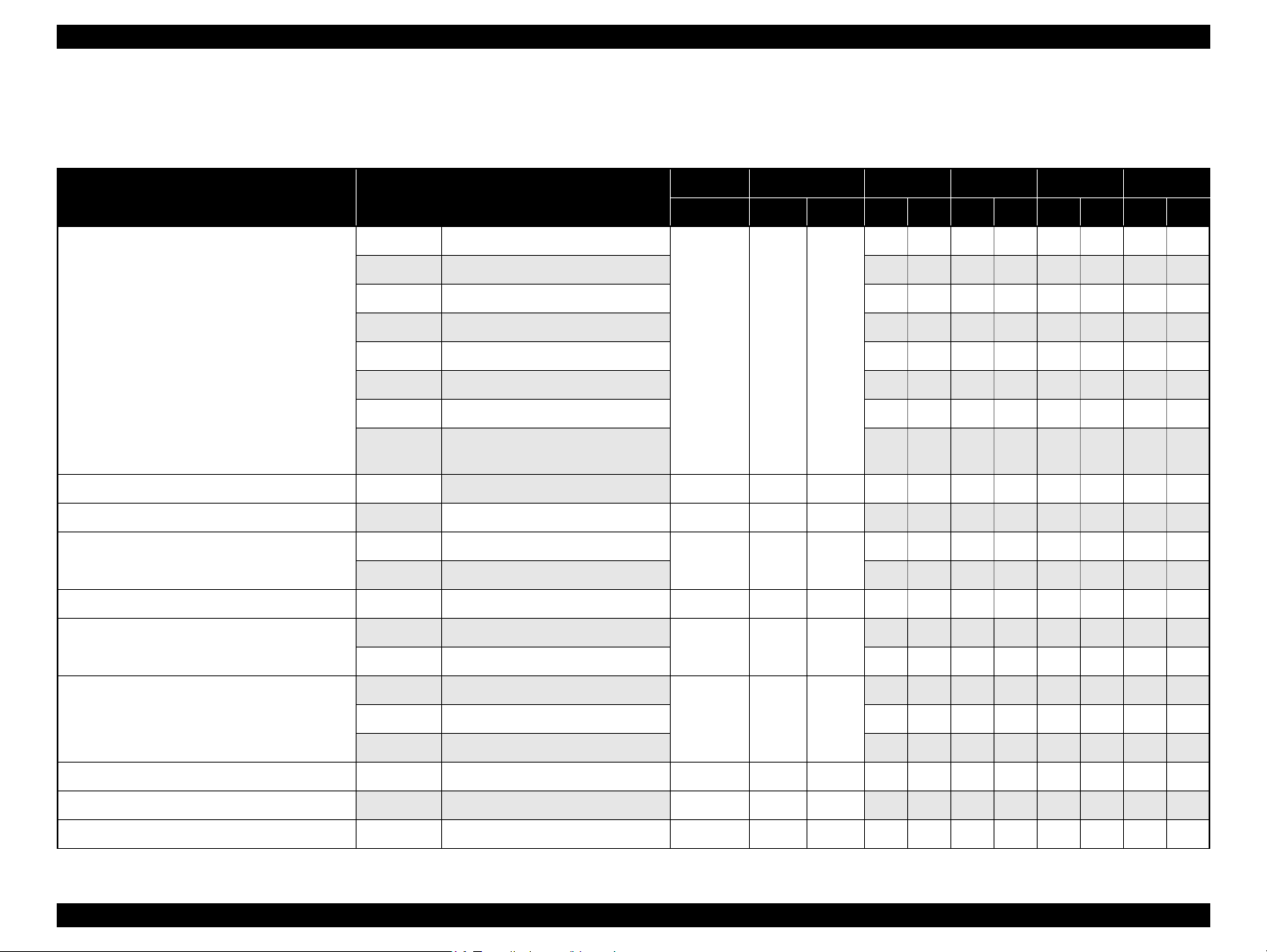
1.2.4 Print Mode
Table 1-6. Print Mode (Color/Monochrome)
Media Print Mode
• Plain paper
• Premium Bright
White Paper (EAI)
• Bright White Inkjet
Paper (Euro, Asia)
• Premium
Presentation Paper
Matte (EAI)
• Matte Paper Heavyweight (Euro, Asia)
• Presentation Paper
Matte (EAI)
• Photo Quality Inkjet
Paper (Euro, Asia)
• Envelope
• Photo Paper
• Professional Flyer
Paper
Note *1: cps = character per second
*2: B-310N/B-318N/B-510DN/B-518DN only
Draft 360x360 Eco (450cps) ON OFF
Normal 360x360 VSD-1 (360cps) ON OFF
Fine 360x360 VSD-1 (360cps) ON OFF
Photo 360x720 VSD-1 (360cps) ON OFF
Best Photo
Best Photo 1440x720 VSD-3 (200cps) ON ON
Normal 360x360 VSD-1 (360cps) OFF OFF
Photo
Best Photo 1440x1440 VSD-3 (200cps) ON ON
Best Photo 1440x1440 VSD-3 (200cps) ON ON
*2
Photo 1440x720 VSD-3 (200cps) ON ON
Photo 720x720 VSD-2 (200cps) OFF ON
*2
Photo 1440x720 VSD-3 (200cps) ON ON
Resolution
(H x V) dpi
720x720 VSD-2 (200cps) ON ON
720x720 VSD-2 (200cps) ON ON
Dot Size
(cps*1)
Bi-d
Micro
Weave
PRODUCT DESCRIPTION Printing Specifications 16
Confidential
Page 17
EPSON B-300/B-308/B-500DN/B-508DN/B-310N/B-318N/B-510DN/B-518DN Revision E
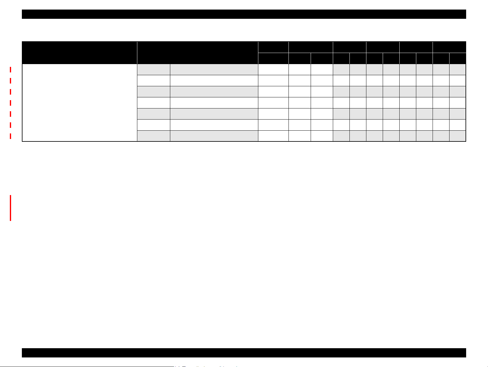
1.2.5 Supported Paper
The table below lists the paper type and sizes supported by the printer. The Supported paper type and sizes vary depending on destinations (between EAI, EUR, and Asia).
Table 1-7. Supported Paper
Paper Name Paper Size
Legal 215.9 x 355.6 mm (8.5”x14”)
Letter 215.9 x 279.4 mm (8.5”x11”) Y Y Y Y Y Y Y Y
A4 210 x 297 mm (8.3”x11.7”) YYYYYYYY
B5 182 x 257 mm (7.2”x10.1”) - - Y Y Y Y Y Y
Plain paper
Premium Bright White Paper (EAI) Letter
Bright White Inkjet Paper (Euro, Asia) A4 210 x 297 mm (8.3”x11.7”) 0.13 32.5 25 - - Y Y Y Y Y Y
Premium Presentation Paper Matte (EAI)
Matte Paper Heavy-weight (Euro, Asia)
Double-sided Matte Paper (Euro, Asia) A4 210 x 297 mm (8.3”x11.7”) 0.25 178 47 - - Y - Y - Y Y
Presentation Paper Matte (EAI)
Photo Quality Inkjet Paper (others)
A5 148 x 210 mm (5.8”x8.3”) - - Y - Y - Y Y
Half Letter 139.7 x 215.9 mm (5.5"x8.5”) Y - - - - - Y Y
A6 105 x 148 mm (4.1”x5.8”) Y - Y - Y - Y Y
User
Defined
Letter 215.9 x 279.4 mm (8.5”x11”)
A4 210 x 297 mm (8.3”x11.7”) - - Y - Y - - Y
Letter 215.9 x 279.4 mm (8.5”x11”)
A4 210 x 297 mm (8.3”x11.7”) Y - Y - Y - - Y
50.8 x 127- 216 x 1117.6 mm
100 x 148 - 216 x 297 mm
215.9 x 279.4 mm (8.5”x11”) 0.11 90 24 Y Y ----YY
*5
*6
Thickness
mm g/m
0.08-0.11 64-90 17-24
0.23 167 44
0.12 102 27
Weight EAI EUR Asia Paper Path
2
lb. P*1D*2P*1D*2P*1D*2F*3R*
Y-Y-Y- -Y
Y - Y - Y - Y Y
Y------Y
Y - - - - - - Y
4
#10 104.8 x 241.3 mm (4.125”x9.5”)
Envelopes
Photo Quality Self Adhesive Sheet A4 210 x 297 mm (8.3”x11.7”) 0.11 89 24 Y - Y - Y - - Y
Professional Flyer Paper
Photo Paper A4 210 x 297 mm (8.3”x11.7”) 0.24 190 51 Y - Y - Y - - Y
#DL 110 x 220 mm - - Y - Y - - Y
#C6 114 x 162 mm - - Y - Y - - Y
A4 210 x 297 mm (8.3”x11.7”) 0.09 90 24 Y - Y - Y - - Y
- 75-90 20-24
Y - Y - Y - - Y
PRODUCT DESCRIPTION Printing Specifications 17
Confidential
Page 18
EPSON B-300/B-308/B-500DN/B-508DN/B-310N/B-318N/B-510DN/B-518DN Revision E
Table 1-7. Supported Paper
Paper Name Paper Size
Legal 215.9 x 355.6 mm (8.5”x14”) - - - Y Y Y Y Y Y - Y
Letter 215.9 x 279.4 mm (8.5”x11”) - - - YYYYYY - Y
A4 210 x 297 mm (8.3”x11.7”) - - - Y Y Y Y Y Y - Y
Sheet with holes
*7
B5 182 x 257 mm (7.2”x10.1”) - - - - - YYYY - Y
A5 148 x 210 mm (5.8”x8.3”) - - - - - Y - Y - - Y
A6 105 x 148 mm (4.1”x5.8”) - - - Y - Y - Y - - Y
Half Letter 139.7 x 215.9 mm (5.5"x8.5”) - - - Y - - - - - - Y
Note 1: “Y” in the “P” columns indicates that the paper is supported.
2: “Y” in the “D” columns indicates that the paper is available for duplexing.
3: “Y” in the “F” columns indicates that the paper can be fed from the Front ASF.
4: “Y” in the “R” columns indicates that the paper can be fed from the Rear ASF.
5: When using the Rear ASF.
6: When using the Front ASF.
7: B-310N/B-318N/B-510DN/B-518DN only. Make sure to use the paper which does not
have a hole in the following area.
One-side printing: 26.6 mm ± 4 mm from 0-digit side of the paper
Duplex printing: 26.6 mm ± 7 mm from 0-digit side of the paper
Thickness
mm g/m
Weight EAI EUR Asia Paper Path
2
lb. P*1D*2P*1D*2P*1D*2F*3R*
4
PRODUCT DESCRIPTION Printing Specifications 18
Confidential
Page 19
EPSON B-300/B-308/B-500DN/B-508DN/B-310N/B-318N/B-510DN/B-518DN Revision E
Print Area
LM
RM
TM
BM
Cut Sheet
Paper Size
Paper Feed Direction
LM
RM
TM
BM
Print Area
Paper Feed Direction
Envelope
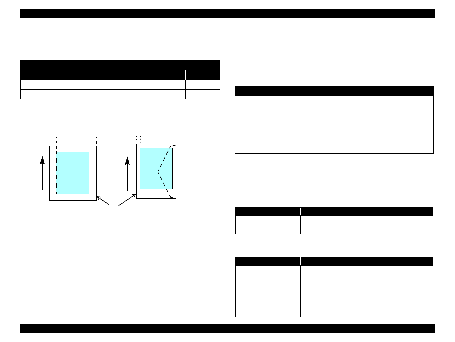
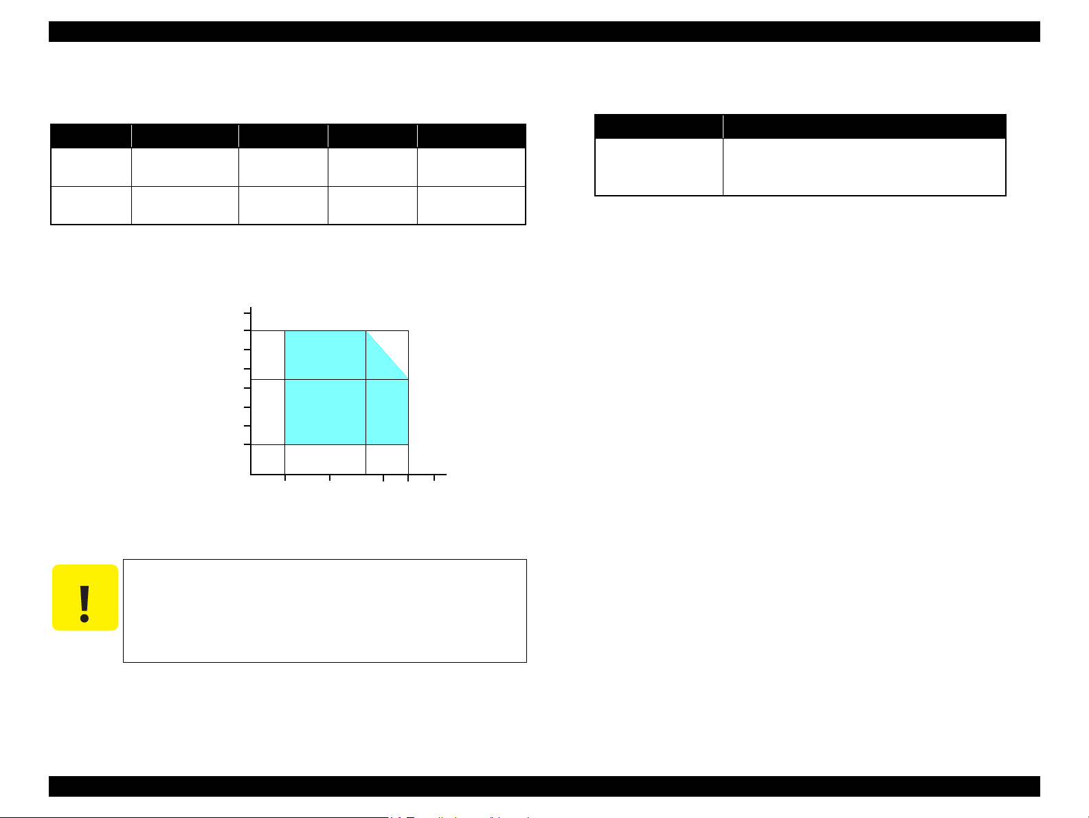
1.2.6 Printing Area
The printing area of this printer is shown below.
Table 1-8. Printing Area (Margins)
Paper Size
Any size of cut sheet
Envelope
Note* : The bottom margin becomes 16mm when duplex printing is performed using plain
paper.
Left (LM) Right (RM) Top (TM) Bottom (BM)
3 mm 3 mm 3 mm 3 mm*
5 mm 5 mm 3 mm 20 mm
Figure 1-2. Printing Area
Margin
1.3 Interface
The printer has a USB and network interfaces of the following specifications.
1.3.1 USB Interface
A USB interface is provided for connecting with a PC. The specifications are as
follows.
Table 1-9. USB Interface Specifications
Item Specifications
• Universal Serial Bus Specifications Revision 2.0
Compatible standards
Transfer rate
Data format
Compatible connector
Max. cable length
1.3.2 Network Interface (B-500DN/B-508DN/B-310N/B318N/B-510DN/B-518DN only)
B-500DN/B-508DN/B-310N/B-318N/B-510DN/B-518DN incorporates a print server.
This allows the user to use the printer via a wired LAN. The network interface
specifications are as follows.
Table 1-10. Wired LAN
Item Specifications
Communication mode 100BASE-TX/10BASE-T
Port type Selectable from Auto, MDI, and MDI-X.
• Universal Serial Bus Device Class Definition for Printing
Devices Version 1.1
480 Mbps (High Speed)
NRZIt
USB Series B
2 m or less
(B-500DN/B-508DN/B-310N/B-318N/B-510DN/B-518DN)
Table 1-11. Wired LAN Settings
10Base-T or 100Base-TX is automatically selected by the
hardware.
(B-500DN/B-508DN/B-310N/B-318N/B-510DN/B-518DN)
Setting on the printer Setting on the destination
Auto
10Base-T Half Duplex Fixed to 10Base-T and half-duplex communication mode.
10Base-T Full Duplex Fixed to 10Base-T and full-duplex communication mode.
100Base-TX Half Duplex Fixed to 100Base-TX and half-duplex communication mode.
100Base-TX Full Duplex Fixed to 100Base-TX and full-duplex communication mode.
PRODUCT DESCRIPTION Interface 19
Confidential
Page 20
EPSON B-300/B-308/B-500DN/B-508DN/B-310N/B-318N/B-510DN/B-518DN Revision E
1.4 General Specifications
1.4.1 Electrical Specifications
Table 1-12. Power Supply Specifications
Item
Rated power supply
voltage
Input voltage range
Rated current 0.7 A 0.4 A 0.7 A 0.4 A 0.7 A 0.7 A
Rated frequency 50 - 60 Hz 50 - 60 Hz 50 - 60 Hz
Input frequency
range
Power
consumption
*The values are
approximate.
50 Hz 49 - 51 Hz 49 - 51 Hz 49 - 51 Hz
60 Hz 58.8 - 61.2 Hz 58.8 - 61.2 Hz 58.8 - 61.2 Hz
Printing 30 W 32 W 30 W
Ready 6 W 8 W 6.5 W 7.0 W
Sleep
mode
Power
off
B-300/B-308 B-500DN/B-508DN
100-120V 220-240V 100-120V 220-240V 100-120V 220-240V
100-120
VAC
90-132
VAC
3 W 3.5 W 4.5 W 5 W 3.5 W
0.3 W 0.6 W 0.3 W 0.6 W 0.2 W 0.4 W
220-240
VAC
198-264
VAC
100-120
VAC
90-132
VAC
220-240
VAC
198-264
VAC
B-310N/B-318N/
B-510DN/B-518DN
100-120
VAC
90-132
VAC
220-240
VAC
198-264
VAC
1.4.2 Safety Approvals (Safety standards/EMI)
Taiwan CNS13438 Class B
CNS14336
EU EN55022 Class B
EN55024
EN61000-3-2, EN61000-3-3
EU/ Germany EN60950-1
Russia GOST-R (IEC60950-1, CISPR 22)
Singapore IEC60950-1
Korea K60950-1
KN22 Class B
K61000-4-2/-3/-4/-5/-6/-11
Note 1: B-300/B-308/B-310N/B-318N/B-510DN/B-518DN conform to Energy Star.
2: When the printer is not operated for more than three minutes, the printer goes into the
power save mode within five minutes.
PRODUCT DESCRIPTION General Specifications 20
Confidential
Page 21
EPSON B-300/B-308/B-500DN/B-508DN/B-310N/B-318N/B-510DN/B-518DN Revision E
CAUTION
10
27
30
35
40
20
Temperature (oC)
20
30
40
50
80
70
60
Humidity (%)
90
1.4.3 Environmental Conditions
Table 1-13. Environmental Conditions
Condition Temperature*
Operating
Unpacked
10 to 35
(50 to 95oF)
-20 to 40
(-4 to 104oF)
1
Humidity*
o
C
o
3
C*
20 to 80%
5 to 85%
Note *1: The combined Temperature and Humidity conditions must be within the blue-shaded
range in Figure 1-3.
*2: No condensation
*3: Must be less than 1 month at 40
o
C.
1,2
(1 msec or less)
(2 msec or less)
Shock Vibration
1G
2G
0.15G (10 to 55Hz)
0.50G (10 to 55Hz)
1.4.4 Durability
Item Specifications
Printer mechanism life
Until any one of the following conditions is met.
• 100,000 sheets
• Five years
Figure 1-3. Temperature/Humidity Range
When not using the printer, make sure the Printhead is covered
with the cap and the ink cartridge is installed.
If the Printhead is not covered with the cap when the printer is
off, turn on the printer with the ink cartridge installed, make
sure the Printhead is covered with the cap, and then turn the
printer off.
PRODUCT DESCRIPTION General Specifications 21
Confidential
Page 22
EPSON B-300/B-308/B-500DN/B-508DN/B-310N/B-318N/B-510DN/B-518DN Revision E
Power button
OK button, Arrow buttons
Cancel button
LCD
Power LED
Ink LED
Paper LED
Power button
Paper button
Ink button
Power LED
Ink LED
Paper LED
Ink LEDs
(Black, Cyan, Magenta, Yellow)
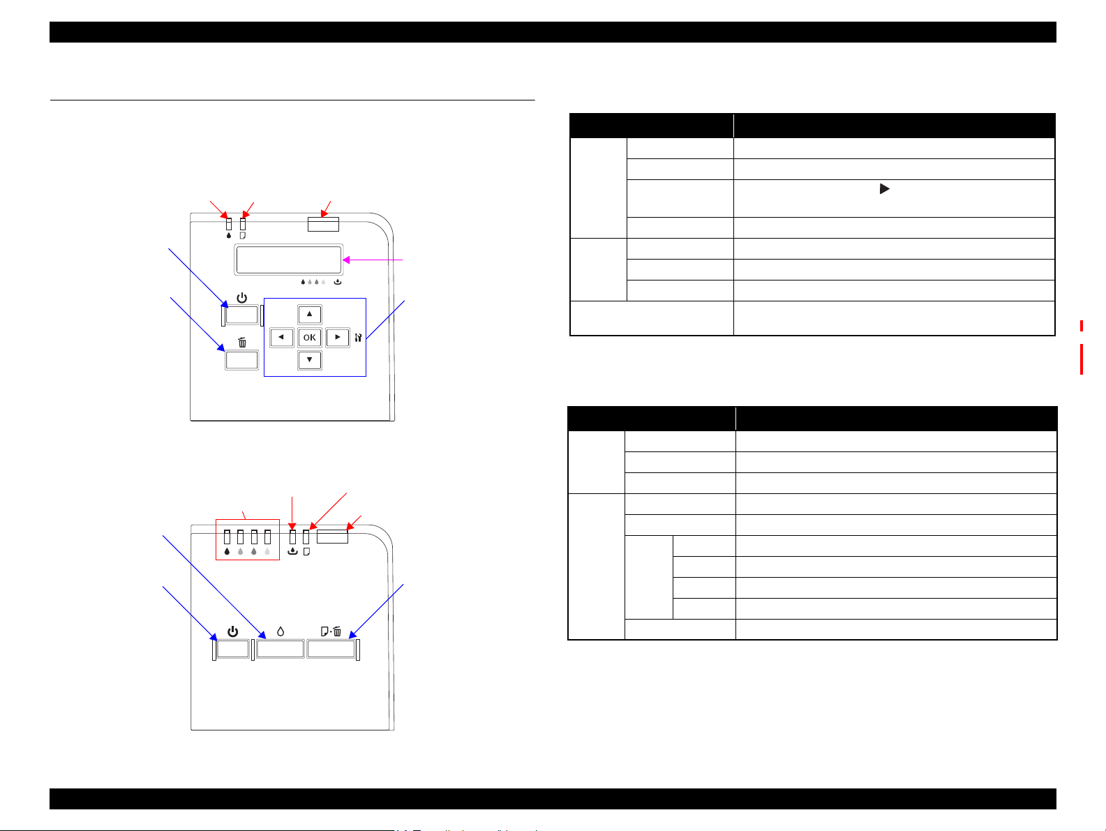
1.5 Control Panel
1.5.1 Operation Buttons
The operation buttons, LEDs, and LCD (B-500DN/B-508DN/B-310N/B-318N/B510DN/B-518DN only) are shown below.
Figure 1-4. Control Panel
(B-500DN/B-508DN/B-310N/B-318N/B-510DN/B-518DN)
Table 1-14. Operation Buttons, LED, LCD
(B-500DN/B-508DN/B-310N/B-318N/B-510DN/B-518DN)
Buttons/LEDs/LCD Function
Power Turns the power ON/OFF.
OK Clears an error and accepts a selected menu setting.
Button
LED
LCD
Arrows
Cancel Cancels the menu selection, or cancels a job.
Power Indicates the power-on status, or operating status.
*1
Ink Indicates an error status regarding to ink and maintenance box.
Paper Indicates an error status regarding to paper.
*1
• Displays the menu screen. ( button)
• Goes to the next item in the menu.
Indicates the printer status, error, and menu screen.
Indicates fatal error code
*2
Note *1: See Table 1-16 for more details about the LEDs and LCD.
*2: B-310N/B-318N/B-510DN/B-518DN only
Table 1-15. Operation buttons, LED (B-300/B-308)
Operation buttons/LEDs Function
Power Turns the power ON/OFF.
Button
LED
Note * : See Table 1-16 for more details about LEDs.
Ink Runs a cleaning.
Paper Feeds / ejects paper
Power Indicates the power-on status, or operating status.
Ink Indicates an error status regarding to ink and maintenance box.
Black Indicates an error status of black ink.
*
Ink
Paper Indicates an error status of paper.
Cyan Indicates an error status of cyan ink.
Magenta Indicates an error status of magenta ink.
Yellow Indicates an error status of yellow ink.
Figure 1-5. Control Panel (B-300/B-308)
PRODUCT DESCRIPTION Control Panel 22
Confidential
Page 23

EPSON B-300/B-308/B-500DN/B-508DN/B-310N/B-318N/B-510DN/B-518DN Revision E
1.5.2 LEDs and LCD Indications
Table 1-16. LEDs and LCD Indications
Status
Powering ON
Printing is available
Powering ON
Switching monochrome priority mode on/off
*3
*3
*4
*3
Maintenance call --- --- --Ink level low --Maintenance box near full --Processing data
Feeding / ejecting paper
Executing ink sequence
Printer cover open error ---
Power LED Ink LED Paper LED Ink LEDs*
Flash
--- --- --- PLEASE WAIT --- ---
ON --- --- --- READY --- 22
*
5
Flash / ON
OFF
--- --- --- PLEASE WAIT 21 ---
Flash at high speed Flash at high speed 2
Flash
Flash
Flash
Flash
Flash
Flash
--- --- --- --- 17 17
--- --- --- --- 16 16
--- --- --- --- 15 15
Flash
2
---
Flash
--- --- REPLACE MAINT ICON 18 18
Flash
2 --- CLOSE PRINTER COVER 14 14
Paper out error --- --- ON ---
LEDs
No duplex unit error --- ---
Flash
2 --- SET DUPLEX UNIT 12 12
1
LCD Message*
--- --- --- 21
2 NOZZLE MAINT ERROR SEE GUIDE 20 20
6
*
REPLACE INK CARTRIDGE ICON 19 19
(Front) SET PAPER IN CASSETTE OK
(Rear) SET PAPER IN AUTO FEEDER OK
2
B-300/B-308/
B-500DN/B-510DN
Multi-feed error --- --- ON --- DOUBLE FEED JAM REMOVE PAPER OK 11 11
Ink cartridge CSIC error --- ON --- ON*
No ink cartridge or no ink error --- ON --- ON*
6
REPLACE INK CARTRIDGE ICON
6
SET INK CARTRIDGE ICON
Maintenance cartridge CSIC error --- ON --- --- SET MAINT BOX ICON
No maintenance cartridge or no ink error --- ON --- --- SET MAINT BOX ICON
Ink lock lever open error --- ON --- ---
Maintenance box cover open error --- ON --- ---
Paper jam --- ---
Flash
---
MOVE INK LEVER DOWN ICON
SET INK CARTRIDGE
CLOSE MAINT BOX COVER ICON
SET MAINT BOX
(Front) REMOVE JAMMED PAPER OK
(Rear) REMOVE JAMMED PAPER OK
*8
*9
ICON
ICON
*7
*7
*7
*7
*7
*7
*7
*7
(Duplex) DUPLEX UNIT JAM REMOVE PAPER OK
Fatal error OFF
Flash at high speed Flash at high speed
---
PRINTER ERROR RESTART PRINTER
*10
XXXX
Service call OFF Alternate Flash 2 Alternate Flash 1 --- SERVICE CALL SEE GUIDE 2 2
Power OFF
Reset request*
11
Note *1: B-300/B-308 only
*2: B-500DN/B-508DN/B-310N/B-318N/B-510DN/B-518DN only
*3: B-310N/B-318N/B-510DN/B-518DN only
*4: B-300/B-308/B-500DN/B-508DN only
*5: B-300/B-308 power LED flashes, and that of B-500DN/B-508DN turns ON.
*6: The corresponding LED flashes or lights.
*7: See “Table 1-17. LCD Icon Display (B-500DN/B-508DN/B-310N/B-318N/B-510DN/B-518DN only)” on
page24 for the icons shape.
Flash at high speed
ON*4 /
Flash
*
3
OFF OFF OFF POWER OFF 1 1
ON*4/ --- *
3
ON*4/ --- *
3
ON --- --- ---
Note : ---: No change
Flash: Repeats ON for 1.25 seconds, OFF for 1.25 seconds
Flash 2: Repeats ON for 0.5 second, OFF for 0.5 second, ON for 0.5 second
Flash at high speed: Repeats ON for 0.5 second, OFF for 0.5 second
Flash at high speed 2: Repeats OFF for 0.5 second, ON for 0.5 second
Alternate Flash1: Same as the above Flash.
Alternate Flash1: Repeats OFF for 1.25 seconds, ON for 1.25 seconds
and OFF for 1.0 second.
*8: B-500DN/B-508DN only. The LED turns ON when the ink lever is moved to its upper position after an error occurs.
*9: The LED turns ON when the maintenance cover is opened after an error occurs.
*10: The fatal error code is indicated only for B-310N/B-318N/B-510DN/B-518DN. See “ 3.3.2 Fatal Error” on
page48 for the details.
*11: When a reset request occurs, the LED lights for 0.2 seconds.
Priority
B-310N/B-318N/
B-510DN/B-518DN
13 13
10 10
99
88
77
66
55
44
33
PRODUCT DESCRIPTION Control Panel 23
Confidential
Page 24
EPSON B-300/B-308/B-500DN/B-508DN/B-310N/B-318N/B-510DN/B-518DN Revision E
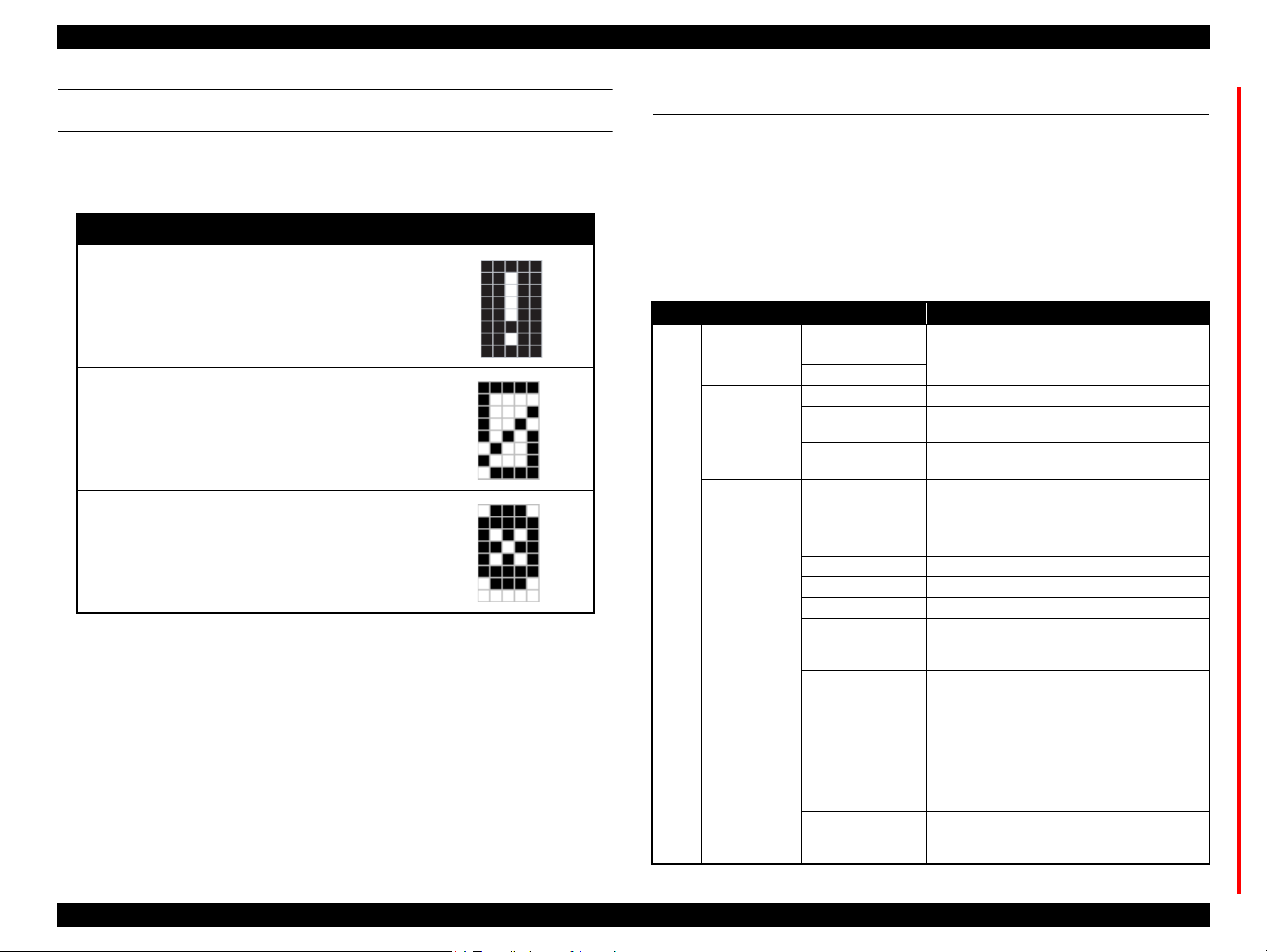
LCD ICON DISPLAY
(B-500DN/B-508DN/B-310N/B-318N/B-510DN/B-518DN)
The following icons appear on the LCD according to the printer status.
Table 1-17. LCD Icon Display
(B-500DN/B-508DN/B-310N/B-318N/B-510DN/B-518DN only)
Printer Status Icon
• Ink level low
• Maintenance box near full
• No ink
• Maintenance box full
• Ink cartridge CSIC error
• No ink cartridge
1.6 Various Settings
1.6.1 Panel Operation
1.6.1.1 Menu Configuration (B-500DN/B-508DN/B-310N/B-318N/ B-510DN/B-518DN only)
The setting screen is displayed by pressing the right arrow button on ready mode (the
LCD display is “READY” or “POWER SAVE”). The following explains the menu
structure and the outline of the menu functions.
Table 1-18. Menu Configuration
Menu Description
LANGUAGE Selects the language displayed on the LCD.
USB
Network
NOZZLE CHECK Prints a printhead nozzle check pattern.
STATUS SHEET
NETWORK SHEET
VERSION Displays the firmware version.
MAINTENANCE
BOX
HEAD ALIGNMENT Adjusts the printhead alignment.
CLEANING Runs a printhead cleaning.
CLEANING SHEET Runs a cleaning for the rollers inside the printer.
CONTRAST ADJ. Adjusts the contrast of the LCD.
AUTO CLEANING
LOW SPEED MODE
NETWORK SETUP Selects the method to configure the network settings.
PASSWORD SET.
LOCK SETTING
Selects the printer control language for the port.
Prints a status sheet for current printer status. (See
Figure 1-8
Prints a network status sheet for current settings of the
network interface. (See Figure 1-9 and Figure 1-10
Displays the rough estimate of the remaining
capacity of the Maintenance Box.
Changes the setting of the AID detection cleaning.
(See “1.6.2.1 AID Detection Cleaning (B-310N/B-
318N/B-510DN/B-518DN only)” on page26.)
Changes the setting of the low speed mode (MPBF
priority mode). (See “1.6.3 Low Speed Mode (MPBF
Priority Mode) (B-310N/B-318N/B-510DN/B518DN only)” on page28.)
Sets a password.
(See “ Password setting” on page26.)
Changes the setting of the panel operation lock. (See
“1.6.1.2 Panel Operation Lock Setting (B-310N/B318N/B-510DN/B-518DN only)” on page25.)
.)
.)
MENU
PRINTER
SETTING
TEST PRINT
PRINTER
STATUS
MAINTENANCE
NETWORK
SETTING
PASSWORD
*
MENU
Note* : B-310N/B-318N/B-510DN/B-518DN only.
PRODUCT DESCRIPTION Various Settings 24
Confidential
Page 25
EPSON B-300/B-308/B-500DN/B-508DN/B-310N/B-318N/B-510DN/B-518DN Revision E
CAUTION
1.6.1.2 Panel Operation Lock Setting (B-310N/B-318N/B-510DN/B-518DN only)
For B-310N/B-318N/B-510DN/B-518DN, the panel operation can be locked after
setting the password. (See Password setting (p.26).)
Table 1-19. Panel Operation Lock Setting
ON OFF
On ready mode (the LCD display is
“READY” or “POWER SAVE”), the
password is required to go to the setting
screen.
If the correct password is entered, goes to
the setting screen.
“WRONG PASSWORD” is displayed if a
wrong password is entered, and the access
to the setting screen is denied. After the
error is displayed for a while, the printer
returns to the ready mode (the LCD
display is “READY”).
Error reset and powering off are still
available.
Note : The lock/unlock condition is not printed on the printed sheets such as the nozzle check
pattern or the status sheets.
Setting Method
1. Perform Password setting (p.26) by operating the control panel.
2. Select “LOCK SETTING” from “MENU” (Table 1-18), and select “ON” or
“OFF”.
Entering the password is not required to go to
the setting screen even the password is
registered.
Resetting the Password/Unlocking the Panel Operation Lock
If you need to reset the password or unlock the panel operation because of
forgetting the password and such, follow the steps below to reset them.
Do not disclose the following method to the end users.
Resetting/Unlocking method
1. Press and hold the right arrow button, left arrow button and OK button and
then turn on the printer.
2. Release all the buttons after the printer is turned on.
Settings after reset
• Password: Not set
• Panel operation lock: OFF
Note 1: If the cancel button is pressed during its setting or when “ON” is set, the printer
returns to the ready mode (the LCD display is “READY” or “POWER SAVE”).
2: After “ON” is set, the panel operation is locked immediately.
3: When “OFF” is set, the display returns to “PASSWORD MENU”.
4: Once the password is set, the panel operation can be locked by performing Step 2.
PRODUCT DESCRIPTION Various Settings 25
Confidential
Page 26
EPSON B-300/B-308/B-500DN/B-508DN/B-310N/B-318N/B-510DN/B-518DN Revision E
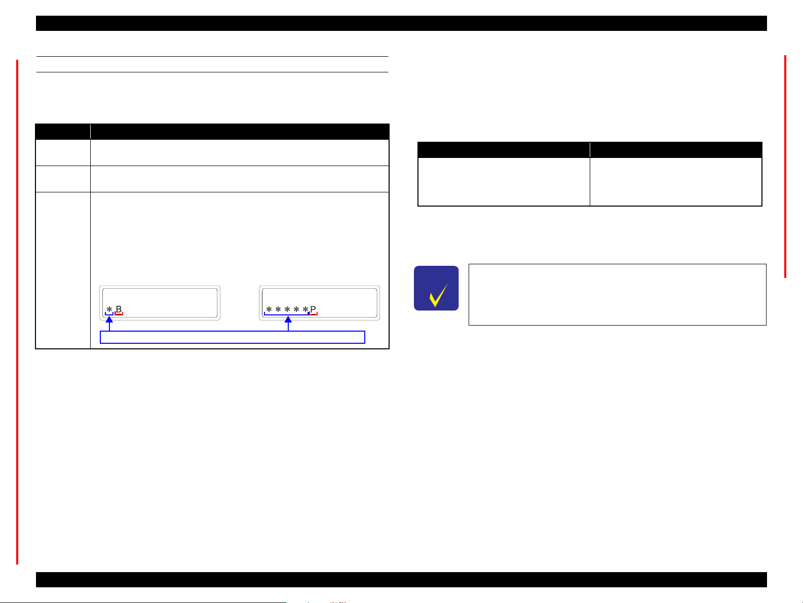
NEW PASSWORD NEW PASSWORD
An input character changes to “* (asterisk)” each time it is accepted.
PASSWORD SETTING
Select the “PASSWORD SET.” from the “MENU” (Table 1-18) to set or change
the password.
Table 1-20. Password Setting
Item Description
Digit of the
password
Available
characters
Method
Within 1 to 8
Space,!”#$%&'()*+,-./, 0 to 9, ;:<=>?@, A to Z, [\]^_`, a to z, {|}~
Select the characters with the up and down arrow buttons, and move to the next
digit with the right arrow button. When pressing the right arrow button, the input
character is masked with “* (asterisk)”. The characters which are masked with “*
(asterisk)” will be saved on the EEPROM as the password after pressing the OK
button. To set the password, entries are required three time according to the
instruction displayed on the LCD (“CURRENT PASSWORD”, “NEW
PASSWORD” and “REENTER NEW PASSWORD”).
1.6.2 AID Function Setting
1.6.2.1 AID Detection Cleaning (B-310N/B-318N/B-510DN/B-518DN only)
For B-310N/B-318N/B-510DN/B-518DN, the AID detection cleaning can be set on/off.
Table 1-21. AID Detection Cleaning
ON OFF
Automatically checks the printhead nozzles
with AID function and carries out printhead
cleaning if they are clogged.
Setting Method
Select “AUTO CLEANING” from “MENU” (Table 1-18), and select “ON” or
“OFF”.
CHECK
POINT
This setting is not available for B-300/B-308/B-500DN/B-508DN.
The nozzle check with the AID function and
auto cleaning is not carried out. Carries out
the printhead cleaning only when selecting
“CLEANING” from “MENU” (Table 1-18).
Note 1: The password is not set when shipping from the factory.
2: If there is a wrong entry to “CURRENT PASSWORD” or “REENTER NEW
PASSWORD”, “WRONG PASSWORD” is displayed and then returned to the
“PASSWORD MENU” screen.
3: After the password is entered in “REENTER NEW PASSWORD”, the change is
completed and the display returns to “PASSWORD MENU”.
4: The password is stored on the EEPROM (not NMI area), and kept even the power is off.
1.6.1.3 Forced Power OFF
For B-300/B-308/B-500DN/B-508DN/B-310N/B-318N/B-510DN/B-518DN, the
power can be turned off forcibly by the following panel operation. If the power is
turned off forcibly, the same process of the normal power-off is executed.
Operation Method
1. Press and hold the power button and the OK button for seven seconds or
more.
2. Release the power button after the printer is turned off.
PRODUCT DESCRIPTION Various Settings 26
Confidential
Page 27
EPSON B-300/B-308/B-500DN/B-508DN/B-310N/B-318N/B-510DN/B-518DN Revision E
CHECK
POINT
VERSION VERSION
AID high quality mode
Dot missing tolerance mode
* (asterisk)
is indicated
CHECK
POINT
xxxxxxxxxxxxxx* xxxxxxxxxxxxxx
* (asterisk) is printed
Monochrome priority mode is on
Monochrome priority mode is off
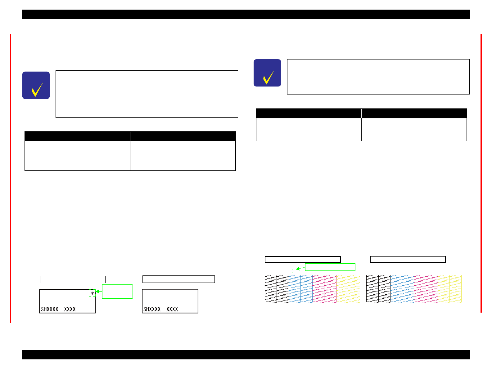
1.6.2.2 AID High Quality Mode/Dot Missing Tolerance Mode
For B-310N/B-318N/B-510DN/B-518DN, the AID high quality mode or the dot
missing tolerance mode can be selected by the special operation at power-on when the
AID detection cleaning is on.
For B-300/B-308/B-500DN/B-508DN, this setting is available only
when the firmware is the following version or later. However, the
setting mode is fixed to “dot missing tolerance mode” for B-300/B-
308.
• B-300/B-308: SH1998
• B-500DN/B-508DN: SL1998
Table 1-22. Mode
AID High Quality Mode Dot Missing Tolerance Mode
Checks the nozzle clogging and carries out
appropriate cleaning.
Setting Change Method
Follow the procedure below to switch the cleaning mode between the AID high
quality mode and dot missing tolerance mode.
1. Press and hold the power button and the OK button simultaneously when the
power is off.
2. Release the all buttons when the power is turned on.
How to Check the Current Mode
Select “VERSION” from “MENU” (see Table 1-18), and check the upper right
corner of the LCD. If “*(asterisk)” is displayed, the printer is the AID high quality
mode. The mode status cannot be confirmed from the printed sheets such as the
nozzle check pattern or the status sheets.
If two or less nozzles and no neighboring
nozzles are clogged, the cleaning is not
carried out. For nozzle clogging detection in
the other cases, the cleaning is carried out.
1.6.2.3 Monochrome Priority Mode
For B-310N/B-318N/B-510DN/B-518DN, “monochrome priority mode” with the AID
function is available to check the nozzle clogging only for nozzles of black ink.
This setting is available when the firmware is the following version
or later for B-300/B-308/B-500DN/B-508DN.
• B-300/B-308: SH1998
• B-500DN/B-508DN: SL1998
Table 1-23. Monochrome Priority Mode
Valid Invalid
Checks the nozzle clogging only for nozzles
of black ink, and carries out printhead
cleaning.
Note : The monochrome priority mode is invalid as the default.
Setting Method
Follow the procedure below to switch between valid and invalid.
1. Press and hold the power button and the up arrow button simultaneously.
2.
After the power LED flashes,
button, and press and hold the down arrow button immediately.
3. When the ink LED and the paper LED starts flashing alternately, release the
down arrow button.
How to Check the Current Mode
When the monochrome priority mode is on, “* (asterisk)” is printed on the nozzle
check pattern as shown below. The mode status (valid or invalid) cannot be
confirmed on the LCD.
Checks all the nozzles and carries out
printhead cleaning.
release the
power button and the up arrow
Figure 1-6. How to Check AID High Quality Mode/Dot Missing Tolerance Mode
PRODUCT DESCRIPTION Various Settings 27
Figure 1-7. How to Check Monochrome Priority Mode
Confidential
Page 28

EPSON B-300/B-308/B-500DN/B-508DN/B-310N/B-318N/B-510DN/B-518DN Revision E
1.6.3 Low Speed Mode (MPBF Priority Mode) (B-310N/B-318N/B-510DN/B-518DN only)
To prevent the troubles (printhead clogging or the like) from occurring due to paper dust
caused by the printing-related movement, the low speed mode (MPBF priority mode) is
available for
The carriage always moves from end to end
(full-digit drive) for printing. It can decrease
paper dust caused by the printing-related
movement to prevent printing troubles such as
printhead clogging. However, the printing
speed becomes slower.
Note : The low speed mode is off as the default.
Setting Method
Set by panel operation
Note : The setting is stored in the non-volatile memory and kept when the power is off.
Automatic change
B-310N/B-318N/B-510DN/B-518DN
.
Table 1-24. Low Speed Mode (MPBF Priority Mode)
ON OFF
Carries out the normal printing.
Select “LOW SPEED MODE” from “MENU” (Table 1-18), and select “ON”
or “OFF”.
If all the following conditions are met, the low speed mode (MPBF priority
mode) is turned on even if the setting from the panel is off.
• Stays in ready mode for five to seven minutes.
• More than 100 sheets are printed after the last AID detection.
• Number of accumulated printed sheets is 10 to 400 after the last manual
cleaning.
Note1: When the setting is on by the automatic change, the setting is turned off when the
ink cartridge cover is opened/closed.
1.7 Status Sheet
B-500DN/B-508DN/B-310N/B-318N/B-510DN/B-518DN prints the following printer
status sheet when the Printer Status menu is selected. For B-300/B-308, turn it on while
holding down the Ink button. B-500DN/B-508DN/B-310N/B-318N/B-510DN/B518DN also can print a network status sheet shown on the following pages.
Log Status Sheet
Printer Name "model name"
Serial No. xxxxxxxxxxx
Firmware version SHxxxx(SLxxxx)
First Print Time yyyy/mm/dd hh:mm
Last Print Time yyyy/mm/dd hh:mm
Total Pages 000000
Color Pages 000000
B/W Pages 000000
Print of papers
Total Mono Color
Simplex Duplex Simplex Duplex
A4/Letter 000000 000000 000000 000000 000000
A5 000000 000000 000000 000000 000000
A6/HAGAKI 000000 000000 000000 000000 000000
Envelope 000000 000000 000000 000000 000000
Others 000000 000000 000000 000000 000000
Print of mode[pages]
Simplex Duplex Total
Mono 000000 000000 000000
Color 000000 000000 000000
Total 000000 000000 000000
2: The setting made by the automatic change is not saved in the non-volatile memory,
therefore, the setting is turned off once the power is off.
Figure 1-8. Printer Status Sheet Sample
PRODUCT DESCRIPTION Status Sheet 28
Confidential
Page 29

EPSON B-300/B-308/B-500DN/B-508DN/B-310N/B-318N/B-510DN/B-518DN Revision E
HHHHHHHHHHHHHHHHHHHHHHHHHHHHHHHHHHHHHH
HH EPSON Network Status Sheet (1/2) HH
HHHHHHHHHHHHHHHHHHHHHHHHHHHHHHHHHHHHHH
<General Information>
Card Type EPSON Built-in 10Base-T/100Base-TX Print Server
SerialNumber XXXXXXXXXXXX
MAC Address XX:XX:XX:XX:XX:XX
Hardware XX.XX
Software XX.XX
Printer Model XXXXXXXX
Time YYYY-MM-DD HH:MM:SS GMT+/-HH:MM
<Ethernet>
Network Status Auto(10BASE-T/100BASE-TX, Half/Full Duplex)/
10BASE-T/100BASE-TX, Half/Full Duplex
Port Type Auto/MDI/MDI-X
<TCP/IP>
Get IP Address Auto/Manual
IP Address XXX.XXX.XXX.XXX
Subnet Mask XXX.XXX.XXX.XXX
Default Gateway XXX.XXX.XXX.XXX
APIPA Enable/Disable
Set using PING Enable/Disable
Acquisition way of DNS ADDR Enable/Disable
DNS Server Address XXX.XXX.XXX.XXX
XXX.XXX.XXX.XXX
XXX.XXX.XXX.XXX
Acquire Host/Domain name Enable/Disable
Host Name XXXXXXXX
Domain Name XXXXXXXX
Register the NW I/F to DNS Enable/Disable
Register directly to DNS Enable/Disable
Universal Plug and Play Enable/Disable
Device Name XXXXXXXX
Bonjour Enable/Disable
Bonjour Name XXXXXXXX.local.
Bonjour Printer Name XXXXXXXX
Bonjour Service XXXXXXXX._printer._tcp.local.
XXXXXXXX._http._tcp.local.
<Printing Control>
Printing Control Enable/Disable
Access Control Allow/Deny
Access Control List 1 XXX.XXX.XXX.XXX - XXX.XXX.XXX.XXX
Access Control List 2 XXX.XXX.XXX.XXX - XXX.XXX.XXX.XXX
Access Control List 3 XXX.XXX.XXX.XXX - XXX.XXX.XXX.XXX
Access Control List 4 XXX.XXX.XXX.XXX - XXX.XXX.XXX.XXX
Access Control List 5 XXX.XXX.XXX.XXX - XXX.XXX.XXX.XXX
Access Control List 6 XXX.XXX.XXX.XXX - XXX.XXX.XXX.XXX
Access Control List 7 XXX.XXX.XXX.XXX - XXX.XXX.XXX.XXX
Access Control List 8 XXX.XXX.XXX.XXX - XXX.XXX.XXX.XXX
Access Control List 9 XXX.XXX.XXX.XXX - XXX.XXX.XXX.XXX
Access Control List 10 XXX.XXX.XXX.XXX - XXX.XXX.XXX.XXX
Access Control List 11 XXX.XXX.XXX.XXX - XXX.XXX.XXX.XXX
Access Control List 12 XXX.XXX.XXX.XXX - XXX.XXX.XXX.XXX
Access Control List 13 XXX.XXX.XXX.XXX - XXX.XXX.XXX.XXX
Access Control List 14 XXX.XXX.XXX.XXX - XXX.XXX.XXX.XXX
Access Control List 15 XXX.XXX.XXX.XXX - XXX.XXX.XXX.XXX
Access Control List 16 XXX.XXX.XXX.XXX - XXX.XXX.XXX.XXX
HHHHHHHHHHHHHHHHHHHHHHHHHHHHH Printer Model Name HH
HHHHHHHHHHHHHHHHHHHHHHHHHHHHHHHHHHHHHH
HH EPSON Network Status Sheet (2/2) HH
HHHHHHHHHHHHHHHHHHHHHHHHHHHHHHHHHHHHHH
<IPP>
IPP URL http://xxx.xxx.xxx.xxx
Printer Name XXXX
<Port Control>
LPR Enable/Disable
Port9100 Enable/Disable
Port2501 Enable/Disable
FTP Enable/Disable
IPP Enable/Disable
<SNMP>
Read Community public
IP Trap 1 Enable/Disable
IP Trap Address 1 XXX.XXX.XXX.XXX
IP Trap Community 1 XXXXXXXX
IP Trap Port 1 XXXX
IP Trap 2 Enable/Disable
IP Trap Address 2 XXX.XXX.XXX.XXX
IP Trap Community 2 XXXXXXXX
IP Trap Port 2 XXXX
IP Trap 3 Enable/Disable
IP Trap Address 3 XXX.XXX.XXX.XXX
IP Trap Community 3 XXXXXXXX
IP Trap Port 3 XXXX
IP Trap 4 Enable/Disable
IP Trap Address 4 XXX.XXX.XXX.XXX
IP Trap Community 4 XXXXXXXX
IP Trap Port 4 XXXX
<Time>
Time Server Enable/Disable
Time Server Address XXX.XXX.XXX.XXX
Synchronize Interval XX
Time Difference(GMT+/-HH:MM) +/-HH:MM
Time Server Status Success/Failure/Synchronize/Invalid
<Idle Timeout>
LPR XXXX sec
Port9100 XXXX sec
IPP xxxx sec
<Software Information>
Network FW XX.XX XXXXX
EPSONNet Config Web XX.XX XXXXX
HHHHHHHHHHHHHHHHHHHHHHHHHHHHH Printer Model Name HH
PRODUCT DESCRIPTION Status Sheet 29
Figure 1-9. Network Status Sheet Sample (1) Figure 1-10. Network Status Sheet Sample (2)
Confidential
Page 30

OPERATING PRINCIPLES
CHAPTER
2
Confidential
Page 31

EPSON B-300/B-308/B-500DN/B-508DN/B-310N/B-318N/B-510DN/B-518DN Revision E
(4) Front ASF
Retard Home
Sensor
PF Encoder
Rear ASF
PW Sensor
CR Encoder
Cover Open Sensor
PF Roller
EJ Roller
Carriage Assy
Printhead
EJ Frame
EJC Sensor
Ink System
APG Phase Sensor
APG Unit
ASF Sub Encoder
ASF Sub Motor
ASF Motor
(1) Rear ASF Phase
Sensor
(3) Duplex Unit
Sensor
(1)
(2)
(3)
(4)
(2) Rear ASF Home
Sensor
CR Motor
ASF Encoder
PE Sensor
CR Shaft
(a) Front ASF
Front Paper Sensor
(b) Front ASF
Paper End Sensor
(a) (b)
Ink Cartridge Lock
Cover Sensor
PF Scale
CR Scale
CR Timing Belt
PF Motor
ASF Scale
ASF Sub Scale
PF Timing Belt
A#180
A#179
A#178
A#3
A#2
A#1
B#180
B#179
B#178
B#3
B#2
B#1
D#180
D#179
D#178
D#3
D#2
D#1
F#180
F#179
F#178
F#3
F#2
F#1
C#180
C#179
C#178
C#3
C#2
C#1
E#180
E#179
E#178
E#3
E#2
E#1
H#180
H#179
H#178
H#3
H#2
H#1
G#180
G#179
G#178
G#3
G#2
G#1
Carriage movement direction
Paper feed direction
2.1 Overview
This chapter describes the operating principles of B-300/B-308/B-500DN/B-508DN/
B-310N/B-318N/B-510DN/B-518DN printer mechanism and electric circuits.
2.1.1 Printer Mechanism
The general diagram of the printer mechanism is shown below.
Operating Principles Overview 31
Figure 2-1. Printer Mechanism Block Diagram
2.1.2 Printhead
Print method: On-demand inkjet
(F8-Mach Turbo 2)
Nozzle configuration
Color Bk, C, M, Y (4 colors)
Number of nozzles 1,440 nozzles (180 nozzles x 2 per color)
Nozzle pitch 0.282mm (1/90 inch), cross-layout
The nozzle layout as seen from behind the Printhead is shown below.
Figure 2-2. Nozzle Layout
Confidential
Page 32

EPSON B-300/B-308/B-500DN/B-508DN/B-310N/B-318N/B-510DN/B-518DN Revision E
PG(-)
PG(Typ)
PG(+)
PG(++)
CL
High Low High Low High Low High Low High Low
Counterclockwise
2.1.3 PG Setting
The following diagram shows the platen gap (PG) settings of B-300/B-308/B-500DN/B-508DN/B-310N/B-318N/B-510DN/B-518DN.
Table 2-1. PG Settings / Cam Diagram
PG
APG phase sensor
Type
PG value (mm) 1.2 1.7 2.35 2.95 1.2
PG setting name Home Normal Large Maximum Cleaning position
Printing When using Epson paper
Description
Not printing
Rotational direction of
the ASF motor
Pos.1
PG(-) PG(Typ) PG(+) PG(++) CL
• Wiping • This home setting is
→
Pos.2
When using plain paper
Use this setting when
PG(-) is too tight
made after power-on
(after initialization)
•Capping
→
When using envelopes
Use this setting when
PG(Typ) is too tight
Pos.3
→
Use this setting when
PG(+) is too tight
--- ---
Pos.4
→
• Opening/closing of the
choke valve
Pos.5
→
(To Pos.1)
---
Operating Principles Overview 32
Confidential
Page 33

EPSON B-300/B-308/B-500DN/B-508DN/B-310N/B-318N/B-510DN/B-518DN Revision E
B
1
6
16
4
3
2
7
C
A
D
8
10
11
12
15
9
5
14
13
2.2 Motors and Sensors
The following table lists the motors and sensors.
Table 2-2. List of Motors & Sensors
Mechanism Motor or Sensor No.
Printhead ---
CR motor A
Carriage mechanism
Ink supply mechanism Ink cartridge lock lever sensor (ICL sensor) 4
APG mechanism APG phase sensor (APG sensor) 5
Paper loading/feed
mechanism
Duplex mechanism Duplex unit sensor (DP sensor) 15
Ink system Maintenance box cover sensor (EJC sensor) 16
CR encoder 1
PW sensor 2
Cover open sensor 3
PF motor B
PF encoder 6
PE sensor 7
ASF motor C
ASF encoder 8
ASF sub motor D
ASF sub encoder 9
Front ASF retard home sensor (FP sensor) 10
Rear ASF phase sensor (RP sensor) 11
Rear ASF home sensor (RH sensor) 12
Front ASF paper leading edge detector (PEF sensor) 13
Front ASF paper bottom edge detector (PER sensor) 14
Figure 2-3. Motors & Sensors (front of the printer mechanism)
Figure 2-4. Motors & Sensors (rear of the printer mechanism)
Confidential
Operating Principles Motors and Sensors 33
Page 34

EPSON B-300/B-308/B-500DN/B-508DN/B-310N/B-318N/B-510DN/B-518DN Revision E
Left side of Printer Mechanism
PF Motor
PF Encoder
Light passes
PF Scale
Light does not pass
PF Encoder
With cover
Without cover (light-emitting
and receiving devices)
PF Timing Belt
2.3 Optical Sensor Control
B-300/B-308/B-500DN/B-508DN/B-310N/B-318N/B-510DN/B-518DN uses the
optical sensor to control itself. The following describes the operating principles of
optical sensor control.
Control method
To ensure accurate printing, each part must be controlled to make an adequate amount
(time) of movement. The optical sensors read the amount (time) of movements as
follows to printer to control it for achieving accurate printing.
1. Rotates the motors for control of the printer, and transmits drive force to the
each part via the gear or the timing belt.
2. The encoder reads the drive amount of each part from the scale one by one to
printer to monitor that the part drives for an adequate amount (time).
Controlled parts
The following table lists where the optical sensor control is used.
Table 2-3. Controlled Parts
Item Motor Scale Encoder
PF PF motor PF scale PF encoder PF timing belt
CR CR motor CR scale CR encoder CR timing belt
ASF ASF motor ASF scale ASF encoder Gear
ASF sub ASF sub motor ASF sub scale ASF sub encoder Gear
Transmission
method
Operating principles
The following describes the PF drive control as an example of the actual operation for
the optical sensor.
The PF scale consists of light-passing and light-blocking portions on its surface, and
runs through the slit between the encoder’s light-emitting and light-receiving devices.
While the printer is operating, the encoder always emits light from light-emitting
device toward the light-receiving device, and the light-receiving device detects light
when the light is transmitted through the light-passing portion of the scale, and does
not detect light when the light is blocked by the light-blocking portion of the scale.
According to the counts of light-detected and non detected times, the printer controls
paper feed drive direction and amount.
When the encoder cannot read light-emitting/blocking counts correctly due to the
misalignment, broken or contaminated scale, paper jam, foreign object and increasing a
load, the fatal error occurs and the printer stops.
(The phenomenon and error details when the optical sensor is abnormal, see “Table
3-16. Optical Sensor Control Error (PF Control)” on page 62.)
Note : See Figure 2-1 for the position of each part.
Operating Principles Optical Sensor Control 34
Figure 2-5. PF Drive Control Section
Confidential
Page 35

TROUBLESHOOTING
CHAPTER
3
Confidential
Page 36

EPSON B-300/B-308/B-500DN/B-508DN/B-310N/B-318N/B-510DN/B-518DN Revision E
Start
Troubleshooting with error
indications or by symptoms
Repair or replacement of part/unit
Reassembly and adjustment
End
3.1 Overview
This chapter describes how to troubleshoot problems with error indications and by
symptoms. See the following sections to identify and troubleshoot problems, and repair
or replace the faulty component as necessary referring to Chapter 4. Be sure to carry
out required adjustments referring to Chapter 5 after the repair or replacement.
Troubleshooting information on the motors and sensors is also provided.
Figure 3-1. Troubleshooting Flowchart
3.1.1 Troubleshooting on Motors and Sensors
When the motor or sensor is suspect of causing the problem, check the motor or sensor
for any abnormality referring to Table 3-1 and Table 3-2.
Table 3-1. Motor Resistance & Check Points
Motor Name Connector Check Points Resistance
CR Motor (DC motor) Sub board: CN904 Pin 1 & 2 19.7 Ω ± 10%
PF Motor (DC motor) Main board: CN7 Pin 1 & 2 12.2 Ω ± 10%
ASF Motor (DC motor) Sub board: CN905 Pin 1 & 2 21.9 Ω ± 10%
ASF Sub Motor (DC motor) Sub board: CN903 Pin 1 & 2 47.1 Ω ± 15%
Table 3-2. Sensors Check Points
Sensor Name Connector Signal Level Sensor Status
PW Sensor
PE Sensor
APG Phase Sensor
(APG Sensor)
Front ASF Retard Home Sensor
(FP Sensor)
Rear ASF Home Sensor
(RH Sensor)
Rear ASF Phase Sensor
(RP Sensor)
Duplex Sensor
(DP Sensor)
Front ASF Paper Leading Edge
Detection Sensor (PEF Sensor)
Front ASF Paper Rear Edge
Detection Sensor (PER Sensor)
Cover Open Sensor
(CO Sensor)
Maintenance Box Cover Detection
Sensor (EJC Sensor)
Ink Cartridge Lock Lever
Detection Sensor (ICL Sensor)
Main board: CN11
Between Pin1 & Pin3
Sub board: CN911
Between Pin1 & Pin2
Sub board: CN908
Between Pin1 & Pin2
Sub board: CN909
Between Pin1 & Pin2
Sub board: CN906
Between Pin1 & Pin2
Sub board: CN907
Between Pin1 & Pin2
Sub board: CN913
Between Pin1 & Pin2
Sub board: CN914
Between Pin1 & Pin2
Sub board: CN915
Between Pin1 & Pin3
Main board: CN9
Between Pin1 & Pin2
Main board: CN10
Between Pin1 & Pin2
Sub board: CN957
Between Pin1 & Pin2
0 V
3.3 V
2.4V or more
0.4V or less
2.4V or more
0.4V or less
2.4V or more
0.4V or less
2.4V or more
0.4V or less
2.4V or more
0.4V or lower
1.65 V* No duplex unit
0 V* Duplex unit is installed
2.4V or more Detecting paper
0.4V or less No paper
0 V* Detecting paper
1.65 V* No paper
2.4V or more Cover is open
0.4V or less Cover is closed
2.4V or more Cover is open
0.4V or less Cover is closed
2.4V or more Lever is at unlock position
0.7V or less Lever is at lock position
Note * : Reference value
Note : See 2.2 "Motors and Sensors" (p.33) for the motors and sensors mounting positions.
Detecting paper
No paper
Detecting paper
No paper
PG position
Out of PG position
Front Retard is in upper
position
Front Retard is in home
position
Rear ASF Hopper is out of
home position
Rear ASF Hopper is in home
position
Rear ASF Hopper is at
arbitrary position
Rear ASF Hopper is between
the preset positions (moving)
Troubleshooting Overview 36
Confidential
Page 37

EPSON B-300/B-308/B-500DN/B-508DN/B-310N/B-318N/B-510DN/B-518DN Revision E
3.2 Error Messages and Possible Causes
The following tables explain the error indications by the LCD, LEDs and the STM3 screen and the possible causes. The messages are displayed during the printer is performing
various operations (powering on, loading/feeding paper, absorbing ink or etc.).
3.2.1 List of Error Indications
The following table lists the error indications by the LCD, LEDs and STM3 with their possible causes and reference page for troubleshooting. If the error or warning indication you
face is not found in the table, refer to the Users Guide.
Table 3-3. Error Messages and Possible Causes
B-500DN/B-508DN/
Error Name Description STM3 Message
Communication error
Communication error
Service Call
Maintenance Call
Fatal error
Paper jam error A paper jam has occurred.
Multiple-sheet feed
error
No paper error The printer failed to feed paper.
The printer cannot normally
communicate with the computer.
The ink tube life counter has
reached the specified upper limit.
The nozzles do not fire ink
droplets properly even after the
preset number of AID checks
A mechanical problem has
occurred.
Multiple sheets of paper were fed
at one time.
Check all connections and make sure all devices are on. If the power was
turned off during printing, cancel the print job. If the error does not clear, see
your printer documentation.
Service required
Parts inside your printer are at the end of their service life. See your printer
documentation.
General error
Delete all print jobs and turn the printer off. Remove any foreign objects
from inside the printer. After a few minutes, turn the printer back on.
Paper jam
See your manual for instructions on removing jammed paper.
Page not printed or multi-page error
A page has not been printed, multiple pages have been fed into the printer at
once, or the wrong paper size has been fed into the printer. Remove and
reload the paper. Press the XXXX*
Paper does not feed correctly
For paper fed from the Rear Tray, reload the paper correctly, and then press
the XXXX*
on the screen. To cancel all print jobs, click the Cancel button.
For paper fed from the Front Tray, reload the paper and set the Front Tray
correctly, then make sure the rear printer cover is closed. Press the XXXX*
button on the printer or click the Continue button if it appears on the screen.
To cancel all print jobs, click the Cancel button.
2
button on the printer or click the Continue button if it appears
---
2
button if necessary.
B-310N/B-318N/
B-510DN/B-518DN
LCD Message
--- --- --- --- --- Table 3-4
SERVICE CALL SEE GUIDE
NOZZLE MAINT ERROR SEE
GUIDE
PRINTER ERROR RESTART
PRINTER
*5
xxxx
REMOVE JAMMED PAPER
DUPLEX UNIT JAM REMOVE
PAPER
DOUBLE FEED JAM REMOVE
PAPER
SET PAPER IN CASSETTE
SET PAPER IN AUTO FEEDER
2
Power
B-300/B-308
LED
Ink
Color Paper
Alternate
OFF
flash 2
--- ---
OFF Flash 3
--- --- ---
--- --- ---
--- --- ---
Flash 2*1--- Table 3-5
---
---
Alternate
flash 1
Flash 3
Flash
ON
ON
Reference
Chapter 6
"MAINTE
NANCE"
"Fatal Error
(p48)"
Table 3-6
Table 3-7
Troubleshooting Error Messages and Possible Causes 37
Confidential
Page 38

EPSON B-300/B-308/B-500DN/B-508DN/B-310N/B-318N/B-510DN/B-518DN Revision E
Table 3-3. Error Messages and Possible Causes
B-500DN/B-508DN/
Error Name Description STM3 Message
No ink error The cartridge has run out of ink.
• The printer could not detect
the cartridge.
Ink cartridge detection
error
Ink Cartridge Lever
unlock
error
Maintenance Box
overflow error
Maintenance Box Cover
open error
No Maintenance Box
error
Printer Cover open error The Printer Cover is open.
No Duplex Unit error
• The printer detected nonEpson cartridge.
• Writing to/reading from the
CSIC could not be made.
The Ink Lock Lever is not
locked.
Waste ink amount accumulated
in the Maintenance Box has
reached the specified limit.
The Maintenance Box Cover is open.
• The printer could not detect
the Maintenance Box.
• Writing to/reading from the
CSIC could not be made.
The printer could not detect the
Duplex Unit.
Replace Cartridge
Black: XXXX*
Color: XXXX*
⋅⋅⋅⋅⋅⋅⋅⋅⋅⋅⋅⋅⋅⋅⋅⋅⋅⋅⋅
Epson recommends the genuine Epson cartridges listed above. Click the
How to button for ink cartridge installation instructions.
Replace Cartridge
Black: XXXX*
Color: XXXX*
⋅⋅⋅⋅⋅⋅⋅⋅⋅⋅⋅⋅⋅⋅⋅⋅⋅⋅⋅
Epson recommends the genuine Epson cartridges listed above. Click the
How to button for ink cartridge installation instructions.
Cartridge lock lever unlock
Make sure the ink cartridges are installed, and then move the cartridge lock
lever to the lock position.
Maintenance box full
Replace the maintenance box (Product No.: T6190).
Click the How to button for maintenance box replacement instructions.
Maintenance box cover open
Make sure the maintenance box is installed, and then close the maintenance
box cover.
Auto Duplexer is not set correctly
Install the maintenance box (Product No.: T6190).
Click the How to button for maintenance box replacement instructions.
Printer cover open
Close the printer cover.
Auto Duplexer is not set correctly
Remove any remaining paper by hand, and then set the Auto Duplexer
correctly.
3
3
3
3
B-310N/B-318N/
B-510DN/B-518DN
LCD Message
REPLACE INK CARTRIDGE ---
SET INK CARTRIDGE ---
MOVE INK LEVER DOWN ---
REPLACE MAINT ---
SET MAINT BOX ---
SET MAINT BOX ---
CLOSE PRINTER COVER ---
SET DUPLEX UNIT --- --- ---
Power
B-300/B-308
LED
Ink
Color Paper
ON ON
ON ON
ON
ON
ON
ON
Flash 2
--- ---
--- ---
--- ---
--- ---
---
Reference
*4
---
Table 3-8
*4
---
Table 3-9
Flash 2
Table 3-10
Flash 2
Table 3-29
Note *1: All Ink LEDs become “Flash 2” status.
*2: B-300: Paper button
B-500DN/B-508DN/B-310N/B-318N/B-510DN/B-518DN: OK button
*3: The corresponding ink cartridge product number is indicated. See 4.4.1 "Ink
Cartridge" (p.83).
*4: The corresponding Color LED (s) turns ON.
Note : -- No change
Flash: Repeats ON for 1.25 seconds, OFF for 1.25 seconds
Flash 2: On for 0.5 sec., Off for 0.5 sec., On for 0.5 sec. and Off for 1.0 sec.
Flash 3: Turns on and off at intervals of 0.5 seconds.
Alternate flash 1: Same as “Flash”
Alternate flash 2: Repeats OFF for 1.25 seconds, ON for 1.25 seconds
*5: The fatal error code is indicated only for B-310N/B-318N/B-510DN/B-518DN. See
3.3.2 "Fatal Error" (p.48).
Troubleshooting Error Messages and Possible Causes 38
Confidential
Page 39

EPSON B-300/B-308/B-500DN/B-508DN/B-310N/B-318N/B-510DN/B-518DN Revision E
CHECK
POINT
3.3 Troubleshooting
The following tables help you to troubleshoot the problem quickly. First check the
LCD/LED indications on the printer or massages on the STM3 screen on a connected
computer, then find the corresponding description in the tables to identify the cause of
the problem. When any components to be repaired or replaced are found, see Chapter 4
“Disassembly/Reassembly” to correctly reinstall or replace the components.
3.3.1 Troubleshooting by Error Message
Table 3-4. Communication Error Troubleshooting
You can use the Mechanism Operation Check function of the
Adjustment Program to check abnormal movements. Use the
function if necessary. Chapter 5 "ADJUSTMENT"
Occurrence
Timing
At power-on
Symptoms
The printer does not operate at all.
Failed Part /
Part Name
Panel Board /
Panel FFC
Power Supply
Unit
USB Cable
Printer driver
Main Board
Check Points Remedies Reference
1. Is the Panel FFC properly connected to the Panel
Board and the Main Board?
2. Is the Panel FFC damaged? 2. Replace the Panel FFC.
3. Is the Panel Board damaged? 3. Replace the Panel Board.
1. Is the Power Cable properly connected to the Main
Board?
2. Is the Power Cable or the Power Supply Unit itself
damaged?
1. Is the USB cable properly connected to the printer
and the computer?
1. Is the printer driver for B-300/B-500DN/B-508DN/
B-310N/B-318N/B-510DN/B-518DN?
1. Is the model name written to the EEPROM on the
Main Board correct?
1. Connect the Panel FFC correctly.
Main board: CN3 (B-500DN/B-508DN/
B-310N/B-318N/
B-510DN/B-518DN)
CN4 (B-300/B-308)
1. Connect the cable correctly.
Main board: CN5
2. Replace the Power Supply Unit.
* If this does not solve the problem,
replace the Main Board with a new
one.
1. Correctly connect the USB cable to the
printer and the computer.
1. Install the correct printer driver.
1. Correct the model name stored on the
EEPROM using the Initial Setting menu
in the Adjustment Program.
•
4.5.5 "Panel Unit" (p.90)
• 4.6.4 "Disassembling the
Panel Unit" (p.103)
• 4.6.5 "Power Supply
Unit" (p.106)
• 4.6.1 "Main Board"
(p.97)
---
---
Chapter 5
"ADJUSTMENT"
Troubleshooting Troubleshooting 39
Confidential
Page 40

EPSON B-300/B-308/B-500DN/B-508DN/B-310N/B-318N/B-510DN/B-518DN Revision E
Retard
Roller
Extension
Spring 1.98
Rear ASF
Table 3-5. Maintenance Call Troubleshooting
Occurrence
Timing
Any time
Occurrence
Timing
Any time
Symptoms
A Maintenance Call is indicated
on the printer.
Symptoms
Paper feeding operation is
performed normally, but the
paper is not fed inside the
printer.
Failed Part /
Part Name
Printhead
1. Is the error still indicated after running a cleaning
and printing a nozzle check pattern alternately
several times?
Check Points Remedies Reference
Table 3-6. Paper Jam Error / Multi-Feed Error Troubleshooting
Failed Part /
Part Name
1. Is the Rear ASF Assy correctly installed?
2. Does the Paper Back Lever operate normally
during the paper feed operation?.
3. Does the Retard Roller assembly operate normally
during the paper feed operation?
Rear ASF Assy
Check Points Remedies Reference
1. If the error still occurs, replace the
Printhead with a new one.
1. Install the Rear ASF Assy correctly.
2. Install the Paper Back Lever and the
Torsion Spring 6.45 correctly.
3. Correctly attach the Extension Spring
1.98 on the backside of the Retard
Roller.
4.7.3.1 "Printhead" (p.121)
4.7.4.1 "Rear ASF Assy"
(p.133)
4. Is the surface of the LD Roller and Retard Roller
contaminated with micro pearl paper dust or greasy
dirt?
Front ASF Cover
Assy
Paper Guide
Bank Assy
Troubleshooting Troubleshooting 40
1. Is the Front ASF Cover Assy correctly installed? 1. Install the Front ASF Cover Assy
1. Is the Paper Guide Bank Assy correctly installed? 1. Install the Paper Guide Bank Assy
2. Is the surface of Front Retard Roller contaminated
with micro pearl paper dust or greasy dirt?
4. Clean the surface of the rollers. Table 3-27.
"Troubleshooting USB
I/F Problems" (p.71)
4.5.3 "Front ASF Cover
correctly.
correctly.
2. Clean the surface of the rollers. Table 3-20.
Assy" (p.88)
4.7.4.9 "Paper Guide Bank
Assy" (p.149)
"Troubleshooting Paper
Feed Problems" (p.66)
Confidential
Page 41

EPSON B-300/B-308/B-500DN/B-508DN/B-310N/B-318N/B-510DN/B-518DN Revision E
Lumiler
(PE Sensor)
- Right rear -
Retard
Roller
Extension
Spring 1.98
Rear ASF
Table 3-6. Paper Jam Error / Multi-Feed Error Troubleshooting
Occurrence
Timing
Any time
Symptoms
Paper feeding operation is
performed normally, but the
paper is not fed inside the
printer.
Failed Part /
Part Name
Idle Roller
PE Sensor
Check Points Remedies Reference
1. Is the surface of Idle Roller contaminated with
1. Clean the surface of the rollers. Table 3-20.
micro pearl paper dust or greasy dirt?
1. Is the PE Sensor cable properly connected to
1. Connect the cable correctly.
CN911 connector on the Sub Board?
2. Is the sensor relay cable (FFC) properly connected
2. Connect the cable correctly to the boards.
to CN902 connector on the Sub Board and CN8
connector on the Main Board?
3. Is the lumiler protecting the PE Sensor
contaminated?
3. Replace the Rear Paper Guide with a
new one.
4. Is the PE Sensor damaged? 4. Replace the Rear Paper Guide with a
new one.
1. Does the Retard Roller assembly operate normally
during the paper feed operation?
1. Correctly attach the Extension Spring
1.98 on the backside of the Retard Roller
assembly.
"Troubleshooting Paper
Feed Problems" (p.66)
• 4.6.1 "Main Board"
(p.97)
• 4.7.3.3 "APG Assy / Sub
Board" (p.125)
4.7.4.12 "Rear Paper
Guide / PE Sensor"
(p.154)
Troubleshooting Troubleshooting 41
Multiple sheets of paper are
always fed at one time.
Rear ASF Assy
4.7.4.1 "Rear ASF Assy"
(p.133)
Confidential
Page 42

EPSON B-300/B-308/B-500DN/B-508DN/B-310N/B-318N/B-510DN/B-518DN Revision E
Lumiler
(PE Sensor)
- Right rear -
Star Wheel Holder
EJ Frame Assy (backside)
Table 3-6. Paper Jam Error / Multi-Feed Error Troubleshooting
Occurrence
Timing
Any time
Symptoms
Paper is fed into the printer, but
it is ejected immediately.
Failed Part /
Part Name
PE Sensor
Check Points Remedies Reference
1. Is the PE Sensor cable properly connected to
CN911 connector on the Sub Board?
2. Is the sensor relay cable (FFC) properly connected
to CN902 connector on the Sub Board and CN8
connector on the Main Board?
3. Is the lumiler protecting the PE Sensor
contaminated?
4. Is the PE Sensor damaged? 4. Replace the Rear Paper Guide with a
1. Is the Star Wheel Roller Holder disengaged?
1. Connect the cable correctly.
2. Connect the cable correctly to the boards.
3. Replace the Rear Paper Guide with a
new one.
new one.
1. Install the Star Wheel Holder correctly.
• 4.6.1 "Main Board"
(p.97)
• 4.7.3.3 "APG Assy / Sub
Board" (p.125)
4.7.4.12 "Rear Paper
Guide / PE Sensor"
(p.154)
Note * : A paper jam may result in damaging the Printhead because the paper can rub against the Printhead surface.
Troubleshooting Troubleshooting 42
Leading edge of paper does not
go through between the EJ
Roller and the Star Wheels.
Leading edge of paper does not
reach the PF Roller.
EJ Frame Assy*
Left/Right Upper
Paper Guide*
2. Is the EJ Frame Assy correctly installed? 2. Install the EJ Frame Assy correctly.
3. Is the EJ Frame Assy deformed protruding
downward?
1. Is the spring of the Left/Right Upper Paper Guides
disengaged?
3. Replace the EJ Frame Assy with a new
one.
1. Install the Left/Right Upper Paper
Guides correctly.
4.7.4.12 "Rear Paper
Guide / PE Sensor"
(p.154)
4.7.5.5 "Front Paper Guide
& EJ Roller Assy" (p.162)
Confidential
Page 43

EPSON B-300/B-308/B-500DN/B-508DN/B-310N/B-318N/B-510DN/B-518DN Revision E
Spur Gear Cam
- Right side -
Planetary Gear
ASF Motor
Hook
- Right side -
Torsion Spring
Table 3-7. Paper Out Error Troubleshooting
Occurrence
Timing
Any time
Symptoms
The LD Roller shaft rotates to
feed paper, but the hopper does
not operate.
The LD Roller shaft rotates
normally, but paper is not fed.
Failed Part /
Part Name
Rear ASF Assy
Rear ASF Assy
Check Points Remedies Reference
1. Does the hopper operate normally during paper
feeding operation?
2. Is the RASF Planetary Gear properly engaged with
1. Correctly attach the Compression Spring
2.51 to the ASF Frame and the hopper.
2. Install the RASF Planetary Gear correctly.
the cam of Spur Gear 34.4?
1. Is the surface of the LD Roller free of paper dust? 1. Wipe off the paper dust on the LD Roller
with a clean cloth moistened with
alcohol.
* If this does not solve the problem,
replace the LD Roller with a new one.
1. Is the torsion spring correctly attached? 1. Attach the torsion spring correctly.
4.7.4.1 "Rear ASF Assy"
(p.133)
Troubleshooting Troubleshooting 43
The ASF Motor drive force is
not transmitted to the LD Roller
Shaft.
Rear ASF Assy
Confidential
Page 44

EPSON B-300/B-308/B-500DN/B-508DN/B-310N/B-318N/B-510DN/B-518DN Revision E
- Right rear -
Change Lever
ASF Motor
Extension Spring 2.36
LD Roller
ASF Motor
Planetary Gear
Table 3-7. Paper Out Error Troubleshooting
Occurrence
Timing
Any time
Symptoms
The ASF Motor drive force is
not transmitted to the LD Roller
Shaft.
Failed Part /
Part Name
Rear ASF Assy
Check Points Remedies Reference
2. Is the extension spring 0.76 of the Change Lever
disengaged?
3. Are the gears on the Rear ASF correctly engaged
with each other?
2. Attach the Extension Spring 0.76
properly.
3. Reassemble the Rear ASF correctly. If
this does not solve the problem, replace
the Rear ASF Assy with a new one.
4.7.4.1 "Rear ASF Assy"
(p.133)
Troubleshooting Troubleshooting 44
Confidential
Page 45

EPSON B-300/B-308/B-500DN/B-508DN/B-310N/B-318N/B-510DN/B-518DN Revision E
Table 3-7. Paper Out Error Troubleshooting
Occurrence
Timing
Any time
Symptoms
The Pick-up Roller rotates
normally, but the paper is not
fed into the printer.
Failed Part /
Part Name
Cassette Assy
Front Retard
Roller
(Paper Guide
Bank Assy)
Idle Roller
Rear ASF Assy
Planet Lock
Assy
Check Points Remedies Reference
1. Is the Cassette Assy correctly installed?
2. Are the Cassette Corks on the Cassette Assy
damaged or contaminated?
1. Is the surface of the Front Retard Roller free of
paper dust?
2. Is the Front Retard extension spring disengaged?
3. Is the tip of the Retard Reset shaft properly inserted
into the groove of the Spur Gear Cam 27?
1. Is the surface of the Idle Roller free of paper dust? 1. Wipe off the paper dust on the Idle
1. Is the RASF Planetary Gear properly engaged with
the cam of Spur Gear 34.4?
1. Does the Planet Lock Assy properly move in
synchronization with the Carriage movement?
1. Install the Cassette Assy correctly.
2. Replace the Cassette Corks with new
ones.
1. Wipe off the paper dust on the Front
Retard Roller with a clean cloth
moistened with alcohol.
* If this does not solve the problem,
replace the Front Retard Roller with a
new one.
2. Attach the Front Retard extension spring
correctly.
3. Install the Paper Guide Bank Assy
correctly.
Roller with a clean cloth moistened with
alcohol.
1. Install the RASF Planetary Gear correctly.
1. Install the Planet Lock Assy correctly.
4.4.3 "Cassette Assy"
(p.85)
4.7.4.9 "Paper Guide Bank
Assy" (p.149)
---
4.7.4.9 "Paper Guide Bank
Assy" (p.149)
---
4.7.4.1 "Rear ASF Assy"
(p.133)
4.7.4.4 "Planet Lock
Assy" (p.138)
The ASF Motor drive force is not
transmitted to the Pick-up Roller.
FD Belt
1. Does the FD Belt has a proper tension?
1. Carry out the FD Belt Tension adjustment.
Chapter 5
"ADJUSTMENT"
Troubleshooting Troubleshooting 45
Confidential
Page 46

EPSON B-300/B-308/B-500DN/B-508DN/B-310N/B-318N/B-510DN/B-518DN Revision E
Table 3-8. Ink Out Error / Ink Cartridge Error / Ink Cartridge Lever Unlock Error Troubleshooting
Occurrence
Timing
At power-on
Any time
Occurrence
Timing
Symptoms
The error occurs after the printer
detects that the Carriage Assy is
in the home position.
The Ink Cartridge Lever is
locked, but the unlock error is
displayed.
Failed Part /
Part Name
Ink Cartridges
Sub-B Board
Relay FFC
CSIC FFC
IC Holder
Ink Cartridge
Lock Lever
Sensor
Check Points Remedies Reference
1. Is (are) the ink cartridge(s) almost empty or empty?
2. Is the memory chip on the ink cartridge
disconnected or damaged?
1. Is the Sub-B Board relay FFC properly connected
to CN13 connector on the Main Board and CN951
connector on the Sub Board?
1. Is the CSIC FFC properly connected to the CSIC
terminal on the IC Holder, and to CN952, CN953,
CN954, and CN955 connectors on the Sub-B
Board?
1. Is the CSIC terminal damaged? 1. Replace the IC Holder Assy with a new
1. Is the Ink Cartridge Lock Lever Sensor cable
properly connected to CN957 connector on the
Sub-B Board?
1. Replace the Ink Cartridge with a new one.
2. Replace the Ink Cartridge with a new one.
1. Connect the Sub-B Board Relay FFC
correctly.
1. Connect the CSIC FFC correctly.
one.
1. Connect the cable correctly.
Table 3-9. Maintenance Box Overflow Error / No Maintenance Box Error / Maintenance Box Cover Open Error Troubleshooting
Symptoms
Failed Part /
Part Name
Maintenance
Box
Check Points Remedies Reference
1. Is the Maintenance Box nearly full or full? 1. Replace the Maintenance Box with a
new one.
2. Is the memory chip on the Maintenance Box
disconnected or damaged?
2. Replace the Maintenance Box with a
new one.
4.4.1 "Ink Cartridge"
(p.83)
4.7.1.1 "IC Holder Assy"
(p.108)
4.4.2 "Maintenance Box
Assy" (p.84)
At power-on
The error occurs after the printer
detects that the Carriage Assy is
in the home position.
Maintenance
Box FFC
EJ Waste Ink
Assy
1. Is the Maintenance Box FFC properly connected to
CN918 connector on the Sub Board?
2. Is the Maintenance Box FFC damaged? 2. Replace the Maintenance Box FFC with
1. Is the EJ Waste Ink Assy correctly installed? 1. Install the EJ Waste Ink Assy correctly.
2. Is the CSIC terminal of the Maintenance Box
damaged?
1. Connect the Maintenance Box FFC
correctly.
a new one.
2. Replace the EJ Waste Ink Assy with a
new one.
4.7.6.2 "EJ Waste Ink
Assy" (p.168)
Troubleshooting Troubleshooting 46
Confidential
Page 47

EPSON B-300/B-308/B-500DN/B-508DN/B-310N/B-318N/B-510DN/B-518DN Revision E
Table 3-9. Maintenance Box Overflow Error / No Maintenance Box Error / Maintenance Box Cover Open Error Troubleshooting
Occurrence
Timing
Any time
Occurrence
Timing
Any time
Symptoms
The Maintenance Box Cover is
closed, but the Maintenance Box
Cover Open error is displayed.
Symptoms
The Printer Cover is closed, but
the cover open error is displayed.
Failed Part /
Part Name
EJC Sensor
Table 3-10. Printer Cover Open Error Troubleshooting
Failed Part /
Part Name
Cover Open
Sensor
Check Points Remedies Reference
1. Is the EJC Sensor cable properly connected to
CN10 connector on the Main Board?
2. Is the EJC Sensor cable damaged? 2. Replace the cable with a new one.
3. Is the EJC Sensor damaged? 3. Replace the EJC Sensor with a new one.
Check Points Remedies Reference
1. Is the Cover Open Sensor cable properly connected to
CN9 on the Main Board?
2. Is the Cover Open Sensor cable damaged? 2. Replace the Cover Open Sensor cable
3. Is the Cover Open Sensor damaged? 3. Replace the Cover Open Sensor with a
1. Connect the cable correctly.
1. Connect the cable correctly.
with a new one.
new one.
4.7.6.3 "EJC Sensor"
(p.169)
4.5.7.3 "Cover Open
Sensor" (p.96)
Troubleshooting Troubleshooting 47
Confidential
Page 48

EPSON B-300/B-308/B-500DN/B-508DN/B-310N/B-318N/B-510DN/B-518DN Revision E
3.3.2 Fatal Error
Error code list
If a fatal error occurs, refer to the error code list to find the possible cause and parts, and carry out appropriate troubleshooting. The check points and remedies for each trouble are
described in example.
The error type for catching foreign object and disconnecting the connector or etc., refer to “3.3.2.2 Check Result of Fatal Errors when Abnormality Occurs” ( p.60 ).
Table 3-11. Error Code List
Cause
DC motor
error
Error
code
01H CR motor drive error
02H CR PID speed over error The CR motor rotates faster than expected.
03H CR PID reverse detect error The CR motor does not rotate to the normal direction.
04H CR motor drive error
05H CR PID speed fall error The CR motor rotates slower than expected. Residual paper
08H CR load position reverse detect error
09H CR load position speed over error
0AH CR motor drive error
11H ASF motor drive error
12H ASF PID speed over error The ASF motor rotates faster than expected.
13H ASF PID reverse detect error The ASF motor does not rotate to the normal direction.
14H ASF motor drive error
15H ASF PID speed fall error
Error name Occurrence condition Possible cause Example
The CR motor does not rotate at a target speed even the
high voltage is applied. The mechanism is overloaded.
The CR motor does not rotate even the high voltage is
applied.
Occurs in the same condition as 03H except during
printing.
Occurs in the same condition as 02H except during
printing.
Occurs in the same condition as 01H except during
printing.
The ASF motor does not rotate at a target speed even the
high voltage is applied. The mechanism is overloaded.
The ASF motor does not rotate even the high voltage is
applied.
Does not occur to B-300/B-308/B-500DN/B-508DN/B310N/B-318N/B-510DN/B-518DN.
Cable disconnection, overloaded mechanism
foreign object or residual paper.
Gear engagement failure, belt tension, broken
board, broken or contaminated scale, broken
encoder.
Broken scale (attachment error), broken
encoder, gear engagement failure, belt tension
is not enough, foreign object or residual paper.
Same as 01H.
Same as 03H.
Same as 02H.
Same as 01H.
Same as 01H.
Gear engagement failure, too much belt
tension, broken board, broken or contaminated
scale, broken encoder.
Broken scale, broken encoder, gear
engagement failure, too much belt tension,
contacting lumiler.
Same as 11H.
*
,
• "The CR Motor does not operate at all at
power-on. (p52)"
• "The Carriage Assy hits against the right
side of the Main Frame at power-on. (p52)"
• "The Carriage Assy movement is too slow
at power-on. (p52)"
• "The ASF Motor does not operate at all at
power-on. (p54)"
• "The ASF Motor makes a quick turn and
then the error occurs at power-on. (p55) "
• "At power-on, the error occurs when the
platen gap is automatically reset or
changed. (p57)"
--- ---
Troubleshooting Troubleshooting 48
Confidential
Page 49

EPSON B-300/B-308/B-500DN/B-508DN/B-310N/B-318N/B-510DN/B-518DN Revision E
Table 3-11. Error Code List
Cause
DC motor
error
Error
code
18H ASF load position reverse detect error
19H ASF load position speed over error
1AH ASF motor drive error
F1H PF motor drive error
F2H PF PID speed over error The PF motor rotates faster than expected. Same as 12H.
F3H PF PID reverse detect error The PF motor does not rotate to the normal direction.
F4H PF motor drive error
F5H PF PID speed fall error
F8H PF load position reverse detect error
F9H PF load position speed over error
FAH PF motor drive error
FCH PF motor drive error The PF motor does not stop at a target position.
31H ASUB motor drive error
32H ASUB PID speed over error The ASF SUB motor rotates faster than expected.
33H ASUB PID reverse detect error
34H ASUB motor drive error
35H ASUB PID speed fall error
Error name Occurrence condition Possible cause Example
Occurs in the same condition as 13H except during
printing.
Occurs in the same condition as 12H except during
printing.
Occurs in the same condition as 11H except during
printing.
The PF motor does not rotate at a target speed even the
high voltage is applied. The mechanism is overloaded.
The PF motor does not rotate even the high voltage is
applied.
Does not occur to B-300/B-308/B-500DN/B-508DN/B310N/B-318N/B-510DN/B-518DN.
Occurs in the same condition as F3H except during
printing.
Occurs in the same condition as F2H except during
printing.
Occurs in the same condition as F1H except during
printing.
The ASF SUB motor does not rotate at a target speed
even the high voltage is applied. The mechanism is
overloaded.
The ASF SUB motor does not rotate to the normal
direction.
The ASF SUB motor does not rotate at a target speed
even the high voltage is applied. The mechanism is
overloaded.
Does not occur to B-300/B-308/B-500DN/B-508DN/B310N/B-318N/B-510DN/B-518DN.
Same as 13H.
Same as 12H.
Same as 11H.
Same as 01H.
Broken scale, broken encoder, gear
engagement failure, belt tension is not enough.
Same as F1H.
Same as F3H.
Same as F2H.
Same as F1H.
Overloaded mechanism
broken encoder, broken or contaminated scale.
Cable disconnection, foreign object or residual
paper, overloaded mechanism
lumiler.
Gear engagement failure, too much belt
tension, broken board, broken or contaminated
scale, broken encoder, cable disconnection.
Broken scale, broken encoder, gear
engagement failure, belt tension is not enough,
contaminated scale, contacting lumiler.
Cable disconnection, residual paper,
overloaded mechanism
• "The ASF Motor does not operate at all at
power-on. (p54)"
• "The ASF Motor makes a quick turn and
then the error occurs at power-on. (p55) "
• "At power-on, the error occurs when the
platen gap is automatically reset or
changed. (p57)"
• "The PF Roller makes a quick turn and then
the error occurs at power-on. (p53)"
• "The PF Roller and the EJ Roller do not
rotate normally at power-on. (p54)"
--- ---
• "The PF Roller makes a quick turn and then
the error occurs at power-on. (p53)"
• "The PF Roller and the EJ Roller do not
rotate normally at power-on. (p54)"
*
, broken motor,
*
, contacting
• "The ASF Sub Motor does not operate at all
at power-on. (p55)"
• "The ASF Sub Motor makes a quick turn
and then the error occurs at power-on.
(p55)"
*
, contacting lumiler.
--- ---
Troubleshooting Troubleshooting 49
Confidential
Page 50

EPSON B-300/B-308/B-500DN/B-508DN/B-310N/B-318N/B-510DN/B-518DN Revision E
Table 3-11. Error Code List
Cause
DC motor
error
APG motor
error
ASF sub motor
error
Motor drive
time error
Factory
command
error
Head system
error
Error
code
38H ASUB load position reverse detect error
39H ASUB Load position speed over error
3AH ASUB motor drive error
70H APG motor drive error Cannot reach to a target position flag.
71H APG motor drive error
72H APG motor drive error
20H Target an unreached error
21H Targets untrodden error
22H Home seek error
D1H CR PID driving time over error
D2H CR Load position Driving time over error
D3H PF PID Driving time over error
D4H PF BS Driving time over error
D5H ASF PID Driving time over error
D6H ASF BS Driving time over error
D7H ASF sub Driving time over error
30H EEPROM Verify error Cannot access the EEPROM. Broken board. ---
40H Transistor Temperature error
41H X-Hot detect before print error
42H X-Hot detect after flashing error
43H Head Temperature error
Error name Occurrence condition Possible cause Example
Occurs in the same condition as 33H except during
printing.
Occurs in the same condition as 32H except during
printing.
Occurs in the same condition as 31H except during
printing.
The home position cannot be found based on the position
flag.
Occurs in the same condition as 70H except during
printing.
Occurs when the position sensor cannot confirm that the
target position cannot be reached after the motor is driven.
Passes over the target position flag after the braking
operation.
Cannot reach to a target position flag during home
seeking.
One drive of the CR motor exceeds the specified period of
time.
One drive of the PF motor exceeds the specified period of
time.
One drive of the ASF motor exceeds the specified period
of time.
One drive of the ASF SUB motor exceeds the specified
period of time.
Head thermistor detects abnormal temperature.
Same as 33H.
Same as 32H.
Same as 31H.
APG phase sensor error, foreign object or
residual paper.
APG phase sensor error, foreign object or
residual paper (especially residual paper under
the carriage), cable disconnection.
Same as 70H.
Paper jam, paper feed error, residual paper,
sensor error as follows or broken sensor, cable
disconnection.
1. Front ASF retard home sensor (FP sensor)
2. Rear ASF phase sensor (RP sensor)
3. Rear ASF home sensor (RH sensor)
Overloaded mechanism
broken encoder, broken or contaminated scale.
Same as 20H.
Does not occur normally. Broken board. ---
Short-circuit of FFC or the inside of head,
broken line, slant connection of FFC.
*
, broken motor,
• "The ASF Sub Motor does not operate at all
at power-on. (p55)"
• "The ASF Sub Motor makes a quick turn
and then the error occurs at power-on.
(p55)"
• "At power-on, the error occurs when the
platen gap is automatically reset or
changed. (p57)"
• "At power-on, the error occurs when the
platen gap is automatically reset or
changed. (p58)"
• "The ASF Sub Motor does not operate at all
at power-on. (p55)"
• "The ASF Sub Motor makes a quick turn
and then the error occurs at power-on.
(p55)"
• "The Front ASF cannot be reset at power-
on. (The Front Retard does not move from
the raised position) (p57)"
• "At power-on, the error occurs after up-
and-down movements of the hopper.
(p56)"
• "FFC/harness Connection Error (SUB
Board) (p65)"
• "Other than those described above (p59)"
Troubleshooting Troubleshooting 50
Confidential
Page 51

EPSON B-300/B-308/B-500DN/B-508DN/B-310N/B-318N/B-510DN/B-518DN Revision E
Table 3-11. Error Code List
Cause
Sequence error
Sensor error
Cleaning error
AID error
Device error B6H Ink device error
Error
code
50H Cannot seek CR home position error
55H Paper out error (Front ASF) The load to pick up paper is too large.
Stopper error occurred when I/C change
56H
(Power off)
60H PW sensor error PW Sensor's light emission is smaller.
61H PW sensor error PW Sensor's light emission is larger.
63H Paper sensor error
64H CD-R guide error
88H Tray was inserted when cleaning Does not occur to B-300/B-308/B-500DN/B-508DN/B-
89H Stopper error occurred when cleaning
90H Write verify error
91H Read verify error
92H AK error
94H TSNG error No reply from the Main Board.
95H VOUT error
96H SHK error AID does not work normally. Broken AID Board.
Error name Occurrence condition Possible cause Example
Cannot detect the carriage touches the specified position
during home seeking.
Does not occur to B-300/B-308/B-500DN/B-508DN/B310N/B-318N/B-510DN/B-518DN because it is an offcarriage type.
Does not occur to B-300/B-308/B-500DN/B-508DN/B310N/B-318N/B-510DN/B-518DN.
Does not occur to B-300/B-308/B-500DN/B-508DN/B310N/B-318N/B-510DN/B-518DN because the CDR
print mechanism is not employed.
310N/B-318N/B-510DN/B-518DN because the CDR
print mechanism is not employed.
Communication error between the Main Board and the
AID Board.
The AID Board does not turn to the status of inspection
completed.
Detects abnormal voltage when checking the AID
voltage.
Communication error to specified element on the Main
Board.
Overloaded mechanism
residual paper, broken motor, broken Ink
System Assy, cable disconnection.
Overloaded mechanism
residual paper, broken motor.
Foreign object on platen, contaminated platen,
broken PW Sensor, broken board.
Foreign object on platen, broken PW Sensor,
broken board
Cable disconnection, broken board.
Does not occur normally. Broken board.93H DK error
Foreign object or residual paper near the cap,
broken AID Board.
Broken Main Board.
*
, foreign object or
*
, foreign object or
--- ---
--- ---
--- ---
• "The CR Motor does not operate at all at
power-on. (p52)"
• "The Carriage Assy hits against the right
side of the Main Frame at power-on. (p52)"
• "The Carriage Assy movement is too slow
at power-on. (p52)"
• "The ASF Motor does not operate at all at
power-on. (p54)"
• "The ASF Motor makes a quick turn and
then the error occurs at power-on. (p55) "
• "At power-on, the error occurs when the
platen gap is automatically reset or
changed. (p58)"
• "Other than those described above (p59)"
• "Other than those described above (p59)"
• "Other than those described above (p59)"
• "Other than those described above (p59)"
Note * : The mechanism load can be checked on "Mechanism load check" function in the Adjustment Program.
Troubleshooting Troubleshooting 51
Confidential
Page 52

EPSON B-300/B-308/B-500DN/B-508DN/B-310N/B-318N/B-510DN/B-518DN Revision E
3.3.2.1 Check Point for Fatal Error of Each Phenomenon
The following table describes check points and remedies for fatal error of each phenomenon.
Table 3-12. Check Point for Fatal Error of Each Phenomenon
Symptoms
The CR Motor does not operate at all at power-on.
The Carriage Assy hits against the right side of the
Main Frame at power-on.
The Carriage Assy movement is too slow at poweron.
Failed Part /
Part Name
CR Motor
CR Encoder
CR Scale
Main Frame
CR Shaft
Check Points Remedies Reference
1. Is the CR Motor cable properly connected to
CN904 connector on the Sub Board?
2. Is the Motor relay cable properly connected to
CN901 connector on the Sub Board and CN6
connector on the Main Board?
3. Does the CR Motor operate normally? 3. Replace the CR Motor with a new one.
1. Is the CR Encoder damaged? 1. Replace the CR Encoder with a new one.
2. Is the FFC correctly connected to the connector on
the CR Encoder?
1. Is the CR Scale properly centered in the CR
Encoder?
2. Is the CR Scale surface clean? 2. Wipe any dirt off the surface of the CR
3. Is the CR Scale damaged? 3. Replace the CR Scale with a new one.
1. Is the Main Frame free of dirt, and adequately
lubricated?
1. Is the CR Shaft free of dirt, and adequately
lubricated?
1. Connect the cable correctly.
2. Connect the cable correctly to the boards.
2. Connect the Head FFC correctly.
1. Install the CR Scale correctly.
Scale. When the contamination is severe,
replace the CR Scale with a new one.
1. Clean the Main Frame and lubricate it as
specified.
1. Clean the CR Shaft and lubricate it as
specified.
4.7.3.3 "APG Assy / Sub
Board" (p.125)
4.7.3.5 "CR Motor"
(p.129)
4.7.3.6 "Carriage Assy"
(p.131)
4.7.3.2 "CR Scale" (p.124)
6.1.3 "Lubrication"
(p.198)
6.1.3 "Lubrication"
(p.198)
Timing Belt
1. Is the Timing Belt correctly installed? 1. Install the Timing Belt correctly.
4.7.3.6 "Carriage Assy"
(p.131)
Troubleshooting Troubleshooting 52
Confidential
Page 53

EPSON B-300/B-308/B-500DN/B-508DN/B-310N/B-318N/B-510DN/B-518DN Revision E
Ink System
Extension Spring 0.8
Ink System
Carriage Lock
Table 3-12. Check Point for Fatal Error of Each Phenomenon
Symptoms
The PF Roller makes a quick turn and then the error
occurs at power-on.
Failed Part /
Part Name
PF Motor
PF Encoder
PF Scale
Check Points Remedies Reference
1. Is the PF Motor cable correctly connected to CN7
connector on the Main Board?
2. Does the PF Motor operate normally? 2. Replace the PF Motor with a new one.
1. Is the PF Encoder FFC correctly connected to
CN956 connector on the Sub-B Board and the
connector on the PF Encoder?
2. Is the PF Encoder damaged? 2. Replace the PF Encoder with a new one.
1. Is the PF Scale surface clean? 1. Wipe any dirt off the surface of the PF
2. Is the PF Scale damaged?
1. Is the extension spring 0.8 of the Ink System
disengaged?
1. Connect the cable correctly.
1. Connect the PF Encoder FFC correctly.
Scale. When the contamination is severe,
replace the PF Scale with a new one.
2. Replace the PF Scale with a new one.
1. Attach the Extension Spring 0.8 properly.
4.6.1 "Main Board" (p.97)
4.7.5.1 "PF Motor" (p.156)
4.6.1 "Main Board" (p.97)
4.7.5.2 "PF Encoder"
(p.158)
4.7.5.6 "PF Roller Assy"
(p.163)
The Carriage Assy hits against the locked Change
Lever at power-on.
Ink System
2. Is the Carriage Lock correctly installed?
2. Install the Carriage Lock correctly.
4.7.6.1 "Ink System"
(p.165)
Troubleshooting Troubleshooting 53
Confidential
Page 54

EPSON B-300/B-308/B-500DN/B-508DN/B-310N/B-318N/B-510DN/B-518DN Revision E
- Right rear -
Extension Spring 2.36
Change Lever
ASF Motor
Table 3-12. Check Point for Fatal Error of Each Phenomenon
The Carriage Assy hits against the locked Change
Lever at power-on.
The PF Roller and the EJ Roller do not rotate
normally at power-on.
The Carriage Assy hits against the Left/Right Upper
Paper Guides at power-on.
The ASF Motor does not operate at all at power-on.
Symptoms
Failed Part /
Part Name
Rear ASF Assy
PF Motor / PF
Timing Belt
Left/Right Upper
Paper Guide
ASF Motor
Check Points Remedies Reference
1. Is the extension spring 2.36 of the Change Lever
disengaged?
1. Is the PF Timing Belt damaged? 1. Replace the PF Timing Belt with a new
2. Is the PF Motor properly installed, and does the PF
Timing Belt have a proper tension?
1. Is the spring of the Left/Right Upper Paper Guides
disengaged?
1. Is the ASF Motor cable properly connected to
CN905 connector on the Sub Board?
2. Is the Motor relay cable properly connected to
CN901 connector on the Sub Board and CN6
connector on the Main Board?
3. Is the ASF Scale surface clean?
4. Is the ASF Scale damaged?
5. Does the ASF Motor operate normally?
1. Attach the Extension Spring 2.36
properly.
one.
2. Install the PF Motor correctly and adjust
the tension of the PF Timing Belt
properly.
1. Install the Left/Right Upper Paper
Guides correctly.
1. Connect the cable correctly.
2. Connect the cable correctly to the boards.
3. Replace the ASF Motor Assy with a new
one.
4. Replace the ASF Motor Assy with a new
one.
5. Replace the ASF Motor Assy with a new
one.
4.7.4.1 "Rear ASF Assy"
(p.133)
• 4.7.5.1 "PF Motor"
(p.156)
• Chapter 5
"ADJUSTMENT"
4.7.5.4 "Left/Right Upper
Paper Guide" (p.160)
4.7.3.3 "APG Assy / Sub
Board" (p.125)
4.7.4.3 "ASF Motor Assy"
(p.136)
Troubleshooting Troubleshooting 54
Confidential
Page 55

EPSON B-300/B-308/B-500DN/B-508DN/B-310N/B-318N/B-510DN/B-518DN Revision E
Table 3-12. Check Point for Fatal Error of Each Phenomenon
Symptoms
The ASF Motor makes a quick turn and then the
error occurs at power-on.
The ASF Sub Motor does not operate at all at poweron.
The ASF Sub Motor makes a quick turn and then the
error occurs at power-on.
Failed Part /
Part Name
ASF Encoder
ASF Sub Motor
ASF Sub
Encoder
Check Points Remedies Reference
1. B-300/B-308/B-500DN/B-508DN:
Is the ASF Encoder cable properly connected to
CN910 connector on the Sub Board?
B-310N/B-318N/B-510DN/B-518DN:
Is the ASF Encoder cable properly connected to
CN1 connector on the ASF Encoder Board?
2. Is the relay cable (FFC) properly connected to
CN902 connector on the Sub Board and CN8
connector on the Main Board?
3. Is the ASF Encoder damaged? 3. Replace the ASF Encoder with a new
1. Is the ASF Sub Motor cable properly connected to
CN903 connector on the Sub Board?
2. Is the Motor relay cable properly connected to
CN901 connector on the Sub Board and CN6
connector on the Main Board?
3. Does the ASF Sub Motor operate normally? 3. Replace the ASF Sub Motor with a new
1. B-300/B-308/B-500DN/B-508DN:
Is the ASF Sub Encoder cable properly connected
to CN916 connector on the Sub Board?
B-310N/B-318N/B-510DN/B-518DN:
Is ASF Sub Encoder cable properly connected to
CN1 connector on the ASF Sub Encoder Board?
2. Is the sensor relay cable (FFC) properly connected
to CN902 connector on the Sub Board and CN8
connector on the Main Board?
1. Connect the cable correctly.
2. Connect the cable (FFC) correctly to the
boards.
one.
1. Connect the cable correctly.
2. Connect the cable correctly to the boards.
one.
1. Connect the cable correctly.
2. Connect the cable (FFC) correctly to the
boards.
• 4.7.3.3 "APG Assy / Sub
Board" (p.125)
• 4.7.3.4 "ASF Encoder
Assy" (p.128)
4.7.4.1 "Rear ASF Assy"
(p.133)
• 4.7.4.4 "Planet Lock
Assy" (p.138)
• 4.7.4.5 "ASF Sub
Encoder" (p.142)
3. Is the ASF Sub Encoder correctly installed? 3. Install the ASF Sub Encoder correctly.
4. Is the ASF Sub Encoder damaged? 4. Replace the ASF Encoder with a new
one.
Troubleshooting Troubleshooting 55
Confidential
Page 56

EPSON B-300/B-308/B-500DN/B-508DN/B-310N/B-318N/B-510DN/B-518DN Revision E
Spur Gear Cam
- Right side -
Planetary Gear
Table 3-12. Check Point for Fatal Error of Each Phenomenon
Symptoms
The Rear ASF cannot be reset at power-on. (The
hopper does not operate at all.)
The Rear ASF cannot be reset at power-on. (The
hopper does not operate at all.)
At power-on, the error occurs after up-and-down
movements of the hopper.
Failed Part /
Part Name
Rear ASF Assy
Planet Lock
Assy
Rear Position
Sensor
Rear Home
Sensor
Check Points Remedies Reference
1. Is the RASF Planetary Gear properly engaged with
the cam of Spur Gear 34.4?
1. Is the Planet Lock Assy properly correctly engaged
with the Carriage?
1. Is the RP (Rear Position) Sensor cable properly
connected to CN907 connector on the Sub Board?
2. Is the sensor relay cable (FFC) properly connected
to CN902 connector on the Sub Board and CN8
connector on the Main Board?
1. Is the RH (Rear Home) Sensor cable properly
connected to CN906 connector on the Sub Board?
2. Is the sensor relay cable (FFC) properly connected
to CN902 connector on the Sub Board and CN8
connector on the Main Board?
1. Install the RASF Planetary Gear correctly.
1. Install the Planet Lock Assy correctly.
1. Connect the cable correctly.
2. Connect the cable (FFC) correctly to the
boards.
1. Connect the cable correctly.
2. Connect the cable (FFC) correctly to the
boards.
4.7.4.1 "Rear ASF Assy"
(p.133)
4.7.4.4 "Planet Lock
Assy" (p.138)
4.7.4.6 "Retard Transfer
Assy" (p.143)
Troubleshooting Troubleshooting 56
Confidential
Page 57

EPSON B-300/B-308/B-500DN/B-508DN/B-310N/B-318N/B-510DN/B-518DN Revision E
Spur Gear Cam
- Right side -
Planetary Gear
- Right side -
Combination
Transmission Gear
APG Assy
Table 3-12. Check Point for Fatal Error of Each Phenomenon
Symptoms
The Front ASF cannot be reset at power-on. (The
Front Retard does not move from the raised
position)
Failed Part /
Part Name
Front Position
Sensor
Rear ASF Assy
Check Points Remedies Reference
1. Is the FP (Front Position) Sensor cable properly
connected to CN909 connector on the Sub Board?
2. Is the sensor relay cable (FFC) properly connected
to CN902 connector on the Sub Board and CN8
connector on the Main Board?
1. Is the RASF Planetary Gear properly engaged with
the cam of Spur Gear 34.4?
1. Is the APG Assy correctly installed?
2. Is the Combination Transmission Gear 10,15.2
correctly installed?
1. Connect the cable correctly.
2. Connect the cable (FFC) correctly to the
boards.
1. Install the RASF Planetary Gear correctly.
1. Install the APG Assy correctly aligning the
phase.
2. Install the Combination Transmission
Gear 10,15.2 correctly.
4.7.3.3 "APG Assy / Sub
Board" (p.125)
4.7.4.1 "Rear ASF Assy"
(p.133)
At power-on, the error occurs when the platen gap is
automatically reset or changed.
Troubleshooting Troubleshooting 57
APG Assy
APG Phase
Sensor
1. Is the APG Phase Sensor damaged?
4.7.3.3 "APG Assy / Sub
Board" (p.125)
1. Replace the APG Assy with a new one.
Confidential
Page 58

EPSON B-300/B-308/B-500DN/B-508DN/B-310N/B-318N/B-510DN/B-518DN Revision E
Left PG Cam
CR Shaft
APG Planetary
Gear
Spur Gear 11.2
- Right side -
Ink System
Combination Transmission
Gear (APG)
Table 3-12. Check Point for Fatal Error of Each Phenomenon
Symptoms
At power-on, the error occurs when the platen gap is
automatically reset or changed.
Failed Part /
Part Name
CR Shaft
ASF Motor
Check Points Remedies Reference
1. Is the Left PG Cam damaged? 1. Replace the Left PG Cam with a new
one.
1. Is the ASF Motor cable properly connected to
1. Connect the cable correctly.
CN905 connector on the Sub Board?
2. Is the Motor relay cable properly connected to
2. Connect the cable correctly to the boards.
CN901 connector on the Sub Board and CN6
connector on the Main Board?
3. Is the ASF Scale surface clean? 3. Replace the ASF Motor Assy with a new
one.
4. Is the ASF Scale damaged? 4. Replace the ASF Motor Assy with a new
one.
5. Does the ASF Motor operate normally? 5. Replace the ASF Motor Assy with a new
one.
1. Is the APG Planetary Gear properly engaged? 1. Install the APG Planetary Gear correctly.
4.7.3.6 "Carriage Assy"
(p.131)
4.7.3.3 "APG Assy / Sub
Board" (p.125)
4.7.4.3 "ASF Motor Assy"
(p.136)
At power-on, the error occurs when the platen gap is
automatically reset or changed.
At power-on, the error occurs after paper feeding
from the Front ASF failed several times due to paper
out error.
Troubleshooting Troubleshooting 58
APG Planetary
Gear
Cassette Assy
1. Is the Cassette Assy correctly installed?
2. Are the Cassette Corks on the Cassette Assy
damaged or contaminated?
1. Install the Cassette Assy correctly.
2. Replace the Cassette Corks with new
ones.
4.7.4.3 "ASF Motor Assy"
(p.136)
4.4.3 "Cassette Assy"
(p.85)
Confidential
Page 59

EPSON B-300/B-308/B-500DN/B-508DN/B-310N/B-318N/B-510DN/B-518DN Revision E
Table 3-12. Check Point for Fatal Error of Each Phenomenon
Symptoms
Other than those described above
Other than those described above
Failed Part /
Part Name
Printhead
PW Sensor
AID Board
Ink System
Motor Relay
Cable
Sensor Relay
FFC
Check Points Remedies Reference
1. Is the Printhead damaged?
1. Is the Head FFC correctly connected to CN801,
CN802, CN803, CN804 connectors on the Main
Board?
1. Is the AID Board FFC correctly connected to CN14
connector on the Main Board and CN1 connector
on the AID Board?
2. Is the AID cable correctly connected to CN2
connector on the AID Board?
3. Is the AID Board damaged? 3. Replace the AID Board with a new one.
1. Is the AID cable damaged? 1. Replace the Ink System with a new one.
2. Is the Cap damaged or contaminated with foreign
material?
1. Is the Motor relay cable properly connected to CN6
connector on the Main Board and CN901 connector
on the Sub Board?
2. Is the Motor relay cable damaged?
1. Is the sensor relay FFC properly connected to CN8
connector on the Main Board and CN902 connector
on the Sub Board?
2. Is the sensor relay FFC damaged?
1. Replace the Printhead with a new one.
1. Connect the Head FFC correctly.
1. Connect the AID Board FFC correctly.
2. Connect the AID cable correctly.
2. Remove any foreign material using a
cotton bud, or replace the Ink System with
a new one if any damage is observed.
1. Connect the cable correctly.
2. Replace the cable with a new one.
1. Connect the sensor relay FFC correctly.
2. Replace the FFC with a new one.
4.7.3.1 "Printhead" (p.121)
4.6.1 "Main Board" (p.97)
4.6.3 "AID Board" (p.100)
4.7.6.1 "Ink System"
(p.165)
4.7.4.6 "Retard Transfer
Assy" (p.143)
4.7.3.3 "APG Assy / Sub
Board" (p.125)
1. Is the Main Board damaged? 1. Replace the Main Board with a new one.
1. Remove the Cassette Assy. Is paper jammed inside
the printer?
1. Remove the jammed paper one by one.
* When the Cassette Assy cannot be
removed, remove the Stacker Assy to
remove the jammed paper.
4.6.1 "Main Board" (p.97)
---
After inserting the Cassette ASF, the error occurs
when paper is fed from the Front ASF.
Main Board
---
Troubleshooting Troubleshooting 59
Confidential
Page 60

EPSON B-300/B-308/B-500DN/B-508DN/B-310N/B-318N/B-510DN/B-518DN Revision E
CHECK
POINT
Paper
3.3.2.2 Check Result of Fatal Errors when Abnormality Occurs
Actual error occurrence is checked and the results of which error occurs to which
abnormal situation; such as stacking paper pieces or disconnected cables are described
below for reference.
See “Table 3-11.Error Code List” (p 48) for the details of error
codes.
This subsection includes the errors without error codes; not fatal
errors though, for reference.
Paper feed error
The following table describes the error check result when the paper feed error occurs.
Table 3-13. Paper Feed Error
Paper path Error code Error name LCD message
F1H PF motor drive error
Front feed
Rear feed
Duplex feed
F3H PF PID reverse detect error
55H Paper out error (Front ASF)
20H Target an unreached error
---
---
REMOVE JAMMED PAPER
DUPLEX UNIT JAM REMOVE
PAPER
*
---
Paper jam error
The following table describes the error check result when the paper jam occurs on the
platen.
Table 3-14. Paper Jam Error
Location
On the platen
Error
code
03H
0AH CR motor drive error
Error name Condition
CR PID reverse detect
error
Note * : B-500DN/B-508DN/B-310N/B-318N/B-510DN/B-518DN only.
Troubleshooting Troubleshooting 60
Confidential
Page 61

EPSON B-300/B-308/B-500DN/B-508DN/B-310N/B-318N/B-510DN/B-518DN Revision E
Paper
Carriage
Cap
Paper
Cap
Paper
Wiper
Paper
Ink System
Paper
IC Holder
Paper
Errors when paper pieces remain
The following table describes the error check result when turing power on with paper
pieces remaining. Notice that errors differ depending on occurrence positions or the
size of paper.
Table 3-15. Errors when Paper Pieces Remain
Location
Under the PW Sensor
(under the carriage)
On the cap
Error
code
Error name Condition
60H PW sensor error
95H VOUT error
Frequent cleaning
---
Location
Side of the wiper
Right side
Table 3-15. Errors when Paper Pieces Remain
Error
code
95H VOUT error
---
F3H
71H APG motor drive error
0AH CR motor drive error
Error name Condition
Frequent cleaning
PF PID reverse detect
error
Under the cap 95H VOUT error
Left side 03H
CR PID reverse detect
error
Troubleshooting Troubleshooting 61
Confidential
Page 62

EPSON B-300/B-308/B-500DN/B-508DN/B-310N/B-318N/B-510DN/B-518DN Revision E
CHECK
POINT
PF Timing Belt
Abnormally tilted
PF Encoder
Paper
PF Encoder
Paper
Carriage
Lock
PF Scale
Grease
Optical sensor control error
The following table describes the error check result when turing power on with an error
occurring to the parts related to the PF control.
See “2.3 Optical Sensor Control” (p. 34 ) for the operating principles
of the optical sensor control.
Table 3-16. Optical Sensor Control Error (PF Control)
Location
The PF Timing Belt
is came off.
The tension of the PF
Timing Belt is not
enough.
The PF Encoder is
attached in the wrong
position.
Error
code
F4H PF motor drive error
F3H
F4H PF motor drive error
Error name Condition
PF PID reverse detect
error
---
Table 3-16. Optical Sensor Control Error (PF Control)
Location
The sensor is
blocked.
The carriage lock
cannot be released
because of stacking
paper pieces
The PF Scale is
contaminated with
grease.
Error
code
F4H PF motor drive error
F1H PF motor drive error
F3H
---
Error name Condition
Attached considerably:
PF PID reverse detect
error
Attached slightly:
Errors does not occur,
but characters may be
doubly printed.
Troubleshooting Troubleshooting 62
Confidential
Page 63

EPSON B-300/B-308/B-500DN/B-508DN/B-310N/B-318N/B-510DN/B-518DN Revision E
CN2
CN5
CN8
CN6CN7
CN11
CN14
CN3
CN4
CN9
CN10
CN802CN804
CN803 CN801
CN13
FFC/harness connection error
The following table describes the error check result if FFCs or harnesses are not connected properly when replacing the parts.
Main Board
Table 3-17. FFC/harness Connection Error (Main Board)
CN No. Color Connect to Error code Symptom/LCD message* (at power-on) Symptom/LCD message* (during printing)
CN2 FFC Network Board
CN3 FFC
Panel Board (B-500DN/B-508DN/B-
310N/B-318N/B-510DN/B-518DN)
CN4 FFC Panel Board (B-300/B-308)
CN5 White Power Board
---
---
---
---
CN6 White SUB Board (for motors) 50H Cannot seek CR home position error
CN7 White CR Motor F4H PF motor drive error
CN8 FFC SUB Board (for sensors) 14H ASF motor drive error
CN9 White Cover Open Sensor
CN10 Black EJC Sensor
---
---
CN11 FFC CR Encoder/PW Sensor 50H Cannot seek CR home position error
CN13 FFC SUB Board-B F4H PF motor drive error
CN14 FFC AID Board 90H Write verify error
CN801 FFC Printhead
CN802 FFC Printhead
---
---
CN803 FFC Printhead 43H Head Temperature error
CN804 FFC Printhead
---
Nothing happens
Power cannot be turned on.
Power cannot be turned on.
Power cannot be turned on.
---
---
---
---
---
---
---
Nothing happens CLOSE PRINTER COVER
SET MAINT BOX
Frequent auto cleaning
Frequent auto cleaning
Frequent auto cleaning
---
---
---
---
---
---
---
---
Note * : B-500DN/B-508DN/B-310N/B-318N/B-510DN/B-518DN only.
Figure 3-2. Connector Positions on the Main Board
Troubleshooting Troubleshooting 63
Confidential
Page 64

EPSON B-300/B-308/B-500DN/B-508DN/B-310N/B-318N/B-510DN/B-518DN Revision E
CN956
CN952
CN957
CN955
CN954
CN953
CN951
SUB Board-B
Table 3-18. FFC/Harness Connection Error (SUB Board-B)
CN No. Color Connect to Error code Symptom/LCD message* (at power-on) Symptom/LCD message* (during printing)
CN951 FFC Main Board F4H PF motor drive error
CN952 FFC IC Holder (black)
CN953 FFC IC Holder (cyan)
CN954 FFC IC Holder (magenta)
CN955 FFC IC Holder (yellow)
---
---
---
---
SET INK CARTRIDGE
SET INK CARTRIDGE
SET INK CARTRIDGE
SET INK CARTRIDGE
CN956 FFC PF Encoder F4H PF motor drive error
CN957 Red IC Holder
---
MOVE INK LEVER DOWN
Note * : B-500DN/B-508DN/B-310N/B-318N/B-510DN/B-518DN only.
---
---
---
---
---
---
---
Figure 3-3. Connector Positions on the SUB Board-B
Troubleshooting Troubleshooting 64
Confidential
Page 65

EPSON B-300/B-308/B-500DN/B-508DN/B-310N/B-318N/B-510DN/B-518DN Revision E
CN913
CN918
CN909
CN910
CN915
CN914
CN901
CN903
CN916
CN907
CN911
CN906
CN904
CN902
CN908
CN905
SUB Board
Table 3-19. FFC/harness Connection Error (SUB Board)
CN No. Color Connect to Error code Symptom/LCD message*1 (at power-on) Symptom/LCD message*1 (during printing)
CN901 White Relay cable (Main Board) 50H Cannot seek CR home position error
CN902 FFC Relay FFC (Main Board) 14H ASF motor drive error
CN903 Black ASF Sub Motor 34H ASUB motor drive error
CN904 White CR Motor 50H Cannot seek CR home position error
CN905 Red ASF Motor 14H ASF motor drive error
CN906 White RH Sensor 22H Home seek error
CN907 Black RP Sensor
---
20H
Nothing happens
---
Target an unreached error (when rear feeding)
CN908 Yellow APG Phase Sensor 71H APG motor drive error
CN909 Red FP Sensor
*2
CN910
White ASF Encoder 14H ASF motor drive error
CN911 White PE Sensor
CN913 Yellow Duplex Sensor
CN914 Yellow PEF Sensor
CN915 Black PER Sensor
*2
CN916
Yellow ASF Sub Encoder 34H ASUB motor drive error
CN918 FFC CSIC (Maintenance Box)
---
20H
---
---
---
---
---
Nothing happens
---
Target an unreached error (when front feeding)
REMOVE JAMMED PAPER
Nothing happens SET DUPLEX UNIT (when duplex printing)
Nothing happens Nothing happens
Nothing happens Nothing happens
SET MAINT BOX
Note *1: B-500DN/B-508DN/B-310N/B-318N/B-510DN/B-518DN only.
*2: For B-310N/B-318N/B-510DN/B-518DN, the cables are soldered to the Sub Board, therefore, the symptoms occur when the cables are not connected to the connector on the Encoder Board.
(See
4.7.3.3 "APG Assy / Sub Board" (p.125)
.)
---
---
---
---
---
---
---
---
---
---
---
---
---
Figure 3-4. Connector Positions on the SUB Board
Troubleshooting Troubleshooting 65
Confidential
Page 66

EPSON B-300/B-308/B-500DN/B-508DN/B-310N/B-318N/B-510DN/B-518DN Revision E
3.4 Troubleshooting by Symptom (no error indications)
3.4.1 Troubleshooting Printer Mechanism Problems
This section provides information for troubleshooting problems of printing mechanisms.
Paper feed error
Table 3-20. Troubleshooting Paper Feed Problems
Problem Possible Cause Check Point Remedy
Clean the roller using a cleaning sheet.
1. Load a cleaning sheet upside down on the ASF cassette.
2. Start paper feed operation using the button on the control panel.
3. Repeat the above procedure several times.
To remove severe smear, staple a cloth moistened with alcohol to a post card and clean the roller
using it as described below.
1. Load the post card on the ASF so that the alcohol-moistened cloth contacts with the LD
Roller surface (or Retard Roller surface).
2. Holding the top edge of the card, press the button on the control panel to start paper feeding.
3. Repeat the paper feed operation several times. The roller surface (LD Roller or Retard
Roller) is cleaned.
If this does not solve the problem, replace the LD Roller and the Retard Roller with new ones.
Clean the Pick-up Roller with a cotton moistened with pure water.
Check the Planet Lock Assy and the planetary gears in the mechanism for proper installation.
See
4.7.4.4 "Planet Lock Assy" (p.138)/ 4.7.4.1 "Rear ASF Assy" (p.133)/ 4.7.4.6 "Retard
Transfer Assy" (p.143).
If any obstructions or foreign material is found inside the mechanism, remove it.
Connect the cables correctly.
4.7.4.10 "PEF Sensor" (p.153) / 4.7.4.11 "PER Sensor" (p.153).
See
Replace the PER or PEF Sensor cable.
See
4.7.4.10 "PEF Sensor" (p.153)/ 4.7.4.11 "PER Sensor" (p.153).
Replace the PER Sensor or PEF Sensor with a new one.
4.7.4.10 "PEF Sensor" (p.153)/ 4.7.4.11 "PER Sensor" (p.153).
See
Paper is not fed.
Plain paper is not
fed normally
Contamination or wear of the
Front Retard Roller, Idle Roller,
LD Roller, or Retard Roller.
Contamination of the Pickup
Roller
Abnormal operation of the
paper feed mechanism
PER Sensor and PEF Sensor
failure
Is the surface of Paper Feed Roller contaminated with micro pearl
paper dust or greasy dirt?
Has the frictional force of the Pick-up Roller dropped and is it causing
the problem of the front paper feed?
Is there any abnormality found in the paper feed mechanism?
Are the PER / PEF Sensor cables properly connected to CN914 /
CN915 on the Sub Board?
Are the PER / PEF Sensor cables damaged?
Are the PER Sensor and PEF Sensor correctly installed?
Paper ejection error
Table 3-21. Troubleshooting Paper Ejecting Problems
Problem Possible Cause Check Point Remedy
Paper get jammed
before being
ejected
Paper feed operation error
EJ Roller operation failure Does the EJ Roller rotate normally?
Does the PF Roller rotate normally and is the rotational force
transmitted to the EJ Roller correctly?
Install the PF Motor properly and apply proper tension to the PF Timing Belt. See 4.7.5.1 "PF
Motor" (p.156).
Troubleshooting Troubleshooting by Symptom (no error indications) 66
Confidential
Page 67

EPSON B-300/B-308/B-500DN/B-508DN/B-310N/B-318N/B-510DN/B-518DN Revision E
Carriage error
Table 3-22. Troubleshooting Carriage Movement Problems
Problem Possible Cause Check Point Remedy
Is there any obstructions on the Carriage path? Remove the obstructions.
Does the Carriage Assy move smoothly when it is manually moved? Clean the CR shaft and lubricate it as specified. See 6.1.3 "Lubrication" (p.198).
The movements
of Carriage Assy
during printing is
abnormal
Something is obstructing the
Carriage movements.
Print quality problems
Problem Possible Cause Check Point Remedy
Contamination of the Printhead
surface (dots are missing)
Certain dots are
always not printed
correctly
Dots are sometimes
missing
Printout is totally
abnormal
Vertical lines are
not straight
The capping absorber contacts
with the Printhead surface.
Head FFC failure Is the Head FFC damaged? Replace the Head FFC with a new one.
Printhead failure Run a cleaning and nozzle check. Repeat it several times.
Contamination of the Printhead
surface
(dots are missing)
Ink cartridge failure Replace the ink cartridges with new ones, and run a nozzle check. Replace the Ink cartridges with new ones.
Poor connection of the Head
FFC
Printhead failure
Poor connection of the Head
FFC
Printhead failure Is the Head FFC securely connected to the Printhead? If no problem is found in the connection, replace the Printhead with a new one.
Improper Bi-D adjustment Has the Bi-D adjustment been carried out properly? Carry out the Bi-D adjustment. See 5.2 "Adjustment by Using Adjustment Program" (p.178).
Improper Paper Skew
adjustment
Does the Head FFC have an adequate slack and not interrupting the
Carriage movement? Check the FFC status by manually moving the
Carriage Assy from side to side.
Are the Ink Tubes correctly installed? Install the Ink Tubes correctly. See 4.7.1.1 "IC Holder Assy" (p.108)
Are the springs that secure the Change Lever and Change Slider
disengaged?
Route the Head FFC correctly on the Main Frame.
Attach the springs correctly. See 4.7.4.1 "Rear ASF Assy" (p.133).
Table 3-23. Troubleshooting Print Quality Problems
Run a cleaning and make a test print. Repeat it several times. Clean the Printhead surface using a cotton-tipped swab.
Is the capping absorber deformed or damaged? Replace the Ink System with a new one.
If the cleaning does not solve the problem, replace the Printhead with a new one. See 4.7.3.1
"Printhead" (p.121).
Run a cleaning and nozzle check. Repeat it several times. Clean the Printhead surface using a cotton-tipped swab.
Check the FFC using a tester. Does the result show abnormality? Replace the Head FFC with a new one.
Run a cleaning several times, and then run a nozzle check.
Is the FFC securely connected to the boards and Carriage Assy? Connect the Head FFC correctly.
Has the Paper Skew adjustment been carried out properly?
If the cleaning does not solve the problem, replace the Printhead with a new one.
Carry out the Paper Skew adjustment. See 5.2 "Adjustment by Using Adjustment Program"
(p.178).
Troubleshooting Troubleshooting by Symptom (no error indications) 67
Confidential
Page 68

EPSON B-300/B-308/B-500DN/B-508DN/B-310N/B-318N/B-510DN/B-518DN Revision E
Table 3-23. Troubleshooting Print Quality Problems
Problem Possible Cause Check Point Remedy
White or black
bands appear on
printouts
Contamination of the CR shaft
PF Roller failure
Ink cartridge failure
Sliding operation failure of the
Carriage
Improper platen gap Is the platen gap setting correct? Carry out the PG adjustment. See 5.3.1 "PG Adjustment" (p.191).
Damage of gears
Due to contamination on the
Printhead surface, ink droplets
are fired diagonally.
Improper Head Angle
adjustment
Printhead failure Run a cleaning several times, and then make a test print. Replace the Printhead with a new one. See 4.7.3.1 "Printhead" (p.121).
CR Shaft failure
Is the CR shaft free of dirt? Clean the CR shaft surface with a soft dry cloth.
Is the PF Roller free of dirt? Carefully clean the PF Roller surface with a soft brush.
Is the PF Roller damaged? Replace the PF Roller with a new one.
Set new ink cartridges and make a test print. The problem does not
occur?
Is the backside of the Main Frame where the Carriage slides against
adequately lubricated?
Are the gears of the PF and ASF mechanisms free of damage or
deformation?
Run a cleaning and make a test print. Repeat it several times. Clean the Printhead surface using a cotton-tipped swab.
Is the Cleaner Blade free of dust or dirt? Clean the Cleaner Blade or replace it with a new one.
Has the Head Angle adjustment been carried out properly? Carry out the Head Angle adjustment. See 5.2.6 "Head angular adjustment" (p.181).
Is the CR shaft correctly installed? Reassemble the CR shaft. See 4.7.3.6 "Carriage Assy" (p.131).
Is the CR shaft surface damaged? Replace the CR shaft with a new one. See 4.7.3.6 "Carriage Assy" (p.131).
Replace the Ink cartridges with new ones.
Clean the Main Frame and apply G-71 grease as specified. See 6.1.3 "Lubrication" (p.198).
Replace the faulty part with a new one.
3.4.2 Troubleshooting Electrical Problems
Check the points described in the table below when the printer does not operate at all (LED does not light) at power-on.
Table 3-24. Troubleshooting Power Supply Problems
Possible Cause Check Point Remedy
Power code failure
Incorrect AC power supply Does the AC power source match with the requirement of the printer? Use the correct power source.
Poor connection of the connectors Is the Power Cable properly connected to CN5 connector on the Main Board? Connect the cable correctly.
The fuse is blown Is the fuse (F1) on the Power Supply Board blown? Replace the Power Supply Board.
Abnormal output of the Power Supply Board Is a normal voltage being output from the Power Supply Board?
Replace the power code with another one, and check whether the printer is
normally powered or not.
Replace the power code with a new one.
Replace the Main Board when the output voltage is normal.
Replace the Power Supply Unit when the output voltage is abnormal.
Troubleshooting Troubleshooting by Symptom (no error indications) 68
Confidential
Page 69

EPSON B-300/B-308/B-500DN/B-508DN/B-310N/B-318N/B-510DN/B-518DN Revision E
- Left side -
Choke Assy
CV Drive Assy
Engaging
section
3.4.3 Troubleshooting Ink Supply / Waste Ink Problems
Normal print cannot be made
Table 3-25. Troubleshooting Ink Supply Problems
Problem Possible Cause Check Point Remedy
Set new ink cartridges and make a test print. The problem
does not occur?
Is the Head FFC properly connected to the Printhead and
CN801, CN802, CN803, and CN804 connectors on the Main
Board?
Check the FFC using a tester. Does the result show
abnormality?
Is the Valve Head Assy correctly installed? Install the Valve Head Assy correctly. See 4.7.1.1 "IC Holder Assy" (p.108).
Does the PF Roller rotate normally and the Choke Valve
operate normally powered via the CV Drive Assy?
Check the engagement of the gears which transmit the drive
from the CV Drive Assy to the Choke Assy.
Replace the Ink cartridges with new ones.
Connect the Head FFC correctly.
Replace the Head FFC with a new one.
Install the ink cartridges correctly.
If this does not solve the problem, replace the ink cartridges or the Printhead with new ones.
If there is possibility of ink leakage (when scratches or bends in the tubes are observed), replace
the IC Holder Assy with a new one. See 4.7.1.1 "IC Holder Assy" (p.108).
Check the CV Drive Assy and Carriage shaft for proper installation. If there is no problem with
the installation and the Choke Valve continues abnormal operation, replace the IC Holder Assy
with a new one. See 4.7.1.3 "CV Drive Assy" (p.116).
The carriage moves
correctly, but the printout
is abnormal
Ink cartridge failure
Incorrect connection of the
Head FFC
Cleaner Blade failure Is the Cleaner Blade free of dust or dirt? Clean the Cleaner Blade or replace it with a new one.
Poor connection of the Head
FFC
Printhead failure Run a cleaning and make a test print. Repeat it several times. If the cleaning does not solve the problem, replace the Printhead with a new one.
Ink leak or clogging Is ink leakage observed on the Printhead?
Valve Head Assy mounting
failure
Ink Tube failure Are the Ink Tubes damaged?
Choke Valve failure
Choke Valve operation
failure
Troubleshooting Troubleshooting by Symptom (no error indications) 69
Install them so as to make the gears of the CV Drive Assy and the Choke Assy engaged
correctly. See "REASSEMBLY" of 4.7.1.1 "IC Holder Assy" (p.108) and 4.7.1.3 "CV Drive
Assy" (p.116).
Confidential
Page 70

EPSON B-300/B-308/B-500DN/B-508DN/B-310N/B-318N/B-510DN/B-518DN Revision E
Waste ink error
Table 3-26. Troubleshooting Ink Suction / Waste Ink Problems
Problem Possible Cause Check Point Remedy
Ink is not properly
transported from the
Printhead to the cap, or
from the cap to the Ink
Tubes.
The pump tube is partially
flat.
Contamination or damage of
the cap
Disconnection of the Ink
Tubes from the cap
Cap movement failure
The tube between the
Maintenance Box and Ink
System is partially flat.
Is there any flat portions in the tubes? Replace the Ink System with a new one.
Is the Cap damaged or contaminated with foreign material?
Is the tube disconnected from the bottom of the cap? Connect the tubes correctly.
Is the compression spring of the cap section properly
engaged?
Are the AID cable and the Static Ink Collect Unit cable
pushing up the ink pad under the cap?
Is the tube properly routed between the Ink System and the EJ
Waste Ink Assy?
Remove any foreign material using a cotton bud, or replace the Ink System with a new one if
any damage is observed.
Replace the Ink System with a new one.
Route the AID cable and the Static Ink Collect Unit cable correctly. See 4.7.6.1 "Ink System"
(p.165).
Securely connect the Ink System tube to the Waste Ink Joint and the EJ Waste Ink Assy tube, and
route the tube correctly.
Troubleshooting Troubleshooting by Symptom (no error indications) 70
Confidential
Page 71

EPSON B-300/B-308/B-500DN/B-508DN/B-310N/B-318N/B-510DN/B-518DN Revision E
3.4.4 Troubleshooting I/F-related Problems
This section provides information for troubleshooting problems related to the USB
interfaces and the network interface (B-500DN/B-508DN/B-310N/B-318N/B-510DN/
B-518DN only).
USB Interface
Table 3-27. Troubleshooting USB I/F Problems
Possible Cause Check Point Remedy
Click My Computer → Property → Device
Incorrect printer
driver installation
USB cable failure
Poor connection
Main board failure Check the Main Board for any damage. Replace the Main Board.
Manager on Windows computer. Is the printer
driver is included in the Other Devices by
mistake?
Replace the cable with another one. Does the
problem still occur?
Is the USB terminal free of foreign materials?
Uninstall the driver and reinstall it
correctly referring to the Users
Guide.
Replace the USB cable.
Remove the foreign material, and
clean the contact points.
Network Interface (B-500DN/B-508DN/B-310N/B-318N/B-510DN/B-518DN
only)
Table 3-28. Troubleshooting Network I/F (B-500DN/B-508DN only) Problems
Possible Cause Check Point Remedy
1. Are the computer and the
Print cannot be made
printer properly connected to a
LAN port such as a hub or
router?
2. Is the link lamp on the access
point or hub connected to the
printer lit or flashing?
Correctly connect the computer and the
printer to a LAN port using a LAN cable.
• Use another port to connect the printer.
• Replace the LAN cable.
• Configure the network setting correctly.
Troubleshooting Troubleshooting by Symptom (no error indications) 71
Confidential
Page 72

EPSON B-300/B-308/B-500DN/B-508DN/B-310N/B-318N/B-510DN/B-518DN Revision E
3.5 Troubleshooting Duplex Unit Problems
This section provides information for troubleshooting the duplex unit problems. Find
the problem you face in the following tables, and troubleshoot the problem referring to
the descriptions given in the “Possible Cause” and “Remedy”.
Problems and reference table
Table 3-29. Duplex Unit Problems & Reference Table
Error Message Problem Reference
Duplex Unit Open error
Duplex Unit Jam error A paper jam occurs in the duplex unit. Table 3-31
Duplex Unit Open Error
Table 3-30. Troubleshooting Duplex Unit Open Error
Symptom Possible Cause Remedy
1. The printer cannot detect the
Duplex Unit when duplex printing
is started.
2. Duplex Unit sensor failure/poor
The error occurs when
duplex printing is started.
The error occurs when
duplex printing is started
after recovering from a
paper jam error.
connection
1. The printer cannot detect the
Duplex Unit after recovering from
a paper jam error.
The printer cannot detect the Duplex Unit
when duplex printing is started.
• Install the Duplex Unit correctly.
• Check the sensor for proper
connection. In case of wrong
connection, connect the sensor
correctly. See 4.7.3.3 "APG Assy /
Sub Board" (p.125).
• Check the Duplex Unit sensor for
damage. If it is damaged, replace it
with a new one. See 4.7.3.3 "APG
Assy / Sub Board" (p.125).
• Install the Duplex Unit correctly.
(The duplex printing is resumed
from the next page)
• Cancel the duplex print job.
Table 3-30
Duplex Unit Jam Error
Table 3-31. Troubleshooting Duplex Unit Jam Error
Symptom Possible Cause Remedy
1. A paper jam occurs in the duplex
unit.
2. The size of fed paper is smaller
than that specified by the print
setting. (e.g.; post card size paper
is fed when A4 size is specified)
3. The printer fails to detect the
duplex unit while reversing the
paper for printing on its backside.
The error occurs during
performing duplex printing.
3. PE sensor failure/poor connection
Note : If the above remedies do not solve the problem, replace the duplex unit with a new one.
• Remove the duplex unit and open
the cover (if necessary) to remove
the paper. (Do not turn the power
off) Then reinstall the duplex unit.
(The duplex printing is resumed
from the next page)
• Cancel the duplex print job, and
remove the duplex unit and open
the cover (if necessary) to remove
the paper.
• Check the PE sensor for proper
connection. In case of wrong
connection, connect the sensor
correctly. See Table 3-2 / 4.7.4.12
"Rear Paper Guide / PE Sensor"
(p.154).
• Check the PE sensor for damage. If
it is damaged, replace the Rear
Paper Guide with a new one. See
Table 3-2 / 4.7.4.12 "Rear Paper
Guide / PE Sensor" (p.154).
Troubleshooting Troubleshooting Duplex Unit Problems 72
Confidential
Page 73

DISASSEMBLY AND ASSEMBLY
CHAPTER1
4
Confidential
Page 74

EPSON B-300/B-308/B-500DN/B-508DN/B-310N/B-318N/B-510DN/B-518DN Revision E
WARNING
WARNING
4.1 Overview
This chapter describes procedures for disassembling the main components of B-300/B308/B-500DN/B-508DN/B-310N/B-318N/B-510DN/B-518DN.
Unless otherwise specified, disassembled units or components can be reassembled by
reversing the disassembly procedure.
Procedures which, if not strictly observed, could result in personal injury are described
under the heading “WARNING”.
“CAUTION” signals a precaution which, if ignored, could result in damage to equipment.
Important tips for procedures are described under the heading “CHECK POINT”.
If the assembly procedure is different from the reversed disassembly procedure, the
correct procedure is described under the heading “REASSEMBLY”.
Any adjustments required after reassembly of components or parts are described under
the heading “ADJUSTMENT REQUIRED”.
When you have to remove any parts or components that are not described in this
chapter, refer to the exploded diagram in the Appendix.
Read the precautions described in the next section before starting.
4.1.1 Precautions
The precautions in the two lists below (WARNING and CAUTION) must always be
followed during disassembly and assembly of B-300/B-308/B-500DN/B-508DN/B-
310N/B-318N/B-510DN/B-518DN.
Disconnect the power cable before disassembling or assembling
the printer.
If you need to work on the printer with power applied, strictly
follow the instructions in this manual.
The cap on the ink system and the bottom of the Front Paper
Guide Assy carry a high voltage while the printer is powered.
Exercise added care when you need to work on the printer with
power applied.
CAUTION
Always wear goggles to protect your eyes from splattering of
ink.If ink gets in your eye, flush the eye with fresh water and see
a doctor immediately.
Always wear gloves for disassembly and reassembly to avoid
injury from sharp metal edges.
Use static discharge equipment such as anti-static wrist straps
when accessing internal components to protect sensitive
electronic components and circuitry.
Never touch the ink or wasted ink with bare hands.If ink comes
into contact with your skin, wash it off with soap and water
immediately.If irritation occurs, contact a physician.
When reinstalling the Ink System and the EJ Waste Ink Assy,
make sure that the Waste Ink Tube is properly connected to the
joint and secured with the clip.Otherwise, ink leak may occur.
When transporting the printer on which the ink cartridges and
the maintenance box have been installed, pack the printer
without removing the cartridges and the box. See "Protection
for Transportation" (p.81).
Use only recommended tools for disassembly, assembly or
adjustment of the printer.See Table 4-1.Tools List (p 75).
When tightening screws, be sure to observe the specified
tightening torque.
Use only specified grease for lubrication. For more details, see
Chapter 6 Maintenance "Specified Lubricant" (p.198).
Make the specified adjustments when you disassemble the
printer. For more details, see Chapter 5 ADJUSTMENT .
When using compressed air products; such as air duster, for
cleaning during repair and maintenance, the use of such
products containing flammable gas is prohibited.
Exercise care not to scratch the surface of exterior parts.
Disassembly and Assembly Overview 74
Confidential
Page 75

EPSON B-300/B-308/B-500DN/B-508DN/B-310N/B-318N/B-510DN/B-518DN Revision E
4.1.2 Tools
Use only specified tools to avoid damaging the printer.
Table 4-1. Tools List
Tool Availability Part No.
Phillips Screw Driver (No.1)
Phillips Screw Driver (No.2)
Flat-blade Screw Driver
Precision Screw Driver #1 (flat-blade)
Tweezers
Long-nose pliers
Acetate tape (Recommended: 1554K from 3M)* O
Black acetate tape
(Recommended: 570F/571F from Teraoka Seisakusho Co.,Ltd.)*
Note 1: The tools are commercially available.
2: The tool listed with the part no. is available from EPSON.
Note * : Refer to "Using Acetate Tape" (p.80).
O
O
O
O
O
O
O
1080530
---
---
---
---
---
---
---
4.1.3 Screws
The following table indicates the screws used in the printer.Check the screw type and
numbers whenever disassembling/reassembling the printer.
Table 4-2. Screws List
No. Standard
1 C.B.S. 2.5x5 10 C.B.P.(P4) 3x8
2 C.B.S. 3x6 11 C.P.S. 3X6
3 C.B.S. 3x8 12 C.B.P.(P2) 2.6x8
4 C.B.P. 3x8 13 C.B.S. 2.6x8
5 C.B.P. 3x10 14 C.B.S.(P4) 3X4
6 C.C. 3x4 15 C.B.S. 3x4
7 C.B.S.(P4) 3x6 16 C.B.S. 2.6x6
8 C.B.S.(P4) 2.6x6 17 C.B.P. 2.6x6
9 C.B.P. 2.5x8
No. Standard
4.1.4 Work Completion Checklist
Whenever the printer is serviced, use the checklist shown below to confirm all work is
complete properly and the printer is ready to be returned to the user.
Make sure to always check the maintenance counter before disassembling the printer.
If the counter shows that some part or component has almost reached the end of its
service life, replace the part after receiving prior approval from the user.
Table 4-3. Work Completion Check
Classification Item Check Point Status
Self-Test Is the operation normal? OK / NG
Print test Is the printing attempt successful? OK / NG
Printhead
(Nozzle check
pattern print)
Carriage Mechanism
Main Unit
Paper Feeding
Mechanism
Adjustment
Lubrication
Function Firmware Version The latest version: ______ OK / NG
Specified
Adjustments
Specified
Lubrication
Is ink discharged normally from all
the nozzles?
Does it move smoothly? OK / NG
Is there any abnormal noise during its
operation?
Is paper advanced smoothly? OK / NG
No paper jamming? OK / NG
No paper skew? OK / NG
No multiple-sheet feeding? OK / NG
No abnormal noise? OK / NG
Is the paper path free of obstructions? OK / NG
Are all the adjustments correctly
completed?
Has lubrication been applied at the
specified points?
Is the amount of lubrication correct? OK / NG
OK / NG
OK / NG
OK / NG
OK / NG
Disassembly and Assembly Overview 75
Confidential
Page 76

EPSON B-300/B-308/B-500DN/B-508DN/B-310N/B-318N/B-510DN/B-518DN Revision E
- Rear -
- Front -
- Left (Opposite to HP) side -
- Right (HP) side -
Table 4-3. Work Completion Check
Classification Item Check Point Status
Are the ink cartridges installed
correctly?
Is the remaining life of the
Maintenance Box enough?
Is the Printer Carriage at its capping
position?
Have all the specified points properly
secured to be protected during
transportation? See Protection for
Transportation (p.81)
Have all the relevant items been
included in/returned to the package?
.
OK / NG
OK / NG
OK / NG
OK / NG
OK / NG
Packing
Others
Ink Cartridges
Maintenance Box
Protection for
Transportation
Attachments,
Accessories
4.1.5 Preparation for Disassembling
The followings must be carried out before disassembling B-300/B-308/B-500DN/B508DN/B-310N/B-318N/B-510DN/B-518DN.
When the Main Board needs to be replaced, copy data stored in the EEPROM on
the board.
Move the Carriage Assy away from its home position.
• Releasing Carriage Lock (p.79)
4.1.6 Orientation Definition
The terms used for indicating the orientation/direction throughout this chapter are as
follows.
Disassembly and Assembly Overview 76
Figure 4-1. Orientation Definition
Confidential
Page 77

EPSON B-300/B-308/B-500DN/B-508DN/B-310N/B-318N/B-510DN/B-518DN Revision E
CHECK
POINT
In this flow, dashed-line boxes are used to indicate that the
part or unit in the box needs to be removed to go to the next
step, but is not the shortest way to remove the part or unit.
Since a prototype was used to illustrate these disassembly
and assembly procedures, the appearance of some parts may
differ from those on an actual product. The procedures
themselves, however, are accurate for the retail model.
The following accessories must be removed in advance.
• Ink Cartridges (p.83)
• Maintenance Box Assy (p.84)
• Cassette Assy ( p. 85)
• Rear Cover / Duplex Unit ( p.86)
The appearance of the following parts/units differ between
B-300/B-308 and B-500DN/B-508DN/B-310N/B-318N/B510DN/B-518DN.
• Network Board (p.99)
• Connector Cover ( p. 94)
• Panel Unit, Panel Board, Operation Buttons (p. 104)
B-500DN/B-508DN is used to illustrate these disassembly
and assembly procedures. Information specific to B-300/B308/B-310N/B-318N/B-510DN/B-518DN is provided in
CHECK POINT columns.
Stacker Assy (p.89) Panel Unit (p.90) Panel Board (p.104)
Paper Support (p.89)
Front ASF Cover
Assy (p.88)
IC Holder Cover (p.87)/
Cover Ink Eject Box
(p.88)
Panel Unit (p.90)
Cover Printer Assy /
Housing Front Assy
(p.91)
Connector Cover /
Upper Housing (p.94)
Main Board (p.97)
Network Board (B-500DN/B-
508DN/B-310N/B-318N/B-
510DN/B-518DN only) (p.99)
AID Board (p.100)
Cover Open Sensor (p.96)
Printhead (p.121)Sub-B Board (p.115)IC Holder Assy (p.108)
B-300/B-308/B-500DN/B-508DN/B-310N/B-318N/B-510DN/B-518DN Disassembly Flowchart (2) (p.78)
FASF Retard Assy
(p.144)
4.2 Disassembly Flowchart
The flowchart below shows step-by-step disassembly procedures. When disassembling each unit, refer to the page number shown in the figure.
START
Flowchart 4-1. B-300/B-308/B-500DN/B-508DN/B-310N/B-318N/B-510DN/B-518DN Disassembly Flowchart (1)
Disassembly and Assembly Disassembly Flowchart 77
Confidential
Page 78

EPSON B-300/B-308/B-500DN/B-508DN/B-310N/B-318N/B-510DN/B-518DN Revision E
Carriage Assy (p.131)
EJ Frame Assy (p.159)
Lower Housing (p.117)
PF Motor (p.156)
In this flow, dashed-line boxes are used to indicate that the part
or unit in the box needs to be removed to go to the next step, but
is not the shortest way to remove the part or unit.
Planet Lock Assy (p.138)
Retard Transfer Assy
(p.143)
APG Assy / Sub Board
(p.125)
CR Motor (p.129)
CR Scale (p.124)
Rear ASF Assy (p.133)
Left/Right Upper Paper
Guide (p.160)
Rear Paper Guide / PE
Sensor (p.154)
Front Paper Guide & EJ
Roller Assy (p.162)
Power Supply Unit
CV Drive Assy (p.116)
PF Roller Assy (p.163)
ASF Motor Assy (p.136)
Paper Guide Bank Assy
(p.149)
PEF Sensor (p.153)
PF Encoder (p.158)
Lower Housing (p.117)*
CR Scale (p.124)
EJ Waste Ink Assy
(p.168)
EJ Frame Assy
(p.159)
PF Encoder (p.158) PF Motor (p.156)
Power Supply Unit
(p.106)
CV Drive Assy (p.116)
Rear ASF Assy (p.133)
Ink System (p.165)
ASF Motor Assy (p.136)
FASF Retard Assy
(p.144)
Ink System (p.165)
B-300/B-308/B-500DN/B-508DN/B-310N/B-318N/B-510DN/B-518DN Disassembly Flowchart (1) (p.77)
EJC Sensor (p.169)
Pick-up Assy (p.155)
ASF Sub Encoder
(p.142)
ASF Encoder Assy
(p.128)
PER Sensor (p.153)
RH Sensor / RP Sensor
(p.135)
Note * : When replacing the Printer Mechanism, make sure to install the following
parts in addition to the housings.
IC Holder Assy (p.108)
Printhead (p.121)
Circuit boards (p. 97)
CHECK
POINT
Flowchart 4-2. B-300/B-308/B-500DN/B-508DN/B-310N/B-318N/B-510DN/B-518DN Disassembly Flowchart (2)
Disassembly and Assembly Disassembly Flowchart 78
Confidential
Page 79

EPSON B-300/B-308/B-500DN/B-508DN/B-310N/B-318N/B-510DN/B-518DN Revision E
CAUTION
Locked
Unlocked
- Left side -
PF Roller Gear EJ Roller Gear
Carriage Assy
Carriage Assy
4.3 Basic Operations
4.3.1 Releasing Carriage Lock
Turn the printer on and wait until the printer automatically releases the
Carriage Lock and moves the carriage away from the home position. Then
unplug the printer’s AC cable to forcefully turn the printer off.
When disassembling B-300/B-308/B-500DN/B-508DN/B-310N/B-318N/B-
510DN/B-518DN, sometimes you need to release the Carriage Lock to move the
Carriage away from the home position. In such case, use any of the following
methods to release the lock.
Releasing Carriage Lock using adjustment program
1. Connect the computer where the adjustment program is installed and the
printer, then start the adjustment program.
2. Select “CR Unlock” from the menu of the adjustment program, and execute
the function on the displayed screen.
Exercise added care not to damage the EJ Roller Gear. Also
exercise care to avoid cutting yourself with the sharp metal edges.
Rotate the EJ Roller Gear on the left side of the printer in the direction of the
arrow to release the Carriage Lock.(Remove the Upper Housing to use this
method.)
Figure 4-2. Release CR Lock Screen
Disassembly and Assembly Basic Operations 79
Figure 4-3. Releasing Carriage Lock
Confidential
Page 80

EPSON B-300/B-308/B-500DN/B-508DN/B-310N/B-318N/B-510DN/B-518DN Revision E
Waste Ink Tube (Ink System)
Waste Ink Tube (Ink System)
Waste Ink Tube
(Maintenance Box Assy)
EJ Waste Ink Assy
Waste Ink Joint
Clip
Acetate tape
Space left aside
Cable
4.3.2 Handling Ink Supply Parts
Caution when removing the Printhead and IC Holder Assy
While removing/reinstalling the Printhead and IC Holder Assy, the choke valve
must be kept closed. If you perform the work with the valve kept open, ink leak
will occur. Make sure to close the choke valve by placing the Ink Lock Lever in its
uppermost position before starting the work. See 4.4.1 Ink Cartridge.
Handling Ink Tube
When removing/reinstalling the IC Holder Assy, be sure to note the following
points to avoid ink leak.
The Ink Tube is very delicate. Exercise care to avoid damaging, weakening,
or whitening the tube by forcedly bending it or apply unnecessary force.
Do not disassemble the IC Holder Assy provided as ASP.
4.3.3 Handling Ink System Parts
Make sure to note the following points when installing the EJ Waste Ink
Assy.Otherwise, ink may leak from the Waste Ink Tube.
Insert the three Waste Ink Tubes into the Waste Ink Joint as far as they will go
and secure them with three clips.
Secure the Waste Ink Joint to the EJ Waste Ink Assy. See "4.7.2 Lower
Housing" Step10 (p119).
4.3.4 Using Acetate Tape
When using acetate tape in operation, make sure to confirm the following.
The two kinds of acetate tapes with different adhesion are used for this product.
(Table 4-1.Tools List (p 75))
To distinguish the different usages of the tapes, the color of the tape is specified in
context. If the black acetate tape is designated, the strong adhesion is needed there.
When securing a cable with acetate tape, attach it along with the cable’s periphery
so as not to leave space on both sides.
OK NG
Figure 4-5. How to attach acetate tape
Figure 4-4. Handling Ink System Parts (2)
Disassembly and Assembly Basic Operations 80
Confidential
Page 81

EPSON B-300/B-308/B-500DN/B-508DN/B-310N/B-318N/B-510DN/B-518DN Revision E
Paper Support
A
B
Align the tape edge
with the frame edge.
Align the tape edge
with the frame edge.
Printer Cover AssyIC Holder Cover
Waste Ink Box Cover
C
D
E
Tape length: 50 mm
A B C
Tape length: 75 mm
D E
20 mm
25 mm
Align the tape edge with
the indentation edge.
(Fold over the tape edge by 5 mm)
B
Attach to the Lower
Housing (30 mm)
Stacker Assy
Cassette Assy
A
Protection Sheet See "How to make the Protection Sheet" (p.82)
C
Tape length: 75 mm
A
Tape length: 70 mm
B
(Fold over the tape edge by 5 mm)
Tape length: 35 mm
C
25 mm
20 mm
Cushion Sheet
(275 mm (W) x 120 mm (D))
B
Attach to the Lower
Housing (30 mm)
A
Tape length: 75 mm
A
Tape length: 70 mmB
(Fold over the tape edge by 5 mm)
25 mm
4.3.5 Protection for Transportation
When returning the printer to the user, make sure to secure the specified points with
strong tapes (tape width: 20 mm) to avoid damaging or scratching the printer during
transport.
Securing the Ink Holder Cover, Waste Ink Box Cover, Paper Support, and Printer
Cover Assy.
Securing the Stacker Assy and Cassette Assy.
Figure 4-7. Strong Tape Positions (2)
Disassembly and Assembly Basic Operations 81
Figure 4-6. Strong Tape Positions (1)
Figure 4-8. Strong Tape Positions (3)
Confidential
Page 82

EPSON B-300/B-308/B-500DN/B-508DN/B-310N/B-318N/B-510DN/B-518DN Revision E
Protection Sheet (A5-size plain paper)
165 mm
145 mm
45 mm
15 mm
20 mm
Stacker
Support
Stacker
Insert the Protection Sheet into the gap between
the Stacker and Stacker Support leaving the
folded edge out.
Fold
C
D
Bottom of the Duplex Unit
A
B
Tape length: 80mm
A
Tape length: 115mm
C
(Fold over the tape edge by 5 mm)
D
B
Roll A4 size plain papers up and put
those into the empty slots of Holder IC.
Fold the rolled papers to fill the slots.
Holder IC
How to make the Protection Sheet
Figure 4-9. Strong Tape Positions (4)
Securing the Duplex Unit
Measures for preventing ink spattering from the Ink Supply Needle
When returning the printer which was sent from the user without ink cartridges or with
the LL size black ink cartridge installed (B-500DN/B-508DN/B-510DN/B-518DN
only), fill the empty cartridge slots with paper as shown below to avoid ink spattering
from the Ink Supply Needles.
Figure 4-11. Measures for preventing ink spattering from the Ink Supply Needle
Disassembly and Assembly Basic Operations 82
Figure 4-10. Strong Tape Positions (3)
Confidential
Page 83

EPSON B-300/B-308/B-500DN/B-508DN/B-310N/B-318N/B-510DN/B-518DN Revision E
CHECK
POINT
CAUTION
IC Chip
Ink Cartridge
Ink Supply Port
IC Holder Cover
Ink Lock Lever
Ink Cartridge
Open the IC Holder Cover.
4.4 Consumables & Accessories
1.
2. Raise the Ink Lock Lever.
All the consumables and accessories must be removed before starting
disassembly and assembly work.
4.4.1 Ink Cartridge
Disassembly Procedure
When removing the ink cartridges, be careful not to touch the
circuit board (IC chip) on the cartridges. If you contaminate or
damage the IC chip, it could result in cartridge detection error
or abnormal print.
Never touch the ink supply port of the Ink Cartridges, or ink
may leak from there.
Figure 4-13. Removing the Ink Cartridges (1)
3. Remove the Ink Cartridges.
Figure 4-12. Handling the Ink Cartridges
Figure 4-14. Removing the Ink Cartridges (2)
Disassembly and Assembly Consumables & Accessories 83
Confidential
Page 84

EPSON B-300/B-308/B-500DN/B-508DN/B-310N/B-318N/B-510DN/B-518DN Revision E
CAUTION
IC Chip
Maintenance Box Assy
Waste Ink Box Cover
Maintenance Box Assy
4.4.2 Maintenance Box Assy
Disassembly Procedure
When removing the Maintenance Box Assy, be careful not to touch
the circuit board (IC chip) on the box. If you contaminate or
damage the IC chip, it could result in Maintenance Box detection
error or abnormal print.
Figure 4-15. Handling the Maintenance Box Assy
Open the Waste Ink Box Cover.
1.
2. While slightly pushing the Maintenance Box Assy upward, pull out it from
the printer.
Figure 4-17. Removing the Maintenance Box Assy (2)
Disassembly and Assembly Consumables & Accessories 84
Figure 4-16. Removing the Maintenance Box Assy (1)
Confidential
Page 85

EPSON B-300/B-308/B-500DN/B-508DN/B-310N/B-318N/B-510DN/B-518DN Revision E
CHECK
POINT
Handle
Cassette Assy
Left Edge Guide
Slide the guide while lifting
this edge to make it go over
the projected portion on the
Cassette Assy.
Front Edge Guide
Make the edge go over the projected
portion on the Cassette Assy.
4.4.3 Cassette Assy
For B-510DN for EAI , the Cassette Assy for legal size paper is
installed as a standard, and the size and shape of them differ from
other models. However, the disassembly/reassembly procedures are
the same.
(The Cassette Assy is available as an option for the models other
than B-510DN for EAI.)
Disassembly Procedure
1.
Hold the Cassette Assy by its handle and pull the assy toward you to remove it.
2. Slide the Left Edge Guide while lifting its base end with a flat-blade
screwdriver or the like as shown below, and remove it in the direction of the
arrow.
Figure 4-19. Removing the Cassette Assy (2)
3. Slide the Front Edge Guide while lifting its base end with a flat-blade
screwdriver or the like as shown below, and remove it in the direction of the
arrow.
Figure 4-18. Removing the Cassette Assy (1)
Disassembly and Assembly Consumables & Accessories 85
Figure 4-20. Removing the Cassette Assy (3)
Confidential
Page 86

EPSON B-300/B-308/B-500DN/B-508DN/B-310N/B-318N/B-510DN/B-518DN Revision E
Cork position
Cassette Cork
Cork position fiducial point
Paper Set Label
CHECK
POINT
Tab
Rear Cover
Tab
Button
Button
Duplex Unit
4. Remove the two Cassette Corks.
Figure 4-21. Removing the Cassette Assy (4)
REASSEMBLY
When attaching the Cassette Corks, first align their one corner
with the fiducial point shown in Figure.4-21.
When attaching the Paper Set Label (part code:1481785), fit it
in the indented surface on the Cassette Assy with the
orientation shown below.
4.4.4 Rear Cover / Duplex Unit
Disassembly Procedure
The standard B-300/B-308/B-310N/B-318N comes with the Rear
Cover instead of the Duplex Unit (available as an option).
Removing the Rear Cover
1.
Push in the tab on both sides of the Rear Cover to release the lock, and remove
the Rear Cover.See
Removing the Duplex Unit
1.
Push in the button on both sides of the Duplex Unit to release the lock, and
remove the Duplex Unit.See
Figure.4-23
Figure.4-23
.
.
Figure 4-22. Attaching the Paper Set Label
Figure 4-23. Removing the Rear Cover / Duplex Unit
Disassembly and Assembly Consumables & Accessories 86
Confidential
Page 87

EPSON B-300/B-308/B-500DN/B-508DN/B-310N/B-318N/B-510DN/B-518DN Revision E
IC Holder Cover
Hinges
Ink Cartridge Label
Rib
IC Holder Cover
4.5 Removing Exterior Parts
4.5.1 IC Holder Cover
Parts/Components must be removed in advance: Nothing
Disassembly Procedure
1. Disengage the hinges of the IC Holder Cover, and remove the IC Holder
Cover.
REASSEMBLY
When attaching the Ink Cartridge Label, align its upper edge with
the two ribs on the IC Holder Cover with the orientation shown
below.
Figure 4-25. Attaching the Ink Cartridge Label
Figure 4-24. Removing the Ink Holder Cover
Disassembly and Assembly Removing Exterior Parts 87
Confidential
Page 88

EPSON B-300/B-308/B-500DN/B-508DN/B-310N/B-318N/B-510DN/B-518DN Revision E
Waste Ink Box Cover
Hinge
Shaft
ADJUSTMENT
REQUIRED
Front ASF Cover Assy
Tab
Front ASF Cover Assy
Shaft
1
2
Shaft
4.5.2 Cover Ink Eject Box
Parts/Components must be removed in advance: Nothing
Disassembly Procedure
1.
Disengage the hinge of the Waste Ink Box Cover.
2. Pull out the left shaft of the Waste Ink Box Cover from the hole on the Front
Housing Assy, and remove the Waste Ink Box Cover.
4.5.3 Front ASF Cover Assy
Parts/Components must be removed in advance
Rear Cover / Duplex Unit
Disassembly Procedure
1.
Pinch the two tabs on the center to unlock the Front ASF Cover Assy, and open
the cover.
Figure 4-27. Removing the Front ASF Cover Assy (1)
2. Pull out the shafts two each on the both sides of the Front ASF Cover Assy in
the order given below, and remove the Front ASF Cover Assy.
Disassembly and Assembly Removing Exterior Parts 88
Figure 4-26. Removing the Waste Ink Box Cover
Figure 4-28. Removing the Front ASF Cover Assy (2)
The following adjustment must be carried out after replacing or
reinstalling the Front ASF Cover Assy.
• Chapter5 "ADJUSTMENT" ( p. 170 )
Confidential
Page 89

EPSON B-300/B-308/B-500DN/B-508DN/B-310N/B-318N/B-510DN/B-518DN Revision E
Stacker Assy
Guide PinGuide Pin
Bearing
Bearing
Paper Support
Housing Upper
4.5.4 Stacker Assy / Paper Support
4.5.4.1 Stacker Assy
Parts/Components must be removed in advance: Nothing
Disassembly Procedure
1.
Pull out the two guide pins of the Stacker Assy from the Front Housing Assy,
and pull the Stacker Assy toward you to remove it.
Figure 4-29. Removing the Stacker Assy.
REASSEMBLY
When installing the Stacker Assy, push it until you hear the guide
pins click.
4.5.4.2 Paper Support
Parts/Components must be removed in advance: Nothing
Disassembly Procedure
1.
Open the Paper Support.
2. While pressing the portion, disengage the left bearing from the shaft of
the Upper Housing, and then pull out the right bearing to remove the Paper
Support.
Figure 4-30. Removing the Paper Support
Disassembly and Assembly Removing Exterior Parts 89
Confidential
Page 90

EPSON B-300/B-308/B-500DN/B-508DN/B-310N/B-318N/B-510DN/B-518DN Revision E
CAUTION
CHECK
POINT
Panel Unit
Hook
Panel FFC
CN3: B-500DN/B-508DN/
B-310N/B-318N/
B-510DN/B-518DN
CN4: B-300/B-308
4.5.5 Panel Unit
Parts/Components must be removed in advance: Nothing
Disassembly Procedure
When removing the Panel Unit, note that the Panel FFC that runs
from the rear of the unit is connected to the Main Board.
The appearance of the Panel Unit differs between B-300/B-308 and
B-500DN/B-508DN/B-310N/B-318N/B-510DN/B-518DN, however,
the disassembly and assembly procedure itself is the same.
1.
Open the Waste Ink Box Cover.
See
"4.4.2 Maintenance Box Assy" Step1 (p84)
2. Disengage the two hooks on the bottom of the Panel Unit with a flat-blade
screwdriver and remove the Panel Unit.
.
3. Disconnect the Panel FFC from CN3 (B-500DN/B-508DN/B-310N/B-318N/
B-510DN/B-518DN) or CN4 (B-300/B-308) connector on the Main Board.
Figure 4-32. Removing the Panel Unit (2)
Figure 4-31. Removing the Panel Unit (1)
Disassembly and Assembly Removing Exterior Parts 90
Confidential
Page 91

EPSON B-300/B-308/B-500DN/B-508DN/B-310N/B-318N/B-510DN/B-518DN Revision E
Printer Cover Assy
Hinge
Hinge
Cover Printer Assy
Instruction Label
X
X: 6mm ± 1mm
Y: 0.5mm ± 0.5mm
Y
4.5.6 Cover Printer Assy /Housing Front Assy
4.5.6.1 Cover Printer Assy
Parts/Components must be removed in advance: Nothing
Disassembly Procedure
1.
Disengage the hinges of the Printer Cover Assy, and remove the Printer Cover
Assy.
Figure 4-33. Removing the Printer Cover Assy
REASSEMBLY
Attach the Instruction Label (part code: 1481783) as shown below.
Figure 4-34. Attaching the Instruction Label
Disassembly and Assembly Removing Exterior Parts 91
Confidential
Page 92

EPSON B-300/B-308/B-500DN/B-508DN/B-310N/B-318N/B-510DN/B-518DN Revision E
Hook
Front Housing Assy
Tab of Ink Lock
Lever
Ink Lock
Lever
1
2
4
5
Shape of Hook (3)
Hook (3)
3
1
2
3
4
5
6
REASSEMBLY
Ink Guide
Housing Front Assy
Housing Upper
Rib
4.5.6.2 Front Housing Assy
Parts/Components must be removed in advance
Stacker Assy / Panel Unit
Disassembly Procedure
1.
Insert a flat-blade screwdriver or the like into the hole on the Ink Lock Lever to
disengage the tab, and remove the Ink Lock Lever.
2. Remove the six screws.
• Screw C.B.S 3x6 (Torque: 5-7 kgf.cm): two pieces
• Screw C.B.P 3x10 (Torque: 7-9 kgf.cm): four pieces
(The numbers in shown in
the screws.)
3. Disengage the five hooks of the Front Housing Assy in the order given below,
and remove the Front Housing Assy.
1.
Disengage (1) and (2) hooks.
2. Disengage (3) hook using a flat-blade screwdriver or the like.
3. Disengage (4) and (5) hooks.
Figure.4-35 indicate the order of tightening
4. On the rear of the Front Housing Assy, pull the Ink Guide toward you to
remove it from the Front Housing Assy.
Figure 4-36. Removing the Front Housing Assy (2)
When installing the Front Housing Assy, properly engage its
hooks shown in Figure.4-35 (engage three hooks on its bottom
with the Lower Housing, and engage the other top two hooks
with the Upper Housing.)
As shown below, align the Front Housing Assy edge with the
edge of the Upper Housing rib.
Disassembly and Assembly Removing Exterior Parts 92
Figure 4-35. Removing the Front Housing Assy (1)
Figure 4-37. Installing the Front Housing Assy (1)
Confidential
Page 93

EPSON B-300/B-308/B-500DN/B-508DN/B-310N/B-318N/B-510DN/B-518DN Revision E
Point A
Front Housing Assy
Main Frame
Ink Position Label
Ink Guide
Guide Pin
Dimple
B-500DN/B-508DN/B-510DN/B-518DN: GUIDE,IC,D (part code: 1476305)
B-300/B-308/B-310N/B-318N GUIDE,IC,C (part code: 1476304)
REASSEMBLY
Tighten the screws after making sure that there is no gap
between the Front Housing Assy and the Main Frame by
visually checking the point A as shown in the figure.
Figure 4-38. Installing the Front Housing Assy (2)
When attaching the Ink Position Label (part code: 1481784),
match the indented portion of the labels with the guide pin on
the Ink Guide as shown below.
REASSEMBLY
The shapes of Ink Guide for B-300/B-308/B-310N/B-318N and
for B-500DN/B-508DN/B-510DN/B-518DN are different
because the corresponding sizes of Ink Cartridges differ. (See
1.2.2 "Ink Cartridges" (p.15))
When replacing the Ink Guide, install the correct Ink Guide
referring to the figure below.
Figure 4-40. Shapes of Ink Guides
Figure 4-39. Attaching the Ink Position Label
Disassembly and Assembly Removing Exterior Parts 93
Confidential
Page 94

EPSON B-300/B-308/B-500DN/B-508DN/B-310N/B-318N/B-510DN/B-518DN Revision E
Cover Connector
Rib
Cover Open Sensor
4.5.7 Connector Cover / Upper Housing
4.5.7.1 Connector Cover
Parts/Components must be removed in advance: Nothing
Disassembly Procedure
CHECK
POINT
1.
The appearance of the Connector Cover differs between B-300/B308 and B-500DN/B-508DN/B-310N/B-318N/B-510DN/B-518DN,
however, the disassembly and assembly procedure itself is the same.
Remove the two screws and remove the Connector Cover.
• Screw C.B.S 3x6 (Torque: 7-9 kgf.cm): two pieces
4.5.7.2 Upper Housing
Parts/Components must be removed in advance
Stacker Assy / Panel Unit / Printer Cover Assy / Front Housing Assy
Disassembly Procedure
CAUTION
When removing and installing the Upper Housing, be careful not to
damage the Cover Open Sensor.
Figure 4-42. Handling the Cover Open Sensor
Figure 4-41. Removing the Connector Cover
REASSEMBLY
When installing the Connector Cover, properly engage the two
ribs on the bottom of the cover shown in Figure.4-41 with the slots
of the Upper Housing.
Disassembly and Assembly Removing Exterior Parts 94
Confidential
Page 95

EPSON B-300/B-308/B-500DN/B-508DN/B-310N/B-318N/B-510DN/B-518DN Revision E
Upper Housing
- Rear -
- Top -
REASSEMBLY
Relay cable
Upper Housing
- Right side -
Rib (two points)
Groove (seven points)
- Left side -
Rib (one point)
Groove (seven points)
- Right rear -
- Left rear -
Rib (five points)
1.
Remove the eight screws and remove the Upper Housing.
• Screw : C.B.P 3x10 (Torque: 5-7 kgf.cm): five pieces
• Screw C.B.S 3x6 (Torque: 7-9 kgf.cm): three pieces
REASSEMBLY
Match the ribs and grooves of the Upper Housing and Lower
Housing shown below.
Figure 4-44. Installing the Upper Housing
When installing the Upper Housing, route the relay cable
within the yellow dotted line area of the Upper Housing as
shown in Figure.4-43.
Figure 4-43. Removing the Upper Housing
Disassembly and Assembly Removing Exterior Parts 95
Confidential
Page 96

EPSON B-300/B-308/B-500DN/B-508DN/B-310N/B-318N/B-510DN/B-518DN Revision E
- Bottom -
Hook
Cover Open Sensor
REASSEMBLY
Cover Open Sensor
Cover Open Sensor Cable
Hook
Secure the cable with
the four hooks.
CN9
Tie the cables of Cover Open Sensor
and EJC Sensor together with
acetate tape twice around them, then
route them not too tightly.
Route the
cables through
the groove.
4.5.7.3 Cover Open Sensor
Parts/Components must be removed in advance
Stacker Assy / Panel Unit / Printer Cover Assy / Front Housing Assy / Connector
Cover / Upper Housing
Disassembly Procedure
1.
Disconnect the Cover Open Sensor Cable from CN9 connector on the Main
Board. See
2. Disengage the hook on the bottom of the Cover Open Sensor, and turn the
Cover Open Sensor in the direction of the arrow to remove it.
Figure.4-46
.
Route the Cover Open Sensor Cable as shown below. To protect
the cable, wrap the portions of the cable secured with the hooks
using acetate tape two times around them.
Figure 4-46. Installing the Cover Open Sensor
Disassembly and Assembly Removing Exterior Parts 96
Figure 4-45. Removing the Cover Open Sensor
Confidential
Page 97

EPSON B-300/B-308/B-500DN/B-508DN/B-310N/B-318N/B-510DN/B-518DN Revision E
CN13
CN2
CN5
CN8
CN6CN7
CN11
CN14
CN3
CN4
CN9
CN10
CN802CN804
CN803 CN801
456
8
7
Upper M/B Shield Plate
3
2
1
4.6 Removing the Circuit Boards
4.6.1 Main Board
Parts/Components must be removed in advance
Stacker Assy /Panel Unit / Printer Cover Assy / Front Housing Assy / Connector
Cover / Upper Housing
Disassembly Procedure
1.
Disconnect all the cables from the Main Board except for the cable connected to
CN2 connector, and release the cables from the M/B Shield Plate.
Table 4-4. Connector Type and Destination
CN No. Color Destination Number of pins
CN802 FFC Printhead 17
CN803 FFC Printhead 17
CN804 FFC Printhead 17
CAUTION
When removing the M/B Shield Plate at the next step, note the
following. The Network Board exists behind the M/B Shield Plate
and the board is connected to the Main Board with the FFC.
2. Remove the eight screws and remove the M/B Shield Plate.
• Screw C.B.S 3x6 (Torque: 5-7 kgf.cm)
(The numbers shown on the figure indicate the order of tightening screws)
Figure 4-47. Main Board Connector Layout
Table 4-4. Connector Type and Destination
CN No. Color Destination Number of pins
CN2 FFC Network Board 12
CN3 FFC
CN4 FFC Panel Board (B-300/B-308) 12
CN5 White Power Supply Board 5
CN6 White Sub Board (for motors) 6
CN7 White CR Motor 2
CN8 FFC Sub Board (for sensors) 24
CN9 White Cover Open Sensor 2
CN10 Black EJC sensor 2
CN11 FFC CR Encoder / PW Sensor 6
CN13 FFC Sub Board -B 16
CN14 FFC AID Board 9
CN801 FFC Printhead 17
Panel Board
(B-500DN/B-508DN/B-310N/B-318N/B-510DN/B-518DN)
16
Figure 4-48. Removing the Main Board. (1)
Disassembly and Assembly Removing the Circuit Boards 97
Confidential
Page 98

EPSON B-300/B-308/B-500DN/B-508DN/B-310N/B-318N/B-510DN/B-518DN Revision E
Main Board
NW Board
CN2
FFC
3
Main Board M/B Shield Plate
Positioning Holes and Guide Pins
1
2
REASSEMBLY
ADJUSTMENT
REQUIRED
3. Remove the FFC that runs from the Network Board from CN2 connector on
the Main Board.
Figure 4-49. Removing the Main Board. (2)
4. Remove the three screws and remove the Main Board from the M/B Shield
Plate.
• Screw C.B.S 3x6 (Torque: 5-7 kgf.cm): two pieces
• Screw C.P.S 3x6 (Torque: 5-7 kgf.cm): one piece
(The numbers shown on the figure indicate the order of tightening screws)
When installing the Main Board, insert the two guide pins of
the Main Board into the two positioning holes of the M/B
Shield Plate.
Tighten the screws in the order indicated in Figure.4-48 and
Figure.4-50.
The following adjustment must be carried out after replacing or
reinstalling the Main Board.
• Chapter5 "ADJUSTMENT" ( p. 170 )
Disassembly and Assembly Removing the Circuit Boards 98
Figure 4-50. Removing the Main Board. (3)
Confidential
Page 99

EPSON B-300/B-308/B-500DN/B-508DN/B-310N/B-318N/B-510DN/B-518DN Revision E
Upper M/B Shield PlateNetwork Board
Positioning hole and Guide pin
3
4
1
2
REASSEMBLY
ADJUSTMENT
REQUIRED
MAC Address Label
part code B-500DN/B-508DN: 1482101
B-310N/B-318N/B-510DN/B-518DN: 1516027
X
Y
X: 0.2mm ± 0.1mm
Y: 5mm ± 1mm
4.6.2 Network Board (B-500DN/B-508DN/B-310N/B318N/B-510DN/B-518DN only)
Parts/Components must be removed in advance
Stacker Assy / Panel Unit / Printer Cover Assy / Front Housing Assy / Connector
Cover / Upper Housing
Disassembly Procedure
1.
Disconnect the all cables from the Main Board.
See
"4.6.1 Main Board" Step1 (p97)
2. Remove the Upper M/B Shield Plate.
See "4.6.1 Main Board" Step2 (p97).
3. Disconnect the FFC that runs between the Network Board and the Main
Board.
See "4.6.1 Main Board" Step3 (p98).
4. Remove the four screws and remove the Network Board from the Upper M/B
Shield Plate.
• Screw : C.B.S 3x6 (Torque: 5.5-6.5 kgf.cm)
(The numbers shown on the figure indicate the order of tightening screws)
.
For B-500DN/B-508DN/B-310N/B-318N/B-510DN/B-518DN,
MAC address setting is required after replacing the Network
Board. In the following cases, attach the MAC Address Label
to the position shown in Figure.4-52, and make the MAC
address setting as described in 5.2.9 "MAC Address Setting
(B-500DN/B-508DN/B-310N/B-318N/B-510DN/B-518DN
only)" (p. 185).
• When EEPROM data cannot be retrieved from the
previous Main Board.
• When MAC address written on the label cannot be read due
to contamination of the label.
Figure 4-52. MAC Address Label Position
REASSEMBLY
Disassembly and Assembly Removing the Circuit Boards 99
Figure 4-51. Removing the Network Board
As shown in Figure.4-51, insert the two guide pins of the
Network Board into the holes of the Upper M/B Shield Plate.
Tighten the screws in the order indicated in Figure.4-51.
The following adjustment must be carried out after replacing or
reinstalling the Network Board.
• Chapter5 "ADJUSTMENT" ( p. 170 )
Confidential
Page 100

EPSON B-300/B-308/B-500DN/B-508DN/B-310N/B-318N/B-510DN/B-518DN Revision E
Put the shaft of ASF Sub Motor
through the Sensor Cover hole.
Insert the screw end of encoder
mounting plate into the Sensor
Cover hole to secure it.
Put it into the gap between
ASF Sub Motor Holder and
ASF Sub Encoder Board.
ASF Sub Motor Holder
ASF Sub Encoder Board
Two-sided tape
Put the Sensor Cover through the
hole of the grounding plate, and
secure it with two-sided tape.
Sensor Cover
CAUTION
4
- Right side -
Positioning hole and Guide pin
2
Acetate tape &
Ferrite Core
Grounding Plate
- Rear -
Main Board Unit
1
Rib
Two-sided Tape
Black acetate tape (120mm)
3
M/B Shield Plate
Sub-B Board Relay FFC
REASSEMBLY
Line mark
4.6.3 AID Board
Parts/Components must be removed in advance
Stacker Assy / Panel Unit / Printer Cover Assy / Front Housing Assy / Connector
Cover / Upper Housing
Disassembly Procedure
WARNING
1.
2. Remove the Sensor Cover from the Main Board unit.
Since the AID Board carries a high voltage while the printer is
powered, the following precautions should be followed.
Do not turn the printer on with the AID Cover removed.
Do not modify the printer so that the AID Board is energized
while it is exposed.
Disconnect the all cables from the Main Board.
See
"4.6.1 Main Board" Step1 (p97)
3. Remove the Sub-B Board relay FFC from the M/B Shield Plate.
4. Remove the acetate tape that secures the ferrite core of the Sub-B Board Relay
FFC.
5. Remove the ferrite core.
Exercise care not to bend the grounding plate when removing the
Main Board Unit.
6. Remove the Black acetate tape (120mm) and four screws, and remove the
Main Board Unit.
• Screw : C.B.S 3x6 (Torque: 7-9 kgf.cm)
• Screw : C.P. 3x6 (Torque: 5-7 kgf.cm)
.
Disassembly and Assembly Removing the Circuit Boards 100
Figure 4-53. Removing the AID Board (1)
Figure 4-54. Removing the AID Board (2)
Confidential
 Loading...