

Page 1
®
SSSEEERRRVVVIIICCCEEE MMMAAANNNUUUAAALLL
Color Laser Page Printer
EPSON AcuLaser C8500
Page 2

Notice
All rights reserved. No part of this manual may be reproduced, stored in a retrieval system, or transmitted in any form or by any means electronic,
mechanical, photocopying, or otherwise, without the prior written permission of SEIKO EPSON CORPORATION.
All effort have been made to ensure the accuracy of the contents of this manual. However, should any errors be detected, SEIKO EPSON would
greatly appreciate being informed of them.
The contents of this manual are subject to change without notice.
All effort have been made to ensure the accuracy of the contents of this manual. However, should any errors be detected, SEIKO EPSON would
greatly appreciate being informed of them.
The above not withstanding SEIKO EPSON CORPORATION can assume no responsibility for any errors in this manual or the consequences
thereof.
EPSON is a registered trademark of SEIKO EPSON CORPORATION.
General Notice: Other product names used herein are for identification purpose only and may be trademarks or registered trademarks of their
respective owners. EPSON disclaims any and all rights in those marks.
Copyright © 2000 SEIKO EPSON CORPORATION. Printed in Japan.
Page 3

PRECAUTIONS
Precautionary notations throughout the text are categorized relative to 1)Personal injury and 2) damage to equipment.
DANGER
WARNING
The precautionary measures itemized below should always be observed when performing repair/maintenance procedures.
Signals a precaution which, if ignored, could result in serious or fatal personal injury. Great caution should be exercised in
performing procedures preceded by DANGER Headings.
Signals a precaution which, if ignored, could result in damage to equipment.
DANGER
1. ALWAYS DISCONNECT THE PRODUCT FROM THE POWER SOURCE AND PERIPHERAL DEVICES PERFORMING ANY
MAINTENANCE OR REPAIR PROCEDURES.
2. NO WORK SHOULD BE PERFORMED ON THE UNIT BY PERSONS UNFAMILIAR WITH BASIC SAFETY MEASURES AS DICTATED
FOR ALL ELECTRONICS TECHNICIANS IN THEIR LINE OF WORK.
3. WHEN PERFORMING TESTING AS DICTATED WITHIN THIS MANUAL, DO NOT CONNECT THE UNIT TO A POWER SOURCE UNTIL
INSTRUCTED TO DO SO. WHEN THE POWER SUPPLY CABLE MUST BE CONNECTED, USE EXTREME CAUTION IN WORKING ON
POWER SUPPLY AND OTHER ELECTRONIC COMPONENTS.
WARNING
1. REPAIRS ON EPSON PRODUCT SHOULD BE PERFORMED ONLY BY AN EPSON CERTIFIED REPAIR TECHNICIAN.
2. MAKE CERTAIN THAT THE SOURCE VOLTAGES IS THE SAME AS THE RATED VOLTAGE, LISTED ON THE SERIAL NUMBER/
RATING PLATE. IF THE EPSON PRODUCT HAS A PRIMARY AC RATING DIFFERENT FROM AVAILABLE POWER SOURCE, DO NOT
CONNECT IT TO THE POWER SOURCE.
3. ALWAYS VERIFY THAT THE EPSON PRODUCT HAS BEEN DISCONNECTED FROM THE POWER SOURCE BEFORE REMOVING OR
REPLACING PRINTED CIRCUIT BOARDS AND/OR INDIVIDUAL CHIPS.
4. IN ORDER TO PROTECT SENSITIVE MICROPROCESSORS AND CIRCUITRY, USE STATIC DISCHARGE EQUIPMENT, SUCH AS
ANTI-STATIC WRIST STRAPS, WHEN ACCESSING INTERNAL COMPONENTS.
5. REPLACE MALFUNCTIONING COMPONENTS ONLY WITH THOSE COMPONENTS BY THE MANUFACTURE; INTRODUCTION OF
SECOND-SOURCE ICs OR OTHER NONAPPROVED COMPONENTS MAY DAMAGE THE PRODUCT AND VOID ANY APPLICABLE
EPSON WARRANTY.
Page 4

About this manual
W ARNING
CAUTIO N
NOTE
This manual describes basic functions, theory of electrical and mechanical operations, maintenance and repair procedures of the EPSON AcuLaser
C8500. The instructions and procedures included herein are intended for the experienced repair technicians, and attention should be given to the
precautions on the preceding page.
Manual Configuration
This manual consists of six chapters and Appendix.
CHAPTER 1. PRODUCT DESCRIPTIONS
Provides a general overview and specifications of the
product.
CHAPTER 2. OPERATING PRINCIPLES
Describes the theory of electrical and mechanical
operations of the product.
CHAPTER 3. DISASSEMBLY / ASSEMBLY AND ADJUSTMENT
Describes the step-by-step procedures for
disassembling/assembling and adjusting the product.
CHAPTER 4. DIAGNOSTICS
Provides Epson-approved methods for diagnostics.
CHAPTER 5. TROUBLESHOOTING
Provides the step-by-step procedures for
troubleshooting.
CHAPTER 6. MAINTENANCE
Provides preventive maintenance procedures and the
lists of Epson-approved lubricants and adhesives
required for servicing the product.
APPENDIX
Provides the following additional information for
reference:
• Connector pin assignments
• Electric circuit boards components layout
• Exploded diagram
• Electrical circuit boards schematics
Symbols Used in this Manual
Various symbols are used throughout this manual either to provide
additional information on a specific topic or to warn of possible danger
present during a procedure or an action. Be aware of all symbols when
they are used, and always read NOTE, CAUTION, or WARNING
messages.
Indicates an operating or maintenance procedure, practice
or condition that, if not strictly observed, could result in
injury or loss of life.
Indicates an operating or maintenance procedure, practice,
or condition that, if not strictly observed, could result in
damage to, or destruction of, equipment.
CHECK
PO INT
May indicate an operating or maintenance procedure,
practice or condition that is necessary to accomplish a task
efficiently. It may also provide additional information that is
related to a specific subject, or comment on the results
achieved through a previous action.
Page 5

Abbreviation
ADC = Automatic Density Control
AG = Analog Ground
ASSY = Assembly
AUX. = Auxiliary
B/W = Black and White
BCR = Bias Charge Roll
Bk = Black
BK = Black
BTR = Bias Transfer Roll
BUR = Back Up Roll
C = Cyan
CART. = Cartridge
CCW = Counterclockwise
CL. = Clutch
CLN = Cleaning (or Cleaner)
CLK = Clock
CONT. = Controller
CR = Charge Roll
CRU = Customer Replaceable Unit
CRUM = CRU Monitor
CW = Clockwise
DB = Developing Bias
DEVE. = Developer
DIAG. = Diagnostic
dpi = dots per inch
DTS = Detach Saw
ELEC. = Electric
EP = Electrophotography
FDR = Feeder
FG = Frame Ground
FRU = Field Replaceable Unit
GND = Ground
H/R = Heat Roll
Hex = Hexadecimal
HVPS = High Voltage Power Supply
I/F = Interface
IBT = Intermediate Belt Transfer
ID = Image Density (or Identification)
L = Left
L/H = Left Hand
L/P = Low Paper
LD = Laser Diode
LEF = Long Edge Feed
LVPS = Low Voltage Power Supply
M = Magenta
MAG. = Magnetic
MCU = Machine Control Unit
MECH. = Mechanical
MOT. = Motor
MSI = Multi Sheet Inserter
N/F = Normal Force
N/P = No Paper
NVM = Non Volatile Memory
O/H = Option Hinge
OHP = Overhead Projector
(In this manual, OHP means OHP film)
OPC = Organic Photo Conductor
P/H = Paper Handling
P/R = Pressure Roll
PCDC = Pixel Count Dispense Control
Pixel = Picture Cell
PPM = Prints Per Minute
PV = Print Volume
PWB = Printed Wiring Board
R = Right
R/H = Right Hand
REGI. = Registration
ROS = Raster Output Scanner
RTN = Return
SEF = Short Edge Feed
SG = Signal Ground
SNR = Sensor
SOL. = Solenoid
SOS = Start Of Scan
SPI = Scans Per Inch
SYNC. = Synchronous
TC = Toner Concentration
TEMP. = Temperature
TR = Transfer
TRANS. = Transport
WDD = Wide Range Dynamic Damper
XERO. = Xerographic
Y = Yellow
YMCBk = Yellow, Magenta, Cyan, Black
Page 6
Safety Information
To prevent accidents during a maintenance procedure, strictly observe
the Warnings and Cautions. Do not do anything that is dangerous or not
within the scope of this document.
Do not do anything that is dangerous even if not specifically described
in this manual. In addition to the descriptions below and those given in
this manual, there are many situations and circumstances that are
dangerous. Be aware of these when you are working with the printer.
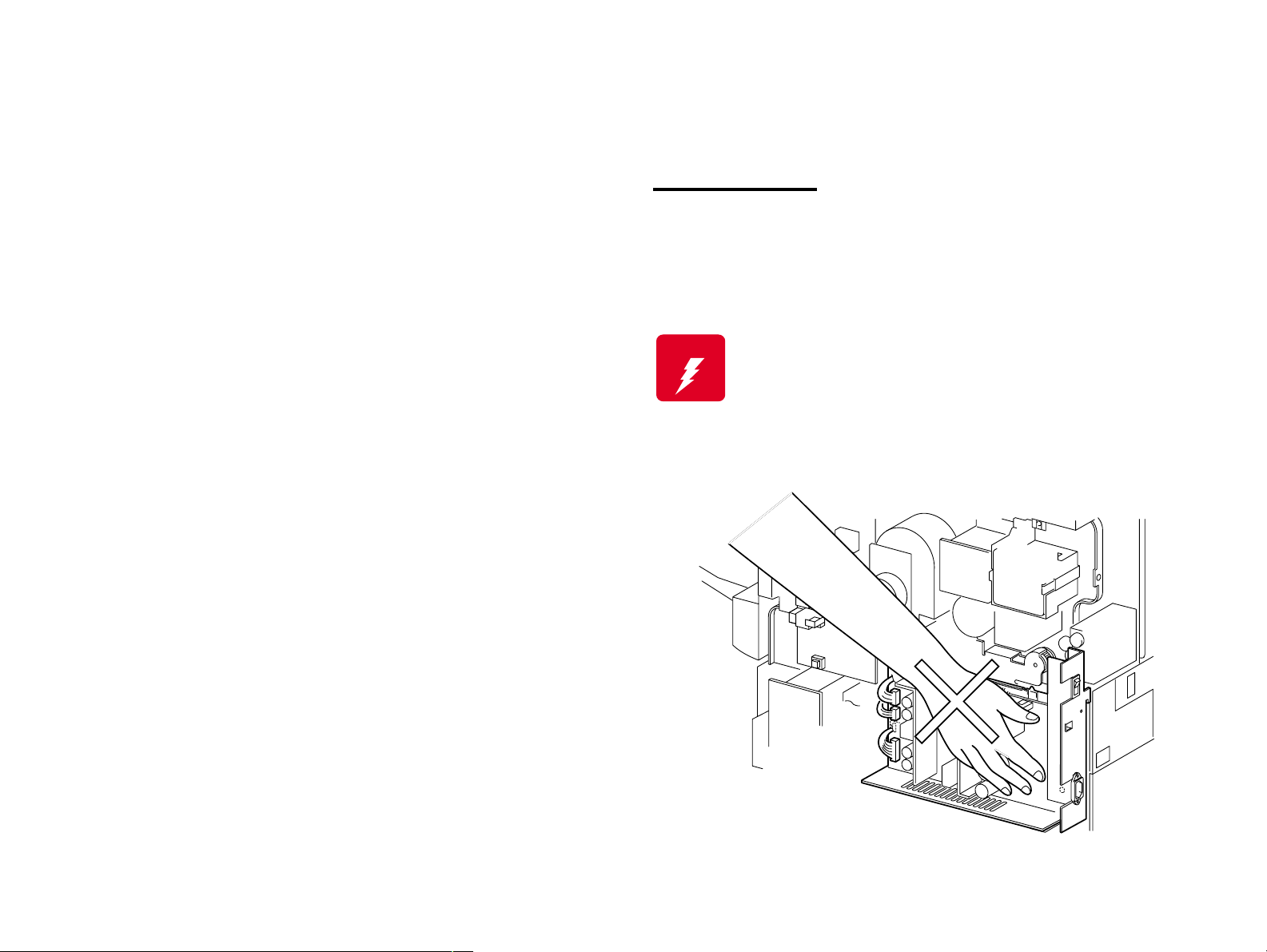
Power Supply
Before starting any service procedure, switch off the printer power and
unplug the power cord from the wall outlet. If you must service the
printer when the power is applied, be aware of the potential for electrical
shock and do all tasks by following the procedures in this manual.
W ARNING
Do not touch any live part unless you are instructed to
do so by a service procedure. The LVPS power supply
switch/inlet part is live even when the power switch has
been turned off. Do not touch any live part.
Page 7
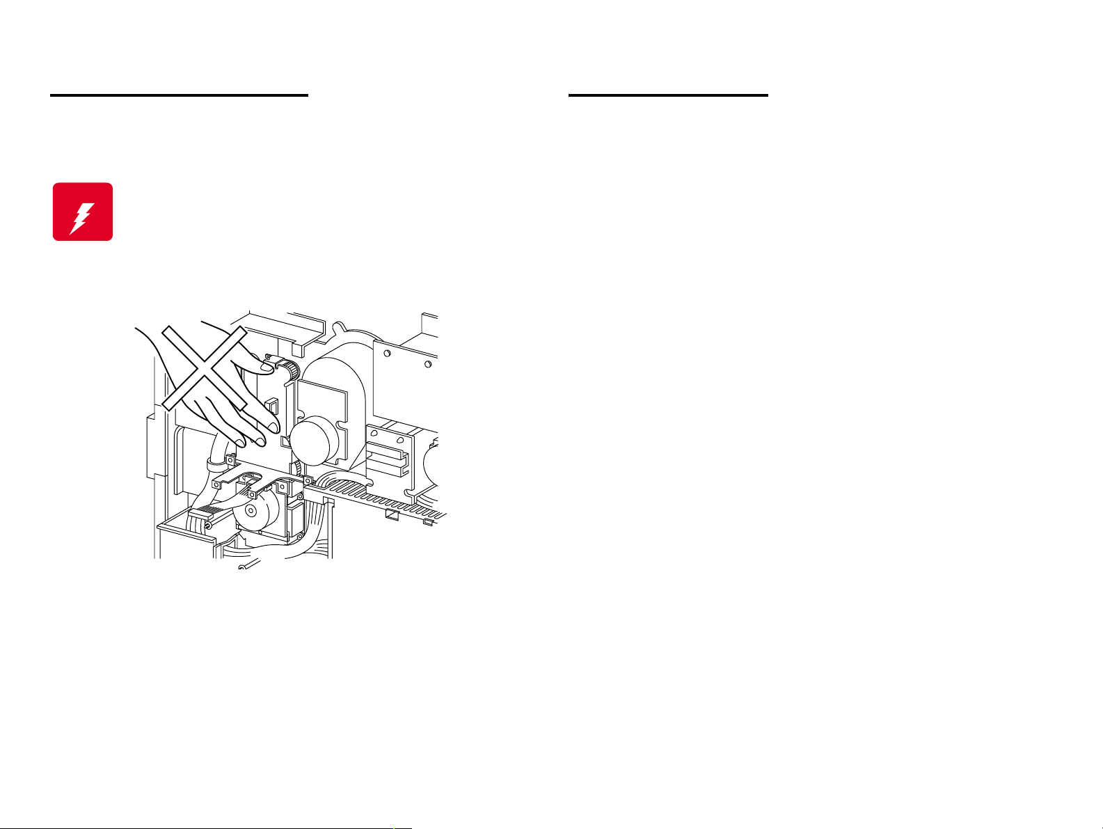
Mechanical Components
Safety Components
If you service a driving assembly (e.g., gears), first turn off the power
and unplug the power cord. Then manually rotate the assembly.
W ARNING
Do not touch the driving part (e.g., gears) while the
assembly (printer) is being driven.
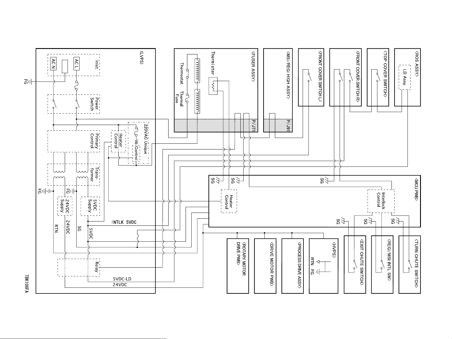
The printer is equipped with safety components (e.g., interlock
switches, fuses, thermostat) and safety switches for protecting users
and service personnel from injury and the equipment from damage.
The printer has two interlock switches, two safety switches and two
interlock connectors that serve as the main safety mechanism.
Front Cover Switch R
This switch is turned off when the Front Cover Assembly is opened.
It cuts off the power supply (24VDC, 5VDC-LD) from the power
supply unit to stop all operations and disconnects the output (5VDCLD) circuit from the power supply and stops the laser beam
emission.
This switch consists of the following two switches:
A switch that cuts off the power supply (24VDC, 5VDC-LD) to
the control circuits and related parts.
A switch that directly cuts off the power supply circuit (5VDC-LD)
to the laser beam output circuit.
Front Cover Switch L
This is a safety switch. This switch is turned off when the Front
Cover Assembly is opened, causing the printer without control units
to stop operating.
Top Cover Switch
This is an interlock switch that directly cuts off the power supply
(5VDC-LD) circuit to the laser beam output circuit. This switch is
turned off when the Top Cover Assembly is removed, cutting off the
output (5VDC-LD) circuit from the power supply unit and stopping
the laser beam emission.
Page 8
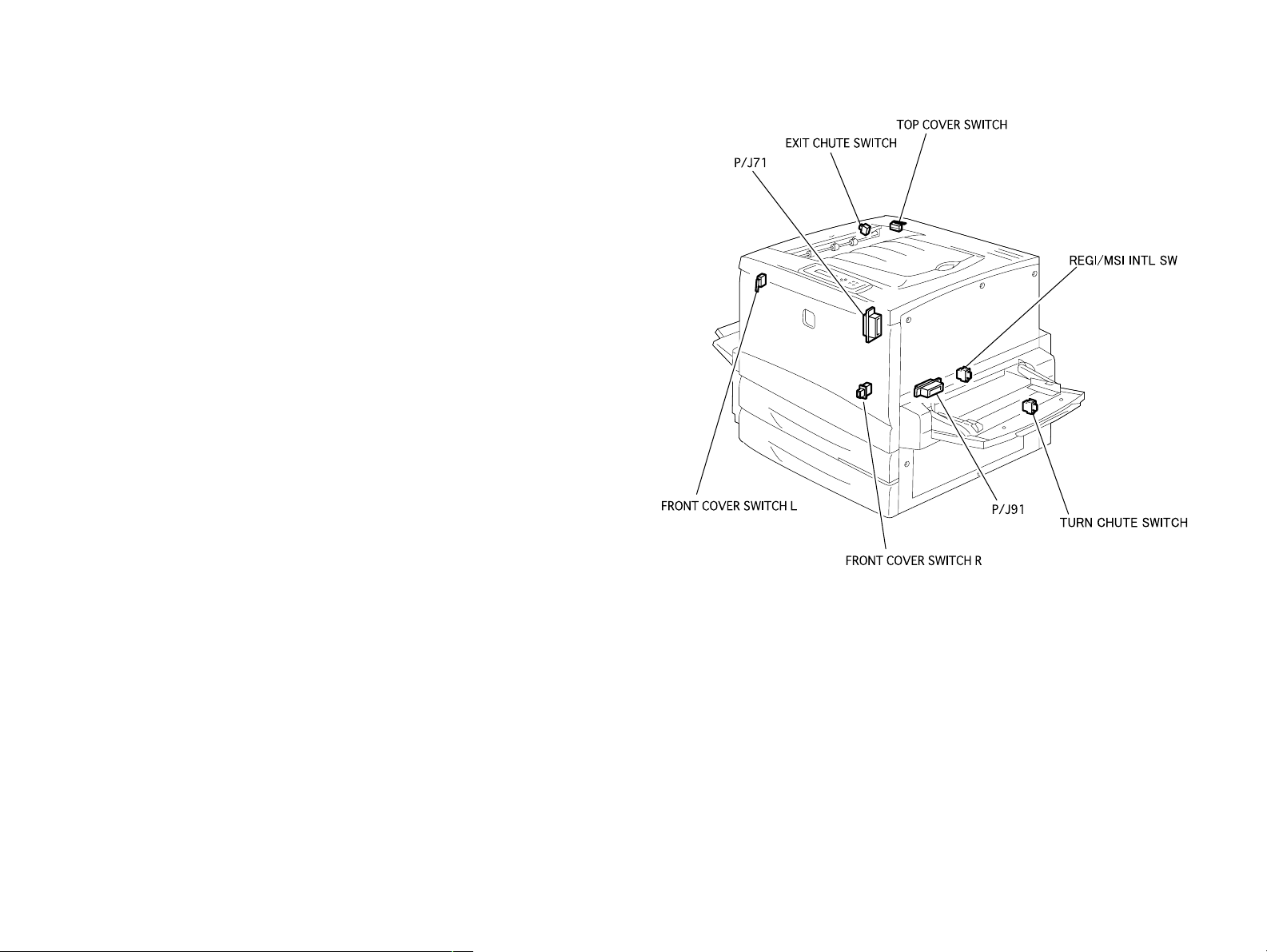
Exit Chute Switch
This switch is a safety switch. This switch is turned off when the Exit
Upper Assembly (the cover on the upper left side of the printer) is
opened.
P/J91 (Connector that connects the Main Harness Assembly and
Registration Harness Assembly)
This is an interlock connector that cuts off the power supply
(24VDC, 5VDC-LD) to the control circuit and related parts.
This connector is disconnected when the Main P/H Assembly (pullout type unit on the right side of the printer) is pulled out, cutting off
the output (24VDC, 5VDC-LD) from the power supply and stopping
the printer operation without control units.
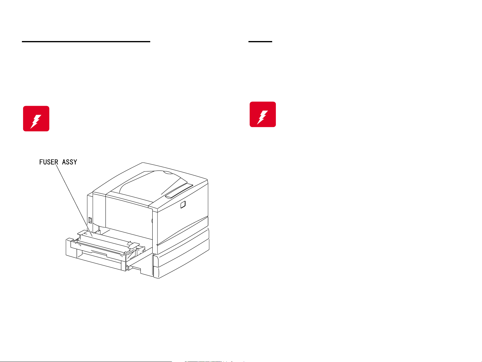
P/J71 (Connector that connects the Fuser Connector and Fuser
Harness Assembly)
This is an interlock connector that cuts off the power supply
(24VDC, 5VDC-LD) to the control circuit and related parts.
This connector is disconnected when the Fuser Assembly (pull-out
type unit on the left side of the printer) is pulled out, cutting off the
output (24VDC, 5VDC-LD) from the power supply and stopping the
printer operation without control units.
Page 9

Laser Beam
The printer has two interlock switches: the Front Cover Switch R and
the Top Cover Switch. The purpose of these switches is to turn off the
laser beam emission if any of the printer covers have been opened; this
protects the user or service personnel from exposure to the laser beam
from the ROS Assembly.
NOTE: The laser beam has a narrower frequency band and more
coherent phases than any other light (sunlight, electric light).
It has excellent monochromaticity and convergence. A thin
laser beam reaches long distances. Because of its
convergence characteristic, the laser beam converges into
one point, causing high density and high temperature. A
laser beam is harmful to the human body.
A laser beam may be emitted during a maintenance operation. Do not
turn on these interlock switches simultaneously under any
circumstances except in a normal operation.
W ARNING
Do not expose yourself to the laser beam to prevent
injury (blindness).
Do not open the cover that has the laser beam
warning label.
If you disassemble or assemble the printer, turn off
the power.
If you need to work on the printer with power applied,
strictly follow the instructions in this manual.
If you have to activate the printer while pressing the
Front Cover Switch R by hand or with a tool, remove
the Top Cover. (Do not turn on these interlock
switches simultaneously under any circumstances
except in a normal operation.)
Understand how the laser beam functions and take
maximum precautions not to injure yourself or anyone
around you.
NOTE: The laser beam in this printer is invisible.
Page 10
High Temperature Assembly
Parts
To prevent you from becoming injured or burned, do the following:
Before working with a high temperature Assembly (e.g., Fuser
Assembly), turn off the power, unplug the power cord and wait until it
cools down.
W ARNING
The high temperature Assembly is very hot
immediately after any printer operations. Wait at least
40 minutes before you start working on the printer.
To prevent you from becoming injured, keep the following in mind:
When handling heavy parts (including the printer itself), use good
posture to protect your back whenever you lift, move or place parts.
W ARNING
Be careful not to injure yourself with the sharp edges of the parts.
Do not work with wet or oily hands-you may drop a part or injure
yourself. Dry your hands first.
When pulling out a part (including a harness), do not use too much
force. Pull out the part carefully and slowly step by step.
Do not lift, move or place heavy parts in a body posture
that is likely to cause injury to yourself or cause the
part to drop.
Page 11

Consumables
Improper Printer Use
Some parts may cause a particulate explosion or fire if handled
improperly. Do not handle these parts near fire or throw into a fire.
Some materials (e.g., Developer or Fuser Oil) may cause bodily injury.
Do not swallow or inhale these materials or allow them to come in
contact with the eyes.
Help to protect those around you and follow the prohibitions against
swallowing or inhaling those materials. Be careful to protect the eyes at
all times.
Place a sheet inside or under the printer so that the floor or workbench
is protected.
If the Developer or Fuser Oil gets on your clothing, dry it with a cloth and
wash with clean water.
NOTE: The printer has the following consumable parts:
• Drum Cartridge • Waste Toner Box
• Oil Roll Assembly • Toner Cartridge Y
• Toner Cartridge M • Toner Cartridge C
• Toner Cartridge Bk
Modifying, revising, tampering with the printer, especially to the safety
mechanism, is strictly prohibited in all circumstances.
Page 12
Page 13

Manual Contents
Chapter 1 Product Descriptions
Chapter 2 Operating Principles
Chapter 3 Disassembly and Assembly / Adjustment
Chapter 4 Diagnostics
Chapter 5 Troubleshooting
Chapter 6 Maintenance
Appendix
Page 14

Revision Status
Revision Date of Issue Description
A July 10th, 2000 First issue
B July 18th, 2000 All revised parts are indicated with bold bars.
Chapter 1: Further information on 1.5.2“Support Mode” has been added.
Chapter 5: A LCD/ warning message “Worn Fuser” has been added;
In 5.1.4.4“Service-Call Error Messages”, FIPs are added to
the relating tables and some error messages are changed.
Page 15

EPSON AcuLaser C8500 Revision B
Chapter 1 PRODUCT DESCRIPTIONS
1.1 Features
1.2 Specifications
1.2.1 Basic Specifications ................................................................ 1-3
1.2.2 Paper Specifications .............................................................. 1-11
1.2.2.1 Paper Types ................................................................... 1-11
1.2.2.2 Paper Source Classification ........................................... 1-11
1.2.2.3 Printable Area ................................................................. 1-12
1.2.3 Reliability and Durability ........................................................ 1-14
1.2.4 Operating Environment ......................................................... 1-16
1.2.5 Environmental Conditions for Storage and Transportation and consumables)
1-17
1.2.6 Electrical Specifications ......................................................... 1-18
1.2.7 Process Specifications .......................................................... 1-19
1.2.8 Applicable Standards ............................................................ 1-19
1.2.9 Options and Consumable Products ....................................... 1-20
1.2.10 Regularly Replaced Parts .................................................... 1-22
1.2.11 Exterior View and Parts ....................................................... 1-23
1.2.12 Controller Specifications ...................................................... 1-26
1.2.13 Controller Configuration ...................................................... 1-27
1.3 Interface Specifications
1.3.1 Parallel Interface Specifications ............................................ 1-28
1.3.2 Ethernet Interface .................................................................. 1-30
1.3.3 Type B Interface .................................................................... 1-31
1.4 Control Panel
1.4.1 Appearance and Descriptions ............................................... 1-32
1.4.1.1 LED Description ............................................................. 1-34
1.4.2 Button Functions ................................................................... 1-34
1.5 Service Functions
1.5.1 Hex Dump Mode ................................................................... 1-36
1.5.2 Support Mode ........................................................................ 1-36
1.5.3 EEPROM Initialization ........................................................... 1-36
1.5.4 Panel Setting Value Initialization ........................................... 1-37
1.5.5 Formatting the Flash ROM Module ....................................... 1-37
1.5.6 Program ROM Update ........................................................... 1-37
1.5.7 ROM Module Copy ................................................................ 1-37
1.5.8 Maintenance Mode ................................................................ 1-37
1.5.9 Error Recovery Operation (CPU Reset) ................................ 1-37
1.6 Panel Setting
.................................................................................................... 1-2
.......................................................................................... 1-3
...................................................................... 1-28
......................................................................................... 1-32
................................................................................ 1-36
.......................................................................................... 1-38
1.6.1 Setting Methods .................................................................... 1-38
1.6.1.1 OneTouch mode ............................................................. 1-38
1.6.1.2 SelecType mode ............................................................ 1-39
1.6.2 SelecType Setting Menu List ................................................ 1-39
1.6.3 Details of Menus and Settings .............................................. 1-46
1.6.3.1 Printing Menu ................................................................. 1-46
1.6.3.2 Tray Menu ...................................................................... 1-46
1.6.3.3 Config Menu ................................................................... 1-47
1.6.3.4 Setup Menu .................................................................... 1-47
1.6.3.5 Support Menu ................................................................. 1-48
1.6.3.6 Toner Transfer Menu ...................................................... 1-48
1.6.3.7 Maintenance Menu ......................................................... 1-49
1.7 RAM Expansion
1.8 Dimensions
1.9 Engine Restrictions
..................................................................................... 1-51
............................................................................................. 1-51
.............................................................................. 1-52
Chapter 2 Operating Principles
2.1 Print Process
2.1.1 Print Process Overview ........................................................... 2-2
2.1.2 Total Print Process Schematic Diagram ................................. 2-3
2.1.3 Print Process Technical Explanation ....................................... 2-4
2.1.3.1 Electrification .................................................................... 2-4
2.1.3.2 Exposure .......................................................................... 2-5
2.1.3.3 Developing ....................................................................... 2-6
2.1.3.4 Primary Transfer (Drum --> Belt) ...................................... 2-8
2.1.3.5 Cleaning (Drum) ............................................................... 2-9
2.1.3.6 Repeat (Complete Toner Image Forming) ..................... 2-10
2.1.3.7 Secondary Transfer (Belt --> Paper) .............................. 2-11
2.1.3.8 Electrical Discharge ........................................................ 2-12
2.1.3.9 Cleaning (Belt) ................................................................ 2-13
2.1.3.10 Fixing ............................................................................ 2-13
2.2 Print Data Flow
2.2.1 Data Flow .............................................................................. 2-14
2.3 Drive Transmission Route
2.3.1 PROCESS DRIVE ASSY ...................................................... 2-15
2.3.2 FUSER MOTOR ASSY ......................................................... 2-15
2.3.3 P/H MOTOR ASSY ............................................................... 2-16
2.3.4 ROTARY MOTOR ASSY ...................................................... 2-16
............................................................................................ 2-2
....................................................................................... 2-14
.................................................................. 2-15
Page 16

EPSON AcuLaser C8500 Revision B
2.3.5 INV MOTOR ASSY (Option Duplex) ..................................... 2-17
2.3.6 Gear Layout ........................................................................... 2-18
2.3.6.1 Printer ............................................................................. 2-18
2.3.6.2 Option Duplex ................................................................. 2-19
2.4 Paper Feed
2.4.1 Paper Feed Path (When no options are installed) ................ 2-20
2.4.2 Paper Feed Path (Option Duplex) ......................................... 2-21
2.4.3 Paper Conveyance Path Layout ............................................ 2-22
2.5 Function of Main Working Parts
2.5.1 Paper Cassette ...................................................................... 2-23
2.5.2 Paper Feeder ........................................................................ 2-24
2.5.3 MSI/Paper Transportation I ................................................... 2-26
2.5.4 MSI/Paper Transportation II .................................................. 2-27
2.5.5 Xerographics I ....................................................................... 2-29
2.5.6 Xerographics II ...................................................................... 2-30
2.5.7 Development ......................................................................... 2-32
2.5.8 IBT I ....................................................................................... 2-34
2.5.9 IBT II ...................................................................................... 2-35
2.5.10 Fusing I ................................................................................ 2-37
2.5.11 Fusing II ............................................................................... 2-38
2.5.12 Paper Exit ............................................................................ 2-39
2.5.13 Drive .................................................................................... 2-40
2.5.14 Electrical .............................................................................. 2-42
2.5.15 Option Duplex ...................................................................... 2-44
2.6 Operation Mode
2.7 Control
2.7.1 Paper Size Control ................................................................ 2-49
2.7.2 Cassette 2/Cassette 3 paper size control .............................. 2-50
2.7.3 Paper Supply Unit Selection Control ..................................... 2-51
2.7.4 OHP Front/Back Detection Control ....................................... 2-51
2.7.5 ROS Control .......................................................................... 2-52
2.7.5.1 Scanner Motor Operation ............................................... 2-52
2.7.5.2 ROS Warm-Up ............................................................... 2-52
2.7.5.3 Quantity of Light Control ................................................. 2-52
2.7.6 Process Control ..................................................................... 2-53
2.7.6.1 Potential Control ............................................................. 2-53
2.7.6.2 Toner Concentration Control (PCDC) ............................. 2-54
2.7.6.3 Toner Concentration Control (ADC) ............................... 2-54
2.7.6.4 ADC Solenoid Operation ................................................ 2-55
............................................................................................. 2-20
....................................................... 2-23
.................................................................................... 2-48
..................................................................................................... 2-49
2.7.7 XERO. Control ...................................................................... 2-56
2.7.7.1 Operation when DRUM CARTRIDGE is Replaced ........ 2-56
2.7.7.2 DRUM CARTRIDGE Life Detection Control ................... 2-56
2.7.7.3 WASTE TONER BOX Full Detection Control ................. 2-57
2.7.8 DEVE. Control ....................................................................... 2-59
2.7.8.1 Home Position Detection Operation ............................... 2-59
2.7.8.2 Toner Cartridge Presence Detection Position ................ 2-60
2.7.8.3 Toner Cartridge New/Old Detection Position ................. 2-60
2.7.8.4 Developing Position ........................................................ 2-60
2.7.8.5 Detection Method Accompanying DEVE. Control .......... 2-61
2.7.9 IBT Control ............................................................................ 2-63
2.7.9.1 Primary Transfer (Drum --> Belt) .................................... 2-63
2.7.9.2 Secondary Transfer (Belt-->Paper) ................................ 2-64
2.7.9.3 Belt Cleaning .................................................................. 2-66
2.7.9.4 IBT-related life detection control ..................................... 2-67
2.7.10 Transfer Layout Control ...................................................... 2-68
2.7.11 FUSER Control ................................................................... 2-70
2.7.11.1 Fuser Control Method ................................................... 2-70
2.7.11.2 Control for WARM UP Mode ........................................ 2-70
2.7.11.3 READY / LIGHT SLEEP / DEEP SLEEP Modes Control 2-70
2.7.11.4 Control in PRINTING Mode .......................................... 2-70
2.7.11.5 FUSER skidding ........................................................... 2-71
2.7.11.6 Prevention of a FUSER NIP scar ................................. 2-71
2.7.11.7 MAIN FUSER ASSY Life Detection Control ................. 2-71
2.8 Controller Operating Principles
........................................................ 2-72
Chapter 3 Disassembly/Assembly/Adjustment
3.1 Overview
3.1.1 Precautions for Disassembly, Assembly and Adjustment ....... 3-2
3.1.1.1 Precaution for Handling the Lithium Battery ..................... 3-2
3.1.2 Tools ....................................................................................... 3-3
3.1.3 Items to Check after Assembly ............................................... 3-3
3.2 Disassembly/Assembly Procedures
3.2.1 Exterior View and Part Names ................................................ 3-5
3.2.2 Removing/Replacing the Consumables .................................. 3-6
3.2.3 Updating the Main Controller Program ROM .......................... 3-6
3.2.3.1 Updating the ROM using a standard parallel interface ..... 3-6
3.2.3.2 Updating by copying from the FLASH ROM module ........ 3-7
3.2.3.3 Formatting the FLASH ROM Module ............................... 3-8
.................................................................................................... 3-2
.................................................. 3-3
Page 17

EPSON AcuLaser C8500 Revision B
3.2.4 Updating the MCU PWB (Mechanical Controller) Firmware ... 3-9
3.2.5 Cover ..................................................................................... 3-10
3.2.5.1 FRONT COVER ASSY (PL1.1.1) Removal .................... 3-10
3.2.5.2 FRONT MID COVER (PL1.1.6) Removal ....................... 3-10
3.2.5.3 FRONT LOWER COVER (PL1.1.5) Removal ................ 3-11
3.2.5.4 TOP COVER ASSY (PL1.1.20) Removal ....................... 3-12
3.2.5.5 L/H INNER COVER ASSY (PL1.1.10) Removal ............ 3-13
3.2.5.6 IBT INNER COVER ASSY (PL1.1.14) Removal ............ 3-14
3.2.5.7 R/H INNER COVER ASSY (PL1.1.15) Removal ............ 3-15
3.2.5.8 REAR COVER ASSY (PL1.1.30) Removal .................... 3-16
3.2.5.9 FILTER ASSY (PL1.1.32) Removal ............................... 3-17
3.2.5.10 LEFT LOWER COVER (PL1.1.40) Removal ................ 3-17
3.2.5.11 RIGHT COVER ASSY (PL1.1.51) Removal ................. 3-18
3.2.5.12 OPERATION PANEL (PL1.1.60) Removal ................... 3-18
3.2.5.13 RIGHT LOWER COVER (PL1.1.50) Removal ............. 3-19
3.2.6 Paper Tray ............................................................................. 3-20
3.2.6.1 UNIVERSAL CASSETTE (PL2.1.1) Removal ................ 3-20
3.2.6.2 FRONT SNUBBER (PL2.1.9) Removal .......................... 3-21
3.2.6.3 END GUIDE (PL2.1.16), SECTOR GEAR (PL2.1.18) Removal
3-22
3.2.7 Paper Feeder ........................................................................ 3-24
3.2.7.1 TURN IN CHUTE (PL3.1.21) Removal ........................... 3-24
3.2.7.2 TURN ROLL ASSY (PL3.1.23) Removal ........................ 3-26
3.2.7.3 FEED ROLL (PL3.1.31) Removal .................................. 3-27
3.2.7.4 FEED SOLENOID (PL3.1.35) Removal ......................... 3-28
3.2.7.5 FEED ROLL ASSY (PL3.1.29) Removal ........................ 3-29
3.2.7.6 SIZE SWITCH ASSY (PL3.1.5) Removal ....................... 3-30
3.2.7.7 CASSETTE N/P SENSOR ASSY (PL3.1.30) Removal .. 3-31
3.2.7.8 LOW PAPER SENSOR (PL3.1.18) Removal ................. 3-32
3.2.7.9 TRAY NO PAPER SENSOR (PL3.1.9) Removal ........... 3-32
3.2.8 MSI/Paper Transportation ..................................................... 3-33
3.2.8.1 MSI/REGI HIGH ASSY (PL4.1.5) Removal .................... 3-33
3.2.8.2 MSI GUIDE SWITCH (PL4.1.18) Removal ..................... 3-33
3.2.8.3 MSI ASSY (PL4.1.6) Removal ....................................... 3-34
3.2.8.4 MSI BASE ASSY (PL4.1.20) Removal ........................... 3-35
3.2.8.5 MSI FEED ASSY (PL4.1.30) Removal ........................... 3-35
3.2.8.6 MAIN P/H FRAME ASSY (PL4.1.40) Removal .............. 3-36
3.2.8.7 BOTTOM PLATE SENSOR (PL4.2.10) Removal ........... 3-36
3.2.8.8 LIFT UP FRAME ASSY (PL4.2.20) Removal ................. 3-37
3.2.8.9 EMPTY SENSOR (PL4.3.5) Removal ............................ 3-37
3.2.8.10 PITCH SENSOR (PL4.3.6) Removal ........................... 3-38
3.2.8.11 MSI FEED FRAME ASSY (PL4.3.20) Removal ........... 3-38
3.2.8.12 LEVEL SENSOR (PL4.3.23) Removal ......................... 3-39
3.2.8.13 P/REGI ROLL ASSY (PL4.4.3) Removal ..................... 3-40
3.2.8.14 PRE REGI CLUTCH ASSY (PL4.4.49) Removal ......... 3-40
3.2.8.15 REGI CLUTCH ASSY (PL4.4.5) Removal ................... 3-41
3.2.8.16 REGI RUBBER ROLL ASSY (PL4.4.7) Removal ......... 3-42
3.2.8.17 REGI METAL ROLL (PL4.4.8) Removal ...................... 3-43
3.2.8.18 IBT REGI CHUTE (PL4.4.14) Removal ........................ 3-44
3.2.8.19 REGI SENSOR (PL4.4.24) Removal ........................... 3-45
3.2.8.20 OHP SENSOR (PL4.4.25) Removal ............................ 3-46
3.2.9 Xerographics ......................................................................... 3-47
3.2.9.1 DRUM CARTRIDGE (PL6.1.10) Removal ..................... 3-47
3.2.9.2 WASTE TONER BOX (PL6.1.12) Removal ................... 3-48
3.2.9.3 ROS ASSY (PL6.1.1) Removal ...................................... 3-49
3.2.9.4 ADC SENSOR ASSY (PL6.1.20) Removal .................... 3-50
3.2.9.5 XL RAIL ASSY (PL6.1.40) Removal .............................. 3-51
3.2.9.6 WASTE TONER SENSOR (PL6.1.42) Removal ............ 3-52
3.2.9.7 TONER BOX SENSOR (PL6.1.43) Removal ................. 3-52
3.2.9.8 ERASE LAMP ASSY (PL6.1.30) Removal ..................... 3-53
3.2.10 Development ....................................................................... 3-54
3.2.10.1 Toner Cartridge (PL7.1.1, PL7.1.2, PL7.1.3, PL7.1.4) Removal
3-54
3.2.10.2 DEVELOPER ASSY (PL7.1.10, PL7.1.20, PL7.1.30, PL7.1.40) Removal
3-55
3.2.10.3 ROTARY SENSOR (PL7.2.22) Removal ..................... 3-57
3.2.10.4 ROTARY FRAME ASSY (PL7.2.2) Removal ............... 3-58
3.2.10.5 CARTRIDGE SENSOR (PL7.2.26) Removal ............... 3-60
3.2.11 IBT ....................................................................................... 3-61
3.2.11.1 TENSION LEVER (PL8.1.21) Removal ........................ 3-61
3.2.11.2 TRANSFER HIGH ASSY (PL8.1.20) Removal ............ 3-62
3.2.11.3 BELT CLEANER ASSY (PL8.1.23) Removal ............... 3-63
3.2.11.4 2ND BTR ASSY (PL8.1.22) Removal .......................... 3-64
3.2.11.5 2ND BTR CAM ASSY (PL8.1.1) Removal ................... 3-65
3.2.11.6 AUGER HIGH ASSY (PL8.1.6) Removal ..................... 3-66
3.2.11.7 IBT BELT ASSY (PL8.2.2) Removal ............................ 3-67
3.2.11.8 TR0 SENSOR (PL8.2.33) Removal ............................. 3-69
3.2.11.9 BTR CAM CLUTCH (PL8.3.4) Removal ....................... 3-69
3.2.12 Fusing ................................................................................. 3-70
3.2.12.1 FUSER ASSY (PL9.1.1) Removal ................................ 3-70
Page 18

EPSON AcuLaser C8500 Revision B
3.2.12.2 MAIN FUSER ASSY (PL9.1.2) Removal ...................... 3-71
3.2.12.3 UPPER GUIDE ASSY (PL9.2.20) Removal ................. 3-72
3.2.12.4 FUSER UPPER ASSY (PL9.2.30) Removal ................ 3-73
3.2.12.5 H/R HEATER (PL9.2.37) Removal ............................... 3-74
3.2.12.6 P/R HEATER (PL9.2.38) Removal ............................... 3-75
3.2.12.7 LOWER GUIDE ASSY (PL9.2.13) Removal ................ 3-76
3.2.12.8 FUSER EXIT SENSOR-1 (PL9.2.3) Removal .............. 3-76
3.2.12.9 FUSER EXIT SENSOR-2 (PL9.2.4) Removal .............. 3-77
3.2.12.10 HEAT ROLL (PL9.2.25) Removal .............................. 3-78
3.2.12.11 PRESSURE ROLL (PL9.2.10) Removal .................... 3-79
3.2.12.12 TEMP. SENSOR ASSY (PL9.2.6) Removal ............... 3-80
3.2.12.13 EXCHANGE CHUTE (PL9.3.17) Removal ................. 3-81
3.2.12.14 EXCHANGE SOLENOID (PL9.3.22) Removal ........... 3-82
3.2.12.15 CLEANER CAM SOLENOID (PL9.4.24) Removal ..... 3-83
3.2.12.16 CLEANER CAM ASSY (PL9.4.25) Removal .............. 3-84
3.2.12.17 EXIT-1 ROLL ASSY (PL9.3.14) Removal .................. 3-85
3.2.12.18 FUSER IN SENSOR (PL9.4.4) Removal .................... 3-86
3.2.12.19 FUSER CHUTE FAN (PL9.4.10) Removal ................. 3-87
3.2.12.20 FUSER BAFFLE ASSY (PL9.2.41) Removal ............. 3-88
3.2.13 Paper Exit ............................................................................ 3-88
3.2.13.1 EXIT TRAY ASSY (PL10.1.10) Removal ..................... 3-89
3.2.13.2 EXIT UPPER ASSY (PL10.1.2) Removal ..................... 3-89
3.2.13.3 EXIT LOWER ASSY (PL10.1.1) Removal .................... 3-90
3.2.13.4 EXIT-2 ROLL ASSY (PL10.2.5) Removal .................... 3-90
3.2.13.5 EXIT-3 ROLL ASSY (PL10.2.6) Removal .................... 3-91
3.2.13.6 FUSER FAN-1 (PL10.2.15) Removal ........................... 3-91
3.2.13.7 TOP EXIT SENSOR (PL10.2.12) Removal .................. 3-92
3.2.13.8 EXIT CHUTE SWITCH (PL10.2.13) Removal .............. 3-92
3.2.14 Drive .................................................................................... 3-92
3.2.14.1 P/H DRIVE ASSY (PL11.1.1) Removal ........................ 3-93
3.2.14.2 FUSER DRIVE ASSY (PL11.1.2) Removal .................. 3-94
3.2.14.3 FUSER MOTOR ASSY (PL11.1.4) Removal ............... 3-95
3.2.14.4 P/H MOTOR ASSY (Pl11.1.5) Removal ....................... 3-95
3.2.14.5 DRIVE MOTOR PWB (PL11.1.6) Removal .................. 3-96
3.2.14.6 PROCESS DRIVE ASSY (PL11.1.10) Removal .......... 3-96
3.2.14.7 ROTARY MOTOR ASSY (PL11.1.20) Removal ........... 3-97
3.2.14.8 ROTARY MOTOR DRIVE PWB (PL11.1.21) Removal 3-97
3.2.14.9 DISPENSE CLUTCH ASSY (PL11.1.22) Removal ...... 3-98
3.2.14.10 DEVE. CLUTCH ASSY (PL11.1.23) Removal ............ 3-98
3.2.15 Frame .................................................................................. 3-99
3.2.15.1 DEVE. TIE PLATE (PL12.1.3) Removal ....................... 3-99
3.2.16 Electrical ............................................................................ 3-100
3.2.16.1 LVPS (PL13.1.1) Removal ......................................... 3-100
3.2.16.2 HVPS (PL13.1.2) Removal ......................................... 3-101
3.2.16.3 TOP COVER SWITCH (PL13.1.3) Removal .............. 3-102
3.2.16.4 DEVE. FAN (PL13.1.5) Removal ............................... 3-102
3.2.16.5 MCU PWB (PL13.2.1) Removal ................................. 3-103
3.2.16.6 FRONT COVER SWITCH R (PL13.2.3) Removal ..... 3-104
3.2.16.7 FRONT COVER SWITCH L (PL13.2.4) Removal ...... 3-105
3.2.16.8 ENVIRONMENT SENSOR (PL13.2.5) Removal ........ 3-106
3.2.17 Controller ........................................................................... 3-107
3.2.17.1 CONTROLLER PWB (PL14.1.10) Removal ............... 3-107
3.2.17.2 CONTROLLER FAN (PL14.1.2) Removal .................. 3-109
3.2.17.3 CONT. CHASSIS ASSY (PL14.1.1) Removal ............ 3-110
3.2.17.4 Lithium Battery Removal ............................................ 3-111
3.3 Adjustment
3.3.1 NIP Pressure of the MAIN FUSER ASSY ........................... 3-112
3.3.2 Development ....................................................................... 3-113
............................................................................................ 3-112
Chapter 4 Diagnostics
4.1 Diagnostics by the Diagnostic Commander
4.1.1 Overview ................................................................................. 4-2
4.1.2 Method of Printing Test Prints ................................................. 4-2
4.1.3 Test Print Patterns .................................................................. 4-4
4.2 Diagnostics Commander
4.2.1 Overview ................................................................................ 4-5
4.2.1.1 Configuration .................................................................... 4-5
4.2.1.2 Overview of the Diagnostic Commander .......................... 4-6
4.2.1.3 Overview of the DIAG. PWB ............................................ 4-6
4.2.2 Preparation .............................................................................. 4-7
4.2.2.1 Personal Computer .......................................................... 4-7
4.2.2.2 Installation of the Diagnostics Commander ...................... 4-7
4.2.2.3 Uninstalling the Diagnostics Commander ........................ 4-8
4.2.2.4 Connection of the diagnostics tools (MCU PWB) ............. 4-8
4.2.2.5 Connection of the diagnostics tools (Option Connector) .. 4-9
4.2.3 Commands / Statuses ............................................................. 4-9
4.2.3.1 Overview of Commands and Statuses ............................. 4-9
4.2.3.2 Data Format ................................................................... 4-10
4.2.3.3 Categories of Commands / Statuses .............................. 4-10
....................................................................... 4-5
.................................... 4-2
Page 19

EPSON AcuLaser C8500 Revision B
4.2.4 Operating the Diagnostics Commander ................................ 4-11
4.2.4.1 Starting Up the Diagnostics Commander ....................... 4-11
4.2.4.2 Communications Connection ......................................... 4-11
4.2.4.3 Log Display ..................................................................... 4-12
4.2.4.4 [Manual] Tab Operation .................................................. 4-13
4.2.4.5 [Auto] Tab Procedures ................................................... 4-15
4.2.5 Diagnostics Execution ........................................................... 4-22
4.2.5.1 Diagnostics Execution Procedures ................................. 4-22
4.2.5.2 Diagnostics Types .......................................................... 4-22
4.2.5.3 Test Print ........................................................................ 4-23
4.2.5.4 Digital Input Test ............................................................ 4-24
4.2.5.5 Digital Input Test Device Code ....................................... 4-24
4.2.5.6 Digital Output Test .......................................................... 4-30
4.2.5.7 Digital Output Test Device Code .................................... 4-31
4.2.5.8 Analog Input Test .......................................................... 4-40
4.2.5.9 Analog Input Test Device Code ...................................... 4-41
4.2.5.10 Analog Output Test ...................................................... 4-43
4.2.5.11 Analog Output Test Device Code ................................. 4-44
4.2.5.12 EEPROM Read ............................................................ 4-46
4.2.5.13 EEPROM Write ............................................................ 4-49
4.2.5.14 EEPROM Initialize ........................................................ 4-52
4.2.5.15 NVM List ....................................................................... 4-53
4.2.6 Count Accumulation Value Read/Write ................................. 4-67
4.2.6.1 Read ............................................................................... 4-68
4.2.6.2 Write .............................................................................. 4-69
4.2.7 Command/Status List ............................................................ 4-70
4.2.7.1 Paper, Media & Output Control ...................................... 4-70
4.2.7.2 Printing/Status Control ................................................... 4-74
4.2.7.3 Parameter Control .......................................................... 4-80
4.2.7.4 Diagnostics Control ....................................................... 4-83
4.2.8 Error / Status Code ................................................................ 4-84
Chapter 5 Troubleshooting
5.1 Overview
5.1.1 Troubleshooting Procedure ..................................................... 5-2
5.1.2 Preliminary Checks ................................................................. 5-2
5.1.3 1.3 Precautions When Performing Work ................................. 5-3
5.1.4 Self-Diagnostic Function by LCD Message ............................. 5-4
5.1.4.1 Status Message ................................................................ 5-7
5.1.4.2 Error Message .................................................................. 5-9
................................................................................................... 5-2
5.1.4.3 Warning Message .......................................................... 5-15
5.1.4.4 Service-Call Error Messages .......................................... 5-19
5.2 Level 1 FIP (Fault Isolation Procedure)
5.2.1 Precautions When Using FIP (Fault Isolation Procedure) ..... 5-21
5.2.2 FIP Entry Chart ..................................................................... 5-22
5.3 Level 2 FIP (Fault Isolation Procedure
5.4 Picture Image Trouble
5.4.1 Picture Image Troubleshooting Entry Chart ........................ 5-120
5.5 Picture Quality FIP
........................................................................ 5-120
.............................................................................. 5-120
........................................... 5-21
............................................ 5-80
Chapter 6 Maintenance
6.1 About On-Site Servicing
6.1.1 On-site Service Flow ............................................................... 6-3
6.1.2 Description of the On-site Service ........................................... 6-4
6.2 Maintenance Menu
6.2.1 Entry to the Maintenance Menu .............................................. 6-8
6.2.2 Engine Status Sheet ............................................................... 6-9
6.3 Consumable Replacement
6.3.1 TONER CARTRIDGE Replacement ..................................... 6-14
6.3.2 PHOTOCONDUCTOR UNIT Replacement ........................... 6-17
6.3.3 WASTE TONER BOX Replacement ..................................... 6-19
6.4 Regularly Replaced Parts Replacement
6.5 Main After-Sales Parts Replacement
6.6 Installation
............................................................................................... 6-21
........................................................................ 6-2
.................................................................................. 6-7
.................................................................. 6-13
......................................... 6-21
............................................... 6-21
Chapter 7 APPENDIX
7.1 Overview
7.2 Parts List and Exploded Diagrams
7.2.1 How to Use the Parts List and Exploded Diagrams ................ 7-2
7.2.2 Parts List Tables ..................................................................... 7-3
7.2.3 Exploded Diagrams ................................................................. 7-7
7.3 Wiring Diagrams
7.3.1 P/J Locations ......................................................................... 7-19
7.3.2 Plug and Jack (P/J) Location Tables ..................................... 7-23
7.4 Wiring Diagrams and Signal Information
7.4.1 Overall Wiring Connection Diagram ...................................... 7-28
.................................................................................................... 7-2
..................................................... 7-2
.................................................................................... 7-19
........................................ 7-28
Page 20

EPSON AcuLaser C8500 Revision B
7.4.2 Wiring and Signal Descriptions between Components ......... 7-30
7.4.2.1 Configuration .................................................................. 7-30
7.4.3 Notation on the Diagrams for the Wiring and Signal Descriptions be-
tween Components ............................................................................ 7-32
7.5 Component Layout
7.6 Circuit Diagrams
.............................................................................. 7-59
................................................................................... 7-61
Page 21

PRODUCT DESCRIPTIONS
CHAPTER
1
Page 22

EPSON AcuLaser C8500 Revision B
1.1 Features
The EPSON AcuLaser C8500 is a non-impact color page printer with a
resolution of 600 dpi. It has mainly improved on the print speed; 6 ppm for color
print (A4) and 26 ppm for monochrome print (A4). The main features of the
printer are as follows:
ENGINE FEATURES
1. High speed print engine at a print speed of 6 ppm for color, and 26 ppm for
B/W (when printing A4). Paper sizes of A5 to A3W are supported.
2. Duplex printing supported. The engine is capable of printing true 600 dpi
high resolution in full color.
3. Higher quality printing is possible with high quality plain paper.
4. Capable of printing thick paper, coated paper and transparencies
(exclusive transparencies).
5. Features easy maintenance as a color laser printer.
6. Standard paper feed includes 2 bins; MP tray (up to 150 sheets, A3W
supported) and standard universal cassette (up to 250 sheets, A3
supported).
Paper feeding of maximum 1400 sheets from 4 bins is possible with a
optional lower cassette (Large Capacity Paper Unit, A3 supported)
installed.
Paper feeding of maximum 900 sheets from 3 bins is possible with the
optional a optional lower paper cassette (500-Sheet Paper Cassette Unit,
A3 supported) installed.
7. Standard paper output can output 250 sheets Face-down and 150 sheets
Face-up.
2. Color technologies
3. EPSON RIP Station 5300 (On-board option for EPSON Color Copy
4. Equipped with 2 standard interfaces.
5. By expanding memory with RAM DIMMs, the following functions can be
6. Equipped with RTC (Real Time Clock). (For job management)
7. HDD (optional) can be installed.
SOFTWARE FEATURES
Standard RAM is 64 MB.
By installing additional RAM (3 slots), the maximum memory size can
be expanded to 768 MB. (Note: keep the standard RAM 64MB
installed and use other two RAM slots if the memory needs to be
expanded.)
Equipped with Enhanced ASIC (VIP1a).
Data compression has been incorporated into the hardware to achieve
high speed processing.
Equipped with AcuLaser Color Halftoning, CRIT (Color RIT).
Station) supported.
IEEE 1284 compliant and ECP compatible parallel Interface
Ethernet interface (10Base-T/100Base-TX)
enhanced and speeded up.
Drawing area in AcuLaser Color Halftoning
Print Speed
Resolution
CONTROLLER FEATURES
1. Installed emulations
Standard : ESC/Page-Color mode
1. Newly designed High Speed Controller
A new 64-bit RISC CPU — R5000 - 266 MHz
64-bit high speed memory — SDRAM DIMM (The same RAM as in the
EPSON EPL-C8200 can be used.)
B/W printing supported by ESC/Page Color (Automatic discrimination
between color and B/W is speeded up)
Standard : LJ4, GL2, ESCP2, FX, I239X, ESC/Page (B/W) mode (fullcompatibility with Cardinal+)
Option : Adobe Postscript Level3 (Peacock-B /PostScript module)
PRODUCT DESCRIPTIONS Features 1-2
Page 23
EPSON AcuLaser C8500 Revision B
Option : Color Copy Unit (EPSON RIP Station 5300)
2. Through EJL, PJL and Printer MIB, the printer status and printer
environment are monitored.
3. Remote panel function through a Web browser using EPSON Net Web
Assist.
4. When flash DIMM is installed, ROM update function is available. (RCC
supported)
1.2 Specifications
This section describes specifications for EPSON AcuLaser C8500.
1.2.1 Basic Specifications
Method
5. Engine controller ROM(Flash) update function available
6. HP LaserJet4000 installed, the compatible font with 80 Scalable font
installed, NLSP font ROM installed, Euro Symbol supported.
7. Engine adjustment function enabled by DIAG mode.
8. When a HDD (option) is installed, Electronic sorting, I/F reception buffer
expansion (only for Ethernet I/F) and font registration when PostScript3
mode can be equipped.
9. Job management functions (available only for the job received from
Network I/F)
10. Transfer voltage adjustment function
11. The default value for Gamma is changed to 1.8.
Semi-conductive laser beam scanning and dry electrophotographic process
RESOLUTION
600 dpi
Print mode
B/W mode: Standard monochrome print mode that supports
the fastest speed.
Color mode: Color mode which uses the color toner of Y, M, C,
and BK.
SPEED MODE
Standard mode: Transports paper at the highest speed supported
by the printer.
Half speed mode: In this mode, image on thick paper (over 105g/
Low speed mode: In this mode, paper is transported slowly to cause
2
m
), envelopes, and monochrome image on OHP
sheet are well fixed.
color image on OHP sheet to be fixed well.
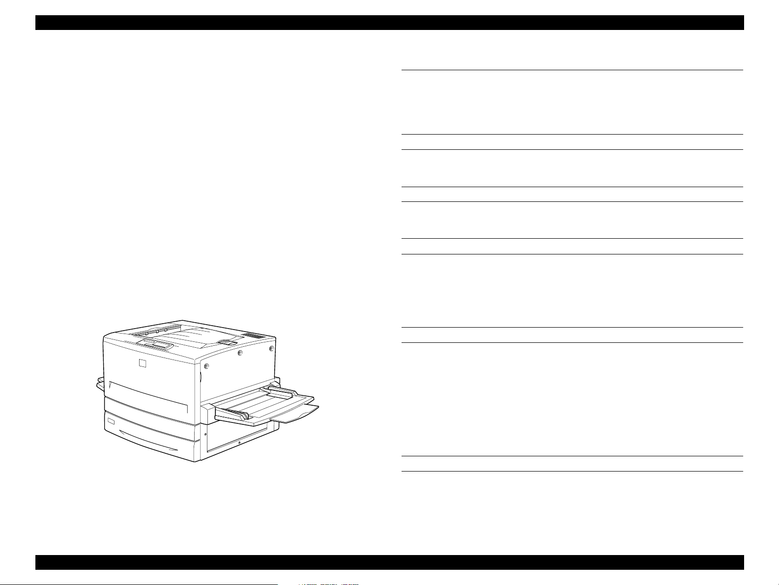
PRINT SPEED
Figure 1-1. Exterior View of the EPSON AcuLaser C8500
See Table 1-1.
PRODUCT DESCRIPTIONS Specifications 1-3
Page 24
EPSON AcuLaser C8500 Revision B
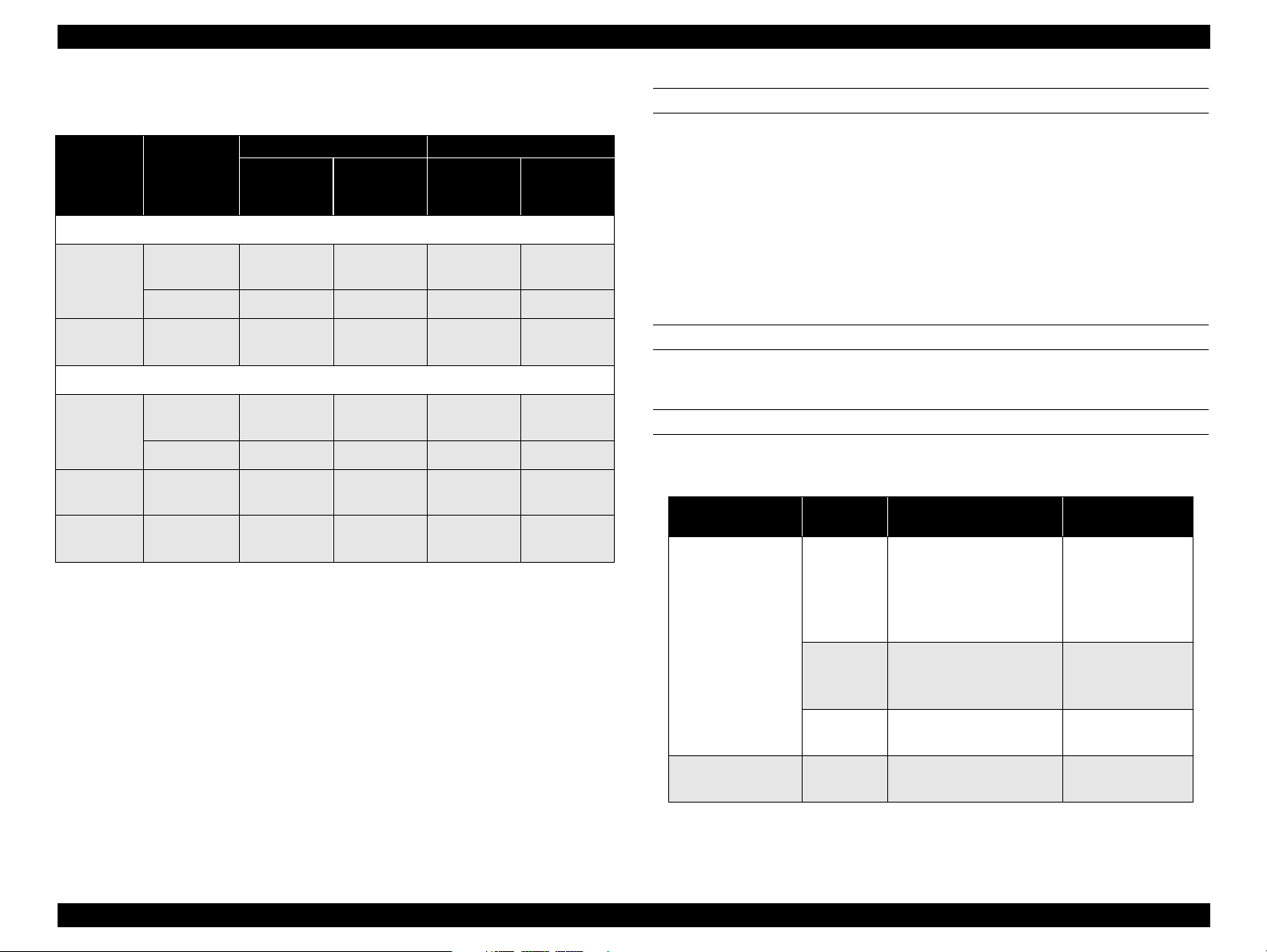
First print
Table 1-1. Speed Mode
Face-up: B/W 10.9 seconds or less (LT/A4 LEF)
Color 25.9 seconds or less (LT/A4 LEF)
Face-down: B/W 13.9 seconds or less (LT/A4 LEF)
Color 28.9 seconds or less (LT/A4 LEF)
NOTE:
First print is defined as the duration taken after receiving the start
command until outputting the first print. It is applicable when a
feeder is selected in the standard mode. (Not applied during the
process control operation.)
Print mode
Monochrom print mode
Standard
mode
Speed
mode
Single sided
print
Duplex print 20.2 PPM 19.8 PPM 11.0 PPM 10.8 PPM
LT/A4 LEF*1 (2UP*2)
Standard
tray/
cassette
26.1 PPM 24.8 PPM 13.8 PPM 13.5 PPM
Optional
paper
cassettes
*4
B (LD)/A3 SEF
Standard
tray/
cassette
*3
Optional
paper
cassettes
Half speed
mode
Color print mode
Standard
mode
Half speed
mode
Low speed
mode
*1: LEF, or Long Edge Feed, means the longer edge of the paper is the top toward
the paper feed direction.
*2: In this mode, the printer creates two print images on the IBT belt and the images
are transferred in sequence onto two sheets of paper. It is available for LT/A4
(LEF) or smaller.
*3: SEF, or Short Edge Feed, means the shorter edge of the paper is the top toward
the paper feed direction.
*4: 500-Sheet Paper Cassette Unit, Large Capacity Paper Unit
Single sided
print
Single sided
print
Duplex print 6.0 PPM 6.0 PPM 3.0 PPM 3.0 PPM
Single sided
print
Single sided
print
4.0 PPM - 2.0 PPM -
6.0 PPM 6.0 PPM 3.0 PPM 3.0 PPM
2.7 PPM - 1.3 PPM -
2.2 PPM - 1.2 PPM -
WARM-UP TIME
Within 300 seconds (at 22 °C, 55% Rh, rated voltage)
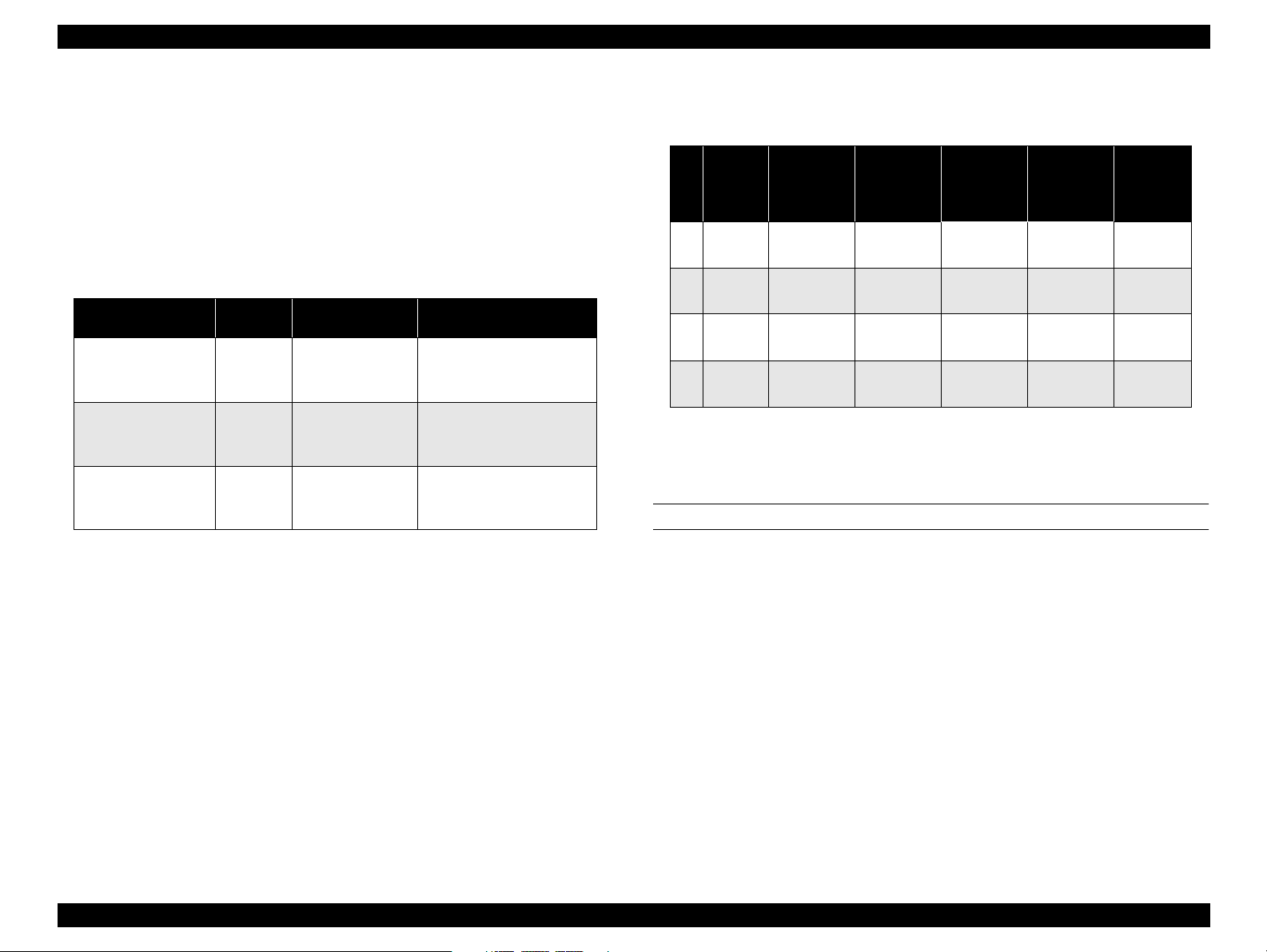
PAPER HANDLING
Standard MSI, Standard universal cassette
Table 1-2. Paper Handling - Standard Tray/Cassette
Paper feeder
Standard MSI
(MP tray)
Standard universal
cassette
*1 *2
Capacity
(sheet)
150
(16mm)
75
20
250
(26mm)
Available paper size
Min.: 90 x 139.7 mm
Max.: 330.2 x 457.2 mm
A3, A3W, A4, A5, B4, B5,
I-B5, LT, HLT, LG, EXE,
GLG, GLT, B(LD), F4
90x139.7-330.2x457.2
Post card, OHP sheet,
Label. Thick paper
Custom size envelope
Monarch, C10, DL, C6
B5, LT, A4, B4, A3, LG,
B(LD), EXE
Available Paper
Thickness
64 -105g/m
(Recommended
paper, Normal
paper)
105- 220g/m2
Thick paper,
Special paper
*3
-
64 -105g/m
2
2
*1: For the paper whose width is more than 304.8 mm (12 inch), side guide in
the MSI tray must be adjusted.
PRODUCT DESCRIPTIONS Specifications 1-4
Page 25
EPSON AcuLaser C8500 Revision B
*2: Paper Empty condition in the MSI tray is detected.
*3: Note the following points when setting envelopes:
- Open flaps and set them facing to the tailing side.
- Set envelopes with the longer edges first. Length (excluding flap)
must be shorter than width.
- The minimum length with a flap open must be 143mm.
- The minimum width must be 90mm
Option Cassette Unit
Table 1-3. Paper Handling - Option Cassette Unit
Paper Feeder
A3W Cassette
500-Sheet Paper
Cassette Unit
Large Capacity
Paper Unit
*1: Each cassette is equipped with the side guide and end guide (also used to
detect paper size). They are adjusted by the users.
*2: Each cassette is equipped with the paper out sensor and paper near empty
sensor. Paper near empty condition is defined as follows: 40 sheets +/- 30
sheets, FXL paper (64g/m2)
*1*2
Capacity
(sheet)
250
(26mm)
500
(53mm)
500
(53mm)
Available Paper
Size
A3W
B5, LT, A4, B4,
A3, LG, B(LD),
EXE
B5, LT, A4, B4,
A3, LG, B(LD),
EXE
Available Paper
Thickness
64-105g/m2
(Recommended paper,
Normal paper)
64-105g/m
(Recommended paper,
Normal paper)
64-105g/m
(Recommended paper,
Normal paper)
2
2
(17 - 28lb)
Optional cassette usage and corresponding paper capacity
Table 1-4. Option Cassette Usage and Capacity
*1
500-Sheet
Paper
Cassette
*2
Unit
Large
Capacity
Paper Unit
1000
Sheets
1000
Sheets
*2
MSI
(MP
Tray)
150
1
Sheets
150
2
Sheets
150
3
Sheets
150
4
Sheets
*1: Use the A3W cassette by inserting it to the standard universal cassette slot.
*2: Either 500-Sheet Paper Cassette Unit or Large Capacity Paper Unit is in-
stalled at the bottom.
*3: Applicable when recommended paper or normal paper is used.
Standard
Universal
Cassette
250 Sheets - 500 Sheets -
250 Sheets - -
- 250 Sheets 500 Sheets -
- 250 Sheets -
A3W
Cassette
DUPLEX PRINT
Minimum size: 182 mm/7.16” (W) x 210 mm/8.26” (L)
Maximum size: 304.8 mm/12” (W) x 457.2 mm/18” (L)
Paper wight: 64g/m2 - 105g/m2 (17 lb - 28lb)
Capacity
*3
900
Sheets
1400
Sheets
900
Sheets
1400
Sheets
PRODUCT DESCRIPTIONS Specifications 1-5
Page 26
EPSON AcuLaser C8500 Revision B
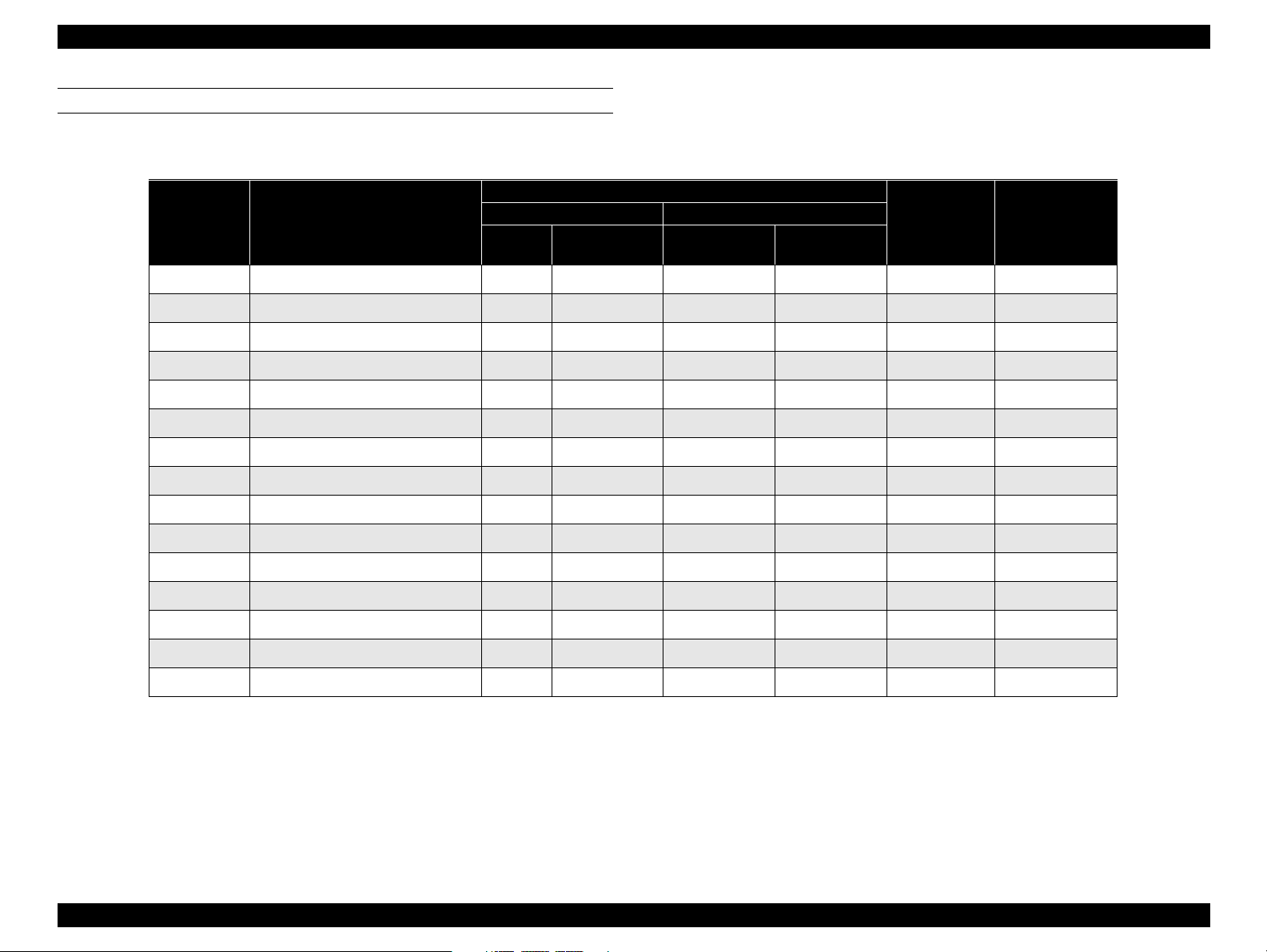
PAPER SIZE
Normal paper: See Table 1-5.
Table 1-5. Paper Size/ 2- UP Mode Availability
*1
A3W cassette
SEF Unavailable Unavailable
2UP mode
availability
*2
Duplex print
availability
Paper Size
MSI
A3W 328 x 453mm SEF
Paper setting orientation
Standard Option
Universal
casette
−−
500-Sheet/
LCP Unit
A3 297 x 420mm SEF SEF SEF
A4 210 x 297mm LEF LEF LEF
A5 148 x 210mm LEF
− − −
B4 257 x 364mm SEF SEF SEF
B5 182 x 257mm LEF LEF LEF
I-B5 176 x 250 LEF
−−−
LT 8.5 x 11” (215.9 x 279.4mm) LEF LEF LEF
HLT 5.5 x 8.5” (139.7 x 215.9mm) LEF
−−−
LG 8.5 x l4” (215.9 x 355.6mm) SEF SEF SEF
EXE
GLG 8.5 x 13” (215.9 x 330.2mm) SEF
GLT 8 x 10.5”(203.2 x 266.7mm) LEF
7.25 x 10.5” (184.15 x 266.7mm)
LEF LEF LEF
− − −
−−−
B (LD) 11 x 17” (279.4 x 431.8mm) SEF SEF SEF
F4 210 x 330 SEF
−−−
−
−
Unavailable Available
Available Available
Available Unavailable
−
−
Unavailable Available
Available Available
Available Unavailable
−
Available Available
Available Unavailable
−
−
Unavailable Available
Available Available
Unavailable Available
Available Available
−
Unavailable Available
Unavailable Available
*1: LEF: Long Edge Feed, SEF: Short Edge Feed
*2: 2UP is available only for paper size of LT(LEF) or smaller. For custom size paper, paper length along the loading direction must be 210 mm (8.5
inch) or shorter. As for envelopes, the total length with its flap opened must be 8.5 inch or shorter.
PRODUCT DESCRIPTIONS Specifications 1-6
Page 27
EPSON AcuLaser C8500 Revision B
Special paper: See Table 1-6
Table 1-6. Paper Size/2-UP Mode Availability
*1
A3W
cassette
2UP mode
availability
Available Unavailable
*2
Duplex print
availability
Paper Size
OHP Sheet
8.5 x 11”
(210 x 297mm)
Paper setting orientation
Standard Option
MSI
LEF
Universal
cassette
−−−
500-Sheet/
LCP Unit
Post Card 100 x 148 mm SEF
MON
C10
DL 110 x 220 mm LEF
C6 114 x 162 LEF
*1: LEF: Long Edge Feed, SEF: Short Edge Feed
*2: 2UP is available only for paper size of LT(LEF) or smaller. For custom size paper, paper length along the loading direction must be 210
mm (8.5 inch) or shorter. As for envelopes, the total length with its flap opened must be 8.5 inch or shorter.
*3: To feed envelope, open the flap and set it to the rear end.
37/8” x 71/2”
(98.43 x 190.54 mm)
41/8 x 91/2
(104.78 x 241.3 mm)
LEF
LEF
*3
*3
*3
*3
Paper aligning
Single side aligning (front side) for all sizes (both standard tray (MSI) and each
cassette)
Consumables
TONER CARTRIDGE (Black, Cyan, Magenta, Yellow)
DRUM CARTRIDGE (including one WASTE TONER BOX)
WASTE TONER BOX
− − −
−−−
− − −
−−−
− − −
Available Unavailable
Available Unavailable
Available Unavailable
Available Unavailable
Available Unavailable
REGULARLY REPLACED PARTS
MAIN FUSER ASSEMBLY (including an air filter)
PAPER OUTPUT
Face-down (FD):
250 sheets* (B5/EXE or larger, up to 105g/m
Face-up (FU):
150 sheets* (A4 or smaller)
50 sheets*
Applicable to the both single and duplex prints. (when recommended
*:
paper is used)
(larger than A4)
2
(28lb))
PRODUCT DESCRIPTIONS Specifications 1-7
Page 28
EPSON AcuLaser C8500 Revision B
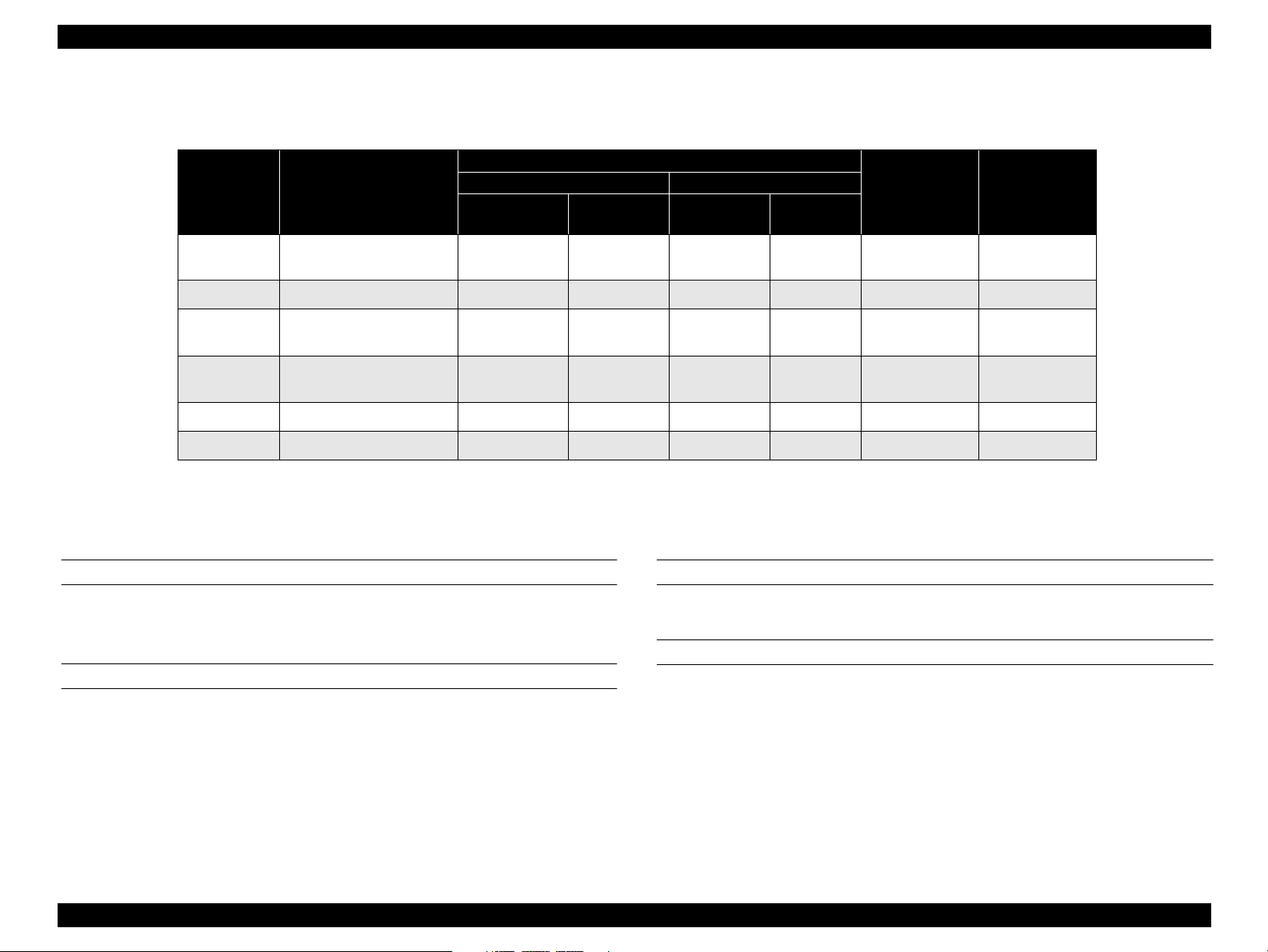
See Table 1-7 for FD output availability.
Table 1-7. Face-Down Output Availability
Paper Size FD Availability Paper Size FD Availability
A3W Available HLT Unavailable
A3 Available LG Available
A4 Available EXE Available
Normal paper
Special paper
NOTE:
1: The minimum paper size available for FD ejection is 182 mm in the paper feeding
direction x 210 mm vertical to the paper feeding direction.
2: “FU*” in the FD availability columns means face-up ejection for OHP, thick paper, and
envelope.
A5 Unavailable GLG Available
B4 Available GLT Available
B5 Available B(LD) Available
LT Available F4 Available
I-B5 Unavailable
OHP sheet FU* C10 FU*
Postcard FU* DL FU*
MON FU* C6 FU*
DIMENSIONS
Table 1-8. Dimensions
Description Dimension (W x D x H) mm
Printer
main body
Option
*1: Tolerance is +/- 1 mm.
*2: When the standard tray (MSI) and Output tray (FU) are stored.
*3: Printer dimensions with its optional units installed are given in Section
1.2.11 "Exterior View and Parts".
Standard condition
500-Sheet Paper Cassette
Unit
Large Capacity Paper Unit 578 x 602 x 264
A3W Cassette 560 x 547 x 95
*2 *3
650 x 646 x 554
With foot:575 x 602 x 164
With casters:575 x 602 x 206
WEIGHT
Table 1-9. Weight
Description Weight (kg +/- 1% kg)
Printer
body
Standard Condition 71.2
Duplex Unit 8.2
*1
With foot:13.3
With casters:14.0
NOTE:
500-Sheet Paper Cassette
Option
Unit
Large Capacity Paper Unit 21.2
A3W Cassette 2.7
Total weight after installing optional units is not a total sum of each
unit since their installation involves some part removal.
PRODUCT DESCRIPTIONS Specifications 1-8
Page 29

EPSON AcuLaser C8500 Revision B
VOLTAGE
110/120V version: 110V/120V ± 10%, 50/60Hz ± 3Hz
220/240V version: 220V/240V ± 10%, 50/60Hz ± 3Hz
POWER CONSUMPTION
Operating (color)*1:
Average:500Wh or less
Maximum:[100V/120V version]1000W or less (Fuser is on)
[220/240V version]1050W or less (Fuser is on)
Operating (B/W)*1:
Average:650Wh or less
Maximum:[100V/120V version]1000W or less (Fuser is on)
[220/240V version]1050W or less (Fuser is on)
Standby mode:
Average230Wh or less
Maximum900W or less (Fuser is on)
100W or less (Fuser is off)
Energy save mode*2:
RATED CURRENT
100 V version: 11A or less (at rated voltage)
115V version: 10A or less (at rated voltage)
240V version: 5A or less (at rated voltage)
Product life
Printer (including the standard tray):
Approximately 180,000* printed pages (450,000 images) on A4 LEF or five
years, whichever comes first.
* Note one full color print is formed with four images. So the printer can
prints 180, 000 sheets (=450,000 images) if its job ration between the
monochrome and color prints is 1:1. If the printer is used only for
monochrome print, it can prints 450,000 sheets (= 450,000 images =
90,000 x 4 + 90000)
500-Sheet Paper Cassette Unit:180,000 sheets
Large Capacity Paper Unit:180,000 sheets
Duplex Unit: 180,000 sheets (each side of paper is counted as
A3W Cassette: 180,000 sheets
.
one sheet)
Average160Wh or less
Maximum900W or less (Fuser is on)
100W or less (Fuser is off)
Low power mode*3:
Average30Wh or less
*1: Including the optional cassette unit and duplex unit.
*2:Saves more energy than the standby mode. The required for warming up is shorter.
*3:Full pause status. Conforms to the Energy Star program.
Acoustic noise
Printer only
Operating:54.8dB (A) or less
Stand-by:38.3dB (A) or less
Energy Save mode:38.3dB (A) or less
Lower power mode:35.0dB (A) or less
With the Duplex Unit and Large Capacity Paper Unit installed
Operating:59.4dB (A) or less
Stand-by:38.3dB (A) or less
PRODUCT DESCRIPTIONS Specifications 1-9
Page 30

EPSON AcuLaser C8500 Revision B
Energy Save mode:38.3dB (A) or less
Lower power mode:35.0dB (A) or less
Ozone density
0.01 ppm (time waited average value) or less.
TOXICITY
Photo conductor, toner, carrier, plastic material have no effect on human body.
DUST EMISSION
Dust concentration is less than 0.1 mg / m
3
PRODUCT DESCRIPTIONS Specifications 1-10
Page 31

EPSON AcuLaser C8500 Revision B
1.2.2 Paper Specifications
1.2.2.1 Paper Types
Recommended paper: 4200 paper (B/W), EPSON high quality normal
paper (For color sigle-side ohly), EPSON coated
paper,
Normal Paper: Normal copier paper, Recycled paper,
Special Paper: Exclusive OHP film, Postcard, Label, Color paper, Thick
NOTE 1:
NOTE 2:
lb: Ream Weight = lb/500sheets/17” x 22”
2
g/m
= 0.2659763 lb
1
Before purchasing a large amount of paper, try it out and check that it
is properly fed.
NOTE 3:
Avoid using the types of paper listed below to prevent abnormal
printing, paper jam, and printer malfunction.
• Carbon paper, non-carbon paper, thermal paper, impact paper, acidic paper
• Paper that has gone through a thermal or an ink-jet printer.
• Paper that is too thick or thin.
• Wet (damp) paper
• Paper to which a special coating has been applied, or colored paper that has gone
through surface process.
• Paper that has been lubricated (too smooth or slippery).
• Paper whose texture is different on the front and back.
• Paper with holes for binders and perforations.
• Paper with irregular shape or not cut with right angles.
• Paper with labels that come off and stick easily.
• Paper with glue, staples, or paper clips attached.
• Special ink-jet paper (Super Fine Paper, glossy film, and so on.)
• OHP sheets for other color laser printers, monochrome printers, and photocopiers.
• Paper that has gone through other color laser printers, monochrome printers, and
photocopiers.
• Pasted paper
2
64/m
- 105g/m2 (16lb - 28lb)
2
paper (105g/m
- 220g/m2), Envelope
1.2.2.2 Paper Source Classification
See Table 1-10.
RF
NOTE:
Standard tray (MSI) RF P RF
Standard universal cassette
A3W Cassette (option) RF P N N N N N
500-Sheet Paper Cassette Unit
Large Capacity Paper Unit
Duplex Unit*4
*1: 105 - 220g/m
*2: MON, C10, DL, C6
*3: Exclusive OHP sheet only
*4: Optional unit
: Reliable feeding and good image quality
P
: Possible, but limited to paper generally available
N
: Not supported
Table 1-10. Paper Usability for Each Paper Source
Special paper
paper
paper
Paper source
2
Normal
Recommended
RF P N N N N N
*4
*4
RF P N N N N N
RFPNNNNN
OHP sheet
*3
PPPP
Labels
Postcard
*1
Thick paper
*2
Envelope
PRODUCT DESCRIPTIONS Specifications 1-11
Page 32

EPSON AcuLaser C8500 Revision B
1.2.2.3 Printable Area
MAXIMUM PRINTABLE AREA
320 mm (12.6”) x 457.2 mm (18”)
MAXIMUM GUARANTEED PRINT AREA
Area with a margin of 4 mm from
each side.
Applied to paper size up to 297 mm
(11.7”) in width and 444.5 mm (17.5”)
in length.
4 mm
4 mm
Guaranteed
Guaranteed
print area
print area
4 mm
Figure 1-2.
Guaranteed Print Area
4 mm
1) Standard Tray (MSI) / A3W Cassette
330.2 mm
5 mm
4 mm
4 mm 431.8 mm
320 mm
457.2 mm
297 mm
Guaranteed
Guaranteed
print area
print area
Paper Feed
Direction
Printable area
Side guide is moved to this position for paper whose
Paper width is 304.8 mm (12”) or shorter:
From each edge
Paper width is longer than 304.8mm (12”)*:
From the point with a margin of 5mm.
* For paper whose width is more than 304.8 mm (12”), the side guide in
the MSI must be moved. So print start position changes to 5 mm from
the paper edge (a). This change also applies to A3W cassette. (See
Figure 1-3.)
PRODUCT DESCRIPTIONS Specifications 1-12
Maximum paper size: 330.2 mm (W) x 457.2 mm (L)
Printable area: 320 mm (W) x 449.2 mm (L)
Guaranteed print area: 297 mm (W) x 431.8 mm (L)
Figure 1-3. Printable Area - Standard Tray, A3W Cassette
width is more than 304.8 mm. (12.6 mm outward)
Side guide is here for paper whose width is
304.8 mm or less
Page 33

EPSON AcuLaser C8500 Revision B
2) Standard Universal Cassette
4
m
m
4 mm
457.2 mm
431.8 mm
304.8 mm
296.8 mm
Guaranteed
Guaranteed
print area
print area
4 mm
Paper Feed
Direction
3) 500-Sheet Paper Cassette Unit/Large Capacity Paper Unit
4 mm
431.8 mm
4
m
m
423.8 mm
304.8 mm
296.8 mm
Guaranteed
Guaranteed
print area
print area
Paper Feed
Direction
Side guide is here for paper whose
width is up to 304.8 mm
Maximum paper size: 304.8 mm (W) x 457.2 mm (L)
Printable area: 296.8 mm (W) x 449.2 mm (L)
Guaranteed print area: 296.8 mm (W) x 431.8 mm (L)
Maximum paper size: 304.8 mm (W) x 431.8 mm (L)
Printable area: 296.8 mm (W) x 423.8 mm (L)
Guaranteed print area: 296.8 mm (W) x 423.8 mm (L)
Side guide is here for paper whose
width is up to 304.8 mm
Figure 1-4. Printable Area - Universal Cassette
500-Sheet Paper Cassette Unit/Large Capacity Paper Unit
Figure 1-5. Printable Area -
PRODUCT DESCRIPTIONS Specifications 1-13
Page 34

EPSON AcuLaser C8500 Revision B
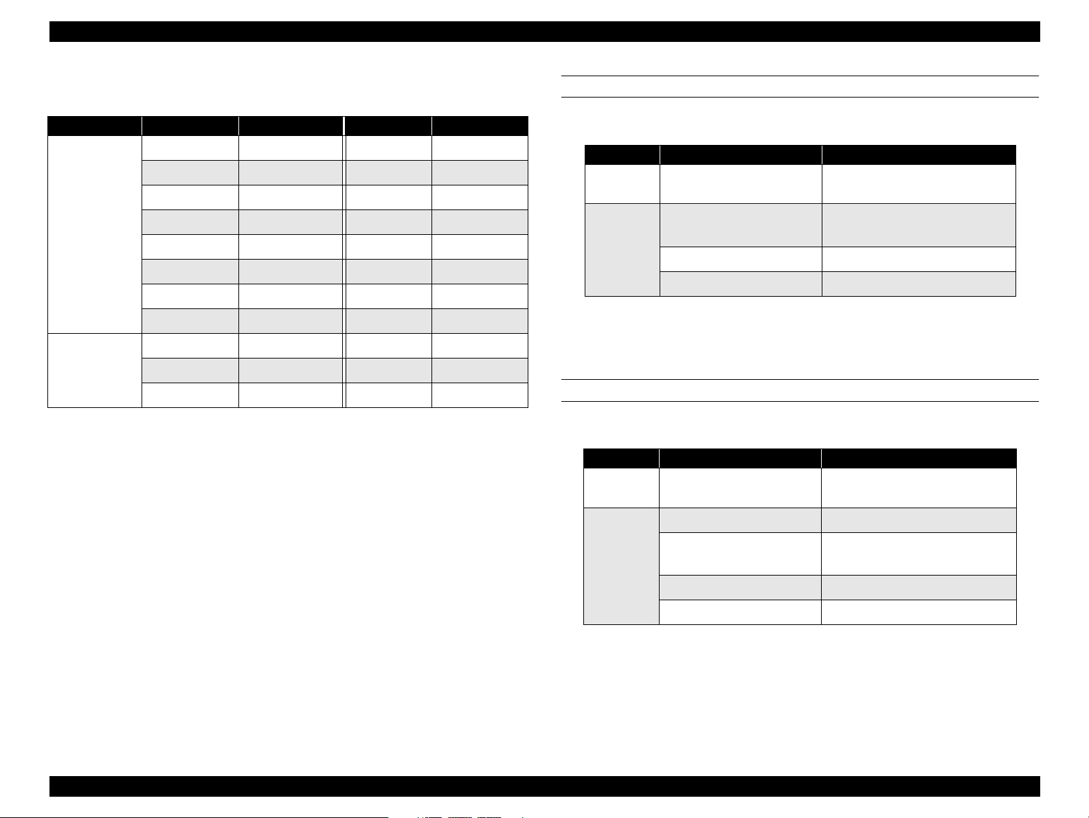
1.2.3 Reliability and Durability
Table 1-12. Standard Universal Cassette
MPBF
Including the standard tray (MSI): 60,000 pages or more*
Including the standard tray and Duplex Unit: 60,000 pages or more*
Including the 500-Sheet Paper Cassette Unit: 60,000 pages or more*
Including the Large Capacity Paper Unit: 60,000 pages or more*
*: = 150,000 images evaluated based on the MPBF in condition that the job ratio of the
color and monochrome prints is 1: 1, since 1 page of color print is formed with 4
images.
Rate
Paper jam rate
(single sided print)
Paper jam rate
(Duplex print)
Multiple feeding rate 1/800 or less 1/500 or less 1/25 or less
Recommended
paper
1/3000 or less 1/2000 or less 1/25 or less
1/1800 or less 1/1200 or less -
Normal paper Special paper
Paper feed reliability
See the following tables.
NOTE:
Paper jam or multiple feeding that occurs to the top sheet of an
additional paper stuck is ignored.
Table 1-11. Standard Paper Tray
Rate
Paper jam rate
(single sided print)
Paper jam rate (Duplex
print)
Multiple feeding rate 1/1000 or less 1/1000 or less 1/50
*1: Feeding reliability for envelopes is defined when printed on the front side
under a normal temperature only. (print on a back side is not guaranteed.)
Envelopes that are adherent due to high temperature are excluded.
Recommended
paper
1/1000 or less 1/500 or less 1/100
1/600 or less 1/300 or less -
Normal paper Special paper
Table 1-13. Optional 500-Sheet Cassette
Rate
Paper jam rate
(single sided print)
Paper jam rate (Duplex
print)
Multiple feeding rate 1/5000 or less 1/3000 or less 1/25
*1
Recommended
paper
1/5000 or less 1/3000 or less 1/25
1/3000 or less 1/1800 or less -
Normal paper Special paper
Table 1-14. A3W Cassette
Rate A3W Paper
Paper jam rate 1/2000
Multiple feeding rate 1/500
PRODUCT DESCRIPTIONS Specifications 1-14
Page 35

EPSON AcuLaser C8500 Revision B
PRINT POSITION ACCURACY
Main scan direction: Reference position (c) ± 2.5 mm
Sub scan direction: Reference position (a) ± 2.0 mm
See Figure 1-6.
a
c
b
Print AreaPrint Area
d
e
Figure 1-6. Print Position Accuracy
f
Paper Feed
Direction
MAINTAINABILITY
MTTR: Within 30 minutes (average) (95% is completed
within 50 minutes)
Curl height at ejection
Less than ± 15mm (Color printing with the image ratio of 5% in non- aligned
condition, which varies depending on the image rate and aligning pattern.)
PAPER SKEW
See Figure 1-6 and Table 1-15.
Table 1-15. Paper Skew
Direction A4 (landscape) A3
Main scan direction
(|c-d|)
Sub scan direction
(|a-b|)
±
1.5mm (f=196mm)
±
2.0mm (e=271mm)
±
3.0mm (f=406mm)
±
2.0mm (f=271mm)
PRODUCT DESCRIPTIONS Specifications 1-15
Page 36

EPSON AcuLaser C8500 Revision B
1.2.4 Operating Environment
TEMPERATURE/HUMIDITY
Temperature: 10 to 32
Humidity: 15% to 85% RH (without condensation)
HEIGHT
3100m or less
LEVELNESS
Front - rear direction on the table:5 mm or less (within 644 mm)
Right - left direction on the table:10 mm or less (within 560 mm)
LUMINOSITY
3000 lx or less (not to be exposed to direct sunlight)
°°°°
C
SURROUNDING ENVIRONMENT
Be sure to leave enough space around the printer for proper printer use and
operation. See Figure 1-7.
780 mm
Ventilation
150 mm
Ventilation
728 mm*
635 mm*
828 mm*
735 mm*
*1: With the Duplex Unit installed
*2: Standard condition
1
2
1
2
590 mm
435 mm
835 mm
Figure 1-7. Space Requirement
PRODUCT DESCRIPTIONS Specifications 1-16
Page 37

EPSON AcuLaser C8500 Revision B
1.2.5 Environmental Conditions for Storage and
Transportation and consumables)
TEMPERATURE AND HUMIDITY
Drop height:
Duplex Unit: 760 mm
500-Sheet Paper Cassette Unit: 760 mm
Large Capacity Paper Unit: 760 mm
A3W Cassette: 920 mm
Table 1-16. Temperature and Humidity
Condition Temperature Humidity
°
Normal condition 0 - 35
Extreme condition
*1: Without condensation
C 15 - 80%RH For 12 months
High: 35 - 40 °C
Low: -20 - 0
°
C
High: 80 - 95%RH
Low: 5 - 15%RH
*1
Guaranty
1 month (Max.)
STORAGE AIR PRESSURE (ALTITUDE)
0 - 3100 meters (0 up to 15000m is possible during air shipping, but the air
pressure in the cargo room must be 70.9275 KPa or more.)
DROP TEST
Printer main body
Free drop
Height: [Bottom] 457 mm (18”)
[Other than bottom] 305 mm (12”)
Test times: [Bottom] Once
[Other than bottom] Once for each face
(total 5 faces)
Resistance to vibration
Frequency: 2 - 500 Hz
Acceleration: 12.6 m/s2 (on the vibration board) *
Direction: Three directions
X, Y: Vertical
Z: Horizontal
Duration: 50 minutes
*: Overall rms value
Edge drop
Height: 457 mm (18”)
Test times: Once for each edge (Total 4 edges)
Optional units
Test method: 1 corner, 3 edges, 6 surfaces
PRODUCT DESCRIPTIONS Specifications 1-17
Page 38

EPSON AcuLaser C8500 Revision B
1.2.6 Electrical Specifications
Specifications here are not applicable to any optional units.
AC line noise
Pulse width: 50 to 1000 ns
Pulse polarity: +/-
Repeat: Not synchronized
Modes: Common/normal
Voltage: 1kv (However, the parts can withstand up to
2kv without damage.)
Instant cutoff
DIP amount: 100% (at rated voltage -10% and rated
frequency -10%) for one cycle with normal
print quality.
Electrostatic durability
No possibility of any error which affects on print quality under the following
conditions.
Dielectric strength
There is no breakdown when the following voltages are applied for
one minute.
100V/120V model:
AC 2000V (Between primary and secondary sides)
AC 1000V (Between primary side and chassis)
220V/240V model:
AC 2000V (Between primary and secondary sides)
AC 1500V (Between primary side and chassis)
Leakage current
100V version: 0.25 mA or less*
120V version: 3.5 mA or less*
220/240V version: 3.5 mA or less*
*: Condition:1.5K W , 0.15µ F (between frames and non-charged
metallic parts)
Atmospheric discharging:
Contact discharging:
±
±
8KV
6KV
Rush current
1/2 cycle, 100A or less, 10 msec or less
Insulation resistance
10M Ω or more
PRODUCT DESCRIPTIONS Specifications 1-18
Page 39

EPSON AcuLaser C8500 Revision B
1.2.7 Process Specifications
Printing method: Dry electrophotographic with 2 ingredients Using
the intermediate belt transfer system
Light source: Semi-conductive laser beam
Exposed object: OPC drum (organic photo conductor)
Charging method: Roller transfer system
Developing method: Exposed part developing system
Toner: Single-ingredient nonmagnetic toner with carrier
1st transfer: Intermediate belt transfer system
2nd transfer: Roller transfer system
Fusing: Heat roller system
Density adjustment: Automatic (can not be set by user)
1.2.8 Applicable Standards
SAFETY STANDARDS
100V/120V version: UL1950 3rd Edition
CSA C22.2 No. 950-M95
220V/240V version: IEC950 2nd Edition
EN60950
A3 by VDE with GS-mark
EMI
US: FCCPart15 SubpartB, ClassB(ANSI 63.4/11.4D)
Europe: EN55022(CISPR Pubilication22), ClassB
Also, the printer main body meets the following
standards:
EN61000-3-2 (Hamonics)
EN61000-3-3 (Flicker)
POWER SUPPLY HARMONIC
Meets the power supply harmonic control guide line.
CONSUMPTION CURRENT
Conforms to the International Energy Star Program (30W or less in the low
power mode)
(Conforms to 30W or less in the low voltage mode (International Energy Star
Program Draft 3). Main body: 15W or less. Controller: 5V 2.5A 15W)
OTHERS
Toner: No effect on human health (OSHA, TSCA,
EINECS)
Carrier: No effect on human health
OPC: No effect on human health (OSHA)
SAFETY REGULATIONS (LASER RADIATION)
100V/120V version: FDA21CFR Chapter 1, Subchapter J, Section
1010, 1040
220V/240V version: IEC825 Class I Laser Product
NOTE:
Laser power:5mW (rated)
Wave length: 785nm +15/-15nm (at 25
°
C)
Ozone: UL478 (5th edition)
Material: SWISS environmental law (must contain no Cds)
PRODUCT DESCRIPTIONS Specifications 1-19
Page 40

EPSON AcuLaser C8500 Revision B
1.2.9 Options and Consumable Products
The following tables list the options and consumable products for AcuLaser
C8500.
NOTE:
The asterisk at the end of each product code is a substitute of the
last digit of the product code, which varies by county.
Table 1-17. Options
Product Code Remarks
Large Capacity Paper Unit C813501*
Holds two 500-sheet
paper cassettes
Toner Cartridge (Yellow) S050039
Toner Cartridge (Magenta) S050040
Toner Cartridge (Cyan) S050041
Toner Cartridge (Black) S050038
Waste Toner Collector (WASTE TONER BOX) S050020
Photoconductor unit (DRUM CARTRIDGE) S051073
Table 1-18. Consumable Products
Product Code
500-Sheet Paper Cassette Unit C813511*
250-Sheet Paper Cassette A3W C813521*
Duplex Unit C813531*
Hard Disk Drive C823771*
Adobe PostScript 3 Kit C832431*
EPSON RIP Station 5300 C850142*/850143*
Color Copy Station 8500
32KB Serial Interface Card C82307*
32KB Parallel Interface Card C83610*
Coax Interface Card C82314*
Twinax Interface Card C82315*
GPIB Interface Card C82313*
10 Base T/100 Base TX C82363*
10 Base 2/10 Base T C82362*
IEEE1394 C82372*
Holds one 500-sheet
paper cassette
EPSON Color Laser Paper (A4) S041215
EPSON Color Laser Paper (A3) S041216
EPSON Color Laser Paper (A3W) S041217
EPSON Color Laser Paper (Letter) S041218
EPSON Color Laser Transparencies (A4) S041175
EPSON Color Laser Transparencies (Letter) S041174
EPSON Coated Paper (A4) S041383
EPSON Coated Paper (A3) S041384
PRODUCT DESCRIPTIONS Specifications 1-20
Page 41

EPSON AcuLaser C8500 Revision B
TONER CARTRIDGE SPECIFICATIONS
NOTE:
Toner cartridges for the AcuLaser C8500 and EPL-C8000/8200
are not compatible.
Toner Cartridge life
See Table 1-19.
Table 1-19. Toner Cartridge Life
Item Life
Toner Cartridge (Black) 5,500 images
Toner Cartridge (Cyan) 6,000 images*
Toner Cartridge (Magenta) 6,000 images*
Toner Cartridge (Yellow) 6,000 images*
*1: Defined under the conditions that the image ratio is 5% on A4 (LEF)
paper during continuous printing, and different in color printing. Also,
life varies depending on the image ratio and printer usage, weather
continuous or intermittent.
Dimensions and weight
Unpacked
Dimensions (W x H x D): 50 mm x 400 mm x 54.5 mm
Weight: K 0.371 kg
Y/M/C 0.370 kg
Packed
Dimensions (W x H x D): 85 mm x 435 mm x 80 mm
Weight: K 0.474 kg
Y/M/C 0.473 kg
NOTE:
Tolerance for the dimension and weight is +/- 1%.
Environmental conditions for storage and transportation
Temperature/Humidity: See Table 1-20.
*1
Table 1-20. Temperature/Humidity
Temperature Humidity
Normal
condition
Extreme
condition
*1: Without condensation
*2: 12 months for unpacked cartridge under the used condition.
Storage air pressure (altitude)
°
C 15 - 80% RH 24 months
0 - 35
High: 35 - 45 °C
°
Low: -20 - 0
C
High: 80 - 95% Rh
Low: 5 - 15% Rh
0 - 3,100m (0 up to 15,000 m is possible during air shipping, but the air
pressure in the cargo room must be 70.9275KPa or more.)
Drop test (packed):
Height: 91 cm
Test method: 1 corner, 3 edges, 6 surfaces
Resistance to vibration (packed):
Frequency: 5 - 100 Hz
Acceleration: 6.9m/s
2
Direction: 3 directions (X, Y, Z)
Duration: 50 minutes (single way) for each direction
*1
PHOTOCONDUCTOR UNIT SPECIFICATIONS
NOTE:
Toner Photoconductor unit for the AcuLaser C8500 and EPLC8000/8200 are not compatible.
Formation: PHOTOCONDUCTOR
DRUM CLEANER
WASTE TONER BOX
Life:
Dimension and weight*
Unpacked
20,000 sheets*1 (The waste toner box has the same life)
2
Guaranty*21
1 month (Max.)
Dimension (W x D x H) : 213 mm x510 mm x 181 mm
Weight: 2.4 kg
PRODUCT DESCRIPTIONS Specifications 1-21
Page 42

EPSON AcuLaser C8500 Revision B
Packed
1.2.10 Regularly Replaced Parts
Dimension (W x D x H) : 318 mm x 618 mm x 280 mm
Weight: 3.5 kg
Environmental condition for storage and transportation
MAIN FUSER ASSEMBLY (including an air filter) 100,000 sheets
Same as for the toner cartridge
*1: Defined under the conditions that the image ratio is 5% on A4 (LEF) paper during
continuous printing, and different in color printing. Also, life varies depending on
the image ratio and printer usage, weather continuous or intermittent printing.
*2: Tolerance for both dimension and weight is ± 1%
WASTE TONER BOX SPECIFICATIONS
NOTE:
Waste Toner Boxes for the AcuLaser C8500 and EPL-C8000/8200
are compatible.
Formation:
Life: 20,000 sheets*
Dimension and weight*
Unpacked
2
WASTE TONER BOX and others
1
Dimension (W x D x H) : 75.5 mm x 444 mm x 131 mm
Wight: 0.45 kg
Packed
Dimension (W x D x H) : 149 mm x 495 mm x 192 mm
Weight: 0.87 kg
Environmental condition for storage and transportation:
Same as for Toner Cartridge
*1:Defined under the conditions that the image ratio is 5% on A4 (LEF) printing at 4P/J.
Life varies depending on the image ratio and printer usage, weather continuous or
intermittent printing.
*2:Tolerances for dimensions and weight are both ± 1%
PRODUCT DESCRIPTIONS Specifications 1-22
Page 43

EPSON AcuLaser C8500 Revision B
1.2.11 Exterior View and Parts
The table below lists the major exterior parts names. For the corresponding
location, see the following figures. Note if any part names differ from the
descriptions in the User’s Guide, they are shown in the brackets.
Table 1-21. Exterior View and Parts
Part name Part Name
a Control Panel s Ethernet I/F connector
Cover A / EXIT UPPER COVER
b
(Output path cover)
c STOPPER COVER (Stopper) u
d FRONT COVER v Paper cassette 2 / LC2 (Option)
e Face-Up Tray w Paper cassette 3 / LC3 (Option)
f Standard tray/MSI Tray/MP Tray x Cover E / FEEDER CHUTE ASSY
Standard Universal Cassette
g
(Standard lower cassette)
h RIGHT COVER z INVERTER ASSY
Unit C / MSI ASSY
i
(Paper path unit)
Mounting screw hole for EPSON
t
RIP Station 5300
FRONT MID COVER
(Duplex unit slot cover)
y Unit B / DUP TRANSPORT ASSY
A Cover F / INVERTER ASSY
Table 1-21. Exterior View and Parts
Part name Part Name
Cover D/TURN CHUTE COVER
p
(Paper cassette cover)
q Filter Assy I 500-Sheet Paper Cassette Unit
Option slot cover (for EPSON RIP
r
Station 5300)
H Logo Plate
- -
j Parallel I/F Connector B Unit G / DUPLEX UNIT
k Ground screws C
l Interface card slot cover D INVERTER ASSY Connector
m Power switch E
n AC inlet F Connector
o Fuser unit/Unit B G Large Capacity Paper Unit
DUP TRANSPORT ASSY
Connector
Large Capacity Paper Unit
Connector
Figure 1-8. Exterior Parts - Top View
PRODUCT DESCRIPTIONS Specifications 1-23
Page 44

EPSON AcuLaser C8500 Revision B
Front View
Right View
Back View
Left View
Figure 1-9. Exterior Parts - Printer Main Body
PRODUCT DESCRIPTIONS Specifications 1-24
Page 45

EPSON AcuLaser C8500 Revision B
Front View
Right View
Left View
Back View
Figure 1-10. Exterior Parts - Options
PRODUCT DESCRIPTIONS Specifications 1-25
Page 46

EPSON AcuLaser C8500 Revision B
1.2.12 Controller Specifications
Front View
Right View
CPU
R5000 (266MHz)
ENHANCEMENT TECHNOLOGIES
AcuLaser Color Halftoning (B/W supported)
RIT, CRIT
RAM
SDRAM:
64-bit-wide DIMM (168-pin, 3.3V)
Maximum: 768MB (when a 256MB ROM is installed instead of the
standard RAM. With the standard RAM used, the maximum memory
size is 576MB.)
3 RAM slots, including 1 for standard RAM
Standard: 64MB
Expansion: 32MB, 64MB, 128MB, 256MB
ROM
32-bit-wide
Program: 4MB (ROM DIMM)
Font: 4MB
EXPANSION ROM
3 slots (ROM DIMM slots)
Slots A, B: Font ROM module, PostSccipt3 module, EPSON
RIP Station 5300 module, CM table
Slot C: Exclusively used for NLSP Font ROM module
PRODUCT DESCRIPTIONS Specifications 1-26
Page 47

EPSON AcuLaser C8500 Revision B
PANEL
1-line 20-character LCD, 6 LEDs, 8 buttons
Optional: Postscript3 (PostScript3 module, Peacock-B)
Others: EJL mode, PJL mode, RCC mode, DIAG mode
SUPPLEMENTARY SOFTWARE:
INTERFACES
Status sheet
Standard:
Parallel 1ch
1EEE-1284-compliant bidirectional
B-type connector
Compatibility
Nibble
ECP
Ethernet 100Base/TX, 10Base/T 1ch
Optional:
Type-B - 1 slots (for level 3)
EPSON RIP Station 5300 interface - 1 slot (exclusive)
Network Status Sheet
Option I/F Status Sheet*
PS3 Status Sheet*
Font Sample (each mode)
Hex dump
Support mode
Maintenance mode (Engine Status Sheet, for engine)
*1:
Only when Type-B level 3 is installed.
*2:
Only when a PostScript3 module is installed.
1
2
RTC
Timer function (for job management)
HDD
1 (option)
PRINTER SETTINGS
Made through the panel setting mode, EJL commands, and MIB
PRINTER MODES
Standard: ESC/Page-Color, ESC/Page (B/W), LJ4 mode,
GL2 mode, ESCP2 mode, FX mode (B/W), 1239X
mode (B/W)
INSTALLATION
Installed to the main printer body.
1.2.13 Controller Configuration
The controller board configuration of this printer can be set for the target
market (destination) as indicated below. The settings are made at factory (by
jumper resistor).
The factory default setting for the paper size (A4 or Letter)
For North and South America:Letter
For Europe, the Pacific / Russia, Taiwan, China and Korea: A4
The default paper size (EXE or B5) for paper cassette
For North and South America, Europe, and the Pacific/Russia : EXE
For Taiwan, China and Korea: B5
PRODUCT DESCRIPTIONS Specifications 1-27
Page 48

EPSON AcuLaser C8500 Revision B
1.3 Interface Specifications
The AcuLaser C8500 supports the following external interfaces.
Standard: 1. Parallel interface
2. Ethernet interface
Optional: Type-B host interfaces (1 slot)
By installing the I/F board for EPSON RIP Station 5300, EPSON RIP Station
5300 panel and scanner interface are equipped.
TypeB
(AUX)Interface
EPSON RIP
Station 5300
Interface
Figure 1-11. Host Interface Slots
Parallel Interface
(IEEE1284 B-Type)
LED: Link/
Receive Lamp
LED: 100Base/
10Base Lamp
Ethernet Interface
(100BaseTX/10BaseT
1.3.1 Parallel Interface Specifications
INTERFACE TYPE
IEEE 1284 High-Speed Bi-directional Parallel I/F
OPERATING MODES
Compatibility, Nibble, ECP
SYNCHRONIZATION
/STROBE pulse
CONNECTOR TYPE
57RE-40360-830B(D7A)DDK or equivalent
PLUG
Amphenol equivalent
DATA TRANSMISSION TIMING
Refer to Table 1-22 and Figure 1-12.
PIN ASSIGNMENT
Refer to Table 1-24.
PRODUCT DESCRIPTIONS Interface Specifications 1-28
Page 49

EPSON AcuLaser C8500 Revision B
Table 1-23. Centronics Parallel Interface Pin Assignment
Table 1-22. Data Transmission Timing
Min. Typ. Max
(1) Data hold setup 0.5 us
(2) Data hold 0.5 us
(3) Strobe pulse 0.5 us
(4) BUSY to STRBX 0 us
(5) STROB to BUSY 0.5 us
(6) BUSY to STRBX 0 us
(7) ACKX pulse width 0.5 us 1 us*
(8) ACKX to BUSY 0 s
(9) BUSY to PE or ERRX 2 ms*
(10) PE or ERRX to BUSY 2 ms*
(11) Power on to signal output valid 05 s
(12) PE or ERRX to ACKX 2 ms*
(13) STRBX to ACKX 0 s*
Pin # Signal Names I/O Descriptions
1STRBXI
Latch pulse used to read data. DATA is valid
when the signal is LOW.
2-9 DATA 1-8 I DATA 8 is MSB and DATA 1 is LSB.
An acknowledge pulse to the host that indicates
10 ACKNLGX O
the data from the host computer has been
received.
11 BUSY O
12 PE O
HIGH status indicates the printer is not ready to
accept data.
Indicates paper empty status in paper tray or
cassette selected.
13 SELOT O Always HIGH.
When the signal is LOW, the printer automatically
feeds a line as “CR” is input. The “CR” is detected
14 AUTOX I
when the printer is turned on or the interface
selection is switched from the optional I/F to
parallel I/F.
15 NC - Not used.
16 GND - Ground level for the twisted pair return.
Connected to the printer chassis. The printer
DATA
STRBX
VALID
1
VALID
3
VALID
VALID
2
17 CG -
18 NC - Not used.
chassis GND and the signal GND are connected
each other.
19-30 GND - Ground level for the twisted pair return.
BUSY
ACKX
31 INITX I
8
6
8
6
7
When the signal is LOW, the STRBX signal is
ignored.
The signal is LOW when the printer is in the
following condition:
Figure 1-12. Data Transmission Timing
32 ERRX O
1) User maintenance is required. 2) Service
maintenance is required. 3) Another type of error
has occurred. 4) The printer is off line.
33 GND - Ground level for the twisted pair return.
PRODUCT DESCRIPTIONS Interface Specifications 1-29
Page 50

EPSON AcuLaser C8500 Revision B
Table 1-23. Centronics Parallel Interface Pin Assignment
Pin # Signal Names I/O Descriptions
34 NC - Not used.
35 +5V - Pulled up to +5V through 1K Ω resistor.
36 SELINX I Always LOW.
DEVICE ID
1
✝✝✝✝
**
;
MFG:EPSON;
CMD:PJL,EJL,ESCPL2,ESCP9,PRPXL24-01,PCL,HPGL201,ESCPAGE-04,ESCPAGECOLOR-01**
3
MDL:**
✝✝✝✝
;
CLS:PRINTER;
4
DES:EPSON **
1: The hexadecimal value of the “total number of characters +2” of the
=
✝✝✝✝
;
device ID is entered.
†2: ”POSTSCRIPT” is added only when the PostScript 3 module is
installed.
†3: Displays model name AL-C8500
†4: Manufacturer and model name are displayed EPSON AL-C8500
Note the MFG, MDL, DES, and CID can be defined by the users. The CID field,
which does not reply at initialized device ID, only replies with a user-defined
character string. The device ID at re-definition is as shown below. A “*****”
represents a user-defined character string.
MFG:*****;
CMD:PJL,EJL,ESCPL2,ESCP9,PRPXL24-01,PCL,HPGL201,ESCPAGE-CMD:PJL,EJL,ESCPL2,ESCP9,PRPXL2401,PCL,HPGL2-01,ESCPAGE-04,ESCPAGECOLOR-01**
MDL:*****;
CLS:PRINTER;
DES:*****;
CID:*****;
2
✝✝✝✝
;
2
✝✝✝✝
;
1.3.2 Ethernet Interface
INTERFACE TYPE
10BaseT, 100BaseTX, Half Duplex, Full Duplex (Switched at power on)
COMMUNICATION PROTOCOL
1. IPX/SPX (IPX, SPX, NCP, RIP, SAP, PrintServer, RemotePrinter, NDS,
SNMP, ENPC)
2. NetBIOS (SMB)
NetBEUI
3. TCP/IP (IP, UDP, TCP, LPR, FTP, TELNET, ARP, ICMP, RARP, BOOTP,
DHCP, SNMP, HTTP, ENPC)
4. AppleTalk (ELAP, DDP, ATP, PAP, AARP, NBP, ZIP, RTMP, SNMP,
ENPC)
CONNECTOR TYPE
RJ45
APPLICABLE CABLE
2-pair STP (10BaseT, 100BaseTX)
NOTE:
PIN CONFIGURATION
See Table 1-24.
Use a shielded cable (category 5) to meet FCC Class B, VCC
class B.
PRODUCT DESCRIPTIONS Interface Specifications 1-30
Page 51

EPSON AcuLaser C8500 Revision B
1.3.3 Type B Interface
Table 1-24. Pin Configuration for the Ethernet I/F
Pin Signal Name I/O
1Tx+ O
2 Tx- O
3Rx+ I
4 N.C. -
This printer is equipped with a slot for Type B optional interface.
MAIN SYSTEM TYPE
MTP600dpi,PW7748dt600dpi,PRG(*****)rev.AP1300ma,SPD0fast,D4
∗ ∗ ∗ ∗ ∗
NOTE:
“
“ represents a ROM version.
5N.C. -
6 Rx- I
7N.C. -
8 N.C. -
ENTITY TYPE
See Section 1.3.3 "Type B Interface".
PRINTER NAME
Same as the product name when shipped from the factory.
PRODUCT NAME
Brand Name: AL-C8500
OEM Name: ESC/Page Printer
EMULATION TYPE/ENTITY TYPE
Table 1-25. Emulation Type/Entity Type
Emulation Emulation Type Entity Type
*1
PS
ESC/Page Color ESCPAGECOLOR-01 EPSONPAGECOLOR1
ESC/Page ESCPAGE-04
LJ4 PCL5E-00 EPSONPCL5
1239X PRPXL2-01 EPSONPRPXL24
GL2 HPGL24-01 EPSONHPGL2
POSTSCRIPT-00
*1
LaserWriter
*1
FX ESCP9 EPSONFX
ESCP2 ESCPL2 EPSONLQ2
*1: Added when a PostScript3 module is installed.
PRODUCT DESCRIPTIONS Interface Specifications 1-31
Page 52

EPSON AcuLaser C8500 Revision B
Emulation type
Emulation = AUTO
1) When PS is not started :AUTO (Emulation Types 1, 2, 3 . . .)
1.4 Control Panel
This section describes the control panel of this printer and its functions.
Entity Type
2) When PS is started : EJL (POSTSCRIPT-00, other Emulation
Types 1, 2, 3 . . .)
Emulation = Fixed
EJL (Default Emulation Type, other Emulation Types 1, 2, 3, . . .)
Emulation = AUTO
See Table 1-25.
Emulation = Fixed
The Default Emulation Type and EPSONPAGECOLOR1 are returned.
Continue
Continue
(D) (E)
(A) (B)
On Line
On Line
(C)
Form Feed
Form Feed
(H) (I) (J) (K) (L) (M) (N) (O)
Reset
Reset
Figure 1-13. Control Panel Appearance
1.4.1 Appearance and Descriptions
The control panel of this printer consists of the LCD, 8 buttons, and 6 LEDs.
See Figure 1-13 and Table 1-26 for the control panel appearance and its
descriptions, respectively.
(F)
(G)
Paper Source Paper Size Manual Feed Orientation
SelecType
SelecType
Alt
Alt
Paper Source Paper Size Manual Feed Orientation
RITech
RITech
Menu Item Value
Menu Item Value
Copies MP Tray Size
Copies MP Tray Size
Toner Save
Toner Save
Mode
Mode
Enter
Enter
Table 1-26. LEDs and switches on the Control Panel
LED Button
Location Name Remarks Location Name Remarks
A LCD Panel
1 line, 20 characters (5 x 7 dot
matrix)
H On Line button
B On Line LED Green I Form Feed button
C Data LED Yellow J Continue button
PRODUCT DESCRIPTIONS Control Panel 1-32
Page 53

EPSON AcuLaser C8500 Revision B
Table 1-26. LEDs and switches on the Control Panel
LED Button
Location Name Remarks Location Name Remarks
D Continue LED Red K SelecType/Alt button Also serves as the Shift button
E OneTouch Mode 2 LED L Menu Select button
F OneTouch Mode 1 LED M Item Select button
G SelecType Mode LED N Value Select button
- - O Enter button
PRODUCT DESCRIPTIONS Control Panel 1-33
Page 54

EPSON AcuLaser C8500 Revision B
1.4.1.1 LED Description
LCD (Liquid Crystal Display) (A)
One-line display for 20 characters (5 x 7 dot matrix)
Normally displays printer status. In panel setting mode, LCD displays various
setting values.
On Line LED (B)
On: The printer is on-line.
Off: The printer is a pause status.
Form Feed LED (C)
On: Unprinted data remains in the printer. However, the lamp is not
lit if the remaining data is not effective print data but other data
such as control codes including commands.
Off: No effective print data remains in the printer. If control codes
are not terminated, the indicator lights up.
Blinking: The printer is processing data.
Continue LED (D)
Blinking: An error has occurred which can be cleared by pressing the
Continue button.
OneTouch Setting Mode 1 LED (E)
OneTouch Mode 2 LED (F)
On: OneTouch mode 2 is enabled. The following 4 items can be
set in this mode:
“RITech”, “Copies”, “Mp Tray Size”, “Toner Save Mode”
SelecType Mode (G)
On: SelecType mode is enabled.
All LEDs
All LEDs come on when a service-call error has occurred.
1.4.2 Button Functions
On Line button (H)
When the printer is on-line, pressing this button puts the printer in off-line to
prevent printing. Pressing this button during panel setting mode immediately
terminates the setting mode and brings the printer back to on-line status.
Form Feed button (I)
If the Form Feed lamp is lit in off-line status, pressing this button causes the
printer to print a page of data. If data for multiple pages has been received, it is
printed. If the Form Feed LED is lit because the control codes are not
terminated, data received up to that point is printed. The printer does not eject
paper when the Form Feed LED is on.
On: OneTouch mode 1 is enabled. The following 4 items can be
set in this mode:
“Paper Source”, “Paper Size”, “Manual Feed”, “Orientation”
Continue button (J)
While the Continue LED is on, pressing this button clears the error. Also, a
warning message indicated during on-line status can be cleared by pressing
this button.
PRODUCT DESCRIPTIONS Control Panel 1-34
Page 55

EPSON AcuLaser C8500 Revision B
SelecType button (K) (or Shift button)
Used to select OneTouch mode 1 / OneTouch mode 2 / SelecType mode, as
follows:
The first push of the button puts the printer in OneTouch mode 1.
Pressing this button in the OneTouch mode 1 puts the printer in OneTouch
mode 2.
Pressing this button in the OneTouch mode 2 activates the SelecType
mode to enter the initial level of SelecType mode. (The “Test Menu”
appears.)
Menu button (L)
Pressing this button activates the SelecType mode. The initial level of the
mode (“Test Menu”) appears. In the SelecType mode, this button is used
to select the setting menu, the primary level of the mode.
In OneTouch mode 1, used to select the value for “Paper Source”.
In OneTouch mode 2, used to select the item for “RITech”.
In SelecType mode, used to select the setting menu.
NOTE:
If this button is pressed with the Shift button held down, setting
values and items scroll backward.
Value button (N)
Pressing this button enables the item that was last selected.
In OneTouch mode 1, used to select the value for “Manual Feed”.
In OneTouch mode 2, used to select the value for “MP Tray Size”.
In SelecType mode, used to select the value for the currently selected
setting item. The next available value for the item is indicated.
NOTE:
If this button is pressed with the Shift button held down, setting
values and items scroll backward.
Enter button (O)
Pressing this button generates “Status Sheet” in “Test Menu”.
In OneTouch mode 1, used to select the value for “Orientation”.
In OneTouch mode 2, used to select the value for “Toner Save Mode”.
In SelecType mode, the setting value is confirmed and printing or other
functions are activated.
NOTE:
If this button is pressed with the Shift button held down, setting
values and items scroll backward.
Item button (M)
Pressing this button brings up the item that was last selected.
In OneTouch mode 1, this button is used to select the value for “Paper
Size”.
In OneTouch mode 2, this button is used to select the value for “Copies”.
In SelecType mode, this button is used to select the setting item.
NOTE:
If this button is pressed with the Shift button held down, setting
values and items scroll backward.
Reset button (Continue button + Alt button) (K + J)
Pressing this button with the Alt button held down causes the printer to stop
printing and reset. After the message “Reset” is indicated on the LCD, if the
both buttons are kept pressed for more 5 seconds, “Reset All” is indicated and
warm boot is performed.
PRODUCT DESCRIPTIONS Control Panel 1-35
Page 56

EPSON AcuLaser C8500 Revision B
1.5 Service Functions
Turning the printer on while pressing the specified button(s) until RAM check is
completed provides several service functions. The service functions supported
with this printer and corresponding activation methods are as listed below.
Table 1-27. Service Functions
Function Operating Method
Hex Dump
Support Mode
EEPROM Initialization
Panel Setting Value
Initialization
Format Flash ROM Module
Program ROM Update
ROM Module Copy
Maintenance Mode
Engine program ROM
update
CPU reset when a Service
Call occurs.
Printing of the Error Sheet
Turn on the power while pressing the
Feed
button.
Turn on the power while pressing the
button.
Turn on the power while pressing the
Continue
+
Turn on the power while pressing the
Continue
Turn on the power while pressing the
Item
Turn on the power while pressing the
+
Turn on the power while pressing the
+
Turn on the power while pressing the
+
Turn on the power while pressing the
+
When a Service Call Error occurs, Press the
Alt
Following CPU Reset after a Service Call Error
occurs, press the
Val u e
+
Alt
Value
+
Alt
Enter
+
Form Feed
Alt
Item
+
Menu
+
Menu
+
button.
+
buttons.
buttons.
+
Val u e
+
Item
+
buttons.
Enter
buttons.
Continue
buttons.
Value
+
Enter
buttons.
+
button
Enter
2 times.
Form
Value
On Line
Alt
+
On Line
On Line
On Line
On Line
buttons.
1.5.1 Hex Dump Mode
Buttons: Form Feed + Power on
Functions: “Hex Dump” is indicated. Received data is converted into
hex ASCII. This is valid for all interfaces. The hex damp
sheet contains the following information:
Dump list with the received data in hex ASCII format
Data list with 1-byte code characters (Unreadable
characters are expressed by *.*.)
Page number
Termination:Press “Reset” button to perform warm boot
or turn the printer off and back on.
1.5.2 Support Mode
Buttons: Value + Power on
Functions: Adds the support mode to the setting menu list. Once it is
added, the printer performs warm-boot, then the support
mode can be selected and executed. The support mode
enables servicers to set items, including HDD initialization,
that are normally not set by the users.
NOTE:
By using the Support Mode, this printer can adjust the 2nd Bias
Transfer Voltage at the user’s level. See 1.6.3.6 "Toner Transfer
Menu" for detail.
1.5.3 EEPROM Initialization
Buttons: On Line + Continue + Menu + Power on
Functions: Clears the EEPROM to 00h and writes factory default
values. In this printer, however, the Fuser counter and
Total pages are not cleared by this operation. Color pages
is cleared. (Color Pages is stored in the controller. The
fuser counter and Total Pages are stored on the engine
side.)
Termination: After initializing, the printer performs warm boot and
returns to the normal states.
PRODUCT DESCRIPTIONS Service Functions 1-36
Page 57

EPSON AcuLaser C8500 Revision B
1.5.4 Panel Setting Value Initialization
Buttons: Continue + Power on
Functions: All panel settings for total environment and interface-
specific environment are reset to the factory defaults.
Information such as accumulated printed pages to which
users have no access is not initialized.
Termination: After initializing, the printer performs warm boot and
returns to the normal states.
1.5.5 Formatting the Flash ROM Module
Buttons: Alt + Item + Value + Enter + Power on
Functions: Clears the flash ROM module inserted in the slot A. It
starts as the message “DIMM A ERASING” appears.
Termination: After formatting the flash ROM module, the printer
performs warm boot and returns to the normal states.
1.5.6 Program ROM Update
Buttons: On Line + Alt + Value + Power on
Functions: Updates the DIMM inserted in the program socket.
1.5.7 ROM Module Copy
Buttons: On Line + Alt + Enter + Power on
Functions: Copies the contents of the ROM module in the socket B to
the flash ROM module in the socket A. If there is no
module in the socket B, the contents of the ROM module
in the code ROM socket is copied. As the indication
“DIMM COPY MODE” appears, press the Enter button.
The contents of the ROM is erased and copy process is
carried out.
Termination: After copying, the printer performs warm boot and returns
to the normal states.
1.5.8 Maintenance Mode
Buttons: On Line + Form Feed + Continue + Power on
Functions: Adds the Maintenance menu to the setting menu. After
this operation, the printer automatically performs warm
boot and the Maintenance menu is enabled. To eliminate
this menu from the setting menus, turn the printer off and
back on. Note that all engine-related Service-Call Errors
(Service-Call Error e f f f) are ignored (No Service-Call
Error occurs.) while the Maintenance menu is generated.
(Same as for EJL) Note the following points in the
Maintenance mode:
Interfaces are always open. (Disconnected)
Before entering the Maintenance mode to print an
engine status sheet, make sure no engine-related
error is indicated in a normal mode (other than
Maintenance mode).
In this mode, the printer only prints engine status sheet.
In case other printouts such as normal status sheet is
needed, be sure to check that no engine related error
is indicated in a normal mode (other than
Maintenance mode), as described above.
Termination: Turn the printer off and back on.
1.5.9 Error Recovery Operation (CPU Reset)
By pressing the specified buttons, the following functions are activated.
a) CPU reset when E*** or C2000 Service call error is indicated
Buttons:Alt + Menu + Item + value + Enter
Functions:Returns the printer to the normal states without turning off
and back on the printer.
NOTE:
If the message “Printing SysErr?>” appears after this operation, an
error sheet can be printed by pressing the Enter button. If any
other button is pressed, the printer returns to the normal status
without outputting an error sheet.
PRODUCT DESCRIPTIONS Service Functions 1-37
Page 58

EPSON AcuLaser C8500 Revision B
b) Display of error details when E*** or C2000 Service-call error is indicated
Step 1
:Press the Continue, Alt, and Menu buttons.
“ERR Y x x x x 0x********” (code and address) appears. - *1
Step 2
:Press any button.
“ERR TYPE 0x********” (error type) appears.
Step 3
:Press any button. The display returns to *1.
1.6 Panel Setting
This printer is equipped with the 2 types of panel setting functions; the
OneTouch mode and SelecType mode. The OneTouch mode allow the users
to get directly to the specific setting items in the SelecType mode. Therefore,
this manual only lists the setting items for the SelecType mode.
OneTouch mode 1, 2
There are two OneTouch modes, OneTouch mode 1 and 2. This mode enables
users to make selection by pressing a button in the panel design matrix.
SelecType mode
1.6.1 Setting Methods
1.6.1.1 OneTouch mode
NOTE:
1. Enter the OneTouch mode 1 or 2 by pressing the
2. Scroll the setting value list by pressing the
3. When the desired value is indicated, exit the OneTouch mode, and the
4. To return to the On Line status from the OneTouch mode, do one of the
OneTouch mode is effective when the printer is free from any
error.
SelecType
current values for 4 items are shown on the LCD.)
Menu
*“
OneTouch buttons in this mode.
new value is stored.
following:
Press the
Perform panel setting initialization.
Run a status sheet.
Press the
”, “
Item
Value
”, “
On Line
SelecType
button.
” and “
button.
OneTouch
Enter
” buttons serve as the
button*.
button. (The
The SelecType mode has the following two levels.
1. Setting menu
Panel setting items fall into numbers of categories called setting menus.
2. Setting item
This is the lowest level of the panel setting mode. Some items have values
to be selected and others are just executed directly.
PRODUCT DESCRIPTIONS Panel Setting 1-38
Page 59

EPSON AcuLaser C8500 Revision B
1.6.1.2 SelecType mode
NOTE:
1. To enter the SelecType mode:
2. To change the setting, follow the steps below.
3. To exit the SelecType mode, do one of the following:
SelecType mode is effective when the printer is free from any
error.
Do one of the following:
Press the
SelecType
button to enter the SelecType mode through the
One touch mode 1 and 2.
Press the
Press the
Perform panel setting initialization.
Run a status sheet.
Press the
Menu , Item, Value
Step Button
1) Changing the setting menu
2) Changing the setting item
3) Changing the setting value
4) Changing the setting value
5) Enter the value (Executes the operation.) Enter
6) To the next setting Menu
*1: The trailing * means the current setting value.
*2: Using the Alt button + Menu/Item/Value button, it is
possible to cycle through the lists backward.
On Line
SelecType
button.
button.
, or
*1
*1
*1
*1
Enter
button.
Menu
Item
Value
Value
1.6.2 SelecType Setting Menu List
This section contains the tables which list the SelecType setting menus. The
factory defaults values are shown in Bold Italic style.
Test Menu
Item Value
Status Sheet
Network Status Sheet
AUX Status Sheet
PS3 Status Sheet
PS3 Font Sample
ESC/Page Font Sample
LJ4 Font Sample
ESCP2 Font Sample
FX Font Sample
I239X Font Sample
*2
Emulation Menu
Item Value
Parallel
Network
*8
AUX
Printing Menu
Item Value
Paper Source
Page Size
Wide A4
*9, *14
*11
*11
*13
*22
Auto
, LJ4, ESCP2, FX, I239X, PS3
Auto
, LJ4, ESCP2, FX, I239X, PS3
Auto
, LJ4, ESCP2, FX, I239X, PS3
Auto
, MP, LC1, LC2
*1
A4
, A3, A5, B5,
F4, MON, C10, DL, C6, IB5, CTM, A3W
Off
, On
*5
, LC3
*2
LT
,B, HLT, LGL, GLT, GLG, EXE,
*11
, GL2
*11
, GL2
*11
, GL2
*6
,
Orientation
Out Bin
Port,
Land
Face-down
, Face-Up
PRODUCT DESCRIPTIONS Panel Setting 1-39
Page 60

EPSON AcuLaser C8500 Revision B
Config Menu
Copies
Quantity
*23
Manual Feed
Resolution
Skip Blank Page
Auto Eject Page
*7
Duplex
*7
Binding
Start Page
*7
1
∼
999
1
∼
999
Off
, On
600
, 300
*6
Off
, On
Off
, On
Off
, On
Long Edge
Front
, Back
, Short Edge
Item Value
RITech
Toner Save
Top Offset -30.0 - 0.0 - 30.0 mm step 0.5 mm
Left Offset -30.0 - 0.0 - 30.0 mm step 0.5 mm
T Offset B
L Offset B
*7
*7
Size Ignore
Auto Cont
On,
Off
Off,
On
-30.0 -
-30.0 -
Off,
On
Off,
On
0.0
- 30.0 mm step 0.5 mm
0.0
- 30.0 mm step 0.5 mm
Tray Menu
Auto
, On
Auto
, Off, On
Normal,
Enable
Thick, Trmsprnc, Coated
60
∼
∼
300 step1
, Disable
English
Francais
Deutsch
ITALIANO
ESPANOL
SVENSKA
Dansk
Nederl.
SUOMI
Portugues
Off,
On
∗ ∗ ∗ ∗
E
∗
E
o o o F, E o o o o F
F, E
∗ ∗ ∗
o F, E ∗ ∗ o o F,
Item Value
MP Mode
MP Tray Size
Normal
*1
A4
F4, MON, C10, DL, C6, IB5, A3W
LC1 Size
*24
With a standard universal cassette mounted:
A4, A3, B4, B5
With A3 W Cassette mounted: A3W
LC2 Size
LC3 Size
MP Type
LC1 Type
LC2 Type
LC3 Type
*5 ,*24
*6, *24
*5
*6
A4, A3, B4, B5
A4, A3, B4, B5
Plain
Plain
Plain
Plain
, Last
, A3, A5, B5, LT
*2
, HLT, LGL, GLT, GLG, EXE,
*3
, LT, LGL, B, EXE *4
*3
, LT, LGL, B, EXE
*3
, LT, LGL, B, EXE
*4
*4
, Letterhead, Recycled, Color, Trnsprncy, Labels
, Letterhead, Bond, Recycled, Color
, Letterhead, Recycled, Color
, Letterhead, Recycled, Color
Page Protect
Image Optimum
Paper Type
Setup Menu
Item Value
Time Out 0, 5
Standby
Lang
Panel Lock
C Toner
*25
Lang
Sprache
LINGUA
LENG
Α
K
SPR
Sprog
Taal
KIELI
Ling
*24
*21
PRODUCT DESCRIPTIONS Panel Setting 1-40
Page 61

EPSON AcuLaser C8500 Revision B
M Toner
Y Toner
K Toner
*24
*24
*24
Photoconductor
Total Pages
Color Pages
B/W Pages
*24
*24
*24
*24
∗ ∗ ∗ ∗
E
∗
E
o o o F, E o o o o F
∗ ∗ ∗ ∗
E
∗
o o o F, E o o o o F
E
∗ ∗ ∗ ∗
E
∗
o o o F, E o o o o F
E
F, E
F, E
F, E
∗ ∗ ∗
∗ ∗ ∗
∗ ∗ ∗
100% - 0%
0 ∼ 99999999
0 ∼ 99999999
0 ∼ 99999999
o F, E ∗ ∗ o o F,
o F, E ∗ ∗ o o F,
o F, E ∗ ∗ o o F,
SelcType lnit
Clock Menu
Item Value
LocalTimeDiff -13.59 - 0.00 - +13.59 step 0:01
Year 2000 - 2099 step1
Month 1 - 12 step1
Date 1 - 31 step1
Hour 0 - 23 step1
Minute 0 - 59 step1
Parallel Menu
Item Value
Parallel I/F
Speed
Bi-D Nibble,
Buffer Size
*26
On
, Off
Fast
, Normal
Normal,
ECP
, Off
Maximum, Minimum
Network Menu
26
Item Value
Network I/F On , Off
*15
*15
*15
*15
*15
*15
*15
*15
*15
*15
*15
*15
*28
*15
Network Config
Get IPAddress
IP Byte 1
IP Byte 2
IP Byte 3
IP Byte 4
SM Byte 1
SM Byte 2
SM Byte 3
SM Byte 4
GW Byte 1
GW Byte 2
GW Byte 3
GW Byte 4
Buffer Size
AUX Menu
t
*8 *26
Item Value
AUX I/F
AUX Config
Get IPAddress
IP Byte 1
IP Byte 2
IP Byte 3
*9, *28
*9,*27, *15
*9,*27, *15
*9,*27, *15
*9,*27, *15
No
, Yes
Auto
Panel,
192
0-
168
0-
192
0-
168
0-
255
0-
255
0-
255
0-
0
- 255
255
0-
255
0-
255
0-
255
0-
Normal
On
, Off
No
, Yes
, PING
- 255
- 255
- 255
- 255
, Maximum, Minimum
Panel, Auto, PING
0 - 255
0 - 255
0 - 255
PRODUCT DESCRIPTIONS Panel Setting 1-41
Page 62

EPSON AcuLaser C8500 Revision B
LJ4 Menu
IP Byte 4
SM Byte 1
SM Byte 2
SM Byte 3
SM Byte 4
GW Byte 1
GW Byte 2
GW Byte 3
GW Byte 4
NetWare
AppleTalk
NetBEUI
AUX Init
†9,†27, †15
†9,†27, †15
†9, †27, †15
†9, †27, †15
†9, †27, †15
†9, †27, †15
†9, †27, †15
†9, †27, †15
†9, †27, †15
†9, †27, †15
†9, †27, †15
†9, †27, †15
†9, †15
Buffer Size
ESC/Page Menu
t
†22
Item Value
Auto CR
Auto FF
CR Function
LF Function
FF Function
Error Code
Avoid Error
PGI
TriColorSpace
0 - 255
0 - 255
0 - 255
0 - 255
0 - 255
0 - 255
0 - 255
0 - 255
0 - 255
On, Off
On, Off
On, Off
Normal
On
, Off
On
, Off
CR
, CR+LF
CR+LF
CR+FF
Ignore
Off
, On
On
, Off
Normal
, Maximum, Minimum
, LF
, FF
, Space
, sRGB
t
Item Value
Font Source
Font Number
†18
Pitch
†18
Height
SymSet
Form 5 -
Source SymSet 0 -
Dest SymSet 0 -
CR Function
LF Function
Tray Assign 4, 4K, 5S
Resident
0
- available (Max 65535)
0.44 -
4.00 -
IBM-US
, Download
10.00
- 99.99 cpi step 0.01cpi
12.00
- 999.75 pt step 0.25 pt
, Roman-8, Roman-9, ECM94-1, 8859-2 ISO,
†16
, ROM A
†12
, ROM B
†12
8859-9 ISO, 8859-10ISO, 8859-15ISO,
PcBlt775, IBM-DN, PcMultiling, PcE.Europe,
PcTk437, PcEur858, Pc1004, WiAnsi,
WiE.Europe, WiTurkish, WiBALT, DeskTop,
PsText, VeInternati, VeUS, MsPublishin, Math-8, PsMath,
VeMath,PiFont,
Legal, UK, ANSI ASCII, Swedis2, Italian, Spanish,
German,Norweg1, French2, Windows, McText,
PcIcelandic
PcEt850
PcTurk2
ISO
†30
†30
†30
, 8859-4 ISO
WiLatvian
BpAbicomp
†30
, WiGreek
ISO
PcCy866
†30
8859-5 ISO
†30
,Hebrew8
ISO
PcAr864
†30
8859-6 ISO
†2
60
-
277
- 3199
277
- 3199
CR
, CR+LF
LF
, CR+LF
†30
, PcLt774
,
,PcCanFrench
†30
, Mazowia
†30
,PcGk437
, PcLt866
†30
,WiCyrillic
†30
,
†30
, OCR A
†
1
64
- 128 Lines
†30
†30
, WiBaltic
†30
†30
, Europe3
†30
, PcHe862
†30
, PcTurk1
†30
, PcSl437
†30
,CodeMJK
†30
, PcGk851
†30
, PcCy855
, PcUkr866
†30
,Bulgarian
†30
, Arabic8
, OCR B
†30
,PcPortugues
†30
, PcNordic
, WiEstonian
†30
, BpBRASCII
†30
, PcGk869
†30
, PcLit771,
†30
, Hebrew7
†30
†30
†30
†30
,8859-3
†30
†30
†30
,8859-7
†30
,
†30
, 8859-8
,
,
,
,
CM Media Type
Off
, Opt1, Opt2
PRODUCT DESCRIPTIONS Panel Setting 1-42
Page 63

EPSON AcuLaser C8500 Revision B
GL2 Menu
Item Value
GLMode
Scale
Origin
Pen
End
Join
Pen0 0.05
Pen1 0.05 ∼
*17
Pen2
*17
Pen3
*17
Pen4
*17
Pen5
*17
Pen6
PS3 Menu
*11
Item Value
Error Sheet
Coloration
Image Protect
LJ4GL2
Off
Corner
Pen0
Pen6
Butt
Mitered
, Gllike
, A0, A1, A2, A3
, Center
, Pen1, Pen2
*17
*17
, Square, Triangular, Round
, Miteredbeveled, Triangualr, Round, Beveled,
None
0.35
∼
∼ 5.00 mm step 0.05 mm
0.35
∼ 5.00 mm step 0.05 mm
0.35
0.05 ∼
0.05
0.05 ∼
0.05 ∼
0.05 ∼
Off
, On
Color
Off
, On
∼ 5.00 mm step 0.05 mm
0.35
∼
∼
5.00 mm step 0.05 mm
0.35
∼ 5.00 mm step 0.05 mm
0.35
∼ 5.00 mm step 0.05 mm
0.35
∼ 5.00 mm step 0.05 mm
, Mono, TrueCol.
, Pen3
*17
, Pen4
*17
, Pen5
*17
ESCP2 Menu
Item Value
Font
Pitch
Condensed
,
T.Margin 0.40
Text 1
CGTable
Country
Auto CR
Auto LF
Bit Image
ZeroChar
FX Menu
Item Value
Font
Courier
, Prestige, Roman, Sans serif, Roman T, Orator
S, Sans H, Script, OCR A, OCR B
10 cpi,
Off,
PcUSA
12 cpi,15 cpi, Prop.
On
0.50
∼
∼
1.50 inch step 0.05 inch
*2
62
∼
*1
66
∼
∼
available (Max:105) Lines
, Italic, PcMultilin, PcPortugue, PcCanFrenc,
PcNordic, PcTurkish2, PcE.Europe, BpBRASCII, BpAbicomp,
8859-15ISO, PcEur858, PcSl437, PcTurkish1, Pclcelandic,
8859-9 ISO, Mazowia, CodeMJK, PcGk437, PcGK851, PcGk869,
8859-7 ISO, PcCy855, PcCy866, Bulgarian, PcUkr866,
Hebrew7, Hebrew8, PcAr864, PcHe862
USA,
France, Germany, UK, Denmark, Sweden, Italy,
Spain1, Japan, Norway, Denmark2, Spain2, LatinAmeric,
Korea, Legal
On
, Off
Off,
On
Dark
, Light, Barcode
0
, 0
Courier
, Prestige, Roman, Sans serif, Script, Orator S,
OCR A, OCR B
Pitch
Condensed
T. Margin 0.40
Text 1
10 cpi
, 12 cpi,15 cpi, Prop.
Off
, On
0.50
∼
∼ 1.50 inch step 0.05 inch
*2
62
∼
∼ 66*1 ∼ available (Max:105) Lines
PRODUCT DESCRIPTIONS Panel Setting 1-43
Page 64

EPSON AcuLaser C8500 Revision B
CGTable
Country
Auto CR
Auto LF
Bit Image
ZeroChar
1239X Menu
Item Value
Font
Pitch
Code Page
T. Margin 0.30
Text 1
Auto CR
Auto LF
Alt. Graphics
Bit Image
ZeroChar
Character Set
PcUSA
, Italic, PcMultilin, PcPortugue, PcCanFrenc,
PcNordic, PcTurkish2, PcE.Europe, BpBRASCII,
BpAbicomp, Roman-8, 8859-15ISO, PcEur858, ISO
Latin1
USA,
France, Germany, UK, Denmark, Sweden, Italy,
Spain1, Japan, Norway, Denmark2, Spain2,
LatinAmeric
On
, Off
Off,
On
Dark
, Light, Barcode
0
, 0
Courier
, Prestige, Gothic, Orator, Script, Presentor,
Sans serif
10 cpi,
12cpi,15cpi, 17cpi, 20cpi, 24cpi, Prop.
437
, 850, 860, 863, 865
0.40
∼
∼ 1.50 inch step 0.05 inch
*2
∼
Off
Off,
Off,
Dark
0
, 0
*2
1
63
, On
On
On
, Light
2
,
*1
67
∼
∼
*1
available (Max:105) Lines
Support Menu
*10 *19
Item Value
HDD Format
PS3 HDD Init
Maintenance Menu
†10
†10, †11
*20
Item Value
Engine Status Sheet
2nd BTR Clear
IBT Cleaner Clear
IBT Belt Cleaner
C Development Clear
M Development Clear
Y Development Clear
K Development Clear
Fuser Counter Clear
Total Counter Clear
Error Log Clear
*1: The factory default value for Europe, Pacific Rim/Russia, Taiwan, China and
Korea.
*2: The factory default value for North/South America.
*3: Displayed only in the models for Taiwan, China, and Korea.
*4: Displayed only in the models for North/South America, Europe, and Pacific Rim/
Russia.
*5: Displayed only when an optional paper cassette unit (500-Sheet Paper Cassette
Unit/ Large Capacity Paper Unit) is installed.
*6: Displayed only when the Large Capacity Paper Unit is installed.
*7: Displayed only when the Optional Duplex unit is installed.
*8: Displayed only when the TypeB interface card is installed.
*9: Displayed only when the TypeB Level3 is installed.
PRODUCT DESCRIPTIONS Panel Setting 1-44
Page 65

EPSON AcuLaser C8500 Revision B
*10: Displayed only when the optional HDD is installed.
*11: Displayed only when the optional PostScript 3 module is installed.
*12: Displayed only when the optional font module is installed to the optional ROM
DIMM socket.
*13: Displayed only when Network Menu > Network Interface is set to On at start-up.
*14: Displayed only when AUX Menu > AUX Interface is set to On at start-up.
*15: Displayed only when “Network Config=Yes” or “AUX Config=Yes”.
*16: Displayed only when a download font exists.
*17: Displayed only when GLlike mode is selected.
*18: Either is displayed, depending on the font type selected. “Height” is displayed
when a Proportional Spacing font is selected, and “Pitch” is displayed when a
Fixed Pitch font is selected. When a setting for Font Source and Font number is
changed, the both items are indicated until the LJ4 mode is next activated.
*19: This setting menu is displayed only when the Support Mode has been activated
by the special service function at power-on.
*20: This setting menu is displayed only when the Maintenance Mode has been
activated by the special service function at power-on. Always displayed in English
regardless of the Lang setting in the Setup Menu.
*21: Not displayed in the panel and Status Sheet. It can be set in EJL.
*22: Not displayed in the panel and Status Sheet. It can be set in EJL. It is not open to
users.
*23: Not displayed in the panel and Status Sheet. It can be set in EJL or PJL.
*24: This item is display-only and setting value cannot be changed.
*25: STANDBYTIME command in EJL is also supported. The default value is 60
minutes.
*26: When Interface setting is changed, printing on the status sheet for themselves
and status read-back with EJL are immediately reflected. However, it becomes
valid after warm-boot or at power on again.
*27: The setting value depends on the Type-B Level3 I/F board setting.
*28: This is automatically set to “No” after the printer status shifts to “On-line”.
*29: Pre-printed paper can be used only in the MSI Tray and it cannot be fed from LC1/
2/3 because of the engine specification.
*30: When LJ4 Menu > SymSet Value is changed to this Symbol set, Font Source =
Resident, Font Number = 0 setting is automatically made, and therefore in order
to print this symbol set, a font must be selected for which the Font Source and
Font Number Value are supported by this symbol set.
Setting items Setting value Initial value Setting method
Printer Name 32-byte character string AL-C8500
MFG of the Device ID 32-byte character string (Undefined) EJL
MDL of the Device ID 32-byte character string (Undefined) EJL
DES of the Device ID 32-byte character string (Undefined) EJL
CID of the Device ID 32-byte character string (Undefined) EJL
Table 1-28. User Setting Items
EJL, PrinterName
command
Table shows the user setting items that are not included in the SelecType
setting menu.
PRODUCT DESCRIPTIONS Panel Setting 1-45
Page 66

EPSON AcuLaser C8500 Revision B
1.6.3 Details of Menus and Settings
This section contains the AcuLaser C8500 specific information on the menus
and settings.
1.6.3.1 Printing Menu
PAPER SOURCE
Selects the paper source when “Paper Type” = “Normal”.
Auto: Paper is fed from the paper source that holds the selected
paper type and size.
MP: Paper is fed from the MP tray.
LC1: Paper is fed from the 1st paper cassette.
LC2: Paper is fed from the 2nd paper cassette.
LC3: Paper is fed from the 3rd paper cassette.
Depending on the setting for Page Size or Paper Type, the available paper
sources are restricted.
WIDE A4
QUANTITY
Number of copies can be set for collating. Since it has priority over the setting
made for “Copies”, the value set for “
number of copies for “Quantity” is two or more. This setting is made only by the
PJL, EJL, ESC/Page, or ESC/PageColor mode only. The setting value is not
stored. If one-job data is too large, the printer indicates “Collate was disabled”
and prints one copy.
Copies
” is ignored when the selected
MANUAL FEED
Determines whether or not to generate the message “Manual Feed xxx yyyy”
before printing.
Off: Manual Feed is disabled.
On: Manual Feed is enabled. “Check Paper Size” error is not
generated regardless of the setting for “Size Ignore” for
“Config Menu”. With “Manual Feed” on, the printer prints in 1UP mode only.
1.6.3.2 Tray Menu
MP TYPE
Effective only in the LJ4 mode.
Off: Printable area for graphics remains the ordinal size.
On: Printable area for graphics is expanded.
Specifies the type of the paper set in the MP tray.
Plain: Ordinal paper such as copy paper
Letterhead:Letter paper
Recycled: Recycled paper
OUT BIN
Color: Color paper
Selects the output tray.
Face-down: Ejects into face-down tray.
Face-up: Ejects into face-up tray.
Depending on the setting for Page Size or Paper Type, the available paper
sources are restricted.
Trnsprncy: OHP sheet
Labels: Labels
When “Paper Size” = “Normal” and “Paper Source” = “Auto”, the printer refers
to the values set for this item to search the paper sources that hold the
selected paper type, and, of among, it selects the paper source that also
matches the selected paper size.
PRODUCT DESCRIPTIONS Panel Setting 1-46
Page 67

EPSON AcuLaser C8500 Revision B
Depending on the setting for Page Size or Paper Type, the available paper
sources are restricted.
NOTE:
Type of paper that is selected at paper source selection is only
designated by the ESC/Page, ESC/Page-Color, or LJ4 command.
LC1 - 3 TYPE
Specifies the types of paper that are set in LC1 - LC3. Available setting values
are “Plain”, “Letterhead”, “Recycled”, and “Color”. See “MP Type” above for
details.
1.6.3.3 Config Menu
RITECH
Turns on/off the RITech function. For B/W printing, RITech works in the general
way for monochrome page printers. For color printing, RITech is effective in the
AcuLaser Color Halftoning mode by using CRIT function.
TONER SAVE
If this function is turned on for color printing, toner is saved by controlling
halftoning level for lower density.
SIZE IGNORE
PAPER TYPE
Specifies the paper type, to which the printer refers to determine the printing
speed and CM.
1.6.3.4 Setup Menu
C/M/Y/K TONER
Shows the remaining level of each toner in five steps. (Display only)
≥
F
E
E
E
E
E
NOTE:
The remaining level of each toner is evaluated based on the
100%
F
75%
F
50%
F
25%
F
Toner level = 0%
dispense time of each toner cartridge. According to the dispense
time, which is stored on the engine side, the engine generates
such an error as “Toner Out”.
PHOTOCONDUCTOR
This displays the remaining life of the Photoconductor Unit in %. (Display only)
100% (New) - 0% (end of the service life)
Toner level > 75%
≥
Toner level > 50%
≥
Toner level > 25%
≥
Toner level > 0%
Determines whether or not to ignore the messages “Paper Set aaaaa bbbbb”
(error) and “Check Paper Size” (warning).
Off: The printer generates the above messages when detecting the
corresponding conditions.
On: The above mentioned messages are not shown. In this case,
make sure the image should not be larger than the page size.
TOTAL PAGES
Indicates the total number of sheets that the printer has printed
on(Independence of paper size) (Display only). Once the counter reaches
99999999, it does not add any more. Note the printer shows the value counted
on the engine side.
Value range: 0 to 99999999 (in sheet unit)
NOTE:
When this item is set to “on”, the printer prints in 1-UP mode.
PRODUCT DESCRIPTIONS Panel Setting 1-47
Page 68

EPSON AcuLaser C8500 Revision B
COLOR PAGES
Indicates the total number of color-printing sheets that the printer has printed.
(Display only) Once the counter reaches 99999999, it does not add any more.
Note the printer shows the value counted on the controller side.
Value range: 0 to 99999999 (in sheet unit)
B/W PAGES
Indicates the total number of B/W-printing sheets that the printer has printed.
(Display only) Since the value is “Total Pages - Color Pages”, if the total pages
exceeds 99999999, the correct value will not be indicated.
Value range: 0 to 99999999 (in sheet unit)
SELECTYPE INIT
Clears the panel setting values to the factory setting values. The following
counters are not reset; page counter, C/M/Y/K toner counter, 2nd BTR counter,
IBT Cleaner counter, Fuser Unit counter, the printer 1/printer 2 counters that
are on the engine side, and the settings for “Parallel Menu”, “Network Menu”,
and “AUX Menu”.
1.6.3.6 Toner Transfer Menu
The setting menue is displayed, and selection enabled, only when the Support
Mode has been activated by hidden operation when the power is turned on.
After that, if the power is turned off, then truned on again, the Toner Transfer
Menu is delected form the Menu. (Support Mode deleted = the printer has
switched to the normal mode.
NORMAL
Specify the Offset value of the 2nd BTR transfer voltage for the Plain Paper 1.
This setting becomes valid after the power turned off and on again.
THICK
Specify the Offset value of the 2nd BTR transfer voltage for the Cover. This
setting becomes valid after the power turned off and on again.
TRANSPARENCY
Specify the Offset value of the 2nd BTR transfer voltage for the Transparency.
This setting becomes valid after the power turned off and on again.
1.6.3.5 Support Menu
The setting menue is displayed, and selection enabled , only when the Support
Mode has been activated by hidden operation when the power is turned on.
After that, if the power is turned off, then truned on again, the Support Menu is
delected form the Menue. (Support Mode deleted = the printer has switched to
the normal mode.
HDD FORMAT
HDD initialization is executed, HDD initialization takes much time and the
initializtion progress is displayed as “HDD Format***%”(in each 1%). Roboot is
ececuted after the initialization completes. Any interfaces cannot be connected
at this time.
COATED
Specify the Offset value of the 2nd BTR transfer voltage for the Coated. This
setting becomes valid after the power turned off and on again.
THICK NARROW
Specify the Offset value of the 2nd BTR transfer voltage for the Coated. This
setting becomes valid after the power turned off and on again.
ENVELOPE
Specify the Offset value of the 2nd BTR transfer voltage for the Envelope. This
setting becomes valid after the power turned off and on again.
PRODUCT DESCRIPTIONS Panel Setting 1-48
Page 69

EPSON AcuLaser C8500 Revision B
1.6.3.7 Maintenance Menu
This menu is indicated and selected only while the Maintenance Mode is
activated by the service function at power-on. To eliminate this menu from the
setting menu option, turn the printer off and then back on, and the printer
returns to the normal mode. This menu is intended for servicers only.
CAUTIO N
ENGINE STATUS SHEET
Pressing the Enter button lets the printer print Engine Status Sheet. lf language
data is still in the printer, the sheet will eject. Make sure the printer is free from
any engine related service-call error in the normal mode (any mode other than
the maintenance mode) before entering and executing the “Maintenance
Menu”. Engine Status Sheet will be printed with RIT, toner-save, and resolution
remained in the current settings; and all other set to their factory defaults. The
user-default environment remains in effect after printing is completed. The
indication on the LED blinks while printing is in progress. The printed sheet will
show the count values of the counter on each unit in the engine. The Engine
Status Sheet is always printed in English regardless of the Setup menu’s Lang
setting.
Using this menu, you can reset several counters. When
clearing any counter value, be sure to open the Front cover,
check that the cover open error is indicated, and then close
the cover. Otherwise, the reset operation is not effective.
(This is due to engine specifications.)
IBT CLEANER CLEAR
Resets the IBT Cleaner counter. The maintenance engineer must reset this
counter after replacing the IBT Cleaner with a new one. When the reset
operation is done, the printer reboots. Then, be sure to open the Front Cover
and close it to make the operation effective.
IBT BELT CLEANER
Resets the IBT Belt Cleaner counter. The maintenance engineer must reset
this counter after replacing the IBT Belt Cleaner with a new one. When the
reset operation is done, the printer reboots. Then, be sure to open the Front
Cover and close it to make the operation effective.
C DEVELOPMENT CLEAR
Resets the C Development counter. The maintenance engineer must reset this
counter after replacing the C Development with a new one. When the reset
operation is done, the printer reboots. Then, be sure to open the Front Cover
and close it to make the operation effective.
M DEVELOPMENT CLEAR
Resets the M Development counter. The maintenance engineer must reset this
counter after replacing the M Development with a new one. When the reset
operation is done, the printer reboots. Then, be sure to open the Front Cover
and close it to make the operation effective.
2ND BTR CLEAR
Resets the 2nd BTR counter. The maintenance engineer must reset this
counter after replacing the 2nd BTR with a new one. When the reset operation
is done, the printer reboots. Then, be sure to open the Front Cover and close it
to make the operation effective.
Y DEVELOPMENT CLEAR
Resets the Y Development counter. The maintenance engineer must reset this
counter after replacing the Y Development with a new one. When the reset
operation is done, the printer reboots. Then, be sure to open the Front Cover
and close it to make the operation effective.
PRODUCT DESCRIPTIONS Panel Setting 1-49
Page 70

EPSON AcuLaser C8500 Revision B
K DEVELOPMENT CLEAR
Resets the K Development counter. The maintenance engineer must reset this
counter after replacing the K Development with a new one. When the reset
operation is done, the printer reboots. Then, be sure to open the Front Cover
and close it to make the operation effective.
FUSER COUNTER CLEAR
Resets the Fuser Unit counter. The maintenance engineer must reset this
counter after replacing the Fuser Unit with a new one. When the reset
operation is done, the printer reboots. Then, be sure to open the Front Cover
and close it to make the operation effective.
TOTAL COUNTER CLEAR
Resets the Total Pages to 0. (The engine’s printer 1 and printer 2 counters are
reset .) This operation also clears “Color Pages”. When the reset operation is
done, the printer reboots. Then, open the Front Cover and close it to make the
operation effective.
ERROR LOG CLEAR
Clears Error Log List stored to be printed on Engine Status Sheet. The Error
Log lists the latest 20 errors. When the reset operation is done, the printer
reboots.
PRODUCT DESCRIPTIONS Panel Setting 1-50
Page 71

EPSON AcuLaser C8500 Revision B
1.7 RAM Expansion
This printer generates the following errors when it detects insufficient memory
condition.
“Mem Overflow”, “Image Optimum”, “Need Memory”
In this case, try taking any of the actions below. See Table 1-29.
For B/W print, lower the resolution to 300 dpi. See Table 1-30.
For color print, use a non-reciprocal compression format. See Table
1-31.
Reduce the size of the data buffer. See Table 1-32.
Fix the interface. See Table 1-33.
To avoid these errors without fail, however, adding memory is recommended.
1.8 Dimensions
The dimention of EPSON AcuLaser C8500 is shown below..
Figure 1-14. the printer
PRODUCT DESCRIPTIONS RAM Expansion 1-51
Page 72

EPSON AcuLaser C8500 Revision B
Figure 1-15. With Large Capacity Paper Unit and Duplex Unit
Figure 1-17. With 500-sheet Paper Cassette Unit
1.9 Engine Restrictions
The engine restrictions are classified as follows. Refer to the following tables
for more details.
Restrictions on the period from powering on to printing enable. See
Table 1-29.
Restrictions on the period from the print command is received (Density
adjustment at Cycle up). See Table 1-30.
Restrictions on continuous printing. See Table 1-31.
Restrictions on the period from printing finished to mechanism ceases.
(Density adjustment at Cycle up). See Table 1-32.
Figure 1-16. With 500-Sheet Paper Cassette Unit (with casters-
standards)
PRODUCT DESCRIPTIONS Engine Restrictions 1-52
Others. See Table 1-33.
Page 73

EPSON AcuLaser C8500 Revision B
Table 1-29. Restrictions on the period from powering on to printing enable
Item IBT Rotations
M/C Check Approx. 6-7 Each time.
Fuser Warm Up -- Each time. Fuser warm up
Operational
Conditions
Description Notes
CRU installation, check if there is any paper
jam remaining.
Process Control
(Power Up)
Calibrating when new
photoconductor unit is
installed
Print quality adjustment
(IBT ghost measures)
NOTE:
Approx. 5 seconds/ rotation
5-77
7
12
Printing was stopped because of
toner empty error at the last time.
A new photoconductor unit is
installed.
When the IBT rotations are more
than 1000 and printed 200 pages or
more, additionally,
65Rh<Humidity<35%Rh
Recovering operation from the toner empty
error.
Draws patches on both ends on the
photoconductor and supplies toner to the
cleaner.
Remove the wax adheres on the IBT. The
wax is included in toner and caused
“ghost”.
Once wax is removed, the counter is
reset and restart to count. 200pages
regardless of paper size (A4/A3).
Executed only when the powering on or
cover opened/closed.
PRODUCT DESCRIPTIONS Engine Restrictions 1-53
Page 74

EPSON AcuLaser C8500 Revision B
Table 1-30. Restrictions on the period from the print command is received to printing started (Density adjustment at Cycle up)
Item IBT Rotations
Density adjustment
(Cycle Up)
Calibrating when a new
toner is detected.
3
Rotary2-3
1. At power on and Fuser temperature is
94C or less.
2. Every 20 pages (40 pages when 2up printing9
3. After Error or Jam.
4. The first printing after the amount
of toner is adjusted (Addmix,
Sweep Out). After Empty Reset
operation is executed.
When a new toner is detected at
powering turned on or a cover
opened/closed immediately after
Toner empty is detected.
Operational
Conditions
Description Notes
Decide the BCR and laser output value.
If any new toners are detected, repeat
rotary rotation 2 or 3times.
During the operation, the printer
becomes APQ mode.
Lose toner in the cartridge.
NOTE:
Approx. 5 seconds /rotation
PRODUCT DESCRIPTIONS Engine Restrictions 1-54
Page 75

EPSON AcuLaser C8500 Revision B
Table 1-31. Restricts on continuous printing
Item IBT Rotations
High coverage printing
measures
Continuous printing
restriction
Approx. 5
Approx. 5
1. Color mode
65%: total A3 2 pages detected.
50%: total A3 10pages detected.
35%: total A3 48pages detected.
2. B/W mode
53%: total A3 2 pages detected.
41%: total A3 10pages detected.
35%: total A3 48pages detected.
*Setting value may be changed.
Corresponds to A3 (50 pages), A4 LEF 2up (100 pages) since printing started.
Operational
Conditions
Description Notes
Stop printing to recover print density if
the printing with high coverage that
exceeds dispense capacity.
Interrupt continuous printing to keep
toner density.
-Cycle-down is done after the printing
currently executed is finished.
-During density adjustment at cycledown, it is decided if supply toner or not.
-Cycle-down is done after the printing
currently executed is finished.
-It may reach A3 (6pages), A4 LEF 2-up
(12 pages) during Toner Near Empty.
Detects low-density Approx. 5
After narrow B/W
printing
NOTE:
Approx. 5 seconds/ rotation
Approx. 5
In case that low-density is detected while
density adjustment in Cycle-up or during
printing.
After printed 30 pages of B/W continuous
printing on paper up to 257mm width
(B5,B4)
Interrupt printing to supply toner when
low density is detected.
Interrupt to prevent Fuser from
overheating.
-Cycle-down is done after the printing
currently executed is finished.
-During density adjustment at cycledown, it is decided if supply toner or not.
-Cycle-down is done after the printing
currently executed is finished.
-After Cycle-down, idle for 1 minute.
-During idling, printer becomes APQ
mode.
PRODUCT DESCRIPTIONS Engine Restrictions 1-55
Page 76

EPSON AcuLaser C8500 Revision B
Table 1-32. Restrictions on the period from printing finished to mechanism ceases (Density adjustment at Cycle down)
Item IBT Rotations
Density adjustment
(at cycle down)
Density adjustment
(supply toner) 6-84
3
1. Fuser temperature is 94C or less.
2. Every 20 pages(40 pages when 2-up
printing.
3. When the total waiting time exceeds 4
hours.
4. When high Coverage is detected.
5. The first printing after the amount of
toner is adjusted (Addmix, Sweep Out).
After Empty Reset operation is executed.
6. In case that low-density is detected while
density adjustment in Cycle-up or during
printing.
-Low-density is detected during the density
adjustment.
-During high-coverage measures( not
necessary)
-Near Toner Empty is detected.
Operational
Conditions
Description Notes
TC control
Addmix (supply toner)
-It may be A3 (6 pages), A4 LEF 2-up
(12 pages) when toner near empty
occurs.
-During the operation, the printer
becomes APQ mode.
During the operation, the printer
becomes APQ mode.
Density adjustment
(sweeps toner out)
Print quality adjustment
(Rotary idles)*1
Print quality adjustment
(IBT ghost masures)*1
NOTE:
Newly added for Cordonbleu.
6-12
Max 10
Rotary
revolutions
2
High-density is detected during the density
adjustment.
When the total number of rotary revolutions
is relatively small to K toner supplies.
When the IBT rotations are more than 1000
and printed 200 pages or more,
additionally, 65%Rh<Humidity<35%Rh.
Sweep Out (sweep toner out)
Rotate the rotary and correct developer into
the cartridge collector. (Rotary homepositioning operation is repeated several
times at cycle-down in order to loosen the
toner inclined by B/W continuous printing
and to stabilize dispense rate)
Remove the wax that adheres on the IBT
(Toner includes wax, and it can cause
“ghost”).
During the operation, the printer
becomes APQ mode.
During the operation, the printer
becomes APQ mode.
Once wax is removed, the counter is
reset and restart to count. 200 pages
regardless of paper size (A4/A3).
Rotates two times more than normal
cycle-down.
PRODUCT DESCRIPTIONS Engine Restrictions 1-56
Page 77

EPSON AcuLaser C8500 Revision B
Table 1-33. Others
Item IBT Rotations
P/H motor rotation
during warm-up
1 minute
P/H motor starts its rotation 1 minute before
warm-up completed.
Operational
Conditions
Description Notes
Measures for fixing inferior at start-up.
(Photoconductor does not rotate)
P/H motor rotation
during standby
0.5 to 1 sec. at 15 to
30 min. intervals.
P/H motor operates momentary when the
printer is on standby.
To prevent the Fuser Nip from leaving
marks when P/H motor left heated.
(Photoconductor does not rotates)
P/H motor operates momentary
when the printer is in standby mode
1.
PRODUCT DESCRIPTIONS Engine Restrictions 1-57
Page 78

OPERATING PRINCIPLES
CHAPTER
2
Page 79

EPSON AcuLaser C8500 Revision B
2.1 Print Process
2.1.1 Print Process Overview
This printer is a full color laser printer that works by the principle of
electrophotographic recording. Printers using the principle of
electrophotographic recording available up to now were only capable of
printing with a single color of toner. This printer prints in full color by forming an
image of the various color toners “Yellow, Magenta, Cyan, Black (YMCBk)” on
the drum and overlapping the various toner images on the IBT BELT ASSY
(hereinafter referred to as Belt).
The print process consists of the following basic steps:
1) Electrification: The drum surface is charged with electricity.
2) Exposure: The image area is exposed by laser radiation.
3) Developing: The image area is developed with toner.
4) Primary transfer: Toner image on the drum is transferred to the
belt.
5) Cleaning: The drum is cleaned.
6) Repeat: When in the YMCBk mode, steps 1 - 5 are
repeated for each of the 4 toner colors, and
the complete toner image
is formed of the 4 toner colors on the Belt.
(This step is not performed in the B/W mode.)
7) Secondary transfer: The complete 4-color toner image on the belt
is transferred to the paper adhering to the belt.
8) Electrical discharging: The electric charge of the paper is
discharged.
9) Cleaning: The Belt is cleaned.
10) Fixing: The toner is fixed on the paper by heat and
pressure.
Figure 2-1. Print Process Overview
Operating Principles 2-2
Page 80

EPSON AcuLaser C8500 Revision B
2.1.2 Total Print Process Schematic Diagram
NOTE:
NOTE:
DEVELOPER ASSY Y, DEVELOPER ASSY M, DEVELOPER
ASSY C, and DEVELOPER ASSY BK are hereinafter referred to
by the generic term “Developer Assy.”
TONER CARTRIDGE Y, TONER CARTRIDGE M, TONER
CARTRIDGE C and TONER CARTRIDGE BK are hereinafter
referred to by the generic term “Toner Cartridge.”
The schematic diagram of the entire print process is as shown below.
Figure 2-2. Total Print Process Schematic Diagram
Operating Principles 2-3
Page 81

EPSON AcuLaser C8500 Revision B
2.1.3 Print Process Technical Explanation
2.1.3.1 Electrification
The surface of the drum turning at a certain speed is uniformly electrified with a
negative charge by discharging the BCR (Bias Charge Roll) inside the DRUM
CARTRIDGE.
The BCR is constantly in contact with the drum and turns together with the
drum. The BCR is a conductive roll that receives a supply of discharge
voltage from the HVPS, and discharges by negative DC voltage combined
with AC voltage. BCR discharge is carried out in minute intervals near
where contact is made with the drum. The drum surface is provided with a
uniform negative charge by DC bias voltage. The drum surface is a
photoconductor (insulator in the dark, and conductor when light is
received), and the inside of the drum consists of a conductive material
(aluminum cylinder).
Figure 2-3. Electrification
Operating Principles 2-4
Page 82

EPSON AcuLaser C8500 Revision B
2.1.3.2 Exposure
This is the step where the negatively charged drum surface is scanned with
laser radiation, forming an invisible electrostatic latent image.
Laser radiation is emitted in accordance with print data (image data) from
the printer controller. Laser radiation is output when print data instructs the
printer to print a pixel; laser radiation is not output when instructed not to
print (laser beam is emitted for the part to be developed with toner, and not
emitted for the part not to be developed with toner).
Laser radiation is emitted from the laser diode inside the ROS ASSY. The
drum surface is scanned lengthwise from end to end using a rotating
polygon mirror, stationary mirror, and lens attached to the Scanner Assy of
the ROS ASSY.
The laser radiation exposed to the drum surface generates a (electron <= >
hole) inside the photoconductive layer. (Electrons are excited in the
photoconductive band, thus producing a hole in the valence band.)
Attracted to the electric field, the electrons migrate toward and flow into the
metal part inside.
The hole moves toward the outer surface of the photoconductive layer,
where it reunites with the negative charge (electron) of the outer surface,
thus reducing the negative charge. As a result, an invisible electrostatic
latent image (print image) is formed on the part where the potential of the
drum surface rises.
Figure 2-4. Exposure-1
Figure 2-5. Exposure-2
Operating Principles 2-5
Page 83

EPSON AcuLaser C8500 Revision B
2.1.3.3 Developing
In this step, toner is electrically applied to the invisible electrostatic latent image
on the drum surface, forming a visible image with toner on the drum.
The printer employs “rotary developing” whereby 4 developers (Developer
Assy) are rotated/moved in sequence, and “trickle developing” consisting
of a 2-part developer consisting of carrier and toner.
The developer inside the Developer Assy is mixed by a spiral-shaped
agitator called an “Auger,” and is furthermore supplied to the Magnet Roll
located near the drum surface. The developer consisting of toner and
carrier is provided with frictional electrification produced by mixing (toner is
provided with a negative charge, and carrier with a positive charge) so that
they electrically attract each other.
The carrier is a magnetic substance that is attracted to the magnetic
Magnet Roll, where a uniform layer is formed by passing of the Trimmer
Blade.
The surface of the Magnet Roll is coated with a thin semiconductor sleeve,
which is supplied DB (Developing Bias) voltage from the HVPS. DB
voltage is negative DC voltage coupled with AC voltage. DC voltage keeps
the Magnet Roll at a certain negative voltage relative to the
photoconductive layer of the drum. Potential is lower for the part of the
drum surface where the negative charge does not decrease than for the
Magnet Roll, and higher than the Magnet Roll for the portion of the drum
surface where the negative charge decreases. AC voltage shakes the
developer on the surface of the Magnet Roll so the toner can more easily
spring toward the drum.
The negatively charged toner is therefore attracted only to the part
(electrostatic latent image) where the negative charge of the drum surface
has dropped lower than that of the Magnet Roll, forming a toner image on
the drum.
When toner adheres to the drum, the negative charge of that part
increases, the potential drops, and the toner adherence capability falls.
Figure 2-6. Exposure-1
Operating Principles 2-6
Page 84

EPSON AcuLaser C8500 Revision B
As the number of prints increases, more toner in the developer is
consumed. In order to maintain the proper developing concentration, an
amount of toner equal to the amount consumed must be replenished from
the Toner Cartridge to the Developer Assy. This is called the “toner
dispenser.” Two types of control are used for the toner dispenser: PCDC
and ADC. (For more information concerning PCDC and ADC, see 2.7.6
"Process Control" in this chapter.
In order to obtain a full color image consisting of 4 toner colors, a toner
image of each of the colors YMCB must be formed on the drum in
sequence. The full color toner image is formed by facing the various
Developer Assy's toward the drum in sequence by rotating the ROTARY
FRAME ASSY's positioned at 90( intervals on the circumference of the 4
Developer Assy's. This is referred to as “rotary developing.” (For more
information on each position, see 2.7.8 "DEVE. Control" in this chapter.)
(
The developing charge characteristics of the developer gradually
deteriorate due to dirt on the surface produced by toner and smashing of
the surface due to mixing. Small amounts of carrier are added to the toner
in the Cartridge in order to maintain the charge characteristics, and carrier
is dispensed at the same time with toner.
Carrier collected a little at a time in a separate chamber in the Toner
Cartridge. By doing so, developer (most of which is carrier) is replaced a
little at a time, thus enabling charge characteristics to be maintained. This
is referred to as “trickle developing.” Trickle developing is carried out using
the rotation of the ROTARY FRAM ASSY when rotary developing is
performed.
The mechanism if trickle developing is as follows:
1. An L-shaped pipe is inserted in the developer.
2. A small amount of developer is introduced to the pipe.
3. The developer is scooped out and goes deeper into the pipe.
4. Developer is collected in the Toner Cartridge.
Figure 2-7. Exposure-2
Figure 2-8. Exposure-3
Operating Principles 2-7
Page 85

EPSON AcuLaser C8500 Revision B
2.1.3.4 Primary Transfer (Drum --> Belt)
This is the This is the step where toner image formed on the drum surface is
transferred to the Belt of the TRANSFER ASSY by the 1ST BTR (First Bias
Transfer Roll).
The 1ST BTR is a conductive roll that receives a supply of positive high
voltage from the HVPS. The IST BTR touches the back surface of the Belt
and turns with the Belt to provide the back surface of the Belt with a
positive charge.
The toner image (negatively charged) on the drum is attracted by the
positive charge of the back surface of the Belt, and is transferred from the
drum to the Belt.
Figure 2-9. Primary Transfer-1
Figure 2-10. Primary Transfer-2
Operating Principles 2-8
Page 86

EPSON AcuLaser C8500 Revision B
2.1.3.5 Cleaning (Drum)
This is the step where excess toner and residual charge are eliminated from
the drum.
Physical drum cleaning
If toner is allowed to remain on the drum, it will interfere with subsequent
steps in the process. Remaining toner is scraped off by the Cleaning Blade
in contact with the drum.
The toner scraped off the drum is carried off by the Auger inside the DRUM
CARTRIDGE, and is collected in the WASTE TONER BOX.
Electrical drum cleaning
A charge remains on the drum surface even after the excess toner is
scraped off by the Cleaning Blade. If the charge is allowed to remain on the
drum surface, it will interfere with subsequent steps in the process.
Residual charge is therefore eliminated from the drum surface by LED light
inside the ERASE LAMP ASSY.
Figure 2-11. Cleaning-1
Figure 2-12. Cleaning-2
Operating Principles 2-9
Page 87

EPSON AcuLaser C8500 Revision B
2.1.3.6 Repeat (Complete Toner Image Forming)
This is the step where the complete toner image consisting of 4 colors is
formed on the Belt by sequentially transferring toner images of each color on
the drum surface to the Belt.
Figure 2-13. Repeat-1 Figure 2-14. Repeat-2
Operating Principles 2-10
Page 88

EPSON AcuLaser C8500 Revision B
2.1.3.7 Secondary Transfer (Belt --> Paper)
This is the step where the complete toner image formed on the Belt is
transferred to paper by supplying voltage to the CONTACT ROLL, BACK UP
ROLL, AND 2ND BTR (Second Bias Transfer Roll).
The CONTACT ROLL is a small-diameter metal roll that makes contact
with the BACK UP ROLL. The BACK UP ROLL is a conductive roll that
touches the back surface of the Belt, and sandwiches the BELT together
with 2ND BTR. The 2ND BTR is a conductive roll that grounds to the frame
ground via the center metal shaft.
The CONTACT ROLL receives a supply of negative high voltage (DC
voltage) from the HVPS, and provides the BACK UP ROLL with electric
potential. Along with neutralizing the positive charge on the back surface of
the Belt, the negative potential conveyed to the BACK UP ROLL induces a
positive charge to the 2ND BTR via the Belt and paper. The BACK UP
ROLL, Belt, and 2ND BTR each have resistance. Because the paper can
act as a capacitor, a positive charge is induced for the 2ND BTR
Neutralizing the charge on the back surface of the belt weakens the Belt's
ability to maintain toner. The complete toner image on the Belt is
transferred to paper by the positive charge induced for the 2ND BTR.
The paper is fed in synch with the position of the complete toner image on
the Belt, and is transported still adhering to the Belt. When the paper is fed
into the area where the 2ND BTR and BACK UP ROLL face each other,
high voltage is supplied by the HVPS.
Figure 2-15. Secondary Transfer-1
Operating Principles 2-11
Page 89

EPSON AcuLaser C8500 Revision B
A total of 4 toner images is transferred from the drum to the Belt at the
“Repeat (Complete Toner Image Formation) step. During this time, the
toner image in the process of being formed on the Belt will be destroyed if
the 2ND BTR touches the Belt. The 2ND BTR must therefore be moved
away from the Belt (retract) except for when transferring the image to
paper (advance). Advance and retract are switched by the BTR CAM
SOLENOID.
2.1.3.8 Electrical Discharge
This is the step where the paper charge is neutralized/eliminated by allowing
the DC voltage to escape to the surface of the backside of the paper from the
Detack Saw (discharge plate).
The Detack Saw receives a supply of high voltage from the HVPS. Image
quality is negatively affected by splattering of toner caused by the positive
charge induced at the “Secondary Transfer” step. The paper is discharged
by the Detack Saw to prevent affecting the image quality.
Figure 2-16. Secondary Transfer-2
Operating Principles 2-12
Page 90

EPSON AcuLaser C8500 Revision B
2.1.3.9 Cleaning (Belt)
This is the step where toner remaining on the belt after transferring the
complete toner image to the paper is physically removed.
Excess toner from the “Secondary Transfer” step remains on the Belt. If
toner is allowed to remain on the Belt, it will interfere with subsequent steps
in the process. Remaining toner is scraped off by the Cleaning Blade
inside the BELT CLEANER ASSY in contact with the back surface of the
Belt. The toner scraped off the Belt is conveyed to inside of the AUGER
HIGH ASSY, and is collected in the WASTE TONER BOX.
A total of 4 toner images are transferred from the drum to the Belt at the
“Repeat (Complete Toner Image Formation) step. During this time, the
toner image in the process of being formed on the Belt will be destroyed if
the Cleaning Blade touches the Belt. The Cleaning Blade therefore must
be moved away from the Belt (retract) except for when transferring the
image to paper (advance). Advance and retract are switched by the BTR
CAM SOLENOID.
2.1.3.10 Fixing
This is the step where toner is fixed on the paper by heat and pressure.
Because even the slightest touch by the fingers would destroy the
complete toner image transferred from the Belt, the toner image is fixed on
the paper by the FUSER ASSY (fixer).
Toner is melted by heat of the HEAT ROLL, which uses the H/R HEATER
as a source of heat, and is fused on the paper by the pressure of being
sandwiched between the HEAT ROLL and PRESSURE ROLL. The
PRESSURE ROLL is equipped with a built-in P/R HEATER as an auxiliary
source of heat.
Figure 2-17. Cleaning
Figure 2-18. Fixing
Operating Principles 2-13
Page 91

EPSON AcuLaser C8500 Revision B
2.2 Print Data Flow
2.2.1 Data Flow
Print data (electric signal) from the printer controller forms a print image
through the following flow:
NOTE:
Formation of secondary print image
A line of dot images is formed by scanning while laser radiation is
turned ON/OFF in accordance with electric signals (VIDEO signal:
Expresses image data according to high/low voltage level) from
the printer controller.
A single color image (secondary dot image) is completed by
scanning 1 screen of the image. To get a full color image, a
secondary dot image is formed for each of the 4 colors
respectively.
Resolution is determined as follows:
No. of dots in main scanning direction / inch
No. of dots in sub scanning direction / inch
Figure 2-20. Formation of Secondary Print Image
Figure 2-19. Print Data Flow
Operating Principles 2-14
Page 92

EPSON AcuLaser C8500 Revision B
2.3 Drive Transmission Route
2.3.1 PROCESS DRIVE ASSY
Rotation force of the PROCESS DRIVE ASSY is conveyed by the following
flow.
2.3.2 FUSER MOTOR ASSY
Rotation force of the FUSER MOTOR ASSY is conveyed via the FUSER
DRIVE ASSY by the following flow.
Figure 2-21. Process Drive Assay
Operating Principles 2-15
Figure 2-22. Fuser Motor Assy
Page 93

EPSON AcuLaser C8500 Revision B
2.3.3 P/H MOTOR ASSY
Rotation force of the P/H MOTOR ASSY is conveyed via the P/H DRIVE ASSY
by the following flow.
2.3.4 ROTARY MOTOR ASSY
Rotation force of the ROTARY MOTOR ASSY drives the ROTARY FRAME
ASSY.
Figure 2-24. Rotary Motor Assy
Figure 2-23. P/H Motor Assy
Operating Principles 2-16
Page 94

EPSON AcuLaser C8500 Revision B
2.3.5 INV MOTOR ASSY (Option Duplex)
Rotation force of the INV MOTOR ASSY is conveyed by the following flow.
Figure 2-25. INV Motor Assy
Operating Principles 2-17
Page 95

EPSON AcuLaser C8500 Revision B
2.3.6 Gear Layout
2.3.6.1
Printer
Figure 2-26. Gear Layout - Printer
Operating Principles 2-18
Page 96

EPSON AcuLaser C8500 Revision B
2.3.6.2 Option Duplex
Figure 2-27. Gear Layout - Option Duplex
Operating Principles 2-19
Page 97

EPSON AcuLaser C8500 Revision B
2.4 Paper Feed
2.4.1 Paper Feed Path (When no options are installed)
NOTE:
The paper feed at the bottom of the printer is called “Cassette 1”,
the first level of the optional FEEDER UNIT is called “Cassette2,
and the second level is called “Cassette 3”.
Figure 2-28. Paper Feed Path (When no options are installed)
Operating Principles 2-20
Page 98

EPSON AcuLaser C8500 Revision B
2.4.2 Paper Feed Path (Option Duplex)
Figure 2-29. Paper Feed Path (Option Duplex)
Operating Principles 2-21
Page 99

EPSON AcuLaser C8500 Revision B
2.4.3 Paper Conveyance Path Layout
Figure 2-30. Paper Conveyance Path Layout
Operating Principles 2-22
Page 100

EPSON AcuLaser C8500 Revision B
2.5 Function of Main Working Parts
The main working parts of the printer are explained in correspondence to the
drawings. The parts are divided into the following blocks according to
configuration.
Paper Tray
Paper Feeder
MSI/Paper Transportation
MSI/Paper Transportation
Xerographics
Xerographics
Development
I
IBT
II
IBT
Fusing
Fusing
Paper Exit
Frame & Drive
I
II
I
II
I
II
2.5.1 Paper Cassette
UNIVERSAL CASSETTE
The END GUIDE is a movable guide that moves in the paper conveyance
direction, and aligns the rear edge of the paper. Moving the END GUIDE
moves the position of the SIZE ACTUATOR via the SECTOR GEAR. The
SIZE ACTUATOR is turned ON by pushing in the Paper Size Switch on the
SIZE SWITCH ASSY.
Changing the position of the SIZE ACTUATOR changes the ON/OFF
combination of the 4 Paper Size Switches. The printer detects the paper
size according to the ON/OFF combination.
The REAR GUIDE ASS moves vertically in the paper conveyance
direction, and aligns the sides of the paper.
In order to obtain friction force by pushing on the paper FEED ROLL, the
BOTTOM PLATE ASSY receives push up force by elastic force of the N/F
SPRING. A Magnet that corresponds to the LOW PAPER SENSOR is
attached to the back surface of the BOTTOM PLATE ASSY.
The FRONT SNUBBER is a mechanism for preventing more than one
sheet of paper from being fed at a time. The device utilizes the weight of
the paper, pressing the corner of the paper edge to convey only one sheet
at a time.
Electrical
Operating Principles 2-23
 Loading...