

Page 1

®
SERVICE MANUAL ROSCO
A3 Wide Color Laser Printer
EPSON AcuLaser C8600
AcuLaser C7000
SEPG010013
Page 2

Notice:
All rights reserved. No part of this manual may be reproduced, stored in a retrieval system, or transmitted in any form or by any means, electronic,
mechanical, photocopying, recording, or otherwise, without the prior written permission of SEIKO EPSON CORPORATION.
The contents of this manual are subject to change without notice.
All effort have been made to ensure the accuracy of the contents of this manual. However, should any errors be detected, SEIKO EPSON would greatly
appreciate being informed of them.
The above not withstanding SEIKO EPSON CORPORATION can assume no responsibility for any errors in this manual or the consequences thereof.
EPSON is a registered trademark of SEIKO EPSON CORPORATION.
General Notice: Other product names used herein are for identification purpose only and may be trademarks or registered trademarks of their
respective owners. EPSON disclaims any and all rights in those marks.
Copyright © 2002 SEIKO EPSON CORPORATION.
Imaging & Information Product Division
TPCS Quality Assurance Department
Page 3

PRECAUTIONS
Precautionary notations throughout the text are categorized relative to 1)Personal injury and 2) damage to equipment.
DANGER Signals a precaution which, if ignored, could result in serious or fatal personal injury. Great caution should be exercised in
performing procedures preceded by DANGER Headings.
WARNING Signals a precaution which, if ignored, could result in damage to equipment.
The precautionary measures itemized below should always be observed when performing repair/maintenance procedures.
DANGER
1. ALWAYS DISCONNECT THE PRODUCT FROM THE POWER SOURCE AND PERIPHERAL DEVICES PERFORMING ANY MAINTENANCE
OR REPAIR PROCEDURES.
2. NO WORK SHOULD BE PERFORMED ON THE UNIT BY PERSONS UNFAMILIAR WITH BASIC SAFETY MEASURES AS DICTATED FOR
ALL ELECTRONICS TECHNICIANS IN THEIR LINE OF WORK.
3. WHEN PERFORMING TESTING AS DICTATED WITHIN THIS MANUAL, DO NOT CONNECT THE UNIT TO A POWER SOURCE UNTIL
INSTRUCTED TO DO SO. WHEN THE POWER SUPPLY CABLE MUST BE CONNECTED, USE EXTREME CAUTION IN WORKING ON
POWER SUPPLY AND OTHER ELECTRONIC COMPONENTS.
WARNING
1. REPAIRS ON EPSON PRODUCT SHOULD BE PERFORMED ONLY BY AN EPSON CERTIFIED REPAIR TECHNICIAN.
2. MAKE CERTAIN THAT THE SOURCE VOLTAGES IS THE SAME AS THE RATED VOLTAGE, LISTED ON THE SERIAL NUMBER/RATING
PLATE. IF THE EPSON PRODUCT HAS A PRIMARY AC RATING DIFFERENT FROM AVAILABLE POWER SOURCE, DO NOT CONNECT IT
TO THE POWER SOURCE.
3. ALWAYS VERIFY THAT THE EPSON PRODUCT HAS BEEN DISCONNECTED FROM THE POWER SOURCE BEFORE REMOVING OR
REPLACING PRINTED CIRCUIT BOARDS AND/OR INDIVIDUAL CHIPS.
4. IN ORDER TO PROTECT SENSITIVE MICROPROCESSORS AND CIRCUITRY, USE STATIC DISCHARGE EQUIPMENT, SUCH AS ANTISTATIC WRIST STRAPS, WHEN ACCESSING INTERNAL COMPONENTS.
5. REPLACE MALFUNCTIONING COMPONENTS ONLY WITH THOSE COMPONENTS BY THE MANUFACTURE; INTRODUCTION OF
SECOND-SOURCE ICs OR OTHER NON-APPROVED COMPONENTS MAY DAMAGE THE PRODUCT AND VOID ANY APPLICABLE EPSON
WARRANTY.
Page 4
About This Manual
This manual describes basic functions, theory of electrical and mechanical operations, maintenance and repair procedures of the printer. The instructions and procedures included
herein are intended for the experienced repair technicians, and attention should be given to the precautions on the preceding page.
Manual Configuration
This manual consists of six chapters and Appendix.
CHAPTER 1.PRODUCT DESCRIPTIONS
Provides a general overview and specifications of the product.
CHAPTER 2.OPERATING PRINCIPLES
Describes the theory of electrical and mechanical operations of
the product.
CHAPTER 3.TROUBLESHOOTING
Describes the step-by-step procedures for the troubleshooting.
CHAPTER 4.DISASSEMBLY / ASSEMBLY
Describes the step-by-step procedures for disassembling and
assembling the product.
CHAPTER 5.ADJUSTMENT
Provides Epson-approved methods for adjustment.
CHAPTER 6.MAINTENANCE
Provides preventive maintenance procedures and the lists of
Epson-approved lubricants and adhesives required for servicing
the product.
APPENDIX Provides the following additional information for reference:
• Connector pin assignments
• Electric circuit boards components layout
• Electrical circuit boards schematics
• Exploded diagram & Parts List
Symbols Used in this Manual
Various symbols are used throughout this manual either to provide additional
information on a specific topic or to warn of possible danger present during a
procedure or an action. Be aware of all symbols when they are used, and
always read NOTE, CAUTION, or WARNING messages.
Indicates an operating or maintenance procedure, practice or
condition that is necessary to keep the product’s quality.
Indicates an operating or maintenance procedure, practice, or
condition that, if not strictly observed, could result in damage to,
or destruction of, equipment.
May indicate an operating or maintenance procedure, practice or
condition that is necessary to accomplish a task efficiently. It may
also provide additional information that is related to a specific
subject, or comment on the results achieved through a previous
action.
Indicates an operating or maintenance procedure, practice or
condition that, if not strictly observed, could result in injury or loss
of life.
Page 5

Abbreviation
This manual uses original abbreviations, in addition to general abbreviations.
Typical abbreviations are as follows:
ADC ...........................Automatic Density Control
AG .............................................. Analog Ground
ASSY ...................................................Assembly
AUX. ......................................................Auxiliary
B/W ........................................... Black and White
BCR ......................................... Bias Charge Roll
Bk .............................................................. Black
BK .............................................................. Black
BTR ........................................Bias Transfer Roll
BUR ............................................... Back Up Roll
C ................................................................. Cyan
CART. .................................................. Cartridge
CCW ................................... Counter Clock Wise
CL. ............................................................ Clutch
CLN ..................................Cleaning (or Cleaner)
CLK ............................................................ Clock
CONT. .................................................Controller
CR ................................................... Charge Roll
CRU ........................ Customer Replaceable Unit
CRUM ............................................ CRU Monitor
CW .................................................... Clock Wise
DB ............................................. Developing Bias
DEVE. .................................................Developer
DIAG. ................................................. Diagnostic
dpi ...................................................dots per inch
DTS ................................................. Detack Saw
ELEC. ..................................................... Electric
EP ........................................ Electrophotography
FDR .........................................................Feeder
FG ................................................Frame Ground
FRU ................................ Field Replaceable Unit
GND ........................................................ Ground
H/R .......................................................Heat Roll
Hex .................................................Hexadecimal
HVPS ......................High Voltage Power Supply
I/F ..........................................................Interface
IBT ............................. Intermediate Belt Transfer
ID ...................... Image Density (or Identification)
INTL ...................................................... Interlock
L ....................................................................Left
L/H ....................................................... Left Hand
L/P ..................................................... Low Paper
LD .................................................... Laser Diode
LEF ........................................... Long Edge Feed
LV/HV POWER SUPPLY ..... Low Voltage / High
Voltage Power Supply
M ...........................................................Magenta
MAG. .................................................... Magnetic
MCU .................................. Machine Control Unit
MECH. .............................................. Mechanical
MOT. ......................................................... Motor
MSI ...................................... Multi Sheet Inserter
N/F ................................................Normal Force
N/P ...................................................... No Paper
NVM .................................. Non Volatile Memory
O/H .................................................Option Hinge
OHP .................................... Overhead Projector
(In this manual, OHP means OHP film)
OPC ........................... Organic Photo Conductor
P/H .............................................Paper Handling
P/R ................................................ Pressure Roll
PCDC ...................Pixel Count Dispense Control
Pixel ................................................. Picture Cell
PPM ........................................ Prints Per Minute
PV .................................................. Print Volume
PWB ................................... Printed Wiring Board
R .................................................................Right
R/H .................................................... Right Hand
REGI. ...............................................Registration
ROS ............................... Raster Output Scanner
RTN ......................................................... Return
SEF .......................................... Short Edge Feed
SG ................................................ Signal Ground
SNR .........................................................Sensor
SOL. ...................................................... Solenoid
SOS .............................................. Start Of Scan
SPI ..............................................Scans Per Inch
SYNC. ............................................ Synchronous
SW ........................................................... Switch
TC ...................................... Toner Concentration
TEMP. ............................................ Temperature
TR ..........................................................Transfer
TRANS. ................................................Transport
XERO. ..............................................Xerographic
Y .............................................................. Yellow
YMCBk ................ Yellow, Magenta, Cyan, Black
Page 6

Safety Information
To prevent accidents during a maintenance procedure, strictly observe the Warnings and Cautions.
Do not do anything that is dangerous or not within the scope of this document.
Do not do anything that is dangerous even if not specifically described in this manual.
In addition to the descriptions below and those given in this manual, there are many situations and circumstances that are dangerous.
Be aware of these when you are working with the printer.
Power Supply
Before starting any service procedure, switch off the printer power and unplug the
power cord from the wall outlet. If you must service the printer when the power is
applied, be aware of the potential for electrical shock and do all tasks by following the
procedures in this manual.
W A R N I N G
Do not touch any live part unless you are instructed to do so by a
service procedure. The LV/HV POWER SUPPLY power supply
switch/inlet part is live even when the power switch has been
turned off. Do not touch any live part.
Mechanical Components
If you service a driving assembly (e.g., gears), first turn off the power and unplug the
power cord. Then manually rotate the assembly.
W A R N I N G
Do not touch the driving part (e.g., gears) while the assembly
(printer) is being driven.
Page 7

Safety Components
The printer is equipped with safety components (e.g., interlock switches, fuses,
thermostat) and safety switches for protecting users and service personnel from injury
and the equipment from damage.
The printer has three interlock switches, four safety switches and two interlock
connectors that serve as the main safety mechanism.
FRONT COVER SWITCH R
This switch is turned off when the front cover (FRONT COVER ASSY) is opened.
It stops all operations and disconnects the output (5VDC-LD) circuit from the
power supply to stop the laser beam emission.
This switch consists of the following two switches:
A safety switch in the control circuit that stops all operations.
A physical interlock switch that directly cuts off the power supply circuit
(5VDC-LD) to the laser beam output circuit.
FRONT COVER SWITCH L
This is an interlock in the control circuit switch which is turned off when the front
cover (FRONT COVER ASSY) is opened. It cuts off the power supply (24VDC,
5VDC-LD) from the power supply unit to stop all operations.
TURN CHUTE SWITCH
This is a safety switch in the control circuit which is turned off to stop all
operations when the lower right side cover (TURN CHUTE COVER) is opened.
unit on the right side of the printer) is pulled out, cutting off the output (24VDC,
5VDC-LD) from the power supply and stopping the printer operation without
control units.
P/J71 (Connector that connects the FUSER CONNECTOR and FUSER
HARNESS ASSY)
This is an interlock connector that cuts off the power supply (24VDC, 5VDC-LD)
to the control circuit and related parts.
This connector is disconnected when the FUSER ASSY (pull-out type unit on the
left side of the printer) is pulled out, cutting off the output (24VDC, 5VDC-LD)
from the power supply and stopping the printer operation without control units.
REGI/MSI INTL SW
This is a safety switch in the control circuit which is turned off to stop all
operations when the right side drawer type unit (MSI/REGI HIGH ASSY) is
drawn out.
EXIT CHUTE SWITCH
This switch is a safety switch. This switch is turned off when the EXIT UPPER
ASSY (the cover on the upper left side of the printer) is opened.
P/J91 (Connector that connects the MAIN HARNESS ASSY and REGI.
HARNESS ASSY)
This is an interlock connector that cuts off the power supply (24VDC, 5VDC-LD)
to the control circuit and related parts.
This connector is disconnected when the MSI/REGI HIGH ASSY (pull-out type
Page 8

Laser Beam
To protect the user or service personnel from exposure to the laser beam from the ROS
Assembly, this printer is equipped with not only a protective control circuit but also an
interlock switch (FRONT COVER SWITCH R) which physically cuts off the power to
the laser beam output circuit. The interlock switch is turned off when the front cover is
opened.
(See “Safety Components” for detailed operation of the interlock switch.)
A laser beam may be emitted during a maintenance operation. Do not turn on these
interlock switches simultaneously under any circumstances except in a normal
operation.
W A R N I N G
Do not expose yourself to the laser beam to prevent injury
(blindness).
Do not open the cover that has the laser beam warning label.
If you disassemble or assemble the printer, turn off the power.
If you need to work on the printer with power applied, strictly
follow the instructions in this manual.
Understand how the laser beam functions and take maximum
precautions not to injure yourself or anyone around you.
C A U T I O N
NOTE: The laser beam in this printer is invisible.
The laser beam has a narrower frequency band and more
coherent phases than any other light (sunlight, electric light). It
has excellent monochromaticity and convergence. A thin laser
beam reaches long distances. Because of its convergence
characteristic, the laser beam converges into one point, causing
high density and high temperature. A laser beam is harmful to the
human body.
Page 9
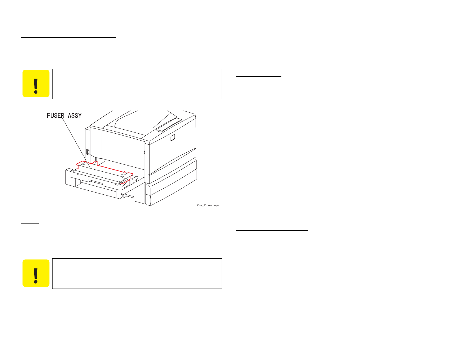
High Temperature Assembly
To prevent you from becoming injured or burned, do the following: Before working
with a high temperature Assembly (e.g., FUSER ASSY), turn off the power, unplug the
power cord and wait until it cools down.
Do not work with wet or oily hands-you may drop a part or injure yourself. Dry
your hands first.
When pulling out a part (including a harness), do not use too much force. Pull out
the part carefully and slowly step by step.
C A U T I O N
The high temperature Assembly is very hot immediately after any
printer operations. Wait at least 40 minutes before you start
working on the printer.
Parts
To prevent you from becoming injured, keep the following in mind:
When handling heavy parts (including the printer itself), use good posture to
protect your back whenever you lift, move or place parts.
Consumables
Understand the following explanation and handle the consumables carefully.
Some parts may cause a particulate explosion or fire if handled improperly. Do not
handle these parts near fire or throw into a fire.
Some materials (e.g., Developer or Fuser Oil) may cause bodily injury. Do not
swallow or inhale these materials or allow them to come in contact with the eyes.
Help to protect those around you and follow the prohibitions against swallowing
or inhaling those materials. Be careful to protect the eyes at all times.
Place a sheet inside or under the printer so that the floor or workbench is protected.
If the Developer or Fuser Oil gets on your clothing, dry it with a cloth and wash
with clean water.
The printer has the following consumable parts:
• DRUM CARTRIDGE
(Photoconductor Unit)
• TONER CARTRIDGE Y • TONER CARTRIDGE M
• TONER CARTRIDGE C • TONER CARTRIDGE BK
• WASTE TONER BOX
Improper Printer Use
Modifying, revising, tampering with the printer, especially to the safety mechanism, is
strictly prohibited in all circumstances.
C A U T I O N
Do not lift, move or place heavy parts in a body posture that is
likely to cause injury to yourself or cause the part to drop.
Be careful not to injure yourself with the sharp edges of the parts.
Page 10

Safety System Outline Diagram
The following diagram shows outline of the safety system of this printer.
For names and other details of signal lines, refer to “7.2 Wiring Diagrams and Signal
Information (p. 465)”.
Page 11

Revision Status
Revision Date of Issue Description
A March 14, 2002 Formal First Release
Note: Exploded Diagrams and ASP List for AcuLaser C7000 are not included in this revision.
B April 10, 2002 Revision up:
[Appendix]
7.8 Optional Units (p.562)
(Description for available options are added.)
C June 27, 2002 Revision up:
[Chapter-3]
3.4.2.1 Rolls and Print Quality Defect Intervals (p. 250)
(Interval pitch for "HEAR ROLL", "PRESSURE ROLL" is corrected.)
3.4.2.12 FIP-1.P11 Interval Print Quality Defect (p.256)
(Newly added.)
Page 12

EPSON AcuLaser C8600/AcuLaser C7000 Revision C
Contents
Chapter 1 Product Description
1.1 Features ................................................................................................................. 7
1.1.1 Engine Features ........................................................................................... 7
1.1.2 Controller Features ...................................................................................... 7
1.1.3 Software Features ........................................................................................ 8
1.2 Basic Specifications .............................................................................................. 9
1.2.1 Printer Basic Specifications ......................................................................... 9
1.2.2 Paper Specifications ................................................................................... 15
1.2.3 Reliability, Durability and Maintainability ................................................ 20
1.2.4 Operating Conditions (Including Consumables) ....................................... 21
1.2.5 Storage and Transport of the Printer Body and Optional Products
(Consumables Packaged) .................................................................................... 22
1.2.6 Electrical Features ..................................................................................... 23
1.2.7 Process Specifications ............................................................................... 24
1.2.8 Compliance with Standards and Regulations ............................................ 24
1.2.9 Consumable Components .......................................................................... 25
1.3 External View and Parts Names ......................................................................... 28
1.3.1 External View and Parts Names ................................................................ 28
1.3.2 Dimensional Drawing (in mm) .................................................................. 31
1.4 Controller Specifications .................................................................................... 33
1.4.1 Basic Controller Specifications ................................................................. 33
1.4.2 Controller Configuration ........................................................................... 34
1.4.3 Calibration Function (only with AcuLaser C8600) ................................... 34
1.5 External Interface Specifications ........................................................................ 35
1.5.1 Parallel Interface Specifications ................................................................ 36
1.5.2 USB Interface Specifications ..................................................................... 37
1.5.3 Ethernet Interface ....................................................................................... 37
1.5.4 Type-B Interface Specifications ................................................................ 38
1.6 Control Panel (AcuLaser C8600) ....................................................................... 40
1.6.1 External View and Names ......................................................................... 40
1.6.2 Description of Indicators ........................................................................... 40
1.6.3 Description of Buttons ............................................................................... 41
1.6.4 Operation and Indications on the Control Panel ........................................ 43
1.6.5 Panel Setting Item List .............................................................................. 45
1.6.6 User Setting Items Other Than Setup Menu .............................................. 52
1.6.7 Details of Setting Menus and Setting Items .............................................. 52
1.6.8 Special Operations ..................................................................................... 57
1.7 Control Panel (AcuLaser C7000) ....................................................................... 58
1.7.1 External View and Names ......................................................................... 58
1.7.2 Indications of LEDs ................................................................................... 58
1.7.3 Printer Setting Items .................................................................................. 59
1.8 Engine Restrictions ........................................................................................... 65
1.9 Status Sheet, etc. ................................................................................................. 70
1.9.1 Status Sheet for AcuLaser C8600 .............................................................. 70
1.9.2 Status Sheet for AcuLaser C7000 .............................................................. 72
1.9.3 Reserve Job List (Only with AcuLaser C8600) ......................................... 73
1.9.4 Form Overlay List (Only with AcuLaser C8600) ..................................... 73
1.9.5 Network Status Sheet (Only with AcuLaser C8600) ................................. 74
1.9.6 Engine Status Sheet ................................................................................... 75
1.10 Restrictions (Only for AcuLaser C7000) ......................................................... 79
1.10.1 Network Environment Applicable to AcuLaser C7000 .......................... 79
1.10.2 Restrictions on Network Connections ..................................................... 79
1.10.3 Others ....................................................................................................... 79
1.11 Operating Conditions of Host Computers (Only for AcuLaser C7000) .......... 80
1.12 RAM Expansion ............................................................................................... 81
1.13 Precautions in Handling ................................................................................... 82
1.13.1 Precaution in Turning Off the Power ...................................................... 82
1.13.2 Caution About Hot Parts .......................................................................... 82
1.14 Paper Handling Algorithm (AcuLaser C8600) ................................................ 83
1.15 Differences in Specifications ............................................................................ 86
1.15.1 Differences between AcuLaser C7000 and AcuLaser C8600 ................. 86
1.15.2 Differences in Specifications between Models ....................................... 87
6
Page 13

EPSON AcuLaser C8600/AcuLaser C7000 Revision C
Chapter 2 Operating Principles
2.1 Print Process ....................................................................................................... 91
2.1.1 Print Process Overview .............................................................................. 91
2.1.2 Total Print Process Schematic Diagram .................................................... 91
2.1.3 Print Process Technical Explanation ......................................................... 92
2.1.4 Print Data Flow ........................................................................................ 101
2.1.5 Operation Mode ....................................................................................... 102
2.2 Mechanism Operating Principles ..................................................................... 103
2.2.1 Drive Transmission Route ....................................................................... 103
2.2.2 Gear Layout ............................................................................................. 106
2.2.3 Paper Feed ............................................................................................... 108
2.2.4 Function of Main Working Parts ............................................................. 110
2.3 Control .............................................................................................................. 130
2.3.1 Paper Size Control ................................................................................... 130
2.3.2 Paper Supply Unit Selection Control ....................................................... 131
2.3.3 OHP Front/Back Detection Control ......................................................... 131
2.3.4 ROS Control ............................................................................................ 132
2.3.5 Process Control ........................................................................................ 134
2.3.6 XERO. Control ........................................................................................ 142
2.3.7 DEVE. Control ........................................................................................ 145
2.3.8 IBT Control .............................................................................................. 149
2.3.9 Transfer Layout Control .......................................................................... 153
2.3.10 FUSER Control ...................................................................................... 155
2.4 Operating Principles of Electric Circuitry ........................................................ 157
2.4.1 Features (AcuLaser C8600) ..................................................................... 157
2.4.2 Features (AcuLaser C7000) ..................................................................... 159
3.3 Level 2 FIP ....................................................................................................... 226
3.3.1 Level 2 FIP List ....................................................................................... 226
3.4 Picture Image Trouble ...................................................................................... 249
3.4.1 Picture Image Troubleshooting Entry Chart ............................................ 249
3.4.2 Picture Quality FIP .................................................................................. 249
Chapter 4 Disassembly and Assembly
4.1 Overview ............................................................................................... 258
4.1.1 Precautions ............................................................................................... 258
4.1.2 Tools ........................................................................................................ 260
4.1.3 Items to Check after Assembly ................................................................ 260
4.2 Disassembly and Reassembly Procedure ......................................................... 261
4.2.1 Cover ....................................................................................................... 262
4.2.2 Paper Tray ................................................................................................ 270
4.2.3 Paper Feeder ............................................................................................ 274
4.2.4 MSI/Paper Transportation ....................................................................... 282
4.2.5 (Missing number) .................................................................................... 297
4.2.6 Xerographics ............................................................................................ 298
4.2.7 Development ............................................................................................ 305
4.2.8 IBT ........................................................................................................... 312
4.2.9 Fusing ...................................................................................................... 321
4.2.10 Paper Exit .............................................................................................. 339
4.2.11 Drive ...................................................................................................... 345
4.2.12 Frame ..................................................................................................... 351
4.2.13 Electrical ................................................................................................ 352
4.2.14 Controller ............................................................................................... 358
Chapter 3 Troubleshooting
3.1 Overview .......................................................................................................... 162
3.1.1 Troubleshooting Procedure ...................................................................... 162
3.1.2 Preliminary Checks .................................................................................. 162
3.1.3 Precautions in Performing Work ............................................................. 163
3.1.4 Self-Diagnostic Function by Printer Message (AcuLaser C8600) .......... 164
3.1.5 Self-Diagnostic Function by Printer Message (AcuLaser C7000) .......... 172
3.1.6 Details of the Service Call Error Messages ............................................. 180
3.2 Level 1 FIP (Fault Isolation Procedure) ........................................................... 184
3.2.1 Precautions in Using FIP (Fault Isolation Procedure) ............................. 184
Chapter 5 Adjustment
5.1 Overview .......................................................................................................... 361
5.1.1 Specified Tools ........................................................................................ 361
5.2 USB ID Input .................................................................................................... 362
5.2.1 Installation Procedure for Program .......................................................... 362
5.2.2 Procedure for Program Operation ............................................................ 362
5.2.3 USB ID Confirmation .............................................................................. 363
5.3 Service Utility (for AcuLaser C7000) .............................................................. 364
5.3.1 Overview ................................................................................................. 364
5.3.2 How to Use the Service Utility ................................................................ 365
7
Page 14

EPSON AcuLaser C8600/AcuLaser C7000 Revision C
5.3.3 Operation ................................................................................................. 367
5.4 Diagnostics ....................................................................................................... 369
5.4.1 Diagnostics by Operating the Printer Body Only ................................... 369
5.4.2 Diagnostics Commander .......................................................................... 371
Chapter 6 Maintenance
6.1 Overview .......................................................................................................... 448
6.1.1 Regularly Replaced Parts Replacement ................................................... 449
6.1.2 Main After-Sales Parts Replacement ....................................................... 449
6.1.3 Consumable Replacement ....................................................................... 449
6.2 About On-Site Servicing .................................................................................. 450
6.2.1 On-site Service Flow ............................................................................... 450
6.2.2 Description of the On-site Service ........................................................... 451
6.3 Maintenance Menu (AcuLaser C8600) ............................................................ 453
6.3.1 Entry to the Maintenance Menu (AcuLaser C8600) ................................ 453
6.3.2 Maintenance Menu Items (AcuLaser C8600) .......................................... 454
Chapter 7 APPENDIX
7.1 Connectors ........................................................................................................ 457
7.1.1 P/J Location Drawings ............................................................................. 457
7.2 Wiring Diagrams and Signal Information ........................................................ 465
7.2.1 Overall Wiring Connection Diagram ....................................................... 465
7.2.2 Wiring and Signal Descriptions between Components ........................... 467
7.3 Component Layout ........................................................................................... 489
7.4 Circuit Diagrams .............................................................................................. 491
7.5 Exploded Diagrams .......................................................................................... 503
7.6 Index for Parts .................................................................................................. 550
7.7 ASP List (Parts List) ......................................................................................... 554
7.7.1 ASP List for AcuLaser C8600 ................................................................. 555
7.7.2 ASP List for AcuLaser C7000 ................................................................. 558
7.8 Optional Units .................................................................................................. 562
7.8.1 Duplex Unit ............................................................................................. 563
7.8.2 500-Sheet Paper Cassette Unit ................................................................. 609
7.8.3 Large Capacity Paper Unit ....................................................................... 659
7.8.4 ASP Information ...................................................................................... 716
8
Page 15

PRODUCT DESCRIPTION
CHAPTER
1
Page 16

EPSON AcuLaser C8600/AcuLaser C7000 Revision C
1.1 Features
AcuLaser C8600/AcuLaser C7000 is a non-impact color page printer driven by a laser
and electrophotographic technologies. The resolution is 600/300 dpi and the printing
speed is 8 ppm (A4 color)/35 ppm (A4 monochrome). The printer is equipped with
AcuLaser Color Halftoning as its full color technology.
1.1.1 Engine Features
AcuLaser C8600 has the following features.
High-speed engine that supports A5 to A3W. Printing speed is 8 ppm for color/35
ppm for monochrome (when printing A4 paper).
Full-color printing engine that supports duplex printing and True 600 dpi of high
resolution.
Higher quality printing is possible with high quality plain paper.
Capable of printing on thick paper, extra thick paper, coated paper, and
transparency (dedicated OHP sheets).
Easy maintenance for a color laser printer.
As the standard paper feeders, the printer has two bins, namely, the MP Tray (up to
150 sheets, A3W supported) and the standard universal cassette (up to 250 sheets,
A3 supported).
Adding an optional Large Capacity Paper Unit (two 500-sheet cassettes, A3
supported) allows paper feeding a maximum of 1400 sheets from 4 bins.
Adding an optional 500-Sheet Paper Cassette Unit (one 500-sheet cassette, A3
supported) allows paper feeding a maximum of 900 sheets from 3 bins.
Substituting the standard universal cassette with an A3W paper cassette allows
feeding A3W paper from the Lower Cassette 1.
As paper ejection, a maximum of 250 sheets can be ejected into the Face-down
tray and 150 sheets into the Face-up tray.
1.1.2 Controller Features
1.1.2.1 Controller Features for AcuLaser C8600
Newly developed high-speed controller
New RISC CPU ..............................PowerPC750CX (400MHz)
64-bit high-speed memory .............SDRAM DIMM (PC100 or PC133)
64 MB of standard RAM. By installing additional RAM (2-slot), the memory
can be expanded up to 1 GB (removing the standard RAM and installing 512
MB RAM on both slots). Using the standard RAM as it is expands up to 576
MB.
Color technologies
Enhanced ASIC (VIPS, CDMC) installed
Data compression has been incorporated into the hardware to achieve high-
speed processing.
Equipped with AcuLaser Color Halftoning and CRIT (color RIT)
On-board option of color photocopier (AcuLaser Color Copy Station 8600)
supported
Three types of standard interfaces available
IEEE1284 compatible parallel interface (ECP supported)
USB (Rev. 1.1) interface
Ethernet interface (100Base-TX/10Base-T)
By expanding memory with RAM DIMMs, the following functions can be
enhanced and speeded up.
Drawing area for AcuLaser Color Halftoning
Printing speed
Resolution
Receive buffer capacity
Collate (printing of multiple copies) (with memory expanded to 128 MB or
more)
New control panel (control panel 2001)
HDD can be installed.
Product Description Features 7
Page 17

EPSON AcuLaser C8600/AcuLaser C7000 Revision C
1.1.2.2 Controller Features for AcuLaser C7000
Host-based controller
CPU: TMPR4955AF-200 MHz
Standard RAM: 32 MB, adding RAM DIMM expands to a maximum of 256
MB (Requires to replace the standard 32MB RAM DIMM
with 128MB.)
Color technologies
Enhanced ASIC (VIPS) installed
Equipped with AcuLaser Color Halftoning and CRIT (color RIT)
Two types of standard interfaces installed
IEEE1284 compatible parallel interface supporting ECP
USB I/F
Expanding RAM DIMM allows providing enhanced and high-speed performances
on the following functions
Drawing area for AcuLaser Color Halftoning
Printing speed
Resolution
1.1.3 Software Features
1.1.3.1 Software Features for AcuLaser C8600
Installed emulation
Standard ............ ESC/Page-Color mode
Standard ............LJ4, GL2, ESCP2, FX, I239X, and ESC/Page
(monochrome) modes (these have complete compatibility
with AcuLaser C8500)
Optional .............PostScript 3 mode (PostScript 3 module)
Optional ............. Color Copy Unit (AcuLaser Color Copy Station 8600)
HP LaserJet4000, 80 Scalable font and compatible fonts and NLSP font ROM are
installed, and Euro Symbol is supported
Electronic sort, extended interface receive buffer size (for Ethernet interface only,
excluding when emulation is fixed for PS3), font registration when PostScript 3
mode is selected (with an HDD installed)
Calibration function
Form Overlay function (for ESC/Page Color mode of Windows driver only, with
an HDD installed)
Reserve job function (Re-Print Job, Verify Job, Stored Job, Confidential Job, with
an HDD installed)
Color design has been changed (sRGB, gray scale guarantee for graphics, can be
rewritten into the color design of AcuLaser C8500 (for Flash Program DIMM
only))
NOTE: This is not described in manuals.
Specifications of manual feed have been changed (same as EPL-5900).
1.1.3.2 Software Features for AcuLaser C7000
ESC/PageS implemented
Supports color
Supports duplex printing
Supports 2up
Network compatibility
Background job commands establish network connections
Printer status and printer environment monitors by EJL, PJL, and Printer MIB
Remote panel function through HTTP browser by the EpsonNet WebAssist
ROM update function when a flash DIMM is installed (RCC is supported)
Upgrade function of the engine controller ROM (flash)
Engine transfer voltage adjustment function by DIAG mode and control panel
Product Description Features 8
Page 18

EPSON AcuLaser C8600/AcuLaser C7000 Revision C
1.2 Basic Specifications
1.2.1 Printer Basic Specifications
Printing Method
Semi-conductor laser beam scanning and dry two-component toner
electrophotography
Resolution
600 dpi
Print Mode
B/W mode ................. Standard monochrome print mode in which printing is
performed at the fastest speed.
Color mode................ Color mode which uses the color toner of Y, M, C, and
K.
Speed Mode
Standard mode........... Transports paper at the highest speed supported by the
printer.
Middle speed mode ... This mode ensures satisfactory fusing of image on
thick paper exceeding 105 g/m
and monochrome image on transparencies.
This mode also reduces printing speed to enhance the
degree of gloss on the surface of the dedicated coated
paper.
Low speed mode ....... This mode reduces printing speed to ensure satisfactory
fusing of image on thick paper exceeding 220g/m
color image on transparencies.
2
(28 lb) or envelopes,
2
, and
Printing Speed *
3
Both face-up and face-down satisfy the conditions below.
All of the standard tray, the standard universal cassette and the expanded cassette
satisfy the following conditions:
Table 1-1. Printing Speed (Unit: ppm)
Print
Mode
B/W
Color
Note *1: LEF (Long Edge Feed): the long edge of the paper is fed to the printer.
*2: In 2UP mode, the printer creates two print images on the IBT belt and the images are
*3: Not applicable to any operation for which the printing speed is restricted as specified
*4: The printing speed (ppm) for Duplex printing represents the number of pages printed
Speed Mode
Simplex
Standard
Middle
speed
Low speed
Standard
Middle
speed
Low speed
SEF (Short Edge Feed): the short edge of the paper is fed to the printer.
transferred in sequence onto two sheets of paper. This mode is available for LT/A4
(LEF) or smaller.
in 1.8 "Engine Restrictions".
per minute.
The values in parentheses represent the printing speeds when paper is fed from the
optional 500-Sheet Paper Cassette Unit (500 sheets x 1) or the optional Large
Capacity Paper Unit (500 sheets x 2). (The two values given in parentheses indicate
the printing speeds with the optional upper cassette and lower cassette, respectively.)
printing
Duplex
printing *
Simplex
printing
Simplex
printing
Simplex
printing
Duplex
printing *
Simplex
printing
Simplex
printing
A4 LEF
(33.7/27.5)
27.4 (25.5) 27.1 (25.4) 15.7 (15.6) 15.5 (15.4)
4
4
*1
LT LEF
2
2UP *
35.0
(32.9/27.5)
5.3 5.3 2.6 2.6
4.0 4.0 2.0 2.0
8.0 8.0 4.0 4.0
8.0 8.0 4.0 4.0
3.5 3.5 1.8 1.8
2.9 2.9 1.4 1.4
2UP *
34.4
*1
A3 SEF *1B(LD) LEF
2
18.8 (18.3) 18.3 (17.9)
*1
Product Description Basic Specifications 9
Page 19

EPSON AcuLaser C8600/AcuLaser C7000 Revision C
Reference values
B/W, standard mode. With paper sizes other than indicated above when paper
is fed from the standard universal cassette, the printing speeds for your
information are as shown below.
Table 1-2. Reference Values (Unit: ppm)
Paper Size EXE LEF B5 LEF LD14” B4 SEF
Simplex printing 39.2 39.8 21.9 21.5
Duplex printing 40.4 40.7 17.1 16.9
<How to measure continuous printing speed>
The number of sheets printed per minute is measured as follows: Let t seconds be the
time from the ejection of the tail end of the 1st sheet to the ejection of the 11th sheet.
Then the number of sheets printed per minute is calculated as 60/t times the measured
number of pages.
First Printing Time *
Face-up...................... B/W : 8.3 seconds or less
Color : 19.6 seconds or less
Face-down................. B/W : 10.4 seconds or less
Color : 21.7 seconds or less
NOTE 1:
First print is defined as the duration taken after receiving the start command
until completion of outputting the first print. It is applicable when a feeder in
the printer body is selected in the standard mode. (Not applied during the
process control operation.)
2:
The time as indicated above is common to all the feeders including all the
optional feeders.
3:
The values as indicated above are applicable when the paper is A4 LEF.
Warm-up time
Within 330 seconds (at 22°C, 55% Rh, rated voltage: 100V, 115V, 220V)
Paper feed
Table 1-3. Paper Feed
Paper Source Capacity Applicable Paper Size
Standard Standard MSI
(MP tray)
Standard
universal cassette
Optional
Cassette
Unit *
A3W Cassette
2
500-Sheet Paper
Cassette Unit
Large Capacity
Paper Unit
*1
,*4
150 sheets
(16 mm)
75 sheets
20 sheets
250 sheets
(26 mm)
250 sheets
(26 mm)
500 sheets
(53 mm)
500 sheets
(53 mm)
Regular size sheets and custom size
sheets whose dimensions are within the
limits specified below:
• Min.: Width 90 mm (3.5")x
Length 139.7 mm (5.5")
• Max.: Width 330.2 mm (13")x
Length 457.2 mm (18")
A3, A3W, A4, A5, B4, B5, I-B5, LT,
HLT, LG, EXE, GLG, GLT, B(LD),
F4
90x139.7 mm∼330.2x457.2 mm
Postcard, Double postcard, Quadruple
postcard, Transparencies, Labels,
Thick paper
Custom-size envelopes *
Monarch, C10, DL, C6, C5
Yokei #0
B5, LT, A4, B4, A3, LG, B(LD), EXE 64∼105g/m
A3W 64∼105g/m
B5, LT, A4, B4, A3, LG, B(LD), EXE 64∼105g/m
B5, LT, A4, B4, A3, LG, B(LD), EXE 64∼105g/m
*
6
, Yokei #4
3
*
6
, Yokei #6
64∼105g/m
(Recommended
paper, Plain
paper)
105∼250g/m
(Thick paper,
Special paper)
*
6
(Recommended
paper, Plain
paper)
(Recommended
paper, Plain
paper)
(Recommended
paper, Plain
paper)
(Recommended
paper, Plain
paper)
Applicable
Paper
Thickness
2
2
-
2
2
2
2
Note *1: For the paper whose width is more than 304.8 mm (12 inch), the side guide in the
MSI tray must be adjusted.
*2: Each cassette is equipped with the side guide and end guide (also used to detect
paper size). They can be adjusted by users.
Product Description Basic Specifications 10
Page 20

EPSON AcuLaser C8600/AcuLaser C7000 Revision C
*3: Note the following points when setting envelopes:
Open the flaps and set the envelopes with the flaps positioned at the tail in the paper
feed direction.
Set the envelopes so that the longer edge is fed to the printer, if the length (excluding
the flap) is shorter than the width. (Except for C5)
The minimum length with the flap open must be 143 mm.
The minimum width must be 90 mm.
*4: The MSI tray has the function to detect Paper Empty condition.
*5: Each cassette is equipped with the Paper Out sensor and paper near empty sensor.
Paper Near Empty condition is defined as follows: 40 sheets
paper (64 g/m2)
*6: JIS envelope
± 30 sheets of FX P
Combinations with Optional Cassettes and Resultant Capacity
MSI
Combination
1
2 250 sheets - - 1000 sheets 1400 sheets
3 - 250 sheets 500 sheets - 900 sheets
4 - 250 sheets - 1000 sheets 1400 sheets
NOTE a: The number of sheets is applicable when recommended paper or plain paper is used.
b: Use the A3W cassette by inserting it into the standard universal cassette slot.
c: Either 500-Sheet Paper Cassette Unit or Large Capacity Paper Unit can be installed
(MP
Tray)
150
sheets
only at the bottom.
Standard
Universal
Cassette
250 sheets - 500 sheets - 900 sheets
A3W
Cassette
500-Sheet
Paper
Cassette
Unit
Large
Capacity
Paper Unit
Total
Capacity
Duplex Printing
Minimum size .......... 182 mm/7.16” (W) x 210 mm/8.26” (L)
Maximum size .......... 304.8mm/12” (W) x 457.2mm/18” (L)
Paper wight .............. 64 g/m
2
∼105 g/m2 (17 lb∼28 lb)
Paper Size / Paper Orientation / 2-UP Mode Availability
Table 1-4. Paper Size / Paper Orientation /
2-UP Mode Availability
Paper Orientation
Dimensions
Paper Size
A3W 328x453 SEF - - SEF
A3 297x420 SEF SEF SEF A4 210x297 LEF LEF LEF - { {
A5 148x210 LEF - - - {
B4 257x364 SEF SEF SEF B5 182x257 LEF LEF LEF - { {
I-B5 176x250 LEF - - - {
LT
HLT
Plain paper
LG
EXE
GLG
GLT
B(LD)
F4 210x330 SEF - - -
mm
(inch)
215.9x279.4
(8.5”x11”)
139.7x215.9
(5.5”x8.5”)
215.9x355.6
(8.5”x14”)
184.15x266.7
(7.25”x10.5”)
215.9x330.2
(8.5”x13”)
203.2x266.7
(8”x10.5”)
279.4x431.8
(11”x17”)
MSI
Universal
(MP
Tray)
LEF LEF LEF - { {
LEF - - - {
SEF SEF SEF -
LEF LEF LEF - { {
SEF - - -
LEF - - - { {
SEF SEF SEF -
Casette
500-
Sheet/
LCP
Unit
A3W
Cassette
2UP
mode
*1
X X
X
X
X
X
X
X
Duplex
print
{
X
{
X
X
{
{
{
{
Product Description Basic Specifications 11
Page 21

EPSON AcuLaser C8600/AcuLaser C7000 Revision C
Table 1-4. Paper Size / Paper Orientation /
2-UP Mode Availability (continued)
Paper Orientation
Paper Size
Transparencies
Dimensions
mm
(inch)
210x297
(8.5”x11”)
MSI
Universal
(MP
Tray)
Casette
LEF - - - {
Postcard 100x148 SEF - - - {
Double postcard 148x200 LEF - - - {
Special applications
Quadruple
postcard
MON
C10
DL 110x220 LEF*
200x296 LEF - - - {
98.43x190.54
(37/8”x71/2”)
104.78x241.3
(41/8”x91/2”)
LEF*
LEF*
2
- - - {
2
- - - {
2
- - - {
C5 162x229 SEF - - C6 114x162 LEF*
Yokei #0
Yokei #4
Yokei #6
*3
*3
*3
120x235 LEF*
105x235 LEF*
98x190 LEF*
2
- - - {
2
- - - {
2
- - - {
2
- - - {
500-
Sheet/
LCP
Unit
A3W
Cassette
2UP
mode
*1
X X
Duplex
print
X
X
X
X
X
X
X
X
X
X
X
Paper Feed Reference
Single side aligning (front side) for all sizes (both standard tray (MSI) and each
cassette)
Consumables
Toner Cartridge (Black, Cyan, Magenta, Yellow)
Drum Cartridge (including one Waste Toner Box)
Waste Toner Box
Regularly Replaced Parts
Main Fuser Assembly
Exhaust Filter
Paper Output
Paper output capacity with the recommended paper (EPSON high-quality paper) is
as follows:
Face-down (FD) ......................250 sheets (B5/EXE or larger, up to 105 g/m
(28 lb))
Face-up (FU) ...........................150 sheets (A4 or smaller)
50 sheets (larger than A4)
NOTE: The FD and FU output capacities are applicable to both simplex and
duplex prints. (when recommended paper is used)
See Table 1-5 on page 13 for face-down (FD) output availability.
2
NOTE a: LEF (Long Edge Feed): the long edge of the paper is fed to the printer.
b: SEF (Short Edge Feed): the short edge of the paper is fed to the printer.
c: The envelopes supported vary with intended markets.
Note *1: 2UP is available only for paper size of LT (LEF) or smaller. For custom size paper,
paper length along the transport direction must be 210 mm (8.5 inches) or shorter.
As for envelopes, the length with its flap opened along the transport direction must
be 210 mm (8.5 inches) or shorter.
*2: When setting envelopes, open the flaps and set the envelopes with the flaps
positioned at the tail in the paper feed direction.
*3: JIS envelope
Product Description Basic Specifications 12
Page 22

EPSON AcuLaser C8600/AcuLaser C7000 Revision C
Plain paper
Special
applications
Table 1-5. Face-Down Output Availability
Paper Size Dimensions in mm (inch) FD Availability
A3W 328x453 {
A3 297x420 {
A4 210x297 {
A5 148x210
B4 257x364 {
B5 182x257 {
I-B5 176x250
LT 215.9x279.4 (8.5”x11”) {
HLT 139.7x215.9 (5.5”x8.5”)
LG 215.9x355.6 (8.5”x14”) {
EXE 184.15x266.7 (7.25”x10.5”) {
GLG 215.9x330.2 (8.5”x13”) {
GLT 203.2x266.7 (8”x10.5”) {
B(LD) 279.4x431.8 (11”x17”) {
F4 210x330 {
Transparencies 210x297 (8.5”x11”) FU
Postcard 100x148 FU
Double postcard 148x200 FU
Quadruple postcard 200x296 FU
MON 98.43x190.54 (37/8”x71/2”) FU
C10 104.78241.3 (41/8”x91/2”) FU
DL 110x220 FU
C5 162x229 FU
C6 114x162 FU
Yokei #0
Yokei #4
Yokei #6
*1
*1
*1
120x235 FU
105x235 FU
98x190 FU
X
X
X
*
*
*
*
*
*
*
*
*
*
*
*
NOTE a: FD ejection is not available with sheets larger than 181.9 mm in the paper feeding
direction and 209.9 mm in width.
b: “FU*” in the FD availability columns means face-up ejection for transparencies,
thick paper, and envelope.
c: The FD and FU output capacities are applicable to both simplex and duplex prints
(when recommended paper is used).
Note *1: JIS envelope
Dimensions and Weight
Table 1-6. Dimensions and Weight of Each of
AcuLaser C8600 Printer Body and Optional Units
Dimensions
Printer
body
Width
(mm)
AcuLaser C8600 650
AcuLaser C7000 650
Duplex Unit *
2
Depth
(mm)
*1
647 554 70.0
*1
647 554 69.5
Height
(mm)
- - - 8.2
500-Sheet Paper Cassette Unit (with Feet) 575 602 164 13.3
Option
500-Sheet Paper Cassette Unit (with
Castors)
575 602 206 14.0
Large Capacity Paper Unit 578 602 264 21.2
A3W Cassette 560 547 87.4 ± 1.2 2.7
Note *1: With the MSI (MP Tray) and the paper eject (FU) tray folded
*2: Since the Duplex Unit consists of three separate components, the dimensions of the
Duplex Unit as a single unit are not given.
NOTE a: For printer dimensions with its optional units installed, see Section 1.3.2
"Dimensional Drawing (in mm)".
b: The tolerance of the dimensions is ± 1 mm.
c: The total weight after installing optional units is not the total sum of the weights of
the printer body and the installed optional units, since their installation involves
some part removal.
Weight
(kg
±1%kg)
Power Supply
100/120V version:100/120V±10% (90V∼132V) 50/60Hz±3Hz
220/240V version:220/240V±10% (198V∼264V) 50/60Hz± 3Hz
Product Description Basic Specifications 13
Page 23

EPSON AcuLaser C8600/AcuLaser C7000 Revision C
Power Consumption
Power consumption with the rated voltage (100, 115 or 240 VAC) input is as
follows:
Table 1-7. Power Consumption
Power Consumption Remarks
Average 550 Wh or less
Operating (color)
Operating (B/W)
Standby mode
Low power mode *
Note *1: Including the optional cassette unit and duplex printing unit.
*2: Full pause status. Conforms to the Energy Star program.
*1
Maximum
Average 750 Wh or less
*1
Maximum
Average 240 Wh or less
Maximum
2
Average
1100 W or less 100V/120V version (Fuser is on)
1200 W or less 220V/240V version (Fuser is on)
1100 W or less 100V/120V version (Fuser is on)
1200 W or less 220V/240V version (Fuser is on)
1000 W or less (Fuser is on)
100 W or less (Fuser is off)
20 Wh or less Only with Japanese models
15 Wh or less
AcuLaser C8600/AcuLaser C7000)
(Not applicable to
Current Consumption
100 V ..............................................11 A or less (at rated voltage)
115 V ..............................................10 A or less (at rated voltage)
240 V ..............................................5 A or less (at rated voltage)
Product Life
Printer body (including the standard tray):
Approximately 180,000
years, whichever comes first.
*1
printed pages (450,000 images) on A4 LEF or five
Option
• 500-Sheet Paper Cassette Unit .............. 180,000 sheets
• Large Capacity Paper Unit .................... 180,000 sheets
• A3W Cassette ........................................ 180,000 sheets
• Duplex Unit ...........................................180,000 sheets*
Note *1: Note one full color print is formed with four images. So the printer can prints 180,
000 sheets (= 450,000 images) if its job ratio of monochrome printing to color
printing is 1:1. (450,000 images = 90,000 x 4 + 90,000).
If the printer is used only for monochrome print, it can prints 450,000 sheets
*2: In duplex printing, each side of paper is counted as one sheet.
2
Noise
Table 1-8. Noise
Status Printer Body Only Printer Body + Optional Units
Operating 54.8dB(A) or less 59.4dB(A) or less
Standby mode 38.3dB(A) or less 38.3dB(A) or less
Low power mode 35.0 dB(A) or less 35.0 dB(A) or less
Note *1: Duplex Unit + Large Capacity Paper Unit
*1
Ozone Concentration
The saturated concentration of ozone emission does not exceed 0.02 mg/m
Measurement is based on the BAM standard. The volume subjected to
measurement is 29.3 m
3
.
3
.
Dust Emission
Dust concentration is not more than 0.075 mg/m
BAM standard.
3
. Measurement is based on the
Toxicity
Photoconductor unit (OPC), toner, carrier, and plastic materials are all non-toxic.
Product Description Basic Specifications 14
Page 24

EPSON AcuLaser C8600/AcuLaser C7000 Revision C
1.2.2 Paper Specifications
1.2.2.1 Paper Type
Recommended Paper
4200 paper (B/W), X-Pressions paper (color), EPSON high-quality plain paper
(for color single-side only), EPSON coated paper
Plain Paper
Generally applied copier paper, Recycled paper,
2
64 g/m
Special Applications
Exclusive OHP film (Type: LPCOHPS1)
Postcard
Labels
Color paper
Thick paper (105 g/m
Envelope
NOTE 1:
~ 105 g/m2 (17 lb ~ 28 lb)
2
~ 250 g/m2)
lb: Ream Weight =lb/500 sheets/17”
2
1g/m
=0.2659763 lb
2:
Before purchasing a large amount of paper, try it out and check that it is
×
22"
properly fed.
3:
The following types of paper should not be used with this printer. They could
cause printing defects, paper jams or printer malfunctions.
• Carbon paper, non-carbon paper, thermal paper, impact paper, acid-based
paper
• Paper that was previously used in a thermal or ink jet printer
• Paper that is too thin or too thick
• Paper that is wet or damp
• Paper with special coatings or colored paper with processed surfaces
• Paper that is too smooth or slippery on the surface
• Paper with significantly different roughness on each surface
• Paper with punch holes or perforations
• Irregularly shaped paper or paper with non-perpendicular corners
• Labels that peel off easily
• Paper with glue, staples or paper clips attached to it
• Ink jet paper for special applications (super-fine, glossy, glossy film, etc.)
• OHP sheets manufactured for other color laser printers, monochrome
printers, and photocopiers
• Sheets already printed on other color/monochrome laser printers or
photocopiers
• Sheets of paper stuck together
1.2.2.2 Paper Feedings
Table 1-9. Paper Feedings
Special Applications
Postcard
Double
postcard
Quadruple
postcard
2
Labels
∆ ∆ ∆ ∆
X X X X X
X X X X X
X X X X X
X X X X X
Paper Source
Standard tray
(MSI)
Standard
Universal
Cassette
A3W Cassette
500-sheet
*1
Cassette
Duplex Unit
Recommended
*1
*1
Paper
{
{
{
{
{
Plain
Paper
∆
∆
∆
∆
∆
OHP
{ *
Note *1: Option
*2: Exclusive OHP sheet only
{: Paper feed reliability and image quality are ensured.
∆: Paper feed and printing are possible for only generally applied types of paper.
X
: Sheets cannot be fed.
Thick
paper
(105∼250
2
g/m
)
Envelope
(MON,
C10, DL,
C6, C5,
Yokei #0
*3
#4
, #6*3)
*3
,
Product Description Basic Specifications 15
Page 25

EPSON AcuLaser C8600/AcuLaser C7000 Revision C
1.2.2.3 Printing Area
PRODUCT SPECIFICATIONS
There are two types of printing areas, namely, the guaranteed print area and the
printable area.
Guaranteed Print Area:
Print quality is guaranteed all over the guaranteed print area.
Printable Area:
Printing is always possible all over the printable area. (Print quality is not
guaranteed out of the guaranteed print area, even within the printable area.)
Printing is not always possible out of the available printing area. (Printing out of
the printable area sometimes may be achieved successfully, but can not always be
achieved.)
The guaranteed print area and printable area are all the area of the sheet except vertical
and horizontal margins of 5 mm. (See illustration below)
However, with the A3W sheet or custom-size sheets with a large size, the guaranteed
print area is different from the printable area.
Guaranteed Print
Area or
Printable Area
Guaranteed Print Area List
Table 1-10. Guaranteed Print Area List (Unit: dots) (600dpi)
Paper Size a
*1
A3W
A3 120 6776 120 120 9680 120
A4 120 4720 120 120 6776 120
A5 120 3256 120 120 4720 120
B4 120 5832 120 120 8360 120
B5 120 4060 120 120 5832 120
LT 120 4860 120 120 6360 120
HLT 120 3060 120 120 4860 120
LG 120 4860 120 120 8160 120
EXE 120 4110 120 120 6060 120
Regular
size paper
Custom
size paper
Note *1: With the A3W sheet or custom-size sheets with a large size, the guaranteed print area
GLG 120 4860 120 120 7560 120
GLT 120 4560 120 120 6060 120
B(LD) 120 6360 120 120 9960 120
F4 120 4720 120 120 7556 120
Postcard 120 2122 120 120 3256 120
Double postcard 120 4484 120 120 3256 120
Quadruple postcard 120 4484 120 120 6752 120
Envelope
(Yokei #0)
Envelope
(Yokei #4)
Envelope
(Yokei #6)
Minimum size 120 1886 120 120 3060 120
Maximum size
is different from the printable area.
*2: JIS envelope
*2
*2
*2
*1
1
390 7016 342 120 10174 406
120 2594 120 120 5310 120
120 2240 120 120 5310 120
120 2074 120 120 4248 120
390 7016 342 120 10174 406
b a
2
c
1
d c
2
print_area01.eps
Figure 1-1. Guaranteed Print Area
Product Description Basic Specifications 16
Page 26

EPSON AcuLaser C8600/AcuLaser C7000 Revision C
Printable Area List
Table 1-11. Printable Area List (Unit: dots) (600dpi)
Paper Size a
*1
A3W
1
120 7508 120 120 10460 120
A3 120 6776 120 120 9680 120
A4 120 4720 120 120 6776 120
A5 120 3256 120 120 4720 120
B4 120 5832 120 120 8360 120
B5 120 4060 120 120 5832 120
LT 120 4860 120 120 6360 120
HLT 120 3060 120 120 4860 120
LG 120 4860 120 120 8160 120
EXE 120 4110 120 120 6060 120
Regular
size paper
GLG 120 4860 120 120 7560 120
GLT 120 4560 120 120 6060 120
B(LD) 120 6360 120 120 9960 120
F4 120 4720 120 120 7556 120
Postcard 120 2122 120 120 3256 120
Double postcard 120 4484 120 120 3256 120
Quadruple postcard 120 4484 120 120 6752 120
Custom
size paper
Envelope
(Yokei #0)
*2
Envelope
(Yokei #4)
*2
Envelope
(Yokei #6)
*2
Minimum size 120 1886 120 120 060 120
Maximum size
*1
120 2594 120 120 5310 120
120 2240 120 120 5310 120
120 2074 120 120 4248 120
120 7508 120 120 10460 120
Note *1: With the A3W sheet or custom-size sheets with a large size, the printable area is
different from the guaranteed print area.
*2: JIS envelope
b a
2
c
1
d c
2
Product Description Basic Specifications 17
Page 27

EPSON AcuLaser C8600/AcuLaser C7000 Revision C
ENGINE SPECIFICATIONS
Maximum Printable Area
320 mm (12.6") (W) / 457.2 mm (18") (L)
Guaranteed Print Area
All area of the sheet except vertical and horizontal margins of 4 mm.
However, the guaranteed print area is limited to within the maximum guaranteed
print area: 297 mm (11.7") (W) /444.5 mm (17.5") (L)
Printable Area
Paper whose width is 304.8 mm (12") or less:
Printing is possible up to each edge of the sheet.
Paper whose width exceeds 304.8mm (12")*:
Printing is possible all over the area of the sheet except the vertical and
horizontal margins of 5 mm.
(See Figure 1-2)
Note "*": For paper whose width is more than 304.8 mm (12"), the side guide in the MSI must
be moved. So print start position changes to 5 mm from the paper edge (a). This
change also applies to A3W cassette.
When Standard Tray (MSI) or A3W Cassette is used
• Maximum paper size: 330.2 mm (13") (W) / 457.2 mm (18") (L)
• Printable area: 320 mm (12.6") (W) / 449.2 mm (17.7") (L)
• Guaranteed print area: 297 mm (11.7") (W) / 431.8 mm (17") (L)
Paper Feed Direction
Guaranteed Print
Area
Side guide is here for paper whose width is 304.8 mm (12") or
less
Side guide is moved to this position for paper whose width is
more than 304.8 mm (12"). (12.6 mm outward)
Figure 1-2. Maximum Printable Area
(Standard Tray (MSI) / A3W Cassette)
Product Description Basic Specifications 18
Page 28
EPSON AcuLaser C8600/AcuLaser C7000 Revision C
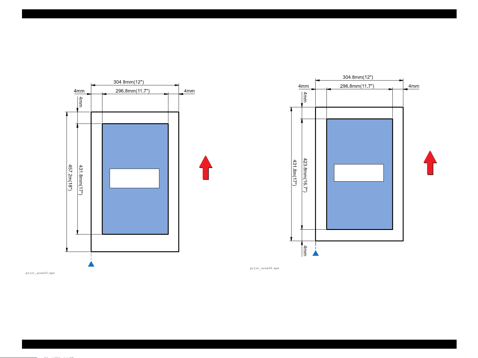
When Standard Universal Cassette is used
• Maximum paper size: 304.8 mm (12") (W) / 457.2 mm (18") (L)
• Printable area: 296.8 mm (11.7") (W) / 449.2 mm (17.7") (L)
• Guaranteed print area: 296.8 mm (11.7") (W) / 431.8 mm (17") (L)
Guaranteed Print
Area
When 500-Sheet Paper Cassette Unit / Large Capacity Paper Unit is used
• Maximum paper size: 304.8 mm (12") (W) / 431.8 mm (17") (L)
• Printable area: 296.8 mm (11.7") (W) / 423.8 mm (16.7") (L)
• Guaranteed print area: 296.8 mm (11.7") (W) / 423.8 mm (16.7") (L)
Paper Feed Direction
Paper Feed Direction
Guaranteed Print
Area
Side guide is here for paper whose width is 304.8 mm (12") or
Side guide is here for paper whose width is 304.8 mm (12") or
less
less
Figure 1-4. Maximum Printable Area
Figure 1-3. Maximum Printable Area (Standard Universal Cassette)
(500-Sheet Paper Cassette Unit / Large Capacity Paper Unit)
Product Description Basic Specifications 19
Page 29

EPSON AcuLaser C8600/AcuLaser C7000 Revision C
1.2.3 Reliability, Durability and Maintainability
MPBF
Printer body (including the standard tray (MSI)):
40,000 pages or more (100,000 images or more*)
Printer body (including the standard tray (MSI) and Duplex Unit):
40,000 pages or more (100,000 images or more*)
Printer body + 500-Sheet Paper Cassette Unit:
40,000 pages or more (100,000 images or more*)
Printer body + Large Capacity Paper Unit:
40,000 pages or more (100,000 images or more*)
Note "*": Since one page of color print is formed with 4 images, the value “100,000 images” is
calculated from the MPBF on the assumption that the job ratio of color printing to
monochrome printing is 1:1.
100,000 = 40,000/2 + (40,000/ 2 x 4)
PAPER FEED RELIABILITY
Standard Paper Tray
Recommended
Paper
Paper jam rate (simplex print)
Paper jam rate (duplex print)
Multiple-sheet feed rate
Note "*": Feeding reliability for envelopes is defined when printed on the front side at normal
temperature only. Envelopes that are adherent due to high temperature are excluded.
(Print on a back side is not guaranteed.)
1/1000 or less 1/500 or less 1/100
1/600 or less 1/300 or less -
1/1000 or less 1/1000 or less 1/50
Plain Paper
Standard Universal Cassette
Special
Applications*
500-Sheet Paper Cassette Unit / Large Capacity Paper Unit
Paper jam rate (simplex print)
Paper jam rate (duplex print)
Multiple-sheet feed rate
Recommended
Paper
1/5000 or less 1/3000 or less 1/100 or less
1/3000 or less 1/1800 or less 1/5000 or less 1/3000 or less 1/50 or less
Plain Paper
Special
Applications*
A3W Cassette
A3W Paper
Paper jam rate
Multiple-sheet feed rate
NOTE: The paper jam rate and multiple-sheet feed rate do not include those at
the sheets boundary between original paper and replenished paper,
occurring after paper is replenished.
1/2000 or less
1/500 or less
Paper jam rate (simplex print)
Paper jam rate (duplex print)
Multiple-sheet feed rate
Recommended
Paper
1/3000 or less 1/2000 or less 1/100 or less
1/1800 or less 1/1200 or less -
1/800 or less 1/500 or less 1/50 or less
Plain Paper
Special
Applications*
Product Description Basic Specifications 20
Page 30

EPSON AcuLaser C8600/AcuLaser C7000 Revision C
PRINTING START POSITION ACCURACY
Reference point of Main scanning direction (c) ±2.5 mm
Reference point of Sub scanning direction (a) ± 2.0 mm
Guaranteed Print
Area
Figure 1-5. Printing Start Position Accuracy
1.2.4 Operating Conditions (Including Consumables)
Temperature and Humidity Conditions
Temperature: 10 ∼ 32°C
Humidity: 15 ∼ 85%RH (no condensation, however)
Altitude
3,100 m or less
Level
Front-rear direction on the table: 5 mm or less (within 646 mm)
Paper Feed Direction
Right-left direction on the table: 10 mm or less (within 560 mm)
Lighting
3,000 lx or less (not to be exposed to direct sunlight)
Space Requirements
In order to ensure that the printer operates properly, provide at least as much space as
shown in Figure 1-6.
SKEW
Direction A4 (Landscape) A3
Main scanning direction (|c-d|)
Sub scanning direction (|a-b|)
SERVICEABILITY
MTTR: Averages within 30 minutes. 95% is completed within 50 minutes.
HEIGHT OF CURL OF PRINTED PAGES
±15 mm or less (for color printing with the image ratio of 5% in non- aligned
condition). (This value varies with the image ratio and aligning pattern.)
±1.5 mm (f=196 mm)
±2.0 mm (e=271 mm)
±3.0 mm (f=406 mm)
±2.0 mm (e=271 mm)
Product Description Basic Specifications 21
Page 31

EPSON AcuLaser C8600/AcuLaser C7000 Revision C
1.2.5 Storage and Transport of the Printer Body and Optional Products (Consumables Packaged)
150 mm
Ventilation
*1
728 mm
*2
633 mm
*1
825 mm
*2
730 mm
*1: With the Duplex Units installed
*2: Standard condition
Figure 1-6. Space Requirement
Ventilation
457 mm
780 mm
683 mm
835 mm
TEMPERATURE AND HUMIDITY CONDITIONS
Table 1-12. Temperature and Humidity Conditions
*
*
Warranty
Period
12 months
1 month max.
Temperature Humidity
Normal
conditions
Severe
Conditions
Note "*" : No condensation, however
High temperature: 35∼40 °C
Low temperature: -20∼0°C
0∼35 °C 15 ∼ 80%RH
*
High humidity: 80∼ 95%RH
Low humidity: 5∼15%RH
STORAGE BAROMETRIC PRESSURE (ALTITUDE)
0∼3,100 m
(0 to 15,000m is possible during air shipping, but the air pressure in the cargo room
must be 70.9275 kPa or more.)
DROPPING
Printer Body
Free drop
Height:
<Bottom]> 457 mm (18”)
<Other than bottom> 305 mm (12”)
Test times:
<Bottom> Once
<Other than bottom> Once for each face
(5 times in total)
Edge drop
Height: 457 mm (18”)
Test times: Once for each edge (4 times in total)
Product Description Basic Specifications 22
Page 32

EPSON AcuLaser C8600/AcuLaser C7000 Revision C
Optional Units
Dropping direction
1 corner, 3 edges, 6 sides
Dropping height
Table 1-13. Dropping Height
Optional Unit Height
Duplex Unit
500-Sheet Paper Cassette Unit
Large Capacity Paper Unit
A3W Cassette
VIBRATION
760 mm
760 mm
760 mm
920 mm
Frequency ................................ 2 ∼ 500Hz
Acceleration ............................ 12.6 m/s
2
(on the vibration board)
Direction of application ........... Three directions (x, y and z axes)*
Duration of application ............ 50 minutes
Note *1: Overall rms value
*2: X, Y: Vertical, Z: Horizontal
1.2.6 Electrical Features
Specifications here are not applicable to any optional units.
AC Line Noise
Pulse width: 50 ~ 1,000 ns
Pulse polarity: +/–
Repeat: Not synchronous
Modes: Common/normal
Voltage: 1kV
(However, the parts can withstand up to 2kv without
damage.)
Instantaneous Outages
DIP 100% (at rated voltage-10% and rated frequency-10%) for one cycle without
any effect on print quality.
Resistance to Static Electricity
*1
2
No possibility of any error which affects on print quality under the following
conditions:
Contact discharging: ±6kV
Atmospheric discharging: ±8kV
Inrush Current
1/2 cycle, 100 A or less, 10 msec or less
Insulation Resistance
10MΩ or more
Dielectric Strength
There is no breakdown when the following voltages are applied for one minute.
Table 1-14. Voltage to be Applied
Between
Primary Side and Chassis
100V/120V version
220V/240V version
AC2,000V
AC3,000V
Product Description Basic Specifications 23
Page 33

EPSON AcuLaser C8600/AcuLaser C7000 Revision C
Leak Current
100V: 0.25 mA or less
120V: 3.5 mA or less
220/240V: 3.5 mA or less
Conditions: 1.5kΩ, 0.15µF (between frames and non-charged metallic parts)
The measurement circuit is in compliance with IEC60960.
1.2.7 Process Specifications
Printer Type:
Dry electrophotographic with 2 ingredients using the intermediate belt transfer
system
Light Source:
Semi-conductor laser
Laser power: 5mW (rated)
Wave length: 785 nm +10/-15 nm (at 25°C)
Photoconductor Unit:
OPC drum (organic photoconductor)
Charging:
Roller transfer system
Development:
Exposed area development
Toner:
Non-magnetic toner with carrier
1st transfer:
Intermediate belt transfer system
2nd transfer:
Roller transfer system
Fusing:
Oil-less heat roller system
Density Adjustment:
Automatic (can not be set by user)
1.2.8 Compliance with Standards and Regulations
Safety Standards
100V/120V version
• UL1950 3rd Edition
• CSA C22.2 No.950-M95
220V/240V version
• IEC950 2nd Edition
• EN60950
• A3 by VDE with GS-mark
Safety Regulations (Laser Transmission)
100V/120V version
FDA21CFR Chapter 1, Subchapter J, Section 1010,1040
220V/240V version
IEC825 Class I Laser Product
NOTE:
EMI
120V (US): FCC Part15 SubpartB,
220/240V (Europe): EN 55022(CISPR Publication22), ClassB
Power Supply Harmonic
Complies with the power supply harmonic control guide line
Power Consumption
Conforms to International Energy Star Program standards
(30W or less in the low power mode)
Others
Toner: No effect on human health (OSHA, TSCA, EINECS)
Carrier: No effect on human health
OPC: No effect on human health (OSHA)
Ozone generation: UL478 (5th edition)
Laser power: 5mW (rated)
Wave length: 785 nm +10/-15 nm (at 25
ClassB (ANSI C63.4/11.4D)
Also, the printer main body meets the following
standards:
EN61000-3-2(Harmonics)
EN61000-3-3(Flicker)
°
C)
Product Description Basic Specifications 24
Page 34

EPSON AcuLaser C8600/AcuLaser C7000 Revision C
Materials: Swiss Environmental Protection Standards compliance
(contains no Cds)
1.2.9 Consumable Components
1.2.9.1 Consumables
TONER CARTRIDGES
C H E C K
P O I N T
Constitution and Life (Toner Consumption)
Toner Cartridge (Black) Black toner, etc. 5,500 images (Average) *
Toner Cartridge (Cyan) Cyan toner, etc. 6,000 images (Average) *
Toner Cartridge (Magenta) Magenta toner, etc. 6,000 images (Average) *
Toner Cartridge (Yellow) Yellow toner, etc. 6,000 images (Average) *
Note "*" : The number of images indicated here is defined on the assumption that the image
Dimensions and Weight
Unpacked
Packed
The Toner Cartridges for AcuLaser C8600/C7000 are not
interchangeable with those for EPL-C8000/8200.
The Toner Cartridges for AcuLaser C8600/C7000 are
interchangeable with those for AcuLaser C8500.
Table 1-15. Constitution and Life (Toner Consumption)
Name Constitution Life
ratio is 5% on A4 (LEF) paper during continuous printing, and does not represent the
number of pages for color printing. The life varies with the image ratio and printer
usage (whether continuous or intermittent).
<Dimensions> 50 mm (W) x 400 mm (D) x 54.5 mm (H)
<Weight> K 0.356 kg
Y/M/C 0.351 kg
<Dimensions> 85 mm (W) x 435 mm (D) x 0 mm (H)
<Weight> K 0.459kg
Y/M/C 0.474kg
NOTE: Tolerance for the dimension and weight is ± 1%.
Product Description Basic Specifications 25
Page 35

EPSON AcuLaser C8600/AcuLaser C7000 Revision C
Environmental Conditions for Storage and Transportation (common to all the
Toner Cartridges)
Temperature/humidity
Table 1-16. Temperature/Humidity
*1
1 month max.
Warranty
Period*
24 months
Temperature Humidity
Normal
conditions
Severe
conditions
Note *1: No condensation
*2: 12 months for unpacked cartridge under the conditions where the printer is used. (No
High temperature: 35∼ 40°C
Low temperature: -20∼ 0°C
condensation, however)
0∼35 °C 15∼ 80%RH
High humidity: 80∼ 95%RH
Low humidity: 5∼ 15%RH
*1
*1
Storage barometric pressure (altitude):
0 ~ 3,100m
(0 to 15000 m is possible during air shipping, but the air pressure in the cargo
room must be 70.9275 KPa or more.)
Drop test (packed):
<Height> .........................................910 mm
<Dropping direction>......................1 corner, 3 edges, 6 sides
Resistance to vibration (packed):
<Frequency> ...................................5 ~ 100Hz
<Acceleration>................................ 6.9 m/s
<Direction of application> .............. 3 directions (X, Y, Z)
<Duration of application>...............50 minutes for each direction
(150 minutes in total)
2
PHOTOCONDUCTOR UNIT
C H E C K
P O I N T
The Photoconductor Unit (Drum Cartridge) for AcuLaser C8600/
C7000 is not interchangeable with that for EPL-C8000/8200 or
AcuLaser C8500.
2
Constitution and Life
Constitution Life
• Photoconductor
•Drum Cleaner
• Waste Toner Box, etc.
Note "*" : The number of pages indicated here is defined on the assumption that A4 (LEF)
paper is used, the job ratio of monochrome printing to color printing is 1:1 and
printing is at 4P/J. The life varies with the image ratio and printer usage (whether
continuous or intermittent). The life by use at 1P/J is approximately 8,000 pages.
20,000 pages
The waste toner box has the same life
*
(Continuous printing)
B/W: 50,000 pages
Color: 12,500 pages
Life
Dimensions and Weight
Unpacked
<Dimensions> 213 mm (W) x 510 mm (D) x181 mm (H)
<Weight> 3.4 kg
Packed
<Dimensions> 318 mm (W) x 618 mm (D) x280 mm (H)
<Weight> 3.6 kg
NOTE: Tolerance for the dimension and weight is ± 1%.
Environmental Conditions for Storage and Transportation
Same as for Toner Cartridges
Product Description Basic Specifications 26
Page 36

EPSON AcuLaser C8600/AcuLaser C7000 Revision C
WASTE TONER BOX
C H E C K
P O I N T
The Waste Toner Box for AcuLaser C8600/C7000 is
interchangeable with those for EPL-C8000/8200 and AcuLaser
C8500.
Constitution and Life
Constitution Life
Waste Toner Box, etc. 20,000 pages
Note "*": The number of pages indicated here is defined on the assumption that the image ratio
is 5% on A4 (LEF) paper, the job ratio of monochrome printing to color printing is
1:1 and printing is at 4P/J. The life varies with the image ratio and printer usage
(whether continuous or intermittent).
*
B/W: 50,000 pages
Color: 12,500 pages
(Continuous printing)
Life
Dimensions and Weight
Unpacked
<Dimensions> 75.5 mm (W) x 444 mm (D) x 131 mm (H)
<Weight> 0.73kg
Packed
<Dimensions> 149 mm (W) x 495 mm (D) x 192 mm (H)
<Weight> 0.87kg
1.2.9.2 Regularly Replaced Parts
Without taking into account replacement by user, the periodical replacement parts for
this printer are as follows:
Main Fuser Assembly
100,000 pages
Exhaust Filter: 100,000 pages
NOTE: Tolerance for the dimension and weight is ± 1%.
Environmental Conditions for Storage and Transportation
Same as for Toner Cartridges
Product Description Basic Specifications 27
Page 37

EPSON AcuLaser C8600/AcuLaser C7000 Revision C
1.3 External View and Parts Names
1.3.1 External View and Parts Names
Symbol
a
b
c
d
e
f
g
h
i
j
k
l
m
n
o
p
q
Table 1-17. Parts Names
Name of Part
Control Panel
Cover A / EXIT UPPER COVER
(Output path cover)
FRONT COVER
Face-up Tray
Standard tray / MSI Tray / MP Tray
(Unit C)
Standard Universal Cassette / Lower
Cassette 1 (LC1)
RIGHT COVER
Unit C / MSI ASSY
(Paper path unit)
Parallel I/F Connector
Grounding Screw (2 positions)
Option Slot Cover (for Color Copy
Station)
Power Switch
AC Inlet
Fuser Unit / Unit B
Cover D / TURN CHUTE COVER
(Paper cassette cover)
Filter Assy
Option Slot Cover (for Type-B)
Symbol
r
s
t
u
v
w
x
y
z
A
B
C
D
E
F
G
Name of Part
USB I/F Connector
FRONT MID COVER
(Duplex unit slot cover)
Lower Cassette 2 / LC2 (Option)
Lower Cassette 3 / LC3 (Option)
Cover E / FEEDER CHUTE
ASSY
Unit B / DUP TRANSPORT
ASSY
INVERTER ASSY
Cover F / INVERTER ASSY
Unit G / DUPLEX UNIT
DUP TRANSPORT ASSY
Connector
INVERTER ASSY Connector
Large Capacity Paper Unit
Connector
Connector
Large Capacity Paper Unit
Logo Plate
500-Sheet Paper Cassette Unit
d
b
a
e
Figure 1-7. Top View
F
d
c
d
e
s
f
Figure 1-8. Front View
Product Description External View and Parts Names 28
Page 38

EPSON AcuLaser C8600/AcuLaser C7000 Revision C
a
Figure 1-9. Right Side View
b
j
k
g
q
h
o
i
j
r
p
Figure 1-11. Rear View
w
c
l
l
n
m
Figure 1-10. Left Side View
x
u
Figure 1-12. Front View
z
t
with Duplex Unit and Large Capacity Paper Unit Installed
Product Description External View and Parts Names 29
Page 39

EPSON AcuLaser C8600/AcuLaser C7000 Revision C
C
v
Figure 1-13. Right Side View
with Duplex Unit and Large Capacity Paper Unit Installed
A
B
E
n
w
y
D
E
Figure 1-15. Rear View
with Duplex Unit and Large Capacity Paper Unit Installed
G
Figure 1-14. Left Side View
with Duplex Unit and Large Capacity Paper Unit Installed
with 500-Sheet Paper Cassette Unit Installed
Figure 1-16. Front View
Product Description External View and Parts Names 30
Page 40

EPSON AcuLaser C8600/AcuLaser C7000 Revision C
1.3.2 Dimensional Drawing (in mm)
The dimensions of EPSON AcuLaser C8600/AcuLaser C7000 are shown below.
NOTE: The dimensions as shown below do not include ribs.
397 560 375
v
647
with 500-Sheet Paper Cassette Unit Installed
Figure 1-17. Right Side View
1332
Figure 1-18. Top View
650
554
Figure 1-19. Front View
Product Description External View and Parts Names 31
Page 41

EPSON AcuLaser C8600/AcuLaser C7000 Revision C
1425
742
680
818
with Large Capacity Paper Unit and Duplex Unit Installed
Figure 1-20. Overall Dimensions
Figure 1-21. Overall Dimensions
with 500-Sheet Paper Cassette Unit
(with Standard Castors) Installed
Figure 1-22. Overall Dimensions
with 500-Sheet Paper Cassette Unit
(with Supplied Rubber Feet) Installed
730
Product Description External View and Parts Names 32
Page 42

EPSON AcuLaser C8600/AcuLaser C7000 Revision C
1.4 Controller Specifications
1.4.1 Basic Controller Specifications
1.4.1.1 Basic Controller Specifications for AcuLaser C8600
CPU: PowerPC750CX (400MHz)
Enhanced Technology: AcuLaser Color Halftoning
CRIT, RIT (VIPS, CDMC)
RAM: SDRAM 64-bit width DIMM
(PC-100 or PC-133)
Maximum: 1024MB (with the standard RAM removed
and 512 MB of RAM installed in each of the 2 slots.
Up to 576 MB unless the standard RAM is removed)
2 slots (1 slot is used with standard RAM)
Standard: 64MB
Optional RAM: 64MB, 128MB, 256MB, 512MB
ROM: 32-bit width (3.3 V)
Program: 4MB (ROM DIMM)
Font: 4MB (ROM DIMM, Mask)
Expansion ROM: 2 slots (ROM DIMM slots, 3.3V, must be installed and
removed only with power turned off)
Slots A, B: Font ROM module, PostSccipt3 module, AcuLaser
Color Copy Station 8600 module
Control Panel: 1-line 20-digit LCD, 3 LEDs, 6 buttons
(control panel 2001)
Interfaces
Standard: Parallel 1ch
1EEE1284 compliant bi-directional
B-type connector
Compatibility, Nibble, ECP
USB (Rev.1.1) 1ch
Ethernet 100 Base-TX/10 Base-T 1ch
Optional: Type-B 1-slot (Level 3 compatible)
Dedicated interface for AcuLaser Color Copy Station
8600
HDD: 1 (the same option as for EPL-N2120)
Printer Settings: Control panel settings, EJL, PJL commands, and MIB
Storage cell: EEPROM serial type 16-kbyte
Printer Modes
Standard: ESC/Page-Color mode, ESC/Page(B/W) mode, LJ4
mode (B/W), GL2 mode (B/W), ESCP2 mode (B/W),
FX mode (B/W), I239X mode (B/W)
Optional: PostScript 3 (PostScript 3 module)
AcuLaser Color Copy Station 8600
Others: EJL, PJL mode
RCC mode
DIAG mode
Installation Method: Fixed to the printer body
1.4.1.2 Basic Controller Specifications for AcuLaser C7000
CPU: TMPR4955AF-200 MHz
Enhanced technology: AcuLaser Color Halftoning (supporting monochrome)
CRIT, RIT
RAM: 2 slots (1 slot for the standard RAM)
Standard: 32 MB, Maximum 256 MB
DIMM options: SDRAM DIMM dedicated to AcuLaser C1000/
AcuLaser C7000 (slot shape is different from PC slots)
16 MB, 32 MB, 64 MB and 128 MB
Program ROM: 2 MB (32-bit width)
EEPROM: 256-byte
Panel: 2 LEDs
Interfaces
Standard: Parallel interface 1 ch
IEEE1284 compatible bi-directional, B-Type connector
Compatibility, Nibble, ECP
USB 1.1 1ch
Options: Type-B 1 slot (compatible with Level-2)
However, currently Leo2.1 is only supported
Printer mode: ESC/PageS Printing System
Product Description Controller Specifications 33
Page 43

EPSON AcuLaser C8600/AcuLaser C7000 Revision C
1.4.2 Controller Configuration
The AcuLaser C8600/AcuLaser C7000 controller can set the following configurations.
Since jumper resistors are used for the settings, these settings are determined when the
printers are shipped from the factory.
1.4.2.1 Controller Configuration for AcuLaser C8600
NOTE: For AcuLaser C8600, controller configurations are A4 setting for all
markets, that is, LT setting is not used.
Table 1-18. Jumper Resisters for AcuLaser C8600
RJ401 RJ402 RJ403
Setting Item
Jumper
Resister
Table 1-19. Jumper Resister Factory Setting for AcuLaser C8600
For China
Other Countries
Mounted
Not mounted
N/W I/F Cassette Size Paper Size
Exist EXE LTR
Not exist B5 A4
RJ401 RJ402 RJ403
Mounted Not mounted Not mounted
Mounted Mounted Not mounted
1.4.3 Calibration Function (only with AcuLaser C8600)
AcuLaser C8600 has a calibration function. Calibration can be made by changing the
contents of the calibration table (1D) for AcuLaser C8600. Changing the contents of
the calibration table can be achieved by means of the Resource Data Control Code.
The default values in the calibration table are those set in the code area. After change,
however, the values stored in EEPROM will work as the values in the calibration table.
After change, the version information (date and time) of the changed calibration table
(for example, the table of gradation 600DPI) is indicated on the status sheet.
You must rewrite the Calibration Table only when necessary. Execute rewriting of the
Calibration Table according to the Calibration Table Data and rewriting procedure
given in Technical Information which is supplied separately.
C A U T I O N
This function is not described in manuals, that is, it is not disclosed
to users.
1.4.2.2 Controller Configuration for AcuLaser C7000
Table 1-20. Jumper Setting for AcuLaser C7000
JP100
Pattern Jumper
(INPT1)
Setting Item
Jumper Setting
Note: B5/EXE switching of paper cassettes is not available, and B5 is set for all markets.
1: Open
0: Short
Default setting for
MP tray paper size
A4 Other than Japan Nibble
LT Japan ECP
Product Description Controller Specifications 34
JP101
Pattern Jumper
(INPT3)
Setting for intended
market
JP102
DIC Jumper
(INPT7)
Parallel interface
receive mode
Page 44

EPSON AcuLaser C8600/AcuLaser C7000 Revision C
1.5 External Interface Specifications
<AcuLaser C8600>
AcuLaser C8600 is equipped with the external host interfaces as listed below:
Parallel interface (standard)
USB (Rev. 1.1) interfaces (standard)
Ethernet interface (standard)
Type-B host interface 1-slot (optional)
By installing the interface board for AcuLaser Color Copy Station 8600, the printer is
equipped with the AcuLaser Color Copy Station 8600 panel and scanner interface.
Figure 1-23 below shows the locations of the external interfaces of AcuLaser C8600.
Color Copy Station
interface
(Panel for Color Copy
Station and scanner)
Type-B (AUX)
interface
Parallel Interface
(IEEE1284 B-Type)
USB interface
LED: Link/Receive Lamp
(Green)
LED: 100Base-TX/10Base-T
Lamp (Orange)
Ethernet Interface
(100BaseTX/10BaseT
<AcuLaser C7000>
AcuLaser C7000 is equipped with the external host interfaces as listed below:
Parallel interface (standard)
USB (Rev. 1.1) interfaces (standard)
Type-B host interface 1-slot (optional)
Host interfaces' actual operations are limited to automatic interface switching only.
Figure 1-24 below shows the locations of the external interfaces of AcuLaser C7000.
Optional interface
Parallel interface
(IEEE1284 B-type)
USB interface
Figure 1-24. Locations of External Interfaces (AcuLaser C7000)
Backside View
Figure 1-23. Locations of External Interfaces (AcuLaser C8600)
Product Description External Interface Specifications 35
Page 45

EPSON AcuLaser C8600/AcuLaser C7000 Revision C
1.5.1 Parallel Interface Specifications
Interface Type
IEEE 1284 bi-directional high speed parallel interface
Operating Modes
Compatibility, Nibble, ECP
Connector Model Name
57RE-40360-830B (D7A) DDK or the equivalent
Conforming Plug
Amphenol or its equivalent
1.5.1.1 Parallel Interface Specifications for AcuLaser C8600
The initial Device ID value of AcuLaser C8600 is described below. Carriage returns
have been inserted into the list below to make it easier to read, but in actual practice the
device ID values are displayed as a continuous character string, and no carriage return
codes are inserted. The CMD parameters are not shown here in the actual order. None
of MODE and STATUS parameters is included. The DES parameter is a combination
of the MFG and MDL parameters with a space between them.
†
1
**
;
MFG:EPSON;
CMD:PJL,EJL,ESCPL2,ESCP9,PRPXL24-01,PCL,HPGL2-01,ESCPAGE-04,
ESCPAGECOLOR-01**
MDL:**
CLS:PRINTER;
DES:**
†
3
;
†
4
;
†
2
;
MDL:*****;
CLS:PRINTER;
DES:*****;
CID:*****;
1.5.1.2 Parallel Interface Specifications for AcuLaser C7000
Device ID values of AcuLaser C7000 are described below:
MFG:EPSON;CMD:ESCPAGES-02;MDL: AL-C7000;CLS:PRINTER;DES:EPSON AL-C7000;
Communication modes are switched with the jumper switch on the controller board.
Nibble: The ECP communication mode is not supported, and the Reverse
mode is only available in the Nibble communication mode
ECP: The ECP communication is supported (ECP is the default
specification)
†1: “Total number of characters + 2" of the device ID appears in hexadecimal.
†2: “POSTSCRIPT” is added only when the PostScript 3 module is installed.
†3: The model name appears AL-C8600
†4: The manufacturer and model name appears EPSON AL-C8600
Furthermore, the user can redefine the Device ID MFG, MDL, DES and CID.
Also, the CID Field does not respond with the default value, but does respond with the
defined character string only when it has been redefined. The Device ID when
redefined is as follows. The asterisks “*****” are the user defined character strings.
MFG:*****;
CMD:PJL,EJL,ESCPL2,ESCP9,PRPXL24-01,PCL,HPGL2-01,ESCPAGE-04,
ESCPAGECOLOR-01**†2;
Product Description External Interface Specifications 36
Page 46

EPSON AcuLaser C8600/AcuLaser C7000 Revision C
1.5.2 USB Interface Specifications
The USB interface is in compliance with the Universal Serial Bus specification
Rev. 1.1.
Difference from Rev. C:
Rev. 1.1 replies to the following requests without rejecting:
CLEAR_FEATURE Endpoint0
GET_STATUS Endpoint0
AcuLaser C8600/AcuLaser C7000 has an 18-digit serial ID number for USB Rev. 1.1.
This ID number is displayed at the bottom of the Status Sheet. Each digit denotes the
information as described below.
1, 2: Number from 00 to 99 specific to model
(“09” for AcuLaser C8600/“13” for AcuLaser C7000)
3: P for page printer
4, 5: PC number on the assembly belt
6, 7: Year of assembly
8, 9: Month of assembly
10, 11: Day of assembly
12, 13: Hour of assembly
14, 15: Minute of assembly
16, 17: Second of assembly
18: Reserved digit (0 is normally specified)
C A U T I O N
If the circuit board is replaced for maintenance services or some
other reason, the USB serial number must be changed to another
USB ID. Consequently, the printer may be recognized as a
different printer when it is connected to the computer.
1.5.3 Ethernet Interface
Interface type
10Base-T, 100BaseT-X, Half Duplex, Full Duplex (Switched at power on)
Printing protocols
TCP/IP....................... LPR, FTP, IPP, PORT2501, PORT9100
Microsoft Network ... SMB
NetWare
Operating mode
Standby (factory default), NDS Print Server, Bindery Print Server, Remote
Printer)
AppleTalk
Management protocols
TCP/IP................ SNMP, ENPC, HTTP, TELNET, DHCP, BOOTP, PING
Microsoft Network ... Auto-IP, SSDP
NetBEUI ................... SNMP, ENPC
NetWare .................... SNMP, ENPC
AppleTalk ................. SNMP, ENPC
NOTE a: ENPC: EPSON Network Peripheral Control Protocol
b: IPP: Internet Printing Protocol
Connector type: RJ45
Applicable cable: 2-pair STP (10Base-T, 100Base-TX)
NOTE: In order to conform to FCC Class B, EN55022 Class B, and VCCI Class
B, a shielded type cable must be used.
Product Description External Interface Specifications 37
Page 47

EPSON AcuLaser C8600/AcuLaser C7000 Revision C
Pin configuration
See Table 1-21.
Table 1-21. Pin Configuration for the Ethernet I/F
Pin Signal Name I/O
1 Tx+ O
2 Tx- O
3 Rx+ I
4 N.C. -
5 N.C. -
6 Rx- I
7 N.C. -
8 N.C. -
Entity type
See Section 1.5.4 "Type-B Interface Specifications".
1.5.4 Type-B Interface Specifications
AcuLaser C8600/AcuLaser C7000 has one Type-B optional interface slot as standard
equipment.
1.5.4.1 Type-B Interface Specifications for AcuLaser C8600
Main System Type:
MTP600dpi,PW7748dt600dpi,PRG(*****)rev,AP800ma,SPD0fast,D4
NOTE: The asterisks***** represent the ROM version.
Printer Name:
Factory default Printer Name is the same as the Product Name.
Product Name: AL-C8600
Emulation Type: See the table below
Entity Type: See the table below
Table 1-22. Emulation Type/Entity Type
Emulation Emulation Type Entity Type
*1
PS
ESC/Page Color ESCPAGECOLOR-01 EPSONPAGECOLOR1
ESC/Page ESCPAGE-04
LJ4 PCL5E-00 EPSONPCL5
1239X PRPXL24-01 EPSONPRPXL24
GL2 HPGL2-01 EPSONHPGL2
FX ESCP9 EPSONFX
ESCP2 ESCPL2 EPSONLQ2
POSTSCRIPT-00
*1
LaserWriter
*1
Note: *1: Added when a PostScript 3 module is installed.
Emulation Type:
When Emulation is set to AUTO;
If PS is not started: AUTO (Emulation Types 1, 2, 3, . . .)
If PS is started: EJL (POSTSCRIPT-00, other Emulation
Types 1, 2, 3, . . .)
When Emulation is fixed: EJL (Default Emulation Type, other
Emulation Types 1, 2, 3, . . .)
Product Description External Interface Specifications 38
Page 48

EPSON AcuLaser C8600/AcuLaser C7000 Revision C
Entity Type:
When Emulation is set to AUTO:Refer to the above list.
When Emulation is fixed: The default Emulation Type and
EPSONPAGECOLOR1 are returned.
1.5.4.2 Type-B Interface Specifications for AcuLaser C7000
Applicable Type-B optional interface is Leo2.1 only.
Main System Type: MTP600dpi,PW7748dt600dpi,PRG(*****)rev,
AP800ma,SPD0fast,GDI
***** is a ROM version
Printer Name: AL-C7000
Product Name: AL-C7000
Emulation Type: ESCPAGES-02
Entity Type: EPSONPAGES2
Product Description External Interface Specifications 39
Page 49

EPSON AcuLaser C8600/AcuLaser C7000 Revision C
1.6 Control Panel (AcuLaser C8600)
1.6.1 External View and Names
LCD Panel
1 line, 20 characters
(5x 7 dot matrix)
LCD (20 digits)
Back button
Figure 1-25. External View of Control Panel (AcuLaser C8600)
NOTE: Enter button, Back button, Up button and Down button can be used for
password input. The key assignment of password, which is shown on the
label, is as follows:
Enter button:3
Back button:1
Up button:2
Down button:4
Enter button
Up button
Down button
Data LED (Yellow)
Job Cancel button
Ready LED (Green)
Error LED (Red)
Start/Stop button
1.6.2 Description of Indicators
LCD PANEL
One-line 20-character (5 x 7 dot matrix) liquid crystal display
Normally displays printer status.
In panel setting mode, LCD displays setting menus, setting items or setting
values.
READY LED
On: The printer is On Line.
Off: The printer is in a pause status.
If any error occurs, the printer goes into a pause status, with the Ready LED
going out.
DATA LED
On: Printer contains data that has not been processed yet.
Off: No effective print data remains in the printer.
Blinking: The printer is processing data now.
ERROR LED
Blinking1: An error has occurred which permits continuing to print by
pressing the Continue button.
When “Auto Cont” is ON, error status will be automatically
cleared after a while even without pressing the Start/Stop button.
Example: “Paper Set” error
On: An error has occurred which does not permit the printer to
recover without its clearing by the user.
Clearing the error will automatically recover the printer.
Example: “Front Cover Open” error
Blinking 2: An error has occurred which requires the user to clear the error
and press the Start/Stop button.
Setting “Auto Cont” to “ON” will not affect this error.
Example: “Multi-bin Paper Eject Full” error
NOTE: Blinking 1 repeats a cycle of 0.3-second ON and 0.3-second OFF.
Blinking 2 repeats a cycle of 0.6-second ON and 0.6-second OFF.
Product Description Control Panel (AcuLaser C8600) 40
Page 50

EPSON AcuLaser C8600/AcuLaser C7000 Revision C
1.6.3 Description of Buttons
START/STOP BUTTON
In normal operation:
Pressing this button interrupts or resumes printing operation. Pressing the
button will change the state of the Ready LED between ON and OFF
alternately.
Pressing this button after start of printing operation will stop printing after
completion of the printing of the currently printed page.
Another pressing of this button resumes printing.
NOTE: Even when the Ready LED is off and thus printing is not performed, other
operations are kept on. This means that data receive is continued until
the receive buffer is filled up to its full capacity.
When this button is pressed for an extended period of time with the printer in
the pause status:
The printer ejects paper forcibly if it has print data.
When any error has occurred:
• If the error permits the printer to recover only by pressing the button:
Pressing this button clears the error and turns off the Error LED.
• If the error does not permit the printer to recover only by pressing the button:
Pressing this button does not change the state of the Error LED but changes
the LCD indication to “Unable Clear Error”.
JOB CANCEL BUTTON
• Pressing normally:
Deletes the currently printed data.
Each pressing deletes one job.
• Pressing for 2 seconds or longer:
Deletes all of the data in the printing queue, the job and data currently
received and the data currently printed.
In panel setting mode:
The printer displays the next lower rank in the hierarchical setting system.
The setting value is registered or the selected item is executed.
BACK BUTTON
In normal operation:
The printer enters the panel setting mode.
In panel setting mode:
The printer displays the previous higher rank in the hierarchical setting
system.
When this button is pressed in the top rank (menu) in the hierarchy, the printer
leaves the panel setting mode to return to the normal operation mode.
UP BUTTON
In normal operation:
The printer enters the panel setting mode.
In panel setting mode:
Displays the previous value of the currently selected rank (menu, item or
setting value) in the hierarchy.
DOWN BUTTON
In normal operation:
The printer enters the panel setting mode menu.
In panel setting mode:
Displays the next value of the currently selected rank (menu, item or setting
value) in the hierarchy.
ENTER BUTTON
In normal operation:
The printer enters the panel setting mode.
Product Description Control Panel (AcuLaser C8600) 41
Page 51

EPSON AcuLaser C8600/AcuLaser C7000 Revision C
Functions of Buttons
Table 1-23. Summary of Button Functions
Button Name On Line In Pause Status Error Has Occurred In Panel Setting Mode
Ready Into pause status
1. Pressing normally:
Job Cancel
Enter
Back
Up
Down
Deletes printing data
2. Pressing for 2 seconds or longer:
Deletes all printing data
Enters the printer information menu in
the panel setting mode
Enters the printer information menu in
the panel setting mode
Enters the printer information menu in
the panel setting mode
Enters the printer information menu in
the panel setting mode
1. Pressing normally:
Into On Line status
2. Pressing for 2 seconds or longer:
Ejects paper forcibly
1. Pressing normally:
Deletes printing data
2. Pressing for 2 seconds or longer:
Deletes all printing data
Enters the printer information menu in
the panel setting mode
Enters the printer information menu in
the panel setting mode
Enters the printer information menu in
the panel setting mode
Enters the printer information menu in
the panel setting mode
1. Recoverable error:
Clears error
2. Non-recoverable error:
Displays “Unable Clear Error”
1. Pressing normally:
Deletes printing data
2. Pressing for 2 seconds or longer:
Deletes all printing data
Invalid
Invalid
Invalid
Invalid
Returns to normal mode (the same state as before
entering panel setting mode)
Invalid
1. When panel setting mode menu is displayed:
Displays setting item
2. When setting item for non-execution is displayed:
Displays setting value
3. When setting item for execution is displayed:
Executes printing or processing
4. When setting value is displayed:
Registers the setting value
1. When panel setting mode menu is displayed:
Returns to normal mode
2. When setting item or setting value is displayed:
Displays the previous higher rank in hierarchy
1. When panel setting mode menu is displayed:
Displays the previous panel setting mode menu
2. When setting item is displayed:
Displays previous setting item
3. When setting value is displayed:
Displays previous setting value
1. When panel setting mode menu is displayed:
Displays the next panel setting mode menu
2. When setting item is displayed:
Displays next setting item
3.When setting value is displayed:
Displays next setting value
Product Description Control Panel (AcuLaser C8600) 42
Page 52

EPSON AcuLaser C8600/AcuLaser C7000 Revision C
1.6.4 Operation and Indications on the Control Panel
Switching between On Line and Pause Status:
Switched alternately by pressing the Start/Stop button.
Switching is impossible when any error has occurred.
Forced Paper Eject:
In a Pause Status, hold down the Start/Stop button for 2 seconds or longer.
Upon 2-second pressing, the printer displays “Form Feed”.
Upon release of the button, if it has printing data, the printer prints one page by the
specified number of sheets.
Even when the control code has not been terminated for the receive data, the data
that has been received will be printed.
Upon release of the button, if the printer does not have printing data, the display
“Form Feed” will go out.
The Ready LED remains OFF, without change in its state.
When any error has occurred, pressing the Start/Stop button is invalid, so that
forced paper eject will not be executed.
Clearing “Warning”:
Execute “xxx Warning clear” in the panel setting mode. Then the relevant
“Warning” and all the other “Warning”, if any, will be cleared.
Clearing “Error”
Error LED Blinking 1:
Cleared by pressing the Start/Stop button. When “Auto Cont” is ON, error
status will be automatically cleared after a while even without pressing the
Start/Stop button.
Error LED On:
When the Start/Stop button is pressed with the Error LED lighting, the LCD
indication changes to “Unable Clear Error”.
Take an appropriate corrective action, and the printer will automatically clear
“Error” status.
Error LED Blinking 2:
Take an appropriate corrective action and then press the Start/Stop button, so
that the “Error” status will be cleared.
If the appropriate corrective action is not taken, the same error occurs again.
Setting “Auto Cont” to “ON” will not affect this error.
Deleting the Printing Data:
Press the Job Cancel button.
The display shows “Cancel Print Job”.
Each pressing deletes one of the printing data. However, pressing the Job Cancel
button is invalid as long as “Cancel Print Job” is being displayed.
Upon completion of deletion, the printer enters into the On Line status.
In the panel setting mode, pressing the Job Cancel button is invalid.
Clear any of the following errors resulting from printing data after deleting the
printing data.
• Check Paper Size
• Check Transparency
• Check Paper Type
• Irregular Density
• Manual Feed ssss tttt
• Can't Print Duplex
• Paper Out ssss tttt
• Paper Set ssss tttt
• uuuu Toner Out
• Print Overrun
• Mem Overflow
• Duplex Mem Overflow
Deleting All the Printing Data:
Hold down the Job Cancel button for 2 seconds or longer.
The display shows “Cancel All Print Job”.
Stored Job is not deleted.
Upon completion of deletion, the printer enters into the On Line status.
<For reference only>
When the top page of the unprinted data is contained in a job, all the job is deleted.
When the top page of the unprinted data is not contained in a job, deletion will be
continued until a lapse of about 10 seconds after the end of data or until just before the
start of the next job.
The LCD shows “Cancel Print Job” just when the Job Cancel button is pressed. And
when you release the button, the printer will delete the data currently printed.
The page being printed just when the Job Cancel button is pressed will be printed and
output.
Reset All:
Execute “Reset All” in the panel setting mode.
Execute “Reset” in the panel setting mode.
Product Description Control Panel (AcuLaser C8600) 43
Page 53

EPSON AcuLaser C8600/AcuLaser C7000 Revision C
Panel Setting
Transition to panel setting mode:
Press one of the Back, Up, Down and Enter buttons.
The printer enters the first setting menu.
The display shows “v setting menu”.
“v” means that the setting can be changed by the Up or Down button.
NOTE: When any error has occurred, transition to the panel setting mode can
not be made.
Changing the setting menu:
Press the Up or Down button with the setting menu displayed.
Pressing the Down button displays the next menu.
Pressing the Up button displays the previous menu.
Transition to display of setting item:
Press the Enter button with the setting menu displayed.
The display shows “v Setting Item = setting value”.
For an execution item, the display shows “v Setting Item”.
Pressing the Back button returns the display to setting menu.
Changing the setting item:
Press the Up or Down button with the setting item displayed.
Executing the setting item:
Press the Enter button with “v Setting Item” displayed.
The printer will execute processing and return to the same status as it was
before entering the panel setting mode.
Transition to display of setting value:
Press the Enter button with the setting item displayed.
The display shows “Setting Item = v setting value”.
Pressing the Back button returns the display to the setting item.
Changing the setting value:
Press the Up or Down button with the setting value displayed.
Pressing the Up button will increment the numerical value, while pressing the
Down button will decrement it.
Pressing the Up button will display the previous character, while pressing the
Down button will display the next character.
Registering the setting value:
Press the Enter button with the setting value displayed.
The setting value will be registered and the display will return to “v Setting
Item = setting value”.
The setting value of this display means the registered value.
Leaving the panel setting mode:
Press the Start/Stop button, or press the Back button with the setting menu
displayed.
Product Description Control Panel (AcuLaser C8600) 44
Page 54

EPSON AcuLaser C8600/AcuLaser C7000 Revision C
1.6.5 Panel Setting Item List
This section describes setting items for AcuLaser C8600.
Values shown in bold and underlined characters are the factory default setting values.
Each item of Menu, Item, and Value is applicable when “Lang = English” is set.
Table 1-24. Panel Setting Item List (1)
Menu Item Value
Information Menu
Status Sheet
Reserve Job List
Form Overlay List
*2
NetworkStatus
*3
Sheet
AUX Status Sheet
*4, *5
PS3 Status Sheet
PS3 Font Sample *
ESC/Page Font
*7
Sample
LJ4 Font Sample
ESCP2 Font Sample
FX Font Sample
I239X Font Sample
C Toner
*8
M Toner
Y Toner
*8
K Toner
Photocondctr
Total Pages
Color Pages
B/W Pages
*1
*6
6
E****F, E***F, E**F, E*F, E F
*8
E****F, E***F, E**F, E*F, E F
E****F, E***F, E**F, E*F, E F
*8
*8
*8
*8
E****F, E***F, E**F, E*F, E F
*8
E****F, E***F, E**F, E*F, E F
0 ∼ 99999999
0 ∼ 99999999
0 ∼ 99999999
Table 1-24. Panel Setting Item List (1) (continued)
Menu Item Value
Note *1: Displayed only when a Job is registered in the Quick Print Job.
*2: Displayed only when the Form Overlay is implemented.
*3: Displayed only when starting up with the setting Network Menu → Network
I/F = On
*4: Displayed only when the printer is equipped with Type-B Level 3.
*5: Displayed only when starting up with the setting AUX Menu → AUX I/F =
On.
*6: Displayed only when the PostScript 3 module is installed.
*7: This is not displayed on the control panel. It can be executed in EJL.
*8: This item is only displayed, so that its setting can not be changed.
Tray Menu
MP Tray Size
LC1 Size
LC2 Size *2,
LC3 Size *2,
*2
*3
*4
MP Type Plain, Letterhead, Recycled, Color, Trnsprncy, Labels
LC1 Type Plain, Letterhead, Recycled, Color
LC2 Type*3 Plain, Letterhead, Recycled, Color
LC1 Type*4 Plain, Letterhead, Recycled, Color
Note *1: This item depends on the factory default paper size of the controller
configuration.
*2: This item is only displayed, so that its setting can not be changed.
*3: Displayed only when the Large Capacity Paper Unit or 500-Sheet Paper
Cassette Unit is installed.
*4: Displayed only when the Large Capacity Paper Unit are installed.
*5: This item depends on the paper size (EXE/B5) for paper cassette of the
controller configuration.
A4 *1, A3, A5, B4, B5, LT *1, HLT, LGL, GLT, GLG,
B, EXE, F4, MON, C10, DL, C6, IB5, A3W
When installing the standard 250 sheets cassette: A4,
A3, B4, B5 *5, LT, LGL, B, EXE
*5
A4, A3, B4, B5 *5, LT, LGL, B, EXE
A4, A3, B4, B5 *5, LT, LGL, B, EXE
*5
*5
Product Description Control Panel (AcuLaser C8600) 45
Page 55

EPSON AcuLaser C8600/AcuLaser C7000 Revision C
Table 1-24. Panel Setting Item List (1) (continued)
Menu Item Value
Emulation Menu
Parallel Auto, LJ4, ESCP2, FX, I239X, PS3
USB Auto, LJ4, ESCP2, FX, I239X, PS3
Network Auto, LJ4, ESCP2, FX, I239X, PS3
*2
AUX
Note *1: Displayed only when the PostScript 3 module is installed.
*2: Displayed only when the Type-B interface card is installed.
Printing Menu
Page Size
Wide A4 Off, On
Orientation Port, Land
Resolution 600, 300
RITech On, Off
Toner Save Off, On
Image Optimum Auto, Off, On
Top Offset -99.0 ~ 0.0 ~ 99.0 mm step 0.5 mm
Left Offset -99.0 ~ 0.0 ~ 99.0 mm step 0.5 mm
T Offset B
L Offset B
*2
*2
Note *1: This item depends on the factory default paper size of the controller
configuration.
*2: Displayed only when the optional duplex print unit is installed.
*3: The paper size of CTM is minimum 90 × 139.7 mm, maximum 328 × 453mm.
Auto, LJ4, ESCP2, FX, I239X, PS3
A4 *1, A3, A5, B4, B5, LT *1, HLT, LGL, GLT, GLG,
B, EXE, F4, MON, C10, DL, C6, IB5, CTM *3, A3W
-99.0 ~ 0.0 ~ 99.0 mm step 0.5 mm
-99.0 ~ 0.0 ~ 99.0 mm step 0.5 mm
*1,
*1,
*1,
*1,
GL2
GL2
GL2
GL2
Table 1-24. Panel Setting Item List (1) (continued)
Menu Item Value
Setup Menu
Lang
Lang
Sprache
LINGUA
LENG
SPRAK
Sprog
Taal
KIELI
Ling)
Time Out 0, 5 ~ 60 ~ 300 step 1
Paper Source Auto, MP, LC1, LC2 *1, LC3
Out Bin Face-down, Face-up
MP Mode Normal, Last
Manual Feed Off, On
Copies 1 ~ 999
Quantity
Duplex
Binding
Start Page
*3
*4
*4
*4
Paper Type Normal, Thick, ExtraThk, Trnsprnc, Coated
Page Side Front, Back
Skip Blank Page *5Off, On
Auto Eject Page Off, On
Size Ignore Off, On
Auto Cont Off, On
Page Protect Auto, On
LCD Contrast 0 ~ 9 ~ 15
Panel Lock
*6
English
Francais
Deutsch
ITALIANO
ESPANOL
SVENSKA
Dansk
Nederl.
SUOMI
Portugues
1 ~ 999
Off, On
Long Edge, Short Edge
Front, Back
Off, On
*2
Product Description Control Panel (AcuLaser C8600) 46
Page 56

EPSON AcuLaser C8600/AcuLaser C7000 Revision C
Table 1-24. Panel Setting Item List (1) (continued)
Menu Item Value
Note *1: This item is displayed only when the Large Capacity Paper Unit or 500-Sheet
Paper Cassette Unit is installed.
*2: Displayed only when the Large Capacity Paper Unit are installed.
*3: This is not displayed on the control panel, and is not printed on the Status Sheet
ether. It can be set in EJL or PJL. It is not stored in NVRAM.
*4: Displayed only when the optional duplex print unit is installed.
*5: Valid in ESC/Page, PCL5e, ESC/P2, FX and I239X modes.
*6: This is not displayed on the control panel, and is not printed on the Status Sheet
ether. It can be set in EJL.
Quick Print
JobMenu
ConfidentialJobMenu
*1
User xxxxxxxxxxxxxx
*2
Job
*3
Copies
Delete *3,
*4
xxxxxxxxxxxxxxx
1 ~ 999
Note *1: This menu is not displayed when nothing is registered in the Verify Job, Re-
print Job, and Stored Job.
*2: This item appears only when selecting Quick Print Job Menu → User = <User
name>.
*3: This item appears only when selecting Quick Print Job Menu → Job = <Job
name>. After executing this item, the printer returns to the status when
recovering from the SelecType mode.
*4: After executing this item, the printer returns to Quick Print Job Menu → Job.
If available Job is not exist, the printer returns to Quick Print Job Menu
User. If available User is not exist, the printer returns to the status when
recovering from the SelecType mode.
*1
User xxxxxxxxxxxxxx
Enter Password
*3
Job
Copies
Delete *4,
*2
XXXX
*4
*5
xxxxxxxxxxxxxxx
1 ~ 999
→
Table 1-24. Panel Setting Item List (1) (continued)
Menu Item Value
Note *1: This menu is not displayed when nothing is registered in the Confidential Job.
*2: This item appears only when selecting Confidential Job Menu → User = <User
name>. A password can be input by means of the 1 (Back), 2 (Up), 3 (Enter),
and 4 (Down) buttons.
*3: After entering a Confidential Job Menu → Enter Password = <Password>, this
item appears if a job matching the password exists.
*4: This item appears only when selecting Confidential Job Menu → Job = <Job
name>. After executing this item, the printer returns to the same status as it has
left the SelecType mode.
*5: After executing this item, the printer returns to Quick Print Job Menu → Job.
If no Job available exists, the printer returns to Quick Print Job Menu → User.
If no User available exists, the printer returns to the same status as it has left the
SelecType mode.
Reset Menu
Clear Warning
Reset
Reset All
SelecType Init
Parallel Menu
Note *1: The interface setting is reflected immediately to the Status Sheet and EJL read-
USB Menu
Note *1: The interface setting is reflected immediately to the Status Sheet and EJL read-
*1
Parallel I/F On, Off
Speed Fast, Normal
Bi-D Nibble, ECP, OffF
Buffer Size Normal, Maximum, Minimum
back, but the setting is not effective just after it is changed. The changed setting
becomes valid in practice after warm boot or restarting the printer.
*1
USB I/F On, Off
Buffer Size Normal, Maximum, Minimum
back, but the setting is not effective just after it is changed. The changed setting
becomes valid in practice after warm boot or restarting the printer.
Product Description Control Panel (AcuLaser C8600) 47
Page 57

EPSON AcuLaser C8600/AcuLaser C7000 Revision C
Table 1-24. Panel Setting Item List (1) (continued)
Menu Item Value
Network Menu
Note *1: The interface setting is reflected immediately to the Status Sheet and EJL read-back,
*2: After switching to “On Line”, the value is automatically changed to “No”.
*3: This item appears only when “Network Menu → Network Config = Yes” is set.
*4: This item does not appear when “Network Menu → Get IPAddress = Auto” is set.
*1
Network I/F On, Off
Network Config *2No, Yes
*3, *4
*3, *4
3, *4
3, *4
*3
Panel, Auto, PING
0 ~ 192 ~ 255
0 ~ 168 ~ 255
0 ~ 192 ~ 255
0 ~ 168 ~ 255
3
3
3
3
3
3
3
3
0 ~ 255
0 ~ 255
0 ~ 255
0 ~ 255
0 ~ 255
0 ~ 255
0 ~ 255
0 ~ 255
Get IPAddress
IP Byte 1
IP Byte 2
IP Byte 3 *
IP Byte 4 *
SM Byte 1 *
SM Byte 2 *
SM Byte 3 *
SM Byte 4 *
GW Byte 1*
GW Byte 2 *
GW Byte 3 *
GW Byte 4 *
Buffer Size Normal, Maximum, Minimum
but the setting is not effective just after it is changed. The changed setting becomes
valid in practice after warm boot or restarting the printer.
Table 1-24. Panel Setting Item List (1) (continued)
Menu Item Value
AUX Menu *1,
*2
AUX I/F On, Off
*4
*4
*6
4, *5
4, *5
4, *5
4, *5
4
4
4
4
4
*4
*3
No, Yes
*4
Panel, Auto, PING
0 ~ 255
0 ~ 255
0 ~ 255
0 ~ 255
0 ~ 255
0 ~ 255
0 ~ 255
0 ~ 255
0 ~ 255
4
4
4
0 ~ 255
0 ~ 255
0 ~ 255
On, Off
On, Off
On, Off
AUX Config
Get IPAddress
IP Byte 1 *
IP Byte 2 *
IP Byte 3 *
IP Byte 4 *
SM Byte 1 *
SM Byte 2 *
SM Byte 3 *
SM Byte 4 *
GW Byte 1*
GW Byte 2 *
GW Byte 3 *
GW Byte 4 *
NetWare
AppleTalk
NetBEUI
AUX Init
Buffer Size Normal, Maximum, Minimum
Product Description Control Panel (AcuLaser C8600) 48
Page 58

EPSON AcuLaser C8600/AcuLaser C7000 Revision C
Table 1-24. Panel Setting Item List (1) (continued)
Menu Item Value
Note *1: Displayed only when the Type-B interface card is installed.
*2: The interface setting is reflected immediately to the Status Sheet and EJL read-
back, but the setting is not effective just after it is changed. The changed setting
becomes valid in practice after warm boot or restarting the printer.
*3: Displayed only when the printer is equipped with Type-B Level 3 host
interface. After switching to “On Line”, the value is automatically changed to
“No”.
*4: Displayed only when the printer is equipped with Type-B Level 3 host
→ AUX Config = Yes” is set.
→ AUX Config = Yes” is set.
*5: This item does not appear when “AUX Menu → Get IPAddress = Auto” is set.
*6: Displayed only when the printer is equipped with Type-B Level 3 host
ESC/Page Menu
interface. It appears only when “AUX Menu
This setting depends on the Type-B Level 3 board setting. The setting value
shifts to On Line status, and becomes effective when the network card restarts.
Therefore even after changing the setting value, the previous setting value can
be output if you execute “AUX Status Sheet” in the Information Menu before
exiting from the panel setting mode.
interface. It appears only when “AUX Menu
*1
Auto CR On, Off
Auto FF On, Off
CR Function CR, CR+LF
LF Function CR+LF, LF
FF Function CR+FF, FF
Error Code Ignore, Space
Avoid Error Off, On
PGI
On, Off
TriColorSpace Normal, sRGB
CM Media Type Off, Opt1, Opt2
Table 1-24. Panel Setting Item List (1) (continued)
Menu Item Value
LJ4 Menu
FontSource Resident, Download *1, ROM A *2, ROM B
Font Number 0 ~ availableÅiMax 65535Åj
*3
Pitch
*3
Height
SymSet
Form 5 ~ 60 *5 ~ 64 *5 ~ 128 Lines
Source SymSet 0 ~ 277 ~ 3199
Dest SymSet 0 ~ 277 ~ 3199
CR Function CR, CR+LF
LF Function LF, CR+LF
Tray Assign 4, 4K, 5S
0.44 ~ 10.00 ~ 99.99 cpi step 0.01cpi
4.00 ~ 12.00 ~ 999.75 pt step 0.25 pt
IBM-US, Roman-8, Roman-9, ECM94-1, 8859-2 ISO,
8859-9 ISO, 8859-10ISO, 8859-15ISO, PcBlt775, IBMDN, PcMultiling, PcE.Europe, PcTk437, PcEur858,
Pc1004, WiAnsi, WiE.Europe, WiTurkish, WiBALT,
DeskTop, PsText, VeInternati, VeUS, MsPublishin,
Math-8, PsMath, VeMath, PiFont, Legal, UK, ANSI
ASCII, Swedis2, Italian, Spanish, German, Norweg1,
French2, Windows, McText, PcIcelandic
*4
PcTurk1
, PcPortugues *4, PcEt850 *4, PcTurk2 *4,
PcCanFrench *4, PcSl437 *4, PcNordic *4, 8859-3 ISO *4,
8859-4 ISO *4, WiBaltic *4, WiEstonian *4, WiLatvian
*4
, Mazowia *4, CodeMJK *4, BpBRASCII *4,
BpAbicomp *4, PcGk437 *4, PcGk851 *4, PcGk869 *4,
*4
8859-7 ISO
, WiGreek *4, Europe3 *4, PcCy855 *4,
PcCy866 *4, PcLt866 *4, PcUkr866 *4, PcLit771 *4,
8859-5 ISO *4, WiCyrillic *4, Bulgarian *4, Hebrew7 *4,
*4
8859-8 ISO
, Hebrew8 *4, PcHe862 *3, Arabic8 *4,
PcAr864 *4, 8859-6 ISO *4, OCR A *4, OCR B
*2
*4
, PcLt774 *4,
*4
Note *1: This is not displayed on the control panel, and is not printed on the Status Sheet
ether. It can be set in EJL.
Product Description Control Panel (AcuLaser C8600) 49
Page 59

EPSON AcuLaser C8600/AcuLaser C7000 Revision C
Table 1-24. Panel Setting Item List (1) (continued)
Menu Item Value
Note *1: Displayed only when some download fonts exist.
*2: Displayed only when an optional font module is inserted to the ROM DIMM
socket.
*3: Either of these is displayed depending on the selected font type. “Pitch” is
displayed in the case of a fixed pitch font, while “Height” is displayed in the
case of a proportional spacing font. Neither of these is displayed in the case of
a bitmap font. When Font Source and Font Number are redetermined, both
“Pitch” and “Height” appear until the LJ4 mode starts up next.
*4: When changing the value of “LJ4 Menu → SymSet” to this symbol set, Font
Source = Resident and Font Number = 0 are set accordingly. Therefore, when
printing with this symbol set, set the value of Font Source and Font Number to
a font that supports this symbol set.
*5: The factory default value is 64 if the factory default paper size of the controller
configuration is A4, while it is 60 if the paper size is LT.
GL2 Menu
GLMode
Scale
Origin
Pen
End
Join
Pen0
Pen1
*1
Pen2
*1
Pen3
*1
Pen4
*1
Pen5
*1
Pen6
LJ4GL2, Gllike
Off, A0, A1, A2, A3
Corner, Center
Pen0, Pen1, Pen2 *1, Pen3 *1, Pen4 *1, Pen5 *1, Pen6
Butt, Square, Triangular, Round
Mitered, Miteredbeveled, Triangular, Round, Beveled, None
0.05 ~ 0.35 ~ 5.00 mm step 0.05 mm
0.05 ~ 0.35 ~ 5.00 mm step 0.05 mm
0.05 ~ 0.35 ~ 5.00 mm step 0.05 mm
0.05 ~ 0.35 ~ 5.00 mm step 0.05 mm
0.05 ~ 0.35 ~ 5.00 mm step 0.05 mm
0.05 ~ 0.35 ~ 5.00 mm step 0.05 mm
0.05 ~ 0.35 ~ 5.00 mm step 0.05 mm
Table 1-24. Panel Setting Item List (1) (continued)
Menu Item Value
PS3 Menu
ESCP2 Menu
*1
*1
Error Sheet Off, On
Coloration Color, Mono, TrueCol.
Image Protect Off, On
Note *1: Displayed only when the PostScript 3 module is installed.
Font
Pitch
Condensed
T.Margin
Text
CGTable
Country
Auto CR
Auto LF
Bit Image
ZeroChar
Courier, Prestige, Roman, Sans serif, Roman T, Orator S,
Sans H, Script, OCR A, OCR B
10cpi, 12cpi, 15cpi, Prop.
Off, On
0.40 ~ 0.50 ~ 1.50 inch step 0.05 inch
1 ~ 62 *1 ~ 66 *1 ~ available (Max: 104) Lines
PcUSA, Italic, PcMultilin, PcPortugue, PcCanFrenc,
PcNordic, PcTurkish2, PcIcelandic, PcE.Europe,
BpBRASCII, BpAbicomp, Roman-8, PcEur858, ISO Latin1,
8859-15ISO, PcSl437, PcTurkish1, 8859-9 ISO, Mazowia,
CodeMJK, PcGk437, PcGk851, PcGk869, 8859-7 ISO,
PcCy855, PcCy866, PcUkr866, PcLit771, Bulgarian,
Hebrew7, Hebrew8, PcHe862, PcAr864
USA, France, Germany, UK, Denmark, Sweden, Italy, Spain1,
Japan, Norway, Denmark2, Spain2, LatinAmeric, Korea,
Legal
On, Off
Off, On
Dark, Light, BarCode
0, φ
Note *1: The factory default value is 66 if the factory default paper size of the controller
configuration is A4, while it is 62 if the paper size is LT.
Note *1: Displayed only in the GLlike mode.
Product Description Control Panel (AcuLaser C8600) 50
Page 60

EPSON AcuLaser C8600/AcuLaser C7000 Revision C
Table 1-24. Panel Setting Item List (1) (continued)
Menu Item Value
FX Menu
Font
Pitch 10cpi, 12cpi, 15cpi, Prop.
Condensed Off, On
T.Margin 0.40 ~ 0.50 ~ 1.50 inch step 0.05 inch
Text 1 ~ 62 *1 ~ 66 *1 ~ availableÅiMax: 104) Lines
CGTable
Country
Auto CR On, Off
Auto LF Off, On
Bit Image Dark, Light, BarCode
ZeroChar 0, φ
Note *1: The factory default value is 66 if the factory default paper size of the controller
configuration is A4, while it is 62 if the paper size is LT.
1239X Menu
Font
Pitch 10cpi, 12cpi, 15cpi, 17 cpi, 20 cpi, 24 cpi, Prop..
Code Page 437, 850, 858, 860, 863, 865
T.Margin 0.30 ~ 0.40 ~ 1.50 inch step 0.05 inch
Text 1 ~ 63 *1 ~ 67 *1 ~ availableÅiMax: 104) Lines
Auto CR Off, On
Auto LF Off, On
Alt. Graphics Off, On
Bit Image Dark, Light
ZeroChar 0, f
CharacterSet 1 *2, 2
Courier, Prestige, Roman, Sans serif, Script, Orator S,
OCR A, OCR B
PcUSA, Italic, PcMultilin, PcPortugue, PcCanFrenc,
PcNordic, PcTurkish2, PcIcelandic, PcE.Europe,
BpBRASCII, BpAbicomp, Roman-8, PcEur858, ISO
Latin1, 8859-15ISO
USA, France, Germany, UK, Denmark, Sweden, Italy,
Spain1, Japan, Norway, Denmark2, Spain2,
LatinAmeric
Courier, Prestige, Gothic, Orator, Script, Presentor,
Sans serif
*2
Table 1-24. Panel Setting Item List (1) (continued)
Menu Item Value
Note *1: The factory default value is 67 if the factory default paper size of the controller
configuration is A4, while it is 63 if the paper size is LT.
*2: The factory default value is 2 if the factory default paper size of the controller
configuration is A4, while it is 1 if the paper size is LT.
Support Menu
Note *1: This setting menu is displayed only when the Support Mode has been activated
Toner Transfer
Menu
Note *1: This setting menu is displayed only when the Support Mode has been activated
*1
HDD Format
PS3 HDD Init
Standby
*2
* 2, *3
*4
Enable, Disable
by hidden operation at power-on.
*2: Displayed only when the HDD Unit is installed.
*3: Displayed only when the optional PostScript 3 module is installed.
*4: The STANDBYTIME command (nondisclosure) of EJL is also supported. The
default value is 30 minutes).
*1
Normal
Thick
Transparency
Coated
ThickNarrow
Envelope
*21
*2
*2
*2
*2
*2
1 ∼ 3 ∼ 10
1 ∼ 3 ∼ 10
1 ∼ 3 ∼ 10
1 ∼ 3 ∼ 10
1 ∼ 3 ∼ 10
1 ∼ 3 ∼ 10
by hidden operation at power-on.
*2: This setting is not effective just after it is changed, but it becomes valid after
warm boot or restarting the printer.
Product Description Control Panel (AcuLaser C8600) 51
Page 61

EPSON AcuLaser C8600/AcuLaser C7000 Revision C
Table 1-24. Panel Setting Item List (1) (continued)
Menu Item Value
Maintenance
*1
Menu
Note *1: This setting menu is displayed only when the Maintenance Mode has been
Engine Status Sheet
Reset
2ndBTRCounter
Reset IBTCleaner Ct
Reset IBTBelt Count
Reset C DvlpCounter
Reset M DvlpCounter
Reset Y DvlpCounter
Reset K DvlpCounter
Reset Fuser Counter
Reset Total Counter
Clear Error Log
activated by hidden operation at power-on. Always displayed in English
regardless of the Setup → Lang setting value.
1.6.6 User Setting Items Other Than Setup Menu
Table below shows a list of user setting items which are not included in the Setup
Menu.
Initialization by the initialization menu on the control panel does not clear these setting
items.
Table 1-25. User Setting Items
Setting Item Setting Value
PrinterName 32-byte character string AL-C8600
MFG in the DeviceID 32-byte character string (Undefined) EJL
MDL in the DeviceID 32-byte character string (Undefined) EJL
DES in the DeviceID 32-byte character string (Undefined) EJL
CID in the DeviceID 32-byte character string (Undefined) EJL
Default
Value
Setting Method
EJL, PrinterName
command
1.6.7 Details of Setting Menus and Setting Items
This section contains the AcuLaser C8600 specific information on the setting menus
and setting items.
INFORMATION MENU
C Toner
The remaining C (Cyan) toner level is displayed in 5 steps (display only, exclusive
readout).
E****F: 100%
E*** F: 75% ≥ Remaining Toner > 50%
E** F: 50% ≥ Remaining Toner > 25%
E* F: 25% ≥ Remaining Toner > 0%
E F: Remaining Toner = 0%
Reference: (This cannot be included in the manual)
The remaining toner level is calculated according to the
each toner cartridge.
The engine stores the dispense time, and issues errors of each color such
as Toner Empty according to the dispense time value.
M Toner
The remaining M (Magenta) toner level is displayed in 5 steps (display only, exclusive
readout).
The specifications are the same as the C Toner.
Y Toner
The remaining Y (Yellow) toner level is displayed in 5 steps (display only, exclusive
readout). The specifications are the same as the C Toner.
K Toner
The remaining K (Black) toner level is displayed in 5 steps (display only, exclusive
readout). The specifications are the same as the C Toner.
≥
Remaining Toner > 75%
dispense time of
Product Description Control Panel (AcuLaser C8600) 52
Page 62

EPSON AcuLaser C8600/AcuLaser C7000 Revision C
Photoconductor
With AcuLaser C8600, this displays the remaining life of the Photoconductor Unit in 5
steps (display only, exclusive readout).
E****F: 100%
E*** F: 75% ≥ life cycle > 50%
E** F: 50% ≥ life cycle > 25%
E* F: 25% ≥ life cycle > 0%
E F: life cycle = 0%
Reference: (This cannot be included in the manual)
The counted value is counted by the engine and stored in the
Photoconductor Unit.
≥
life cycle > 75%
Total Pages
With AcuLaser C8600, this displays the number of sheets (regardless of paper sizes)
printed by the printer up to present (display only).
When the count exceeds 99999999, the counter does not count up any more.
This printer displays the counted value obtained from the controller.
Display range: 0 ∼ 99999999 (in a sheet unit)
Color Pages
This displays only the number of sheets printed in color by the printer up to present
(display only).
When the count exceeds 99999999, the counter does not count up any more.
Display range: 0 ∼ 99999999 (in a sheet unit)
B/W Pages
This displays only the number of sheets printed in monochrome by the printer up to
present (display only).
Since this printer indicates the value of “Total Pages” - “Color Pages”, when the Total
Pages count exceeds 99999999, the correct value cannot be displayed.
Display range: 0 ~ 99999999 (in a sheet unit)
TRAY MENU
MP Type
This menu specifies the type of paper loaded in the MP Tray.
Setting value Paper types
Plain Plain Paper (copy paper etc.)
Letterhead Letter form
Recycled Recycled paper
Color Color paper
Trnsprncy OHP transparency
Labels Label paper
This menu selects the paper source that matches the specified paper type and paper size
when Paper Type = Normal and Paper Source = Auto are selected. Usable paper
sources are restricted depending on the Page Size and Paper Type settings. For details,
refer to the Appendix F. Paper Handling algorithm.
LC1 ∼ 3 Type
This menu specifies the type of paper loaded in the Lower Cassette 1 ∼ 3. The setting
values are Plain, Letterhead, Recycled, and Color. The specification is the same as that
of the MP Type.
PRINTING MENU
Wide A4
This setting is invalid in this printer either in the ESC/Page or ESC/Page-Color mode.
RITech
For B/W printing, this is an outline correction function which is equivalent to that of a
monochrome page printer. For color printing, the outline correction function is
accomplished by the CRIT function when the Halftoning mode of AcuLaser Color is
selected.
Toner Save
During color printing, by controlling the halftone growth and by printing with a low
density, toner consumption is reduced.
Product Description Control Panel (AcuLaser C8600) 53
Page 63

EPSON AcuLaser C8600/AcuLaser C7000 Revision C
SETUP MENU
Paper Source
Selects the paper source when Paper Type = Normal.
Auto: Feeds paper from the paper source that loads paper of the specified paper
type and paper size.
MP: Feeds paper from the MP Tray.
LC1: Feeds paper from the LC1.
LC2: Feeds paper from the LC2.
LC3: Feeds paper from the LC3.
Paper sources that can feed paper are restricted according to the Page Size and Paper
Type settings in some cases. Refer to the Appendix F. Paper Handling Algorithm for
details.
Out Bin
Selects the output tray.
Face-down: Ejects paper into the Face-down tray.
Face-up: Ejects paper into the Face-up tray.
Output trays where paper can be ejected are restricted according to the Page Size and
Paper Type settings in some cases. Refer to the Appendix F. Paper Handling Algorithm
for details.
Manual Feed
This printer always prints in 1 up when Manual Feed is activated.
Quantity
This menu sets the number of copies printed by collating a set of sequential pages
(Collate printing), and it is specified prior to the Copies setting. Therefore, when
Quantity is set to 2 or more, the setting value of Copies becomes invalid. The Collate
printing is performed by the RAM or HDD. Unless an HDD is installed, the driver uses
the Quantity setting when the printer's RAM size is 64 MB or more.
This setting is specified only by PJL and EJL, or the ESC/Page and ESC/Page-Color
commands, and the printer cannot store the setting value.
If data for one job cannot be stored in the printer, the printer displays the “Collate was
disabled” warning and prints only one copy.
Paper Type
This sets the engine control and CM to match the type of paper for use. Refer to the
Appendix F. Paper Handling Algorithm for details of algorithms that determine the
engine control and CM.
Paper Side
This sets the engine control and CM to match the side of paper for use. Refer to the
Appendix F. Paper Handling Algorithm for details of algorithms that determine the
engine control and CM.
Size Ignore
When this is set to “On”, the printer prints in 1 up.
LCD Contrast
This function adjusts the display density of LCD by adjusting the contrast voltage of
LCD.
When 0 is selected, the LCD display is lowest contrast and weakest.
When 15 is selected, the LCD display is highest contrast and darkest.
Selecting the Up button makes the contrast higher, while selecting the Down button
makes it lower. Pressing the Up or Down button changes the contrast without pressing
the Enter button.
By pressing the Enter button, the setting is determined and becomes effective.
The timing when this setting is made effective after turning the printer on is in the ongoing system check, therefore the LCD shows the default value 7 just after powering
on.
When the panel setting value is set to 0 and the display is too light to be visible,
initialize the panel setting by restarting the printer pressing the Job Cancel button.
NOTE: Since initialization of the panel setting deletes other setting values,
especially calibration data, the calibration data must be downloaded
again after the initialization.
RESET MENU
SelecType Init
This function returns the panel setting values to the factory default. This does not reset
Page Counter, CMYK Toner Counter, Photoconductor Unit Counter, Language,
Parallel, USB, Network, and AUX Menu settings. Also, it does not delete calibration
data.
SUPPORT MENU
This setting menu is displayed only when the Support Mode has been activated by a
special operation when the power is turned on, and can be selected. Then restarting the
printer deletes Support Menu from the Menu (deleting the Support Mode switches to
the Normal mode).
Product Description Control Panel (AcuLaser C8600) 54
Page 64

EPSON AcuLaser C8600/AcuLaser C7000 Revision C
HDD Format
Initializes HDD. Since HDD formatting takes time, the status appears in 1%
increments as “HDD Format ***%” when executing format. After formatting, the
printer reboots. In this case, all interfaces must be disconnected.
TONER TRANSFER MENU
This setting menu is displayed only when the Support Mode has been activated by a
special operation when the power is turned on, and can be selected. Then restarting the
printer deletes the Toner Transfer Menu from the Menu (deleting the Support Mode
switches to the Normal mode).
Normal
Sets the offset value of 2nd BTR Transfer Current for plain (Plain Paper 1) paper. This
setting becomes effective after restarting the printer.
Thick
Sets the offset value of 2nd BTR Transfer Current for thick (Cover) and extra thick
(Cover HG) paper. This setting becomes effective after restarting the printer.
Transparency
Sets the offset value of 2nd BTR Transfer Current for OHP (Transparency) sheets.
This setting becomes effective after restarting the printer.
Coated
Sets the offset value of 2nd BTR Transfer Current for coated (Coated Paper 1) paper.
This setting becomes effective after restarting the printer.
ThickNarrow
Sets the offset value of 2nd BTR Transfer Current for postcards (Card). This setting
becomes effective after restarting the printer.
Envelope
Sets the offset value of 2nd BTR Transfer Current for envelopes (Envelope). This
setting becomes effective after restarting the printer.
MAINTENANCE MENU
C A U T I O N
This setting menu is displayed and can be selected only when the Maintenance Mode
has been activated by hidden operation at power-on. Then restarting the printer deletes
the Maintenance Menu from the Menu (the Maintenance Mode is deleted = the printer
switches to the normal mode). Basically, this setting is for maintenance by service
personnel. This printer forcibly adjusts density (Cycle Up, Cycle Down) before and
after the first printing when the Maintenance Menu is selected. Therefore, subsequent
printing can obtain printing results where print density adjustment is controlled.
This maintenance menu is to be used for maintenance by service
personnel, not to be disclosed to users.
Engine Status Sheet
Pressing the Enter button starts printing the Engine Status Sheet. If data remains in the
mode, paper is output. Make sure to switch to the Maintenance Mode after confirming
that there are no engine related service call error in the normal mode (a mode that is not
the Maintenance Mode), then execute. The RITech, Toner Save and Resolution values
are printed with the value in operation, while the other values are printed with the
factory default settings. Even after printing, the User Default environment (setting) is
not changed. The LCD display blinks during printing. The contents of the Engine
Status Sheet are output with the counted value of each unit of the engine.
Also, the Engine Status Sheet is always printed as Lang = English regardless of the
Lang setting of the Setup Menu
Reset 2ndBTRCounter
This function resets the counter for used amount of the 2nd BTR. This must be always
performed after replacing the 2nd BTR with a new one (maintenance). Executing the
setting performs reboot.
After that, make sure to open the printer cover once, and then close it.
Reset IBTCleaner Ct
This function resets the counter for used amount of the IBT Cleaner. This must be
always performed after replacing the IBT Cleaner with a new one (maintenance).
Executing the setting performs reboot. After that, make sure to open the printer cover
once, and then close it.
Product Description Control Panel (AcuLaser C8600) 55
Page 65

EPSON AcuLaser C8600/AcuLaser C7000 Revision C
Reset IBTBelt Count
This function resets the counter for used amount of the IBT Belt. This must be always
performed after replacing the IBT Belt with a new one (maintenance). Executing the
setting performs reboot.
After that, make sure to open the printer cover once, and then close it.
Reset C DvlpCounter
This function resets the counter for used amount of the C Development. This must be
always performed after replacing the C Development with a new one (maintenance).
Executing the setting performs reboot. After that, make sure to open the printer cover
once, and then close it.
Reset M DvlpCounter
This function resets the counter for used amount of the M Development. This must be
always performed after replacing the M Development with a new one (maintenance).
Executing the setting performs reboot. After that, make sure to open the printer cover
once, and then close it.
Reset Y DvlpCounter
This function resets the counter for used amount of the Y Development. This must be
always performed after replacing the Y Development with a new one (maintenance).
Executing the setting performs reboot. After that, make sure to open the printer cover
once, and then close it.
Reset K DvlpCounter
This function resets the counter for used amount of the K Development. This must be
always performed after replacing the K Development with a new one (maintenance).
Executing the setting performs reboot. After that, make sure to open the printer cover
once, and then close it.
Reset Fuser Counter
This function resets the counter for used amount of the Fuser Unit. This must be
always performed after replacing the Fuser Unit with a new one (maintenance).
Executing the setting performs reboot.
After that, make sure to open the printer cover once, and then close it.
Clear Error Log
This function clears the Error Log List stored to display on the Engine Status Sheet.
The 20 latest Error Logs are memorized. Executing the setting performs reboot.
Reset Total Counter
This function clears the Total Pages (to count 0). (It resets the Total Pages (A4) and
Total Planes counter of the engine, and Total Pages and Total Colors counter of the
controller.) Executing the setting performs reboot. After that, make sure to open the
printer cover once, and then close it.
Product Description Control Panel (AcuLaser C8600) 56
Page 66

EPSON AcuLaser C8600/AcuLaser C7000 Revision C
1.6.8 Special Operations
LIST OF OPERATING FUNCTIONS
Table blow shows a list of the special operating functions that AcuLaser C8600
supports.
C A U T I O N
Hex Dump
Support Mode Turn the power on while pressing the Down button
Initialization of EEPROM
Panel Setting Value Initialization
Forced Deleting of the Flash ROM A
Module
Program ROM Update
ROM Module Copy
Maintenance Mode
Engine Program Update
CPU Reset in a Service Call Occurrence
Detailed Information Display in a Service
Call occurrence
Error Sheet Printing
Functions other than Hex dump and the Support Mode are not
disclosed to users.
Table 1-26. Special Operations
Function Operating Method
Turn the power on while pressing the Start/Stop
button
Turn the power on while pressing the Back, Job
Cancel, and Start/Stop buttons
Turn the power on while pressing the Job Cancel
button
Turn the power on while pressing the Up, Down,
Enter, and Job Cancel buttons
Turn the power on while pressing the Down, Job
Cancel, and Start/Stop buttons
Turn the power on while pressing the Enter, Job
Cancel, and Start/Stop buttons
Turn the power on while pressing the Back, Up,
Down, and Enter buttons
Turn the power on while pressing the Up, Down,
Job Cancel, and Start/Stop buttons
Press the Back, Up, Down, Enter, and Job Cancel
buttons when a Service Call error occurs
Press the Back, Enter, and Job Cancel buttons
when a Service Call error occurs
Press the Enter button after resetting the CPU
when a Service Call error occurs
FUNCTIONS SPECIFIC TO ACULASER C8600
This section describes the functions specific to AcuLaser C8600.
Initialization of EEPROM
AcuLaser C8600 does not clear the counters for used amount of the 2nd BTR, IBT
Cleaner, IBT Belt, C, M, Y, K Development, and Fuser Unit. It clears Total Pages
and Color Pages. (This is because that the Total Pages and Color Pages are stored
in the controller. Since the engine stores the counters for used amount of the 2nd
BTR, IBT Cleaner, IBT Belt, C, M, Y, K Development, and Fuser Unit, these are
not cleared.) Moreover, the calibration data are initialized.
Initialization of panel setting value
AcuLaser C8600 also initializes the calibration data.
Product Description Control Panel (AcuLaser C8600) 57
Page 67

EPSON AcuLaser C8600/AcuLaser C7000 Revision C
1.7 Control Panel (AcuLaser C7000)
1.7.1 External View and Names
Ready LED (green)
Error LED (red)
Figure 1-26. External View of Control Panel (AcuLaser C7000)
1.7.2 Indications of LEDs
Table 1-27. Indications of LEDs
Ready LED
(green)
Off Off - Power OFF
Off On -
Flash 1 Off -
Flash 3 Off - Warning of consumables (4 kinds)
Flash 1 Flash 1 LEDs flash alternately Engine error
Error LED
(red)
Supplement Indications
Controller fatal errors
• Video error
• Data expansion error
• EEPROM access error
• Software error
Warming up, data receiving,
resetting, calibrating Printer
Table 1-27. Indications of LEDs (continued)
Ready LED
(green)
Flash 1 Flash 1 LEDs flash simultaneously
Flash 1 and
Off
Flash 1 On - Protocol error
On Off -
On Flash 1 -
On On -
NOTE a: After turning on the printer, 2 LEDs light on for about 1.5 seconds, and then go off.
Error LED
(red)
Flash 1
b: In RAMCHECK, the Ready LED blinks faster than the Flash 1 (turns on for 0.1 sec
and off for 0.1 sec).
c: Three types of blink are available:
Flash 1 is fast blink that lights on and off for 0.3 sec each
Flash 2 lights on and off for 0.6 sec each
Flash 3 is slow blink, that lights on for 0.6 sec and off for 2.4 sec.
Supplement Indications
RAM check error, or no RAM
installed
LEDs repeat twice a cycle
of flashing simultaneously
and individually
Other IPL error
Ready to print, printing in progress,
standby, Warnings for other than
consumables
Recoverable errors
• Check Transparency
• Irregular Density
• Install Consumables (3 kinds)
• Wrong Photoconductor
• Photoconductor Trouble
• Replace Consumables (3 kinds)
• Turn Paper
•Paper Set
• Invalid Size
• Underrun Error
• Mem Overflow
• Duplex Mem Overflow
• Invalid AUX I/F Card
Paper out, paper jam, cover open (5
kinds), unit open (3 kinds))
Product Description Control Panel (AcuLaser C7000) 58
Page 68

EPSON AcuLaser C8600/AcuLaser C7000 Revision C
1.7.3 Printer Setting Items
The setting item list for AcuLaser C7000 is shown below.
Since character strings administrated in the printer do not exist, names of setting items
and setting values are described in names for explanation. Consequently, these names
do not match character strings displayed in driver's user interfaces and the Status Sheet.
1.7.3.1 Setting Items for which the Printer Stores the Setting Changes
Table 1-28.
Setting Items Setting Values
Standby 30, 60, 120, 180, OFF
Paper Source Priority MP Tray*1, LC*1, LC ONLY
A4*1, A3, A5, B4, B5, LT*1, HLT, LGL, GLT, GLG, B,
MP Tray Size
Transfer voltage offset of normal
paper
Transfer voltage offset of thick
paper
Transfer voltage offset of
transparency
Transfer voltage offset of coated
paper
Transfer voltage offset of thick
narrow paper
Transfer voltage offset of envelope 1∼3 ∼10
NOTE a: Underlined bold values represent the factory default setting values.
Note *1: Default settings are determined depending on intended markets.
*2: JIS envelope.
Standby
Sets the power saving function to reduce power consumption when the printer is in
the standby mode.
EXE, F4, Postcard, WPostcard, QPostcard, MON, C10,
DL, C5, C6, IB5, Yokei #0 *2, Yokei #4 *2, Yokei #6 *2,
A3W
1∼3∼10
1∼3∼10
1∼3∼10
1∼3∼10
1∼3∼10
NOTE: The printer can use five setting values, while the driver for AcuLaser
C7000 is limited to:
ON (30 minutes), OFF
Paper Source Priority
Sets a priority order when Auto Selection is selected from the Paper Source setting
and a paper source matches the target paper size.
This is the same function to the “MP Mode” function of ESC/Page models.
• MP Tray: MP tray > LC1 > LC2 > LC3
• LC: LC1 > LC2 > LC3 > MP tray
• LC only: LC1 > LC2 > LC3
In the MP Tray or LC mode, however, to continue printing when none of paper sources
have paper that matches the target paper size, paper is fed from paper sources that load
paper in the order of MP tray > LC1 > LC2> LC3. In the “LC only” mode, paper is fed
from paper source that load paper in the order of LC1 > LC2 > LC3.
The default setting for AcuLaser C7000 is “MP Tray”. For ESC/Page models, “LC
only” is a method substituting for functions that are enabled depending on paper types.
MP Tray Size
Specifies a paper size for the MP tray.
If printing continues after the “Paper Set” error occurrence, and the paper size
designated by the printing data matches the paper size that is actually fed, the
paper size is stored in memory.
The default value is set to either “A4” or “LT” depending on controller
configurations.
NOTE: The printer can set all the paper sizes, but the driver for AcuLaser
C7000 is limited to setting of the following sizes:
A4, A3, A5, B4, B5, LT, HLT, LGL, GLT, GLG, B, EXE, F4, MON,
C10, DL, C5, C6, IB5, A3W
Transfer voltage offset of normal paper
Sets the offset value of 2nd BTR Transfer Current for plain (Plain Paper 1) paper.
This setting becomes effective after restarting the printer.
Transfer voltage offset of thick paper
Sets the offset value of 2nd BTR Transfer Current for thick (Cover) and extra thick
paper.
This setting becomes effective after restarting the printer.
Product Description Control Panel (AcuLaser C7000) 59
Page 69

EPSON AcuLaser C8600/AcuLaser C7000 Revision C
Transfer voltage offset of transparency
Sets the offset value of 2nd BTR Transfer Current for OHP (Transparency) sheets.
This setting becomes effective after restarting the printer.
Transfer voltage offset of coated paper
Sets the offset value of 2nd BTR Transfer Current for coated (Coated Paper 1)
paper.
This setting becomes effective after restarting the printer.
Transfer voltage offset of thick narrow paper
Sets the offset value of 2nd BTR Transfer Current for postcards (Card).
This setting becomes effective after restarting the printer.
Transfer voltage offset of envelope
Sets the offset value of 2nd BTR Transfer Current for envelopes (Envelope).
This setting becomes effective after restarting the printer.
1.7.3.2 Setting Items that are Valid Only in a Job, and are not Stored in the Printer
Table 1-29.
Setting Items Setting Values
Paper Source Auto, MP Tray, LC1, LC2, LC3
A4, A3, A5, B4, B5, LT, HLT, LGL, GLT, GLG, B, EXE, F4,
Paper Size
Output Tray Face-down, Face-up
Copies 1 ∼999
Resolution 300 dpi (Fast), 600 dpi (Fine)
Duplex Printing ON, OFF
RITech ON, OFF
Toner Save ON, OFF
Top Offset -30∼ 0 ∼30 mm
Left Offset -30 ∼ 0 ∼ 30 mm
Paper Type Normal, Thick, Extra Thick, Transparency Coated Paper
Page Side Front, Back
Size Ignore ON, OFF
Avoid Error ON, OFF
Note: Users can select the setting items above from the driver, and actual processing is
performed by the printer.
Note *1: JIS envelope.
Postcard, WPostcard, QPostcard, MON, C10, DL, C5, C6, IB5,
Yokei #0 *1, Yokei #4 *1, Yokei #6 *1, A3W, Undefined
Product Description Control Panel (AcuLaser C7000) 60
Page 70

EPSON AcuLaser C8600/AcuLaser C7000 Revision C
Paper Source
Paper feed devices are determined in the Paper Source setting.
Practically, the Paper Source setting is specified in the following priority order,
since the Paper Type and the Paper Size settings influence the Paper Source
selection.
1. When Paper Type = Thick, Extra Thick paper or Transparency, MP tray is
selected
2. When Paper Type = Plain or Coated paper and when Paper Size = postcards or
envelope, MP tray is selected
3. When Paper Type = Plain, and when Paper Size ≠ postcards or envelope;
a) When Paper Source = MP tray, LC 1 ~ 3, a specified paper source is
selected
b) When Paper Source = Auto Selection, and when a paper source that
matches a specified paper size exists, the Paper Source setting is
determined according to the priority order
c) When Paper Source = Auto Selection, and none of paper sources matches
a specified paper size, the Paper Source setting is determined according
to the priority order among paper sources that load paper
NOTE:
When driver settings are Paper Type ≠ Plain or Paper Size =
postcards or envelope, the driver sets Paper Source to MP tray.
Paper Size
Paper sizes for printing is selected in the Paper Size setting.
Paper sizes that the driver for each market supports can only be selected for Paper
Size, as well as MP tray paper sizes.
Output Tray
Paper eject device is determined in the Output Tray setting.
When Paper Size = A5, HLT, IB5, Envelope, Postcard, Undefined size that the is
less than 182 mm in length or is less than 210mm in width, the Face-up tray is
selected.
When Paper Type = Thick, Extra Thick, Transparency, the Face-up tray is
selected.
NOTE: Output Tray is set to the Face-up tray on the driver according to the
Paper Size and Paper Type settings.
Resolution
Resolutions for internal processing are selected in Resolution.
Duplex Printing
Selects either simplex printing or duplex printing. Only when Paper Size is set to
A4, A3, B4, B5, LT, LGL, GLT, GLG, B, EXE, F4, and Paper Type is set to Plain,
duplex printing is enabled. Duplex printing is invalid with the other paper sizes
and paper types, displaying the error message “Can't print duplex”.
NOTE: Duplex printing is disabled on the driver according to the Paper Size
and Paper Type settings.
RITech
The RITech function is enabled or disabled in the RITech setting.
Toner Save
Selects whether the Toner Save function is enabled or disabled.
Top Offset
Sets a print starting vertical position on a sheet.
NOTE: The printer can set about -30.0 ~ 30.0 mm in units of dots, while the
driver setting is limited to -9 ~ 9 mm in units of millimeters. Binding
margins for duplex printing with the Top Offset setting value are
limited to 0 ~ 30 mm in units of millimeters.
Left Offset
Sets a print starting horizontal position on a sheet.
NOTE: The printer can set about -30.0 ~ 30.0 mm in units of dots, while the
driver setting is limited to -9 ~ 9 mm in units of millimeters. Binding
margins for duplex printing with the Top Offset setting value are
limited to 0 ~ 30 mm in units of millimeters.
Paper Type
A printing speed, fuser temperature, and other necessary settings are determined
depending on paper types for use.
NOTE: Label is not available in the list of the Paper Type setting from the
AcuLaser C7000 driver. However, users can set “Thick Paper”
when printing on rather thick label sheets.
Copies
Number of multi-copies is designated in the Copies setting.
Product Description Control Panel (AcuLaser C7000) 61
Page 71

EPSON AcuLaser C8600/AcuLaser C7000 Revision C
Front/Back
In the case of printing a manual in duplex, determines whether the side of a sheet
being printed first (front) or the opposite side to the already printed side (back).
NOTE: User must select this in combination with the Paper Type setting.
This setting is available when Paper Type is set to Thick paper,
Extra thick paper, or Coated paper.
Size Ignore
Selects whether or not to ignore the errors “Paper Set” and “Check Paper Size”.
Avoid Error
Selects whether to display the error messages below or not.
NOTE: “Paper Set”, “Invalid Size”, “Mem Overflow”, “Duplex Mem
Overflow”
ON: Printing continues without letting any of the above errors occur.
Although “Paper Set” does not occur, “Check Paper Size”
appears unless the paper size for feeding matches.
Although none of “Invalid Size”, “Mem Overflow”, and
“Duplex Mem Overflow” occurs, “Print Failure” appears.
OFF: If any of the aforementioned errors has occurred, the printer
does not recover until receiving a release command through the
ESCPAGES-02 protocol.
“Avoid Error” is a method not to suspend the printer for a long time in a
status where continual printer monitoring is unavailable, for example, in
the case of printing from the Network.
1.7.3.3 Setting Items Requiring Control by the Printer for Each Printing or State Change
Control Item Range of Values
Total Pages 0∼99999999 pages
Color Pages 0∼ 99999999 pages
MP Tray Feed Counter 0∼150 sheets
LC 1 Feed Counter 0∼500 sheets
LC 2 Feed Counter 0∼500 sheets
LC 3 Feed Counter 0∼500 sheets
Jam Counter 0∼65535 times
C Toner Change 0 ∼255 times
M Toner Change 0∼255 times
Y Toner Change 0∼255 times
K Toner Change 0∼255 times
Photoconductor Change 0∼255 times
Error Code 6001∼6999
Total Pages of Error occurrence 0∼99999999 pages
1. Total Pages
A total number of printed pages in both color and monochrome.
2. Color Pages
A total number of printed pages in color only.
3. MP Tray Feed Counter
Counter for administrating remaining paper in the MP tray.
4. LC1 Feed Counter
Counter for administrating remaining paper in the Lower Cassette 1.
5. LC2 Feed Counter
Counter for administrating remaining paper in the Lower Cassette 2.
6. LC3 Feed Counter
Counter for administrating remaining paper in the Lower Cassette 3.
7. Jam Counter
The number of times of a paper jam.
Product Description Control Panel (AcuLaser C7000) 62
Page 72

EPSON AcuLaser C8600/AcuLaser C7000 Revision C
8. C Toner Change
The number of times of replacing the C Toner Cartridge. Counted up when new C
Toner Cartridge is detected.
9. M Toner Change
The number of times of replacing the M Toner Cartridge. Counted up when new M
Toner Cartridge is detected.
10. Y Toner Change
The number of times of replacing the Y Toner Cartridge. Counted up when new Y
Toner Cartridge is detected.
11. K Toner Change
The number of times of replacing the K Toner Cartridge. Counted up when new K
Toner Cartridge is detected.
12. Photoconductor
The number of times of replacing the Photoconductor Unit. Counted up when a new
Photoconductor Unit is detected.
13. Error Number
Save newest engine error code. When an engine error occurs, the error code is stored.
14. Total Page of Error occurrence
The total number of printed copies when the latest engine error occurs.
Above values will be reset to zero when the InitializeEEPROM command of
ESCPAGES-02 protocol is received. This operation will be done by hidden function of
the printer driver. The Engine Status Sheet uses the information from 7 to 14 above.
Only 1 and 2 can be got by ESCPAGES-02 protocol.
1.7.3.4 Setting Items Controlled by the Mechanical Controller, but
Requires Reading out and Changing the Values
Setting Items Outline of Operation
Total number of printed pages
converted into A4
Total number of printing planes Reading out only
Amount of C Toner used
Amount of M Toner used
Amount of Y Toner used
Amount of k Toner used
Amount of Photoconductor Unit
used
Amount of Fuser Unit used Clearing counter, reading out
Amount of 2nd BTR used Clearing counter, reading out
Amount of IBT Cleaner used Clearing counter, reading out
Amount of IBT Belt used Clearing counter, reading out
Amount of Developer C used Clearing counter, reading out
Amount of Developer M used Clearing counter, reading out
Amount of Developer Y used Clearing counter, reading out
Amount of Developer K used Clearing counter, reading out
Mechanical controller version Reading out only
Mechanical controller version of
Duplex
Mechanical controller version of
LCC
Reading out only
Reading out only, clearing counter when detecting a
new one
Reading out only, clearing counter when detecting a
new one
Reading out only, clearing counter when detecting a
new one
Reading out only, clearing counter when detecting a
new one
Reading out only, clearing counter when detecting a
new one
Reading out only
Reading out only
Total number of printed pages converted into A4 (Total Pages(A4)):
The total number of printed pages. Considers A4 landscape size as one page
regardless of color or B/W printing.
Product Description Control Panel (AcuLaser C7000) 63
Page 73

EPSON AcuLaser C8600/AcuLaser C7000 Revision C
Total number of printing plane (Total Planes):
The total number of printing planes. Considers A4 landscape size for each color as
one plane.
C A U T I O N
When you have replaced any of After-Sales Parts of AcuLaser
C7000, clear the relevant counter by using the Service Utility.
Amount of C Toner used (C Toner)
Amount of M Toner used (M Toner)
Amount of Y Toner used (Y Toner)
Amount of K Toner used (K Toner)
Dispense time for each toner (in 100 msec unit).
Amount of Photoconductor Unit used (Xero CRU):
Revolving count of the Photoconductor Unit used.
Amount of Fuser Unit used (Fuser):
The number of used pages for the Fuser Unit. Replacing and modifying the Fuser
Unit clears the counter.
Amount of 2nd BTR used (2nd BTR):
The number of used pages for 2nd BTR. Replacing and modifying 2nd BTR clears
the counter.
Amount of IBT Cleaner used (IBT Cleaner):
The number of used pages for the IBT Cleaner. Replacing and modifying the IBT
Cleaner clears the counter.
Amount of IBT Belt used (IBT Belt):
Revolving count of the IBT Belt used. Replacing and modifying the IBT Belt
clears the counter.
Amount of Developer C used (C Development)
Amount of Developer M used (M Development)
Amount of Developer Y used (Y Development)
Amount of Developer K used (K Development):
The number of planes used for each developer. Replacing and modifying each of
the developer clears the counter.
Mechanical controller version of main unit and Duplex and LCC:
The mechanical controller firmware version. In the case of 1.03.02, it is displayed
as 010302.
Product Description Control Panel (AcuLaser C7000) 64
Page 74

EPSON AcuLaser C8600/AcuLaser C7000 Revision C
1.8 Engine Restrictions
The engine restrictions are classified as follows. Refer to the following tables for more
details.
Restrictions on the period from turning power on to printing enable. See
Table 1-30.
Restrictions on the period from print command receiving to printing start
(Density adjustment at Cycle up). See Table 1-31.
Restrictions on continuous printing. See Table 1-32.
Restrictions on the period from completion of printing to stop of mechanism
operation.
(Density adjustment at Cycle up). See Table 1-33.
Others. See Table 1-34.
Product Description Engine Restrictions 65
Page 75

EPSON AcuLaser C8600/AcuLaser C7000 Revision C
Table 1-30. Restrictions on the period from turning power on to printing enable
Item IBT Rotations Operational Conditions Description Notes
M/C Check
Fuser Warm Up
Process Control
(Power Up)
Calibrating when new
photoconductor unit is
installed
Print quality adjustment
(IBT ghost measures)
Approx. 6-7
--
5-77
10-84
12
NOTE: Approx. 5 seconds for one rotation
Table 1-31. Restrictions on the period from print command receiving to printing start (Density adjustment at Cycle up)
Item IBT Rotations Operational Conditions Description Notes
Density adjustment
(Cycle Up)
Each time.
Each time. Fuser warm up
Printing stopped at the last time
because of toner empty error.
A new photoconductor unit is installed.
When the IBT rotations are more than
1000 and 200 pages or more have been
printed, and Humidity<35%Rh or
Humidity>65%Rh
1. Fuser temperature is 94°C or less at
power on.
2. After Error or Jam.
3
3. The first printing after the amount of
toner is adjusted (Addmix, Sweep
Out). After Empty Reset operation is
executed.
CRU installation, check if there is any paper
jam remaining.
Recovering operation from the toner empty
error.
Draws patches on both ends on the
photoconductor and supplies toner to the
cleaner.
The wax adhering to the IBT is removed. (Wax
contained in toner causes “ghost”.)
The BCR and laser output value are determined.
Make density adjustment when toner
density is detected to be too high or too low.
Once wax is removed, the counter is reset
and restarts to count.
200pages regardless of paper size (A4/A3).
Executed only when power is turned on or
cover opened/closed.
During the operation, the printer is in
APQ mode.
NOTE: Approx. 5 seconds for one rotation
Product Description Engine Restrictions 66
Page 76

EPSON AcuLaser C8600/AcuLaser C7000 Revision C
Table 1-32. Restricts on continuous printing
Item IBT Rotations Operational Conditions Description Notes
1. Color mode
65%: total A3 4 pages detected.
High coverage printing
measures
Continuous printing
restriction
Approx. 5
Approx. 5
55%: total A3 12 pages detected.
35%: total A3 48 pages detected.
2. B/W mode
53%: total A3 4 pages detected.
41%: total A3 12 pages detected.
35%: total A3 48 pages detected.
*Setting value may be changed.
From printing start till printing of A3 (50
pages), A4 LEF 2-up (100 pages) or the
equivalent
Printing is stopped to recover print density if
the printing with high coverage that exceeds
dispense capacity has continued.
Continuous printing is interrupted to keep
toner density.
-Cycle-down is done after completion of the
printing currently executed.
-During density adjustment at cycle-down,
it is decided whether to supply toner or not.
-Cycle-down is done after completion of the
printing currently executed.
-The operational conditions may be A3 (6
pages), A4 LEF 2-up (12 pages) if Toner
Near Empty.occurs.
-Cycle-down is done after completion of the
printing currently executed.
-During density adjustment at cycle-down,
it is decided whether to supply toner or not.
-Cycle-down is done after completion of the
printing currently executed.
-Idle for 1 minute after Cycle-down.
-During idling, printer is in APQ mode.
Detects low-density
After narrow B/W printing
Approx. 5
Approx. 5
In case where low-density is detected during
density adjustment in Cycle-up or during
printing.
After 30 pages of B/W continuous printing on
paper up to 257mm width (B5,B4)
Printing is interrupted to supply toner when
low density is detected.
Printing is interrupt to prevent Fuser from
overheating.
NOTE: Approx. 5 seconds for one rotation
Product Description Engine Restrictions 67
Page 77

EPSON AcuLaser C8600/AcuLaser C7000 Revision C
Table 1-33. Restrictions on the period from completion of printing to stop of mechanism operation (Density adjustment at Cycle down)
Item IBT Rotations Operational Conditions Description Notes
1. Fuser temperature is 94°C or less.
2. Every 20 pages(40 pages when 2-up printing).
Density adjustment
(at cycle down)
3. When the total waiting time exceeds 4 hours.
4. When high coverage is detected.
7
5. The first printing after the amount of toner is
adjusted (Addmix, Sweep Out). After Empty
Reset operation is executed.
6. In case where low-density is detected during
density adjustment in Cycle-up or during
printing.
TC control
-The operational conditions may be A3
(6 pages), A4 LEF 2-up (12 pages) when
toner near empty occurs.
-During the operation, the printer is in
APQ mode.
Density adjustment
(supply toner)
Density adjustment
(sweeps toner out)
Print quality adjustment
(Rotary idles)
Print quality adjustment
(IBT ghost masures)
Note *1: Used with AcuLaser 8500 and later models.
*1
*1
6-84
6-12
Max 10
Rotary
revolutions
2
-Low-density is detected during the density
adjustment.
-During high-coverage measures( not necessary)
-Near Toner Empty is detected.
High-density is detected during the density
adjustment.
When the total number of rotary revolutions is too
small relative to the amount of supplied K toner.
When the IBT rotations are more than 1000 and 200
pages or more have been printed, and
Humidity<35%Rh or Humidity>65%Rh
NOTE: Approx. 5 seconds for one rotation
Addmix (toner is supplied)
Sweep Out (toner is swept out)
The rotary is rotated and developer is collected
into the cartridge collector. (Rotary homepositioning operation is repeated several times
at cycle-down in order to loosen the toner
inclined by B/W continuous printing and to
stabilize dispense rate)
The wax adhering to the IBT is removed. (Wax
contained in toner causes “ghost”.)
During the operation, the printer is in
APQ mode.
During the operation, the printer is in
APQ mode.
During the operation, the printer is in
APQ mode.
Once wax is removed, the counter is
reset and restarts to count.
200 pages regardless of paper size (A4/
A3).
Rotates two times more than normal
cycle-down.
Product Description Engine Restrictions 68
Page 78

EPSON AcuLaser C8600/AcuLaser C7000 Revision C
Table 1-34. Others
Item IBT Rotations Operational Conditions Description Notes
P/H motor rotation during
warm-up
P/H motor rotation during
standby
1 minute
0.5 to 1 sec. at 15 to 30
min. intervals.
P/H motor starts running 1 minute before
completion of warm-up.
P/H motor operates momentary when the printer
is on standby.
NOTE: Approx. 5 seconds for one rotation
Toner duty limiting value: 260%* ±20% (±10% for each color)
* (Total image occupation rate by YMCK)
Total image occupation rate (toner duty) is limited to prevent paper jam resulting from
paper winding round the fuser.
If the value data has exceeded the toner image occupation rate, the printer will display
“Error” and will shut down.
In this case, the paper has been inserted in the Reg Roll of the Paper Path Unit.
Therefore, the paper must be removed to recover the printer.
Measures against faulty fixing is taken at startup. (Photoconductor does not rotate)
To prevent the Fuser Nip from leaving marks
when P/H motor left heated. (Photoconductor
does not rotate)
P/H motor operates momentary when the
printer is in power save mode 1.
Product Description Engine Restrictions 69
Page 79

EPSON AcuLaser C8600/AcuLaser C7000 Revision C
1.9 Status Sheet, etc.
1.9.1 Status Sheet for AcuLaser C8600
An example of the printout of the Status Sheet is shown on page 71.
The language in which the Status Sheet is printed changes depending on the selected
Language.
The printout example is represents the case where English is selected.
The IP address is printed only when GetIPAddress = Panel or PING, and is not printed
when Auto is selected. When changing the setting value, the IP address that is to be
used at the next startup is printed. (The IP address in operation is printed on the
Network Status Sheet.)
INFORMATION
Describes Name (English only, 36-digit), Remaining Amount (10-digit), Warning (20digit), and Model Number (30-digit) of consumables that can be replaced by users.
“Needed soon” is added when the amount reaches the level where a warning occurs.
Name Parts Numbers
Toner Cartridge Cyan
Toner Cartridge Magenta
Toner Cartridge Yellow
Toner Cartridge Black
Photoconductor Unit
Waste Toner Collector
S050041
S050040
S050039
S050038
S051082
S050020
DESCRIPTIONS ADDED WHEN OPTIONS INSTALLED
RAM DIMM: Memory size is added to Installed Memory and
Available Memory.
Type-B I/F: AUX is added to Installed Interface.
Two Optional Cassette Unit:
Lower Cassette 2/3 is added to Other Options.
One Optional Cassette Unit:
Lower Cassette 2 is added to Other Options.
Duplex Unit: Duplex Unit is added to Other Options.
HDD: Hard Disk xGB is added to Other Options. Displayed
up to one decimal place.
PostScript 3 module: Adobe PostScript 3 is added to Installed Emulation.
Version of PostScript 3 is added to Firmware Revision.
Color Copy Station: Copy System is added to Other Options.
A3W Cassette: LC1 Size = A3W is set in the Tray Menu.
WHEN STANDBY = DISABLE
Printed only when Standby = Disable.
Not printed when Standby = Enable.
Reason: This notifies the user that the Standby mode is disabled.
THE LOWEST DESCRIPTION SECTION OF THE STATUS SHEET
IAddyme: Date of the firmware
e: When “e” = ECP, when “n” = Nibble, when ”” =
Compatibility
*: “*” appears when DIMM can be written
Axxxx: Color Look Up Table version
Jxxxxxx: Jam count
MCxxxxxx: Mechanical control version
11PNNYYMMDDhhmmssX: USB serial number
Product Description Status Sheet, etc. 70
Page 80

EPSON AcuLaser C8600/AcuLaser C7000 Revision C
COLOR CALIBRATION DESCRIPTION
NOTE: Since this function is implemented in the utility for PostScript3, it is not
described in the manual of the AcuLaser C8600 main unit.
The meanings of G, D and 600 are as follows:
G: Increase Graduation
D: Increase Definition
600: 600 dpi
A combination such symbols means calibration data for, say, Increase Graduation at
600 dpi, and is displayed only when the calibration data are registered in the EEPROM.
MMMM, DD, YYYY, HH and MM represent the date and time when the calibration
table is created.The meaning of each symbol is as follows:
MMMM: Month
DD: Day
YYYY: Year
HH: Hour
MM: Minute
EPSON (Logo) EPSON AcuLaserTM C8600
Status Sheet
Information
Toner Cartridge Cyan E****F Needed soon S050041
Toner Cartridge Magenta E****F Needed soon S050040
Toner Cartridge Yellow E****F Needed soon S050039
Toner Cartridge Black E****F Needed soon S050038
Photoconductor Unit E****F Needed soon S051082
Waste Toner Collector Needed soon S050020
Total Pages 1
Color Pages 1
B/W Pages 0
Default Settings
Tray Menu Setup Menu AUX Menu ESCP2 Menu
MP Tray Size = A4 Lang = English AUX I/F = On Font = Courier
LC1 Size = A4 Time Out = 60 AUX Co nfig = No Pitch = 10cpi
LC2 Size = A4 Paper Source = Auto Condensed = Off
LC3 Size = A4 Out Bin = Face-down LJ4 Menu T.Margin = 0.50inch
MP Type = Plain MP Mode = Normal Fon tSource = Resident Text = 66Lines
LC1 Type = Plain Manual Feed = Off Font Number = 0 CGTable = PcUSA
LC2 Type = Plain Copies = 1 Pitch = 10.00cpi Country = US A
LC3 Type = Plain Duplex = Off Height = 12.00pt. Auto CR = On
Emulation Menu Start Page = Front Form = 64Lines Bit Image = Dark
Parallel = Auto Pap er Type = Normal Source SymSet = 277 ZeroChar = 0
USB = Auto Page Side = Front Dest SymS et = 277
Network = Auto Skip Blank Page = Off CR Function = CR FX Menu
AUX = Auto Auto Eject Page = Off LF Function = LF Font = Co urier
Printing Menu Auto Cont = Off Condensed = Off
Page Size = A4 Page Protect = Auto GL2 Menu T.Margin = 0.50inch
Wide A4 = Off LCD Contrast = 7 GLMode = LJ4GL2 Text = 66Lines
Orientation = Port Sta ndby = Disable Sca le = Off CGTable = PcUSA
Resolution = 600 Origin = Corner Country = USA
RITech = On Parallel Menu Pen = Pen0 Auto CR = On
Toner Save = Off Parallel I/F = On End = Butt Auto LF = Off
Image Optimum = Auto Speed = Fast Join = Mitered Bit Image = Dark
Top Offset = 0.0mm Bi- D = ECP Pen0 = 0.35mm ZeroChar = 0
LeftOffset = 0.0mm Buf fer Size = Normal Pen1 = 0.35mm
T Offset B = 0.0mm Pen2 = 0.35mm I239X Menu
L Offset B = 0.0mm USB Menu Pen3 = 0. 35mm Font = Courier
Hardware Configurations
Installed Memory 64MB(65536KB) Other Options
Available Memory xx.xMB(xxxxxKB) Lower Cassette 2
Firmware Revision 158xxxxxxxxxx Lower Cassette 3
Font Data Revision 500 644120701 Duplex Unit
Installed Emulation LJ4,GL2 Hard Disk x.xGB
Installed Interface Parallel G600 MMMM DD, YYYY HH:MM
LAN HW Address 000048xxxxxx
LAN HW Revision 1
IAddyme*AxxxxJxxxxxxMCxxxxxx09PNNYYM MDDhhmmssX
Binding = Long Edge SymSet = IBM-US Auto LF = Off
Size Ignore = Off Tray Assign = 4K Pitch = 10cpi
USB I/F = On Pen4 = 0.35mm Pitch = 10cp i
Buffer Size = Normal Pen5 = 0. 35mm Code P age = 437
Network Menu Pen6 = 0.35mm T.Marg in = 0.40inch
Network I/F = On Text = 67Lines
Network Config = No Error Sheet = Off Auto L F = Off
Get IPAddress = Auto Coloratio n = Color Alt. Graphics = Off
IP = xxx.xxx.xxx.xxx Image Protect = Off Bit Image = Dark
SM = xxx.xxx.xxx.xxx ZeroChar = 0
GW = xxx.xxx.xxx.xxx CharacterSet = 2
Buffer Size = Normal
ESC/Page Color Copy System
ESCP2,FX,I239X
Abode PostScript3 Color Calibration
Network D600 MMMM DD, YYYY HH:MM
USB
AUX
PS3 Menu Auto CR = Off
Parts Numbers
SEIKO EPSON CORPORATION
Product Description Status Sheet, etc. 71
Page 81

EPSON AcuLaser C8600/AcuLaser C7000 Revision C
1.9.2 Status Sheet for AcuLaser C7000
Figure 1-27 shows an example of the printed Status Sheet. The printing data for the
Status Sheet is created by the printer driver.
The consumable information appears only when the remaining amount of
consumables in the status is 25% or less for toners or 9% or less for the
Photoconductor Unit.
IAxxxx indicates the firmware version.
Axxxxxxxx indicates the printer screen version in 8-digit numbers.
MCxxxxxx indicates the mechanical controller version of the engine main
unit in 6-digit numbers.
13Pxxxxxxxxxxxxxxx indicates the USB ID only when executing the Status
Sheet from the parallel interface or USB interface.
Figure 1-27. Status Sheet (AcuLaser C7000)
Product Description Status Sheet, etc. 72
Page 82

EPSON AcuLaser C8600/AcuLaser C7000 Revision C
1.9.3 Reserve Job List (Only with AcuLaser C8600)
<Reserve Job List printing>
Prints the job attribute registered in the Quick Print Job Menu.
<Contents> (in the order)
User Name (in alphabetical order)
Job Name (in alphabetical order)
Size
<Example>
EPSON AL-C8600
Reserve Job List
Quick Print Job
User Name Job Name Job Type
0unknown 0Untitled Verify
0unknown 9Untitled Stored
0unknown AUntitled Verify
0unknown zUntitled Verify
9unknown Untitled Verify
Aunknown Untitled Verify
unknown Untitled Re-Print
Total Job Number: XX
1.9.4 Form Overlay List (Only with AcuLaser C8600)
Prints the form attribute for Form Overlay registered in the HDD up to 200 forms.
<Contents>
Form Name
Maximum 2420 bytes
Number 0 –9 (ASCII 48 – 57, 30H - 39H)
Capital A - Z (ASCII 65 - 90, 41H - 5AH)
Small a – z (ASCII 97 - 122, 61H - 7AH)
Form Name is printed by the order below:
Form Name {(Number (0>1..9))>alphabet (A>B>..>a>b..>z)}
The same Form Name is printed in the entry order. If Form Name is
blank, it is printed to the top.
Comment
Maximum 40 bytes
Number 0 – 9 (ASCII 48 – 57, 30H - 39H)
Capital A - Z (ASCII 65 - 90, 41H - 5AH)
Small a – z (ASCII 97 - 122, 61H - 7AH)
Space (ASCII 32, 20H)
Symbol (ASCII 33 – 47, 21H - 2FH)
(ASCII 58 – 63, 3AH - 3FH)
(ASCII 91, 5BH)
(ASCII 93, 5DH)
(ASCII 95, 5FH)
(ASCII 123, 7BH)
(ASCII 125, 7DH)
Date
24 bytes
<Example>
EPSON AL-C8600
Name Comment Date
form1 MMMM DD YYYY HH:MM
form2 MMMM DD YYYY HH:MM
Tota l Number: X X X
Product Description Status Sheet, etc. 73
Page 83

EPSON AcuLaser C8600/AcuLaser C7000 Revision C
1.9.5 Network Status Sheet (Only with AcuLaser C8600)
An example of the printout of the Network Status Sheet is shown on page 74. The
Network Status Sheet is not localized.
The Network Status Sheet describes the current operating status, but does not indicate
setting values.
If values and names are unused or undefined, these are shown with (NONE).
<Example of Network Status sheet>
HHHHHHHHHHHHHHHHHHHHHHHHHHHHHHHHHHHHHH
HH EPSON Network Status Sheet (1/2) HH
HHHHHHHHHHHHHHHHHHHHHHHHHHHHHHHHHHHHHH
<General Information>
Card Type EPSON Built-in 10Base-T/100BaseTX Print Server
MAC Address 00:00:48:XX:XX:XX
Hardware Ver. 01.00
Software Ver. 02.02
Printer Model AL-C8600
Network Link Status 10BASE-T, Half Duplex
<TCP/IP>
Get IPAddress Auto
IP Address 192.168.192.168
Subnet Mask 255.255.255.0
Default Gateway 255.255.255.255
Use a private IP address
when an IP address cannot
be assigned by the DHCP
server. Disable
Set by PING Disable
Universal Plug and Play Disable
Universal Plug and Play
Device Name (NONE)
<IPP>
IPP URL http://xxx.xxx.xxx.xxx:631/EPSON_IPP_Printer
Printer Name EPSON_IPP_Printer
Location (NONE)
<SNMP>
Read Community public
IP Trap 1 Disable
IP Trap Address 1 (NONE)
IP Trap Community 1 (NONE)
IP Trap 2 Disable
IP Trap Address 2 (NONE)
IP Trap Community 2 (NONE)
IPX Trap 1 Disable
IPX Trap Address 1 (NONE)
IPX Trap Community 1 (NONE)
IPX Trap 2 Disable
IPX Trap Address 2 (NONE)
IPX Trap Community 2 (NONE)
HHHHHHHHHHHHHHHHHHHHHHHHHHHH AL-C8600 HH
HHHHHHHHHHHHHHHHHHHHHHHHHHHHHHHHHHHHHH
HH EPSON Network Status Sheet (2/2) HH
HHHHHHHHHHHHHHHHHHHHHHHHHHHHHHHHHHHHHH
<NetWare(R)> Enable
Network Address 00000000:000000000000
Primary Frame Type Ethernet_802.3
Mode Standby
Print Server Name (NONE)
Polling Interval (NONE)
NDS Tree (NONE)
NDS Context (NONE)
Primary File Server Name (NONE)
Primary Print Server Name (NONE)
Printer Port Number (NONE)
<NetBEUI> Enable
NetBIOS Name EPXXXXXX
Workgroup Name WORKGROUP
Device Name EPSON
<AppleTalk(R)> Enable
Printer Name AL-C8600-XXXXXX
Zone Name XXXX
Network Number Set Auto
Network Number XXXXX
Node ID XXXXX
Entity Type #1 EPSONPAGECOLOR1
Entity Type #2 EPSONPCL5
Entity Type #3 EPSONPRPXL24
Entity Type #4 EPSONHPGL2
Entity Type #5 EPSONFX
Entity Type #6 EPSONLQ2
HHHHHHHHHHHHHHHHHHHHHHHHHH AL-C8600 HH
Product Description Status Sheet, etc. 74
Page 84

EPSON AcuLaser C8600/AcuLaser C7000 Revision C
1.9.6 Engine Status Sheet
An example of the Engine Status Sheet printout is shown on page 76. The Engine
Status Sheet is not localized.
The numerical values in the example are the upper limit count values.
Total Counts
Total Pages: Same value as the Total Pages in the Information Menu. It is
not dependent on the paper size.
Total Pages (A4): Number of deferred printed pages. A4 and LT landscape sizes
are regarded as one page regardless of color and B/W.
Total Planes: Number of deferred print planes. A4 size is regarded as one
plane for each color.
Color Pages: Same value as the Color Pages in the Information Menu. It is
not dependent on the paper size.
Jam Counts: The number of jam occurrence.
ET Cartridge
C Toner: The amount of C Toner used (dispense time, in units of 100
ms). Installing a new toner cartridge clears it.
M Toner: The amount of M Toner used (dispense time, in units of 100
ms). Installing a new toner cartridge clears it.
Y Toner: The amount of Y Toner used (dispense time, in units of 100
ms). Installing a new toner cartridge clears it.
K Toner: The amount of K Toner used (dispense time, in units of 100
ms). Installing a new toner cartridge clears it.
Xero CRU: The amount of the Photoconductor Unit used (number of
revolutions). Installing a new Photoconductor Unit clears it.
Xero CRU Change: Number of replacements of the Photoconductor Unit. It is
counted up by detecting a new one.
Fuser: The amount of the Fuser Unit used. Number of pages after
executing Fuser Counter Clear in the Maintenance Menu.
2nd BTR: The amount of the 2nd BTR used. Number of pages after
executing 2nd BTR Clear in the Maintenance Menu.
Development Unit
C Development: The amount of the Development C used. Number of planes
after executing C Development Clear in the Maintenance
Menu.
M Development: The amount of the Development M used. Number of planes
after executing M Development Clear in the Maintenance
Menu.
Y Development: The amount of the Development Y used. Number of planes
after executing Y Development Clear in the Maintenance
Menu.
K Development: The amount of the Development K used. Number of planes
after executing K Development Clear in the Maintenance
Menu.
IBT Belt: The amount of the intermediate transfer belt used. Number
of cycles after executing IBT Belt Clear in the Maintenance
Menu.
2nd BTR Offset
Plain Paper 1: The offset value of 2nd BTR transfer voltage for Plain Paper 1.
Transparency: The offset value of 2nd BTR transfer voltage for Transparency.
Cover: The offset value of 2nd BTR transfer voltage for Cover and
Cover HG.
Coated Paper 1: The offset value of 2nd BTR transfer voltage for Coated Paper
1.
Card: The offset value of 2nd BTR transfer voltage for Card.
Envelope: The offset value of 2nd BTR transfer voltage for Envelope.
IBT Cleaner: The amount of the IBT Cleaner used. Number of pages after
executing IBT Cleaner Clear in the Maintenance Menu.
Product Description Status Sheet, etc. 75
Page 85

EPSON AcuLaser C8600/AcuLaser C7000 Revision C
Engine Version
MCU: The mechanical controller version of the printer's main unit
that is read out from the engine.
(Example: When the mechanical controller version is
Version01.03.02, it is displayed as 010302.)
Duplex: The mechanical controller version of the Duplex Unit that is
read out from the engine.
(Example: When the mechanical controller version is
Version0.1.29, it is displayed as 000129.)
LCC: The mechanical controller version of the 2/1 optional cassette
unit that is read out from the engine.
(Example: When the mechanical controller version is
Version0.1.27, it is displayed as 000127.)
Error Log: This is a history of the latest 20 panel messages, EJL status
codes and Total Pages for errors occurred.
The most recent error is displayed first, and rest of errors is
shown in the datal order. Target errors are the service call
errors occurred after “Ready”, and paper jams. In an error
occurrence, if another error that occurred at the same Total
Pages count has already stored, the current error is not
stored.
<Contents of Engine Status Sheet>
Engine Status Sheet
Total Counts
Total Pages 99,999,999 pages
Total Pages (A4) 99,999,999 pages
Total Planes 99,999,999 planes
Color Pages 99,999,999 pages
Jam Counts 100,000 (65535 : AcuLaser C7000)
ET Cartridge
C Toner 10,933 (100msec)
M Toner 9,600 (100msec)
Y Toner 10,533 (100msec)
K Toner 11,600 (100msec)
C Toner Change 10,000 (255 : AcuLaser C7000)
M Toner Change 10,000 (255 : AcuLaser C7000)
Y Toner Change 10,000 (255 : AcuLaser C7000)
K Toner Change 10,000 (255 : AcuLaser C7000)
Xero CRU 110,000 cycle
Xero CRU Change 10,000 (255 : AcuLaser C7000)
Fuser 999,999 pages
2nd BTR 999,999 pages
IBT Cleaner 999,999 pages
IBT Belt 999,999 cycle
Development Unit
C Development 999,999 planes
M Development 999,999 planes
Y Development 999,999 planes
K Development 999,999 planes
2nd BTR Offset
Plain Paper 1 3 (10 : AcuLaser C7000)
Transparency 3 (10 : AcuLaser C7000)
Cover 3 (10 : AcuLaser C7000)
Coated Paper 1 3 (10 : AcuLaser C7000)
Card 3 (10 : AcuLaser C7000)
Envelope 3 (10 : AcuLaser C7000)
Engine Version
MCU 010302 (999999 : AcuLaser C7000)
Duplex 000129 (999999 : AcuLaser C7000)
LCC 000127 (999999 : AcuLaser C7000)
Error Log*
Panel Message Code Page
zzzzzzzzzzzzzzzzzzzz xxxx yyyyyyyy
zzzzzzzzzzzzzzzzzzzz xxxx yyyyyyyy
zzzzzzzzzzzzzzzzzzzz xxxx yyyyyyyy
zzzzzzzzzzzzzzzzzzzz xxxx yyyyyyyy
zzzzzzzzzzzzzzzzzzzz xxxx yyyyyyyy
zzzzzzzzzzzzzzzzzzzz xxxx yyyyyyyy
zzzzzzzzzzzzzzzzzzzz xxxx yyyyyyyy
zzzzzzzzzzzzzzzzzzzz xxxx yyyyyyyy
zzzzzzzzzzzzzzzzzzzz xxxx yyyyyyyy
zzzzzzzzzzzzzzzzzzzz xxxx yyyyyyyy
zzzzzzzzzzzzzzzzzzzz xxxx yyyyyyyy
zzzzzzzzzzzzzzzzzzzz xxxx yyyyyyyy
zzzzzzzzzzzzzzzzzzzz xxxx yyyyyyyy
zzzzzzzzzzzzzzzzzzzz xxxx yyyyyyyy
zzzzzzzzzzzzzzzzzzzz xxxx yyyyyyyy
zzzzzzzzzzzzzzzzzzzz xxxx yyyyyyyy
zzzzzzzzzzzzzzzzzzzz xxxx yyyyyyyy
zzzzzzzzzzzzzzzzzzzz xxxx yyyyyyyy
zzzzzzzzzzzzzzzzzzzz xxxx yyyyyyyy
zzzzzzzzzzzzzzzzzzzz xxxx yyyyyyyy
Note "*" : Only Page and Code for AcuLaser C7000
Product Description Status Sheet, etc. 76
Page 86

EPSON AcuLaser C8600/AcuLaser C7000 Revision C
CONTROL INFORMATION AND CONTROL METHODS
Table 1-35. Control Information and Control Methods
Information Name
Total Pages
Total Pages(A4)
Total Planes
Color Pages
Jam Counts Controller ~ 100,000 (65535) - When a jam occurs (EEPROM initialization)
C Toner
M Toner
Y Toner
K Toner
C Toner Change
M Toner Change
Y Toner Change
K Toner Change
Xero CRU
Xero CRU Change
Fuser Engine ~ 999,999 Pages When transferring SelecType, Maintenance Menu → Fuser Counter Clear
2nd BTR Engine ~ 999,999 Pages When printing SelecType, Maintenance Menu → 2nd BTR Clear
IBT Cleaner Engine ~ 999,999 pages When printing SelecType, Maintenance Menu → IBT Cleaner Clear
C Development
M Development
Y Development
K Development
IBT Belt Engine ~ 999,999 cycle When transferring SelecType, Maintenance Menu → IBT Belt Clear
2nd BTR Offset
Plain Paper 1
Transparency
Cover
Coated Paper 1
Card
Envelope
Count Processing and
Storage Location
Controller
Engine
Engine
Controller
Engine
Engine
Engine
Engine
Controller
Controller
Controller
Controller
Engine
Controller
Engine
Engine
Engine
Engine
Engine
Engine
Engine
Engine
Engine
Engine
Range Units Counting Conditions Clear Conditions
99,999,999
99,999,999
99,999,999
99,999,999
~ 5,420
~ 5,420
~ 5,573
~ 5,933
~ 10,000 (255)
~ 10,000 (255)
~ 10,000 (255)
~ 10,000 (255)
~ 110,000
~ 10,000 (255)
~ 999,999
~ 999,999
~ 999,999
~ 999,999
1~ 10
1~ 10
1 ~ 10
1 ~ 10
1 ~ 10
1 ~ 10
pages
pages
planes
pages
100msec
100msec
100msec
100msec
Times
Times
Times
Times
Cycle
Times
planes
planes
planes
planes
-
-
-
-
-
-
When printing
When printing
When transferring
When printing
When providing toner for development
When detecting a new toner
When Photoconductor Unit is revolving
When detecting a new Photoconductor Unit
When developing SelecType, Maintenance Menu → C Development Clear
-
-
-
-
-
-
EJL, (EEPROM initialization),
SelecType, Maintenance Menu → Total Counter Clear
SelecType, Maintenance Menu → Total Counter Clear
SelecType, Maintenance Menu → Total Counter Clear
EJL, (EEPROM initialization),
SelecType, Maintenance Menu → Total Counter Clear
Detecting a new C Toner
Detecting a new M Toner
Detecting a new Y Toner
Detecting a new K Toner
EEPROM initialization)
EEPROM initialization)
EEPROM initialization)
EEPROM initialization)
Detecting a new Photoconductor Unit
EEPROM initialization)
SelecType, Maintenance Menu → M Development Clear
SelecType, Maintenance Menu → Y Development Clear
SelecType, Maintenance Menu → K Development Clear
-
-
-
-
-
-
Product Description Status Sheet, etc. 77
Page 87

EPSON AcuLaser C8600/AcuLaser C7000 Revision C
Table 1-35. Control Information and Control Methods (continued)
Information Name
MCU
Duplex
LCC
Error Code 1
Error Page 1
:
Error Code 20
Error Page 20
Count Processing and
Storage Location
Engine
Duplex Unit
2-/1-Optional Cassette
Unit
Controller
Controller
Controller
Controller
Range Units Counting Conditions Clear Conditions
-
-
-
-
-
-
-
-
-
-
-
-
-
-
When an error occurs
-
When an error occurs
-
When an error occurs
-
When an error occurs
-
-
-
SelecType, (EEPROM initialization)
SelecType, (EEPROM initialization)
SelecType, (EEPROM initialization)
SelecType, (EEPROM initialization)
NOTE a: The values in parentheses of the Clear Conditions indicate that these are cleared as
the result.
b: When exceeding the ranges, the items controlled by the controller are not counted up
beyond the maximum value.
c: The value in parentheses at “Range” represents the upper limit for AcuLaser C7000.
HOW TO PRINT THE ENGINE STATUS SHEET ON ACULASER C7000
Start the Service Utility by the procedure described in 5.3.2.1 "Starting the Service Utility"
(p.365)
and press the “Status Sheet” button on the screen.
.
C H E C K
P O I N T
Since the paper size supported is only A4, set A4 size paper in the
printer.
When the engine status sheet is being printed, the process control (Cycle Up / Cycle
Down process control) of the engine will forcedly be carried out.
Product Description Status Sheet, etc. 78
Page 88

EPSON AcuLaser C8600/AcuLaser C7000 Revision C
1.10 Restrictions (Only for AcuLaser C7000)
For AcuLaser C7000, there are restrictions described below.
1.10.1 Network Environment Applicable to AcuLaser C7000
Table 1-36.
Windows 95/98/Me Windows NT4.0/2000 Mac
LPR {{
Port 9100 { {
FTP X X
IPP X X
NetBEUI X X
AppleTalk – – {
Netware X X
NDPS Gateway X X
{: Recommended environment
X: Not supported
Printing is possible by sending printing data. However, printing results are not guaranteed.
–
–
–
–
–
–
–
1.10.2 Restrictions on Network Connections
Usable Type-B interface is Leo 2.1 only.
Leo 1.x, 2.0 cannot be used.
However, updating Leo firmware allows using Leo 2.0
1.10.3 Others
Printing the Network Status Sheet of Leo2.1 is possible
The Paper Source selection is set to the paper source that has paper size of the
factory default setting of the MP Tray.
MAC OS X support is TBD.
NOTE 1:
EpsonNet DirectPrint is required to use LPT and Port 9100 in Windows95/
98/Me.
2:
LPR and Port9100 for Windows 2000/NT 4.0 can be used by LPR of OS
standard or EpsonNet DirectPrint.
3:
NetBEUI and Netware IPX are enabled in Leo 2.1 as the default settings.
However, the operations are not guaranteed in AcuLaser C7000.
Manual descriptions for network setup include instructions that users must
disable NetBEUI and NetWare by using tools such as WinAssist or
WebAssist.
4:
Among TCP/IP based protocols, FTP, IPP, and NDPS Gateway cannot be
disabled, these can send data to the printer via above protocols. However the
Status Monitor does not operate in such cases, these protocols are not
supported in terms of a product.
AcuLaser C7000 manual provides descriptions that AcuLaser C7000 does
not guarantee these protocols.
Product Description Restrictions (Only for AcuLaser C7000) 79
Page 89

EPSON AcuLaser C8600/AcuLaser C7000 Revision C
1.11 Operating Conditions of Host Computers
(Only for AcuLaser C7000)
For AcuLaser C7000, which is a host-based printer, the host PC must the following
conditions:
Recommended host PC for Windows
CPU: Pentium II 450 MHz or higher
RAM: 96 MB or more
HDD free space: 500 MB (for spooling the driver)
Interfaces: IEEE1284 ECP mode
USB
100BaseTx Ethernet
Minimum requirements for Windows
CPU: Pentium 233 MHz
RAM: 64 MB
HDD free space: Same as above
Interfaces: Same as above
Recommended host PC for Macintosh
CPU: PowerPC G3 500 MHz or higher
RAM: 128 MB or more
Interfaces: USB
AppleTalk
Minimum requirements for Macintosh
CPU: PowerPC G3 233 MHz
RAM: 128 MB
Interfaces: Same as above
Product Description Operating Conditions of Host Computers (Only for AcuLaser C7000) 80
Page 90

EPSON AcuLaser C8600/AcuLaser C7000 Revision C
1.12 RAM Expansion
With AcuLaser C8600/AcuLaser C7000, any of the following errors may occur when it
detects insufficient memory condition:
“Print Underrun”*, “Mem Overflow”, “Image Optimum”, “Need Memory”, “Duplex
Mem Overflow”
Note "*": Only with AcuLaser C7000
This problem may be solved by taking appropriate ones of the following measures:
For B/W printing, lower the resolution to 300 dpi.
For color printing, use a non-reciprocal compression format.
Reduce the size of the data buffer.
Use only one interface and set the other interfaces to “Off”.
The only way to definitely avoid memory shortages is to install more memory.
C A U T I O N
AcuLaser C8600 can use the same PC100 168-pin expansion
RAMs as can be used for AcuLaser C8500.
AcuLaser C7000 can use the same 90-pin RAM-DIMM
(available on the market) as can be used for AcuLaser C1000.
Therefore, there is no interchangeability between the expansion
RAMs for AcuLaser C8600 and those for AcuLaser C7000. For
details, see table below.
Table 1-37. Printers with Interchangeable Expansion RAMs
Printers with
Model
AcuLaser C8600 AcuLaser C8500 168 pins Commercially available
AcuLaser C7000 AcuLaser C1000 90 pins
Interchangeable
Expansion RAMs
Pins Remarks
Dedicated 90-pin RAM-DIMM
(Commercially available)
Product Description RAM Expansion 81
Page 91

EPSON AcuLaser C8600/AcuLaser C7000 Revision C
1.13 Precautions in Handling
1.13.1 Precaution in Turning Off the Power
AcuLaser C8600/AcuLaser C7000 incorporates an internal non-volatile memory
(EEPROM). If the power to the printer is turned off during the process of writing in
non-volatile memory, the successful writing in the non-volatile memory cannot be
guaranteed. Therefore, the next time the printer is turned on or the “Reset All” is
carried out, panel settings may be initialized or a service call error may occur.
AcuLaser C8600 permits connection of an HDD. If power is turned off while writing
into the HDD, an HDD error may occur because successful writing in the HDD may
not be ensured.
Never turn off power in any of the following cases, in which writing in EEPROM or
HDD is being executed:
After the power to the printer is turned on, until the Ready LED lights up.
While the Ready LED is blinking
While the printer is printing. (While the paper feed motor is operating.)
While the Data LED is on or while it is blinking
C H E C K
P O I N T
Only AcuLaser C8600 supports an HDD.
1.13.2 Caution About Hot Parts
The fuser unit inside this printer becomes hot. Take great care not to touch the fuser
unit when opening the printer covers to, say, remove jammed paper.
Product Description Precautions in Handling 82
Page 92

EPSON AcuLaser C8600/AcuLaser C7000 Revision C
1.14 Paper Handling Algorithm (AcuLaser C8600)
ENGINE CONTROL, CM
Table 1-38. Engine Control, CM
Paper Type
Specified by
Driver (Host)
Specified
Not Specified - Plain Paper 1 (Standard) See Table 1-40
Specified
Not Specified - Plain Paper 1 DUP (Standard) See Table 1-40
MP or LC1-3
*3
Type
Plain,
Preprinted,
Letterhead,
Recycled,
Color
Trnsprnc
Labels Cover (Medium-speed) See Table 1-39
Plain,
Preprinted,
Letterhead,
Recycled,
Color
Trnsprnc
Labels Cover DUP (Medium-speed) See Table 1-39
Engine Control (Speed Mode *4) CM
Plain Paper 1 (Standard) See Table 1-39
Transparency
(Medium-speed (B/W), Low-speed (Color))
Plain Paper 1 DUP (Standard) See Table 1-39
Transparency
(Medium-speed (B/W), Low-speed (Color))
See Table 1-39
See Table 1-39
Page Size Paper Type
Envelope
Postcard Size or
Smaller
Other Than
Envelope,
Postcard Size or
Smaller
*1
*2
Normal
*2
Thick
ExtraThk
EJL PAPER
FACE
- - - - - Envelop (Medium-speed) Plain Paper
-
FRONT - - - Card (Medium-speed) Plain Paper
BACK Card DUP (Medium-speed) Plain Paper
FRONT
BACK
FRONT - - - Cover (Medium-speed) Plain Paper
BACK - - - Cover DUP (Medium-speed) Plain Paper
FRONT - - - Cover HG (Low-speed) Plain Paper
BACK - - - Cover HG DUP (Low -speed) Plain Paper
Paper Source
Auto
Other Than Auto - - Plain Paper 1 (Standard) See Table 1-40
Auto
Other Than Auto - - Plain Paper 1 DUP (Standard) See Table 1-40
Product Description Paper Handling Algorithm (AcuLaser C8600) 83
Page 93

EPSON AcuLaser C8600/AcuLaser C7000 Revision C
Table 1-38. Engine Control, CM
Page Size Paper Type
Trnsprnc - - -
Coated
Note *1: MON, C10, DL, C6
*2: 100 x 148 mm or less
*3: The Paper Type specified for the Paper Source that actually feeds paper.
*4: For the actual printing speed, refer to Table 1-1.
EJL PAPER
FACE
FRONT - - - Coated Paper 1 (Medium-speed) Plain Paper
BACK - - - Coated Paper 1DUP(Medium-speed) Plain Paper
Paper Source
Paper Type
Specified by
Driver (Host)
MP or LC1-3
Type
*3
Engine Control (Speed Mode *4) CM
Transparency
(Medium-speed (B/W), Low-speed (Color))
OHP
Table 1-39.
CM Media Type MP or LC1-3 Type
Plain,
Preprinted,
Letterhead,
Off
Option1 - Option1
Option2 - Option2
Recycled,
Color,
Labels
Trnsprnc OHP
*3
CM
Plain paper
Table 1-40.
CM Media Type CM
Off Plain paper
Option1 Option1
Option2 Option2
Product Description Paper Handling Algorithm (AcuLaser C8600) 84
Page 94

EPSON AcuLaser C8600/AcuLaser C7000 Revision C
PAPER FEED
Table 1-41. Paper Feed
Page Size Paper Type Paper Source
Envelope*1,
Postcard size or smaller
-
*2
In cases other than above, Paper Source is determined according to the algorithm
designated by Paper Source, Paper Type specified by the driver (host), and MP or LC13 Type.
PAPER EJECT
Table 1-42. Paper Eject
Page Size Paper Type Output Tray
Less than B5/EXE (182 x 210 mm),
Envelope*1,
-
- MP Tray
Thick,
ExtraThk,
Trnsprnc,
Coated
- Face-up
Thick,
ExtraThk,
Trnsprnc
MP Tray
Face-up
In cases other than above, Out Bin is set.
DUPLEX PRINTING
Table 1-43. Duplex Printing
Page Size Paper Type Duplex Printing
B5 to A3 of standard sizes
(A3, A4, B4, B5, LT, B, LGL, GLT,
GLG, EXE, F4)
Normal Possible
In cases other than above, duplex printing is not possible.
Product Description Paper Handling Algorithm (AcuLaser C8600) 85
Page 95

EPSON AcuLaser C8600/AcuLaser C7000 Revision C
1.15 Differences in Specifications
1.15.1 Differences between AcuLaser C7000 and AcuLaser C8600
Described below are the differences of AcuLaser C7000 compared with AcuLaser
C8600:
FEATURES THAT ARE NOT SUPPORTED
Type-B interfaces are not supported except Leo2.1. The supported protocols
are TCP/IP(LPR and Port9100) and AppleTalk (TBD).
The photocopier system, PS options, and HDD are not supported.
It cannot be used in the DOS environment (emulation mode is unavailable).
The printer itself does not retain the MIB information.
The calibration function is not available.
The manual feed mode is not supported.
USABILITY
An error status cannot be detected unless the EPSON Status Monitor is used.
Jobs sent via a network cannot be canceled (the Job MIB is not supported).
The consumable related warnings are cleared only after the consumables are
actually replaced.
OTHERS
DIAG commands are not supported. DIAG tool for EPL-C8000/8200 is
possible to use.
An optional DIMM cannot change screen and LUT.
The mechanical controller firmware is not rewritten even in the case of a flash
ROM.
Service Utility is necessary to clear the maintenance counter after replacing
the service parts. (AcuLaser C8600 can clear them by Maintenance Menu of
SelecType.)
Power consumption of Standby mode is 15W.
OPERATION
The Paper Out error occurs in printing, but does not occur when turning on the
printer even if all the paper sources are empty.
The Paper Type setting is not supported. However, the function of excluding
the MP Tray from the Automatic selection is available.
When “Avoid Error = ON” is selected, the “Print Failure” warning appears
instead of an error.
The “Can't Print Duplex” warning appears instead of an error when duplex
printing is impossible.
Printing is impossible when “Mem Overflow” or “Duplex Mem Overflow”
occur.
The receive buffer size is fixed to 384KB for all interfaces.
The printer will stop data reception immediately when any error has occurred.
Product Description Differences in Specifications 86
Page 96

EPSON AcuLaser C8600/AcuLaser C7000 Revision C
1.15.2 Differences in Specifications between Models
The table below shows differences in specifications between printer models.
Table 1-44. Differences in Specifications between Printer Models
Model AcuLaser C8500 AcuLaser C8600 LP-8800C AcuLaser C7000 LP-7800C
Intended Market
Engine Specifications
Device
CPU
ASIC
Clock
Reset
DMA I/O
ROM
EEPROM
Internal operation clock
Interruption to CPU
Memory ASIC
I/O ASIC
Video ASIC
Clock driver
System clock
Command/Status
Device
Voltage
Shape
IPL
Font
Code
Optional ROM slots
Specification
Access to EEPROM
(Former Similar Model for Other
Than Japan)
A3 color A3 color 8/35 ppm A3 color 8/35 ppm
VR5000A-266 PowerPC 750CX-400
266 MHz 400 MHz
5 lines 1 line
MR64 CDMC
IOC3
IOBR
VIP1a VIPS: E05B93BA
W154H CY24246
66.6666MHz 100MHz
M51953BFP
5 V
72-pin DIMM 90pin DIMM
MAIN Board (contained in Font ROM) DIMM (contained in Code ROM)
MAIN Board DIMM
DIMM
4 MB
3 slots 2 slots
128-kbit serial
Software control Hardware control
Other Than Japan Japan Other Than Japan Japan
DIOC
9600 bps
←
← ←
DIOC
← ←
← ←
← ←
←
←
←
←
←
←
9600 bps
Baud rate source: 27.37091 MHz Baud rate
51953B
←
←
←
←
←
Product Description Differences in Specifications 87
Page 97

EPSON AcuLaser C8600/AcuLaser C7000 Revision C
Table 1-44. Differences in Specifications between Printer Models (continued)
Model AcuLaser C8500 AcuLaser C8600 LP-8800C AcuLaser C7000 LP-7800C
Intended Market
Specification
Standard SDRAM
SDRAM
Video
PWM Device
Control Panel Specification
Parallel
USB
TypeB
IDE
SDRAM slots
SDRAM capacity available
Maximum SDRAM capacity
Video I/F
Video clock
Dot clock
Video signal
Specification
Transceiver
Circuit board
Specification
Clock
Circuit board
HDD
HDD board
DMA transfer
(Former Similar Model for Other
Than Japan)
PC66 PC100
168-pin DIMM
32 MB 64 MB 32 MB 32 MB: EP01-32M
3 slots 2 slots
A maximum of 256 MB DIMM
supported
768 MB 1 GB
Tsubaki (FX) Tsubaki 2 (FX) Tsubaki Plus
41.1698MHz 27.37091MHz 27.37091MHz (36.535ns)
20.5849MHz 27.37091MHz 27.37091MHz (36.535ns)
Non-LVDS LVDS
AD9561 PM-1075
LCD (20 × 1) LCD (120 dots × 8 dots)
8 switches 6 switches
6 LEDs 3 LEDs
IEEE1284 compatible
74ACT1284 74LVX161284A
Integral part of MAIN Board Separate circuit board
None USB 1.1 compatible
1 channel
Fujitsu MHK2060AT IBM DJSA-205 5.0GB
C82370* SUB C82385* SUB
Not available Available
Other Than Japan Japan Other Than Japan Japan
← ←
A maximum of 512 MB DIMM supported
← ←
48.0000 MHz
Separate circuit board
← ←
←
←
←
←
←
←
←
←
←
←
←
←
←
←
←
Product Description Differences in Specifications 88
Page 98

EPSON AcuLaser C8600/AcuLaser C7000 Revision C
Table 1-44. Differences in Specifications between Printer Models (continued)
Model AcuLaser C8500 AcuLaser C8600 LP-8800C AcuLaser C7000 LP-7800C
Intended Market
Specification
Onboard Network
Color Photocopier
RTC
Power Supply
Circuit Board Layers
Note *1: 1.85 V on the WS Board
MAC chip
DMA transfer
Clock
(Former Similar Model for Other
Than Japan)
10/100BaseT 10/100BaseT
DL10019C DL10022A
Not available Available
50.0000MHz 50.0000MHz
EPSON Color Copy Station 8500 AcuLaser Color Copy Station 8600
Available Not available
5.0V, 3.3V, 2.5V 5.0V, 3.3V, 2.5V,1.75V
4 layers
Other Than Japan Japan Other Than Japan Japan
None
*1
← ←
←
←
5V (max. 8A)
5V→.3V
3.3V→ 2.5, 1.5V
3.3, 2.5, 1.5V: generated on boar
d
Product Description Differences in Specifications 89
Page 99

OPERATING PRINCIPLES
CHAPTER
2
Page 100

EPSON AcuLaser C8600/AcuLaser C7000 Revision C
2.1 Print Process
2.1.1 Print Process Overview
This printer is a full color laser printer that works by the principle of
electrophotographic recording. Printers using the principle of electrophotographic
recording available up to now were only capable of printing with a single color of
toner. This printer prints in full color by forming an image of the various color toners
“Yellow, Magenta, Cyan, Black (YMCBk)” on the drum and overlapping the various
toner images on the IBT BELT ASSY (hereinafter referred to as Belt).
The print process consists of the following basic steps:
1. Charging : The drum surface is charged with electricity.
2.
Exposure:The image area is exposed by laser radiation.
3.
Developing:The image area is developed with toner.
4.
Primary transfer:Toner image on the drum is transferred to the belt.IBT
TRANSFER ASSY (Belt)
5.
Cleaning:The drum is cleaned.
6.
Repeat
toner colors, and the complete toner image is formed of the 4 toner colors on the
Belt.
(This step is not performed in the B/W mode.)
7.
Secondary transfer:The complete 4-color toner image on the belt is transferred to
the paper adhering to the belt.
8.
Electrical discharging:The electric charge of the paper is discharged.
9.
Cleaning:The Belt is cleaned.
10.
Fixing
:
When in the YMCBk mode, steps 1 ∼ 5 are repeated for each of the 4
:
The toner is fixed on the paper by heat and pressure.
IBT TRANSFER ASSY
(Belt)
6.Complete toner image forming
7. Secondary transfer (Belt→paper)
9. Cleaning
8.Electrical discharging
6.Repeat
Drum
1. Charging
2. Exposure
3. Developing
4. Primary transfer (drum→Belt)
5. Cleaning
Figure 2-1. Print Process Overview
2.1.2 Total Print Process Schematic Diagram
NOTE 1:
DEVELOPER ASSY Y, DEVELOPER ASSY M, DEVELOPER ASSY C, and
DEVELOPER ASSY BK are hereinafter referred to by the generic term
“Developer Assy.”
2:
TONER CARTRIDGE Y, TONER CARTRIDGE M, TONER CARTRIDGE C
and TONER CARTRIDGE BK are hereinafter referred to by the generic term
“Toner Cartridge.”
Paper
10.íËíÖ
10.Fixing
Figure 2-2 shows the schematic diagram of the total print process.
Operating Principles Print Process 91
 Loading...