

Page 1
SERVICE MANUAL
A4 Full Color Laser Printer
EPSON AcuLaser C4200
SEPG05001
Page 2

Notice:
All rights reserved. No part of this manual may be reproduced, stored in a retrieval system, or transmitted in any form or by any means, electronic,
mechanical, photocopying, recording, or otherwise, without the prior written permission of SEIKO EPSON CORPORATION.
The contents of this manual are subject to change without notice.
All effort have been made to ensure the accuracy of the contents of this manual. However, should any errors be detected, SEIKO EPSON would greatly
appreciate being informed of them.
The above not withstanding SEIKO EPSON CORPORATION can assume no responsibility for any errors in this manual or the consequences thereof.
EPSON is a registered trademark of SEIKO EPSON CORPORATION.
General Notice: Other product names used herein are for identification purpose only and may be trademarks or registered trademarks of their
respective owners. EPSON disclaims any and all rights in those marks.
Copyright © 2005 SEIKO EPSON CORPORATION.
I&I CS/Quality Management & PL Department
Page 3

PRECAUTIONS
Precautionary notations throughout the text are categorized relative to 1)Personal injury and 2) damage to equipment.
DANGER Signals a precaution which, if ignored, could result in serious or fatal personal injury. Great caution should be exercised in performing
procedures preceded by DANGER Headings.
WARNING Signals a precaution which, if ignored, could result in damage to equipment.
The precautionary measures itemized below should always be observed when performing repair/maintenance procedures.
DANGER
1. ALWAYS DISCONNECT THE PRODUCT FROM THE POWER SOURCE AND PERIPHERAL DEVICES PERFORMING ANY MAINTENANCE OR
REPAIR PROCEDURES.
2. NO WORK SHOULD BE PERFORMED ON THE UNIT BY PERSONS UNFAMILIAR WITH BASIC SAFETY MEASURES AS DICTATED FOR ALL
ELECTRONICS TECHNICIANS IN THEIR LINE OF WORK.
3. WHEN PERFORMING TESTING AS DICTATED WITHIN THIS MANUAL, DO NOT CONNECT THE UNIT TO A POWER SOURCE UNTIL
INSTRUCTED TO DO SO. WHEN THE POWER SUPPLY CABLE MUST BE CONNECTED, USE EXTREME CAUTION IN WORKING ON POWER
SUPPLY AND OTHER ELECTRONIC COMPONENTS.
WARNING
1. REPAIRS ON EPSON PRODUCT SHOULD BE PERFORMED ONLY BY AN EPSON CERTIFIED REPAIR TECHNICIAN.
2. MAKE CERTAIN THAT THE SOURCE VOLTAGES IS THE SAME AS THE RATED VOLTAGE, LISTED ON THE SERIAL NUMBER/RATING
PLATE. IF THE EPSON PRODUCT HAS A PRIMARY AC RATING DIFFERENT FROM AVAILABLE POWER SOURCE, DO NOT CONNECT IT TO
THE POWER SOURCE.
3. ALWAYS VERIFY THAT THE EPSON PRODUCT HAS BEEN DISCONNECTED FROM THE POWER SOURCE BEFORE REMOVING OR
REPLACING PRINTED CIRCUIT BOARDS AND/OR INDIVIDUAL CHIPS.
4. IN ORDER TO PROTECT SENSITIVE MICROPROCESSORS AND CIRCUITRY, USE STATIC DISCHARGE EQUIPMENT, SUCH AS ANTI-STATIC
WRIST STRAPS, WHEN ACCESSING INTERNAL COMPONENTS.
5. REPLACE MALFUNCTIONING COMPONENTS ONLY WITH THOSE COMPONENTS BY THE MANUFACTURE; INTRODUCTION OF SECONDSOURCE ICs OR OTHER NON-APPROVED COMPONENTS MAY DAMAGE THE PRODUCT AND VOID ANY APPLICABLE EPSON WARRANTY.
Page 4
About This Manual
This manual describes basic functions, theory of electrical and mechanical operations, maintenance and repair procedures of the printer. The instructions and procedures included
herein are intended for the experienced repair technicians, and attention should be given to the precautions on the preceding page.
Manual Configuration
This manual consists of six chapters and Appendix.
CHAPTER 1.PRODUCT DESCRIPTIONS
Provides a general overview and specifications of the product.
CHAPTER 2.OPERATING PRINCIPLES
Describes the theory of electrical and mechanical operations of the
product.
CHAPTER 3.TROUBLESHOOTING
Describes the step-by -step procedures for the troubleshooting.
CHAPTER 4.DISASSEMBLY / ASSEMBLY
Describes the step-by-step procedu res for disassemb ling and assembling
the product.
CHAPTER 5.ADJUSTMENT
Provides Epson-approved methods for adjustment.
CHAPTER 6.MAINTENANCE
Provides preventive maintenance procedures and the lists of Epsonapproved lubricants and adhesives required for servicing the product.
APPENDIX Provides the following additional information for reference:
• Connector pin assignments
• Electric circuit boards components layout
• Electrical circuit boards schematics
• Exploded diagram & Parts List
Symbols Used in this Manual
Various symbols are used throughout this manual either to provide additional
information on a specific topic or to warn of possible danger present during a
procedure or an action. Be aware of all symbols when they are used, and always read
NOTE, CAUTION, or WARNING messages.
A D J U S T M E N T
R E Q U I R E D
C A U T I O N
C H E C K
P O I N T
W A R N I N G
Indicates an operating or maintenance procedure, practice or condition
that is necessary to keep the product’s quality.
Indicates an operating or maintenance procedure, practice, or condition
that, if not strictly observed, could result in damage to, or destruction of,
equipment.
May indicate an operating or maintenance procedure, practice or
condition that is necessary to accomplish a task efficiently. It may also
provide additional information that is related to a specific subject, or
comment on the results achieved through a previous action.
Indicates an operating or maintenance procedure, practice or condition
that, if not strictly observed, could result in injury or loss of life.
Page 5

Abbreviations
A lot of abbreviation s are us ed t h rou gho ut this manual. Some of them are common ones and the oth ers are original ones. The list below includes the mos t o f the majo r ab brev iations
and may include those which are not used in this manual as this is intended to be used in every quarter.
[A]
ADC........................................Auto Density Control
ALM................................................................Alarm
Assy...........................................................Assembly
Aux.............................................................Auxiliary
[B]
B/W.................................................Black and White
BCR............................................... Bias Charge Roll
Bk .....................................................................Black
BCR............................................... Bias Charge Roll
BRKT ............................................................Bracket
BTR ............................................. Bias Transfer Roll
BUR.....................................................Back Up Roll
[C]
C ........................................................................Cyan
CCW...........................................Counter Clockwise
Cl. ...................................................................Clutch
Clk ................................................................... Clock
CHK.................................................................Check
CK....................................................................Check
Conpane...............................................Control Panel
Cont ...........................................................Controller
CR................................. ..........................Charge Roll
CRU...............................Customer Replaceable Unit
CRUM ................................................CRU Memory
CST...............................................................Cassette
CVR.................................................................Cover
CW............................................................Clockwise
[D]
DB...................................................Developing Bias
Deve ..........................................................Developer
Diag..........................................................Diagnostic
dpi..........................................................dots per inch
DTS...................................... ...... ............Detack Saw
Dup.................................................................Duplex
[E]
Elec................................................................Electric
EP.............................................Electro Photography
ESS............................................Electric Sub System
[F]
F ........................................................................Front
FDR................................................................ Feeder
FG......................................... ..............Frame Ground
FIP.....................................Fault Isolation Procedure
FRU...................................... Field Replaceable Unit
FX.............................................................Fuji Xerox
[G]
GG........................................................Guide Gauge
GND..............................................................Ground
[H]
H........................................................................ High
H/R.............................................................Heat Roll
HCF........................................High Capacity Feeder
HCS.......................................High Capacity Stacker
Hex.......................................................Hexadecimal
HVPS ...........................High Voltage Power Supply
[I]
I/F.................................................................Interface
I/L ...............................................................Interlock
ID.......................................................Image Density
[J]
Jxx..................................................................Jack xx
[K]
[L]
L..........................................................................Left
L......................................................................... Low
L/H............................................................ Left Hand
L/P ...........................................................Low Paper
LD................................................ ..........Laser Diode
LEF.................................................Long Edge Feed
LVPS ............................Low Voltage Power Supply
[M]
M..................................................................Magenta
M/N....................................................Multi National
Mag.............................................................Magnetic
MCU...................................... Machine Control Unit
Mech.......................................................Mechanical
MOT ................................................................Motor
MSI............................................Multi Sheet Inserter
[N]
N/F...................................................... Normal Force
N/P.......................................................... ....No Paper
NPS.................................................No Paper Sensor
NV ........................................................Non Volatile
NVM......................................Non Volatile Memory
(to continue to next page)
Page 6

[O]
OHP.............................. ..... .........Overhead Projector
OPC ..................................Organic Photo Conductor
OPT.................................................................Option
[P]
Pyy.................................................................Plug yy
P/J ........................................................Plug and Jack
P/H....................................................Paper Handling
P/R..................................... ...................Pressure Roll
PL ......................................................................Plate
PLT....................................................................Plate
PPM................................................Print Per Minute
PV........................................................Print Volume
PWB .................................. .....Printed Wiring Board
PWBA.............................................. PWB Assembly
[Q]
[R]
R .......................................................................Right
R ........................................................................ Rear
R/H ............................... .......................... Right Hand
RDY.................................................................Ready
Regi........................................................Registration
ROS .......................................Raster Output Scanner
RRP................Removal and Replacement Procedure
RTN................................................................Return
[T]
T ..........................................Tooth (number of Gear)
Temp .....................................................Temperature
TR.................................................................Transfer
TTL ............................... Transistor-Transistor Logic
[U]
[V]
[W]
[X]
Xero.......................................................Xerographic
[Y]
Y.....................................................................Yellow
YMCBk...................... Yellow/Magenta/Cyan/Black
YMCK........................ Yellow/Magenta/Cyan/Black
[Z]
[S]
SEF................................................. Short Edge Feed
SG.......................................................Sign al Ground
SNR ................................................................Sensor
SNS .................................................................Sensor
Sol ................................................................Solenoid
SOS ...................................................... Start Of Scan
SPI .......................................................Scan Per Inch
STD..............................................................Standard
STK................................................................Stacker
STND...........................................................Standard
SW..................................................................Switch
Sync......................................................Synchronous
Page 7
Safety Information
To prevent possible accidents during maintenance work, strictly observe the WARNINGs and CAUTIONs described in this manual.
Never attempt to perform dangerous operations or any other operations which depart from the descriptions and procedures in this manual.
Other than the cautions and warnings stated below, there are many other situations and circumstances that could result in serious bodily injury . Always pay enough attention to
secure safety when working with the printer.
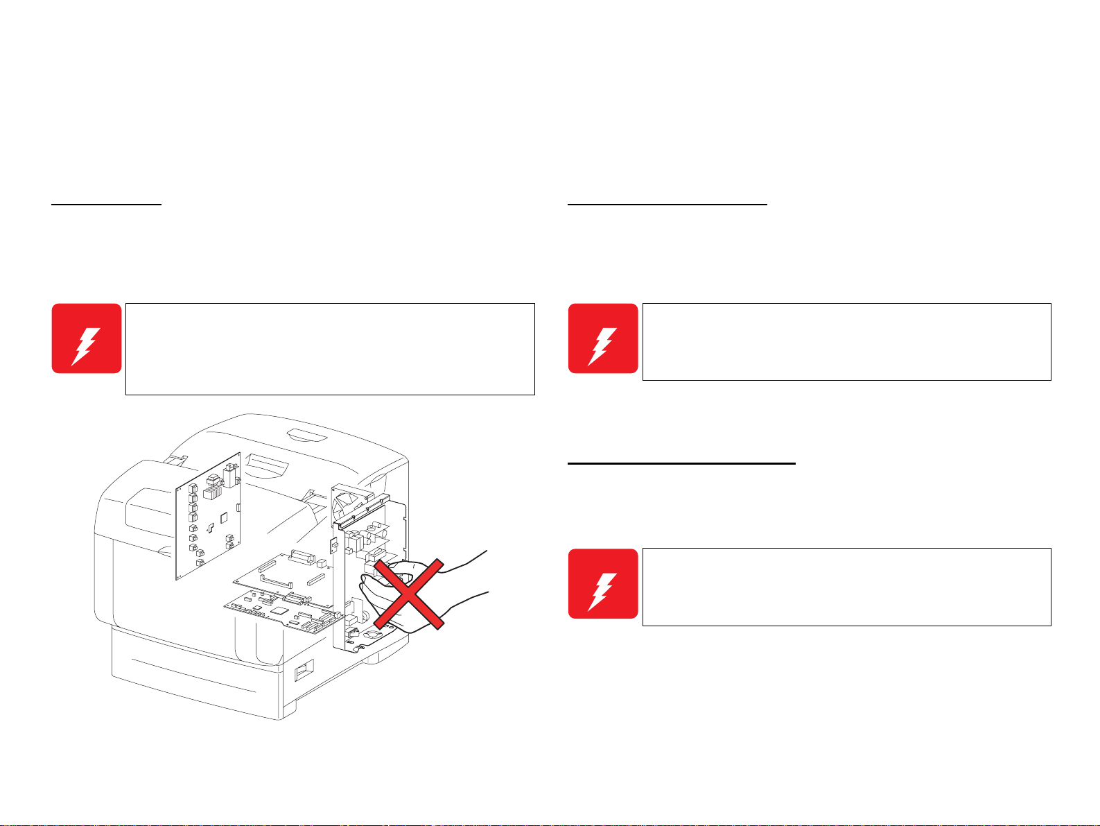
Power Supply
Before starting any service procedure, turn the printer power off and unpl u g the power
cord from the wall outlet.When the power supply cable must b e connected, b e aware of
the potential for electrical shock and do all tasks by following the procedures in this
manual.
W A R N I N G
Do not touch any live parts other than the required parts while
the printer is on.
As the LVPS ASSY (power supply section) is live even when the
power is off, never touch the live parts.
Do not touch any live parts unless instructed to do so.
Mechanical Components
When servicing any driving assembly (e.g., gears), first turn the power off and unplug
the power cord, and then manually rotate the assembly.
W A R N I N G
Do not touch the driving part (e.g., gears) while the as sembly
(printer) is operating.
High Temperature Assembly
When working with hot parts (FUSER etc.) make sure to turn the power off, unplug the
power cable, and leave the printer until it cools down sufficiently to work with to
prevent burn injury.
W A R N I N G
As the inside of the printer is high-temperature state immediately
after the operation, leave it more than 40 minutes before working.
Ida_00_002A
Page 8
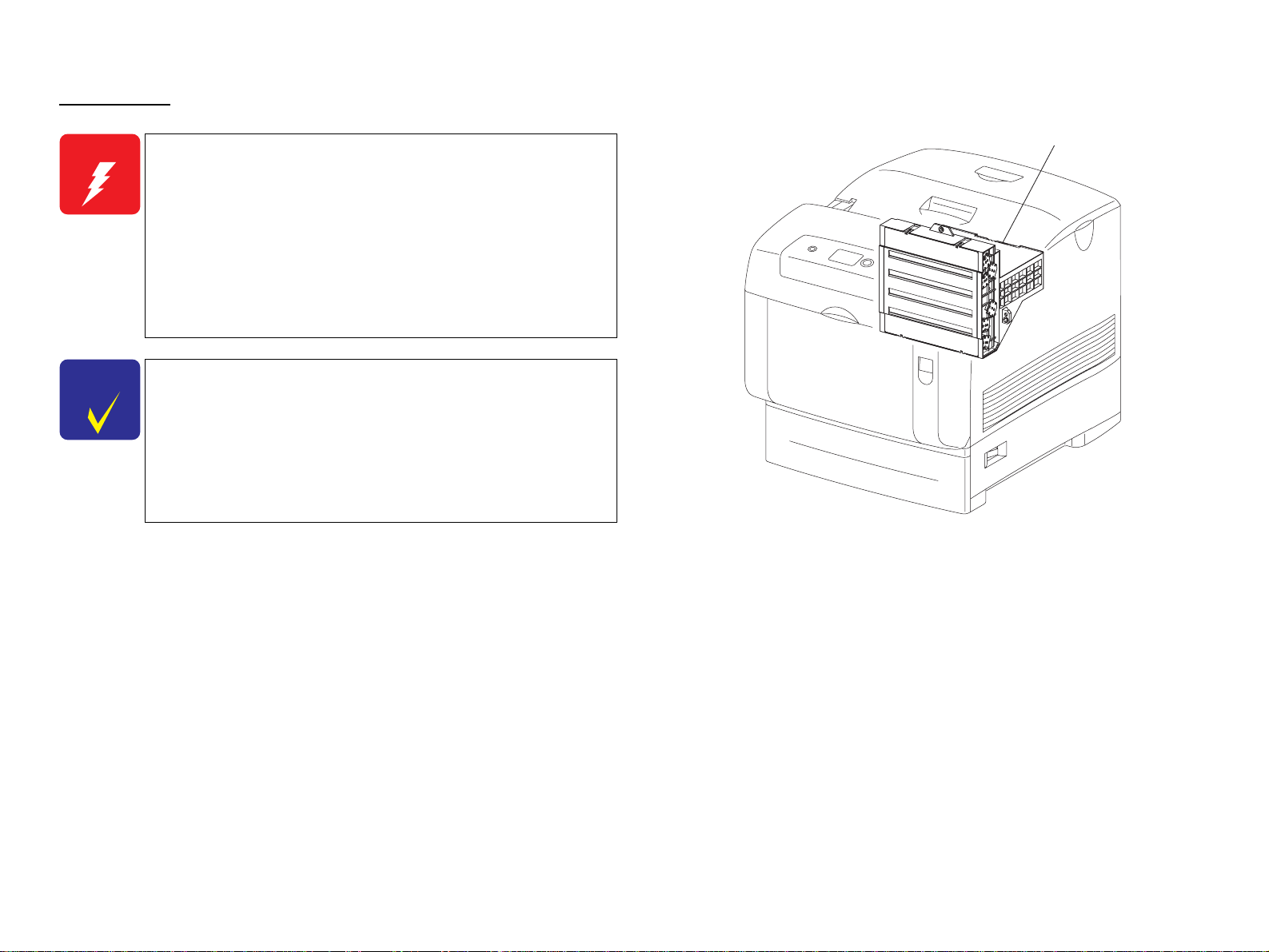
Laser Beam
W A R N I N G
C H E C K
P O I N T
Letting a laser beam get directly into your eyes could result in
loss of vision.
Never open the Cover where the Warning Label about Laser
Beam is affixed.
Before disassembling or assembling, be sure to turn the power
off.
If you need to work on the printer with power applied, strictly
follow the instructions in this manual.
Und erstand hazardous nature of the laser beam, use extreme
caution to avo i d i n jury of yoursel f and anyone around you.
Sin ce the laser beam has a narrower frequency band and more
coherent phases than any other light (sunlight, electric light),
the beam has excellent monochromaticity and convergence,
thus it reaches long distances.
Because of these characteristics, the laser beam converges into
one point, causing high density and high temperature, which is
harmful to the human body.
Reference: The laser beam in this printer is invisible.
ROS ASSY
Ida_00_003A
Page 9
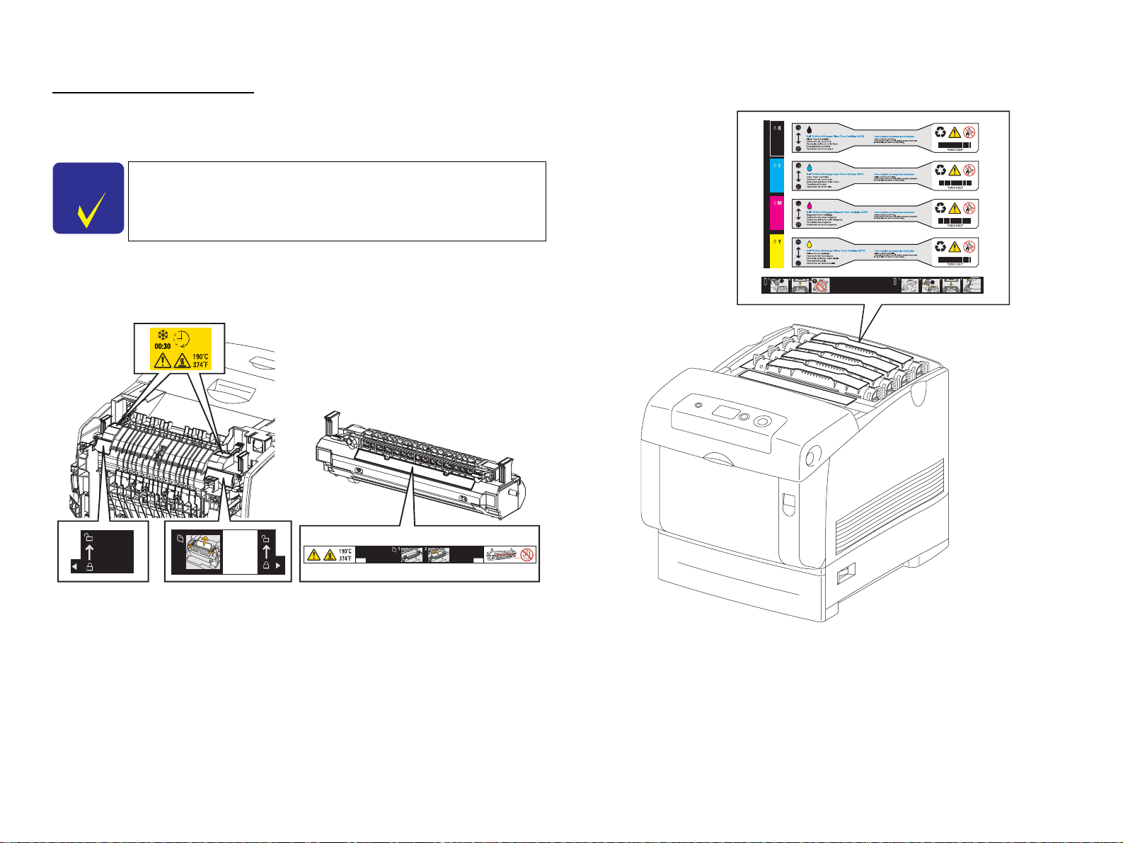
Warning/Caution Labels
Warning labels and caution labels are attached on the corresponding locations on or in
the printer.
Caution Label for Toner Cartridges
C H E C K
P O I N T
In maintenance work, check that the labels are free from peeling
and soiling.
Caution Label for High-temperature Surface
Ida_Sec00_010GA
Ida_00_004A
Page 10
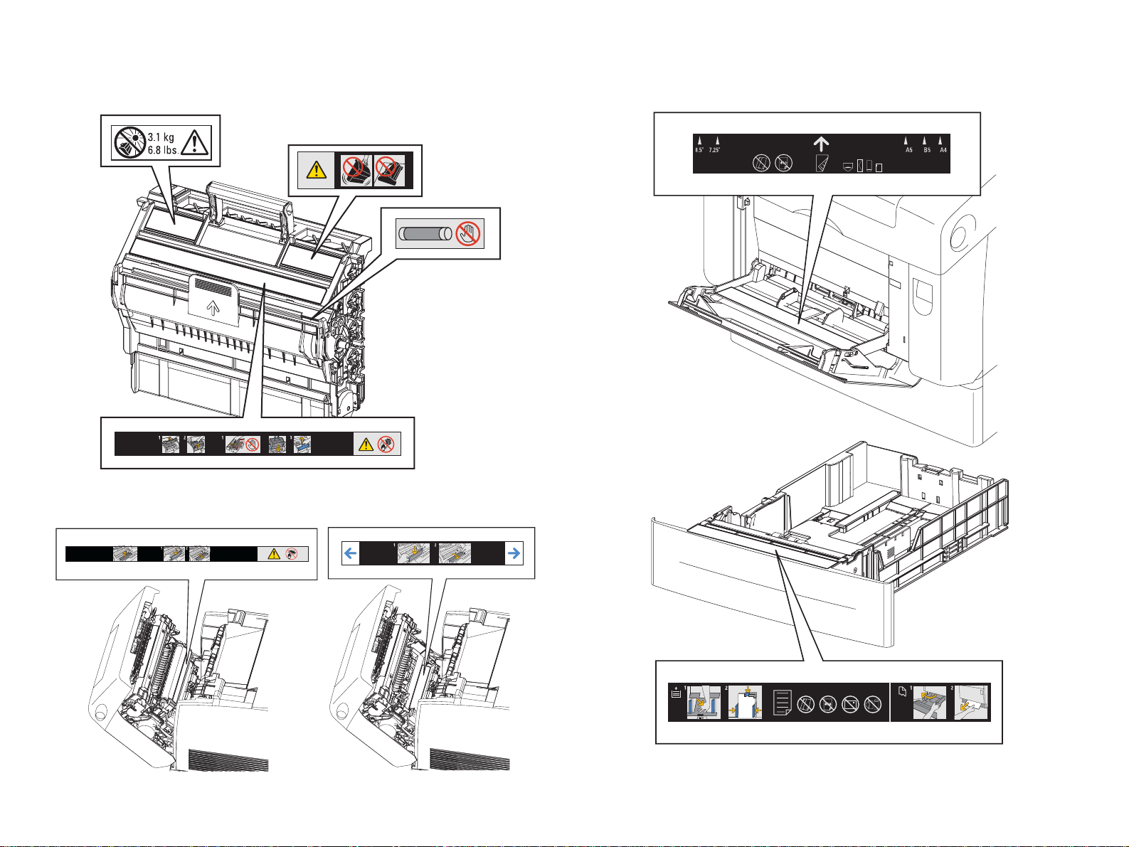
Caution Label about PHD ASSY and BTR ASSY Caution Label about MSI and Paper Tray
Ida_Sec00_005FA
Ida_00_009A
Ida_00_006A
Page 11
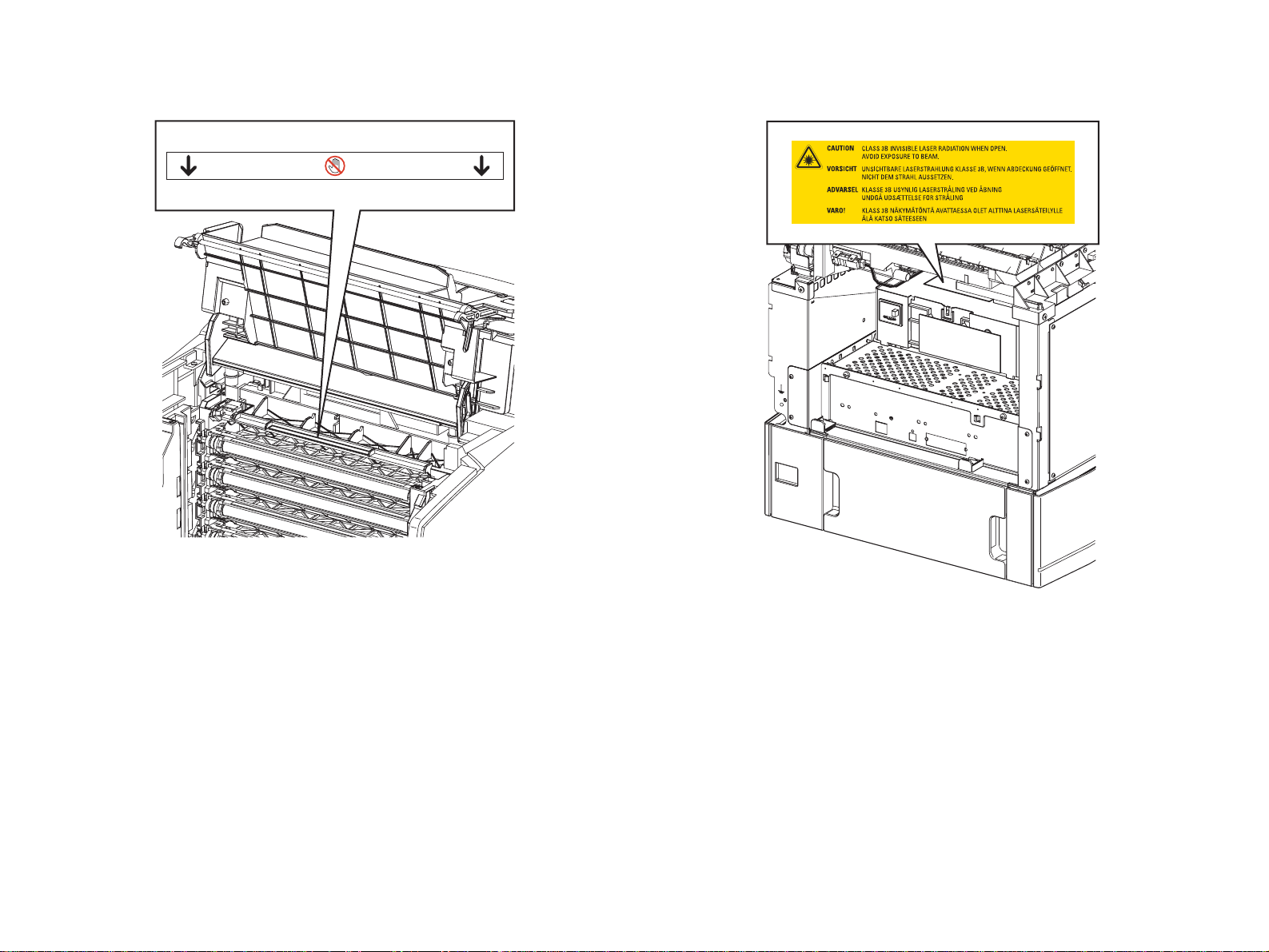
Caution Label about FRAME ASSY DEVE Caution Label about ROS ASSY
Ida_Sec00_007GA
Ida_Sec00_008GA
Page 12
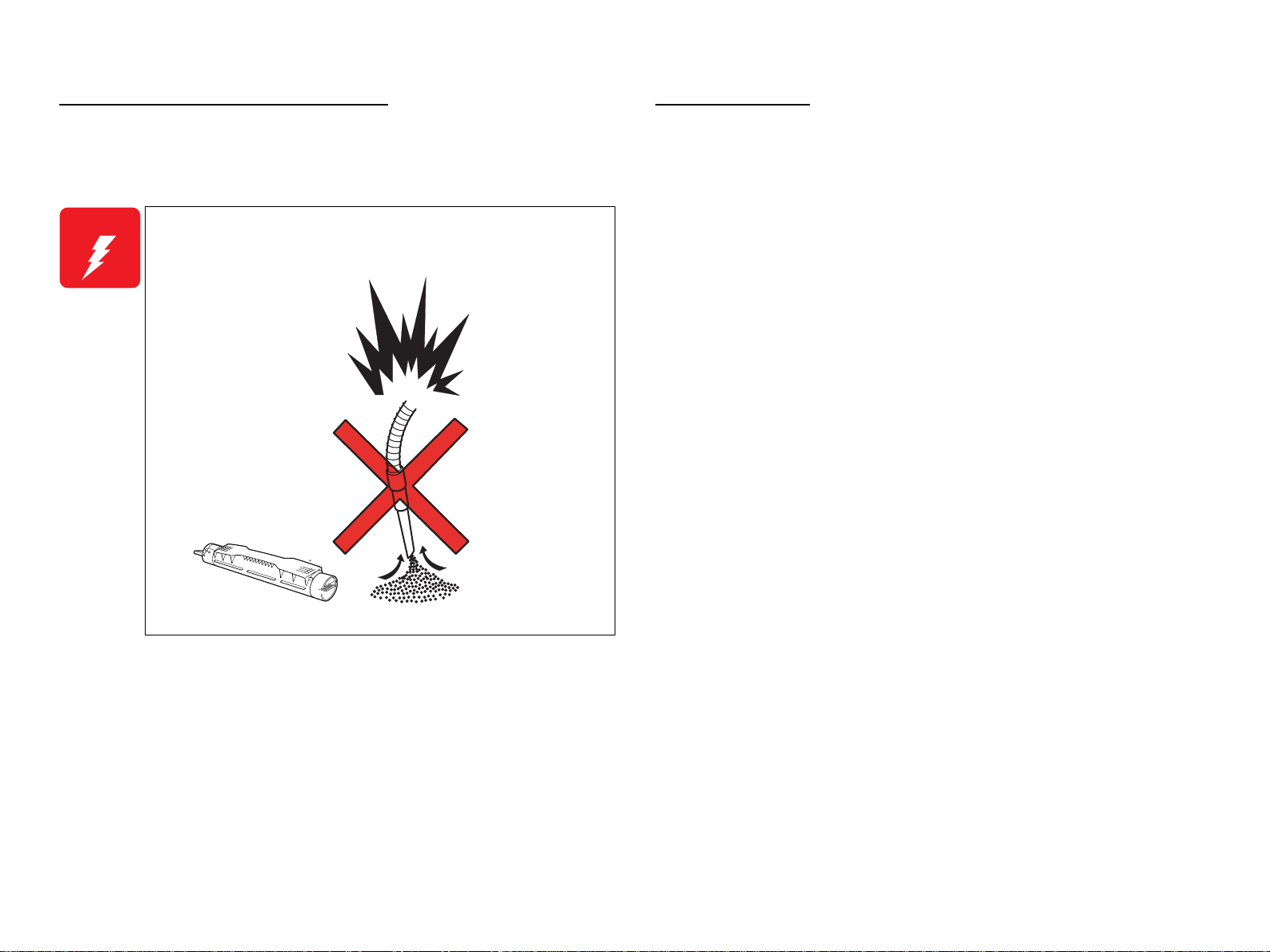
Cautions relating to Toner cleaning
Storage of Paper
To prevent ignition, explosion, burn, injury, etc., do not use a general vacuum
cleaner for cleaning dropped toner. (To do so may cause the toner to catch fire by
sparks in the vacuum cleaner.)
W A R N I N G
Do not pick up dropped toner with a general vacuum cleaner.
To do so may cause ignition .
Damp papers could cause printing quality troubles. To keep papers in their best
condition, store them wrapping tightly with packing material or putting them into a
plastic bag.
Leg_Sec001_014EA
Page 13

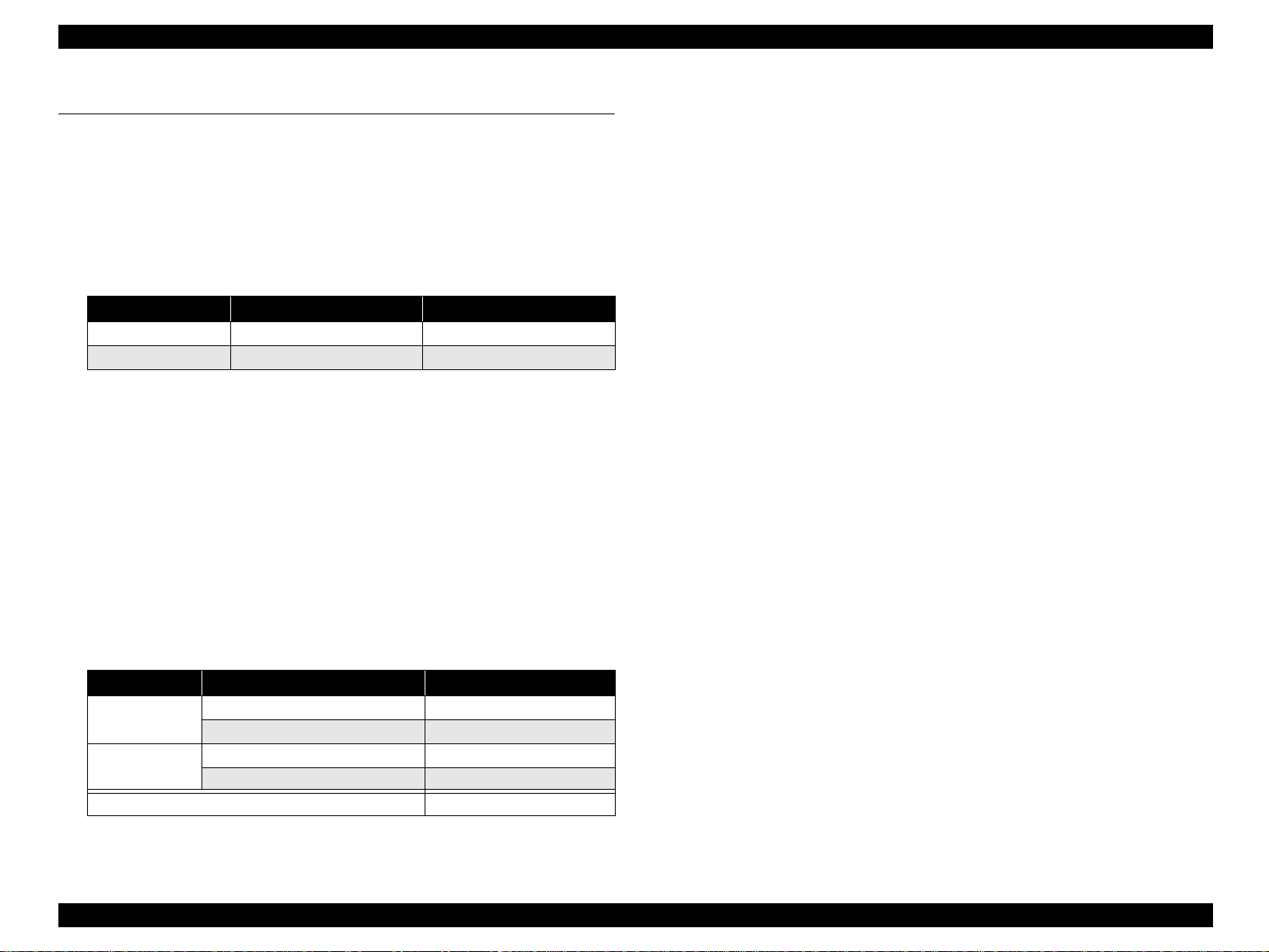
Revision Status
Revision Date of Issue Description
A
JUN 24, 2005
First release
Page 14

EPSON AcuLaser C4200 Revision A
Contents
Chapter 1 PRODUCT DESCRIPTION
1.1 Overview ............................................................................................................... 7
1.1.1 Engine Features ............................................................................................ 7
1.1.2 Controller Features....................................................................................... 7
1.1.3 Software Features ......................................................................................... 8
1.2 Basic Specifications.............................................................................................. 9
1.2.1 Process Specifications & System.................................................................. 9
1.2.2 Printer Basic Specifications .......................................................................... 9
1.3 Paper Specifications ............................................................................................ 19
1.3.1 Paper Type.................................................................................................. 19
1.3.2 Paper that may cause printing defects, paper jams or printer malfunction. 19
1.3.3 Available Paper by Feeder.......................................................................... 20
1.3.4 Printing Area............................................................................................... 20
1.4 Reliability and Serviceability.............................................................................. 21
1.4.1 Reliability ................................................................................................... 21
1.4.2 Durability.................................................................................................... 22
1.4.3 Serviceability.............................................................................................. 22
1.5 Service Conditions............................................................................................... 23
1.6 Conditions for Storage and Transport ................................................................. 24
1.7 Electrical Characteristics..................................................................................... 25
1.8 Compatible Specification .................................................................................... 26
1.9 Consumables/Periodic Replacement Unit........................................................... 27
1.9.1 Specifications.............................................................................................. 27
1.9.2 Conditions for Storage and Transport......................................................... 28
1.10 External Appearance and Unit Names.............................................................. 29
1.10.1 Unit Names............................................................................................... 29
1.11 Engine Restrictions............................................................................................ 31
1.11.1 Controls that Restrict Print Speed............................................................. 31
1.11.2 Controls that Restrict Print Start............................................................... 31
1.11.3 Toner Duty Limiting Value...................................................................... 31
1.12 Notes When Replacing Consumables and Installing Optional Products........... 32
1.12.1 Consumables............................................................................................. 32
1.12.2 Optional Products..................................................................................... 32
1.13 Life Details........................................................................................................ 33
1.14 Engine Control (Appendix)............................................................................... 34
1.15 Controller Specifications................................................................................... 36
1.15.1 Controller Basic Specifications................................................................ 36
1.15.2 Controller Configuration.......................................................................... 37
1.15.3 External Interface Specifications.............................................................. 37
1.16 Control Panel..................................................................................................... 40
1.16.1 External Appearance and Names.............................................................. 40
1.16.2 Panel Settings List.................................................................................... 42
1.16.3 Explanation of Menu and Settings............................................................ 53
1.16.4 Special Operations.................................................................................... 59
1.17 Printer Status..................................................................................................... 60
1.17.1 List of Printer Messages........................................................................... 60
1.17.2 Status Messages and Troubleshooting...................................................... 62
1.17.3 Warning Messages and Troubleshooting ................................................. 63
1.17.4 Error Messages and Troubleshooting...................................................... 65
1.17.5 Service Call Error Messages..................................................................... 68
1.18 Expanding the RAM.......................................................................................... 70
1.19 Handling Precautions ........................................................................................ 71
1.20 Status Sheet....................................................................................................... 72
1.21 Engine Status Sheet/Print Log Report............................................................... 76
1.22 Color Registration Sheet................................................................................... 77
1.23 Form Overlay List............................................................................................. 78
1.24 Paper Handling Algorithm................................................................................ 79
Chapter 2 OPERATING PRINCIPLES
2.1 Print Process........................................................................................................ 82
2.1.1 Print Process Overview .............................................................................. 82
2.1.2 Print Process Diagram................................................................................ 83
2.1.3 Technical Explanation of Print Process...................................................... 84
1
Page 15

EPSON AcuLaser C4200 Revision A
2.2 Flow of Print Data............................................................................................... 92
2.2.1 Data Flow.................................................................................................... 92
2.3 Drive Transmission Path ..................................................................................... 93
2.3.1 DRIVE ASSY MAIN................................................................................. 93
2.3.2 DRIVE ASSY DEVE................................................................................. 94
2.3.3 DISPENSER ASSY (Y, M, C, K).............................................................. 96
2.3.4 DRIVE ASSY FUSER ............................................................................... 97
2.3.5 MOTOR ASSY DUP 17PM....................................................................... 98
2.3.6 DRIVE ASSY (550-sheet Paper Cassette Unit)......................................... 99
2.3.7 DRIVE ASSY 2ND (1,100-sheet Paper Cassette Unit)........................... 100
2.4 Feeding Paper.................................................................................................... 101
2.4.1 Paper Feed Path (When options are not installed).................................... 101
2.4.2 Paper Feed Path (When the 550-sheet Paper Cassette is installed).......... 102
2.4.3 Paper Feed Path (When the 1100-sheet Paper Cassette is installed)........ 103
2.5 Main Structure and Function............................................................................. 104
2.5.1 Paper Cassette........................................................................................... 104
2.5.2 Paper Feeder ............................................................................................. 105
2.5.3 Optional Feeder (550-sheet Paper Cassette)............................................. 106
2.5.4 Optional Feeder (1100-sheet Paper Cassette)........................................... 108
2.5.5 Retard & Regi Assy.................................................................................. 110
2.5.6 Front Assy In............................................................................................ 111
2.5.7 Chute Assy Out......................................................................................... 112
2.5.8 BTR Assy & Fuser Assy........................................................................... 114
2.5.9 Xerographics............................................................................................. 116
2.5.10 Toner Cartridge....................................................................................... 117
2.5.11 Frame & Drive ........................................................................................ 119
2.5.12 Electrical................................................................................................. 120
2.6 Switch and Sensor............................................................................................. 122
2.7 Mode.................................................................................................................. 123
2.7.1 Printing Mode........................................................................................... 123
2.7.2 Operating Modes ...................................................................................... 123
2.8 Control............................................................................................................... 124
2.8.1 Paper Size Control.................................................................................... 124
2.8.2 Paper Feeder Selection Control................................................................ 124
2.8.3 ROS Light Intensity Control..................................................................... 124
2.8.4 Process Control......................................................................................... 125
2.8.5 Color Registration Control....................................................................... 128
2.8.6 BTR ASSY Control.................................................................................. 129
2.8.7 Toner Control............................................................................................ 130
2.8.8 Fuser Control............................................................................................ 131
2.9 Detection Mechanisms..................................... ...... ........................................ ... 132
2.10 Features of the Controller................................................................................ 134
2.10.1 Power Supply.......................................................................................... 136
Chapter 3 TROUBLESHOOTING
3.1 Procedure for Troubleshooting.......................................................................... 138
3.1.1 Procedure for Troubleshooting................................................................. 138
3.1.2 Preliminary Check.................................................................................... 138
3.1.3 Precautions in Performing Troubleshooting Work................................... 139
3.1.4 Notes on Using FIP................................................................................... 140
3.2 Paper Jam .......................................................................................................... 141
3.2.1 Paper Transferring Path and The Main Components ............................... 142
3.2.2 Paper Jam Handling (FIP)........................................................................ 144
3.2.3 Check Points for Frequent Paper Jam....................................................... 151
3.3 Level 1 FIP........................................................................................................ 152
3.3.1 Level 1 FIP............................................................................................... 152
3.3.2 The flow of Level 1 FIP........................................................................... 152
3.4 Level 2 FIP........................................................................................................ 153
3.4.1 List of Warnings and Errors ..................................................................... 153
3.4.2 List of Service Request............................................................................. 158
3.4.3 Engine-related Trouble FIP...................................................................... 163
3.4.4 Controller-related Trouble FIP................................................................. 209
3.4.5 Print Quality Trouble FIP......................................................................... 211
3.4.6 Other FIP.................................................................................................. 225
3.5 Abnormal Noise-related Trouble............................ ...... ..... ................................ 228
3.5.1 Abnormal Noise-related Troubleshooting Entry Chart............................ 228
3.5.2 Abnormal Noise-related FIP..................................................................... 229
3.6 Test Print........................................................................................................... 233
Chapter 4 DISASSEMBLY/REASSEMBLY
4.1 Overview.............................. ...... ...... ................................................................. 236
4.1.1 Precautions................................................................................................ 236
4.1.2 Before starting work................................................................................. 238
4.1.3 Screws....................................................................................................... 239
4.1.4 Tools......................................................................................................... 240
4.1.5 Conventions used in descriptions of procedures...................................... 241
2
Page 16

EPSON AcuLaser C4200 Revision A
4.2 COVERS ........................................................................................................... 242
4.2.1 COVER TOP MAIN................................................................................. 242
4.2.2 CONSOLE PANEL.................................................................................. 243
4.2.3 COVER ASSY FRONT HEAD ............................................................... 244
4.2.4 COVER ASSY TOP PHD........................................................................ 245
4.2.5 COVER REAR ASSY.............................................................................. 246
4.2.6 FAN REAR............................................................................................... 247
4.2.7 COVER SIDE R ASSY............................................................................ 248
4.2.8 COVER FRONT R................................................................................... 249
4.2.9 TRAY ASSY MSI BASE............................................................. ..... ...... . 250
4.2.10 COVER ASSY MSI ............................................................................... 251
4.2.11 COVER FRONT L ASSY...................................................................... 252
4.2.12 COVER SIDE L ASSY.......................................................................... 253
4.2.13 COVER ASSY TOP, COVER TOP STOPPER..................................... 254
4.3 PAPER CASSETTE.......................................................................................... 255
4.3.1 ROLL ASSY RETARD............................................................................ 255
4.3.2 HOLDER ASSY RETARD...................................................................... 256
4.3.3 KIT GUIDE SIDE L, KIT GUIDE SIDE R............................................. 257
4.3.4 KIT GUIDE END..................................................................................... 259
4.4 PAPER FEEDER............................................................................................... 261
4.4.1 CHUTE ASSY FEEDER.......................................................................... 261
4.4.2 COVER CST ............................................................................................ 262
4.4.3 FEEDER ASSY (REFERENCE ONLY) ................................................. 263
4.4.4 SWITCH ASSY SIZE .............................................................................. 266
4.4.5 SWITCH................................................................................................... 267
4.4.6 HARNESS ASSY OPFPLG..................................................................... 268
4.4.7 PICK UP ASSY........................................................................................ 269
4.4.8 ROLL ASSY TURN, BEARING SLEEVE, PLASTIC ........................... 270
4.4.9 SENSOR NO PAPER.............................................................................. . 271
4.4.10 SENSOR LOW PAPER ......................................................................... 272
4.4.11 SOLENOID FEED ................................................................................. 273
4.4.12 ACTUATOR LOW PAPER................................................................... 274
4.4.13 CHUTE UPPER (REFERENCE ONLY)............................................... 275
4.4.14 ROLL ASSY FEED................................................................................ 276
4.4.15 ACTUATOR NO PAPER ...................................................................... 277
4.5 RETARD & REGI ASSY ................................................................................. 278
4.5.1 ACTUATOR REGI.................................................................................. 278
4.5.2 SENSOR REGI......................................................................................... 279
4.5.3 CHUTE ASSY REGI IN.......................................................................... 280
4.5.4 SENSOR OHP.......................................................................................... 281
4.5.5 ROLL ASSY RETARD............................................................................ 282
4.5.6 CHUTE ASSY REGI............................................................................... 283
4.5.7 ROLL REGI METAL............................................................................... 284
4.5.8 ROLL REGI RUBBER ............................................................................ 285
4.5.9 CLUTCH REGI........................................................................................ 286
4.5.10 CLUTCH TURN.................................................................................... 287
4.5.11 ROLL TURN MSI.................................................................................. 288
4.6 CHUTE ASSY IN & OUT................................................................................ 289
4.6.1 FUSER ASSY........................................................................................... 289
4.6.2 BTR ASSY............................................................................................... 290
4.6.3 HOLDER ASSY CTD.............................................................................. 291
4.6.4 SENSOR TNR FULL............................................................................... 292
4.6.5 DRIVE ASSY FUSER............................................................................. 294
4.6.6 SOLENOID FEED MSI........................................................................... 296
4.6.7 SENSOR NO PAPER............................................................................... 299
4.6.8 ACTUATOR NO PAPER MSI................................................................ 300
4.6.9 ROLL ASSY FEED.................................................................................. 302
4.6.10 SENSOR FULL STACK........................................................................ 304
4.6.11 SENSOR DUP JAM............................................................................... 305
4.6.12 ACTUATOR FULL STACK................................................................. 307
4.6.13 MOTOR ASSY DUP 17PM................................................................... 308
4.6.14 ACTUATOR DUP ................................................................................. 309
4.6.15 ROLL DUP............................................................................................. 310
4.6.16 ROLL EXIT............................................................................................ 311
4.6.17 CHUTE ASSY DUP IN ......................................................................... 312
4.6.18 CHUTE ASSY DUP OUT ..................................................................... 315
4.6.19 FAN FRONT.......................................................................................... 319
4.7 XEROGRAPHICS ................................................. ...... ..... ................................ 320
4.7.1 ROS ASSY............................................................................................... 320
4.7.2 HSG ASSY BIAS..................................................................................... 321
4.8 DEVELOPMENT ................................. ...... ...................................................... 322
4.8.1 FRAME ASSY DEVE.............................................................................. 322
4.8.2 CONN_ASSY_CRUM_MC..................................................................... 324
4.8.3 DEVE ASSY (Y), (M), (C), (K)............................................................... 325
4.8.4 DISPENSER ASSY-4 (REFERENCE ONLY)........................................ 326
4.8.5 DISPENSER ASSY (Y)........................................................................... 329
4.8.6 DISPENSER ASSY (M) .......................................................................... 331
4.8.7 DISPENSER ASSY (C) ........................................................................... 333
4.8.8 DISPENSER ASSY (K)........................................................................... 335
4.8.9 SENSOR NO TNR (Y), (M), (C)............................................................. 337
3
Page 17

EPSON AcuLaser C4200 Revision A
4.8.10 SENSOR NO TNR (K)........................................................................... 338
4.8.11 ACTUATOR SENSOR 2....................................................................... 339
4.8.12 BOX ASSY CRUM READER............................................................... 340
4.9 DRIVE............................................................................................................... 342
4.9.1 DRIVE ASSY DEVE............................................................................... 342
4.9.2 DRIVE ASSY MAIN............................................................................... 344
4.10 ELECTRICAL................................................................................................. 345
4.10.1 LVPS ASSY (REFERENCE ONLY)..................................................... 345
4.10.2 LVPS....................................................................................................... 347
4.10.3 HARNESS ASSY AC INLET................................................................ 348
4.10.4 HARNESS ASSY INTERLOCK........................................................... 349
4.10.5 PWBA EEPROM.................................................................................... 350
4.10.6 PWBA MCU IDTN................................................................................ 351
4.10.7 SENSOR HUM....................................................................................... 355
4.10.8 HVPS...................................................................................................... 356
4.10.9 ESS BOX (REFERENCE ONLY) ......................................................... 356
4.10.10 PWBA ESS MAIN............................................................................... 358
4.10.11 PWBA ESS ROM................................................................................. 360
4.10.12 PWBA NIC C533................................................................................. 361
4.11 ONE TRAY OPTION FEEDER..................................................................... 362
4.11.1 1 TRAY OPTION FEEDER ASSY ....................................................... 362
4.11.2 HARNESS ASSY OPFREC................................................................... 363
4.11.3 PWBA OPTFDR 1T............................................................................... 365
4.11.4 COVER RIGHT...................................................................................... 366
4.11.5 HARNESS ASSY OPFPLG2................................................................. 367
4.11.6 CHUTE ASSY FEEDER........................................................................ 369
4.11.7 COVER LEFT........................................................................................ 370
4.11.8 SWITCH ASSY SIZE............................................................................ 371
4.11.9 PICK UP ASSY...................................................................................... 373
4.11.10 ROLL ASSY TURN............................................................................. 376
4.11.11 CLUTCH ELECTRO MAGNETIC..................................................... 377
4.11.12 SENSOR NO PAPER........................................................................... 378
4.11.13 SENSOR LOW PAPER ....................................................................... 379
4.11.14 SOLENOID FEED ............................................................................... 381
4.11.15 DRIVE ASSY....................................................................................... 382
4.11.16 ACTUATOR LOW PAPER................................................................. 383
4.11.17 CHUTE UPPER (REFERENCE ONLY)............................................. 384
4.11.18 ROLL ASSY FEED.............................................................................. 385
4.11.19 ACTUATOR NO PAPER .................................................................... 386
4.11.20 ROLL ASSY RETARD........................................................................ 387
4.11.21 HOLDER ASSY RETARD.................................................................. 388
4.11.22 KIT GUIDE SIDE L, KIT GUIDE SIDE R......................................... 389
4.11.23 KIT GUIDE END................................................................................. 391
4.12 TWO TRAY OPTION FEEDER.................................................................... 393
4.12.1 2 TRAY OPTION FEEDER ASSY....................................................... 393
4.12.2 COVER ASSY LEFT............................................................................. 394
4.12.3 COVER ASSY RIGHT.......................................................................... 395
4.12.4 COVER ASSY FRONT......................................................................... 396
4.12.5 COVER CST.......................................................................................... 397
4.12.6 FEEDER ASSY LEFT........................................................................... 398
4.12.7 FEEDER ASSY RIGHT......................................................................... 399
4.12.8 SWITCH ASSY SIZE............................................................................ 400
4.12.9 CHUTE ASSY FEEDER........................................................................ 401
4.12.10 HARNESS ASSY OPFREC2............................................................... 402
4.12.11 PWBA OPTFDR 2T............................................................................. 403
4.12.12 DRIVE ASSY 2ND.............................................................................. 404
4.12.13 PICK UP ASSY 3RD........................................................................... 405
4.12.14 ROLL ASSY TURN............................................................................. 408
4.12.15 CLUTCH ASSY................................................................................... 409
4.12.16 SENSOR NO PAPER........................................................................... 410
4.12.17 SENSOR LOW PAPER....................................................................... 411
4.12.18 SOLENOID FEED............................................................................... 412
4.12.19 ACTUATOR LOW PAPER....................................... ...... .................... 413
4.12.20 CHUTE UPPER (REFERENCE ONLY)............................................. 414
4.12.21 ROLL ASSY FEED.............................................................................. 415
4.12.22 ACTUATOR NO PAPER.................................................................... 416
4.12.23 PICK UP ASSY 4TH ........................................................................... 418
4.12.24 ROLL ASSY TURN............................................................................. 421
4.12.25 CLUTCH ELECTRO MAGNETIC..................................................... 422
4.12.26 SENSOR NO PAPER........................................................................... 423
4.12.27 SENSOR LOW PAPER....................................................................... 424
4.12.28 SOLENOID FEED............................................................................... 425
4.12.29 ACTUATOR LOW PAPER....................................... ...... .................... 426
4.12.30 CHUTE UPPER (REFERENCE ONLY)............................................. 427
4.12.31 ROLL ASSY FEED.............................................................................. 428
4.12.32 ACTUATOR NO PAPER.................................................................... 429
4.12.33 ROLL ASSY RETARD........................................................................ 431
4.12.34 HOLDER ASSY RETARD.................................................................. 432
4.12.35 KIT GUIDE SIDE L, KIT GUIDE SIDE R......................................... 433
4.12.36 KIT GUIDE END................................................................................. 435
4
Page 18

EPSON AcuLaser C4200 Revision A
4.12.37 FOOT ASSY A, FOOT ASSY B ......................................................... 437
Chapter 5 ADJUSTMENT
5.1 Overview ........................................................................................................... 439
5.1.1 Precautions................................................................................................ 439
5.1.2 Adjustment Execution Timing.................................................................. 440
5.2 Adjustment/Action ............................................................................................ 441
5.2.1 Adjusting Color Registration Alignment.................................................. 441
5.2.2 Writing USB ID........................................................................................ 442
5.2.3 Firmware Update...................................................................................... 444
Chapter 6 MAINTENANCE
6.1 Overview ........................................................................................................... 452
6.2 Cleaning............................................................................................................. 454
6.3 Maintenance Menu............................................................................................ 458
6.3.1 Entry into Maintenance Mode.................................................................. 458
6.3.2 Maintenance Menu Items ......................................................................... 459
6.4 Sheet for Servicing............................................................................................ 460
6.4.1 Engine Status Sheet.................................................................................. 460
6.4.2 Print Log Report....................................................................................... 464
6.5 Consumables and Components That Need Periodic Replacement.................... 466
6.5.1 Consumables............................................................................................. 466
6.5.2 Regular Replacement Parts....................................................................... 468
7.7 Circuit Diagram................................................................................................. 551
Chapter 7 APPENDIX
7.1 Connectors......................................................................................................... 471
7.1.1 The List of Plugs and Jacks...................................................................... 471
7.1.2 P/J Layout Diagram.................................................................................. 474
7.2 Wire Net ............................................................................................................ 479
7.3 Wiring Connection Diagrams.................................................... ...... .................. 482
7.3.1 Marks used in the Diagram....................................................................... 482
7.4 Wiring Connection Diagram between Parts...................................................... 485
7.4.1 Configurations.......................................................................................... 485
7.4.2 Marks used in the Wiring Connection Diagram between Parts................ 488
7.5 Service Parts List ............................................................................................... 516
7.6 Exploded diagram.............................................................................................. 520
5
Page 19

PRODUCT DESCRIPTION
CHAPTER
1
Page 20
EPSON AcuLaser C4200 Revision A
1.1 Overview
This printer is a non-impact color page printer that takes advantage of a laser and
electrophotographic technologies. It provides 1200/600 dpi of resolution, and the
printing speed is 25 pages per minute (ppm) for color single-side printing, or 35 ppm
for monochrome single-side printing.
1.1.1 Engine Features
High-speed A4 tandem engine
Color Monochrome
Simplex printing 25.0 ppm 35.0 ppm
Duplex printing 14.8 ppm 20.4 ppm
Note : When printing on A4-si ze d pape r
Duplex print unit equipped as standard
(Duplex pri nting is not available on extra thic k paper, OHP sheet (transparency),
labels, and envelopes.)
Compatibl e with hig h qual ity plain paper that enables higher quality printing
Printable on thick paper and transparency for laser printer
This product is designed so that users can replace all the consumables.
• Toner cartridges (C, M, Y and K)
• Photoconductor Unit
• Transfer Unit
•Fuser Unit
High-capacity paper supply
Paper Feeder Capacity
Standard
Option
550-sheet paper cassette unit up to 550 sheets
1,100-sheet paper cassette unit up to 1100 shee ts
Maximum 2,350 sheets with 5 bins
MP tray up to 150 sheets
Lower cassette up to 550 sheets
1.1.2 Controller Features
High-speed controller for latest tandem
64-bit RISC CPU: Power PC 750FX 600 MHz
64-bit high-speed memory:DDR333 200 pin SO DIMM
(compatible with the RAM for AcuLaser C9100)
Standard RAM: 128MB
By installing additional RAM, the memory can be expanded up to 640MB
(128MB + 512MB). (The extended RAM must be installed to slot-1.
Changing the initial state of slot-0 is prohibited.)
Enhanced ASIC (FMV-FAIO)
The color management technologies are incorp orated into the hardware to achieve
high-speed processing.
Three Built-in interfaces
Parallel interface (IEEE 1284 compliant, Supports ECP)
USB interface (Rev. 2.0 HS)
Ethernet interface (100 Base-TX/10 Base-T)
Functions described below can be enhanced and increased in speed by expanding
memory with RAM DIMMs
CPGI drawing area
Image creating speed
Resolution
Receive buffer
Print buffer for collate printing
Updating firmware is available (RCC compatible) when a Flash ROM DIMM is
installed
Large capacity HDD such as 40GB can be installed
Paper eject capacity is 250 sheets, face-down only
PRODUCT DESCRIPTION Overview 7
Page 21

EPSON AcuLaser C4200 Revision A
1.1.3 Software Features
Color technologies
Smooth expanding of color images by ESC/Page-Color
Color/Monochrome auto-detect function
Supports 1200 dpi
Monitors printer status and printer environment by bi-directional EJL and MIB
Adobe PostScript3 is equipped as standard
Supports PCL5c with optional DIMM (1200 dpi not supported)
Engine controller ROM (only for Flash) can be upgraded
Panel display
Supports the new wide panel
Displays remaining amount of C, M, Y, and K toner on the panel
Displays toner cartridge p rese nce, paper size, and remaining amou nt o f papers
Help function
Supports 14 languages: English, French, Italian, German, Spanish,
Portuguese, Dutch, Swedish, Danish, Finnish, Norse, Chinese Simplified,
Chinese Traditional, and Korean
Suppo rts EPSON Status Monitor 3
Employs new user interface suitable for business use
PRODUCT DESCRIPTION Overview 8
Page 22
EPSON AcuLaser C4200 Revision A
1.2 Basic Specifications
1.2.1 Process Specifications & System
Printing method: Semiconductor laser beam scan and electro photography
with dry double component non-electromagnetic toner
Light source: Semiconductor laser
Photoconductor: Negative organic photoconductor
Charging: Roller charger
Development: Exposed area development
Toner: Chemical toner
Primary transfer: Roller transfer method
Fixing: Heated roller method and flexible belt nip method
1.2.2 Printer Basic Specifications
RESOLUTION
600 dpi, 1200 dpi
WARMING UP TIME
35 seconds or less: From turning the power on to ready-to-print status.
(at: 22°C, 55% RH, rated voltage, memory standard)
25 seconds or less: From standby mode to ready-to-print status.
(at 22°C, 55% RH, rated voltage, memory standard)
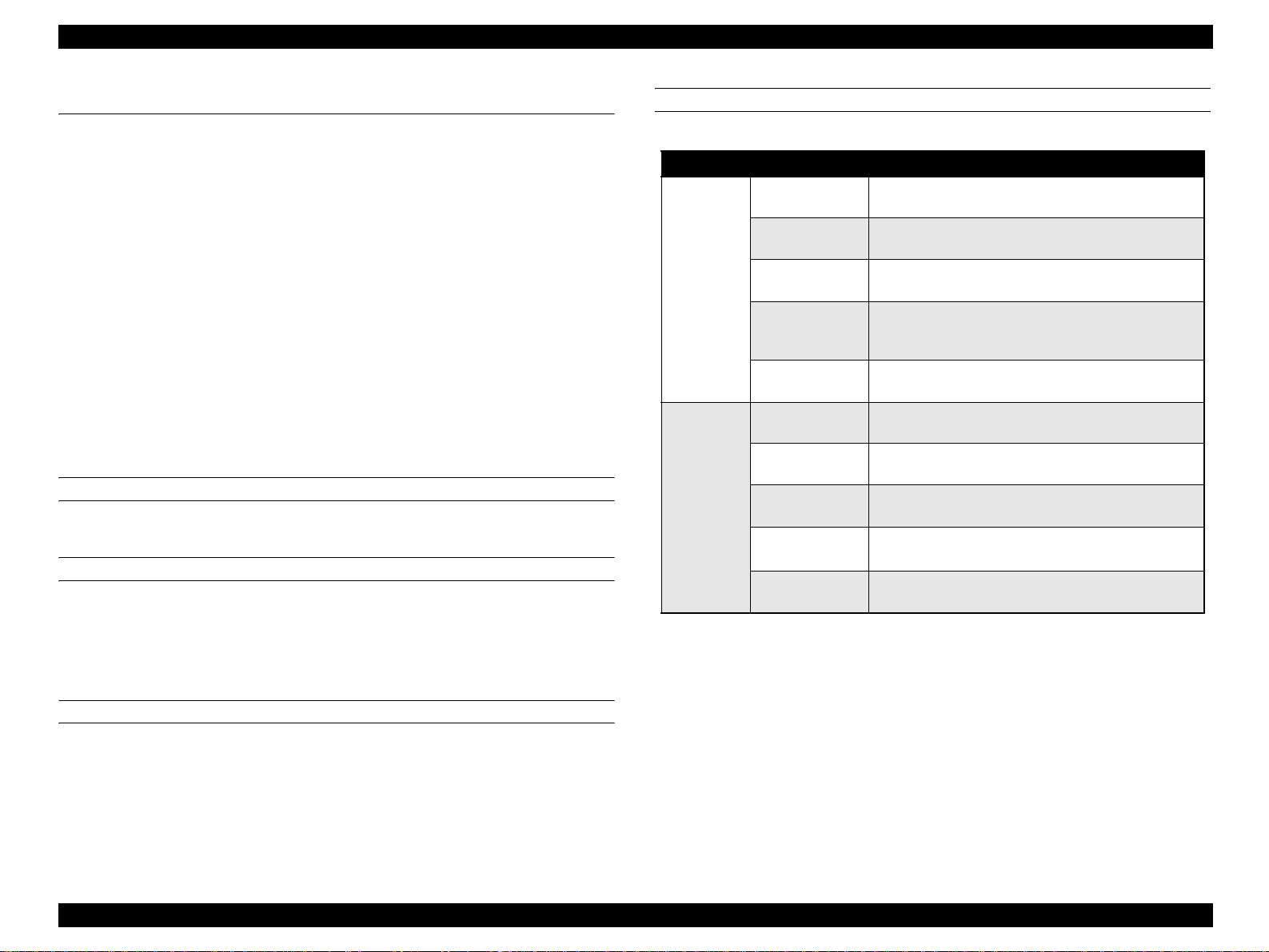
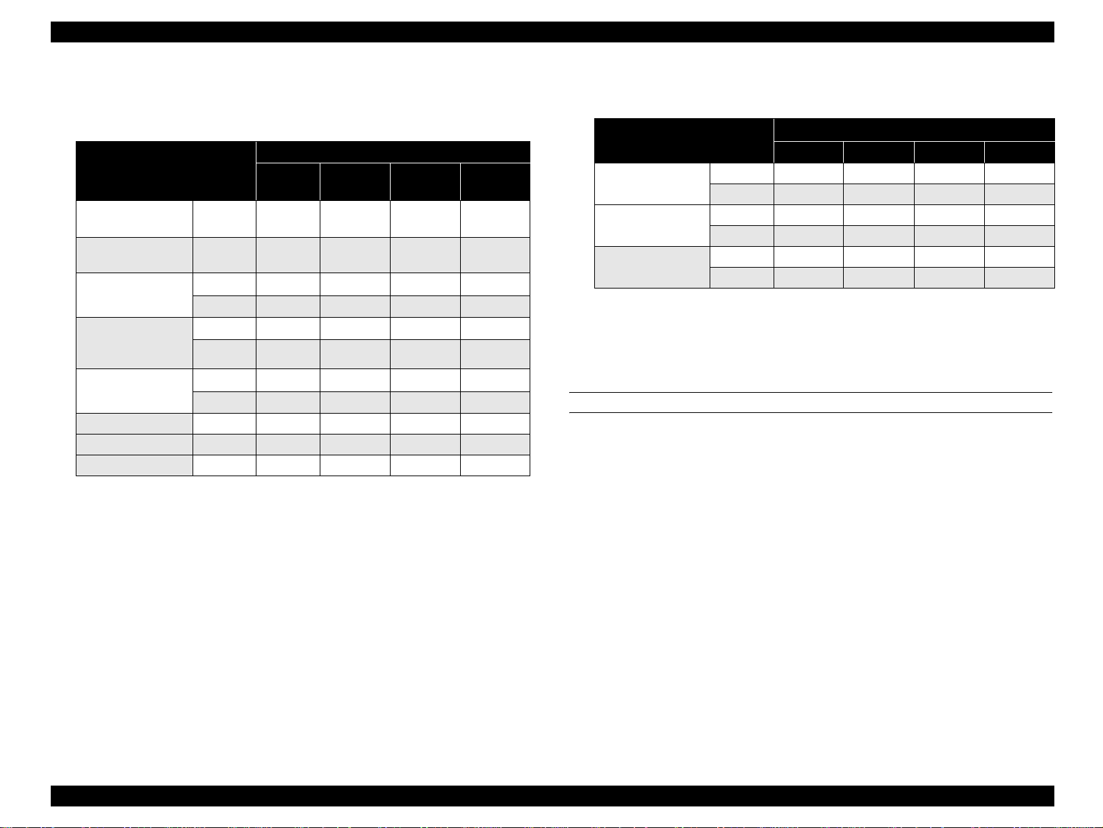
PRINTING SPEED MODE
Table 1-1. Printing Speed Mode
Standard 1
Low speed 1
Monochrome
mode (B/W)
Color mode
(F/C)
Note *: 164-216 g/m
Low speed 1
Low speed 2
Low speed 3
Standard 2
Low speed 1
Low speed 1
Low speed 2
Low speed 3
2
Printing Speed Mode
The resolution is set to 600 dpi.
Suitable for plain paper.
The resolution is set to 600 dpi.
Suitable for plain paper, thick paper, an d envelopes.
The resolution is set to 1200 dpi.
Suitable for plain paper, thick paper, an d envelopes.
The resolution is set to 600 dpi.
Suitable for plai n paper, thick paper , extra thick paper
and labels.
The resolution is set to 600 dpi.
Suitable for plain paper (high gross), and tr ansparency.
The resolution is set to 600 dpi.
Suitable for plain paper
The resolution is set to 600 dpi.
Suitable for plain paper, thick paper, an d envelopes.
The resolution is set to 1200 dpi.
Suitable for plain paper, thick paper, an d envelopes.
The resolution is set to 600 dpi.
Suitable for plain paper, extra thick paper*, and labels.
The resolution is set to 600 dpi.
Suitable for plain paper (high gross), and tr ansparency.
*
,
PRINT MODE
Color mode: Use four toners (CMYK) to print in full color.
Monochrome mode: Use only black toner (K) and the highest print speed is
available.
PRODUCT DESCRIPTION Basic Specifications 9
Page 23
EPSON AcuLaser C4200 Revision A
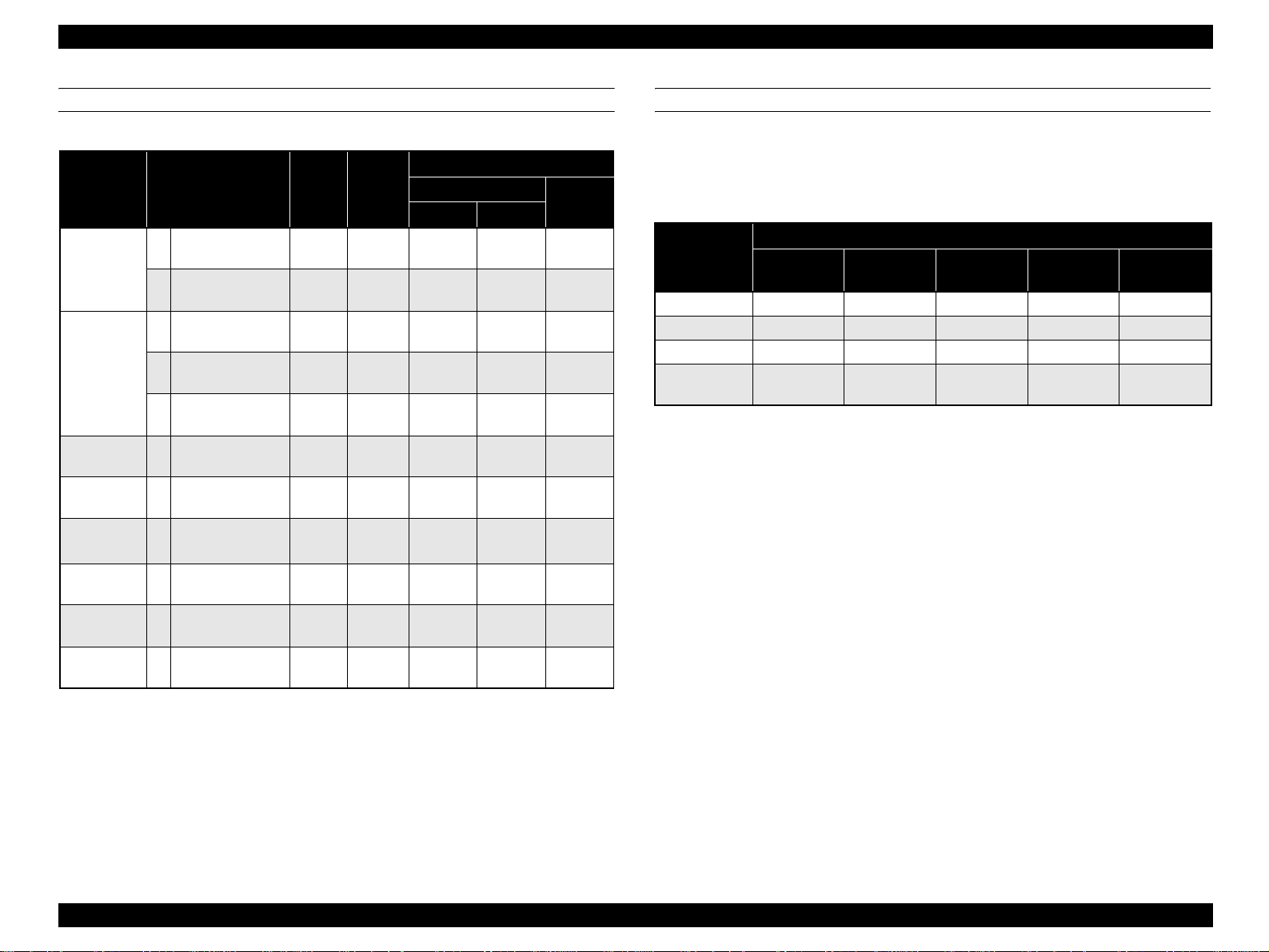
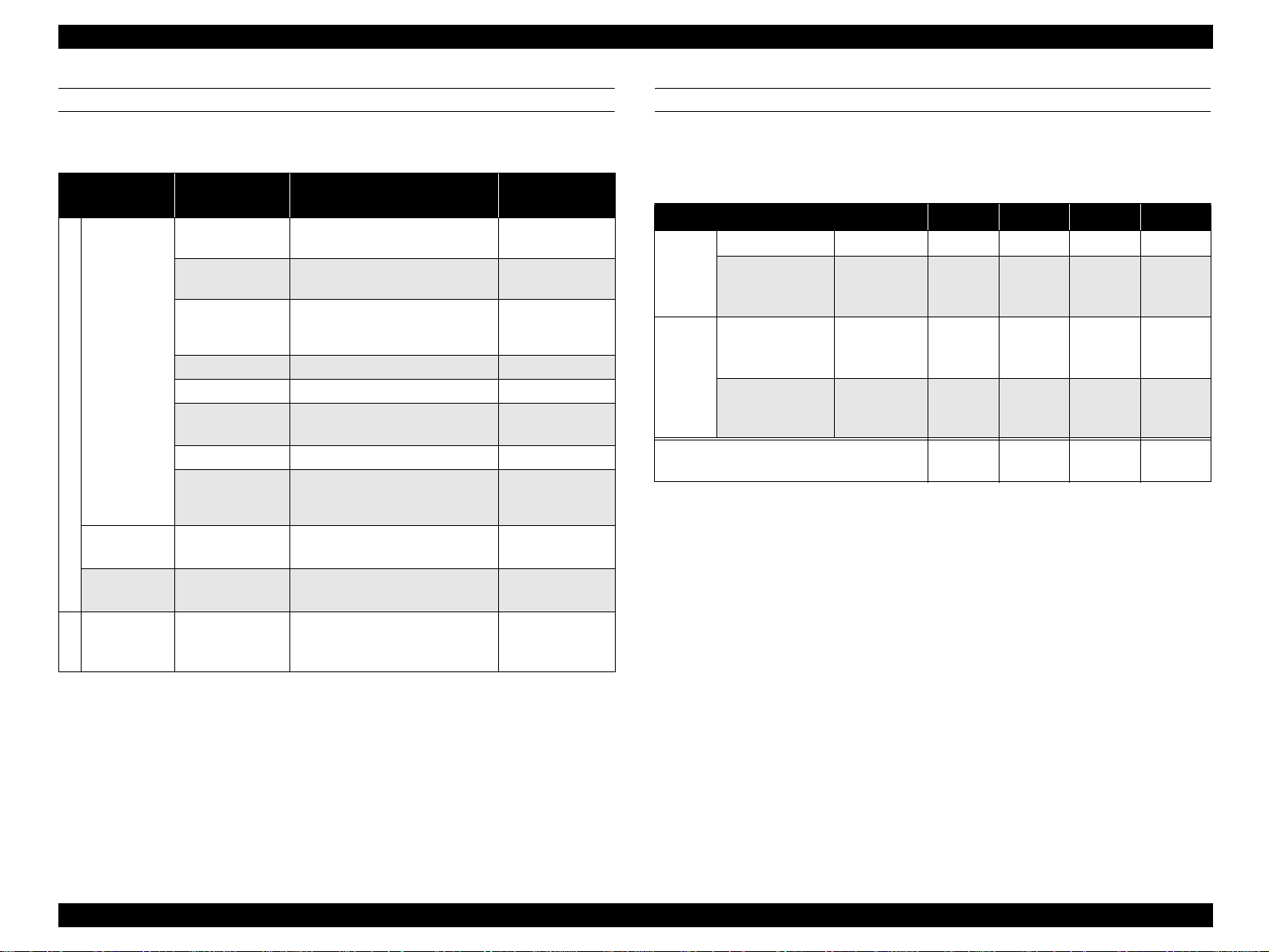
PRINTING MODE BY PAPER TYPE
Table 1-2. Printing Mode by Paper Type
1
Paper Type <Video I/F Name> Gross*
(1) <Plain paper-L> N
Normal
(2) <Plain paper-H> N
(3) <Plain paper-L> H
Normal-HQ
(4) <Plain paper-L> SH
<Plain (PPM-
(5)
Down)>
SH
Thick – <Heavier paper-L> H
Extra Thick – <Heavier paper-H> SH
Extra Thick
Back
Transparency –
<Heavier paper-H>
–
Back Face
<Transparency
(PPM-Down)>
SH
SH –
Envelope – <Envelope> H –
Label – <Label-H> SH –
Note *1: Gross
N: Normal Gross
H: High Gross
SH:Super High Gross
Paper
Weight
105g/m
105g/m
105g/m
105g/m
105g/m
106 to
163g/m
164 to
216g/m
164 to
216g/m
Basic
60 to
60 to
60 to
60 to
60 to
Printing Speed Mode
600 dpi
B/W FC
Standard 1 Standard 2
2
Standard 1 Standard 2
2
2
2
2
2
2
2
Low
speed 1
Low
speed 2
Low
speed 3
Low
speed 1
Low
speed 2
Low
speed 2
Low
speed 3
Low
speed 1
Low
speed 2
Low
speed 1
Low
speed 2
Low
speed 3
Low
speed 1
Low
speed 2
Low
speed 2
Low
speed 3
Low
speed 1
Low
speed 2
1200 dpi
Low
speed 1
Low
speed 1
X
X
X
Low
speed 1
X
X
X
X
X
FIRST PRINT TIM E
The time from receiving the Start command to when trailing edge of the paper leaves
the paper eject roller. Note that the time given in the tables below does not appl y wh en
the printer is in the conditions described in “1.11 Engine Restricti ons” (p31).
Table 1-3. First Print Time (Unit: seconds or less)
Paper Source
Speed Mode
Standard 1 10.2 10.5 11.1 11.7 11.9
Standard 2 12.0 12.5 13.3 14.1 14.4
Low speed 1 14.3 15.0 16.2 17.3 17.7
Low speed 2/
Low speed 3
Note : Paper size: A 4
MP Tray
(STD)
LC1
(STD)
LC2
(OPT)
LC3
(OPT)
18.4 19.5 21.3 23.0 23.6
LC4
(OPT)
PRODUCT DESCRIPTION Basic Specifications 10
Page 24
EPSON AcuLaser C4200 Revision A
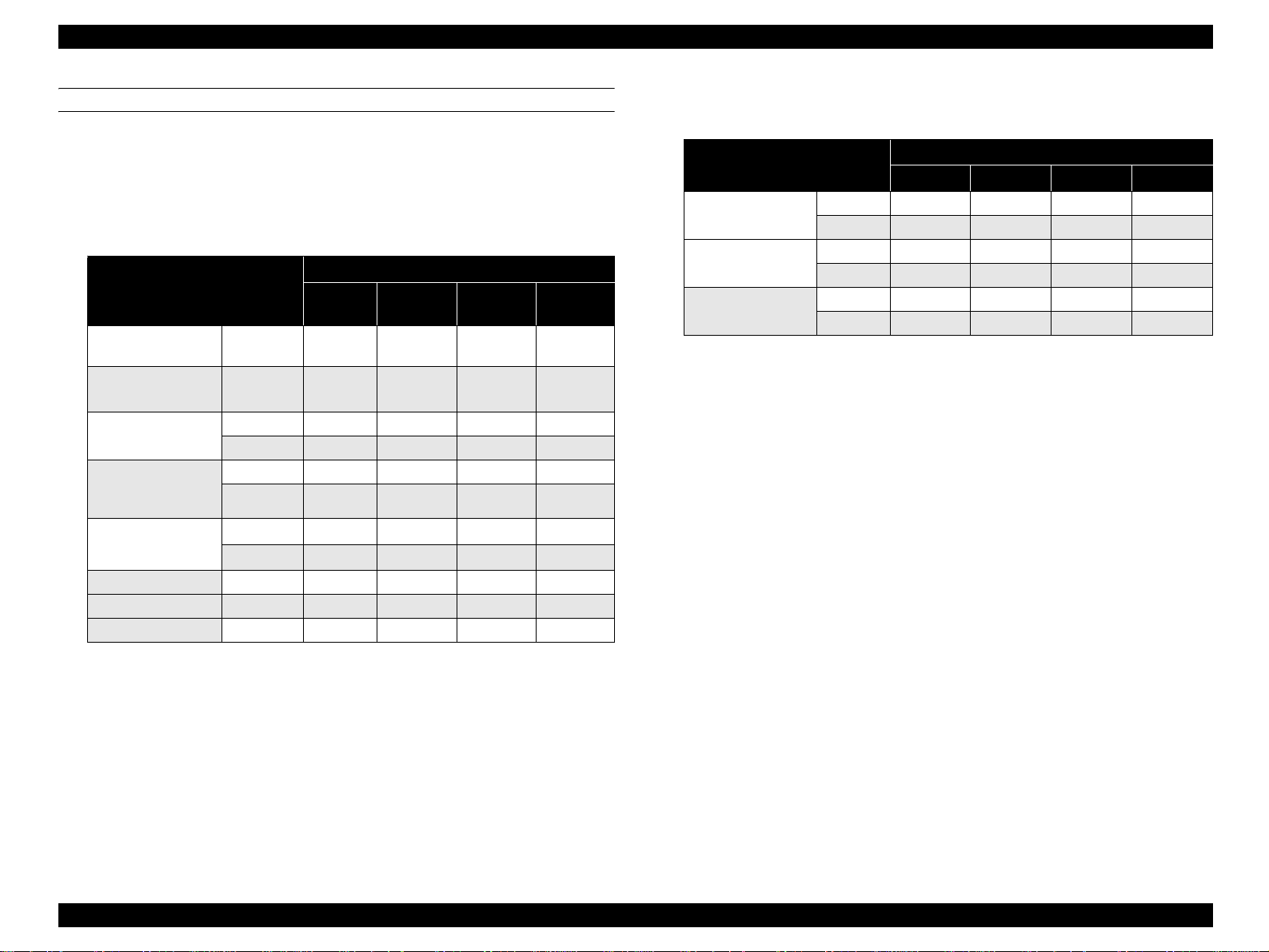
CONTINUOUS PRINTING SPEED
Note that the time given in the tables below does not apply when the printer is in the
conditions described in “1.11 Engine Restrictions” (p31).
Monochrome mode
*1
Simplex printing
Table 1-4. List of Continuous Printing Speed (Unit: ppm)
Printing Speed Mode
Paper Size
LT/Executive JIS-B5/
A5/HL
LT/Executive JIS-B5/
A5
A4
Legal13” (GLG)
Legal14” (LGL)
F4
Envelop/DL/ISO-B5/
GLT
LT and under MP tray 35.2 17.6 11.7 8.2
LT ~ A4 MP tray 33.7 16.8 11.2 8.0
A4 ~ Legal14” (LGL) MP tray 29.4 14.7 9.8 7.2
MP tray 35.2 18.3 12.2 8.2
LC1/2/3/4
MP tray 33.7 17.5 11.7 8.0
LC1/2/3/4 35.0 17.5 11.7 8.0
MP tray 29.4 15.2 10.1 7.2
LC1/2/3/4 30.4 15.2 10.1 7.2
MP tray
LC1/2/3/4
Standard 1Low Speed 1Low Speed 2Low Speed
36.6
35.0
*3
–
18.3 12.2 8.2
17.6
– –
*3
3
– – – –
Duplex printing
Table 1-5. List of Continuous Printing speed (Unit: ppm)
Paper Size
LT/Executive JIS-B5/
A5
A4
Legal13” (GLG)
Legal14” (LGL)
Note *1: See “ Supported paper size, type and orientation” (p14) for details of p a per
orientation.
*2: F eed each of the papers at some intervals.
*3: The speed is 35.0ppm onl y when feeding from LC4 .
MP tray 21.0 11.5 7.8 3.4
LC1/2/3/4 21.0 11.5 7.8 3.4
MP tray 20.4 11.2 7.6 3.3
LC1/2/3/4 20.4 11.2 7.6 3.3
MP tray 18.7 10.2 6.9 3.1
LC1/2/3/4 18.7 10.2 6.9 3.1
Standard 1 Low speed 1 Low speed 2 Low Speed
Printing Speed Mode
PRODUCT DESCRIPTION Basic Specifications 11
Page 25
EPSON AcuLaser C4200 Revision A
Color mode
*1
Simplex printing
Table 1-6. List of Continuous Printing Sp eed (Unit: ppm)
Printing Speed Mode
Paper Size
LT/Executive JIS-B5/
A5/HL
LT/Executive JIS-B5/
A5
A4
MP tray 25.1 18.3 12.2 8.2
LC1/2/3/4
MP tray 24.1 17.5 11.7
LC1/2/3/4
Legal13” (GLG)
Legal14” (LGL)
F4
DL/GLT/ISO-B5
MP tray 21.0 15.2 10.1
LC1/2/3/4
MP tray
LC1/2/3/4 – – – –
LT and under MP tray 35.2 17.6 11.7 8.2
LT ~ A4 MP tray 33.7 16.8 11.2 8.0
A4 ~ Legal14” (LGL) MP tray 29.4 14.7 9.8 7.2
Standard 1Low Speed 1Low Speed 2Low Speed
26.2 18.3 12.2
25.0 17.5 11.7
21.7 15.2 10.1
–
18.3
– –
3
8.2
8.0
8.0
7.2
7.2
Duplex printing
Table 1-7. List of Continuous Printing Speed (Unit: ppm)
Paper Size
*2
LT/Executive JIS-B5/
A5
A4
Legal13” (GLG)
Legal14” (LGL)
Note *1: See “ Supported paper size, type and orientation” (p14) for details of paper
orientation.
*2: Feed each of the papers at some intervals.
MP tray 15.2 11.5 7.8 3.4
LC1/2/3/4 15.2 11.5 7.8 3.4
MP tray 14.8 11.2 7.6 3.3
LC1/2/3/4 14.8 11.2 7.6 3.3
MP tray 13.6 10.2 6.9 3.1
LC1/2/3/4 13.6 10.2 6.9 3.1
Standard 1 Low Speed 1 Low Speed 2 Low S peed 3
PAPER FEED REFERENCE
Reference position to feed paper (in any size) is always center of the feeders.
Printing Speed Mode
PRODUCT DESCRIPTION Basic Specifications 12
Page 26
EPSON AcuLaser C4200 Revision A
PAPER FEED
Table 1-8. Paper Feed
Feeder
MP tray
Standard
550-sheet
cassette (LC1)
Duplex unit
(built-in)
550-sheet
paper casset te
Option
(LC2, 3, 4)
Note *1: Refer to “1.3 Paper Specifications” (p19).
*2: Environmental condition for the capacity: 22 ºC/55% RH.
Sheet Capacity/
Height Capac ity
150 sheets
150 sheets
15 mm
15 mm Transparencies: A4, LT –
15 mm Labels: A4, LT –
15 mm
15 mm envelopes, DL, ISO-B5 75 to 105 g/m
15 mm
550-sheet
61mm
–
550-sheet
61mm
Paper Type*1/Paper Size
Standard paper:
EPSON High Quality Plain Paper
Standard paper: RX-80
Plain paper/recycled paper:
A4, A5, B5, Letter, GLT, HLT,
Executive, F4 , LGL13”, LGL1 4”
Thick Paper/Extra Th ic k Paper:
A4, A5, B5, LT, GLT, HLT, Ex ecut ive
User defined size
Width 88.90mm to 220.00mm
Length 139.70mm to 355.6 0mm
A4, A5, LT, B5, Executive,
LGL13” (GLG), LGL14”
A4, A5, LT, B5, Executive,
LGL13” (GLG), LGL14”
A4, A5, LT, B5, Executive,
LGL13” (GLG), LGL14”
4024 Paper (20lb)
Available Paper
Basis Weight
2
82 g/m
2
80 g/m
2
75 g/m
60 to 105 g/m
106 to 163 g/m
164 to 216 g/m
60 to 216 g/m
60 to 105 g/m
64 to 163 g/m
60 to 105 g/m
2
2
2
2
2
2
2
2
COMBINATION WITH OPTIONAL CASSETTE
By attaching two types of optional paper feed cassette, the paper supply capacity can
be increased as follows.
*2
MP tray 150 sheets { { { {
Standard
550-sheet paper
cassette
(LC1)
550-sheet paper
cassette
(LC2)
Option
1100-sheet paper
cassette
(LC3/4)
Note : These values are valid with RX-80 paper (80 g/m2) and EPSON high quality plain paper
(82 g/m
Table 1-9. Combination with Optional Cassette
Combination (1) (2) (3) (4)
550 sheets { { { {
550 sheets – { – {
1100 sheets – – { {
Total Capacity
2
).
700
sheets
1250
sheets
1800
sheets
sheets
2350
PRODUCT DESCRIPTION Basic Specifications 13
Page 27
EPSON AcuLaser C4200 Revision A
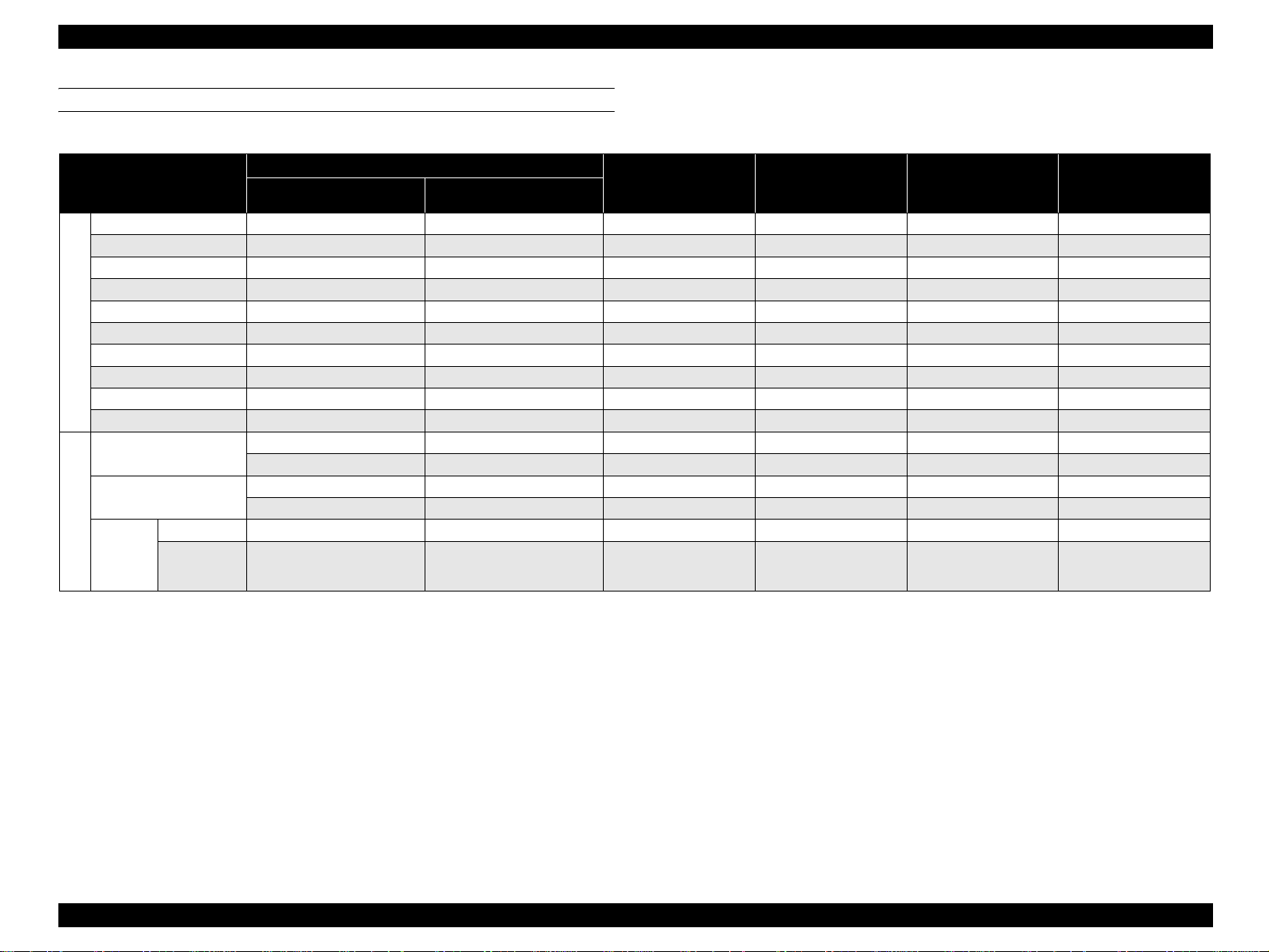
SUPPORTED PAPER SIZE, TYPE AND ORIENTATION
Table 1-10. List of Supported Paper Size, Type and Orientation
Paper size D imensions in mm (inches)
Paper
Vertical (length) Horizontal (width)
MP Tray
A4 297.00 210.00 { SEF z
A5 148.00 210.00 { SEF z
LT 279.40 (11.00") 215.90 (8.50") { SEF z
HLT 215.90 (8.50") 139.70 (5.50") { – SEF –
GLT 266.70 (10.50") 203.20 (8.00") { – SEF –
EXECUTIVE 266.70 (10.50") 184.15 (7.25") { SEF z
Standard
LGL13” (GLG) 330.20 (13.00") 215.90 (8.50") { SEF z
LGL14” 355.60 (14.00") 215.90 (8.50") { SEF z
F4 330.00 210.00 { – SEF –
User defined paper size 139.70 to 355.60 (5.5" to 14") 88.90 to 220.00 (3.5" to 8.5") { – Discretionary –
Transparency
Labels
*2
DL 110.00 220.00 {*
A4: 297.00 A4: 210.00 { – SEF –
LT: 279.40 LT: 215.90 { – SEF –
A4: 297.00 A4: 210.00 { – SEF –
LT: 279.40 LT: 215.90 { – SEF –
3
Special paper
ISO-B5 250.00 176.00 {*
3
envelopes
Note *1: : Feeding is possible and paper size is automatically detected.
*2: {: Feeding is possible by specifying the size code with the controller.
*3: z: Duplex printing is available.
*4: –: Not available
*5: SEF (Short Edge Feed): Set paper to be loaded from its short side.
*6: LEF (Long Edge Feed): Set paper to be loaded from its long side.
*7: See “Envelope orie ntation” (p.15) for details of details of envelop orientation.
550-sheet Paper
Cassette
Paper Orientation Duplex Printing
(STD/OPT)
– LEF –
– SEF –
PRODUCT DESCRIPTION Basic Specifications 14
Page 28
EPSON AcuLaser C4200 Revision A
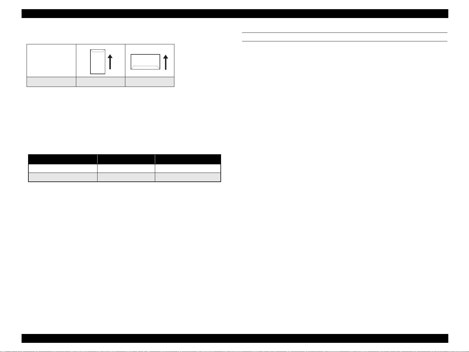
Envelope orientation
Paper feed direction
Envelope type DL ISO-B5
Note *1: Set envelopes with its print surface facing down.
*2: Image quality and feed is not guaranteed when printing on the back side (flap side)
of envelopes.
*3: Envelopes with adhesive or tape are not available.
Printing surface set direction
Table 1-11. Printing Surface Set Direction
MP tray Optional paper cassette
Set direction (Printing surface) Face down Face up
Paper feed direction Top edge first Bottom edge first
PAPER EJECT CAPACITY
Number of sheets: 250 sheets, face down only (A4/LT, Standard paper)
Thickness: 36 mm (Paper ejection automatically stops when the sensor
detected that the ejected papers has built up to a thickness of
36 mm)
Note : Environmental conditions for the capacity: 22 °C/55 % RH, standard paper (simplex/
duplex printing).
PRODUCT DESCRIPTION Basic Specifications 15
Page 29
EPSON AcuLaser C4200 Revision A
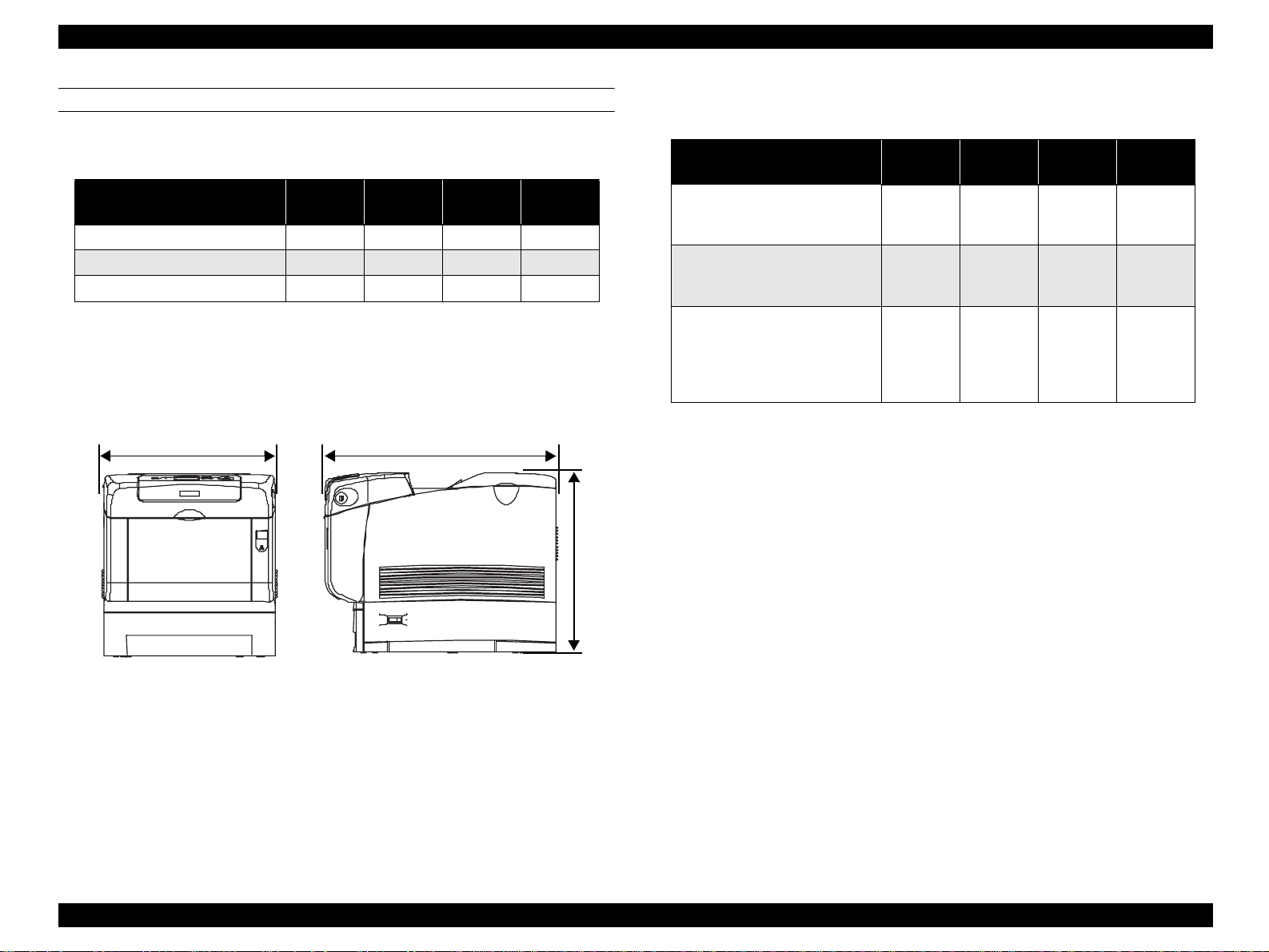
DIMENSIONS AND WEIGHT
Dimensions and weight of each unit
Table 1-12. Dimensions and Weight
Width
(mm)
Main unit 437 588 457 31.5
550-sheet paper cassette 429 509 154 7
1100-sheet paper casset te 584 695 364 21
Note 1: Manufactu rin g tole r ance is ± 5 mm in dimensions and ± 0.5 kg in wei gh t.
2: Consumables (Toner cartridges and Photoconduc to r unit) are not included in the main
unit weight (controller is included).
437mm 588mm
Depth
(mm)
Height
(mm)
Weight
(kg)
Dimensions and weig ht wi th options installed
Table 1-13. Dimensions and Weights with Options In stalled
Width
(mm)
Main unit
+
550-sheet paper cassette
Main unit
+
1100-sheet paper cassette
Main unit
+
550-sheet paper cassette
+
1100-sheet paper ca sette
Note 1: Manufacturing tolerance is ± 5 mm i n dimensions and ± 0.5 kg in weight.
2: Consumabl e s (Toner cartridges and Photoconductor unit) are not included in the main
unit weight (controller is included).
457mm
437 588 584 39
584 695 796 53
584 695 923 60
Depth
(mm)
Height
(mm)
Weight
(k)
Figure 1-1. Dimensions (Main Unit)
PRODUCT DESCRIPTION Basic Specifications 16
Page 30
EPSON AcuLaser C4200 Revision A
CONSUMABLES AND PERIODIC REPLACEMENT UNIT
Table 1-14. List of Consumables and Periodic Replacement Unit
Classification Replacement Unit
Toner cartridge
(Black, Cyan, Yellow, Magenta)
Consumables
Periodic replacement units
Note : For detailed specifications, refer to “1.9 Consumables/Periodic Replacement Unit”
(p27).
Photoconductor unit
Transfer unit
Fuser unit
Retard Roll
Developer Unit Assy.
Feed Roll Assy. MP
Retard Roll Assy. MP
Regi Roll Assy.
Feed Roll Assy. CST
POWER SUPPLY
Power supply operating voltage/frequency
AC 120 V ± 10 % 50 Hz /60 Hz ± 3 Hz
AC 220 V/240 V ± 10 % 50 Hz /60 Hz ± 3 Hz
Power supply for the controller
DC 5.0 V± 5%, 1 A or less
DC 3.3 V± 5%, 3 A or less
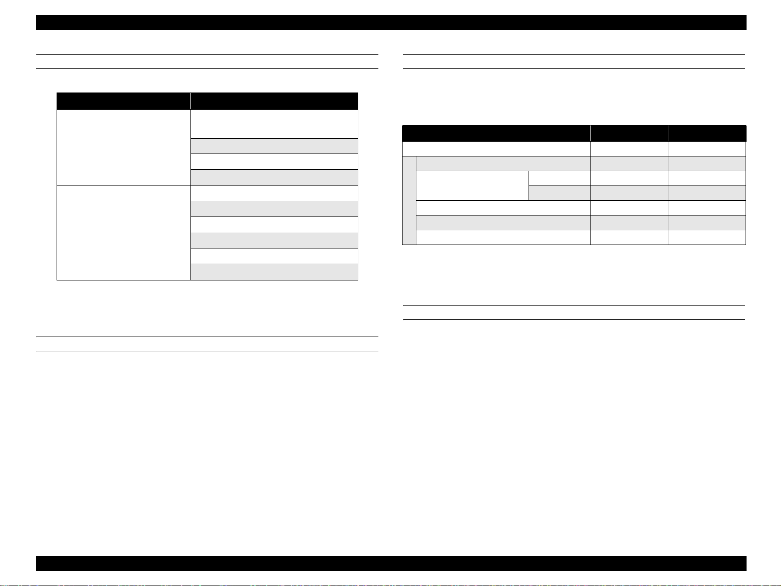
POWER CONSUMPTI ON
The maximum rated current and power consumption are measured with all engine
options and controller options installed.
Table 1-15. List of Power Consumption
110 V 240 V
Maximum rated current 10 A 5 A
Maximum 900 W 960 W
Continuous printing average
Average during standby with the heater on 70 W 71 W
Average in low power mode wit h th e heater off
Power consumption
Power supply off 0 W 0 W
Note : International Energy Star Standards: Color printer with 20 ppm print speed or higher:
45W or less
Color 357 W 354 W
Monochrome 437 W 426 W
21 W 25 W
CONSUMPTION CURRENT
550-sheet paper cassette (option)
5 V/ 0.1 A or less
24 V/ 0.5 A or less
1100-sheet paper casette (option)
5 V/ 0.1 A or less
24 V/ 0.3 A or less
PRODUCT DESCRIPTION Basic Specifications 17
Page 31

EPSON AcuLaser C4200 Revision A
NOISE
Main unit
Item Printing Mode Standby M ode Sleep Mode
Sound pressure 55 dB 35 dB Background noise
Sound power 6.65 B 5.0 B Background noise
Note 1: The method of measuring and calculation conforms to ISO-7779 and ISO-9296.
2: Values mentioned above are actual measurement value.
EXHAUST GAS
Ozone density: 0.02 mg/m
Styrene density: TBD mg/m
Dust density: 0.075 mg/m
TVOC: TBD mg/m
3
or less (the measuring method conforms to BAM)
3
or less
3
or less (the measuring method conforms to BAM)
3
or less
PRODUCT DESCRIPTION Basic Specifications 18
Page 32

EPSON AcuLaser C4200 Revision A
1.3 Paper Specifications
1.3.1 Paper Type
Standard paper
Monochrome: RX-80 paper, 4024 paper (20 lb)
Color: EPSON Color Laser Paper
Plain paper
64 g/m
2
to 105 g/m
(Commonly used copy paper, recycled paper, high quality plain paper)
Recommended recycled paper: Steinbeis Recycling Copy classic
Special Media
EPSON transparency sheets (A4)
Labels
Thick paper (106 g/m
Envelope
C H E C K
P O I N T
lb: Ream weight = Total weight of 500 sheets of 17" x 22"
g/m
Before purchasing a large amount of paper, test the paper if it
can be printed normally.
2
2
to 216 g/m2)
sized paper
2
:1g/m2 = 0.2659763 lb
1.3.2 Paper that may cause printing defects, paper jams or printer malfunction
Transfer paper (carbon paper, non-carbon paper), thermal paper, impact paper,
acid paper
Paper that is too thin or too thick
Paper that is wet or damp
Paper with special coatings or color printer paper with processed surfaces
Glossy (too slick) paper, or paper with too rough surface
Paper that the roughness is significantly different by side
Paper with punch holes or perforations
Creased, curled or torn paper
Irregularly shaped paper or paper with non-perpendicular corners
Labels that peel off easily
Paper with glue, staples or paper clips attached to it
Special paper for ink jet applications (super-fine, glossy, glossy film, etc.)
Paper previously used in a thermal or ink jet printer
Transparencies for other color laser printers or color photocopiers
Paper that has been already printed by other color/monochrome laser printers or
photocopiers
Sheets of paper stuck together
Postcards for ink jet printers, unofficial postcards, and adhesive postcards
Iron print coated paper (for both ink jet and laser printers)
Paper that is deteriorated or discolored, due to temperatures lower than 190 ºC.
When postcards with illustrations are used, the paper feed roller may be soiled
with paper dust, and these post cards may no t be fed proper ly. In this case, cleaning
is required in accordance with “ MAINTENANCE” (p451)
PRODUCT DESCRIPTION Paper Specifications 19
Page 33

EPSON AcuLaser C4200 Revision A
1.3.3 Available Paper by Feeder
Table 1-16. Types of Paper Feed
Special Paper
Paper Feed
MP tray {
Duplex unit
(built-in)
550-sheet
paper cassette
(LC1/2/3/4)
Note 1: {: Paper feeding and image quality is guaranteed.
2: : Paper feeding and printin g is possible. However, this is limite d t o typ es of pa pe r for
3: X: Feeding is not possible.
Standard
Paper
{ X X X X
{ X X X X
general applications. Image quality is not guaranteed.
Plain
Paper
Trans-
parency
Labels
Thick
Paper
Extra
Thick
Paper
Enve-
lopes
1.3.4 Printing Area
MAXIMUM PRINTABLE AREA
Paper with 355.60 mm length or less
Width: 210.90 mm x Length: 351.60 mm
Note : Printing prohibited areas for any type of paper are as follows;
Right and left margins: 2.5 mm
Top and bottom margins: 2.0 mm
GUARANTEED PRINTING AREA
The guaranteed printing area is sho wn b elow. Th e min imum left, rig ht, to p an d bottom
margins are 4 mm for any type of paper.
4mm4mm
4mm4mm
Guaranteed
printing area
Figure 1-2. Guaranteed Printing Area
PRODUCT DESCRIPTION Paper Specifications 20
Page 34

EPSON AcuLaser C4200 Revision A
1.4 Reliability and Serviceability
1.4.1 Reliability
MECHANICAL LIFETIME
Table 1-17. Mechanical Lifetime
Unit Lifetime
Main unit 600,000 pages or 5 years, whichever comes first.
550-sheet paper cassette (option) 600,000 pages or 5 years, whichever comes first.
1100-sheet paper cassette (option) 600,000 pages or 5 years, whichever comes first.
MPBF
Table 1-18. MPBF
Unit Lifetime
Main unit 100,000 pages
Optional Feeder 100,000 pages
PAPER FEED RELIABILITY
PRINTING START POSITION ACCURACY
Table 1-20. Printing Start Position Accuracy
Simplex Printing Duplex Printing
Main scanning direction
Reference point (c)
Sub-scanning direct ion
Reference point (a)
a
c
±2.5 mm ±2.5 mm
±2.0 mm ±2.0 mm
b
Printable area
d
e
Feed direction
f
Table 1-19. Paper Feed Reliability
Standard Paper Plain Paper Special Paper
Reliability Issue
MP Tray
Simplex 1/3,000 1/5,000 1/2,000 1/3,000 1/100 –
Jam rate
Duplex 1/1,800 1/3,000 1/1,200 1/1,800 – –
Multiple-sheet feed rate 1/1,500 1/2,500 1/1,000 1/1,500 1/50 –
Note 1: Environmental conditions: Normal operating environment
2: Paper size: Regular size
3: Humidity: Newly unpacked paper
4: Paper type: The 550-sheet paper cassette does not use special p aper (Refer to
“Supported paper size, type and orientation” (p.14))
5: Multiple -sheet feed rate: Cond itio n s when adding new paper on to rema in ing paper in
the tray or cassette are not considere d.
550-sheet
Paper
Cassette
MP Tray
550-sheet
Paper
Cassette
550-sheet
MP Tray
Paper
Cassette
Figure 1-3. P rinting Start Position Accuracy
PRODUCT DESCRIPTION Reliability and Serviceability 21
Page 35

EPSON AcuLaser C4200 Revision A
SKEW
Table 1-21. Skew
A4 Simplex Printing Duplex Printing
Main scanning direction (| a-b |) 1.2 mm 1.2 mm
Sub-scanning dir e c tio n (| c-d |) 0.8 mm 0.8 mm
Table 1-22. Length Standard of Measurement
Simplex printing
Duplex printing
HEIGHT OF CURL OF OUTPUT PAPER
Table 1-23. Height of Curl of Output Paper
Paper Type Curl Height
Standard paper , Plain paper 30 mm or less
Other special papers No regulation
Note 1: The same for simplex and duplex printing
2: Measurement conditio ns: 22 ºC/55% at low speed 2
Main scanning direction (e) 19 0mm
Sub-scanning direction (f) 114.5 mm
1.4.2 Durability
PRINT VOLUME (PAGES/MONTH)
Average : 3, 000 pages/month
Maximum : 90, 000 pages/month (monochrome:color = 1:1)
1.4.3 Serviceability
A4
MEAN TIME TO REPAIR
MTTR : Average 30 minutes or less
(Time required for service personnel to determine and correct the
cause of the malfunction)
PRODUCT DESCRIPTION Reliability and Serviceability 22
Page 36

EPSON AcuLaser C4200 Revision A
1.5 Service Conditions
AMBIENT TEMPERATURE AND HUMIDITY
Table 1-24. Ambient Temperature and Humidity
Temperature (ºC) Humidity (%RH) Other
Operating 5 to 32 15 to 85
Non-operating -20 to 40 5 to 85
AIR PRESSURE (ALTITUDE)
65 to 101 kPa (0 to 3,100 m or less)
LEVELNESS
Difference between front and back: 10 mm or less (at 445 mm)
Difference between left and right: 10 mm or less (at 445 mm)
No condensation
SPACE REQUIREMENTS
In order to ensure that the printer operates properly, provide at least as much space as
shown in the diagram below.
350mm
100mm
100mm
100mm
150mm
ILLUMINATION
3,000 lx or less (do not expose to direct sunlight)
Figure 1-4. Space Requirements
PRODUCT DESCRIPTION Service Conditions 23
Page 37

EPSON AcuLaser C4200 Revision A
1.6 Conditions for Storage and Transport
AMBIENT TEMPERATURE AND HUMIDITY
Main unit
Table 1-25. Ambient Temperature and Humidity (Main unit)
Condition Temperature (°C) Humidity*1 (%RH) Guaranteed Period
Normal
conditions
Harsh
conditions
Note *1: Non-condensing
High 35 to 40 High 80 to 95
Low -20 to 0 Low 5 to 15
0 to 35 15 to 85
Optional products
Table 1-26. Ambient Temperature and H umidity (Optional products)
Condition Temperature (°C) Humidity*1 (%RH) Guarantee period
Normal
conditions
Harsh
conditions
Note *1: Non-condensing
High 50 to 60 High 85 to 95 Max. 48 hours
-20 to 50 5 to 85
12 months after
manufacture
Max. 48 hours
12 months after
manufacture
DROPPING
There should be no damage o n 1 co rner , 3 ed ges , an d 6 s i des o f th e p ackages u nder the
conditions below.
Table 1-27. Dropping
Drop
Standard Main unit 640 mm
Option
550-sheet paper casset te 910 mm
1100-sheet paper cassette 760 mm
VIBRATION
There should be no damage under the following conditions
Frequency: 5 to 55 Hz
Acceleration: 1.5 G
However, between 5 to 10 Hz, constant 7.5 m m d ouble
amplitude is assumed.
Frequency sweep: Logarithmic sweep 10 minutes for one-way
Direction of application: X, Y, Z directions
STORAGE ALTITUDE
Number of cycles: 3 cycles for each of XYZ directions (each 1 hour)
0 to 3,100m or less
For air trans port, 0 to 15, 000m. Howev er, this assumes that the cargo compartment is
maintained at 70.9275 kPa or higher.
PRODUCT DESCRIPTION Conditions for Storage and Transport 24
Page 38

EPSON AcuLaser C4200 Revision A
1.7 Electrical Characteristics
NOTE: The following sections do not include any optional units.
ELECTRICAL FAST TRANSIENT/BURSTS (AC LINE NOISE)
Ensure the following conditions using evaluation methods compliant with
IEC61000-4-4.
1 kV: No errors excluding insignificant dot errors
2 kV: No damage to parts
INSTANTANEOUS OUTAGES
No effect on printing quality.
DIP: 0.5 cycle 95 %
RESISTANCE TO STATIC ELECTRI CITY
Ensure the following conditions using evaluation methods compliant with
IEC61000-4-2 CISPR 24.
INSULATION RESISTANCE
10 MΩ or more
WITHSTAND VOLTAGE
There should be no break down during application of the voltages shown below.
Leak current should be 20mA or less when applying the voltage for one minute.
Table 1-28. Withstand Voltage
Between Inlet and Non-charged
Metal Parts
120 V AC 2000 V AC 3000 V
200 V series AC 3000 V AC 3000 V
LEAK CURRENT
Between Primary and Secondary
Power Transformers
120 V: 3.5 mA or less
220-240 V: 3.5 mA or less
Contact electric discharge 5 kV:
No error on any device after applying
Aerial electric discharge 10 kV:
No error on any device after applying
INRUSH CURRENT
1/ 2 cycle
100 A or less (0-peak): Including heater inrush
(with cold start or hot start/rated voltage:
± 10 %)
PRODUCT DESCRIPTION Electrical Characteristics 25
Page 39

EPSON AcuLaser C4200 Revision A
1.8 Compatible Specification
SAFETY STANDARD
Table 1-29. Safety Standards
Model Type Applicable Standards
120 V
200 V series
SAFETY STANDARD (LASER TRANSMISSION)
Model Type Applicable Standards
120 V FDA21CFR Chapter 1, Subchapter J, Section 1010, 1040
200 V series
UL60950 3rd Edition
CSA C22.2 No.60950-00
IEC60950 3rd Edition
EN60950 3rd Ed ition
Table 1-30. Safety Standa rds (Laser Transmission)
IEC60825 Class 1 Laser P r oduct
CE Directive
Nordic Agency Approvals
POWER SUPPLY HARMONICS
Not applicable
POWER CONSUMPTI ON
Conforms to International Energy Star Program standards
MISCELLANEOUS
Toner: Have no affect on human body (conforms to OSHA,
TSCA, EINECS)
OPC: Have no affect on human body (conforms to OSHA)
Ozone generation: Conforms to UL478 5th edition
Materials: Does not contain any materials prohibited in each
country, nor harmful substances above the permitted
values
<Reference> Laser specifications:
• Wavelength (shortest to longest): 775 to 799 nm
• Maximum average radiant power: 10 mW
EMI STANDARDS
Table 1-31. EMI Standards
Model Type Applicable Standards
120 V FCC Part 15 Subpart B, Class B (ANSI C63.4)
EN55022 (CIRSP R Publication22 ), Class B
230 V
EN61000-3-2 (Harmonics) Class A
EN61000-3-3 ( Flicker)
PRODUCT DESCRIPTION Compatible Specification 26
Page 40

EPSON AcuLaser C4200 Revision A
1.9 Consumables/Periodic Replacement Unit
C A U T I O N
1.9.1 Specifications
Consumables
Toner Cartridge (K) Toner hopper
Toner cartridge (Y) Toner hopper
Toner cartridge (C,
M)
Photoconductor unit
Transfer un it
Fuser unit
The print page-based service life values of the Consumables and
Periodical Replacement Parts are guidelines. The number of
printable pages changes depending on how they are printed. The
number of printable pages decreases depending on the intermittent
printing (where a few pages, one to several pages, are printed each
time), paper size, paper orientation, thick paper print ing, printed
document, frequent power-on/off, etc. Hence, the number of
printable pages of the consumables and periodical replacement
parts may become less than a half depending on the operating
conditions and environment of the user.
Table 1-32. Consumables
External
*1
*1
*2
Dimensions
(mm)
355 (W)
51 (D)
55 (H)
355 (W)
51 (D)
53 (H)
355 (W)
51 (D)
53 (H)
328 (W)
113 (D)
244 (H)
290 (W)
97 (D)
49 (H)
TBD TBD
Name Configuration Life Time
9,000 pages
(TBD)
8,000 pages
(TBD)
Toner hopper 8,000 pages
Photoreceptor
Developer
Intermediate roll
Transfer
BTR
Waste Toner Box
Heat roll
Quarts lamp (For 120V/
230V)
35,000 pages
(TBD)
35,000 pages
(TBD)
100,000 pages
(TBD)
Weight
(g)
380
350
360
3200
520
Note *1: Approximate number of printed pages using A4 continuous printing at 5% image
occupation rate.
The cartridge lifetime varies accordi ng to the paper size and type of printing (toner
save mode etc.)
Note :Refer to “1.13 Life Details” (p33) for details.
Periodic replacement parts specifications
Table 1-33. Periodic Replacement Parts Specifications
Name Life Time
ROLL ASSY RETARD 100,000 page
DEVE ASSY 300,000 page
ROLL ASSY FEED (MP)
HOLDER ASSY RETARD
CHUTE ASSY REGI 300,000 page
ROLL ASSY FEED (CST) 300,000 page
Note *: Cassette: When the usage rate of MP tray is 85:15
45,000 page
(300,000 page*)
45,000 page
(300,000 page*)
PRODUCT DESCRIPTION Consumables/Periodic Replacement Unit 27
Page 41

EPSON AcuLaser C4200 Revision A
1.9.2 Conditions for Storage and Transport
Temperature and humidity conditions
Condition Temperature (°C) Humidity*1 (%RH) Guarantee Period
Normal
conditions
Harsh
conditions
Note *1: Non-condensing
Note : Storage time after opening is 12 months in the normal operating environment.
High 35 to 40 High 80 to 95
Low -20 to 0 Low 5 to 15
0 to 35 15 to 80
Storage altitude
65 to 101 kPa (0 to 3,100m)
For air transport, 0 to 15,000m. However, this assumes that the cargo compartment
is maintained at 70.9275 kPa or higher.
Package dropping
There should be no damage on 1 co rner, 3 edges , and 6 sid es of the packages under
the conditions below.
Table 1-34. Package Dropping
24 months
(unopened)
Max. of 1 month
Package name Drop
Toner cartridge (Y, M, C, K) 910 cm
Photoconductor unit 910 cm
Transfer unit 910 cm
Fuser unit 910 cm
PRODUCT DESCRIPTION Consumables/Periodic Replacement Unit 28
Page 42

EPSON AcuLaser C4200 Revision A
1.10 External Appearance and Unit Names
1.10.1 Unit Names
Table 1-35. List of Unit Names
No. Name No. Name No. Name No. Name
1 Control panel 7 Power switch 13 Ethernet interface connector 19 Fuser unit
2 Cover B 8 Latch on cover A 14 AC inlet 20 Photo c on ductor unit
3 Top cover 9 Standard lower paper cassette 15 USB interface connector 21 Toner cartridge
4 Output tra y 10 Expansion tray 16 Parallel interface connector 22 Cover D
5 La tch on cover B 11 MP tray (Multi-purpose tray) 17 Type B interface card slot cover
6 Cover A 12 Stopper 18 Transfer unit
Figure 1-5. Unit Name_1
Figure 1-6. Unit Name_2
PRODUCT DESCRIPTION External Appearance and Unit Names 29
Page 43

EPSON AcuLaser C4200 Revision A
Figure 1-7. Unit Name_3
PRODUCT DESCRIPTION External Appearance and Unit Names 30
Page 44

EPSON AcuLaser C4200 Revision A
1.11 Engine Restrictions
1.11.1 Controls that Restrict Print Speed
CLEANING CYCLE
On a temporary basis, printing is interrupted to perform cleaning in the conditions
mentioned below. Necessary time for the cleaning is approximately 25 seconds
(including other controls).
Cleaning may be carried out more frequently depending on the environment.
Table 1-36. Monochrome Mode
Total pages printed with
PHD
0 - 1024 108 54 39
1025 - 5120 108 54 39
5121 - 10240 72 36 26
10241 - 15360 72 36 26
15361 - 20480 72 36 26
20481 - 25600 54 27 20
25601 - 30720 54 27 20
30720 - 54 27 20
Number of pages between each cleaning
Standard Low Speed 1 Low Speed 2/3
Table 1-37. Color Mode
Total pages printed with
PHD
25601 - 30720 26 18 13
30720 - 26 18 13
Number of pages between each cleanin g
Standard Low Speed 1 Low Speed 2/3
COOL DOWN
Printing is temporarily interrupted to cool down the fuser unit in the conditions
mentioned below. Necessary time for the cool down depends on the temperature
of the fuser unit.
1. Temperature of the fuser unit edge exceeded the specified value.
2. Difference in temperature between the edge and the central portion of the fuser unit
exceeded the specified level.
3. Temperature exceeded the higher limit that is set to each type of papers.
4. During continuous printing on small-sized papers, and when starting printing on largesized papers right after printing on small-sized papers.
1.11.2 Controls that Restrict Print Start
Necessary time to start printing may become longer immediately after shifting
the print modes mentioned below.
1. Resolution
Table 1-37. Color Mode
Total pages printed with
PHD
0 - 1024 52 36 26
1025 - 5120 52 36 26
5121 - 10240 35 24 17
10241 - 15360 35 24 17
15361 - 20480 35 24 17
20481 - 25600 26 18 13
Number of pages between each cleaning
Standard Low Speed 1 Low Speed 2/3
2. Monochrome/Color
3. Print speed
4. Paper type
5. Size
1.11.3 Toner Duty Limiting Value
240 % (to prevent fuser unit from twisting paper jam)
PRODUCT DESCRIPTION Engine Restrictions 31
Page 45

EPSON AcuLaser C4200 Revision A
1.12 Notes When Replacing Consumables and Installing Optional Products
1.12.1 Consumables
Toner Cartridge
Toner cartridge can be replaced regardless of whether or not the main unit is
turned on.
Photoconductor Unit
This unit can be replaced regardless of whether or not the main unit is turned on.
BTR
This unit can be replaced regardless of whether or not the main unit is turned on.
Fuser Unit
Turn the printer off.
Leave the printer stand for at least 30 minutes after turning off the power as
the Fuser is extremely hot after use.
Release the fixing levers on both right and left sides.
1.12.2 Optional Products
550 -sheet Paper Casse tte
Turn off the main unit before installing.
If the main unit is on when the cassette is installed, it is not detected.
Secure to the main unit with the attaching parts located on the top surface.
1100-sheet Paper Cassette
Turn off the main unit before installing.
If the main unit is on when the unit is installed, it is not detected.
Secure to the main unit or 550-sheet paper cassette with the attaching parts
located on the top surface.
Adding Controller Option Parts
Turn off the main unit before installing. T he part will be damaged if th e power
is on.
Remove the cover that is located beneath the controller.
Remove the three screws to pull out the cassette.
PRODUCT DESCRIPTION Notes When Replacing Consumables and Installing Optional Products 32
Page 46

EPSON AcuLaser C4200 Revision A
1.13 Life Details
Monochrome mode
Table 1-38. Monochrome mode
Catalog
Unit
Toner cartridge (K)
Phoroconductor unit
Transfer unit
Fuser unit
DEVE ASSY
Note : Values in parentheses are theoretical values and may differ from t he actual
measurement values.
specification
value
9,000 5 % 9,000 9,000 9,000
35,000
35,000
100,000 --- 100,000 100,000
300,000 --- 300,000 300,000 170,000
Area
Coverage
5 % 35,000 35,000 26,800
10 % 35,000 35,000 26,800
20 % 35,000 35,000 26,800
50 % 35,000 35,000 25,600
5 % --- (46,000) (37,000)
10 % --- (45,000) (36,000)
20 % --- (42,000) (34,000)
50 % --- (37,000) (30,000)
Continuous
LIFE (unit: pages)
printing
4 P/J 1 P/J
100,000 or
less
Color mode
Table 1-39. Color mode
Catalog
Unit
Toner cartridge (K)
Toner cartridge (C/
M/Y)
Phoroconductor unit
Transfer unit
Fuser unit
DEVE ASSY
Note : Values in parentheses are theoretical values and may di ffer fro m the actual
measurement values.
specification
value
9,000 5 % 9,000 9,000 9,000
8,000 5 % 8,000 8,000 8,000
35,000
35,000
100,000 --- 100,000 100,000
300,000 --- 300,000 300,000 170,000
Area
Coverage
5 % 35,000 35,000 26,800
10 % 35,000 35,000 25,600
20 % 29,000 29,000 24,100
50 % 12,000 12,000 12,000
5 % --- 35,000 (34,000)
10 % --- (39,000) (31,000)
20 % --- (32,000) (26,000)
50 % --- (22,000) (18,000)
Continuous
LIFE (unit: pages)
printing
4 P/J 1 P/J
100,000 or
less
PRODUCT DESCRIPTION Life Details 33
Page 47

EPSON AcuLaser C4200 Revision A
1.14 Engine Control (Appendix)
Table 1-40. Engine Control
Timing Item Action Prerequisite Operating Time
1. At power-on
2. When opening/closing the covers
once the number of printed pages exceeded 200 pages.
1. The number of accumulated printed pages exceeded 25
pages.
2. Carrying out printing immediately after the power-on.
3. When shifting the print speed in accordance with the change
of paper type.
4. When shifting the res olution.
5. When shifting monochrome/color mode.
1. More than 80 pages are printed within 15 minutes.
2. Temperature has changed more than 6 °C since the last regi
control.
3. After replacing the PHD with a new one.
4. Temperature difference between environment temperature
and the fuser unit at power-on is more than 10 °C.
5. Printing is not carried out for more than 80 minutes.
6. Instruction from the controller.
1. Temperature of the fuser unit edge exceeded the specified
value.
2. Difference in temper ature between the edge and the ce ntral
portion of the fuser unit exceeded the specified level.
3. Tempe rature exceed ed the higher lim it that is set to each typ e
of papers.
42 sec.
110 sec. (including
cleaning operation)
4 ~ 10 sec.
19 sec.
Max. 90 sec.
At power-on
Pre-printing operation
Cleaning
Toner transfer
(Filling toner into the pipe)
Idling the develo per assy
(Cleaning)
Adjusting the CTD sensor
light intensity
Fuser unit warm-up Each time the printer is used. 25 sec.
Fuser unit sensor warm-up Warms the NC sensor When the sensor detected the temperature of -5 °C or less. 90 sec. (at -10 °C)
Process control (SAD) Rea ds t he density and gives feedback.
Regi control Process-directional color registration control
Cool-down of the fuser unit
Retrieves toner accumulated in the cleaner with
the BTR.
Transfers toner into the pipe. When using new printer for the first time. 57 sec.
Repeats idling and cleaning to charge toner. After replacing the developer assy with a new one.
Released when the temperature falls below the
specified level.
PRODUCT DESCRIPTION Engine Control (Appendix) 34
Page 48

EPSON AcuLaser C4200 Revision A
Table 1-40. Engine Control
Timing Item Action Prerequisite Operating Time
HAC mode Applies/Agitates toner. Images with 50 % print rate are continuously printed. 3 ~ 15 sec.
Adjusts the temperature to the one that is set to
each type of papers. (Starts printing when the
temperature is settled to the specified value.)
Waits for the fuser unit to rise in temperature.
Draws the TC patch, reads the density, and
gives feedback.
Including agitation/refill of toner and the
cleaning
Raises in temperature until it reaches the
temperature for stand-by.
When the paper type is changed. 15 sec.
The number of continuous print pages exceeded the specified
value.
1. Temperature of the fuser unit edge exceeded the specified
value.
2. Difference in temper ature between the edge and the ce ntral
portion of the fuser unit exceeded the specified level.
3. When printing on large-sized papers right after printing on
small-sized papers.
4. When continuously printing on small-sized papers.
Width = 150 mm or less:20 pages
Width = 186 mm or less:30 pages
Print jobs are temporarily stopped when shifting the following
print modes.
1. Resolution
2. Monochrome/Color
3. Print speed
4. Paper type (When the current temperature is higher than the
predetermined l e vel)
5. Paper size
When the temperature of the fuser unit continues to fall during
printing.
The number of accumulated print pages is more than 25 pages. 9 sec.
Density of the TC patch is thinner than the specified level. 65 sec.
Instruction from the controller. 25 sec.
During printing
(Print jobs are temporarily
stopped or dela yed in o rder to
perform the items right.)
After printing operation
Others
Adjusting the temperature
of the fuser unit (stand-by)
Cleaning
Cool-down of the fuser unit
Shifting the print mode
Reduction in temperature of
the fuser unit
Process control (TC)
Toner refill
Cleaning Each time the printing is finished. 13 sec
Lateral regi control Executes during stand-by. Instruction from the controller. 47 sec.
Fuser unit warm-up
PRODUCT DESCRIPTION Engine Control (Appendix) 35
Page 49

EPSON AcuLaser C4200 Revision A
1.15 Controller Specifications
1.15.1 Controller Basic Specifications
CPU: Po werPC750FX (600MHz)
Enhanced technology: CPGI, CRIT, RIT (FMV)
RAM
DIMM specification: DDR333 200 pin SO DIMM, CL=2.5
Number of slot: Two slots
(the standard RAM must be installed to slot-1)
Standard: 128 MB
Max.: 6 40 MB
Expansion: 12 MB, 256 MB, 512 MB
(SO DIMM)
ROM: 32-bit width (3.3V)
Program ROM: 16 MB (DIMM)
Font: In Program
Expansion ROM: 1 slot (ROM DIMM slot, 3.3V)
Printer Settings: Panel settings, EJL, PJL, HTTP, SNMP, and ENPC
Stores in 256K bytes serial type of EEPROM
NOTE: Expansion ROM can be installed and removed onl y when turning off the
printer.
Slot A: P5C ROM module
Control Panel: LCD 22 digits, 5 lines, 3 LEDs, 6 buttons
Interface
Standard
• Parallel: 1 ch (IEEE1284 compliant bi-directional B-type
connector, Compatibility, Nibble, ECP)
• USB: 1 ch (Rev.2.0 HS), (D4 supported)
• Network: 1 ch (10Base-T/100Base-TX)
• Type-B: 1 slot (Level 3 compatible)
Option: 1 slot (Level 3 compatible)
HDD: 1 (Optional) (supports 40GB h igh-capacity type)
PRODUCT DESCRIPTION Controller Specifications 36
Page 50

EPSON AcuLaser C4200 Revision A
Printer mode
Standard: ESC/ Page-Color, FX (B/W), ESCP2 (B/W),
I239X (B/W), ESC/Page (B/W), Adob e PostS cri pt 3
Option: PCL5c
Other: EJL, PJL, and RCC mode (firmware up grades)
DIAG mode (Engine adjustment),
EpsonNetConfig (Web)
Auxiliary software: Status sheet, Reserv e Job List, Form Overlay List,
Network Status Sheet,
USB Ext I/F statusSht (only when connecting with
EPSON D4 compliant device),
AUX Status Sheet (only when Type-B level 3 is
installed), PS3 Status Sheet,
Font Sample (for each mode),
Hex Dump,
Support Mode,
Printer Adjust Menu,
Maintenance Mode (engine status sheet),
Update function for engine firmware.
Installation method: Slide lip method: installed from the backside of the
main unit
1.15.3 External Interface Specifications
The printer provides the following host interfaces.
Parallel (IEEE1284 compliant) interface: Standard
Ethernet (100BaseTX/10BaseT): Standard
USB (Rev.2.0 HS) interface: Standard
Optional Interface (Type-B) 1 slot: Optional
The locations of the respective interfaces are shown below;
Optional I/F
Ethernet I/F
<Orange LED>
- ON: 100BaseTX
- OFF: 10BaseT
<Orange LED>
- ON: 100BaseTX
- OFF: 10BaseT
1.15.2 Controller Configuration
The factory default of this printer controller configuration is as follows.
USB I/F
Parallel I/F
Paper size: A4
Figure 1-8. Location of External Interfaces
PARALLEL INTERFACE SPECIFICATIONS
CMD: EJL, ESCPAGE-04, ESCPAGECOLOR-01, POSTSCRIPT, PJL, PCL*1;
Note *1: Only when P5C ROM module is installed
PRODUCT DESCRIPTION Controller Specifications 37
Page 51

EPSON AcuLaser C4200 Revision A
ETHERNET INTERFACE SPECIFICATIONS
Printing protocols
TCP/IP: LPR, FTP, IPP, PORT2501, PORT9100
Microsoft Network: Net BIOS over TCP/IP, Net BIOS over NetBEUI
NetWare:
Operating mode
Standby (factory default), NDS Print Server, Bindery Print Server,
Remote Printer
AppleTalk
Management protocols
TCP/IP: SNMP, HTTP, TELNET, DHCP, BOOTP, APIPA, PING, DDNS,
mDNS
*1
, SNTP, SSDP, ENPC
*2
Microsoft Network: Auto-IP, SSDP
MS Network(NetBEUI): SNMP, ENPC
NetWare: SNMP, ENPC
AppleTalk: SNMP, ENPC
Note *1: mDNS is for Rendezvous use.
*2 : These information should not be disclosed to users.
*2
*2
*2
USB INTERFACE SPECIFICATIONS
This printer supports USB2.0HS, and carries 18 digits serial ID number for the USB.
The ID number is printed on the bottom of the Status Sheet. (See “Status Sheet”
(p.75).) Each digit describes as follows;
1, 2: Specific number for the printer model (36)
3: Page Printer (P)
4 to 13: Serial number of the unit
14: The year of an assembly day (lowest digit)
15, 16: The month of an assembly day
17, 18: The day of an assembly day
When the printer is connected to the computer by the USB port, the interface does not
support D4. However, D4 support is available if the EPSON external LAN option is
connected.
The CMD of Device ID differs from the parallel interface with D4L3 being added.
CMD: EJL, ESCPAGE-04, ESCPAGECOLOR-01, POSTSCRIPT, PJL, PCL*1, D4L3*2;
Note *1: Only when P5C ROM module is installed
*2: Available only for US B p ort
Entity type: See the followin g table
Table 1-41. Entity Type
Emulation Entity Type
PS LaserWriter
ESC/Page Color EPSONPAGECOLOR1
ESC/Page
I239X EPSONPRPXL24
FX EPSONFX
ESCP2 EPSONLQ2
*1
PCL5C
Note : Only when P5C ROM module is installed
EPSONPCL5C
PRODUCT DESCRIPTION Controller Specifications 38
Page 52

EPSON AcuLaser C4200 Revision A
OPTIONAL INTERFACE SPECIFICATIONS
Main System Type: MTP1200dpi, PW10200dt1200dpi, PRG (*****) rev,
AP800ma, SPD0fast, D4
Note : The asteri sks ***** indicate the ROM version
Printer Name: Same as the Product Name of the factory default
Product Name: Short Product Name (AL-C4200)
Emulation Type: See the following table
Entity Type: See the following table
Table 1-42. Emulation Type an d En ti ty Typ e
Emulation Emulation Type Entity Type
PS POSTSCRIPT-00 LaserWriter
ESC/Page Color ESCPAGECOLOR-01 E PSONPAGECOLOR1
ESC/Page ESCPAGE-04
I239X PRPXL24-01 EPSONPRPXL24
FX ESCP9 EPSONFX
ESCP2 ESCPL2 EPSONLQ2
*1
PCL5C
Note *1: Only when P5C ROM module is installed
PCL5C-00 EPSONPCL5C
PRODUCT DESCRIPTION Controller Specifications 39
Page 53

EPSON AcuLaser C4200 Revision A
1.16 Control Panel
1.16.1 External Appearance and Names
Table 1-43. Indicators
Indicators Function
LCD 5 lin e x 22 c ha racters (132 x 65 dot matrix)
Ready LED
Data LED
Error LED
Button
Name
Start
/Stop
Cancel Job
(1)
(2)
On: Printer is ready to print.
Off: Printer is not ready to print.
On: Printer conta ins data that has not bee n processed yet.
Off: Printer has finished processing all print data.
Flashing: Printer is currently processing data.
Flashing 1: An error has oc curred which permits continuing to pri nt by pre ssing the Sta rt/
On: An error has occurred which require s the us er t o remove the cause of the error .
Flashing 2: An erro r has occurred which requires the user to cl ear the error and press the
Stop button.
Start/Stop button.
When Ready to Print When Not Ready to Print Error Has Occurred In Panel Setting Mode
1. Pressing normally:
Into pause (not ready to print)
status
1. Pressing normally:
Deletes printing data
2. Pressing for 2 seconds or longer:
Deletes all printing data
Enters the printe r informatio n menu
(3)
in the panel setting mode
Enters the printe r informatio n menu
in the panel setting mode
Enters the printe r informatio n menu
in the panel setting mode
Into On Line (ready to print) statu s
2. Pressing for 2 seconds or longer:
Ejects paper forcib ly
1. Pressing normally:
Deletes printing data
2. Pressing for 2 seconds or longer:
Deletes all printing data
Enters the printer information menu
in the panel setting mode
Enters the printer information menu
in the panel setting mode
Enters the printer information menu
in the panel setting mode
Data LED (Yellow)
Cancel Job button
Table 1-44. Summary of Button Functions
1. Recoverable error:
Clears error
2. Non-recoverable error:
Displays “Unable Clear Error”
1. Pressing normally:
Deletes printing data
2. Pressing for 2 se conds or longer:
Deletes all printing da ta
Invalid
Invalid
Invalid
Returns to normal mode
(the same state as before entering panel setting mode)
Invalid
1. When panel setting mode menu is di splayed: Displays setting item
2. When setting item for non-execution is displayed: Displays setting value
3. When setting item for execution is displayed: Executes printing or processing
4. When setting value is displayed: Re gi ste rs th e set ti ng va l ue
1. When panel setting mode menu is di spla ye d: Ret urns to normal mode
2. When setting item or setting value is displayed: Displays the previ ous hi gher rank in hierarchy
1. When panel setting mode men u is di spla ye d: Displays the previous panel set ti ng m ode menu
2. When setting item is displayed: Displ ays pr evi ous setting item
3. When setting value is displayed: Displays previous setting value
LCD
“ (2)” button
“ (1)” button
Ready LED (Green )
“ (3)” button
“ (4)” button
Figure 1-9. External View of Control Panel
Error LED (Red)
Start/Stop button
PRODUCT DESCRIPTION Control Panel 40
Page 54

EPSON AcuLaser C4200 Revision A
Table 1-44. Summary of Button Functions
Button
Name
(4)
When Ready to Print When Not Ready to Print Error Has Occurred In Panel Setting Mode
Enters the printe r informatio n menu
in the panel setting mode
Enters the printer information menu
in the panel setting mode
Invalid
1. When panel setting mode menu is di splayed: Displays the next panel setting m od e m en u
2. When setting item is displayed: Displays ne xt settin g it em
3. When setting value is displayed: Displays next setting value
PRODUCT DESCRIPTION Control Panel 41
Page 55

EPSON AcuLaser C4200 Revision A
1.16.2 Panel Settings List
The printer settings are listed below.
NOTE: Underlined value in the Setting value column are factory default settin gs.
Information Menu
Setting Setting Values
Status Sheet –
Reserve Job ListM
Form Overlay List
NetworkStatus Sheet
Color Resist Sheet –
AUX Status Sheet
USB Ext I/FStatusSht
PS3 Status Sheet –
PS3 Font List –
ESC/Page Font Sample
P5C Font Sample*
ESCP2 Font Sample –
FX Font Sample –
1239X Font Sample –
C Toner
M Toner
Y Toner
K Toner
Photocon
Transfer
Fuser
*7
*7
*7
*7
*7
*7
*7
Total Pages
*1
*2
*3
*4
*5
*6
8
–
–
–
–
–
–
–
E******F to EF
E******F to EF
E******F to EF
E******F to EF
E******F to EF
E******F to EF
E******F to EF
*7
0 to 99999999
Setting Setting Values
Color Pages
B/W Pages
*7
*7
0 to 99999999
0 to 99999999
Note *1: Only displayed when print jobs are registered in the Quick Print Job.
*2: Only displayed and execut a ble when there is any Form Over lay exists.
*3: Onl y displayed and executabl e when the "Network I/F=On".
*4: Onl y displayed when a level3-supported Type-B host interface is connected and
turning the power on with "AUX I/F=On".
*5: Only displayed when a D4-comp lia n t USB is con ne ct e d an d tur nin g on the power
with "USB I/F=O n".
*6: Not displayed on the panel, only executable in EJL. Should not be exposed to users.
*7: This item is for display only and cannot be modified.
*8: Only displayed when the P5C mod ule is insta lled.
Tray Menu
Setting Setting Values
MP Tray Size
LC1 Size
LC2 Size
LC3 Size
LC4 Size
*2
*1,*2
*1,*2
*1,*2
MP Type Plain, Letterhead, Recycled, Color, Transparency, Labels
LC1 Type Plain, SemiThk, Letterhead, Recycled, Color
LC2 Type Plain, SemiThk, Letterhead, Recycled, Color
LC3 Type Plain, SemiThk, Letterhead, Recycled, Color
LC4 Type Plain, SemiThk, Letterhead, Recycled, Color
Note *1: Displayed according to the installation status of the optional lower cassette .
550-sheet paper cassette is installed: displays up to LC2
1100-sheet paper cassette is installed: displays up to LC3
A4*1, A5, B5, LT, HLT, LGL,GLT, GLG, EXE, F4, MON,
C10, DL, C5, IB5
A4, A5, B5, LT, LGL, GLG, EXE
A4, A5, B5, LT, LGL, GLG, EXE
A4, A5, B5, LT, LGL, GLG, EXE
A4, A5, B5, LT, LGL, GLG, EXE
PRODUCT DESCRIPTION Control Panel 42
Page 56

EPSON AcuLaser C4200 Revision A
550-sheet paper cassette and 1100-sheet paper
cassette are installed: displays up to LC4
(For details, refer to “Controller Configuration” (p.37).)
*2: This item is for display only and cannot be modified.
Emulation Menu
Setting Setting Values
Parallel Auto, ESCP2, FX, I239X, PS3, P5C
USB Auto, ESCP2, FX, I239X, PS3, P5C
Network Auto, ESCP2, FX, I239X, PS3, P5C
*2
AUX
Auto, ESCP2, FX, I239X, PS3, P5C
*1
*1
*1
*1
Note *1: Only displayed and executable when the P5C ROM module is installed
*2: Onl y displayed and executable when the Type-B interface is installed
Printing Menu
Setting Setting Values
Page Size
Wide A4 Off, On
Orientation Port, Land
Resolution 300, 600, 1200
RITech On, Off
Toner Save Off, On, Eco
Image Optimum
*2
Top Offset -99.0 t o 0.0 to 99.0mm step 0.5mm
Left Offset -99.0 to 0.0 to 99.0mm step 0.5mm
T Offset B -99.0 to 0.0 to 99.0mm step 0.5mm
L Offset B -99.0 to 0.0 to 99.0mm step 0.5mm
Note *1: Paper size (width x length) for CTM (custom) are min. 88.9 x 139.7mm and ma x.
220 x 900mm. “Max. 220 x 355.6” is displa yed on the printer driver.
Except service warranty for the paper width is up to 207.9mm.
A4, A5, B5, LT, HLT, LGL, GLT, GLG, EXE, F4, MON,
C10, DL, C5, C6, IB5, CTM
*2
*3
*1
Auto, Off, On
*2: Not valid for P5C .
*3: Eco is not display e d on the panel, only s e ttable in EJL. Shoul d not be exposed to
users.
PRODUCT DESCRIPTION Control Panel 43
Page 57

EPSON AcuLaser C4200 Revision A
Setup Menu
Setting Setting Values
Lang
Langue
Sprache
Lingua
IDIOMA
SPRÅK
Sprog
Taal
Kieli
Líng.
SPRÅK
Time To Sleep
*7
Time Out 0, 5 to 60 to 300 step 1
Paper Source Auto, MP, LC1, LC2*1, LC3*1, LC4
MP mode Normal, Last
Manual Feed Off, 1st Page, EachPage
Copies 1 to 999
Quantity
Duplex
*2
*3
Binding Long Edge, Short Edge
Start Page Front, Back
Paper Type Normal, SemiThk, Thick, ExtraT hk , Tran spar enc y
Page Side Front, Back
Skip Blank Page
*4,*6
Auto Eject Page Off, On
Size Ignore Off, On
Auto Cont Off, On
Englishv
Français
Deutsch
Italiano
ESPAÑOL
SVENSKA
Dansk
Neder lands
SUOMI
Português
Norsk
5, 15, 30, 60 , 120, 180, 240 Min
*1
1 to 999
Off, On
Off, On
Setting Setting Values
Page Protect
*6
Auto, On
LCD Contrast 0 to 8 to 15
Panel Lock
*5
Off, On
Note *1: Displayed according to the installation status of the optional lower cassette .
550-sheet paper cassette is installed: displays up to LC2
1100-sheet paper cassette is installed: displays up to LC3
550-sheet paper cassette and 1100-sheet paper
cassette are installed: displays up to LC4
*2: N ot displayed on the panel, only executable in EJL and PJL. Not saved i n the
EEPROM.
*3: Duplex printing is only available for A4, A5, B5, LT, LGL, EXE, and GLG sized
papers. Simplex printing is available for other sizes of papers.
*4: Valid for ESC/Page, ESC/P2, FX, 1239X.
*5: N ot displayed on the panel or printed on the status sheet. Sett a ble in EJL and
EpsonNet WebAssist, etc.
*6: Not valid for P5C .
*7: Supports the STANDBYTIME command (nonpublic) of EJL. The default setting is
60 minutes.
Color Regist Menu
Setting Setting Values
Cyan Regist
Magenta Regist
Yellow Regist
Note *1: Setting values are saved on the engine controller at the next printing, and the panel
*1
*1
*1
display returns to "0".
-36 to 0 to 36 step 1
-36 to 0 to 36 step 1
-36 to 0 to 36 step 1
PRODUCT DESCRIPTION Control Panel 44
Page 58

EPSON AcuLaser C4200 Revision A
Reset Menu
Setting Setting Values
Clear Warning
Clear All Warnings
Reset
Reset All
SelecType Init
Quick Print Job Menu
Setting Setting Values
User xxxxxxxxxxxxxx
*2
Job
*3
Copies
*3, *4
Delete
Note *1: Not displayed when none of the Verify job, Re-print job, or Stored job are registered.
*2 : To display this item, select Value (User name) and press Enter while the user is
displayed.
*3: To display, select, and execute this item, select Value (Job name) and press Enter
while the job is displayed. After the execution, the printer will cancel the SelecType
mode.
*4: Returns to Job display aft er ex e cu tin g D el et e an d r et urns to User display if all the
jobs are completed. The printer will cancel the SelecType mode if th ere is no user.
*1
xxxxxxxxxxxxxxx
1 to 999
Confidential Job Menu
*1
Setting Setting Values
User xxxxxxxxxxxxxx
Enter Password
*3
Job
*4
Copies
*4, *5
Delete
*2
XXXX
xxxxxxxxxxxxxx
1 to 999
Note *1: Not displayed when Confidential Job is not regist ered.
*2: To display this item, select Value (User name) and press Enter. Use 1 (Back), 2 (Up),
3 (Enter), and 4 (Down) buttons to enter the password.
*3 : Enter the password while Enter Password is displayed. If there is a print job that
matches the password, this item will be displayed.
*4: T o display, select, and execute this item, select Value (Job name) and press Enter
while the job is displayed. After the execution, the pri nter will can cel the Se le cTyp e
mode.
*5: Returns to Job display after executing Delete and returns to User display if all the
jobs are completed. The printer will cancel the SelecType mode if there is no user.
Parallel Menu
*1
Setting Setting Values
Parallel I/F On, Off
Speed Fast, Normal
Bi-D Nibble, ECP, Off
Buffer Size Normal, Maximum, Mi ni mum
Note *1: After this item is changed, the settin g value take s effect after a warm boot or after the
power is turned on again.
While it is reflected immediately in the Status Sheet and EJL read-back, the actual
change takes effect af ter a warm boot or after the power is turned on again.
PRODUCT DESCRIPTION Control Panel 45
Page 59

EPSON AcuLaser C4200 Revision A
USB Menu
Setting Setting Values
USB I/F
USB Speed
USB ExtI/FConfg
Get IPAddress
IP
SM
GW
NetWare
AppleTalk
MS Network
Rendezvous
USB Ext I/F Init
Buffer Size
Note *1: After this item is changed, the settin g value takes e ffect after a warm boot or a fter the
*1
*1
*2
*3
*3, *4, *5
*3
*3
*3
*3
*3
*3
*3
*1
On, Off
HS, FS
No, Yes
Panel, Auto, PING
0.0.0.0 to 255. 255.255.255
0.0.0.0 to 255. 255.255.255
0.0.0.0 to 255. 255.255.255
On, Off
On, Off
On, Off
On, Off
Normal, Maximum, Minimum
power is turned on again.
While it is reflected immediately in th e Status Sheet and EJL read-back, the actual
change takes effect after a warm boot or aft er th e power is turned on again.
*2: Di splayed only when the D4 support USB external device is connected. Changed to
“USB Config=No” automatically when the panel setting mode is finished.
*3: Di splayed only when the D4 support US B ext ernal device is connected, and “USB
external device=Yes”.
Content of the setting depends on the USB external device settings.
*4: T he actual valid value is displayed (but cannot be changed) when “Get IPAddr ess =
Auto”.
*5 : When “Panel” or “PING” is changed to “Auto” in the IP address setting, the printer
stores the previous setting value, which had been set in the “Panel ” or “PING”. The
stored value will be displayed when returning to “Panel” or “PING”.
The printer displays “192.168.192.168” if the settings are not made from the panel.
Network Menu
*1
Setting Setting Values
Network I/F
Network Config
Get IPAddress
*2*3
IP
*2
SM
*2
GW
NetWare
AppleTalk
MS Network
Rendezvous
Link Speed
*1
*2
*2
On, Off
No, Yes
Panel, Auto, PING
0.0.0.0 to 192.168.192.168 to 25 5. 255.255.255
0.0.0.0 to 255.255.255.0 to 255.255.255.255
0.0.0.0 to 255.255.255.255 to 25 5. 255.255.255
*2
*2
*2
*2
*2
On, Off
On, Off
On, Off
On, Off
Auto, 100 Full, 100 Half, 10 Full, 10 Half
Buffer Size Normal, Maximum, Mi ni mum
Note *1: After this item is changed, the settin g value take s effect after a warm boot or after the
power is turned on again.
While it is reflected immediately in the Status Sheet and EJL read-back, the actual
change takes effect af ter a warm boot or after the power is turned on again.
*2: Displayed only when “Network Config=Yes”. (Except these information can be
printed on the stat us sheet regardless of the settings of I/F or Config.)
*3: T he actual valid value is di splayed (but cannot be changed) when “Get IPAddress =
Auto”.
When “Panel” or “PING” is changed to “Auto” in the IP address setting, the printer
stores the previous setting value, which ha d been set in the “Panel” o r “P I NG”. The
stored value will be displayed when returning to “Panel” or “PING”.
PRODUCT DESCRIPTION Control Panel 46
Page 60

EPSON AcuLaser C4200 Revision A
AUX menu
*1, *2
Setting Setting Values
AUX I/F On, Off
*3,*4
*3,*4
*3,*4
*3
*3,*4
*3, *4,*6
*3,*4
No, Yes
Panel, Auto, PING
0.0.0.0 to 192.168.192.168 to 255.255.255.255
0.0.0.0 to 192.168.192.168 to 255.255.255.255
0.0.0.0 to 192.168.192.168 to 255.255.255.255
On, Off
On, Off
On, Off
On, Off
AUX Config
Get IPAddress
*3, *4, *5
IP
*3, *4
SM
*3,*4
GW
NetWare
AppleTalk
MS Network
Rendezvous
AUX Init
Buffer Size Normal, Maximum, Minimum
Note *1: After this item is changed, the settin g value takes e ffect after a warm boot or a fter the
power is turned on again. While it is refl ected immediately in the Status Sheet and
EJL read-back, the actual change takes effect after a warm boot or after the power is
turned on again.
*2: Di splayed only when the Type-B host interface is installed.
*3 : Only displayed, selectable, and executable when the Type-B host interface is
installed. The mode automatically returns to "AUX Config = No" when the printer
status is switched to Online.
*4: Only displayed, selectable, and executable when "AUX Con f ig = Yes". The setting
value switches to the Online status and becomes valid when the network card
restarts. Therefore, when changing the setting value, if the "AUX status sheet" of the
test print menu is executed before recovering from the panel setting mode, the
previous setting value before the change will be printed.
*5: The actual valid value is displayed (but cannot be changed) when "Get IP Address =
Auto". When "Panel" or "PING" is changed to "Auto" in the IP address setting, the
printer stores the previous setting value, which had been set in the "Panel" or
"PING". The stored value will be displayed when returning to "Panel" or "PING".
*6: Can be displayed and settable when Rendezvous support Type-B is installed.
ESC/Page menu
*1
Setting Setting Values
Auto CR On, Off
Auto FF On, Off
CR Function CR, CR+LF
LF Function CR+LF, LF
FF Function CR+FF, FF
Error Code Ignore, Space
Avoid Error Off, On
PGI On, Off
TriColorSpace Normal, sRGB
CM Media Type Off, Opt1, Opt2
Process Mode 1, 2
Note *1: Not displayed on the panel or the status sheet, only executable in EJL
PRODUCT DESCRIPTION Control Panel 47
Page 61

EPSON AcuLaser C4200 Revision A
P5C menu
*5
Setting Setting Values
FontSource Resident, Download*1, ROM A
*2
Font Number 0 to available (Max 65535)
*3
Pitch
Height
*3
0.44 to 10.00 to 99.99 cpi step 0.01cpi
4.00 to 12.00 to 999.75 pt step 0.2 5 pt
IBM-US, Roman-8, Roman-9,
ECM94-1, 8859-2 ISO, 8859-9 ISO,
8859-10ISO, 8859-15ISO, PcBlt775,
IBM-DN, PcMultiling, PcE.Europe,
PcTk437, PcEur858, Pc1004,
WiAnsi, WiE.Europe, WiTurkish,
WiBALT, DeskTop, PsText,
VeInternati, VeUS, MsPublishin,
Math-8, PsMath, VeMath,
SymSet
PiFont, Legal, UK,
ANSI ASCII, Swedis2, Italian,
Spanish, German, Norweg1,
French2, Windows, McText,
Hebrew7, 8859-8 ISO, Hebrew8,
Arabic8, OCR A, OCR B,
Pc866Cyr, Pc866Ukr, WinCyr,
ISOCyr, Pc8Grk, Pc851Grk,
WinGrk, ISOGrk, Greek8,
Pc862Heb, Pc864Ara, HPWARA
Form 5 to 60*4 to 64*4 to 128 Lines
CR Function CR, CR+LF
LF Function LF, CR+LF
Tray Assign 4, 4K, 5S
Note *1: Only displayed when there is download fonts exist.
*2: Only displayed when an optional font is inserted to the ROM socket.
*3: Either of them is di splayed depending on the selected font type. "Pitch" is displayed
if a fixed pitch font is selected and if a proportional font is selected, "Height" is
displayed. Neither of them is displayed if a bitmap font is selected. There may be
rare occasions that both "Pitch" and "Height" appears at a time. (Changing the Font
Source or the Font Number when PCL5 is not running internally will lead to such
occasion.)
*4: If the A4/LT configuration is set to LT, the default should be 60. If the configu ration
is set to A4, the default should be 64.
*5: Only displayed when the P5C ROM module is installed.
PS3 menu
Setting Setting Values
Error Sheet Off, On
Coloration Color, Mono
Image Protect Off, On
Binary Off, On
PRODUCT DESCRIPTION Control Panel 48
Page 62

EPSON AcuLaser C4200 Revision A
ESCP2 menu FX menu
Setting Setting Values
Font
Pitch 10cpi, 12cpi, 15cpi, Prop.
Condensed Off, On
T.Margin 0.40 to 0.50 to 1. 50 inch step 0.05 in ch
Text 1 to 66 to available (Max: 132) Lines
CGTable
Country
Auto CR On, Off
Auto LF Off, On
Bit Image Dark, Light, Bar Code
Zero Char 0, Ø
Courier, Prestige, Roman, Sans serif, Roman T, Orator S,
Sans H, Script, OCR A, OCR B
PcUSA, Italic, PcMultilin, PcPortugue,
PcCanFrenc, PcNordic, PcTurkish2, PcIcelandic,
PcE.Europe, BpBRASCII, BpAbicomp, Roman-8,
PcEur858, ISO Latin1, 8859-15ISO, PcSl437,
PcTurkish1, 8859-9 ISO, Mazowia, CodeMJK,
PcGk437, PcGk851, PcGk869, 8859-7 ISO,
PcCy855, PcCy866, PcUkr866, PcLit771,
Bulgarian, Hebrew7, Hebrew8, PcHe862,
PcAr864,
PcAr864Ara, PcAr720, PcLit774, Estonia,
ISO Latin2, PcLat866
USA, France, Germany, UK, Denmark, Sweden, Italy, Spain1,
Japan, Norway, Denmark2, Spain2, LatinAmeric, Korea,
Legal
Setting Setting Values
Font
Pitch 10cpi, 12cpi, 15cpi, Prop.
Condensed Off, On
T.Margin 0.40 to 0.50 to 1.50 inch step 0.05 inch
Text 1 to 66 to available (Max: 132) Lines
CGTable
Country
Auto CR On, Off
Auto LF Off, On
Bit Image Dark, Light, Bar Code
Zero Char 0, Ø
Courier, Prestige, Roman, Sans serif, Script, Orator S, OCR
A, OCR B
PcUSA, Italic, PcMultilin,
PcPortugue, PcCanFrenc, PcNordic,
PcTurkish2, PcIcelandic, PcE.Europe,
BpBRASCII, BpAbicomp, Roman-8,
PcEur858, ISO Latin1, 8859-15ISO
USA, France, Germany, UK, Denmark, Sweden, Italy, Spain1,
Japan, Norway, Denmark2, Spain2, LatinAmeric
PRODUCT DESCRIPTION Control Panel 49
Page 63

EPSON AcuLaser C4200 Revision A
1239X menu
Setting Setting Values
Font Courier, Prestige, Gothic, Orator, Script, Presentor, Sans serif
Pitch 10cpi, 12cpi, 15cpi, 17cpi, 20cpi, 24cpi, Prop.
Code Page 437, 850, 858, 860, 863, 865
T.Margin 0.30 to 0.40 to 1. 50 inch step 0.05 in ch
Text 1 to 67 to available (Max: 132) Lines
Auto CR Off, On
Auto LF Off, On
Alt. Graphics Off, On
Bit Image Dark, Light
ZeroChar 0, Ø
CharacterSet 1, 2
Support Menu*
1
This menu sh ould not be disclosed to us ers.
Printer Adjust Menu
*1
This menu sh ould not be disclosed to users.
Setting Setting Values
HDD Format
PS3 HDD Init
LCD Backlight
*2
*2
*3
Auto, On, Off
Note *1: Only displayed when the Support Mode has been selected by a special operation at
power-on.
*2: Can be displayed and executable when the HDD is installed. The capacity of the area
that can be used for PS3 is 2GB.
*3: Cannot be set in EJL or MIB.
PRODUCT DESCRIPTION Control Panel 50
Page 64

EPSON AcuLaser C4200 Revision A
Setting Setting Values
Dev Cleaning
*2 *3
Normal 0 to 1 step 1
SemiThk 0 to 2 step 1
BTR Normal
BTR Label
BTR Thick
BTR ExtraThk
BTR Transparency
BTR Envelope
BTR SemiThk
BTR Coated
Temp Normal
Temp Label
Temp Thick
Temp ExtraThk
Temp Transparency
Temp Envelope
Temp SemiThk
Temp Coated
Transfer Mask
Cleaning Wait
Cleaning Cycle
*2
*2
*2
*2
*2
*2
*2
*2
*2
*2
*2
*2
*2
*2
*2
*2
*2
*2
*2
-20 to 0 to 30 Step 1
-20 to 0 to 30 Step 1
-20 to 0 to 30 Step 1
-20 to 0 to 30 Step 1
-20 to 0 to 30 Step 1
-20 to 0 to 30 Step 1
-20 to 0 to 30 Step 1
-20 to 0 to 30 Step 1
-6 to 0 to 6 Step 1
-6 to 0 to 6 Step 1
-6 to 0 to 6 Step 1
-6 to 0 to 6 Step 1
-6 to 0 to 6 Step 1
-6 to 0 to 6 Step 1
-6 to 0 to 6 Step 1
-6 to 0 to 6 Step 1
0 to 1 step 1
0, 5, 10, 15 sec Step 5
-5 to 0 to 5 Step 1
Feed Offset -3 .5 to 0.0 t o 3.5 mm
Scan Offset -3 .5 to 0.0 t o 3.5 mm
Feed Offset2 -3.5 to 0.0 to 3.5 mm
Scan Offset2 -3 .5 to 0.0 to 3.5 mm
Note *1: Displayed only when the Support Mode has been s elected by a special operation at
power-on. Items within this menu are not localized. While activating this menu, do
not open/close the covers as that leads to an error. Also, print data sh ould not be sent.
*2: Setu p and execution in error status is invalid.
*3 : Exits the panel setting after the execution.
Maintenanc e Me n u
*1
Setting Setting Values
Engine Status Sheet
Print Log Report
Reset C Dev Counter
Reset M Dev Counter
Reset Y Dev Counter
Reset K Dev Counter
Reset TransferCounter
Clear Error Log
*2
*2
*2
*2
*2
*2
*2
*2
–
–
–
–
–
–
–
–
Note *1: Displayed only when the Maintenance Mode has been selected by a special
operation at power-on. Always displayed in English regardless of the Lang setting o f
the Setup menu
*2 : Exits the panel setting after the execution.
PRODUCT DESCRIPTION Control Panel 51
Page 65

EPSON AcuLaser C4200 Revision A
USER SETTING ITEMS OTHER THAN IN THE SETTING ME NU
The following is a list of user settings not included in the Setup menu.
Initialization by the Initialization menu of the Panel does not clear these items.
Item Setting Value D efault Setting Method
Printer Name
MFG in the Device ID
MDL in the Device ID
DES in the Device ID
CID in the Device ID
32-byte character
string
32-byte character
string
32-byte character
string
32-byte character
string
32-byte character
string
Short Product
Name
(Undefined) EJL
(Undefined) EJL
(Undefined) EJL
(Undefined) EJL
EJL,
PrinterName command
PRODUCT DESCRIPTION Control Panel 52
Page 66

EPSON AcuLaser C4200 Revision A
1.16.3 Explanation of Menu and Settings
The following are items specific to this printer.
Information Menu
Color Regist Sheet
This executes Color Regist Sheet (press the Enter button) and prints the sheet for
adjusting registration of each color (C, M, Y, K). Set the value of this result where
each color is the darkest or, where black and each color are in a line to Yellow
Regist, Magenta Regist, and Cyan Regist.
Setting value of each Yellow Regist, Magenta Regist, Cyan Regist returns to “0”
at the next printout after it is restored on controller.
(Refer to Ch5 “Color registration alignment” for details.)
C, M, Y, K Toner
Indicates remaining amount of C (cyan), M (magenta), Y (yellow), K (black) in 7
increments.
(Display only, especially for read-only.)
E * * * * * * F : 100 % ≥ Remaining Toner ≥ 83%
E * * * * * F : 83 % ≥ Remaining Toner ≥ 66%
E * * * * F : 66 % ≥ Remaining Toner ≥ 50%
E * * * F : 50 %≥ Remaining Toner ≥ 33%
E * * F : 33 % Remaining Toner ≥ 16%
E * F : 16 %≥ Remaining Toner ≥ 0%
E F : Remaining Toner = 0%
Photocon/Transfer/Fuser
Life cycle of Photoconductor unit (Transfer unit/Fuser unit) is displayed in 7
increments. (Display only, especially for read-only.)
E * * * * * * F : 100 % ≥ life of photoconductor unit ≥ 83%
E * * * * * F : 83 % ≥ life of photoconductor unit ≥ 66%
E * * * * F : 66 % ≥ life of photoconductor unit ≥ 50%
E * * * F : 50 % ≥ life of photoconductor unit ≥ 33%
E * * F : 33 % life of photoconduc tor un it ≥ 16%
E * F : 16 % ≥ life of photoconductor unit ≥ 0%
E F : life of photoconductor unit = 0%
Total Pages
Displays the number of sheets printed up to now (display only).
Color Pages
Displays the number of sheets printed in color up to now (display only).
B/W Pages
Displays the number of sheets printed in monochrome up to now (display only).
PRODUCT DESCRIPTION Control Panel 53
Page 67

EPSON AcuLaser C4200 Revision A
Tray Menu
MP Type, LC1 Type, LC2 Type, LC3 Type, LC4 Type
This menu specifies the type of paper loaded in the MP Tray, LC1, 2, 3, 4
cassettes.
Paper Type
Setting Value
Plain Plain Paper (copy paper etc.) Plain paper MP, LC1, LC2, LC3, LC4
SemiThk EPSON Color Laser Paper Pla in paper MP, LC1, LC2, LC3, LC4
Letterhead Letter form Plain paper MP, LC1, LC2, LC3, LC4
Recycled Recycled paper Plain paper MP, LC1, LC2, LC3, LC4
Color Color paper Plain paper MP, LC1, LC2, LC3, LC4
Transparency OHP transparency OHP (half-speed) MP
Labels Label paper
Paper Size Paper Type Paper Source Engine Control
Envelopes --- MP tray For Envelopes
HLT, GLT,
F4, CTM
A4, LC1,
LC2, LC3,
LC4
Contents of Setting Engine Control Applicable Tray
Normal
Other than Normal
Normal
ExtraThk,
Transparency
Label paper
(half-speed)
MP tray
Auto; selects the paper source that
matches the specified paper size
from the paper sources where the
paper type speci fied by the mode
matches the setting value for each
tray as shown in the above table.
MP, LC1, LC2, LC3, LC4; selects
the specified paper source
MP tray
MP
Follows MP
type setting
Follows paper
type setting
Follows paper
type setting
Follows paper
type setting
Follows paper
type setting
Table 1-45. Paper Type Display and Command Specification of Driver
Command
PaperType
display of driver
Unspecified – NORMAL – N1: 0 Unspecified
Plain Auto only NORMAL – N1: 1 Plain
Letterhead Auto only NORMAL – N1: 3 Letterhead
Recycled Auto only NORMAL – N1: 6 Recycled
Color Auto only NORMAL – N1: 7 Color
Transparency MP only TRANSPARENCY – N1: 8 OHP
Labels MP only THICK – N1: 9 Labels
Semi-Thick – HIGHQUALITY – N1: 10 HighQuality
Thick – THICK – N1: 0 Unspe cifie d
Extra Thick MP only EXTRATHICK FRONT N1: 0 Unspecified
Extra Thick
(Back)
Coated – COATED – N1: 0 Unspecified
PapaerTray
MP only EXTRATHICK BACK N1: 0 Unspecified
EJL
PAPERTHICKNE
SS
EJL
PAPERFACE
<GS>n1ptE
PRODUCT DESCRIPTION Control Panel 54
Page 68

EPSON AcuLaser C4200 Revision A
Setup Menu
Paper Source
Selects the paper source when Paper Type = Normal.
Auto: Feeds paper from the paper source that loads paper of the specified
paper type and paper size.
MP: Feeds paper from the MP Tray.
LC1: Feeds paper from the LC1.
LC2: Feeds paper from the LC2.
LC3: Feeds paper from the LC3.
LC4: Feeds paper from LC4.
When Page Size is set to envelopes (IB5, DL), HTL, GLT and F4, Paper Source
always selects the MP Tray.
When Paper Type = Thick, ExtraThk, Transparency, Paper Sou rce is always set to
the MP Tray.
Paper Type
This sets the printing speed and color matching (CM).
Refer to “1.24 Paper Handling Algorithm ” (p79).
Page Side
Front: For printing on the front side of ExtraThk paper.
Back: For printing on the back side of ExtraThk paper.
Reset Menu
SelecType Init
This function returns the panel setting values to the factory default.
However, the following panel setting values are not initialized.
Setting values of Yellow Regist, Magenta Regist, and Cyan Regist
PS3 Menu
Binary
Specifies the data format. Applies to received data from internal, AUX, and USB
interface.
On: B in ary dat a
Off: ASCII data
Note : The settings should be as follows to use Binary data.
: Error Sheet = Off
: Job Management = Off
: Not add Ctrl-D (04h) at the en d of a job
Color Regist Menu
Cyan/Magenta/Yellow Regist
This menu is provided to manually adjust the laser scanning position of each color
in relation to the position of Black in 1/4-dot unit of 600 dpi. The adjustment is
made when primarily locating the main unit and when moving it. Additionally the
adjustment is performed if required.
The value can be set from -36 to 36 in 1/unit.
The setting becomes valid after pressing the [
] button.
PRODUCT DESCRIPTION Control Panel 55
Page 69

EPSON AcuLaser C4200 Revision A
Printer Adjust Menu
This setting menu is displayed and selectable only in the Support mode which is
activated by a special operation at power-on. After the powers is turned off and then
back on again, the Printer Adjust menu is removed from the menu. This setting is valid
after power-on or a warm boot. If the setting is changed from its default value, the color
is no longer guaranteed, but this is used during printing of special paper.
Always use the normal mode (not Support mode), and make sure there is no enginerelated service call error. Then, enter the Support mode and perform the task.
Dev Cleaning
When each toner; C/ M/ Y are mixed, removes the debased toner to transfer unit
from developer and supply fresh toner in developer.
The cleaning cycle is performed in the order o f C, M, and Y, and it takes abo ut 135
seconds.
Normal
Set the paper type to inform for engine when printing with PaperType=Normal.
0: Type thin paper for domestic 1: Type thick paper for overseas
Label
Set the paper type to inform for engine when printing with PaperType=Label.
0: Type thin paper for domestic 1: Type thick paper for overseas
BTR Normal
Sets Transfer Current when printing with PaperType=Normal.
This setting applies to both sides of paper that are selectable at “Printer Adjust
Menu”- “Normal”.
Can be set in - 20 to 30 by 1Step. The electricity value changes 5% by a Step.
The lightest printing result is -20, and darkest printing result is 30.
BTR Label
Sets Transfer Current to be used when printing with PaperType=Label.
Same as normal
BTR Thick
Sets Transfer Current to be used when printing with PaperType=Thick.
Same as normal
BTR ExtraThk
Sets Transfer Current to be used when printing with PaperType=ExtraThk.
Same as normal
BTR Transparency
Sets Transfer Current to be used when printing with PaperType=Transparency.
Same as normal
BTR Envelope
Sets Transfer Current to be used when printing with envelop siz e paper.
Same as normal
BTR Se miThk
Sets Transfer Current to be used when printing with PaperType=Sem iThk.
This setting applies to both sides of paper that are selectable at “Printer Adjust
Menu”- “SemiThk”.
Same as normal
BTR Coated
Sets Transfer Current to be used when printing with PaperType=Coated.
Same as normal
Temp Normal
Sets Fuser Temperature to be used when printing with PaperType=Nomal.
Setting value applies for all Normal-L front/back and Normal-H front/back.
Can be set in -6 to 6 by 1 Step. The electricity value changes 1°C by a Step
Lowest fixation is -6
Highest fi xation is 6
Paper curls when the fixation is too high
Temp Label
Sets Fuser Temperature to be used when printing with PaperType=La bel.
Same as normal
Temp Thick
Sets Fuser Temperature to be used when printing with PaperType=Thick.
Same as normal
Temp ExtraThk
Sets Fuser Temperature to be used when printing with PaperType=ExtraThk.
Same as normal
Temp Transparency
Sets Fuser Temperature to be used when printing with PaperType=Transparency.
Same as normal
PRODUCT DESCRIPTION Control Panel 56
Page 70

EPSON AcuLaser C4200 Revision A
Temp Envelope
Sets Fuser Temperature to be used when printing with envelop size paper.
Same as normal
Temp SemiThk
Sets Fuser Temperature to be used when printing with PaperType=SemiThk.
This setting applies to both sides of paper that are selectable at “Printer Adjust
Menu”- “SemiThk”.
Same as normal
Temp Coated
Sets Fuser Temperature to be used when printing with PaperType=Coated.
Same as normal
Transfer Mask
Masks the Transfer Current applied for the leading edge of paper to prevent the
paper from wrapping around the Photoconductor.
0: Do not mask 1: Mask
Cleaning Wait
Sets a time interval in seconds to run a cleaning cycle between pages when
performing a continuous printing. The printer waits for the next page data for the
set time period with its motors ON. If the next page data is not ready for printing
within the time period, the printer runs a cleaning cycle.
During wait time, it consumes life of consumables.
Normally, default (10 seconds) is enough.
Changing the time may be required, with slow host environment and heavy job in
usual.
Saving life of consumables is possible by selecting an appropriate wait time to
reduce total operating time.
Setting Value α Cleaning Cycle
0 48-sheets
-1 43-sheets
-2 38-sheets
-3 33-sheets
-4 28-sheets
-5 24-sheets
Cleaning Cycle
Sets the variable α which determines the time interval of the cleaning cycles.
(5: +50%, ..., 0: 0%, ..., -5=-50%)
Cleaning Cycle = specified value x (10+α) /10
Specified value of cleaning cycle mutates by total print pages of the
photoconductor unit as well as temperature and humidity.
Ex.) When the total printed pag es of the photoco nductor unit is bel ow 5120 sh eets,
at normal temperature and humidity.
PRODUCT DESCRIPTION Control Panel 57
Page 71

EPSON AcuLaser C4200 Revision A
Maintenance Menu
This setting menu is displayed and can be selected only when the Maintenance Mode
has been activated by special operation when the power is turned on. To return the
printer to normal mode, turn the printer off and back o n in a no rmal manner. Basically,
this menu is intended to be used by service personnel. If cover A or B remains open
when the Maintenance Mode is entered, engine-related errors (including Calibrating
Printer) do not occur.
Engine Status Sheet
Pressing the [ ] button starts printing the Engine Status Sheet. (See 9.2
Engine Status Sheet for details). If data remains in the mode, paper is output. Be
sure to switch to the Maintenance Mode after confirming that there are no engine
related service call in the normal mod e (a mode that is not the Maintenance Mode),
then execute. The sheet is printed with the current setting values of RI Tech, Toner
Save and Resolution applied, while the factory default settings are used to the
other settings. Even after printing, the User Default environment (setting) does not
change. The LCD display blinks during printing. The Engine Status Sheet is
always printed as Lang = English regardless of the Lang setting of the Setup
Menu.
Print Log Report
Starts printing the print log sheet when the [ ] button is pressed. Other items
are the same as the Engine Status Sheet.
Reset C/M/Y/K Dev Counter
Resets the life counter of the developer unit of each color, and adds one to the
number of the replacement. This operation should be performed by service
personnel when the developer unit of each color is replaced.
Reset TransferCounter
Resets the life counter of the transfer unit, and adds one to the number of the
replacement. This operation is not required when replacing the transfer unit after
“Worn Transfer Unit” (warning) or “Replace Transfer Unit” (error) occurred.
Perform this operation when replacing the transfer unit under the conditions not
mentioned above. (The condition where neither warning nor error is occurred.)
Clear Error Log
Clears the Error Log List that is stored to be printed on the Engine Status Sheet.
PRODUCT DESCRIPTION Control Panel 58
Page 72

EPSON AcuLaser C4200 Revision A
1.16.4 Special Operations
LIST OF OPERATING FUNCTIONS
The following is a list of the special operating functions supported by this printer.
Do not make these functions (except Hex dump and suppo rt mode val ue initial i zati on)
available to users.
Table 1-46. List of Operating Funct ions
Function Operating procedure
Hex Dump Turn the power on pressing the [Start/Stop] button
Support Mode Turn the power on pressing the [ ] button
Initialization of EEPROM
Panel Setting Value
Initialization
Forced Clear of the Flash
ROM A Module
Program ROM Update
ROM Module Copy
Maintenance Mode
Engine Program Update
RAM Check (all area)
CPU reset in a Service Call
occurrence
Detailed Information Display
in a Service Call occurrence
Ignore EpsonNet ASP in
HDD
Printing of the Error Sheet
Turn the power on pressing the [ ], [Cancel Job], and [Start/
Stop] buttons
Turn the power on pressing the [Cancel Job] butt on
Turn the power on pressing the [ ], [ ], [ ], and
[Cancel Job] buttons
Turn the power on pressing the [ ], [Cancel Job], and [Start/
Stop] buttons
Turn the power on pressing the [S tar t/Sto p] , [Cance l Jo b], and
] buttons
[
Turn the power on pressing the [ ], [ ], [ ], and
[
] buttons
Turn the power on pressing the [Start/Stop], [Cancel Job],
], and [ ] buttons
[
Turn the power on pressing the [Start/Stop], [ ], [ ], and
] buttons
[
Press the [ ], [ ], [ ], [ ], and [Cancel Job]
buttons when a Service Call error occurs
Press the [ ], [ ], and [Canc e l Job] buttons when a
Service Call occurs
Turn the power on pressing the [ ], [ ], and [Cancel
Job] buttons
Press the [ ] button after resetting the CPU when a
Service Call error occurs
PRODUCT DESCRIPTION Control Panel 59
Page 73

EPSON AcuLaser C4200 Revision A
1.17 Printer Status
1.17.1 List of Printer Messages
The following is a list of messages displayed by the printer.
Each message is the one when “Lang = English” is set.
Table 1-47. List of Printer Messages
Display Sort
(Display at power-on)
Service Req Cffff
Service Req Exxx
Formatting HDD Error
Optional RAM Error Status
ROM CHECK Status
RAM CHECK Status
HDD CHECK Status
Unable Clear Error Status
Self Test Status
Reset All Status
Reset Status
Cancel All Print Job Status – 1003 –
Cancel Print Job Status – 1003 –
Reset to Save Error – – –
LC3 Error 001 Error On 40001 –
Check Transparency Error On 4021 {
Paper Jam x x x x Error On 4234 {
Face-down Full Error Flashing 2 4090 –
Wrong Toner uuuu Error On 4237 –
NonGenuineToner uuuu Error Flashing 2 4241 to 4255 {
TonerCart Error uuuu Error On 4238 –
Status – – –
Service call
error
Service call
*1
error
Error LED
status
On (All LEDs
simultaneously)
On (All LEDs
simultaneously)
– –
On –
– –
– –
–
On
–
All flashing
– 1004 –
Status Code Help
6000 –
6001~6999 –
1004 –
Table 1-47. List of Printer Messages
Display Sort
Install uuuu TnrCart Error On 4235 {
Install Photoconductor Error On 4235 {
Install Fuser Error On 4235 {
Install Transfer Unit Error On 4235 {
Clean Sensor Error On 4228 {
Wrong Photoconductor Error
Replace Toner uuuu Error On 4236 {
Replace Photoconductor Error On 4236 {
Replace Transfer Unit Error On 4236 {
Printer Open Error On 4239 –
Install LC1 Error On 4007 –
Install LC2 Error On 4007 –
Install LC3 Error On 4007 –
Manual Feed sss
–
–
–
Can't Print Duplex Error Flashing 1 3005 {
Paper Out ttt *2 sss
Paper Set ttt *2 sss
Print Overrun Error
Mem Overflow Error
Duplex Mem Overflow Error
Invalid Data Error
Invalid HDD Error
Invalid N/W Module Error
Invalid PS3 Error
Invalid P5C Error
Invalid AUX I/F Card Error
Invalid ROM A Error
Write Error ROM A Error On 4006 –
Write Error ROM P Error – 4006 –
*3
*4
*4
Error Flashing 2 1013 –
Error On 4010 –
Error Flashing 1 3003 {
Error LED
status
On
Flashing 1
Flashing 1
Flashing 1
Flashing 1
On
On
On
On
On
On
Status Code Help
4237 –
3000
3001 {
3004
3007 –
4202 –
4240 –
4201 –
4256 –
4014 –
4003 –
–
{
PRODUCT DESCRIPTION Printer Status 60
Page 74

EPSON AcuLaser C4200 Revision A
Table 1-47. List of Printer Messages
Display Sort
Writing RO M A nnn/mmm
Writing RO M P nnn/mmm
Menus Locked Warning – –
(Panel setting display) –
Reserve JobCanceled Warning – 2565 –
Hard Disk full Warning – 2569 –
Form Data Canceled Warning – 2570 –
PS3 Hard Disk full Warning – 2561 –
Can't Print Warning – 2072 {
Collate Disabled Warning – 2013 {
Check Paper Size Warning – 2004 {
Image Optimum Warning – 2002 {
Check Paper Type Warning – 2008 {
Need Memory Warning – 2003 {
Format Error ROM A Warning – 2000 –
Form Feed Status – 1008 –
(When status sheet is being
printed)
Warming Up Status – 1006 –
Calibrating Printer Status – 1014 –
Offline Status – 1001 {
Cancel Print Job (by host) Status – 1003 –
uuuu Toner Low Warning – 2571 {
Worn Photoconductor Warning – 2571 {
Worn Fuser Warning – 2571 {
Worn Transfer Unit Warning – 2571 {
Worn uuuu Dev Unit Warning – 2571 {
Sleep Status – 1007 –
NonGenuine Toner Warning – 2571 {
Ready Status – 1000 –
*6
*6
Status
Status – 1005 –
Error LED
status
–
Status Code Help
1005 –
1010 –
Table 1-47. List of Printer Messages
Display Sort
(Printing) Status – 1009 –
(Communication with inactive I/F) Status – 1012 –
(Job being executed (p rin ting OK)) Status – 1002 –
Error LED
status
Status Code Help
The above list are described in the order of descending priorities (the top item is the
highest on the list of priorities).
Note *1: See “1.17.3 W a rning Messages and Troubleshooting” (p63) for details.
*2: Displays relevant values of the paper source in the panel settings except Auto.
*3: Displays relevant values of the paper size in the panel settings.
*4: Displays relevant values of each paper feed size of the Tray menu in the panel
settings.
*5 : Bit allocations for warning status of consumables are as follows:
bit application
0 Worn Photoconductor
3 Worn Fuser
4 Worn Transfer Unit
6 K Toner Low
7 C Toner Low
8 M Toner Low
9 Y Toner Low
10 Worn K Dev Unit
11 Worn C Dev Unit
12 Worn M Dev Unit
13 Worn Y Dev Unit
14 NonGenuine Toner
*6: nnn = the number of written blocks,
mmm = total number of blocks
PRODUCT DESCRIPTION Printer Status 61
Page 75

EPSON AcuLaser C4200 Revision A
1.17.2 Status Messages and Troubleshooting
The following is the item specific to this printer.
Calibrating Printer
Explanation
This message is one of the Ready messages and indicates that the engine
adjustment is in progress.
At power-on
When adjusting Print Quality
Remedy
Wait for approximately ten seconds to three minutes until the printer recovers
automatically. Do not open/close the cover or turn the power off during this time.
PRODUCT DESCRIPTION Printer Status 62
Page 76

EPSON AcuLaser C4200 Revision A
1.17.3 Warning Messages and Troubleshooting
The following are items specific to this printer.
uuuu Toner Low
Explanation
The remaining amount of each toner (C, M, Y, or K) is low. The remaining
amount is calculated based on the remaining toner sensor of the engine, and
displays the message when the amount is 20 % or less. The uuuu display, which
corresponds to the C, M, Y, and K toner cartridges, indicates the cartridge with
low toner.
Remedy
This warning message is canceled by performing any of the followings:
Execute Clear All Warning in the Reset menu.
Execute Reset in the Reset menu.
C A U T I O N
Never replace the toner cartridge until uuuu Toner Out occurs,
otherwise the remaining toner may spill out.
Worn Fuser
Explanation
The fuser unit comes to the end of life. The print quality is not guaranteed from
this time.
Remedy
This warning message is canceled by performing any of the followings:
Execute Clear All Warning in the Reset menu.
Execute Reset in the Reset menu.
Replace the Fuser with a new one.
C A U T I O N
Replace the fuser unit immediately.
Worn Photoconductor
Explanation
The photoconductor unit comes to the end of life. The print quality is not
guaranteed from this time.
Remedy
Printing can be continued until the “Replace Photoconductor” error appears,
however, the print quality is not guaranteed from this time. This warning message
is canceled by performing any of the followings:
Execute Clear All Warning in the Reset menu.
Execute Reset in the Reset menu.
Replace the Photoconductor unit with a new one.
PRODUCT DESCRIPTION Printer Status 63
Page 77

EPSON AcuLaser C4200 Revision A
Worn Transfer Unit
Explanation
The transfer unit comes to the end of life.
The print quality is not guaranteed from this time.
C A U T I O N
Be aware that performing borderless printing (printing of image
data that exceeds the specified paper size) shortens the life of the
transfer unit.
Reason: The amount of waste toner increases.
Remedy
This warning message is canceled by performing any of the followings:
Execute Clear All Warning in the Reset menu.
Execute Reset in the Reset menu.
Replace the transfer unit with a new one.
Worn uuuu Dev Unit
Explanation
NonGenuine Toner
Explanation
A non-genuine toner cartridge is installed. Printing can be continued.
Remedy
This warning message is canceled by performing any of the followings:
Install genuine toner cartridge.
Execute Clear All Warning in the Reset menu.
Execute Reset in the Reset menu.
Note : If the cartridge is not replaced with genuine toner cartridge, same warning appears on
the panel when the printer is restarted.
The developer unit (DEVE ASSY) comes to the end of life. The print quality is not
guaranteed from this time.
Remedy
This warning message is canceled by performing any of the followings:
Execute Clear All Warning in the Reset menu.
Execute Reset in the Reset menu.
Replace the developer unit with a new one and execute Reset Dev Counter in
the Maintenance menu.
PRODUCT DESCRIPTION Printer Status 64
Page 78

EPSON AcuLaser C4200 Revision A
1.17.4 Error Messages and Troubleshooting
The following are items specific to this printer.
Check Transparency
Explanation
A paper jam has occurred in registration because media other than transparency
was fed when transparency is specified, or transparency was fed when other than
that is specified.
Remedy
Remove both the media already loaded in the MP tray and the media that is
jammed inside the printer from the MP tray side. Open and close cover A. Load
the correct media to start printing again from where the jam occurred.
Paper Jam xxxx
Explanation
A paper jam has occurred.
Engine Status
Fuser Jam Reg Jam Feed Jam Duplex Jam
X (A B) – – – A B
– X (A) – – A 1
– – X (A C) – C A 1, 3
– – – X (B) B 2
– X (A) – X (B) A B 1, 2
X (A B) – X (A C) – C A B 1, 2, 3
– – X (A C) X (B) C A B 1, 2, 3
Note • X: Paper jam has occurred.
• –: Paper jam not occurred.
• Paper jam can occur at two places at a time as described above.
• Preferential order of the display
C → A → B
• Status code
A: bit1, B: bit2, C: bti3
Paper Jam
xxxx
Status bit
4234
1, 2
Remedy
Paper Jam xxxx Remedy
Paper Jam A B Open both cover A and B to remove the jammed pa per (Fuser Jam).
Open cover A to remove the jammed paper (Reg Jam). As necessary,
Paper Jam A
Paper Jam C A
Paper Jam B Open cover B to remove the jammed paper (Duplex jam).
Paper Jam C A B
open cover D and rem ove the Photoconductor unit to remove the
jammed paper.
Open both cassette C and co ver A to remove the jammed paper (Feed
jam).
Open both cassette C and co ver A to remove the jammed paper (Feed
jam). Perform remedy for Fuser jam and Duplex jam if those paper
jams are occurred at the same time.
Install uuuu TnrCart
Explanation
One or more toner cartridges are not installed. The uuuu display, which
corresponds to the C, M, Y, and K toner cartridges, indicates the cartridge that is
not installed. This error also occurs when the new toner cartridge(s) is installed
with the tape attached to it.
Remedy
Open the top cover to install the specified toner cartridge. Remove the toner
cartridge if the tape is attached to it, reinstall the cartridge, and remove the tape.
Face-down Full
Explanation
When the face-down tray is detected as full, the printer stops printing. The paper
that was being output when the error occurred is ejected to the tray.
Remedy
Remove papers on the face-down tray and press the [Start/Stop] button to resume
printing.
PRODUCT DESCRIPTION Printer Status 65
Page 79

EPSON AcuLaser C4200 Revision A
Install Photoconductor
Explanation
The photoconductor unit is not installed or not set correctly.
Remedy
Open cover A and then cover D to install the photoconductor unit. Closing those
covers will automatically releases the error.
Install Fuser
Explanation
The fuser unit is not installed, not set correctly, or broken down.
If “Install Fuser” and “Service Req E101” occur at a time, only the “Ins tall Fus er”
error is displayed on the panel.
Remedy
Turn the power off and let stand at least 30 minutes. Open cover B, install the fuser
unit correctly, and close cover B. The error shou ld be cleared after p ower has been
restored to the printer. If the error rema ins displayed on the panel, rep lace the fuser
unit as it is malfunctioning or the unit may be the one for another models.
Clean Sensor
Explanation
The sensor window for calibrating the engine is contaminated.
Remedy
Open cover A, remove the transfer unit, and clean off the white plastic window
attached to the backside. Closing cover A after reinstalling the transfer unit will
automatically release the error. Refer to Chapter 6 “Maintenance-Cleaning” for
details.
Wrong Photoconductor
Explanation
Improper photoconductor unit is installed.
Remedy
Open both cover A and cover D to install the appropriate photoconductor unit.
Closing cover A and cover D will automatically release the error.
Replace Toner uuuu
Install Transfer Unit
Explanation
The Transfer unit is not installed.
Remedy
Open cover A and install the transfer unit. Closing cover A will automatically
release the error.
Explanation
Printing is stopped as the remaining amount of toner is detected as low based on
the toner-end sensor of each color of the engine and the d ispense time of the ton er.
As printing in the Toner End status does not provide proper color reproductivity,
this error is not released by pressing the Start/Stop button. The uuuu display,
which corresponds to the C, M, Y, and K toner cartridges, indicates the cartridge
with low toner.
Remedy
Replace the toner cartridge(s).
PRODUCT DESCRIPTION Printer Status 66
Page 80

EPSON AcuLaser C4200 Revision A
Replace Photoconductor
Explanation
The photoconductor unit has reached its end of life.
Printing must be stopped in order not to damage the engine.
Remedy
Open cover A and then cover D to install new photoconductor unit. Closing those
covers will automatically releases the error.
Replace Transfer Unit
Explanation
The transfer unit comes to the end of life.
Remedy
Open cover A and replace the transfer unit with a new one. Closing cover A will
automatically releases the error.
Printer Open
Explanation
Either cover A or cover B is open.
Wrong Toner uuuu (uuuu = C, M, Y, or K)
Explanation
The destination for one of the toner cartridges is set incorrectly.
Remedy
Reinstall the appropriate toner cartridges.
NonGenuine Toner uuuu (uuuu = C, M, Y, or K)
Explanation
A non-genuine toner cartridge is installed.
Remedy
Reinstalling the genuine toner cartridge or pressing Start/Stop button will release
the error. If the error is released by the latter operation, the warning "Non Genuine
Toner" will remain displayed.
TonerCart Error uuuu (uuuu = C, M, Y, or K)
Explanation
One or more of the toner cartridges (C, M, Y, or K) is malfunctioning.
Remedy
Remedy
Closing those covers will automatically releases the error.
INSTALL LC1, INSTALL LC2, INSTALL LC3
Explanation
Printing from LC2, LC3, or LC4 cannot be performed because LC1, LC2, or LC3
is not installed correctly.
Reinstall the toner cartridge or replace the toner cartridge with a new one to
release the error. Turn off the printer and then back on again if the error is not
cleared.
LC3 Error 001
Explanation
Several numbers of the optional 550-Sheet Paper Cassette Unit is detected.
Remedy
Remedy
Installing the cassette firmly will release the error.
Turn the printer power off, and remove the second optional 550-Sheet Paper
Cassette Unit.
PRODUCT DESCRIPTION Printer Status 67
Page 81

EPSON AcuLaser C4200 Revision A
1.17.5 Service Call Error Messages
This section shows the service call error message of this printer. (For details, refer to
Chapter3 “TROUBLESHOOTING”.)
SERVICE CALL ERRORS
Table 1-48. List of Service Call Errors
Error
Category
Engine-related
Error Code Explanation
E100 ROS Failure
E101 Fuser Error
E102 NV-RAM Error
E103 CTD Sensor Error
E104 Fan Motor Error
E105 Motor Failure
E106 Firmware Error
E107 Environment sensor Error
E201 ___Y Development Unit Li fe Over 2
E202 __M_ Development Unit Life Over 2
E203 __MY Development Unit Life Over 2
E204 _C__ Devel opment Unit Life Over 2
E205 _C_Y Development Unit Life Over 2
E206 _CM_ Development Unit Life Over 2
E207 _CMY Development Unit Life Over 2
E208 K___ Development Unit Life Over 2
E209 K__Y Development Unit Life Over 2
E210 K_M_ Development Unit Life Over 2
E211 K_MY Development Unit Life Over 2
E212 KC__ Development Unit Life Over 2
E213 KC_Y De velopment Unit Life Over 2
E214 KCM_ Development Unit Life Over 2
E215 KCMY Development Unit Life Over 2
E998 Engine commu nication error
Error
Category
Controllerrelated
Table 1-48. List of Service Call Errors
Error Code Explanation
C0017 CPU error (undefined interruption)
C0081 CPU error (TLB modification exception)
C0082 CPU error (TLB miss exception [Load/Fetch])
C0083 CPU error (TLB miss exception [Store])
C0084 CPU error (address error exception [Load/Fetch])
C0085 CPU error (address error exception [Store])
C0086 CPU error (bus error exception [Fetch])
C0087 CPU error (bus error exception [Load/Store])
C0088 CPU error (SYSCALL exception)
C0089 CPU error (Break exception)
C0090 CPU error (reserving command exception)
C0091 CPU error (unused coprocessor exception)
C0092 CPU error (FPU exception)
C0093 CPU error (TLB exception)
C0094 CPU error (XTLB exception)
C0095 CPU error (cache exception)
C0096 CPU error (Trap exception)
C0097 CPU error (FPU exception)
C0098 CPU error (watch exception)
C0128 to C0254 CPU error (undefined trap)
C0255 CPU error (NMI exception)
C0256 CPU error (divide by 0)
C0257 CPU error (arithmetic overflow)
C0258 CPU error (break occurrence)
C0800 IPL error (controller defect)
C0998 Engine communication error (only at power-on)
C0999 Engine flash ROM has no program data
C1002 Standard RAM error (standard size is undefined, etc.)
C1010 Verification error
C1020 RAM error (slot 0)
C1021 RAM error (slot 1)
PRODUCT DESCRIPTION Printer Status 68
Page 82

EPSON AcuLaser C4200 Revision A
Table 1-48. List of Service Call Errors
Error
Category
Controllerrelated
Error Code Explanation
C1120 ROM checksum error (bit 0 to 7) (program)
C1121 ROM checksum error (bit 8 to 15) (program)
C1122 ROM checksum error (bit 16 to 23) (program)
C1123 ROM checksum error (bit 24 to 31) (program)
C1200 EEPROM writing error
C1210 EEPROM writing times limit
C1400 Engine initialization error
C1500 CCNV hardware error
C1550 Initialization hardware error for SRAM for compression
C1600
C1610 Video series hardware error (VCNV error)
C1700 Loopback test failure of the Network Board
C1702 Network Board is not installed
C1800 Illegal SPD
C1999 Other hardware errors
C2000 Software error
Video series hardware error (including PWM IC
calibration error)
PRODUCT DESCRIPTION Printer Status 69
Page 83

EPSON AcuLaser C4200 Revision A
1.18 Expanding the RAM
When the memory is insufficient, the printer displays the following error messages.
Mem Overflow
Image Optimum
Need Memory
Du plex Mem Overflow
The following methods can be used to clear the errors.
Set the resolution to 300 dpi.
Reduce receive buffer size.
Set unused interfaces to “Not Use”.
C H E C K
P O I N T
To ensure a stable operation, add more memory.
PRODUCT DESCRIPTION Expanding the RAM 70
Page 84

EPSON AcuLaser C4200 Revision A
1.19 Handling Precautions
Precautions When Turning Off the Power
This printer includes internal, nonvolatile memory (EEPROM), which stores
setting values important to operate the printer normally. If the power is cut off
during writing to the nonvolatile memory, the panel settings return to its default, or
a Service Call error may occur when turning the power back on. In addition, HDD
can be connected to this printer. If the power is cut off during writing to the HDD,
HDD error may occur as the values written to the HDD is not guaranteed.
The printer is executing the writing when it is in the following conditions, so never
turn the power off at those timings.
From the time the power is turned on until the Ready LED lights up steadily
When the Ready LED is flashing
When the printer is printing (while the paper feed motor is operating)
To stop printing, perform either Offline or Cancel job.
When the Data LED is on or flashing
Precautions for High Temperature Parts
Since the fuser unit inside the printer becomes very hot, be sure not to touch it
when opening the cover to remove jammed paper or for any other purposes.
PRODUCT DESCRIPTION Handling Precautions 71
Page 85

EPSON AcuLaser C4200 Revision A
1.20 Status Sheet
An example of the printout of the Status Sheet is shown in the Figure 1-10 (p.75).
The printout example is in the case where English is selected.
z
C H E C K
P O I N T
Prints printed date only when time set is synchronized.
MMMM: Month
DD: Day
YYYY: Year
HH: Hour
MM: Minutes
Network Menu
The IP, SM, and GW addresses are printed only when GetIPAddress=Panel, but
not when the value is Auto. If the setting value is changed, the IP address is printed
in the next startup. (The IP address in operation is printed on the Network Status
Sheet.) NetWare, AppleTalk, MS Network, Rendezvous, and Link Speed are
printed.
The language in which the Status Sheet is printed changes
depending on the selected language.
(The sheet is printed in English in 2-byte linguistic area in Asia.)
Name Remaining Amo unt Part Numbers
Transfer Unit E******F 3022
Fuser Unit 120(110-120V)/220(220-240V) E******F 3020/3021
Information
Describes Name (English only, 36-digit), Remaining Amount (10-digit), Warning
(20-digit), and Model Number (30-digit) of consumables that can be replaced by
the user.
"Needed soon" is added when the amount reaches the level where a warning
occurs.
Name Remaining Amount Part Numbers
Toner Cartridge Cyan E******F 0244
Toner Cartridge Magenta E******F 0243
Toner Cartridge Yellow E******F 0242
Toner Cartridge Black E******F 0245
Photoconductor Unit E******F 1109
PRODUCT DESCRIPTION Status Sheet 72
Page 86

EPSON AcuLaser C4200 Revision A
When options installed
The Status Sheet shows the descriptions below:
1. RAM DIMM: Memory size is added to Installed Memory and Available Memory.
2. Type-B I/F: AUX is added to Installed Interface.
3. Lower Cassette: Lower Cassette 2/3 is added to Other Options.
4. HDD: Hard Disk xGB is added to Other Options. Displayed up to one
decimal place.
5. P5C: PC5 is added to Installed Emulation.
Adds 5-digit Version separately by spaces in Firmware Revision.
In the order as Installed Emulation.
Time to Sleep
Sleep Mode = prints only by Enable
Sleep Mode = dose not print by Disable.
PRODUCT DESCRIPTION Status Sheet 73
Page 87

EPSON AcuLaser C4200 Revision A
THE LOWEST DESCRIPTION SECTION OF THE STATUS SHEET
Description Explanation
IAddyme Date of the firmware
*
Axxxx
"*" appears when DIMM can be written
"space" appears when DIMM cannot be written
Color Look Up Table version
"@xxxx" appears when the optional ROM CMTD is installed
in expansion slot
Engine controller version whic h is 10 digit s number starts with
MC
(ex: Engine controller Ver.1.23.45, NVM Ver.0.67.89;
MC1234506789)
MC3012030100
MCxxxxxxxxxx
Last five digits : NVM Version
(Ver. 3.0.10.0)
First five digits : MCU Version
(Ver. 3.0 .12.0)
36PxxxxxxxxxxYMMDD
H
D
3
e When "e" = ECP, when "n" = Nibble, when " " = Compatibility
USB serial number (Reference: See “ USB interface
specifications” (p38))
Latest USB connection Mode
•H: HS
•F: FS
• Space: no connection
Latest USB connection Mode
• D: connected D4 supported device
• Space: D4 no n s up po r te d de vice
Type-B leve l
•3: Type-B L3
• Space: other than L3
PRODUCT DESCRIPTION Status Sheet 74
Page 88

EPSON AcuLaser C4200 Revision A
Description Explanation
JCxxxxxx
ICcccmmmyyykkk
CCCMMMYYYKKK
COLOR CALIBRATION DESCRIPTION
NOTE: This function is implemented in the ser vice utility.
This indicates G: Increase Gradation, D: Increase Definition, 1200: 1200dpi, 600: 600
dpi, and also means 600 dpi, and calibration data for Increase Gradation depending on
combination, and is displayed only when calibration data are registered in the
EEPROM.
This indicates YYYY: Year, DD: Day, MMMM: Month, HH: Hour, and MM: Minute
of the date a nd time whe n the calibration table is created.
6-digit number that starts with JC indicates the number of
paper jam occurred before.
12-digit number that starts with IC indicates the nu mber of the
replacement of the t oner cartridge; cccmmmyyykkk and 12digit number indicates the number of the recovery from the
NonGenuine error.
Those values are separated with a space.
3-digit number for each color (000-255)
Figure 1-10. Status Sheet
PRODUCT DESCRIPTION Status Sheet 75
Page 89

EPSON AcuLaser C4200 Revision A
1.21 Engine Status Sheet/Print Log Report
C A U T I O N
It can be output from the Maintenance Menu. For details, refer to Chapter6
“MAINTENANCE” for the Engine Status Sheet/Print Log Report.
Do not disclose this information to users.
PRODUCT DESCRIPTION Engine Status Sheet/Print Log Report 76
Page 90

EPSON AcuLaser C4200 Revision A
1.22 Color Registration Sheet
This sheet is for checking the amount of differences between Black and Yellow/
Magenta/Cyan in the laser scanning direction (vertical direction and paper feed
direction). Differential amount of each color with Black is quantitatively measured
according to overlap ratio of the cyclic Black pattern and the cyclic Yellow/Magenta/
Cyan pattern where the cycle is different from that of Black.
Feeding direction
Figure 1-11. Color Registration Sheet
PRODUCT DESCRIPTION Color Registration Sheet 77
Page 91

EPSON AcuLaser C4200 Revision A
1.23 Form Overlay List
The following shows the sample of Form Overlay List. The color information (color or
monochrome) of Form that is registered in the last row will be added to all the models
that follows the AcuLaser C4200.
EPSON AL-C4200
Name
Form1
Form2
Form3
Comment Date
A4 Portrait 600dpi
A4 Lanscape 300dpi
A4 Portrait Test
Nov 07
Nov 31
Dec 31
Mode
Color
Mono
Color
Figure 1-12. Form Overlay List
PRODUCT DESCRIPTION Form Overlay List 78
Page 92

EPSON AcuLaser C4200 Revision A
1.24 Paper Handling Algorithm
The relationship between paper type and size is shown below
ENGINE CONTROL, CM
Page Size PaperType
Envelope
*1
Normal —
Other than
Envelope
SemiThk — — — SemiThk
Thick — —
ExtraThk
Transparency — — — — Transparency(PP M Do wn) (0Fh, S) OHP
.
MP or LC1-4 Type
*2
(Video Media TypeType, Gloss
Engine Control
*3
)
CM
EJL
PAPER FACE
Paper
Source
Table 1-49. Engine control, CM
Paper Type
(set by driver)
— — — — — Envelope (06h, H) Plain Paper
Plain
Plain Paper L (00h, N)
Plain Paper H (01h, N)
Refer to P80, “CM 1”
Auto
Specified
Letterhead
Recycled
Color
Transparency Transparency (PPM Dpwn) (0Fh, S) Refer to P80, “CM 1”
Labels Label H (0Ah, S) Refer to P80, “CM 1”
Not specified —
Other than Auto — —
Plain Paper L (00h, N)
Plain Paper H (01h, N)
Plain Paper L (00h, N)
Plain Paper H (01h, N)
Refer to P80, “CM 2”
Refer to P80, “CM 2”
Plain Paper L (00h, H)
Plain Paper L (01h, S)
Plain Paper
Plain Paper H (PPM Down) (0Eh, S)
Labels — Label H (0Ah, S) Plain Paper
Other than labels — Heavier Paper-L (04h, H) Plain Paper
FRONT
BACK
— — — Heavier Paper-H (05h, S) Plain Paper
Note : For details on print speed, refer to “1.2.2 Printer Basic Specifications” (p9).
Note *1: DL, IB5
*2 : Type of paper set by the panel for the paper source where paper is actually fed
*3: N=Normal Gloss,
H=High Gloss,
S=Super High Gloss
PRODUCT DESCRIPTION Paper Handling Algorithm 79
Page 93

EPSON AcuLaser C4200 Revision A
Table 1-50. CM 1
CM Media Type MP or LC1-4 Type
Plain
Letterhead
Off
Option 1 — Option 1
Option 2 — Option 2
Note :For details on print speed, refer to “1.2.2 Printer Basic Specifications” (p9).
Note *1: Type of paper set by the panel for the paper source where paper is actually fed
Recycled
Color
Labels
Transparency OHP
*1
CM
Plain paper
Table 1-51. CM 2
CM Media Type CM
Off Plain paper
Option 1 Option 1
Option 2 Option 2
PAPER SOURCE
Table 1-52. Paper Source
Page Size Paper Type Paper Feeder
Envelope*1, CTM — MP Tray
—
Note *1: In cases not described in the table, the paper source is determined by Paper Source,
paper type specifi ed by driver (host), and algorithm provided by MP or LC1-4 Type.
Note : DL, IB5
ExtraThk
Transparency
MP Tray
DUPLEX
Table 1-53. Duplex
Page Size Paper Type Auto duplex
Normal
A4, A5, B5, LT, LGL, EXE, GLG
Note : Duplex printing is not possible with paper other than the above.
Thick
SemiThk
Effective
PRODUCT DESCRIPTION Paper Handling Algorithm 80
Page 94

OPERATING PRINCIPLES
CHAPTER
2
Page 95

EPSON AcuLaser C4200 Revision A
2.1 Print Process
2.1.1 Print Process Overview
This printer is a “full-color laser printer” that uses the principle of electrophotographic
recording. This printer uses a tandem-type engine that equips exclusive drums and
developer units for each Yellow, Magenta, Cyan, and Black (abbreviated to Y, M, C,
and K), and prints images in full color by laying images of four colors on papers
through the three intermediate drum transfers (IDT1 x 2, IDT2 x 1).
The major steps of the print process are described below.
(1) Charging : The drum surface is charged.
(2) Exposure : Image areas are exposed on the drum by a laser beam.
(3) Development : Image areas on the drum are developed with toner.
(4) Primary transfer : The toner image on the drum is transferred to the
IDT1 (Intermediate Transfer Drum).
(5) Secondary transfer : The toner image on the the IDT1 is transferred to the
IDT2.
(6) Cleaning : The IDT1 is cleaned.
(7) Third transfer : The 4-color complete toner image on the IDT2 is
transferred to the paper.
(8) Cleaning : The IDT2 is cleaned.
(9) Discharging : The electrical charge of the paper is removed.
Drum (Y)
(1) Charging
(2) Exposure
(3) Development
Intermediate
Transfer Drum
(IDT1)
Intermediate
Transfer Drum
(2) Exposure
(3) Development
(4) Primary transfer
(Drum → IDT1)
(5) Secondary transfer
(IDT1 → IDT2)
(IDT1)
(7) Third transfer
(IDT2 → Paper)
Paper
Drum (M) Drum (C) Drum (K)
(1) Charging
(8) Cleaning (IDT2)
(9) Discharging
(1) Charging
(2) Exposure
(3) Development
Intermediate
Transfer Drum
(IDT1)
(11)Cleaning
(Entirely)
(1) Charging
(2) Exposure
(3) Development
(4) Primary transfer
(Drum → IDT1)
(6) Cleaning (IDT1)(6) Cleaning (IDT1)
BTR
(10) Fusing : Toner on the paper is fixed with heat and pressure.
(11) Cleaning : Remnants of toner on the drums and the intermediate
drum transfers are removed.
(10) Fusing
engine principle0001FA
Figure 2-1. Print Process Overview
OPERATING PRINCIPLES Print Process 82
Page 96

EPSON AcuLaser C4200 Revision A
2.1.2 Print Process Diagram
The diagram below illustrates the entire print process.
Most of the main parts involved with printing process are integrated into the PHD
ASSY and the FRAME ASSY DEVE. The diagram below shows their configuration.
Laser beam
Paper feed
Figure 2-3. PHD ASSY and FRAME ASSY DEVE
Ida_Sec06_014GA
Figure 2-2. Print Process Diagram
OPERATING PRINCIPLES Print Process 83
Page 97

EPSON AcuLaser C4200 Revision A
2.1.3 Technical Explanation of Print Process
2.1.3.1 Charging
At the “Charging” process, RTC (Rubber Tube Charger) applies a uniform negative
potential to the drum which rotates at a fixed speed. This process is performed
simultaneously for each of the yellow, magenta, cyan and black colors.
The RTC is a conductive roller and keeps contact with the drum to move together
with it. The HVPS supplies discharge voltages to the RTC, and then RTC
discharges negative DC voltage.
The drum surface is uniformly charged to a negative potential with DC bias
voltage. The Drum surface is made of conductive material coated with a
photosensitive material that becomes insulating in darkness and becomes
conductive when it is subjected to light.
The Refresher is a conductive brush and is negatively charged by negative DC
voltages sent from the HVPS. It attracts positively charged toner on the drum,
which is transferred back to the drum from the IDT. The Refresher also works to
eliminate discharge products.
HVPS
RTC
-
-
-
+
+
-
+
Refresher
Photosensitive Material
Conductive Material
Drum
engine principle0004FB
Drum Surface
engine principle0005FA
Drum Surface
Potential
engine principle0006FA
Figure 2-4. Charging Process
OPERATING PRINCIPLES Print Process 84
Page 98

EPSON AcuLaser C4200 Revision A
2.1.3.2 Exposure
At the “Exposure” process, a laser beam is applied to the negatively charged surface of
the drum to form an invisible electrostatic latent image onto the drum. This process is
performed simultaneously for each of the yellow, magenta, cyan and black colors.
The laser beams for each color emitted from laser diodes in the ROS ASSY are
directed by the rotating polygon mirror, fixed mirrors and lenses, which are
attached to the Scanner Motor Assy in the ROS ASSY to scan across each drum
surface from side to side.
: Laser Beam (Y)
: Laser Beam (M)
Polygon Mirror
Quad Beam
Laser Diode
: Laser Beam (C)
: Laser Beam (K)
Mirror
Lens
Lens
Mirror
Mirror
Figure 2-5. Path followed by the Laser Beam
Mirror
Mirror
Mirror
Mirror
Mirror
Drum (Y)
Drum (M)
Drum (C)
Mirror
Drum (K)
engine principle0007FA
charge on the drum flows to the positive side, and the potential on the surface of
the drum is reduced in the result. The section of the drum surface where the
potential has reduced becomes the electrostatic latent image.
ROS ASSY
(Laser beam)
Conceptual Diagram on the Drum
Laser Beam
Photosensitive
Material
Conductive
Material
:Negative Charge
:Positive Charge
Photosensitive Material
Conductive Material
Drum
engine principle0008FA
Electrostatic latent
image
Leg_Sec06_010FA
Drum Surface
Laser Beam
Electrostatic latent
image
Leg_Sec06_011FA
Drum Surface
Potential
Laser Beam
-V
0
Leg_Sec06_012FA
Figure 2-6. Exposure Process
The laser beam is irradiated according to the print data (image data) from the
printer controller. The laser beam is output only when a pixel data (minute dot
composing the print data) exists. (On parts to be developed by toner, the laser
diode turns ON, and on parts not to be developed, the laser diode turns OFF.)
The drum surface irradiated by the laser beam becomes a conductor, the negative
OPERATING PRINCIPLES Print Process 85
Page 99

EPSON AcuLaser C4200 Revision A
2.1.3.3 Development
At the “Development” process, toner is electrically applied to the invisible electrostatic
latent image on the drum, to form a visible image on it. This process is performed
simultaneously for each of the yellow, magenta, cyan and black colors.
Toner in the Toner Cartridge is stirred by an Agitator, and is supplied to the
DISPENSER ASSY. Then the toner is transferred to the tube that connects the
DISPENSER ASSY and the DEVE ASSY by the Auger in the assy., and then
reaches to the DEVE ASSY by the Auger in the tube. The Agitator and Augers are
spiral-shaped stirrers driven by the toner motor at the rear of the Toner Cartridge.
The amount of toner transferred to the DEVE ASSY is calculated based on the
number of prints. This is called toner dispense and performed using two types of
control (“PCDC” and “ADC”) in combination. Refer to “2.8.4 Process Control
(p125)” for details on the PCDC and ADC.
Toner transferred to the DEVE ASSY and developer (carrier) in the DEVE ASSY
is stirred by the Auger, and are supplied to the Magnet Roll located near the drum
surface. The toner and the carrier are charged by the triboelectricity (toner:
negative, carrier: positive), and they are attracted to each other.
As the carrier is a magnetic body, it is attracted to the magnetized Magnet Roll,
and a uniform layer of carrier is formed on the Magnet Roll by passing through the
Timmer Rod and the Paddle.
NOTE: The magnet Roll is located inside the DEVE ASSY.
The surface of the Magnet Roll is covered with the conductive sleeve. The DB
(Developing Bias) is supplied to the conductive sleeve from the HVPS. The DB
voltage is a negative DC voltage that AC voltage is superimposed on it. The
electrostatic latent image on the drum, the area hit by the laser, carries less
negative charges than the other area on the drum. As the uniform negative charge
on the Magnet Roll is kept at a certain level by the DC voltage, the potential
difference between the Magnet Roll and the drum surface becom es as f ollows; the
electrostatic image area is higher than the Mag net Roll, and the other area is lower
than the Magnet Roll. The superimposed AC voltage vibrates the carrier on the
Magnet Roll surface making it easier for toner to jump to the drum. Thus, the
negatively charged toner on the Magnet Roll is only attracted to the electrostatic
latent image and forms a toner image on the drum. Once the toner adheres to the
image area on the drum, no more toner is attracted to the area as negative charges
of the area are increasd.
TCRU ASSY (Toner Cartridge)
Agitator
Auger
DISPENSER ASSY
Auger
DEVE ASSY
Drum Surface
Figure 2-7. Development Process
Paddle
Auger
Toner Image
engine principle0013FA
Trimmer Rod
HVPS
-
+
Magnet Roll
Drum Surface
Potential
-V
0
: Negative Charge
: Positive Charge
Toner
Carrier
-
-
-
+
-
Drum
+
+
+
-
Ida_06_016A
engine principle0014FA
Developing
Bias
OPERATING PRINCIPLES Print Process 86
Page 100

EPSON AcuLaser C4200 Revision A
2.1.3.4 Primary Transfer (Drum → IDT1)
At the “Primary transfer” process, the toner image formed on the Drum is transferred to
the IDT1 (Intermediate Drum Transfer 1).
This printer equips two IDT1s. The one is for transferring yellow and magenta toner
images, and the other is for transferring cyan and black toner images.
IDT1 is a conductive roll and a high positive voltage is supplied to it from the
HVPS. A negatively charged toner image on the drum is attracted and transferred
to the IDT1 surface that is charged positively. The potential on the Drum surface is
neutralized by the IDT1 at this time.
egative Charge
N
-
-
Drum (Y)
Drum (M)
-
-
-
+
+
+
+
+
+
-
-
IDT1
+
+
+
+
+
+
-
+
-
Positive C
Toner
harge
Drum Surface
(Yellow Toner Image)
Drum Surface
(Magenta Toner Image)
Drum Surface
(Cyan Toner Image)
IDI1Surface
IDI1Surface
Yellow Toner
Image
Magenta Toner
Image
+
+
+
+
IDT1
Cyan Toner
Image
Drum Surface
(Black Toner Image)
+
+
+
HVPS
Black Toner
Image
-
Drum (C)
Drum (K)
+
-
+
+
+
+
-
-
-
-
engine principle0015FA
Figure 2-8. Primary Transfer (1)
Figure 2-9. Primary Transfer (2)
engine priniple0017FA
OPERATING PRINCIPLES Print Process 87
 Loading...