

Page 1
Apex
TM
Action Printer
TM
T-1000 by EPSON
User’s Manual
Y56599116000
Page 2

Where to Get Help
Customer support and service for Epson products are provided by a
network of authorized Epson dealers and service centers throughout
the United States. Epson America provides product information and
toll-free support to its dealers and service centers.
Epson is confident that this policy will provide you with the
assistance you need. For service center and technical support
referrals, please call our Consumer Information number:
l-800-922-891 1.
Options and Supplies
To locate or purchase ActionPrinter
call l-800-873-7766.
TM
accessories or supplies, please
Page 3

Apex
TM
Action Printer
TM
T-1000 by EPSON
®
User‘s Manual
Page 4

Contents
Introduction
Features
About This Manual
Chapter 1 Setting Up
Identifying Printer Parts
Selecting a Place for the Printer
Installing the Paper Feed Knob
Installing and Replacing the Ribbon
Using Continuous-feed Paper
Using Single-sheet Paper
Operating the Control Panel
..........................................
.................................
.............................
.......................
........................ 1-5
....................
......................... 1-9
.............................
.........................
Connecting the Printer to Your Computer
Printer Selection Menus
Chapter 2 SelecType
SelecType Operation
SelecType Tips
Chapter 3 Printer Features
.....................................
Quality and Fonts
Print Size and Character Width
Special Effects and Emphasis
Using Different Character Sets
.............................
................................
..................................
.......................
.........................
........................
...............
1
1
2
l-1
1-2
1-4
1-6
1-18
1-22
1-26
1-28
2-l
2-2
2-5
3-l
3-2
3-3
3-5
3-6
Chapter 4 Troubleshooting and Maintenance
Problem/Solution Summary
Beeper Error Warnings
Cleaning the Printer
................................
Transporting the Printer
.........................
..............................
.............................
4-1
4-2
4-4
4-5
4-6
iii
Page 5

Chapter 5 Defaults and DIP Switches
Default and Initialization Settings
DIP Switch Settings
International Character Sets
.................................
..........................
.....................
5-1
5-2
5-3
5-5
Chapter 6 Technical Specifications
Printing.. .........................................
Paper
Mechanical
Electrical
Environment
Parallel Interface
Data Transfer Sequence
Chapter 7 Command Summary
Introduction
Printer Operation
Data Control
Vertical Motion
Horizontal Motion
Overall Printing Style
Print Size and Character Width
Print Enhancement
Word Processing
Character Tables
User-defined Characters
............................................
........................................
..........................................
......................................
...................................
..............................
.......................................
..................................
......................................
....................................
..................................
...............................
.......................
.................................
...................................
...................................
.............................
Graphics.. ........................................
6-1
6-2
6-2
6-3
6-3
6-4
6-5
6-7
7-1
7-2
7-2
7-2
7-3
7-3
7-4
7-4
7-5
7-5
7-5
7-5
7-6
Appendix
Compatible Interfaces
Installing an Interface
...............................
...............................
#8143 New Serial Interface Board
Index
iv
.....................
A-l
A-2
A-3
A-9
Page 6

Introduction
The ActionPrinter
TM
T-1000 combines low price with high quality printing
and advanced features.
Features
In addition to the high performance and reliability you’ve come to expect
from Epson® printers, this printer offers the following features:
Draft mode for quick printing. The speed of draft printing is 150
characters per second in pica and 180 in elite.
Near Letter Quality (NLQ)
mode for top quality printing. When you
have perfected a document, you can switch to one of two NLQ
fonts-Roman or Sans Serif.
A variety of print styles, including emphasized, double-strike,
condensed, italic, and double-wide.
Selection of typestyles with the control panel.
User-defined characters so you can create and print your own
symbols or characters.
Dot graphics for charts, diagrams, and illustrations.
Easy paper loading.
A ribbon cassette for quick and clean ribbon changing.
The Epson Character Graphics set, which includes character graphics
that are used on IBM® and compatible computers as well as
international characters used by IBM-compatible software.
Introduction 1
Page 7

Introduction
About This Manual
Chapter 1 gives you step-by-step instructions on setting up your new
printer, and Chapters 2 through 6 cover the basic and advanced
functions. Chapter 7 contains a summary of the printer’s commands, and
the Appendix contains information on optional interfaces.
Attached to the cover of this manual is a Quick Reference card
containing the information you need most.
Introduction
2
Page 8

Chapter 1
Setting Up
Identifying Printer Parts
Selecting a Place for the Printer
Installing the Paper Feed Knob
..............................
........................
........................
Installing and Replacing the Ribbon
Replacing the ribbon
Using Continuous-feed Paper
Installing the tractor unit
Loading continuous-feed
Installing the paper guide
Setting top of form
Removing the tractor unit
Using Single-sheet Paper
Installing the paper guide
Automatic paper loading
Reloading during printing
..............................
.........................
...........................
paper
...................... 1-12
........................... 1-14
................................
..........................
.............................
...........................
...........................
..........................
Printing multi-part forms and copies
Operating the Control Panel
Indicator lights
Buttons
.........................................
...................................
Performing the self test
..........................
..............................
....................
.................
1-2
1-4
1-5
1-6
1-8
1-9
1-9
1-16
1-17
1-18
1-18
1-19
1-21
1-21
1-22
1-22
1-23
1-24
Connecting the Printer to Your Computer
Printer
Selection Menus
Choosing from a menu
A quick test
......................................
..............................
............................
...............
Setting Up 1-1
1-26
1-28
1-28
1-28
Page 9
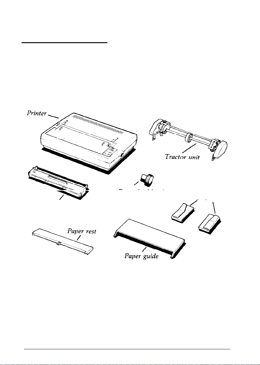
Identifying Printer Parts
First, see that you have all the parts you need. In addition to this
manual, the printer box should contain the items shown in the
illustration below. The paper feed knob is packed into an indentation in
the white foam material.
Ribbon cartridge
1-2 Setting Up
Paper feed knob
Edge guides-
Page 10

Identifying Printer Parts
In addition to the items in the box, you need a proper shielded cable to
connect the printer to your computer. Though unlikely, you may also
need an interface board, which is necessary only for those computers
that can’t use the Centronics® parallel interface. Your computer manual
can tell you which cable you need and whether or not you require a
special interface.
Note: If you plan to use a printer stand, make sure it meets the
following requirements:
l
The stand must support at least
22.4
lb or 10.2 kg (twice the
weight of the printer).
l
The stand must not tilt the printer more than 15 degrees from
horizontal. With a cut sheet feeder, the stand must keep the
printer level.
l
If the paper supply is below the printer stand, make sure that
the paper cannot catch on the underside of the stand or on
the stand supports.
l Make sure that the power cord and the interface cable do not
interfere with paper feeding. If possible, secure them to a
printer stand support.
Setting Up
1-3
Page 11

Selecting a Place for the Printer
The main consideration in selecting a good location for the printer is
placing the printer close enough to your computer for
Also remember the following:
Plug the printer into a grounded outlet, and do not use an adapter
plug. Make sure the power switch on the printer’s left side is off
before plugging in
the
printer.
the
cable to reach.
Avoid using electrical outlets
Accidentally turning off a switch
that
are controlled by wall switches.
can
wipe out valuable information
in your computer’s memory and disrupt printing.
Avoid using
an
outlet on the same circuit breaker with any large
electrical machines or appliances. These can cause disruptive power
fluctuations.
Keep your printer and computer away from base units for cordless
telephones.
Protect the printer from direct sunlight, excessive heat, moisture, and
dust. Make sure that it is not close to a heater or other heat source.
If you are going to use
the
tractor unit and continuous-feed paper, clear
enough space around the printer so that the paper has an unobstructed
path into and out of the printer. There are three common methods of
arranging a printer and continuous-feed paper:
Using a printer stand with the paper stacked behind it. (Because of
the
cable, it is usually best for the paper that feeds into
the
printer to
be stacked somewhat behind the printer instead of directly beneath
it.)
Putting
the
printer on a desk or table and stacking
the
paper behind
the printer.
Using a desk or table as a stand, with the printer near the back edge
and the paper on
1-4 Setting
Up
the
floor or on a shelf.
Page 12
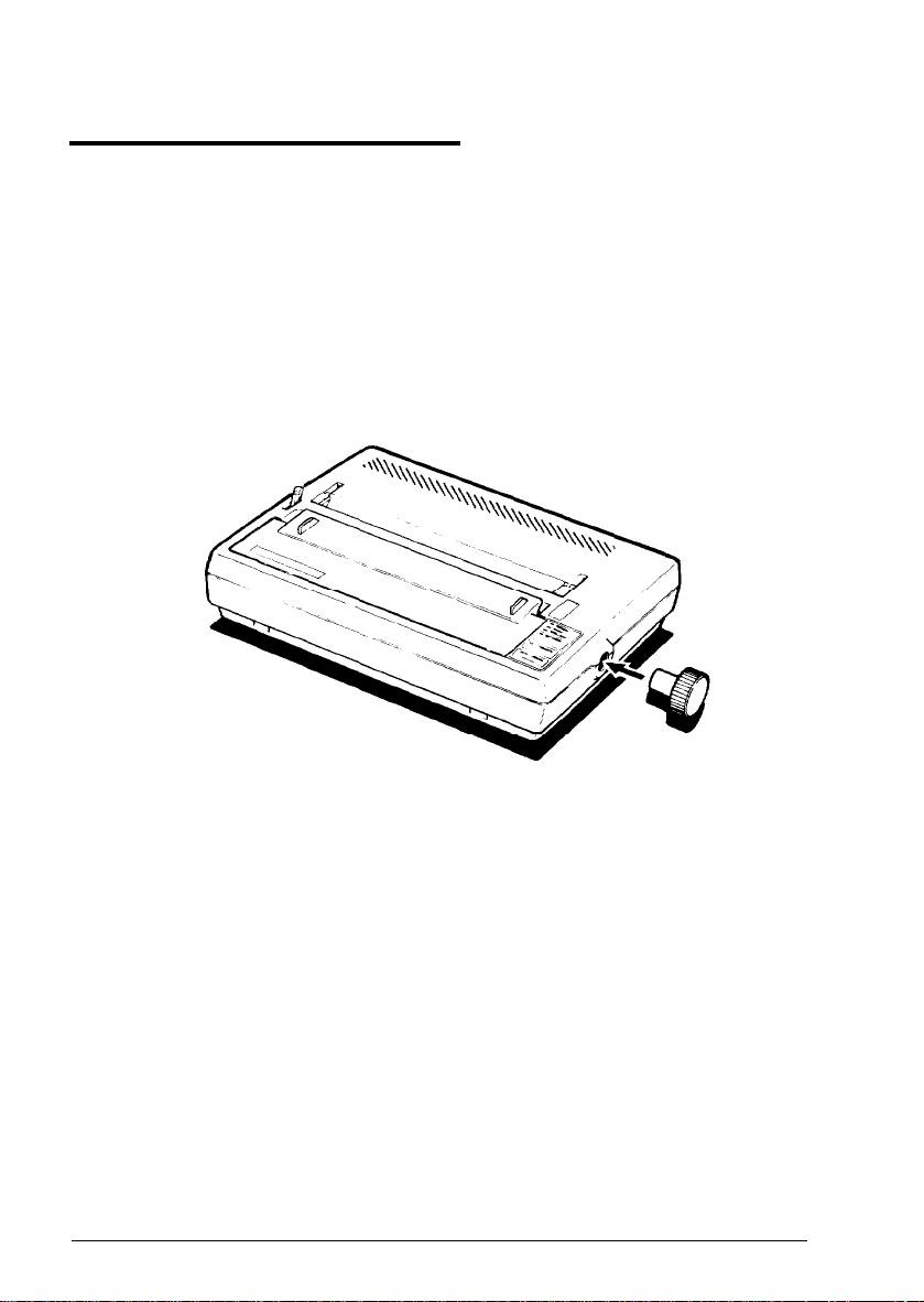
Installing the Paper Feed Knob
Now that you have decided where to locate your printer, the first step in
setting it up is installing the paper feed knob. Follow these steps:
1.
Locate the paper feed knob, which is packed into an indentation in
the white foam material.
2.
Insert the knob into the hole on the right side of the printer, as
shown below. Gently rotate the knob until it fits over the shaft.
3.
Push the knob in until it is flush with the printer case.
Setting Up 1-5
Page 13
Installing and Replacing the Ribbon
The printer uses a continuous-loop, inked fabric ribbon. It is enclosed in
a cartridge that makes ribbon installation and replacement a clean and
easy job.
To install the ribbon, follow these steps:
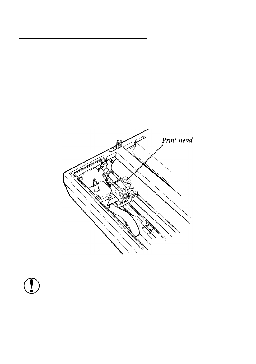
1.
Remove the lid at the front of the printer by lifting the handles.
Removing the lid enables you to see the print head, which is shown
below.
1-6
CAUTION:
head because moving the print head when the power is on
may damage your printer. Also, if you’ve been using your
printer, be careful not to touch the print head because it
becomes hot during use. Let it cool for a few minutes.
Setting Up
The power must be off when you move the print
Page 14
installing and Replacing the Ribbon
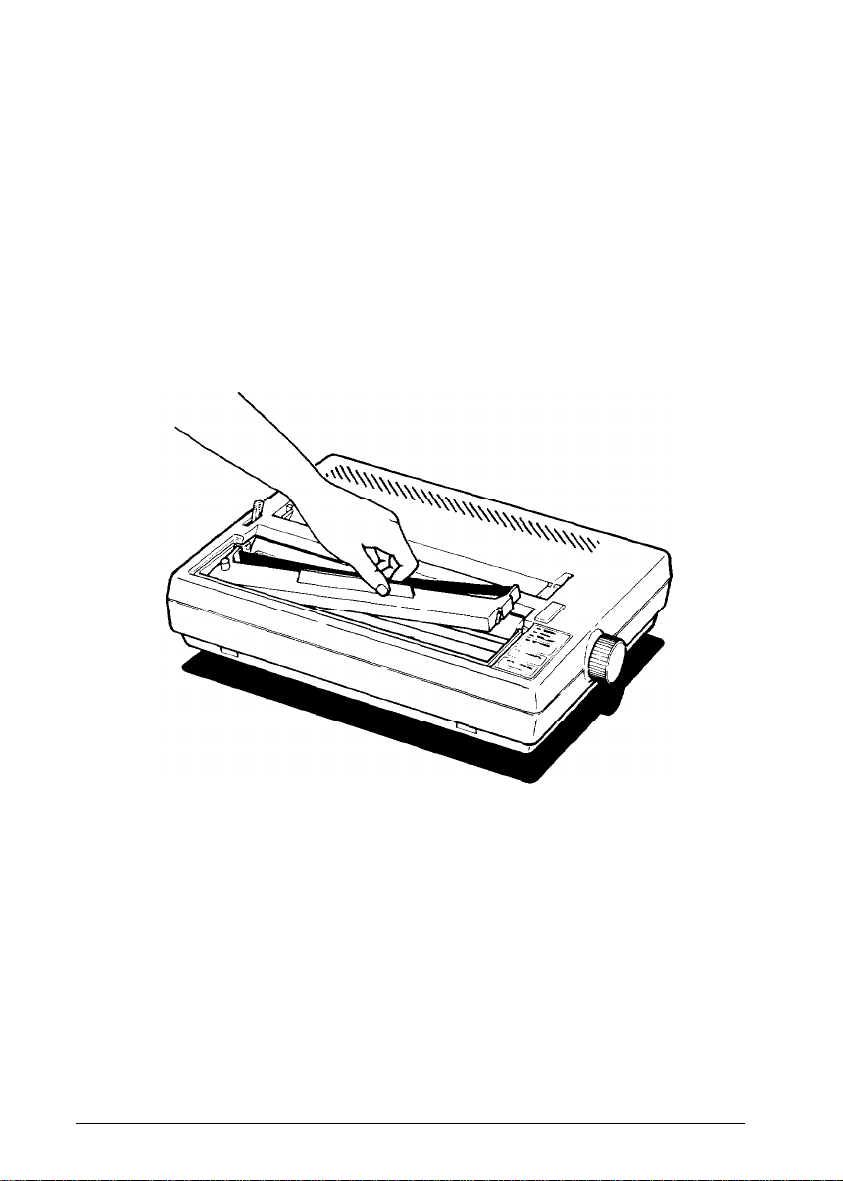
2.
Move the print head by hand to the center of the printer so that the
other parts of the printer will not get in your way.
3. Grasp the ribbon cartridge by its handle and hold the cartridge so
that the exposed strip of ribbon is facing away from you.
4.
Insert the cartridge by placing the black hooks on each side of the
cartridge into the slots located inside the printer in the right and left
front corners. Push down until the cartridge snaps into place. (See
the illustration below.)
Setting Up
1-7
Page 15
installing and
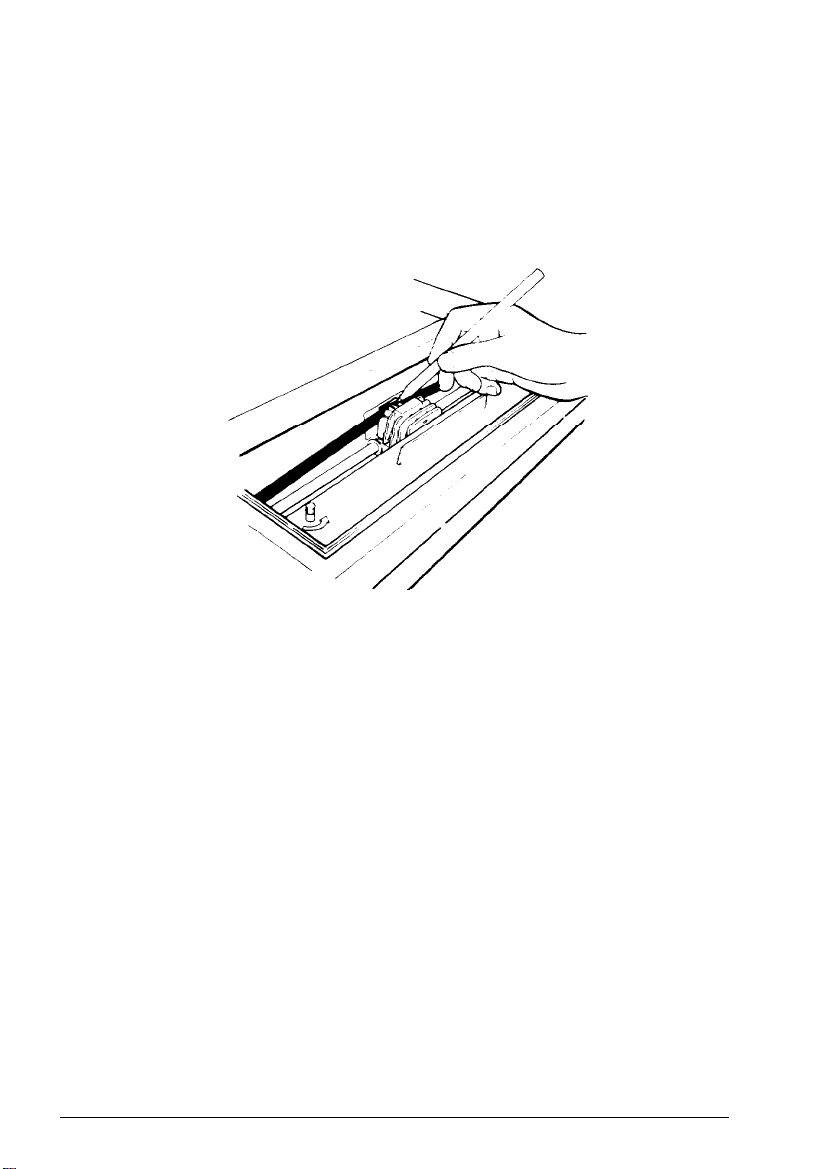
5.
Turn the knob on the cartridge in the direction of the arrow to
Replacing the Ribbon
tighten the ribbon. As you turn the knob, see that the ribbon slips
down into its proper place between the print head and the ribbon
guide. You may want to use a pen to direct the ribbon, as shown in
the next illustration.
6. Replace the front lid by inserting its legs into the slots near the front
comers of the printer. Lay the lid down and press to snap it into
place.
Replacing the ribbon
When your printing becomes light and you need to replace the ribbon,
follow these steps:
1.
Remove the front lid.
2. Grasp the ribbon cartridge handle and pull out the cartridge.
3. Follow the ribbon installation instructions above to insert the new
ribbon cartridge.
1-8
Setting Up
Page 16

Using Continuous-feed Paper
The following section covers use of continuous-feed paper with your
tractor unit. If you plan to use single-sheet paper, skip to the
“Removing the tractor unit” section on page
The tractor unit for the printer allows you to use paper with pin feed
holes along the sides (continuous-feed paper). You can adjust the tractor
unit to accommodate widths of paper ranging from 4 to 10 inches,
including the pin feed holes.
Installing the tractor unit
You need to install the tractor unit each time you wish to load
continuous-feed paper after using single-sheet paper, which can be loaded
only when the tractor unit is removed.
Since your printer comes with the tractor unit installed, simply install the
paper rest by fitting it into the slots along the top edge of the back of the
printer and snapping it into place. (See the bottom illustration on the
following page.) Then see the instructions later in this chapter for loading
continuous-feed paper.
To install the tractor unit, follow these steps:
1-17.
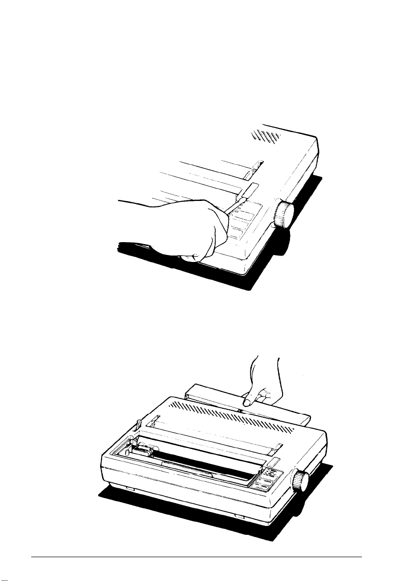
1.
If the paper guide is installed, remove it by tipping it toward you and
pulling it out.
Setting Up
1-9
Page 17
Using Continuous-feed Paper
2.
Pop out the tractor unit slot cover, which is located above the
indicator lights. It may help to use the flat edge of a screwdriver, as
shown on the next page. Store the cover in a safe place while you use
the tractor unit, and replace it when you remove the tractor unit.
3.
Fit the paper rest into the slots along the top edge of the back of the
printer and snap it into place, as shown below.
1-10 Setting Up
Page 18
Using Continuous-feed Paper
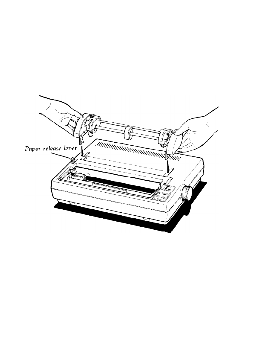
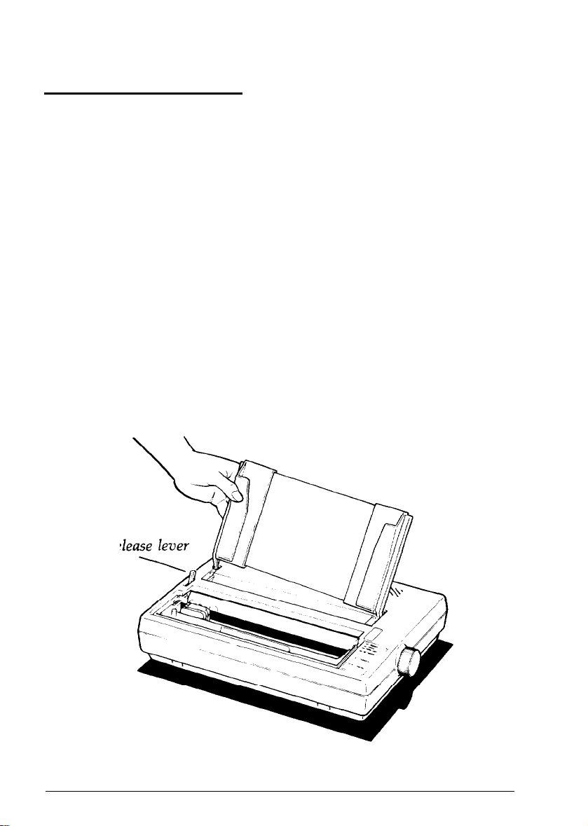
Pull the paper release lever forward. (See the illustration below.) The
4.
double-arrow icon in
front
of the lever marks the position the lever
should be in for using continuous-feed paper (or for releasing paper).
Now install the tractor unit. First, hold the unit so that its black legs
5.
are facing downward, as shown below.
Setting Up
1-11
Page 19
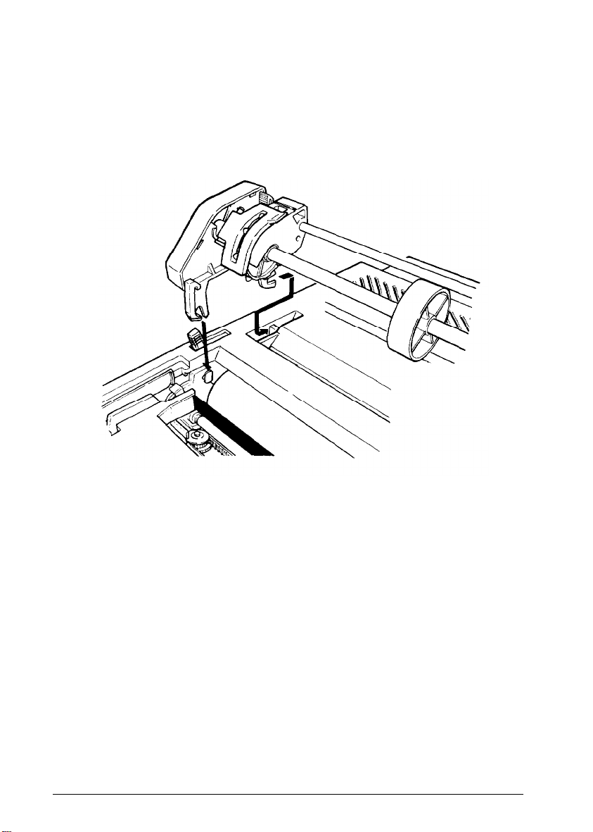
Using Continuous-feed Paper
In each tractor slot, located at each side of the paper slot, is a peg
6.
that fits into the notch on each of the rear tractor legs. Tilt the
tractor back so that the rear notches fit over these pegs, as shown
below.
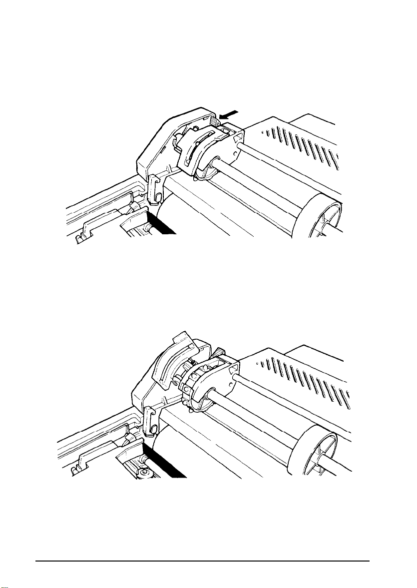
Then tilt the unit forward until the front legs snap into place.
7.
Loading continuous-feed paper
Once the tractor unit is installed, load continuous-feed paper as follows:
Make sure that the printer is turned off.
1.
Remove the front lid of the printer.
2.
Move the print head to the center of the printer. Remember, the
3.
printer must be turned off whenever you move the print head. Also,
if you’ve been using the printer, the print head may be hot. Be
careful not to touch it unless you let it cool for a few minutes.
1-12 Setting Up
Page 20
Using Continuous-feed Paper
4. Using the illustration below as a guide, pull the locking levers on
each side of the pin feed holders forward so you can move the pin
feed holders.
5.
Place the left holder approximately 3/4 of an inch from the far left
position and then push the locking lever back to fasten that holder
into place. Leave the other holder unlocked.
6.
Open the pin feed
covers
as shown below.
7.
Feed the paper into the paper slot. Push and maneuver the paper
through the slot until it comes up between the ribbon guide and the
platen (the black roller).
Setting Up
1-13
Page 21
Using Continuous-feed Paper
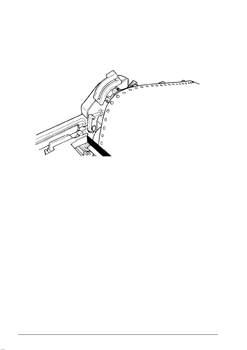
8. Pull the paper up until the top is above the pin feed holders. Fit the
holes along the left edge of the paper over the pins in the left holder,
as shown below, and close the pin feed cover.
9. Fit the right side of the paper into the right holder, moving the holder
as needed to match the width of the paper. Close the second pin feed
cover.
10. Make sure that the paper has no dips or wrinkles, then push the
locking lever back to lock the right holder in place.
Installing the paper guide
Install the paper guide, which is used here as a paper separator, as
described below. Note that the guide is installed in one of two different
positions depending on the type of paper you use. It lies flat when you
use continuous-feed paper, as described here, and sits upright for loading
single-sheet paper.
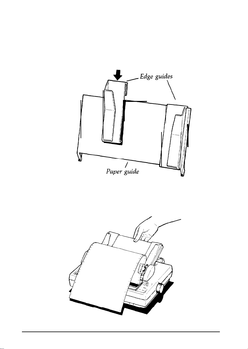
1.
If the edge guides are not yet in place, install them by hooking the
tab on the back of each guide over the top of the paper guide, as
shown in the illustration on the next page. Snap the bottom of each
guide into place.
1-14
Setting Up
Page 22
Using
Continuous-feed
Paper
For continuous-feed paper, move the edge guides to the far right and
left positions on the paper guide. You won’t be inserting paper
through the edge guides unless you use single-sheet paper.
2.
Insert the legs of the paper guide into the slots behind the tractor unit,
keeping the guide tilted backward as you do so. (See the illustration
below .)
Setting Up
1-15
Page 23
Using Continuous-feed Paper
When the legs are in the slots, lean the guide all the way back. The
3.
guide should rest above the paper entering the printer, separating it
from paper exiting the printer.
Setting top of form
Now you are ready to set the top of form position. Follow these steps:
Turn the paper feed knob to advance the paper until the
1.
perforation between pages is just below the top of the ribbon.
Now replace the front lid.
2.
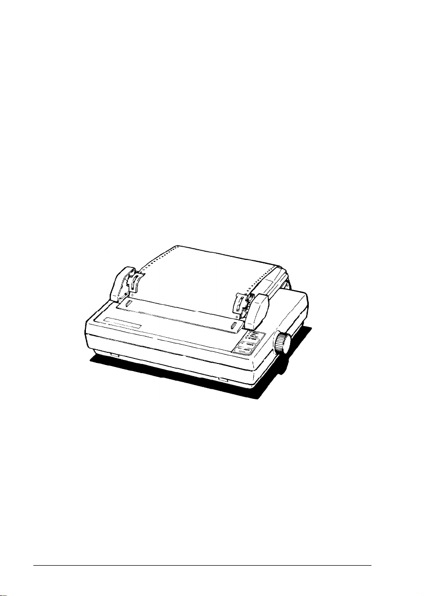
Your printer should now be set up as shown below.
When you turn on your printer, it remembers this top of form setting
and uses it when any program tells it to move to the top of the next
page. If you later find that your word processing or other application
program prints too high or too low on the page or is printing on the
perforations, check to see that your top of form setting is correct.
1-16
Setting Up
Page 24

Using Continuous-feed Paper
Once you have set the top of form, each time you finish printing a
document, push the
then push the
ON/OFF LINE
FORM FEED
button to put the printer off-line and
button once to advance the paper one sheet.
This enables you to tear off your just-printed pages and leave the paper
in the correct position to begin the next document.
Note:
Make sure that the front lid is in place whenever you print.
(Always snap the lid shut when replacing the lid.) The front lid
doubles as a paper bail, holding the paper against the platen.
Removing the tractor unit
It is necessary to remove the tractor unit before you use single-sheet
paper. To remove the unit, follow these steps:
1.
Remove the front lid.
2.
Open the pin feed covers and pull the paper off the pins. Then lay
the paper over the front of the printer so you can reach the tractor
feed unit.
3.
Grasp both sides of the tractor unit and gently lift up the front end.
This action unsnaps the front legs of the tractor unit and enables you
to lift off the unit.
4.
Pull the paper guide toward you until it settles into an upright
position for single-sheet paper.
5.
Make sure that the paper release lever is forward, and remove the
paper.
6.
Replace the front lid.
Setting Up
1-17
Page 25
Using Single-sheet Paper
Before you load single-sheet paper, you must prepare the printer by
installing the paper guide in an upright position. If the tractor unit is
installed, remove it by following the instructions above. After following
those instructions, you can skip the following section on paper guide
installation, except for step 3 on aligning the left edge guide.
Installing the paper guide
Install the paper guide as follows:
1.
If you have not already done so, install the edge guides on the paper
guide by hooking the tab on the back of each guide over the top of
the paper guide, as shown on page l-15. Snap the bottom of each
edge guide into place.
2.
Hold the paper guide upright and insert the legs of the guide into the
slots on either side of the printer, as shown below.
l-18
Paper
re
Setting Up
Page 26
Using Single-sheet Paper
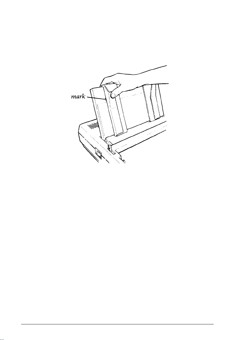
3.
Align the left side of the left edge guide with
the
guide mark
on the
paper guide as shown below. You may later wish to adjust this edge
guide depending on the margin setting in your application program.
Guide
Automatic paper loading
Now you are ready to load single-sheet paper using the printer’s auto
load feature.
To load paper automatically, just follow these steps:
1.
Push back the paper release lever. (See the illustration on
the
previous page.) The single-arrow icon behind the lever marks the
position the lever should be in for loading single-sheet paper.
Turn on the printer.
2.
Make sure that the ON LINE indicator is off. If it is not off, press
3.
the panel labeled
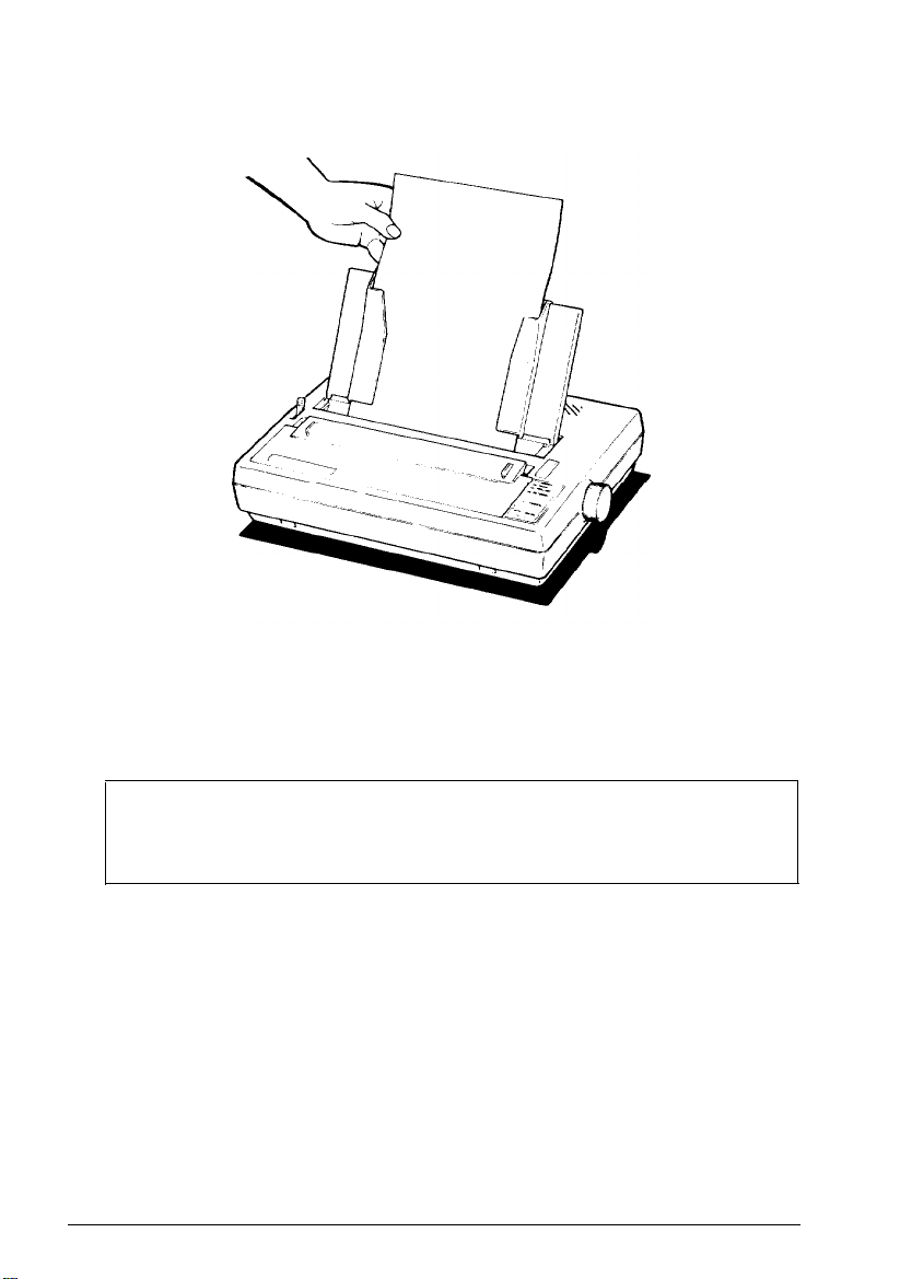
Adjust the right edge guide to fit the size of the paper.
4.
Slide the paper down through the edge guides until it meets
5.
resistance. Press down on the paper a bit more to make sure
ON/OFF LINE.
that
it is
firmly in place, as shown in the following illustration.
Setting
Up
1-19
Page 27
Using Single-sheet
6.
Press and release
DRAFT/LINE FEED
top of
the
Paper
page.
the AUTO LOAD
button (the same button as the
button). The paper is automatically loaded to the
7.
Push the
ON/OFF LINE
button so that the printer is ready to print.
Note: Make sure the front lid is in place whenever you print.
(Always snap the lid shut when replacing
the
lid.) The front lid
doubles as a paper bail, holding the paper against the platen.
8.
If the paper is crooked and needs to be reloaded, pull the paper
release lever forward, pull out the paper, push the lever back,
turn the printer off, and reload by beginning again at step 1 in the
“Automatic paper loading” section above. If the paper just requires
minor adjustment, then pull the paper release lever forward, open
the front lid, adjust the paper, and push the lever back. Then
close the front lid.
l-20
Setting Up
Page 28

Using Single-sheet Paper
Reloading during printing
When you print a document more than one page long using single-sheet
paper, there are two ways your software can enable you to load a new
sheet at the end of a page:
l
If your software sends characters in a continuous stream, the printer
stops printing when it reaches the bottom of the paper. When this
happens, the
l
If your software handles printing page by page, it probably stops
ON
LINE light goes off automatically.
sending characters at the end of a page and prompts you to insert
more paper’. In this case, the
the first thing you should do is press the
ON LINE
light may remain on. If it does,
ON/OFF LINE
button once to
turn it off.
Once the
ON LINE
light is off, remove the sheet that has just been printed
and load a new sheet in the same way as before.
Printing multi-part forms and copies
If you wish to print multi-part forms or carbon copies, use no more than
three sheets or parts at a time, with a total thickness of no more than
0.01
inches. The factory setting for the paper thickness lever, located
inside the front lid on the left side, accommodates both single sheets and
multiple forms. There is no need to adjust the lever.
Setting Up
1-21
Page 29
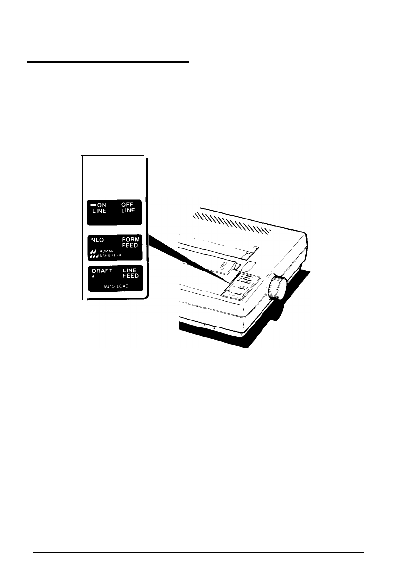
Operating the Control Panel
Now that your paper is loaded, it is time to see what the indicators and
buttons on the control panel do. First, see that the power switch on the
left side of the printer is on. Then take a look at the control panel. (See
the following illustration.)
- POWER
- READY
- PAPER OUT
There are four indicator lights and three buttons on the control panel.
Indicator lights
The indicator lights give you information on the printer’s status:
l
The
POWER
l
The
READY
light glows green when the power is on.
light glows green when the printer is ready to receive
data. This light flickers somewhat during printing.
1-22
Setting Up
Page 30

Operating the Control Panel
l
The
PAPER OUT
light glows red to indicate that the printer is out of
paper or the paper is loaded incorrectly. If you try to print and the
printer does not respond, check to see if this light is on.
l
The
(The
ON LINE
ON LINE
light glows green when the printer can receive data.
light is located on the
ON/OFF LINE
button.)
Buttons
The buttons, or touch-sensitive panels, have several functions, including
selecting draft or NLQ (Near Letter Quality) printing. Draft is good for
quick printing of ordinary work, and NLQ has more fully-formed
characters for final copies or special purposes. NLQ is available in both
Roman and Sans Serif fonts.
The printout below shows the differences among draft, NLQ Roman,
and NLQ Sans Serif so that you can compare the different styles and
densities:
Draft printing
is extremely fast.
NLQ Roman is clear and typewriter-like.
NLQ Sans Serif is crisp and distinctive.
See Chapter 3 for more information on these modes and ways to select
them.
l
ON/OFF LINE.
off line status.
l
NLQ/FORM FEED.
advances continuous-feed paper to the top of the next form or ejects
a single sheet. When the printer is on line, pressing this button selects
NLQ (Near Letter Quality) printing.
Pressing the
the NLQ font between Roman and Sans Serif. When NLQ Roman is
selected, the beeper sounds twice. When NLQ Sans Serif is selected,
the beeper sounds three times.
This button switches the printer between on line and
When the printer is off line, pressing this button
FORM FEED
button when the printer is
ON LINE
Setting Up
alternates
l-23
Page 31

Operating the Control Panel
.
DRAFT/LINE FEED. When the
printer is off line, pressing this button
advances the paper one line. When the printer is on line, pressing this
button
selects draft printing. When you select draft printing the
beeper sounds once. This button also controls the auto load feature.
The control panel buttons also control the SelecType feature. This
feature enables you to select among emphasized, double-strike,
condensed, and elite typestyles. See Chapter 2 for more information.
Performing the self test
Now you’ll see your printer print something even though it’s not yet
connected to a computer. Follow these steps:
1.
Make sure that your printer has paper in it.
2.
Turn the power switch off, then hold down
the DRAFT
button on the
control panel while you turn the power back on. The printer begins
printing letters, numbers, and other characters that are stored in its
ROM (Read Only Memory) in draft mode. (If DIP switch
been turned on, the test will be performed in NLQ mode, as in step
l-5
has
4
below .)
3.
When printing starts, you can release
the DRAFT
button; the printing
continues until you turn the printer off or until the printer runs out
of paper.
4.
To perform the same test in the NLQ mode, load another sheet of
paper. Turn the printer off, then turn it back on while holding down
the NLQ button. Sans Serif and Roman fonts alternate for this test.
Partial results of both tests are shown in the following samples.
l-24
Setting Up
Page 32

DRAFT
Operating the Control Panel
’ ()*+,-./
0123456789: ;<=>?@
ABCDEFGHIJLMNO
( ) *+,-./0123456789: ; <=>?@ABCDEFGHIJKLMNOP
)*+,-.
*+,-./
+,-.
/0123456789 : ; <=>?@
02356789:;<=>?@
/0123456789: ; <=>?@
,-- . /0123456789 : ; <=>?@
,-./0123456789:;,<=>
,/0123456789:;<=>?
/0123456789: ; <=>?@
NLQ
' ()*+,-.
10123456789:
?@ABCDEFGHIJKLMNOPQRSTU
@ABCDEFGHIJKLMNOPQRSTUV
ABCDEFGHIJKLMNOPQRSTUVW
O*+,-./0123456789:;
)*+,-.
*+,-
+
,-./0123456789:,
-./0123456789
./0123456789:;
10123456789:;
/0123456789:;<=>?@ABCDEFGHIJKLMNOPQ
./0123456789:;
*<=>?@ABCDEFGHIJKLMNOPaRS
+,-./0123456789:;
<=>?@ABCDEFGHIJKLMNOPQRST
:;<=>?@ABCDEFGHIJKLMNOPQRSTU
<=>?@ABCDEFGHIJKLMNOPQRSTUV
<=>?@ABCDEFGHIJKLMNOPQRSTUVW
ABCDEFGHIJKLMNOPQ
ABCDEFGHIJKLMNOPQR
ABCDEFGHIJKLMNOPQRS
ABCDEFGJHIJKLMNOPQRST
;<=>?@ABCDEFGHIJKLMNO
<=>?@ABCDEFGHIJKLMNOP
<=>?@ABCDEFGHIJKLMNOPQR
Setting Up
l-25
Page 33

Connecting the Printer to Your Computer
Now that the test pattern has shown that your printer is operational, it’s
time to hook it up to your computer.
Remember
that
computer systems communicate with printers in a variety
of ways. If your computer expects to communicate through a Centronics
parallel interface, all you need is the proper shielded cable. If your
computer requires any other kind of interface, you also need an interface
board.
If you don’t know
manual or your dealer can tell you
what
a Centronics parallel interface is, your computer
what
you need. Then, once you have
plugged your printer cable into your printer and computer, you will
probably never think about interfaces again. (If you do want the
technical specifications, however, you can find them in Chapter 6.)
Follow these steps and see the illustration below to connect your printer
and computer:
1.
Make sure that both your printer and computer are turned off.
2. Plug the appropriate end of your printer cable into the cable
connector of your printer. The plug is shaped so it fits the connector
only one way.
1-26 Setting Up
Page 34

Connecting the Printer to
3. Secure the plug to the printer with the wire clips on each side of the
connector. Press the clips into the metal clasps at each side of the
plug. These clips ensure that your cable will not be loosened or
unplugged accidentally.
4.
If your cable has a grounding wire, fasten it to the grounding screw
below the connector.
5.
Connect the other end of the printer cable to your computer. On
most computers you can easily find the correct connector for the
printer cable, but if you are not sure, consult your computer manual.
Your
Computer
Setting Up
1-27
Page 35

Printer Selection Menus
Most application programs let you specify the type of printer you’re
using so that the program can take full advantage of the printer’s
features. Many programs provide an installation or setup procedure that
presents a list of printers to choose from.
Choosing from a menu
Because the family of Epson printers shares a great many commands,
you can use an application program even if it does not list your printer
on its printer selection menu. Choose from the following list (the printers
are listed in the order of preference):
T-1000/Lx-400
LX-800
FX-86e/FX-850
LX printer
FX printer
Epson printer
Draft printer
Note: If your application program does not list your printer, you may
want to contact the manufacturer to find out whether an update is
available.
A quick test
After setting up your application program, print a sample document to
be sure the program and the printer are communicating properly. If the
document doesn’t print correctly, recheck the program’s printer selection
and installation procedure. If you’re still having trouble printing, consult
Chapter 4.
1-28
Setting Up
Page 36

Chapter 2
SelecType
SelecType Operation
Turning SelecType on
Selecting typestyles
SelecType Tips
.....................................
................................
..............................
................................
2-2
2-2
2-3
2-5
SelecType 2-l
Page 37

SelecType Operation
The printer’s SelecType feature can produce four special typestyles:
This is emphasized printing.
This is in the double-strike mode.
This is condensed printing.
‘This is in the elite mode.
Using SelecType is easy. You turn on SelecType and select a typestyle,
then turn off SelecType and print.
Turning SelecType on
1.
Make sure that the printer is on line.
2.
Hold down the
(See the illustration below.) When you turn on SelecType, a short
beep sounds and the
is in SelecType mode.
ON/OFF LINE
ON LINE
button and press the
FORM FEED
button.
light blinks to indicate that the printer
2-2
SelecType
Page 38

SelecType Operation
Selecting typestyles
In SelecType, each button has a function:
l
ON/OFF LINE
l
FORM FEED
l
LINE FEED
selects typestyles.
sets the styles.
turns SelecType off.
After turning on SelecType, follow these steps to select a typestyle:
1.
Find the typestyle you want in the table below. All of the typestyles
listed in the table are available for draft mode. If you are in NLQ
mode, only emphasized and elite are available.
Mode
1
2
3
4
2.
Press the
Emphasized ABCDEFGHIJKLMnopqrstuvwxyz
Double-strike
Condensed
Elite
ON/OFF LINE
ABCDEFGHIJKLMnopqrstuvwxyz
ABCDEFGHIJKLMnopqrstuvwxyz
ABCDEFGHIJKLMnopqrstuvwxyz
button the number of times indicated in the
Typestyle
mode column. Be sure that the printer beeps each time you press the
ON/OFF LINE
3.
Press
4.
Press
the FORM FEED
the LINE FEED
button.
button to set the typestyle.
button to turn SelecType off. The control panel
returns to its normal functions, but the printer is off line.
5.
Press
the ON/OFF LINE
button, and you are ready to print.
You can combine any of the modes listed in the above table when you
are in draft mode, except for emphasized and condensed. In NLQ, the
two available modes (emphasized and elite) may be combined.
If you wish to combine two modes, follow steps 1 through 3 above, then
return to step 1 and follow the entire sequence (steps 1 through 5). (Do
the same thing to combine three modes, but repeat steps 1 through 3 for
each of the first two modes you enter.) Always select the lowest mode
number first.
SelecType 2-3
Page 39

SelecType Operation
When you press the
ON/OFF LINE
button to select an additional mode,
start counting again where you left off. That is, if you have selected
emphasized and wish to combine that with elite, press the
ON/OFF LINE
button three more times, not four, to select elite. For example, follow
these steps to combine emphasized and elite:
1.
Press the
2.
Press the
3.
Press the
ON/OFF LINE
FORM FEED
ON/OFF LINE
button once to select emphasized.
button.
button three more times to select elite. (The
mode is four, but remember that you have already pressed the
ON/OFF LINE
4.
Press the
5. Press the LINE FEED button.
6.
Press the
button once.)
FORM FEED
ON/OFF LINE
button.
button, and you are ready to print.
Note: Some application programs are designed to control all
typestyle functions. These programs cancel previous typestyle
settings by sending certain printer codes before printing. Because
these codes cancel SelecType settings, you have to use the
program’s print options function instead of SelecType to select
your typestyles. Therefore, if SelecType does not work with a
particular application program, consult its manual on how to
select typestyles.
2-4
SelecType
Page 40

SelecType Tips
Once you have learned the simple technique for controlling print styles
with SelecType, you can use it whenever you wish. You should be aware
of a few points, however.
SelecType is designed to control the printing of an entire file or
document, not an individual line or word.
If you are using the NLQ mode, remember that the following
SelecType modes are not available: double-strike and condensed.
If there are print codes in the document or file you are printing, those
codes will override your SelecType settings. This seldom happens,
since you usually won’t use SelecType with files that have such
codes, but if your printer follows the SelecType instructions for only
part of a document, it may be that print codes in the document are
conflicting with the SelecType modes.
After you turn on a mode with SelecType, it stays in effect until the
printer is turned off or until you send a software command that
overrides it. (In general, software commands override SelecType
settings.) If, for example, you use SelecType to print a document in
emphasized type, anything you print after that will be emphasized
unless you first turn the printer off and back on.
SelecType 2-5
Page 41

SelecType Tips
2-6
SelecType
Page 42

Chapter 3
Printer Features
Quality and Fonts
Print Size and Character Width
Pitches
Double-wide and condensed
Special Effects and Emphasis
Using Different Character Sets
..........................................
...................................
..........................
.......................
........................
........................
3-2
3-3
3-3
3-3
3-5
3-6
Printer Features 3-1
Page 43

Quality and Fonts
The most fundamental changes you can make to printing are in the print
quality and NLQ fonts.
The printer has two levels of print quality: draft and NLQ (Near Letter
Quality). Draft printing is fast, making it ideal for drafts and other
preliminary work. NLQ printing takes a little longer, but it produces
more fully-formed characters for presentation-quality documents.
The printout below shows the differences between draft, NLQ Roman,
and NLQ Sans Serif so that you can compare the different styles and
densities:
Draft printing is extremely fast.
NLQ
Roman is clear and typewriter-like.
NLQ Sans Serif is crisp and distinctive.
The buttons on the control panel give you an easy way of changing the
print quality and NLQ font, but if you prefer to print in NLQ Roman
most of the time, you can select it with a DIP switch (see Chapter 5). You
can also choose the print quality and NLQ font with software
commands.
3-2
Printer Features
Page 44

Print Size and Character Width
To add greater variety to your documents, the printer has two pitches
and condensed printing. All can be selected either with SelecType or a
software command, and software commands also offer another option:
double-wide.
Pitches
The two pitches are pica and elite. Pica is 10 characters per inch (cpi) and
elite is
12
cpi. The printout below shows the difference between the two.
Pica:
ABCDEFGHIJKLMnopqrstuvwxyz
Elite: ABCDEFGHIJKLMNopqrstuvwxyz
Double-wide and condensed
In addition to the basic pitches, the printer offers two other modes that
change the size of your printing. These modes are double-wide and
condensed.
The double-wide mode doubles the width of any size of characters. This
mode is useful for such purposes as emphasizing headings in reports and
making displays, but it is usually not suitable for large amounts of text.
Double-wide
Double
Pica and elite are reduced to about
condensed mode. This mode is particularly useful for printing wide
spreadsheets because condensed elite allows you up to
an 8-inch line.
--wide elite
60%
pica
of their normal width with the
160
characters on
Printer Features 3-3
Page 45

Print Size and Character Width
Condensed can be selected with
SelecType,
by setting a DIP
switch (see
Chapter 5), or with a software command. Even if you turn condensed on
with the DIP switch, you can still turn it off with SelecType or the
software command.
Condensed pica
Condensed
elite gives you even mare.
gives
more characters on a line.
Widening or narrowing the characters also widens or narrows the spaces
between
words and
letters. Because word processors usually create a left
margin by printing spaces, you may need to change the left margin and
the number of characters on a line to keep the margins correct if you
change widths. For example, a left margin of five pica characters is the
same as one of six elite characters.
3-4
Printer Features
Page 46

Special Effects and Emphasis
The printer offers two ways of emphasizing parts of your text and also
allows you to use underlining, superscripts, and subscripts. Most of these
features can be controlled only by software commands, but many
application programs can produce them if they are properly installed.
Emphasized and double-strike modes, both of which can be chosen with
SelecType, slow the printer down slightly to produce bolder text. In
emphasized mode, the printer prints each character twice as the print
head moves across the paper, with the second pass slightly to the right of
the first. This produces darker, more fully-formed characters.
In double-strike mode, the printer prints each line twice, with the second
pass slightly below the first. This makes the characters bolder. While
NLQ is in use, however, double-strike is ignored because NLQ characters
are already formed by two passes of the print head.
This is normal NLQ printing.
This is emphasized NLQ printing.
Superscripts and subscripts are valuable for such purposes as printing
footnote numbers or parts of mathematical formulas, and the underline
mode provides an automatic way of underlining fully any piece of text.
It underlines spaces, subscripts, and superscripts without a break.
The example below shows underlining combined with subscripts in a
mathematical formula.
average = (a1 + a2 + . . . . . + an)
n
Printer Features 3-5
Page 47

Using Different Character Sets
The printer incorporates a special character set: Epson Character
Graphics. This set allows you to take, advantage of the power of the
Epson commands and still print out the character graphics used by IBM
and IBM-compatible computers and by much commercial software. For
example, if your word processor can include the characters to draw
boxes and shade areas, you can produce some very professional effects.
You can select the Epson Character Graphics set with your software or
by setting DIP switch l-3 ON. For most applications it is best to use the
DIP switch instead of the software command because the character
graphics are then available as soon as you turn the printer on.
The other important change you can make to the standard character set
is to change some characters for ones commonly used in other
languages-chiefly European and Scandinavian-such as accented
characters and symbols. Eight international character sets can be selected
by setting DIP switches 1-6 to 1-8: USA, French, German, UK, Danish,
Swedish, Italian, and Spanish. See Chapter 5 for the DIP switch settings.
These eight, and five more, can also be selected by a software
command. The additional character sets are the following:
Norwegian, a second Danish set, Japanese, a second Spanish set, and
Latin American. The table on the next page shows all of these
characters.
3-6
Printer Features
Page 48

Using Different Character Sets
35 36 64 91 92 93 94 96 123 124 125 126
0
USA
1
France
2
Germany
3
UK
4
Denmark
5
Sweden
6
Italy
7 Spain I
8
Japan
9 Norway
10 Denmark II
11 Spain II
13 Latin America
I
Also, all text characters can be printed in italics. You can use this
typestyle for special emphasis or as an alternative typeface.
Italics give emphasis to words.
They are an attractive alternative style.
Printer Features 3-7
Page 49

Using Different Character Sets
3-8
Printer Features
Page 50

Chapter 4
Troubleshooting and Maintenance
Problem/Solution Summary
Beeper Error Warnings
Cleaning the Printer
Transporting the Printer
...............................
.................................
..............................
..........................
4-2
4-4
4-5
4-6
Troubleshooting and Maintenance
4-l
Page 51

Problem/Solution Summary
Problem
Printer does not print
Printing is patchy,
faint, uneven, or
intermittent
Solution
Make sure that the printer is turned on and is
on line. Both the
should be on.
Make sure that the printer and computer are
connected. Be certain you are using the
correct cable and that it is firmly plugged in at
both ends.
Turn the printer off and on again to reset it.
While the printer is turned off, make sure the
paper is loaded correctly.
If the printer still does not print, try the self
test procedure described in Chapter 1. If the
self test works correctly, the printer is all right
and the problem lies elsewhere. If the self test
doesn’t work, take the printer to a qualified
service center.
Check that the ribbon is seated correctly.
Check that the ribbon moves freely in the
cartridge.
POWER
and
ON LINE
lights
4-2
If you have been using the ribbon for a long
time or for a large amount of printing, it may
need to be replaced.
It is also possible for the print head to wear
out if the printer is used frequently and for
long periods at a time. Contact an Epson
dealer if you think the print head needs to be
replaced.
Troubleshooting and Maintenance
Page 52

Problem/Solution Summary
Problem
All the text is printed
on the same fine or
text is printed with an
extra blank line
between
Some
of the
characters printed do
not match
file
Can’t get condensed
print
those in the
Solution
This can usually be corrected by changing the
setting of DIP switch
solve the problem, you may need a different
cable.
If they are international characters, check the
settings of DIP switches 1-6 to l-8. If they are
graphics characters, see that your software is
correctly installed and that you have correctly
set DIP switch
l-3.
See that the printer cable is securely plugged
in.
Cancel emphasized mode; it has priority over
condensed.
Cancel NLQ mode; it has priority over
condensed.
2-4.
If that does not
Troubleshooting and Maintenance
4-3
Page 53

Beeper Error Warnings
When the printer’s beeper sounds, it usually indicates that the printer is
out of paper. If the printer beeps and stops printing when it is not out of
paper, turn the printer off and check to see that the paper is loaded
correctly. If the paper is loaded correctly, turn the printer back on and
try to print again. If the printer beeps and does not print again, take it to
a qualified service person.
4-4
Troubleshooting and Maintenance
Page 54

Cleaning the Printer
To keep your printer running at its best, you should clean it thoroughly
several times a year. Follow the steps below:
1.
Make sure the printer is turned off. Then remove the paper guide.
2.
Using a soft brush, carefully remove all dust and dirt.
3.
If the outer case or paper guide is dirty or dusty, clean it with a soft,
clean cloth dampened with a mild detergent solution. Keep the front
lid in place to prevent water from getting inside the printer.
WARNINGS:
0
Never use alcohols or thinners to clean the printer; these
chemicals can damage the components as well as the
case.
.
Be careful not to get water on the printer mechanism or
electronic components.
l
Do not use a hard or abrasive brush.
.
Do not spray the inside of the printer with lubricants;
unsuitable oils can damage the mechanism. Contact a
qualified service person if you think the printer needs
lubrication.
Troubleshooting
and Maintenance
4-5
Page 55

Transporting the Printer
Before you transport your printer some distance, carefully repack it in
the original box and packing materials as described in the following
instructions:
1.
Make sure the printer is turned off. Then remove the paper guide and
front lid.
WARNING:
cable from the AC outlet.
2.
Unplug the power cable from the electrical outlet. Coil the cable and
tie it. Then disconnect the interface cable from the printer and
computer.
3. Remove the ribbon cartridge and paper feed knob.
4. Replace the packing materials and put the printer in its box.
Turn the printer off before unplugging the power
4-6
Troubleshooting and Maintenance
Page 56

Chapter 5
Defaults and DIP Switches
Default and Initialization Settings
DIP Switch Settings
International Character Sets
.................................
......................
..........................
5-2
5-3
5-5
Defaults and DIP Switches
5-l
Page 57

Default and Initialization Settings
The printer can be initialized (returned to a fixed set of conditions) in
three different ways: when it is turned on, when it receives an INIT
signal at the parallel interface (pin 31 becomes low), and when it receives
the ESC @ command.
The following conditions always occur when the printer is initialized:
The print head returns to the home position.
Interface signals are reset, and the printer is put on line.
The current print line is cleared.
Margins and vertical tab settings are cleared, line spacing is set to
l/6-inch, horizontal tabs are set at every eighth position and vertical
tab channel 0 is selected.
The page length and skip over perforation are set according to DIP
switches 2-1 and 2-3, and the top of form position is set to the
current line.
The ROM characters are selected, and the character table and
international character set are reset according to DIP switches 1-3
and
l-6
to
l-8.
In addition, when the printer is initialized by turning on the power or by
an INIT signal, the data buffer is cleared of all text.
ESC @ resets the typestyle to the current SelecType settings, but the
other two methods reset the typestyle according to the DIP switches.
Also, ESC @ does not check whether any DIP switches have been
altered since the printer was turned on; instead, it uses the old settings.
5-2
Defaults and DIP Switches
Page 58

DIP Switch Settings
The printer has twelve DIP switches which allow you to change many of
the printer’s settings to suit your individual needs. The DIP switches are
in two groups, mounted on the back panel, as shown below.
DIP switch l-1 is the switch at the far left side, and the one at the far
right is DIP switch
pointed object such as a small screwdriver or the cap of a ballpoint pen.
2-4.
You can easily reset the switches with a thin,
Note: When you change a DIP switch setting, turn off the power, reset
the switch or switches, then turn on the power again. The printer
checks and recognizes new settings only at the time the power is
turned on.
Defaults and DIP Switches
5-3
Page 59

DIP Switch Settings
The tables below describe the DIP switch functions.
DIP Switch 1
Switch
number
1-1
1-2
1-3
1-4
1-5
1-6
1-7
1-8
Function
Select condensed or normal characters
Select slashed or unslashed zero
Select character table
Paper-out detection Inactive
Select print quality
Select international character set
DIP Switch 2
Add line feed after carnage return
Note: The factory setting for all switches except l-6. l-7. and 1-8 is OFF
Action
when ON
Condensed
0
Graphics
NLQ
See table on page 5-5
Action
when OFF
Normal
0
Italics
Active
Draft
5-4
Defaults and DIP Switches
Page 60

International Character Sets
Thirteen international character sets are available. Eight of these are
selected by DIP switches
Norway, Denmark II, Spain II and Latin America) can be selected with
the ESC R command, which is described in the Command Summary
(Chapter 7). For the characters available in each character set, see
Chapter 3.
The DIP switch settings to select the different character sets are shown
below.
1-6
to 1-8, and the remaining five (Japan,
Character set
USA
French
German
UK
Danish
Swedish
Italian
Spanish
DIP switch settings
l-6
ON
ON
ON
ON
OFF
OFF
OFF
OFF
1-7
ON ON
ON
0FF ON
OFF OFF
ON ON
ON
OFF ON
OFF OFF
l-8
OFF
OFF
Defaults and DIP Switches
5-5
Page 61

Chapter 6
Technical Specifications
Printing . . . . . . . . . . . . . . . . . . . . . . . . . . . . . . . . . . . . . . . . . . .
Paper . . . . . . . . . . . . . . . . . . . . . . . . . . . . . . . . . . . . . . . . . . . . .
Mechanical . . . . . . . . . . . . . . . . . . . . . . . . . . . . . . . . . . . . . . . .
Electrical
Environment
Parallel Interface
Data Transfer Sequence
..........................................
.......................................
....................................
..............................
6-2
6-2
6-3
6-3
6-4
6-5
6-7
Technical Specifications
6-l
Page 62

Technical Specifications
Printing
Printing method:
Printing speed:
Printing direction:
Character sizes:
Line spacing:
Impact dot matrix
180 characters per second in draft
elite. 150 characters per second in
draft pica. 25 characters per second
in NLQ pica
Bidirectional logic-seeking for text
printing. Unidirectional for graphics
and by software command for text
All except superscript and subscript
are 3.1 mm high. The widths and
characters per inch (cpi) are given
below:
Mode
Pica
Elite
Condensed Pica
Condensed Elite
l/6-inch, or programmable in
increments of 1/216th of an inch
Width (mm) CPI
2.1
1.5
1.05 17
1.05 20
10
12
Paper
Number of copies:
Paper width:
6-2
Technical Specifications
One original plus two copies; total
thickness not to exceed 0.01 in.
(0.25
mm)
Continuous feed: 4 to 10 in. Single-
sheet: 7.15 to 8.5 in.
Page 63

Mechanical
Technical Specifications
Ribbon:
MCBF:
MTBF:
Print head life:
Dimensions and Weight:
Electrical
Voltage:
Power consumption:
Frequency:
Cartridge, black #8750
Life expectancy (in characters, at
dots/character): 3 million
3 million lines (excluding the print
head)
4,000 hours
200 million strokes per wire
Height (excluding tractor):
Width (with paper feed knob): 15.7 in.
Depth:
Weight (including tractor): 11.2 lbs.
120 VAC ± 10% (120 V model)
220 VAC ± 10% (220 V model)
240 VAC ± 10% (240 V model)
70 VA maximum
49.5 Hz - 60.5 Hz
14
3.5 in.
12.1 in.
Insulation resistance:
Dielectric strength:
10 Mohms between AC power line
and chassis
Can withstand 1 kV rms applied
between AC line and chassis for 1
minute, or 1.20 kV rms for 1 second
Technical Specifications 6-3
Page 64

Technical Specifications
Environment
Temperature:
Humidity:
Shock:
Vibration:
Operation: 41° F to 95º F (5 C° to
35 C°)
Storage:
to 60 Co)
Operation: 10% to 80% without
condensation
Storage: 5% to 85% without
condensation
Operation: Up to 1 G within 1 ms
Storage: Up to 2 G within 1 ms
Operation: Up to 0.25 G at up to
55 Hz
Storage: Up to 0.5 G at up to 55 Hz
-22” F to 149° F (-30 Cº
6-4
Technical Specifications
Page 65

Technical Specifications
Parallel Interface
Connector pin assignments and a description of respective interface
signals are shown below and on the following page.
Signal Return
Pin Pin
1
2
3 21
4
5
6
7
8
9
10
11
12
13
14
15 - NC
19
20
22 DATA 3
23
24 DATA 5 IN
25
26
27 DATA 8
28
29 BUSY OUT
30 PE
Signal
STROBE IN
DATA 1 IN
DATA 2 IN
DATA 4 IN
DATA 6
DATA 7 IN
ACKNLG
AUTO
FEED XT
Direction Description
STROBE pulse to read data in. Pulse
width must be more than 0.5 µs at the
receiving terminal.
These signals represent information of
the 1st to 8th bits of parallel data,
IN
IN
IN
OUT
OUT
IN
-
respectively. Each signal
when data is logical 1 and LOW when it
logical 0.
Approximately, 12 µS pulse.
LOW indicates that data has been
received and that the printer is ready
to accept more data.
A HIGH signal Indicates that the printer
cannot receive data. The signal goes
HIGH in the following cases:
1) During data entry (ea. char. time)
2) During printing
3) When off line
4) During printer-error state.
A HIGH signal indicates that the printer is
out of paper.
Pulled up to +5 V through 3.3 K
resistance.
When this signal is LOW, the paper is
automatically fed 1 line after printing.
(The signal level can be fixed to this by
setting DIP switch 2-4 to ON.)
Unused.
IS
at HIGH level
IS
Technical Specifications 6-5
Page 66

Technical Specifications
16
17
18
31
Return
Pin
-
-
-
-
-
Signal
OV
CHASSIS
GND
NC
GND
INIT
Direction
-
Description
Logic ground level.
Printer's chassis ground, which is isolated
- from the logic ground.
-
-
IN
Unused.
Twisted-pair return signal ground level.
When level becomes LOW, the printer
controller is reset to its power-up state
and the print butter is cleared. This level
Signal
Pin
19-30
is usually HIGH; its pulse width must be
more than 50 µs at the receiving
terminal
32
ERROR
-
OUT
This level becomes LOW when the printer
is in:
1) Paper-end state
2) Off line state
3) Error state.
33
GND
34 NC
35 - -
-
-
Same as for Pins 19 - 30.
Unused.
Pulled up to +5 V through 3.3 K
resistance.
36 - SLCT IN IN The DC1/DC3 code is valid only when
this signal is HIGH. (Internal fixing can
be carried out with DIP switch pin 2-1.
The level of this signal is factory-set to
LOW.)
6-6
Technical Specifications
Page 67

Technical
The column heading “Direction” refers to the direction of signal flow
as viewed from the printer.
“Return” denotes the twisted-pair return, to be connected at signal
ground level. For the interface wiring, be sure to use a twisted-pair
cable for each signal and to complete the connection on the return
side. To prevent noise, these cables should be shielded and connected
to the chassis of the host computer or the printer but not at both
ends.
All interface conditions are based on TTL level. Both the rise and the
fall times of each signal must be less than 0.2 microseconds.
Data transfer must be carried out by observing the ACKNLG or
BUSY signal. (Data transfer to this printer can be carried out only
after receipt of the ACKNLG signal or when the level of the BUSY
signal is LOW.)
Specifications
Data Transfer Sequence
Interface timing
The illustration below shows the timing for the parallel interface.
Technical Specifications 6-7
Page 68

Technical Specifications
Printing enabled/disabled signals and control conditions
The table below shows the relationship between printing being enabled
or disabled, and the on line/off line condition, the printer select signal
(SLCT IN), and the receipt of data on/off control character, DC1/DC3.
ON LINE
(Indicator)
on)
SLCT IN
DC1/DC3 ERROR BUSY
(Data
on/off
ACKNLG Printing
(Disabled/
enabled)
control)
on line
on line High
on line
off line
Low (Sw.
2-1/
interface)
High
High/Low
(no effect)
DC1/DC3 High
(no effect)
DC1
High High/Low
Recv’d
DC3 High
Recv’d
DC1/DC3 Low
(no effect)
High/Low Pulsed ea. Enabled
char.
(normal
cond.)
Pulsed ea. Enabled
char
High/Low Pulsed ea. Disabled*
char.
High
Not
Disabled
generated
*Even though printing is disabled, data characters are received and acknowledged,
since the printer
IS
looking for another DC1 character, which would allow it to resume
printing.
6-8
Technical Specifications
Page 69

Chapter 7
Command Summary
Introduction
Printer Operation
Data Control
Vertical Motion
Horizontal Motion
Overall Printing Style
Print Size and Character Width
Print Enhancement
Word Processing
Character Tables
User-defined Characters
Graphics
.......................................
...................................
.......................................
.....................................
..................................
...............................
..................................
....................................
....................................
..............................
..........................................
.......................
7-2
7-2
7-2
7-3
7-3
7-4
7-4
7-5
7-5
7-5
7-5
7-6
Command Summary 7-l
Page 70

Command Summary
Introduction
This summary contains all the commands used by the printer. If a
command has no parameters, it is merely listed. If it has parameters,
they are explained. The parameters are indicated by lowercase italicized
letters, usually n. The examples below show how the parameters are
indicated.
ESC @ is a command with no parameters.
ESC U
1/0
is a command that uses 1 to turn the feature on and 0 to turn
it off.
ESC $ nl
ESC D
ASCII
n2
is a command with two parameters.
nn
is a command with a variable number of parameters.
Dec. Hex. Description
Printer Operation
ESC @
DC1
DC3
DEL
ESC s l/0
ESC <
64 40
17 11
19 13
127 7F
115 73
60 3C
ESC U l/0 85 55
ESC 8
ESC 9
ESC EM n 2.5 19
56 38
57 39
Initialize Printer
Select Printer
Deselect Printer
Delete Character
Turn Half-speed Mode On/Off
Select Unidirectional Mode (one line)
Turn Unidirectional Mode On/Off
Disable Paper-out Sensor
Enable Paper-out Sensor
Control Cut Sheet Feeder Mode
4: Turns mode on
0:
Turns mode off
Note: For the ESC EM command the variables are the characters “0” (48 decimal
or 30 hex) and “4” (52 decimal or 34 hex). Do not use 1 decimal, 01 hex, 4 decimal,
or 04 hex.
BEL
7
07 Beeper
Data Control
CR
CAN
7-2
Command Summary
13
OD Carriage Return
24
18 Cancel Line
Page 71

Command Summary
ASCII
Vertical Motion
FF
ESC C n
ESCCOn
ESC N n
ESC0
LF
ESC 0
ESC 1
ESC 2
ESC3n
ESCAn
ESCJn
VT
ESC B nn
ESC b nn
ESC / n
Dec. Hex. Description
12 0C
67 43
Form Feed
Set Page Length in Lines
n = no. of lines (1-127)
67 43
Set Page Length in Inches
n = no. of inches (l-22)
78 4E
Set Skip Over Perforation
n = no. of lines (1-127)
79 4F
10
48 30
49
50 32
51 33
65
74
11
66 42
Cancel Skip Over Perforation
Line Feed
0A
Select l/8-inch Line Spacing
Select 7/72-inch Line Spacing
31
Select l/6-inch Line Spacing
Set n/216-inch Line Spacing
Set n/72-inch Line Spacing
41
4A
Perform n/216-inch Line Feed
0B
Tab Vertically
Set Vertical Tabs
Up to 16 tabs; last n should be 0 (l-255)
98 62
Set Vertical Tabs in Channels
Same as ESC B except the first n selects a
channel for tabs.
47 2F
Select Vertical Tab Channel
n = the vertical tab channel (O-7)
Horizontal Motion
ESC1n
ESCQn
BS
HT
ESC D nn
108
6C Set Left Margin
n = left margin column
81
51 Set Right Margin
n = right margin column
8
08 Backspace
9
09 Tab Horizontally
68
44 Set Horizontal Tabs
Up to 32 tabs (l-255) entered in ascending order
Terminated by 0
Command Summary
7-3
Page 72

Command Summary
ASCII
Dec. Hex.
Description
Horizontal Motion (continued)
ESCens
ESCfns
Set Tab Increments
n = 0 for horizontal tabs
n = 1 for vertical tabs
s = tab setting
Horizontal/Vertical Skip
If n = 0, s = number of spaces
If n = 1, s = number of line feeds
Overall Printing Style
78
ESC x n
ESC k n
ESC ! n
120
107
33
Select NLQ or Draft
0: Draft
1: NLQ (Near Letter Quality)
6B Select NLQ Font
0: Roman
1: Sans Serif
21 Master Select
To find the value of n add together the
numbers of the typestyles you want to
combine from the list below:
pica: 0 decimal, 00 hex; elite: 1, 01; condensed:
4, 04; emphasized: 8, 08; double-strike: 16, 10;
double-wide: 32, 20; italics: 64, 40; underline:
128, 80
Print Size and Character Width
50 Select Pica
ESC P
ESC M
SI
ESC SI
DC2
so
ESC SO
ESC W 1/O
DC4
7-4
Command Summary
80
77
4D Select Elite
0F Select Condensed Mode
15
0F Select Condensed Mode
15
12 Cancel Condensed Mode
18
0E
14
14
87
20
Select Double-wide Mode (one line)
0E
Select Double-wide Mode (one line)
57
Turn Double-wide Mode On/Off
14
Cancel Double-wide Mode (one line)
Page 73

Command Summary
ASCII
Dec. Hex.
Description
Print Enhancement
ESC E
ESC F
ESC G
ESC H
ESC S 0
ESC S 1
ESC T
ESC - 1/0
ESC 4
ESC 5
69 45 Select Emphasized Mode
70 46 Cancel Emphasized Mode
71 47 Select Double-strike Mode
72 48 Cancel Double-strike Mode
83 53 Select Superscript Mode
83 53 Select Subscript Mode
84 54 Cancel Superscript/Subscript Mode
45 2D
52 34 Select Italic Mode
53 35 Cancel Italic Mode
Turn Underline Mode On/Off
Word Processing
ESC a n 97 61 Select NLQ Justification
0:
Left justification
1:
Centering
2:
Right justification
3:
Full justification
Character Tables
ESC T n
ESCRn
116 74 Select Character Tables
Selects character table for codes 128-255
0: Italic
1: Extended Graphics
82 52 Select an International Character Set
0: USA 1: France 2: Germany 3: UK
4: Denmark 5: Sweden 6: Italy 7: Spain
8: Japan 9: Norway 10: Denmark II
11: Spain II 12: Latin America
User-defined Characters
ESC & nn
38 26 Define User-defined Characters
ESC & 0 nl n2 d data
nl = code for first character; n2 = code for last
character; d = vertical position of character
data: 9 bytes required for each draft character,
36 for each NLQ character
n1 and n2 (58-63 decimal)
Command Summary 7-5
Page 74

Command Summary
ASCII
Dec. Hex.
Description
User-defined Characters (continued)
ESC:0n0
ESC % n
ESC 6
ESC 7
58 3A Copy ROM to RAM
n = font family
0: Roman 1: Sans Serif
37 25 Select User-defined Set
0: Normal set 1: User-defined set
54 36 Enable Printable Characters
With Extended Graphics this command enables
the printing of codes 128-159
55 37 Enable Upper Control Codes
Cancels ESC 6
Graphics
ESC K nl n2
ESC L nl n2
ESC Y nl n2
ESC Z nl n2 90 5A Select Quadruple-density Graphics
m nl n2 42 2A Select Graphics Mode
ESC *
Option
Single-density
Double-density
High-speed double-density*
Quadruple-density *
CRT I
Plotter
CRT II
75 4B Select Single-density Graphics Mode
76 4C Select Double-density Graphics Mode
89 59 Select High-speed Double-density
ESC K, L, Y, and Z each select an 8-pin mode
Total columns = nl + (n2 x 256)
Total columns = nl + (n2 x 256)
Pins
8
8
8
8
8
8
8
m
0
1
2
3
4
5
6
Horiz. dots/inch
60
120
120
240
40
80
90
* Adjacent dots cannot be printed in this mode,
ESC?sm 63 3F Reassign Graphics Mode
s = K, L, Y, or Z m = mode (O-6)
ESC * m nl n2 94 5E Select 9-pin Graphics Mode
m = 0 for single density
m = 1 for double density
Total columns = n1 + (n2 x 256)
7-6
Command Summary
Page 75

Appendix
Compatible Interfaces . . . . . . . . . . . . . . . . . . . . . . . . . . . . . . .
Installing an Interface
Inserting the interface board
#8143 New Serial Interface Board
Error handling
...............................
........................
.....................
...................................
A-2
A-3
A-6
A-9
A-10
Appendix
A-I
Page 76

Compatible Interfaces
There are two optional interfaces that supplement the built-in parallel
interface.
#8143
#8148
#8165
Serial interface with baud rate selectable between
75 and 9600
Intelligent serial interface
Intelligent IEEE-488 interface
A-2 Appendix
Page 77

Installing an Interface
Before installing an interface, you must remove the printer’s cover.
WARNING:
turned OFF and unplugged because high voltages are present
inside the printer when the power is on. Also, do not touch
contacts on the circuit board of the printer because many of
the components can be destroyed by the static electricity
charge that may build up on your body.
1.
Turn off the power to both the printer and the computer and unplug
the power cable and disconnect the interface cable from the printer.
2.
Remove the printer lid, tractor unit (if installed), paper rest (if
installed), and paper guide.
3.
Remove the ribbon.
4.
To remove the upper case of the printer, insert a flat-blade
screwdriver into each of the two holes at the front of the printer, as
shown in the illustration. Gently twist the screwdriver while pushing
it up until the upper case is loosened from the bottom.
Do not remove the cover unless the printer is
Appendix A-3
Page 78

Installing an lnterface
5.
Slightly raise the upper case by its front. As you do this, be careful
not to pull the flat cable out of the control panel in the upper case.
A-4
Appendix
Page 79

Installing an Interface
6.
Disconnect the other end of the flat control panel cable from the
main circuit board connector as shown in the illustration.
After you remove the case, follow the instructions below to insert the
interface board. After you have inserted the board, replace the case by
reversing steps 2 through 6.
Appendix A-5
Page 80

installing an Interface
Inserting the interface board
1.
Locate the connector cover at the back of the upper case, shown in
the illustration below. Push it down and in, toward the inside of the
printer, until it clicks. You need to move the cover to allow
access
the new interface connector when the case is reassembled.
2.
The screw marked CG at the rear of the circuit board is the
connection for the frame ground wire. Unscrew it and then use it to
connect the frame ground wire as shown below.
to
A-6 Appendix
Page 81

Installing an lnterface
Plug the interface board into the connector marked CN2 on the main
3.
circuit board of the printer.
Secure the board to the three supports with the screws provided, as
4.
shown below.
Appendix A-7
Page 82

Installing an Interface
5.
Connect the frame ground wire to the FG terminal tag on the
interface board, as shown below.
6.
Reassemble the printer, reversing the procedure described in steps 2
through 6 in the previous section.
A-8
Appendix
Page 83

#8143 New Serial Interface Board
If you are using an optional interface, it may be necessary for you to
alter the communications protocol of the printer or the computer so they
can communicate properly. In most cases, you should use the
information in your optional interface manual or your computer’s
manual to match the computer with the interface.
For the #8143 optional interface board, use the DIP switch settings
shown below. These switches are on the interface board, not on the
printer.
#8143
DIP sw
1-1
1-2
1-3
1-4
1-5
1-6
1-7
1-8
DIP switch settings
Function
Selects baud rate
Selects data length
Selects baud rate
Selects baud rate
Selects EVEN ODD parity
Enables /disables parity check
Selects baud rate
Enables/disables #8143 mode
ON
See following table
7 bits
See following table
See following table
EVEN
Enabled
See following table
Enabled Disabled
OFF
8 bits
ODD
Disabled
Appendix A-9
Page 84

#8143 New Serial lnterface Board
#8143
Baud rate SW1-7
75
110
134.5
150 ON ON
200 ON
300
600
1200
1800
2400
4800
9600
19200
19200
19200
19200
baud rate selection
ON
ON
ON
ON
ON
ON
OFF
OFF
OFF
OFF
OFF
OFF OFF ON
OFF OFF
OFF
SW1-1 SW1-4 SW1-3
ON
ON ON
ON OFF
OFF
OFF
OFF
OFF
ON ON
ON ON OFF
ON
OFF OFF
ON
ON OFF
OFF
OFF OFF
ON OFF
ON
OFF
OFF ON
ON
OFF
ON
ON
ON
ON
ON
OFF
ON
OFF
OFF
OFF OFF
ON
OFF
Note: During current loop operation, normal data transfer cannot
be guaranteed at a baud rate higher than 1200 bps.
Error handling
When a parity error is detected, your printer prints an asterisk (*). All
other errors are ignored.
A-10
Appendix
Page 85

Index
Command descriptions are not indexed here. To locate a specific command, see
Chapter 7 or the Quick Reference card.
A
Application software, l-28
Auto-load button, l-19 - 20
B
Beeper error warnings, 4-4
Buttons, 1-23 -24
C
Characters,
enhancement, 3-3 - 7, 7-5 - 6
sets, 3-6-7, 5-5
size, 3-3-4, 6-2, 7-4-5
software control, 7-l - 8
spacing, 3-3 - 4, 7-4 - 5
user-defined, 7-7
Character tables, 7-6 - 7
Cleaning printer, 4-5
Combining modes, 2-3 - 4
Command summary, 7-l- 8
Condensed mode, 2-2 - 3, 3-3
Configuring application software,
1-28
Connecting printer, l-26 -27
Continuous-feed paper, 1-9 - 17
loading, 1-12 - 17
top of form, l-16-17
Control panel, l-22 -25
buttons, l-23
lights, l-22 - 23
D
Data control, 7-2
Default settings, 5-l
DIP switches,
functions, 5-4
setting, 5-3
Double-strike mode, 2-2 -3, 3-5, 7-5
Double-wide mode, 3-3, 7-4 - 5
Draft font, l-23, 3-2, 7-4
DRAFT/LINE FEED
button, l-25
E
Elite mode, 2-2-3, 7-4
Elite pitch, 3-3
Emphasized mode, 2-2 - 3, 3-5, 7-5
Epson Character Graphics, 3-6
F
Fonts,
draft, l-23, 3-2
near letter quality, l-23, 3-2
selecting, l-23, 3-2, 7-4-5
FORM FEED
button, l-23
G
Graphics, 7-8
H
Horizontal motion, 7-3
Index 1
Page 86

I
Indicator lights,
Initialization,
Interface boards, A-2 - 10
compatibility, A-2
installation,
new serial interface #8143,
A-9 International character sets, 3-6, 5-5
Italic mode, 3-7, 7-6
l-22 - 23
5-2
A-2 - 8
10
L
LlNE FEED
button, l-25
M
Multi-part forms, 1-21
N
Near letter quality (NLQ), l-23, 3-2,
7-4
NLQ/FORM FEED
, button, l-23
0
ON LINE
ON/OFF LINE
P
Paper,
copy capacity, 6-2
loading, 1-9 - 21
multi-part forms, 1-21
top of form,
width, 6-2
Paper feed knob, l-5
Paper guide,
light, l-23
button, l-23
l-16-17
continuous-feed paper, l-14 - 16
single-sheet paper, l-18 - 19
PAPER OUT
Paper release lever,
Paper rest, l-10
Paper separator, 1-14
Paper thickness lever, 1-21
Parallel interface,
connecting, l-26 - 27
specifications, 6-5 - 8
Pica pitch, 3-3, 7-4
Pitches, 3-3
POWER light, l-22
Printer,
assembling, l-l - 8
cleaning, 4-5
connecting to computer, l-26 - 27
connecting to power source, l-4
default settings, 5-2
location for, l-4
software control, 7-l -8
specifications, 6-2 - 4
testing, l-24 -25
transporting, 4-6
unpacking, 1-2 - 3
Print head, l-6
Print quality, 3-2
Print style, 7-4
Problems, see Troubleshooting
light, l-23
l-11, l-19-20
R
READY
Ribbon cartridge,
Roman font, l-23, 3-2, 7-4
light, 1-22
installing, l-6 - 8
replacing, l-8
specifications, 6-3
2
Index
Page 87

S
w
Sans serif font, l-23, 3-2, 7-4
SelecType, 2-l - 5
Self-test, printer, l-24 - 25
Single-sheet paper, l-18 - 21
loading, 1-19 - 21
Software,
application, l-28
controlling printer features,
7-l-8
Special printing effects, 3-5
Specifications, 6-l - 8
parallel interface, 6-5 - 8
printer, 6-2 - 4
Subscript mode, 3-5
Superscript mode, 3-5
T
Technical specifications, see
Specifications
Top of form, l-16-17
Tractor unit,
installing, l-9 -12
removing, 1-17
Tractor unit slot cover, l-9-10
Transporting printer, 4-6
Troubleshooting, 4-l - 6
Typestyles, 2-2 - 5, 7-4 -5, see also
Fonts
Word processing, 7-6
U
User-defined characters, 7-7
V
Vertical motion, 7-2 - 3
Index 3
Page 88

4 Index
Page 89

Quick Reference
Edge guides
Control panel
Print head
Ribbon
cartridge
I
Parallel interface
Paper fed knob
Power switch
DIP‘ switches
Page 90

Commands Arranged by Topic
ASCII Dec. Hex.
ESC @
DC1
DC3
DEL
ESC s l/O 115
ESC <
ESC U l/O
ESC
a
ESC 9
ESC EM n 25 19
EEL
CR
CAN
FF
ESC C
n
ESC C 0 n 67
ESC N n 78
ESC O 79
LF
ESC 0 48
ESC 1
ESC 2
ESC 3
n
ESC A n 65
ESC J
n
VT
ESC B
nn
ESC b
nn
ESC / n
64
17
19
127
60
a5
56
57 39
7
13
24
12
67
10
49
50
51
74
11
66
98
47
40
11
13
7F
73
3C
55
38
07
OD
18
oc
43
43
4E
4F
OA
30
31
32 Select 1/6-inch-Line Spacing
33
41
4A
0B
42 Set Vertical Tabs
62
2F
Description
Initialize Printer
Select Printer
Deselect Printer
Delete Character
Turn Half-weed Mode On/Off
Select Unidirectional Mode (one line)
Turn Unidirectional Mode On/Off
Disable Paper-out Sensor
Enable Paoer-out Sensor
Control Cut Sheet Feeder Mode
Beeper
Carriage Return
Cancel Line
Form Feed
Set Page Length in Lines
Set Page Length in Inches
Set Skip Over Perforation
Cancel Skip Over Perforation
Line Feed
Select 1/8-inch Line Spacing
Select 7/72-inch Line Spacing
Set n/216-inch Line Spacing
Set n/72-inch Line Spacing
Perform n/216-inch Line Feed
Tab Vertically
Set Vertical Tabs in Channels
Select Vertical Tab Channel
ESC an
ESC t n
ESC R
97
116
n
a2 52
61
74
Select NLQ Justification
Select Character Tables
Select an International Character Set
Page 91

ASCII
ESC I
n
ESC Q n
BS
HT
ESCDnn
ESCens
ESC f
ns
Dec.
108 6C
81
68 44 Set
101
102
Hex.
51
8
9
08
09
65
66 Horizontal/Vertical Skip
Description
Set Left Margin
Set Right Margin
Backspace
Tab
Horizontally
Horizontal Tabs
Set Tab Increments
ESCxn
ESC k
n
ESC !
n
ESC P
ESC M 77 4D Select Elite
SI
ESC SI
DC2
so
ESC SO
ESC W 1/0
DC4
ESC E
ESC F
ESC G
ESC
H
ESC S 0 a3 53
ESC S 1
ESC T
ESC - 1/0 45 2D
ESC
4 52 34 Select Italic Mode
ESC 5
120
107 6B Select NLQ Font
33
80
15
15
18 12
14
14
87
20
69
70
71
72 48 Cancel
a3 53
a4 54
53
78
21
50
OF
OF
OE
OE
57 Turn Double-wide Mode On/Off
14
45
46 Cancel Emphasized Mode
47
35
Select NLQ or Draft
Master Select
Select Pica
Select Condensed Mode
Select Condensed Mode
Cancel Condensed Mode
Select Double-wide Mode (one line)
Select Double-wide Mode (one line)
Cancel Double-wide Mode (one line)
Select Emphasized Mode
Select Double-strike ,Mode
Double-strike Mode
Select Superscript Mode
Select Subscript Mode
Cancel Superscript/Subscript Mode
Turn Underline Mode On/Off
Cancel Italic Mode
Page 92

ASCII Dec.
ESC &
nn
ESC:0 n O
ESC %
n
ESC 6
ESC 7
ESC K n1
n2
ESC L
n1 n2
ESC Y n1 n2
ESC Z
n1 n2
ESC * m n1 n2
ESC ? s
m
ESC ˆ m
n1 n2
38
58
37
54
55
75
76
a9
90
42
63
94
Hex.
26
3A
25
Descrlplion
Define User-defined Characters
Copy ROM to RAM
Select User-defined Set
36 Enable Printable Characters
37 Enable Upper Control Codes
48
4C
59
5A
2A
3F
5E
Select Single-density Graphics Mode
Select Double-density Graphics Mode
Select High-speed Double-density
Select Quadruple-density Graphics
Select Graphics Mode
Reassion Graphics Mode
Select 9-pin Graphics Mode
Switch Description
l-l
Condensed or normal characters
1-2 Slashed or unslashed zero
1-3
1-4
l-5
l-6
1-7
i-8
Character table
Paper-out detection
Print quality
International character set
H H
H H
Switch Description
2-1
2-2
2-3
2-4
Page length
Cut sheet feeder mode
Skip over perforation 1 inch
’ Add line feed after carriage return
ON OFF
Condensed
Normal
0 0
Graphics
Inactive
NLQ
Italics
Active
Draft
See table on page 5-5
"
"I .
ON
OFF
12 inch 11 inch
Selected Not selected
None
CR + LF CR only
Page 93

FCC COMPLIANCE STATEMENT FOR AMERICAN USERS
This equipment generates and uses radio frequency energy and if not installed and used
properly, that is, in strict accordance with the manufacturer’s instructions, may cause
interference to radio and television reception. It has been type tested and found to comply
with the limits for a Class B computing device in accordance with the specifications in
Subpart J of Part 15 of FCC rules, which are designed to provide reasonable protection
against such interference in a residential installation. However, there is no guarantee that
interference will not occur in a particular installation. If this equipment does cause
interference to radio and television reception, which can be determined by turning the
equipment off and on, the user is encouraged to try to correct the interference by one or more
of the following measures:
.
Reorient the receiving antenna
.
Relocate the printer with respect to the receiver
.
Plug the printer into a different outlet so that the printer and receiver are on different
branch circuits.
If necessary, the user should consult the dealer or an experienced radio/television technician
for additional suggestions. The user may find the following booklet prepared by the Federal
Communications Commission helpful:
“Television Interference Handbook”
This booklet is available from the U.S. Government Printing Office, Washington DC 20402.
Stock No. 004-000-00450-7.
WARNING
The connection of a non-shielded equipment interface cable to this equipment will invalidate
the FCC Certification of this device and may cause interference levels that exceed the limits
established by the FCC for this equipment. If this equipment has more than one interface
connector, do not leave cables connected to unused interfaces.
All rights reserved. No part of this publication may be reproduced, stored in a retrieval
system, or transmitted, in any form or by any means, mechanical, photocopying, recording,
or otherwise, without the prior written permission of Epson America, Inc. No patent liability
is assumed with respect to the use of the information contained herein. While every
precaution has been taken in the preparation of this book, Epson America, Inc. assumes no
responsibility for errors or omissions. Neither is any liability assumed for damages resulting
from the use of the information contained herein.
Seiko Epson Corporation and its affiliates specifically disclaim any and all liability for any
damages or claims based upon or due to the use or combination of any Epson printer with
any hardware, software or other items not supplied by Seiko Epson Corporation or its
affiliates or approved by Seiko Epson Corporation or its affiliates for use with Epson printers.
Epson and ESC/P are registered trademarks of Seiko Epson Corporation.
Apex and Action Printer are trademarks of Epson America, Inc.
Centronics is a registered trademark of Centronics Data Computer Corporation.
IBM is a registered trademark of International Business Machines Corporation.
Copyright © 1989 by Epson America, Inc.
Torrance, California
Page 94

Printed in Japan 89.02-9.7A
Epson America, Inc.
2780 Lomita Boulevard
Torrance, CA 90505
 Loading...