

Page 1
Epson Installation Configuration and Connections
SYSTEM 8/10 Plus
PROJECTOR COMMUNICATIONS KIT
ATTENTION!
PLEASE READ THIS DOCUMENT FOR IMPORTANT
INSTALLATION INSTRUCTIONS
THIS KIT HAS BEEN SHIPPED WITH THE FOLLOWING COMPONENTS:
Kit Type: EPSON
Included Communications Adapter(s):
Quantity Part Number Description
1 26-484-01 ADP, UNV, “I”
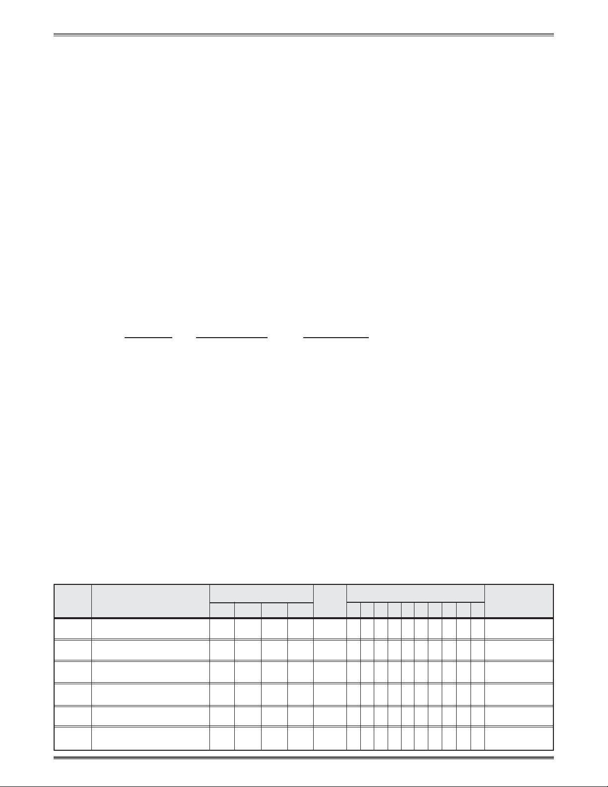
THE TABLE BELOW LISTS THE POSSIBLE CONFIGURATION(S) AND CORRESPONDING
COMMUNICATIONS ADAPTER(S) FOR YOUR PROJECTOR MANUFACTURER’S VARIOUS
MODELS. PLEASE NOTE THAT YOUR SWITCHER HAS BEEN CONFIGURED AS
INDICATED BY THE “✔” IN THE “Config as” COLUMN. IF Y OUR PROJECTOR MODEL
DIFFERS FROM THIS CONFIGURATION, YOU MUST RECONFIGURE Y OUR SWITCHER
WITH THE CORRECT SETTINGS.
PLEASE REFER TO THE FOLLOWING PAGES FOR COMPLETE CONFIGURATION AND
SIGNAL CONNECTION INSTRUCTIONS.
THIS SWITCHER HAS BEEN CONFIGURED FOR: EPSON EMP 5300/7100/
7300/7550
Config Model Rotary Switches Cable SW15 Settings Comm
as RS1 RS2 RS3 RS4 J2/J3 1 2 3 45678910Adapter
✔ EMP 5300/7100 0 0 E 2 J2 ↓↓↑↓↑↓↓ ↓↑↓26-484-01
✔ EMP 7300/7550 0 0 E 2 J2 ↓↓↑↓↑↓↓ ↓↑↓26-484-01
EMP 8000/7250 0 0 E 6 J2 ↓↓↑↓↑↓↓ ↓↑↓26-484-01
EMP 8100/7700 1 0 E 6 J2 ↓↓↑↓↑↓↓ ↓↑↓26-484-01
EMP 7600/5600 2 0 E 6 J2 ↓↓↑↓↑↓↓ ↓↑↓26-484-01
LUS
• User’s Manual • P/N 68-424-01 Rev. D
Page 1Extron • System 8/10 P
Page 2
Epson Installation Configuration and Connections
Epson 5300/7250/7300 Projector Configuration
Verify that the System 8/10 PLUS is already configured for the Epson 5300/7300
projector. The general setup is explained on page 3-4 and the switch settings for
the projector are repeated below.
1. Use a small screwdriver to remove the access cover from the System 8/10 PLUS
front panel. See bottom of page 3-3. The label on the back of the access cover
also has the configuration information.
__________ Before changing anything, remove the AC power cord to the System 8/10 P
to verify that the main power is OFF; also turn the projector power OFF.
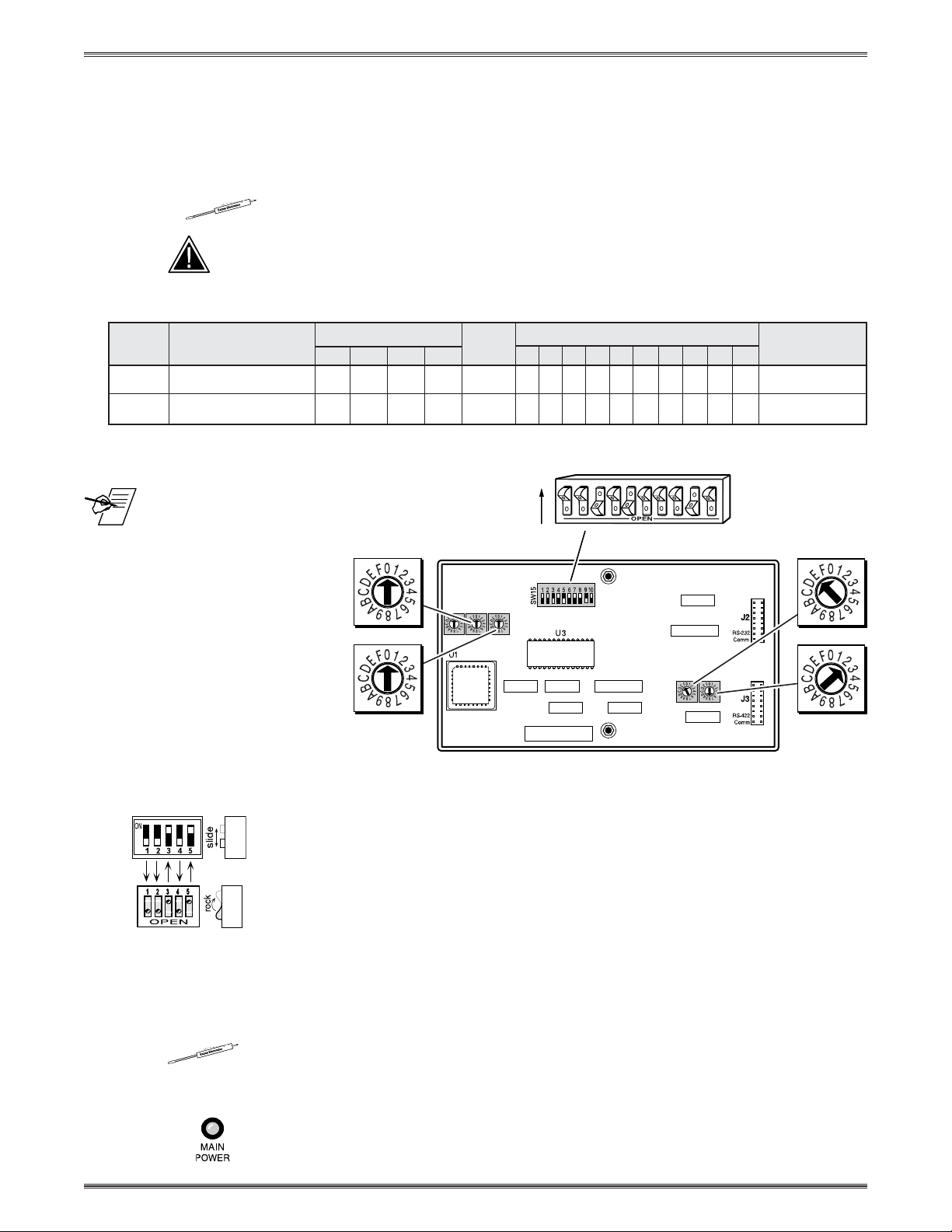
2. Set the switches as follows:
Config Model Rotary Switches Cable SW15 Settings Comm
as RS1 RS2 RS3 RS4 J2/J3 1 2 3 4 5 6 7 8 9 10 Adapter
✔ Epson 5300 0 0 E 2 J2 ↓↓↑↓↑↓ ↓↓↑↓ 26-484-01
✔ Epson 7300 0 0 E 2 J2 ↓↓↑↓↑↓ ↓↓↑↓ 26-484-01
2
3456 789101
SW15 DIP Switch
_ RS5 is for RGB switching
delay. See page 3-4 for
more information on switch
functions.
ON
RS2
LUS
RS3
RS1
RS5 RS2
RS1
RS3 RS4
Configured For:
RS-232
3. Use a grease pencil (or other rub-off marker) to mark the space on the label next
to “Epson 5300/7300”.
4. Locate the switcher’s Address DIP switches on the rear panel, lower right.
Unless this is part of a master/slave system, set #3 and #5 to the up position and
the others down. See illustration to the left.
Use the illustration on the facing page to do the following steps.
5. Connect the projector’s Com cable to the Com 1 DIN connector of the projector.
6. Connect the Comm Adapter’s 9-pin female connector to the 9-pin male
connector of the projector cable. Connect the other end of the Comm Adapter to
the Communications extension cable (CC-50' or CC-100').
7. Connect the CC cable to the 15-pin HD “Projector Control” port located on the
rear panel of the System 8/10 PLUS.
______ Secure the screws on all D connectors.
RS4
8. Connect the BNC (RGBS) cables from the System 8/10 PLUS outputs to the
Epson projector inputs according to the application requirements.
9. Apply Main Power to the System 8/10 PLUS by connecting the power cord. The
Main Power LED should light. Apply power to the projector.
LUS
• User’s Manual • P/N 68-424-01 Rev. D
Page 2Extron • System 8/10 P
Page 3

Epson Installation Configuration and Connections
10. Power on the projector with either the remote control or by pressing the
projector’s power button.
11. Press the projector’s Menu button, then select Options and enter this selection.
12. Select Mouse/Com 1, then select BNC Format RGB and enter this selection.
_ When the projector and switcher are communicating with each other, there will be a delay of
30 to 60 seconds when powering the projector on/off using the System 8/10 Plus.
Epson 5300/7300 Projector Connections
Use the illustration below when connecting the System 8/10 PLUS to an Epson
5300/7300 projector. Refer to Epson documentation to continue the installation.
3, 4 or 5 BNC
9-Pin
Male
9-Pin
○○○○○○○○○○○○○○○○○○○
See note
below
"I"
Comm
Adapter
26-484-01
"I"
CC 50'
15-Pin HD
_ You cannot input S-video and Composite video sources simultaneously
_ If the installation includes looping (master/slave) switchers, see Chapter 5.
If Video Loop Back is part of the installation, see pages 2-10 and 2-11.
LUS
• User’s Manual • P/N 68-424-01 Rev. D
Page 3Extron • System 8/10 P
Page 4

Epson Installation Configuration and Connections
Epson 8000/7250 Projector Configuration
Verify that the System 8/10 PLUS is already configured for the Epson 8000/7250
projector. The general setup is explained on page 3-4 and the switch settings for
the projector are repeated below.
1. Use a small screwdriver to remove the access cover from the System 8/10 PLUS
front panel. See bottom of page 3-3. The label on the back of the access cover
also has the configuration information.
__________ Before changing anything, remove the AC power cord to the System 8/10 P
to verify that the main power is OFF; also turn the projector power OFF.
2. Set the switches as follows:
Config Model Rotary Switches Cable SW15 Settings Comm
as RS1 RS2 RS3 RS4 J2/J3 1 2 3 4 5 6 7 8 9 10 Adapter
Epson 8000/7250 0 0 E 6 J2 ↓↓↑↓↑↓ ↓↓↑↓ 26-484-01
LUS
_ RS5 is for RGB switching
delay. See page 3-4 for
more information on switch
functions.
3. Use a grease pencil (or other rub-off marker) to mark the space on the label next
to “Epson 8000/7250”.
4. Locate the switcher’s Address DIP switches on the rear panel, lower right.
Unless this is part of a master/slave system, set #3 and #5 to the up position and
the others down. See illustration to the left.
Use the illustration on the facing page to do the following steps.
5. Connect the projector’s Com cable to the Com 1 DIN connector of the projector.
RS2
RS1
RS5 RS2
RS1
ON
Configured For:
RS-232
2
3456
SW15 DIP Switch
7
89101
RS3
RS4
RS3 RS4
6. Connect the Comm Adapter’s 9-pin female connector to the 9-pin male
connector of the projector cable. Connect the other end of the Comm Adapter to
the Communications extension cable (CC-50' or CC-100').
7. Connect the CC cable to the 15-pin HD “Projector Control” port located on the
rear panel of the System 8/10 PLUS.
______ Secure the screws on all D connectors.
8. Connect the BNC (RGBS) cables from the System 8/10 PLUS outputs to the
Epson projector inputs according to the application requirements.
9. Apply Main Power to the System 8/10 PLUS by connecting the power cord. The
Main Power LED should light. Apply power to the projector.
LUS
• User’s Manual • P/N 68-424-01 Rev. D
Page 4Extron • System 8/10 P
Page 5

Epson Installation Configuration and Connections
10. Power on the projector with either the remote control or by pressing the
projector’s power button.
11. Press the projector’s Menu button, then select Options and enter this selection.
12. Select Mouse/Com 1, then select BNC Format RGB and enter this selection.
_ When the projector and switcher are communicating with each other, there will be a delay of
30 to 60 seconds when powering the projector on/off using the System 8/10 Plus.
Epson 8000/7250 Projector Connections
Use the illustration below when connecting the System 8/10 PLUS to an Epson
8000/7250 projector. Refer to Epson documentation to continue the installation.
○○○○○○○○○○○○○○○○○○○○○○○
9-Pin
"I"
Comm
Adapter
26-484-01
"I"
CC 50'
15-Pin HD
3, 4 or 5 BNC
Male
9-Pin
_ If the installation includes looping (master/slave) switchers, see Chapter 5.
If Video Loop Back is part of the installation, see pages 2-10 and 2-11.
LUS
• User’s Manual • P/N 68-424-01 Rev. D
Page 5Extron • System 8/10 P
 Loading...