

Page 1
TM
BrightLink 455Wi
Installation Guide
Guide d’installation
Page 2
Safety Instructions
For your safety, read all the instructions in this guide before using the setting plate. Incorrect handling that
ignores instructions in this guide could damage the setting plate or could result in personal injury or property
damage. Keep this installation guide at hand for future reference.
Read the safety instructions in the User's Guide for your projector and follow the instructions in this
document.
Explanation of Symbols
The warning marks shown below are used throughout this installation guide to prevent personal injury or
property damage. Make sure you understand these warnings when reading this installation guide.
Warning
Caution
This symbol indicates information that, if ignored, could possibly result in personal injury or even death
due to incorrect handling.
This symbol indicates information that, if ignored, could possibly result in personal injury or physical
damage due to incorrect handling.
Symbol indicating an action that must not be done
Symbol indicating an action that should be done
Safety Precautions for Installation
Warning
The setting plate is designed specifically for mounting a projector to a wall. If anything other than a
projector is mounted, the weight may result in damage.
If the setting plate falls, it could cause personal injury or property damage.
The installation work (wall mounting) should be performed by specialists who have technical knowledge
and ability. Incomplete or incorrect installation could cause the setting plate to fall and cause personal
injury or property damage. Contact the customer support office listed in “Where to Get Help” in the User's
Guide for your projector when installing the setting plate.
Follow the instructions in this guide when installing the setting plate.
If the instructions are not followed, the setting plate may fall, resulting in personal injury or property damage.
Handle the power cable carefully.
Incorrect handling may cause fire or electric shock. Observe the following precautions when handling:
• Do not handle the power plug with wet hands.
• Do not use a power cable that is damaged or modified.
• Do not pull the power cable with too much force when routing the cable through the setting plate.
When you mount the projector on the wall with the setting plate, the wall requires enough strength to hold
the projector and the setting plate. Confirm the weight of the projector and the setting plate before
installation, and maintain the strength of the wall. If the wall is not strong enough, reinforce the wall
before installation.
Do not install the setting plate in a place where it might be subjected to vibration or shock.
Vibration or shock could cause damage to the projector or mounting surface. It could also cause the setting plate or
projector to fall and cause personal injury or property damage.
Install the setting plate so that it can sufficiently support the weight of the projector and setting plate, and
resist any horizontal vibration. Use M8 nuts and bolts.
Nuts and bolts smaller than M8 could cause the setting plate to fall. Epson takes no responsibility for any damage or
injury caused by incorrect installation.
2
Page 3
Warning
The installation work should be performed by at least two qualified service personnel. If you need to
loosen any screws during installation, be careful not to drop the setting plate.
If the setting plate or projector falls, it could cause personal injury or property damage.
Inspect the setting plate on a regular basis to ensure there are no broken parts or loose screws.
If there are any broken parts, stop using the setting plate immediately. If the setting plate or projector falls, it could cause
personal injury or property damage.
Never modify the setting plate.
Do not hang on the setting plate or hang a heavy object on the setting plate.
If the projector or setting plate falls, it could cause personal injury or property damage.
If you use adhesives to prevent the screws from loosening or things such as lubricants or oils on the slide
plate fixing part of the projector, the case may crack and cause the projector to fall, resulting in personal
injury or property damage. Do not use adhesives, lubricants, or oils to install or adjust the setting plate.
Tighten all screws firmly after adjustment.
If the screws are not tightened firmly, the projector or setting plate may fall and cause personal injury or property
damage.
Never loosen the bolts and nuts after installation.
Confirm that the screws have not become loose on a regular basis. If you find any loose screws, tighten them firmly. If the
screws are not tightened firmly, the projector or setting plate may fall and cause personal injury or property damage.
English
Caution
Do not install the setting plate in a location where the operating temperature for your projector model
may be exceeded.
Such an environment may damage the projector.
Install the setting plate in a place free from excessive dust and humidity to prevent the lens or optical
components from becoming dirty.
Do not use excessive force when adjusting the setting plate.
The setting plate may break, resulting in personal injury.
Location
• Before installing the projector, verify the power supply wiring for the installation location.
• Install the projector away from other electric devices such as fluorescent lights or air conditioners. Some
kinds of fluorescent lights could interfere with the remote control of the projector.
• Install the projector away from direct sunlight and other bright light sources.
• It is recommended to keep connection cable length less than 65 ft (20 meters) to reduce external noise.
• Install the setting plate in a place free from excessive dust and humidity to prevent the lens or optical
components from becoming dirty.
About This Installation Guide
This guide describes how to mount the BrightLink™ 455 Wi projector to a wall using the exclusive setting
plate.
3
Page 4
1 Package Contents
s Page 5
2 Specifications
3 Connecting Devices
4 Positioning the Projector
(1) Installation worksheet for projecting on a pre-installed wall-
mounted board
(2) Installation worksheet for projecting on a plain wall
(3) Installation measurements in inches
(4) Installation measurements in millimeters
5 Installing the Projector
(1) Install the wall plate on the wall
(2) Determine the projection distance and pull out the slider
(3) Attach the setting plate to the wall plate
(4) Secure the projector to the setting plate
(5) Connect the power cable and other cables to the projector
s Page 7
s Page 8
s Page 9
s Page 17
6 Adjusting the Image
(1) Turn on the projector
(2) Display the test pattern
(3) Change the aspect ratio if necessary
(4) Adjust the focus
(5) Use the left adjustment dial to adjust the horizontal roll
(6) Use the right adjustment dial to adjust the horizontal rotation
(7) Use the top adjustment dial to adjust the vertical tilt
(8) Adjust the vertical position
(9) Adjust the forward/backward slide
(10) Turn off the display of the test pattern or computer image
7 Attaching the Covers
(1) Attach the wall plate cover and end cap
(2) Attach the cable cover to the projector
s Page 21
s Page 26
4
Page 5
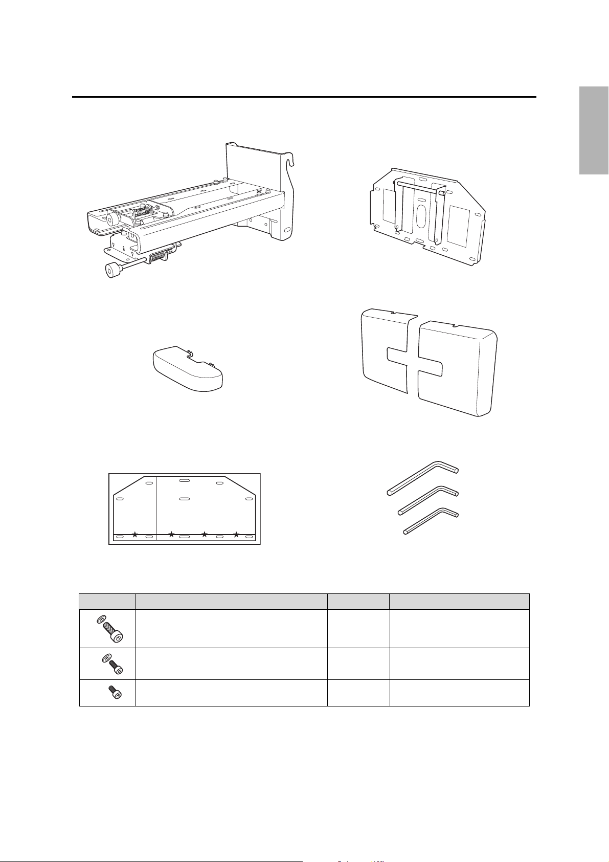
1. Package Contents
Mounting hardware
English
Setting plate (wall mount)
End cap
Template sheet
(for installing the wall plate)
Wall plate
Wall plate cover
Hexagon wrenches (for M4, M5, and M8)
Shape Name Quantity Application
M8 x 15 mm hexagon socket head cap bolt with
washer
M5 x 12 mm hexagon socket head cap bolt with
washer
M4 x 12 mm hexagon socket head cap bolt without
washer
2 For installing setting plate
2 For securing projector
2 For installing wall plate cover
• Use the bolts supplied with the setting plate to install it, as directed in this guide. Do not substitute these
bolts with any other types.
• Use commercially available M8 x 50 mm anchors (at least 3) or 8 x 80 mm lag bolts (at least 3) to attach the
wall plate to the wall.
• Gather the tools and parts you need before you begin installation.
5
Page 6
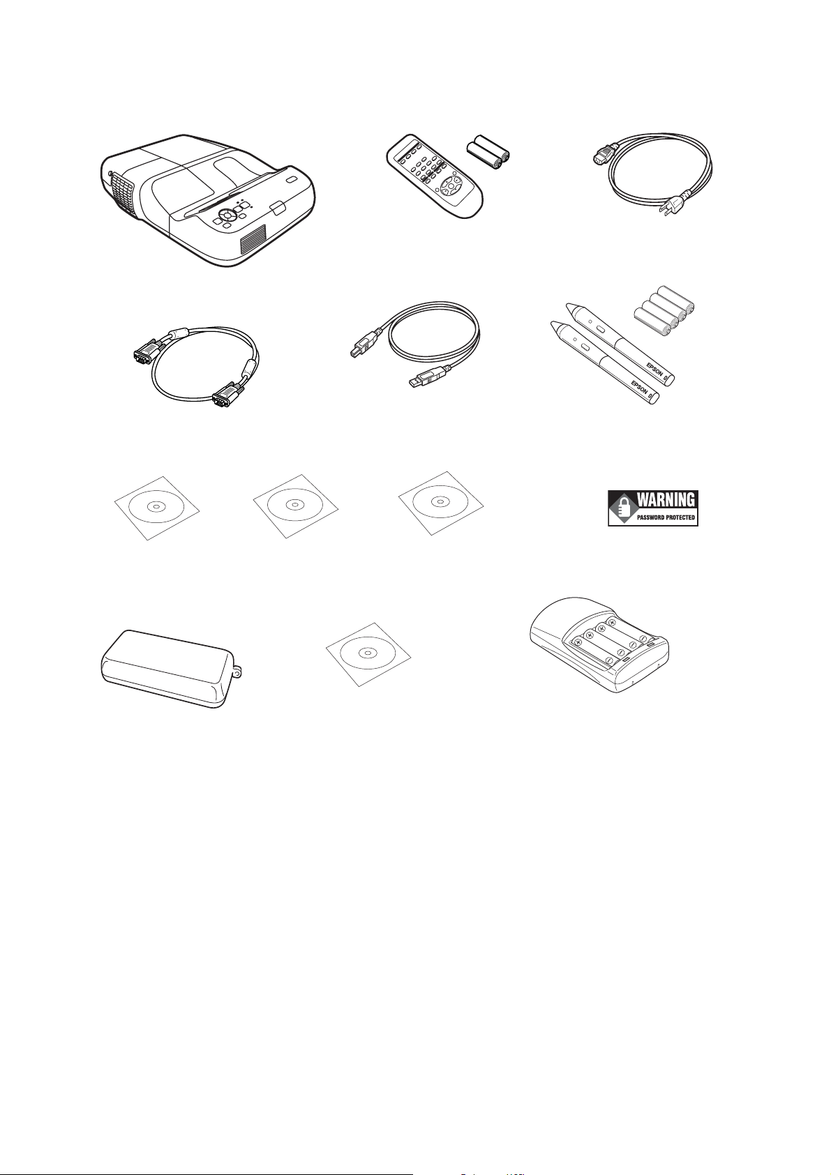
Projector box
S
Projector
VGA computer cable
Epson Projector
oftware for Easy
Interactive Function CD
BrightLink
455Wi CD
Remote control
and AA batteries
USB cable
Epson Projector
Software CD
Power cord
Interactive pens and
AAA batteries
Security sticker
Pen tray
TeamBoard Draw CD
Battery charger with 4 AAA
rechargeable batteries
(for interactive pens)
6
Page 7
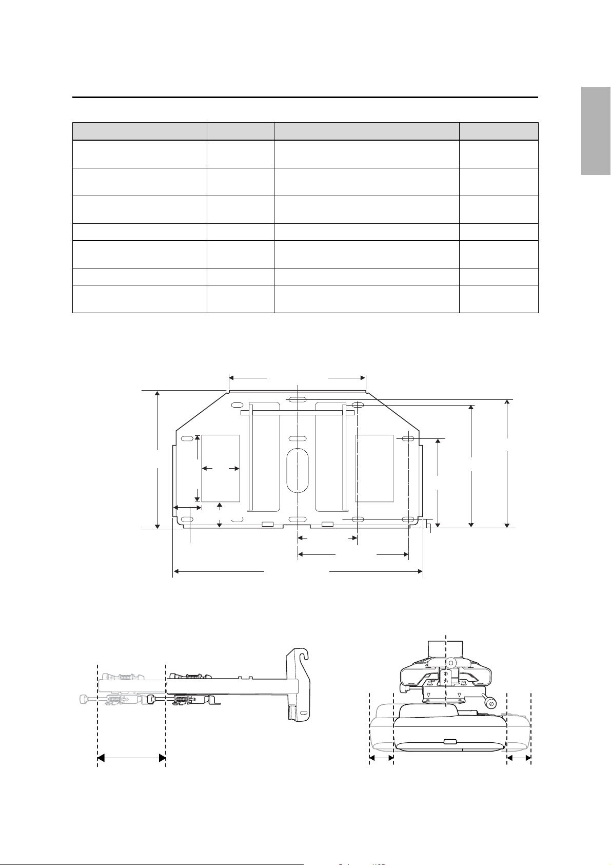
2. Specifications
Item Specification Remark Reference Page
Setting plate weight Approx. 13.89 lb
(6.3 kg)
Forward/backward slide
adjustment range
Vertical slide adjustment range 4 ° Minimum: 1.10 in. (28 mm)
Vertical tilt adjustment range ± 5 ° Fine adjustments possible with adjustment dial
Horizontal rotation adjustment
range
Horizontal roll adjustment range ± 3 ° Fine adjustments possible with adjustment dial
Horizontal slide adjustment range ± 1.77 in.
0 to 11.81 in.
(300 mm)
± 5 ° Fine adjustments possible with adjustment dial
(45 mm)
Wall plate
Wall plate 4.85 lb (2.2 kg)
Covers and cap 1.04 lb (0.47 kg)
Maximum: 1.67 in. (42.5 mm)
English
Refer to the figure
below
s 25
s 24
s 24
s 23
Refer to the figure
below
9.71 (247)
4.75
(121)
3.0
(76)
1.81 (46)
1.8 (46)
Setting plate adjustment range
9.87 (250)
4.4 (112)
17.97 (456)
[Unit: in. (mm)]
9.05 (230)
8.74 (222)
6.3 (160)
0.59 (15)
8 (203.2)
Forward/backward slide adjustment range:
0 to 11.81 in. (300 mm)
Horizontal slide adjustment range:
± 1.77 in. (45 mm)
7
Page 8
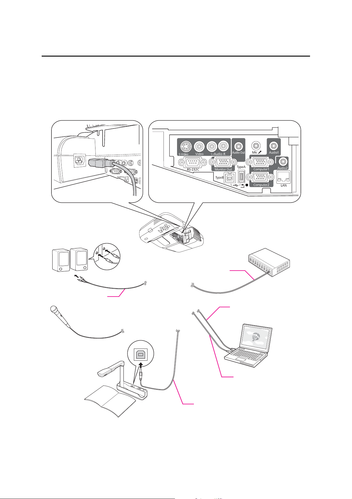
3. Connecting Devices
Make sure you have the power cable, computer cable, USB cable, and other parts at the location where the
setting plate is to be installed.
Make sure you have all necessary cables for any devices, such as a document camera or microphone, that you
will connect to the projector.
Power cord
Connection Example
External speakers
Audio cable
(commercially available product)
Microphone
Document camera
LAN device
LAN cable
Computer cable
(for computer video output)
Computer
USB cable
(for Easy Interactive Function)
Dedicated USB cable
(supplied with document camera)
8
Page 9
4. Positioning the Projector
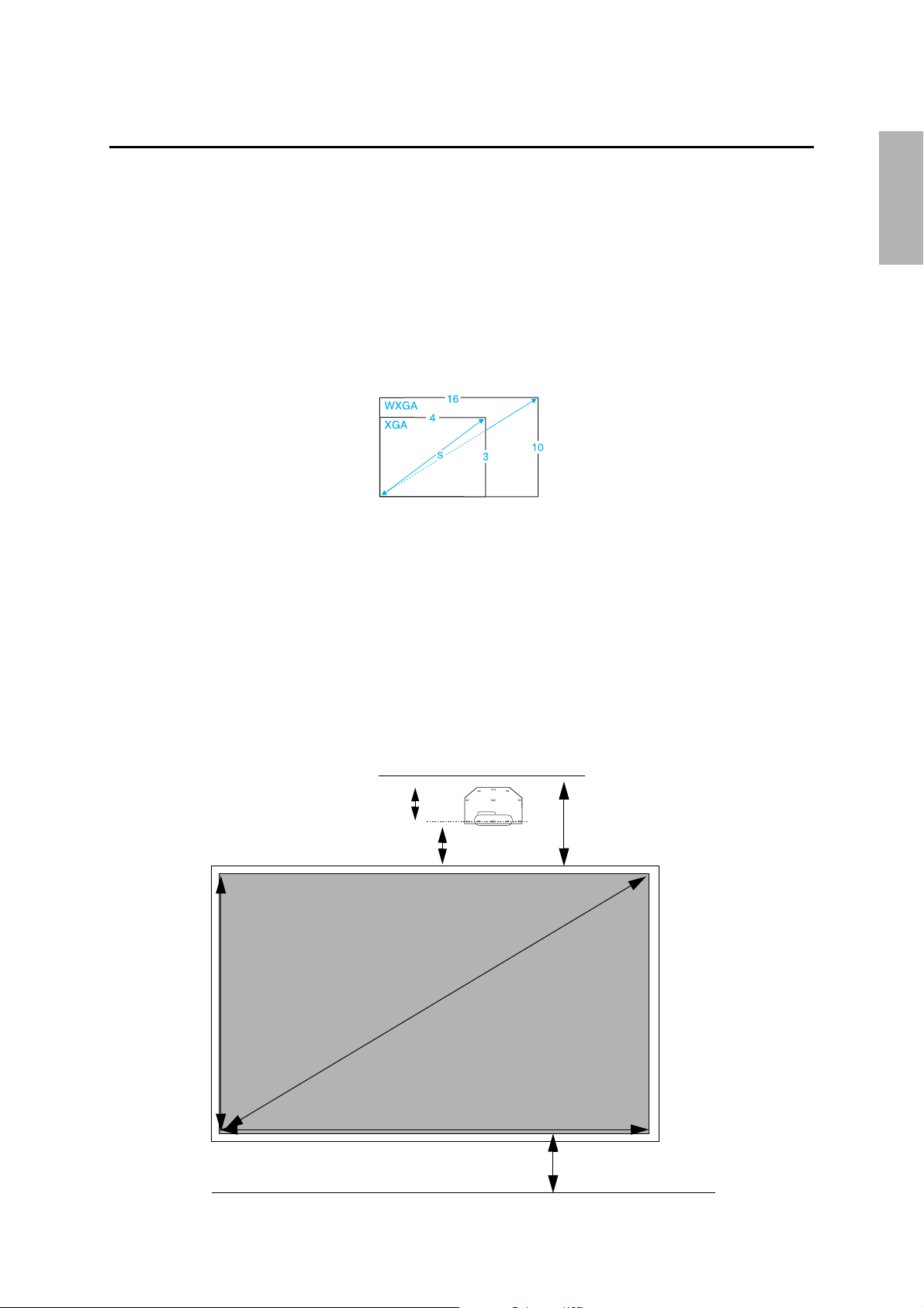
The BrightLink 455Wi can project up to 96 inches diagonally for a WXGA image or 85 inches diagonally for an
XGA image. You can project onto a pre-installed whiteboard or directly onto a plain wall. The height of the
included wall mount determines the maximum image size and how high the image appears on the wall or
whiteboard. The distance of the projector from the wall (once it is mounted on the adjustable arm of the
setting plate) also affects image size and position.
If you are planning to project on a whiteboard, the image may not fill the entire board, depending on the
aspect ratio. If you match the image height to the board’s height, gaps may appear on the sides of the board.
Use the following worksheets to determine the proper location of the wall plate on the wall. If you are
projecting onto a pre-installed whiteboard, use the worksheet below. If you are projecting on a plain wall, use
the worksheet on page 10.
Installation worksheet for projecting on a pre-installed wall-mounted board
English
(1) Measure the ceiling height (distance from the floor to the ceiling).
(2) Measure the height of the board’s image area (h).
(3) Measure the width of the board’s image area (w).
(4) Measure the distance from the floor to the bottom of the board’s
image area (f).
(5) Measure the distance from the ceiling to the top of the board’s image area (c).
(6) Measure the thickness of the board (x).
10 in. (254 mm)—height of
wall plate plus cover
Required distance from top
of image area to wall plate (b)
Height of
image area (h)
Diagonal size of
image area (S)
Distance from ceiling to
top of image area (c)
_____
_____ (h)
_____ (w)
_____ (f)
_____ (c)
_____ (x)
Width of image area (w)
Distance from floor to
bottom of image area (f)
9
Page 10

(7) Determine the aspect ratio of the board or of the images that will be
projected. For new computers or laptops, this will most likely be WXGA
(16:10). For older equipment, this will most likely be XGA (4:3). You may need
to consult your IT director for this information.
4:3 XGA 16:10 WXGA 16:9 Widescreen
(8) Using the tables on pages 12 to 15 for your aspect ratio and desired image
height (h), find the required distance between the top of the image area and
the wall plate (b).
_____ (b)
(9) Determine the position for your projector installation by adding the values for
(f), (h), and (b), plus an additional 10 inches for the height of the wall plate
plus the cover.
If the ceiling height of your room (as noted in step 1) does not meet the
minimum ceiling height required for your board, you may need to select a
smaller image size or move the board to a lower position on the wall.
(10)After confirming your image size, use tape or a pencil to mark the distance (b)
from the top of the image area on the board to the bottom of the wall plate.
(11)Align the line (horizontal) on the template sheet with the (b) mark, then
align the center line on the template sheet with the center of the image area.
Follow the instructions on page 17 to install the projector.
Installation worksheet for projecting on a plain wall
(1) Measure the ceiling height (distance from the floor to the ceiling).
(2) Determine the desired aspect ratio of the image. For new computers or
laptops, this will most likely be WXGA (16:10). For older equipment, this will
most likely be XGA (4:3). You may need to consult your IT director for this
information.
4:3 XGA 16:10 WXGA 16:9 Widescreen
(3) Using the tables on pages 12 to 15 for your aspect ratio, select the largest
image size available for your ceiling height.
Image height (h)
Image width (w)
(4) Determine the desired distance from the floor to the bottom of the image
area (f).
The recommended minimum distance is 30 inches. Images appearing less
than 28 inches from the floor may be obstructed for some viewers.
(5) Find the top of the projected image area by adding distances (f) and (h).
_____ (f)
_____ (h)
_____ (b)
+10
inches
_____ total
_____
_____ (h)
_____ (w)
_____ (f)
_____
(6) Use the tables on pages 12 to 15 to determine the required distance from the
top of the image area to the bottom of the wall plate (b).
(7) Add:
Required distance from top of image area to wall plate (b)
Height of image area (h)
Distance from floor to bottom of image area (f)
Height of wall plate plus cover
If the total exceeds the ceiling height, you will need to reduce the image size
or reduce the distance from the floor to the bottom of the image area.
10
_____ (b)
_____ (b)
_____ (h)
_____ (f)
inches
+10
_____ total
Page 11
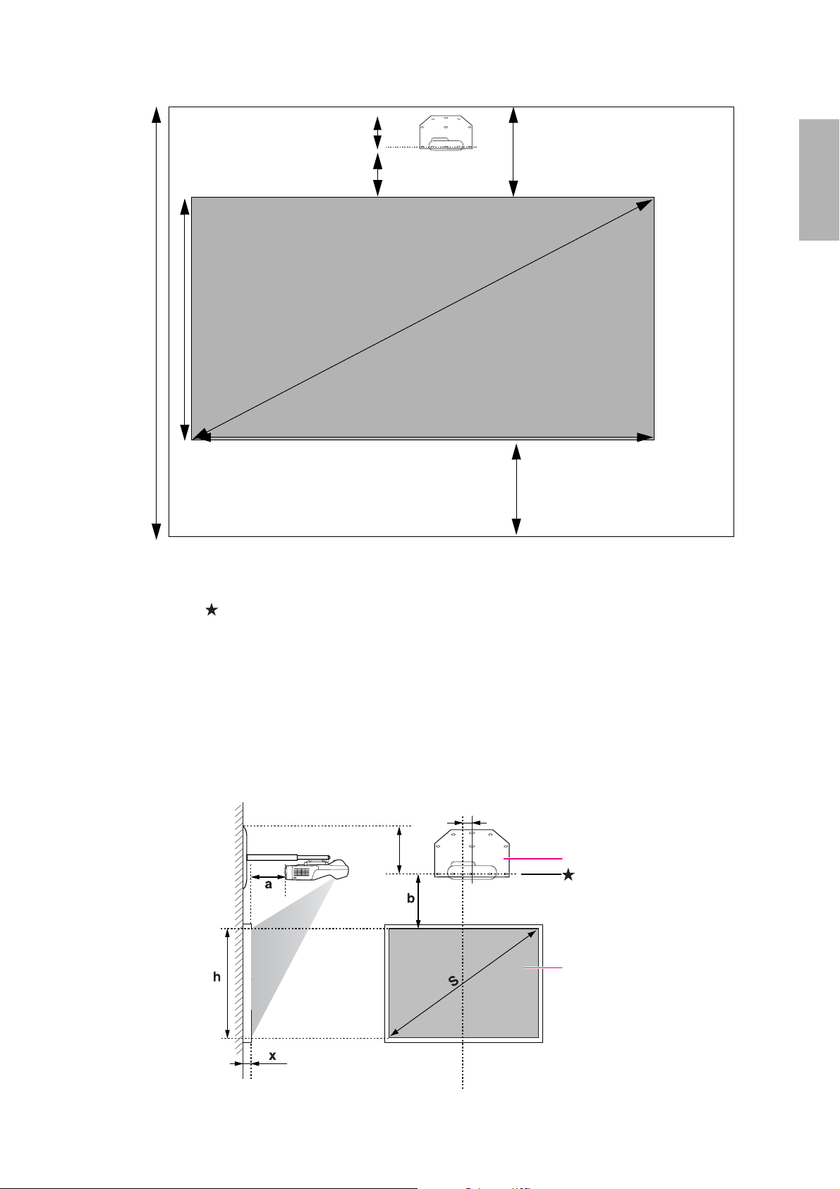
10 in. (254 mm) —height
of wall plate plus cover
Required distance from top
of image area to wall plate (b)
Distance from ceiling to
top of image area (c)
English
Ceiling
height
Height of
image area (h)
Diagonal image
size (S)
Width of image area (w)
Distance from floor to
bottom of image area (f)
(8) After confirming your image size, use tape or a pencil to mark the distance (b) from the top of
the image area on the board to the bottom of the wall plate.
(9) Align the line (horizontal) on the template sheet with the (b) mark, then align the center
line on the template sheet with the center of the image area. Follow the instructions on page
17 to install the projector.
The tables on the following pages provide installation information for all supported image sizes. The
minimum ceiling height is based on an image 30 inches from the floor; if the image is lower, the minimum
ceiling height is reduced by the corresponding measurement.
Use the worksheets, the illustration below, and the information in the tables on the following pages to
determine the projection distance and placement of the wall plate. The recommended range for projection
distance (a) is 2.76 to 14.57 inches (7 to 37 cm).
2.55 in. (65 mm)
10 in. (254 mm)
Distance from wall of projection
surface or whiteboard
11
Offset value for the position of
the center of the screen and the
center of the wall plate
Wall plate
Line on template
Projection surface
Page 12
Distance
from top
of image
to wall
plate (b)
Min.
Projection
Image
height
width
Image
Min.
ceiling
Distance
from top
Min.
projection
Image
height
width
Image
distance
(h)
(w)
height*
of image
distance
(h)
(w)
(a)
to wall
plate (b)
(a)
Min.
ceiling
height*
Installation measurements in inches
Distance
from top
of image
Min.
distance
projection
Image
height
width
Image
Min.
ceiling
size
image
(h)
(w)
height*
(S)
16:10 WXGA 4:3 XGA 16:9 Widescreen
Diagonal
to wall
plate (b)
(a)
— — — — — 83.8 44.0 33.0 3.7 10.8 — — — — —
55”
— — — — — 84.6 44.8 33.6 4.1 11.0 — — — — —
56”
— — — — — 85.4 45.6 34.2 4.4 11.2 — — — — —
57”
— — — — — 86.2 46.4 34.8 4.8 11.4 — — — — —
58”
81.6 50.0 31.3 2.7 10.3 86.9 47.2 35.4 5.2 11.5 — — — — —
59”
82.3 50.9 31.8 3.0 10.5 87.7 48.0 36.0 5.5 11.7 81.8 52.3 29.4 3.5 12.4
60”
83.0 51.7 32.3 3.3 10.6 88.5 48.8 36.6 5.9 11.9 82.5 53.2 29.9 3.9 12.6
61”
83.7 52.6 32.9 3.6 10.8 89.3 49.6 37.2 6.2 12.1 83.1 54.0 30.4 4.2 12.8
62”
84.3 53.4 33.4 4.0 11.0 90.0 50.4 37.8 6.6 12.2 83.8 54.9 30.9 4.5 12.9
63”
85.0 54.3 33.9 4.4 11.1 90.8 51.2 38.4 7.0 12.4 84.5 55.8 31.4 4.8 13.1
64”
85.7 55.1 34.4 4.6 11.3 91.6 52.0 39.0 7.3 12.6 85.2 56.7 31.9 5.2 13.3
65”
86.4 56.0 35.0 4.9 11.4 92.4 52.8 39.6 7.7 12.8 85.9 57.5 32.4 5.5 13.5
66”
87.1 56.8 35.5 5.2 11.6 93.1 53.6 40.2 8.0 12.9 86.5 58.4 32.8 5.8 13.7
67”
87.8 57.7 36.0 5.5 11.7 93.9 54.4 40.8 8.4 13.1 87.2 59.3 33.3 6.2 13.9
68”
88.4 58.5 36.6 5.9 11.9 94.7 55.2 41.4 8.8 13.3 87.9 60.1 33.8 6.5 14.1
69”
89.1 59.4 37.1 6.2 12.0 95.5 56.0 42.0 9.1 13.5 88.6 61.0 34.3 6.8 14.2
70”
89.8 60.2 37.6 6.5 12.2 96.2 56.8 42.6 9.5 13.6 89.2 61.9 34.8 7.2 14.4
71”
90.5 61.1 38.2 6.8 12.3 97.0 57.6 43.2 9.8 13.8 89.9 62.8 35.3 7.5 14.6
72”
91.2 61.9 38.7 7.1 12.5 97.8 58.4 43.8 10.2 14.0 90.6 63.6 35.8 7.8 14.8
73”
91.9 62.8 39.2 7.5 12.7 98.6 59.2 44.4 10.6 14.2 91.3 64.5 36.3 8.1 15.0
74”
92.6 63.6 39.7 7.8 12.8 99.3 60.0 45.0 10.9 14.3 91.9 65.4 36.8 8.4 15.2
75”
93.2 64.4 40.3 8.1 13.0 100.1 60.8 45.6 11.3 14.5 92.6 66.2 37.3 8.8 15.4
76”
12
Page 13

Distance
from top
of image
to wall
plate (b)
English
Min.
Projection
Image
height
width
Image
Min.
ceiling
Distance
from top
Min.
projection
Image
height
width
Image
(a)
distance
(h)
(w)
height*
to wall
plate (b)
of image
(a)
distance
(h)
(w)
11.7 17.0
12.0 17.2
12.4 17.4
12.7 17.6
13.0 17.9
13.3 18.0
13.7 18.2
41.7
42.2
42.7
43.1
43.6
44.1
44.6
Min.
Distance
Min.
16:10 WXGA 4:3 XGA 16:9 Widescreen
Image
Image
Min.
image
Diagonal
ceiling
height*
from top
of image
distance
projection
(h)
height
(w)
width
ceiling
height*
(S)
size
to wall
(a)
plate (b)
93.9 65.3 40.8 8.4 13.1 100.9 61.6 46.2 11.7 14.7 93.3 67.1 37.8 9.1 15.5
77”
94.6 66.1 41.3 8.7 13.3 101.7 62.4 46.8 12.0 14.9 94.0 68.0 38.2 9.4 15.7
78”
95.3 67.0 41.9 9.0 13.4 102.4 63.2 47.4 12.4 15.0 94.6 68.9 38.7 9.7 15.9
79”
96.0 67.8 42.4 9.4 13.6 103.2 64.0 48.0 12.7 15.2 95.3 69.7 39.2 10.1 16.1
80”
96.7 68.7 42.9 9.7 13.7 104.0 64.8 48.6 13.1 15.4 96.0 70.6 39.7 10.4 16.3
81”
97.3 69.5 43.5 10.0 13.9 104.8 65.6 49.2 13.5 15.6 96.7 71.5 40.2 10.7 16.5
82”
98.0 70.4 44.0 10.3 14.0 105.5 66.4 49.8 13.8 15.7 97.4 72.3 40.7 11.1 16.7
83”
98.7 71.2 44.5 10.6 14.2 106.3 67.2 50.4 14.2 15.9 98.0 73.2 41.2 11.4 16.9
84”
99.4 72.1 45.0 11.0 14.4 107.1 68.0 51.0 14.5 16.1 98.7 74.1
85”
100.1 72.9 45.6 11.3 14.5 — — — — — 99.4 75.0
86”
100.8 73.8 46.1 11.6 14.7 — — — — — 100.1 75.8
87”
101.5 74.6 46.6 11.9 14.8 — — — — — 100.7 76.7
88”
102.1 75.5 47.2 12.2 14.9 — — — — — 101.4 77.6
89”
102.8 76.3 47.7 12.6 15.1 — — — — — 102.1 78.4
90”
103.5 77.2 48.2 12.9 15.3 — — — — — 102.8 79.3
91”
104.2 78.0 48.8 13.2 15.4 — — — — — 103.4 80.2 45.1 14.0 18.3
92”
104.9 78.9 49.3 13.5 15.6 — — — — — 104.1 81.1 45.6 14.3 18.5
93”
105.6 79.7 49.8 13.8 15.8 — — — — — — — — — —
94”
106.3 80.6 50.3 14.2 15.9 — — — — — — — — — —
95”
106.9 81.4 50.9 14.5 16.1 — — — — — — — — — —
96”
* Based on an image 30 inches from the floor; if the image is lower, the minimum ceiling height is reduced by the corresponding measurement.
13
Page 14
Distance
from top
of image
to wall
plate (b)
Min.
Projection
Image
height
width
Image
Min.
ceiling
Distance
from top
Min.
projection
Image
height
width
Image
distance
(h)
(w)
height*
of image
distance
(h)
(w)
(a)
to wall
plate (b)
(a)
Installation measurements in millimeters
Min.
Distance
Min.
Image
16:10 WXGA 4:3 XGA 16:9 Widescreen
Image
Min.
image
Diagonal
ceiling
from top
projection
height
width
ceiling
size
height*
of image
distance
(h)
(w)
height*
(S)
to wall
plate (b)
(a)
— — — — — 2129 1118 838 94 275 — — — — —
55”
— — — — — 2149 1138 853 104 280 — — — — —
56”
— — — — — 2188 1158 869 113 284 — — — — —
57”
— — — — — 2208 1179 884 122 289 — — — — —
58”
2073 1271 794 68 262 2228 1199 899 131 293 — — — — —
59”
2090 1292 808 76 266 2248 1219 914 140 297 2078 1328 747 90 314
60”
2107 1314 821 84 270 2267 1240 930 149 302 2095 1350 760 98 319
61”
2125 1335 835 92 274 2287 1260 945 158 306 2112 1373 772 106 324
62”
2142 1357 848 100 278 2307 1280 960 168 311 2129 1395 785 114 329
63”
2160 1379 862 108 282 2326 1300 975 177 315 2146 1417 797 123 333
64”
2177 1400 875 117 286 2346 1321 991 186 320 2163 1439 809 131 338
65”
2194 1422 888 125 290 2366 1341 1006 195 324 2181 1461 822 139 343
66”
2212 1443 902 133 294 2385 1361 1021 204 329 2198 1483 834 148 348
67”
2229 1465 915 141 298 2405 1382 1036 213 333 2215 1505 847 156 352
68”
2247 1486 929 149 302 2425 1402 1052 223 338 2232 1528 859 164 357
69”
2264 1508 942 157 306 2444 1422 1067 232 342 2249 1550 872 173 362
70”
2281 1529 956 165 310 2464 1443 1082 241 346 2267 1572 884 181 366
71”
2299 1551 969 173 313 2487 1463 1097 250 351 2284 1594 897 189 371
72”
2316 1572 983 181 317 2504 1483 1113 259 355 2301 1616 909 198 376
73”
2334 1594 996 189 321 2523 1504 1128 268 360 2318 1638 921 206 381
74”
2351 1615 1010 197 325 2510 1524 1143 277 364 2335 1660 934 214 385
75”
2368 1637 1023 205 329 2543 1544 1158 287 369 2352 1682 946 223 390
76”
14
Page 15
Distance
from top
of image
to wall
plate (b)
English
Min.
Projection
Image
height
width
Image
Min.
ceiling
Distance
from top
Min.
projection
Image
height
width
Image
(a)
distance
(h)
(w)
height*
to wall
plate (b)
of image
(a)
distance
(h)
(w)
Min.
Distance
Min.
16:10 WXGA 4:3 XGA 16:9 Widescreen
Image
Image
Min.
image
Diagonal
ceiling
height*
from top
of image
distance
projection
(h)
height
(w)
width
ceiling
height*
(S)
size
to wall
(a)
plate (b)
2386 1659 1037 214 333 2563 1565 1173 296 373 2370 1705 959 231 395
77”
2403 1680 1050 222 337 2582 1585 1189 305 378 2387 1727 971 239 400
78”
2420 1702 1063 230 341 2602 1605 1204 314 382 2404 1749 984 247 404
79”
2438 1723 1077 238 345 2622 1626 1219 323 389 2421 1771 996 256 409
80”
2455 1745 1090 246 349 2641 1646 1234 332 391 2438 1793 1009 264 414
81”
2473 1766 1104 254 353 2661 1666 1250 342 395 2456 1815 1021 272 418
82”
2490 1788 1117 262 357 2681 1687 1265 351 400 2473 1837 1034 281 423
83”
2507 1809 1131 270 361 2700 1707 1280 360 404 2490 1860 1046 289 428
84”
2525 1831 1144 278 365 2720 1727 1295 369 409 2507 1882 1058 297 433
85”
2542 1852 1158 286 369 — — — — — 2524 1904 1071 306 437
86”
2560 1874 1171 294 372 — — — — — 2542 1926 1083 314 442
87”
2577 1895 1185 303 376 — — — — — 2559 1948 1096 322 447
88”
2594 1917 1198 311 380 — — — — — 2576 1970 1108 331 452
89”
2612 1939 1212 319 384 — — — — — 2593 1992 1121 339 456
90”
2629 1960 1225 327 388 — — — — — 2610 2015 1133 347 461
91”
2647 1982 1239 335 392 — — — — — 2627 2037 1146 356 466
92”
2664 2003 1252 343 396 — — — — — 2645 2059 1158 364 471
93”
2681 2025 1265 351 400 — — — — — — — — — —
94”
2699 2046 1279 359 404 — — — — — — — — — —
95”
2716 2068 1292 367 408 — — — — — — — — — —
96”
* Based on an image 762 mm from the floor; if the image is lower, the minimum ceiling height is reduced by the corresponding measurement.
15
Page 16
If you have a pre-existing whiteboard, refer to the table below to identify common models and sizes. If your
board is listed here, use the dimensions to reference the installation requirements found on pages 12 to 15.
Interactive whiteboard sizes
Diagonal size 16:10 WXGA 4:3 XGA 16:9 Widescreen
60 inches — — RM ClassBoard2 60
63 inches — Hitachi® StarBoard FX-63 —
64 inches — SMART Board 660
Promethean ActivBoard 164
71 inches — — INTERWRITE BOARD 1071
77 inches — Hitachi Cambridge Board 77
Hitachi StarBoard FX-77
SMART Board 680
77.5 inches — RM ClassBoard2 77.5
INTERWRITE® BOARD 1077
78 inches PolyVision® TS 600/ TS610 /
TSL610/ENO 2610
82 inches — — Hitachi StarBoard FX-82W
85 inches — — INTERWRITE BOARD 1085
87 inches
93 inches — — PolyVision ENO 2810
94 inches — — SMART Board 690
96 inches Epson BrightLink 455Wi — —
SMART Board
Promethean ActivBoard 387
™ 685
PolyVision TS610
Promethean ActivBoard 178 / 378
——
—
—
—
—
16
Page 17
5. Installing the Projector
Make sure to follow the steps below to install the setting plate. If you ignore these steps, the setting plate
could fall and cause personal injury or property damage.
The maximum combined weight of the setting plate and the projector is approximately 33.5 lb
(15.2 kg). When you install the setting plate, calculate the permissible weight, carefully check
the construction, material, and strength of the wall, and perform the installation properly using
the most appropriate method.
A Install the wall plate on the wall
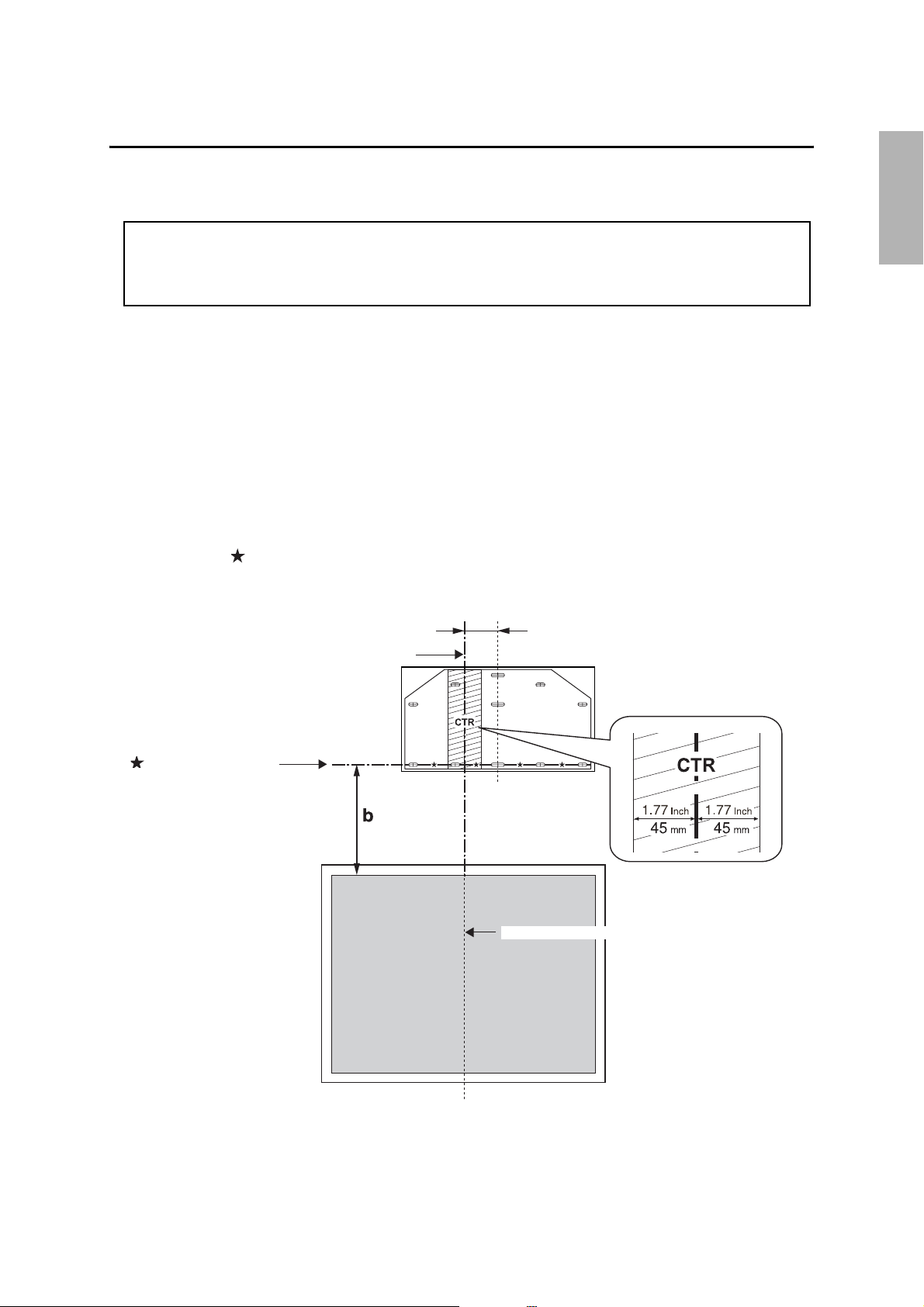
(1) Determine the template sheet position.
• From the tables on pages 12 to 15, confirm the screen size (S) and the distance between the
projection surface and wall plate (b).
• Align the CTR line (vertical) of the template sheet with the center line (vertical) of the projection
surface.
Confirm where the beams or studs are within the wall, and shift the position left or right as necessary.
The position can be shifted horizontally left or right from the center line of the projection surface by
up to 1.77 in. (45 mm).
• Align the line (horizontal) on the template with the height of (b).
English
CTR line of template sheet
line on template sheet
65 mm (2.55 in.)
Center line of projection surface
17
Page 18
Warning
❏ When you mount the projector on the wall with the setting plate, the wall needs to be
strong enough to hold the projector and the setting plate. Confirm the weight of the
projector and the setting plate before installation, and maintain the strength of the wall. If
the wall is not strong enough, reinforce the wall before installation.
❏ Install the setting plate so that it can sufficiently support the weight of the projector and
setting plate, and resist any horizontal vibration. Use M8 nuts and bolts. Nuts and bolts
smaller than M8 could cause the setting plate to fall.
❏ Epson takes no responsibility for any damage or injury caused by incorrect installation.
(2) Attach the template sheet to the wall.
If you need to install a junction box, you can use the cutout areas in the wall plate for the box.
The junction box needs to be recessed into the wall if you want to use the wall plate cover.
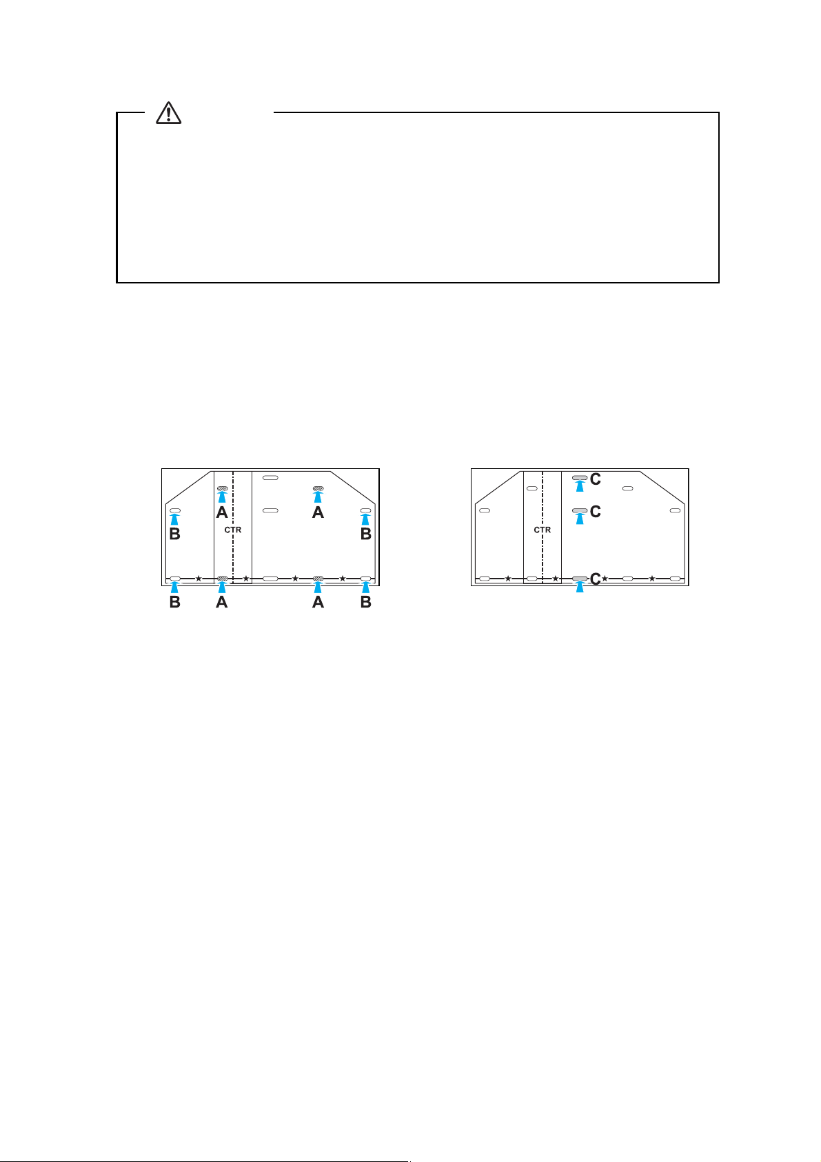
(3) Make mounting holes in the wall in the required locations.
The wall plate needs to be secured by commercially available anchors or lag bolts in the
following places. It is recommended that the wall plate be secured in at least three places.
• If securing the wall plate in four places, make the holes indicated by A or B in the figure.
• If securing the wall plate in three places, make the holes indicated by C in the figure.
Four mounting holes
(4) Remove the template sheet.
(5) Mount the wall plate on the wall.
Three mounting holes
B Determine the projection distance and pull out the slider
(1) Using the tables on pages 12 to 15, calculate the distance (a) from the projection surface to
the front of the projector.
(2) Loosen the four screws and pull out the slider on the setting plate.
18
Page 19

Align the slider with the mark on the slider measure that is a distance (a+x) equivalent to the
distance (a) plus the thickness of the board (x). See the tables on pages 12 to 15. The
recommended range for projection distance (a) is 2.76 to 14.57 in. (7 to 37 cm).
Screws (4 )
Slider measure
C Attach the setting plate to the wall plate
(1) Position the cables between the two screws and pass the cables through the setting plate
(
A).
(2) Hang the setting plate hook onto the wall plate bar (
B).
English
Caution
Take care not to trap the cables between the setting plate and wall plate.
(3) Tighten the two M8 x 15 mm hexagon socket head cap bolts and two M8 x 45 mm hexagon
socket head cap bolts supplied with the setting plate so that the setting plate becomes
vertical against the wall (
Use the two M8 x 45 mm hexagon socket head cap bolts to adjust the vertical position.
s 25
Setting plate
C).
Wall plate
Wall plate bar
Setting plate hook
Cables
M8 x 15 mm hexagon socket
head cap bolts (one on left
and one on right)
19
M8 x 45 mm hexagon
socket head cap bolts (2)
Page 20

D Secure the projector to the setting plate
(1) Loosen the two screws and remove the cable cover from the projector.
Screws (2)
Cable cover
(2) Insert the slide plate into the setting plate from the interface side of the projector (
Align the marks on the projector and the setting plate (
Slide plate
Projector
interface side
(3) Tighten the two M5 x 12 mm hexagon socket head cap bolts (
B).
M5 x 12 mm hexagon
socket head cap bolts (2)
Bolt positions
Marks
C).
Warning
If you use adhesives to prevent the screws from loosening or things such as lubricants or oils
on the slide plate, the case may crack and cause the projector to fall, resulting in personal
injury or property damage. Do not use adhesives, lubricants, or oils to install or adjust the
setting plate.
A).
20
Page 21

E Connect the power cable and other cables to the projector
Connect any necessary cables such as the power cable, computer cable, and USB cable to the projector.
Power cable
USB cable
Computer cable
If you are planning to run the cables inside the wall, make sure you follow all local electrical codes.
If you are running the cables outside the wall, use a cable management system to keep the cables
from obstructing the image. An optional cable management system is available from Epson
(part # ELPCK01).
English
6. Adjusting the Image
To ensure maximum projection screen quality, follow the steps below to adjust the projected image.
Do not make adjustments with the Keystone function of the projector. Doing so may
result in a reduction in image quality.
A Turn on the projector
Using Remote Control Using Control Panel
21
Page 22

B Display the test pattern
A
Press the Menu button and select the Settings menu - Pattern - Test Pattern. The test pattern is
optimized for a WXGA (16:10) image. If you want to change the aspect ratio, you need to connect a
computer and project an actual image, preferably a pattern that fills the whole screen.
To project an image from a laptop, you may need to Hold down the Fn key on the keyboard and press
the function key that lets you display on an external monitor. It may have an icon, or it may be labelled
CRT/LCD. You may need to hold down the Fn key while pressing it.
s User’s Guide for the projector: Settings menu
Using Remote Control Using Control Panel
C Change the aspect ratio if necessary
You must connect a computer before you can change the aspect ratio. Each time you press the Aspect
button on the remote control, the aspect name is displayed on the screen and the aspect ratio changes.
Change the setting according to the signal for the connected equipment.
Remote Control
Alternatively, set the aspect ratio from the Signal menu - Aspect. Following is a list of available aspect
settings:
• Normal: Displays images using the full projection area and maintains the aspect ratio of the image.
Choose this setting to automatically resize the image and make the best use of the display area.
• 16:9: Converts the aspect ratio of the image to 16:9. 4:3 ratio images are elongated horizontally to fit.
• Full: Displays images using the full width of the projection area, but does not retain the aspect ratio.
4:3 ratio images are elongated horizontally.
• Zoom: Displays images using the full width of the projection area and maintains the aspect ratio of
the image. The image may be cut off on the top and bottom depending on its aspect ratio.
• Native: Displays images as is (aspect ratio and resolution are maintained). Black bands may appear
or images may be cut off, depending on the resolution.
s User’s Guide for the projector: Configuration menu - Signal menu
spect Ratio
Full
22
Page 23

D Adjust the focus
(1) Move the air filter cover lever to open the air filter cover.
(2) Use the focus lever to adjust the focus.
Air filter cover
Air filter cover lever
Focus lever
(3) After you finish making the adjustment, close the air filter cover.
You may need to adjust the focus again after you adjust the image position.
E Use the left adjustment dial to adjust the horizontal roll
(1) Loosen the screw that corresponds to the left adjustment dial (A).
(2) Turn the adjustment dial to adjust the horizontal roll (
B).
English
(3) After you finish making all of the adjustments in steps
loosened in
A.
23
E to I, tighten the screw you
Page 24

F Use the right adjustment dial to adjust the horizontal rotation
(1) Loosen the two screws that correspond to the right adjustment dial (A).
(2) Turn the adjustment dial to adjust the horizontal rotation (
(3) After you finish making all of the adjustments in steps
loosened in
A.
B).
E to I, tighten the two screws you
G Use the top adjustment dial to adjust the vertical tilt
Repeat steps E to I as necessary.
(1) Loosen the screw that corresponds to the top adjustment dial (A).
(2) Turn the adjustment dial to adjust the vertical tilt (
(3) After you finish making all of the adjustments in steps
loosened in
A.
B).
E to I, tighten the screw you
24
Page 25

H Adjust the vertical position
(1) Adjust the vertical position, then tighten the two M8 x 15 mm hexagon socket head cap
bolts on the sides of the setting plate (
(2) Tighten the two M8 x 45 mm hexagon socket head cap bolts at the bottom of the setting
plate to support your vertical adjustment (
The projected image is raised or lowered accordingly. After you make this adjustment, you may need to
readjust the vertical tilt, as described on page 24.
M8 x 45 mm
hexagon socket
head cap bolts (2)
A).
B).
English
I Adjust the forward/backward slide
Loosen the four screws and adjust the slider of the setting plate.
Screws (4)
After you finish making all of the adjustments in steps
E to I, tighten the screws.
J Turn off the display of the test pattern or computer image
Press the Esc button on the remote control or control panel to turn off the test pattern.
Warning
Tighten all screws firmly. If the screws are not tightened firmly, the projector or setting plate
may fall and cause personal injury or property damage.
25
Page 26

7. Attaching the Covers
A Attach the wall plate cover and end cap
(1) Secure the wall plate cover with the two M4 x 12 mm hexagon socket head cap bolts (A).
If the cables are not installed inside the wall, you need to pass them through the
q
cutouts on each side of the wall plate cover. You may need to enlarge the cutouts to
allow the cables to be passed through.
(2) Place the end cap with the concave portion facing up (
Wall plate cover
End cap
B).
B Attach the cable cover to the projector
Attach the cable cover and tighten the two screws to secure the cable cover.
M4 x 12 mm
hexagon socket head
cap bolts (2)
Cable cutouts
Screws (2)
Cable cover
Only a specialist should remove or reinstall the projector, including for maintenance and
repairs. Refer to the User’s Guide of your projector for instructions on maintenance and repairs.
26
Page 27

Warning
❏ Never loosen the bolts and nuts after installation. Confirm that the screws have not
become loose on a regular basis. If you find any loose screws, tighten them firmly. If the
screws are not tightened firmly, the projector or setting plate may fall and cause personal
injury or property damage.
❏ Do not hang on the setting plate or hang a heavy object on the setting plate. If the
projector or setting plate falls, it could cause personal injury or property damage.
8. Appendix
Using the Easy Interactive Function
After you install the projector, you need to install the Easy Interactive Driver and perform calibration (to align
the positions of the cursor and Easy Interactive Pen).
For details, refer to the supplied Quick Guide or the User’s Guide on the BrightLink 455Wi CD-ROM.
Attaching a Security Cable
English
If the projector is to be installed in a room where it will be left unattended, you can use a commercially
available theft-prevention wire lock to secure the projector to a post or other object to prevent someone from
taking it.
Pass the wire of the theft-prevention wire lock through the security cable installation point.
For details on how to lock the wire lock, refer to the User’s Guide supplied with the wire lock.
After installation of the projector is complete , make sure you leave the pens, remote control,
batteries, software CDs, and Quick Guide in the room with the projector.
27
Page 28

28
Page 29

Consignes de sécurité
Pour votre sécurité, veuillez lire toutes les consignes contenues dans ce guide avant d’utiliser le support de
montage. Une manipulation incorrecte ne respectant pas ces consignes pourrait endommager le support de
montage ou provoquer des blessures corporelles ou des dommages matériels. Conservez ce guide
d’installation à portée de main pour pouvoir vous y reporter ultérieurement.
Lisez les Consignes de sécurité de votre projecteur dans le Guide de l’utilisateur et suivez les instructions
figurant dans ce document.
Explication des symboles
Les symboles d’avertissement ci-dessous sont utilisés dans ce guide d’installation afin de vous éviter de vous
blesser ou de provoquer des dommages matériels. Assurez-vous de bien avoir compris la signification de ces
avertissements lorsque vous lisez ce guide.
Avertissement
Attention
Ce symbole signale des informations qui, si elles sont ignorées, peuvent provoquer des
blessures, voire la mort, en raison d’une manipulation incorrecte.
Ce symbole indique des informations qui, si elles sont ignorées, peuvent provoquer des
blessures ou des dommages physiques, en raison d’une manipulation incorrecte.
Symbole indiquant une action à ne pas faire
Symbole indiquant une action à faire
Consignes de sécurité pour l’installation
Avertissement
Le support de montage est conçu exclusivement pour fixer un projecteur à un mur. Si un équipement autre
qu’un projecteur est installé, son poids peut endommager le support.
En cas de chute du support de montage, il peut provoquer des blessures corporelles ou des dommages matériels.
Les travaux d’installation (fixation murale) doivent être effectués par des spécialistes disposant des
compétences techniques et du savoir-faire appropriés. Une installation incomplète ou incorrecte peut
entraîner la chute du support de montage et provoquer des blessures corporelles ou des dommages
matériels. Contactez le bureau du service d’assistance à la clientèle répertorié dans la section « Comment
obtenir de l’aide » du Guide de l’utilisateur de votre projecteur pour installer le support de montage.
Suivez les instructions du présent guide pour installer le support de montage.
En cas de non-respect des instructions, le support de montage peut tomber et provoquer des blessures corporelles ou
des dommages matériels.
Manipulez le câble d’alimentation avec précaution.
Une manipulation incorrecte peut provoquer un incendie ou une électrocution. Prenez les précautions suivantes en le
manipulant :
• Ne saisissez pas la fiche secteur avec des mains humides.
• N’utilisez pas un câble d’alimentation endommagé ou modifié.
• Ne tirez pas exagérément sur le cordon lorsque vous le faites passer à travers le support de montage.
La fixation du projecteur sur un mur à l’aide du support de montage doit être effectuée sur un mur
suffisamment solide pour maintenir le support de montage et le projecteur. Vérifiez donc le poids du
projecteur et du support de montage avant l’installation et veillez à la bonne solidité du mur. Si la solidité
du mur est insuffisante, renforcez le mur avant de procéder à l’installation.
N’installez pas le support de montage à un endroit où il peut être soumis à des vibrations ou des chocs.
Des vibrations ou des chocs pourraient endommager le projecteur ou la surface de montage. Vous risqueriez également de
provoquer la chute du support de montage ou du projecteur et donc des blessures corporelles ou des dommages matériels.
Installez le support de montage de sorte qu’il puisse supporter son poids ainsi que celui du projecteur et
résister à toute vibration horizontale. Utilisez des écrous et des boulons M8.
Si vous utilisez des écrous et des boulons de taille inférieure à M8, le support de montage risque de tomber. Epson décline
toute responsabilité en cas de dommage ou de blessure dû à une mauvaise installation.
Français
29
Page 30

Avertissement
L’installation doit être exécutée par au moins deux techniciens qualifiés. Si vous devez desserrer des vis
pendant l’installation, veillez à ne pas provoquer la chute du support de montage.
En cas de chute du support de montage ou du projecteur, il peut provoquer des blessures corporelles ou des dommages
matériels.
Contrôlez régulièrement le support de montage pour vérifier qu’aucune de ses pièces n’est endommagée
ou que des vis ne sont pas desserrées.
Si des pièces sont endommagées, cessez immédiatement d’utiliser le support de montage. En cas de chute du support de
montage ou du projecteur, il peut provoquer des blessures corporelles ou des dommages matériels.
Ne modifiez jamais le support de montage.
Ne suspendez aucun objet au support de montage ni ne posez d’objet lourd sur celui-ci.
En cas de chute du projecteur ou du support de montage, il peut provoquer des blessures corporelles ou des dommages
matériels.
Si vous utilisez des adhésifs pour empêcher les vis de se desserrer ou si vous utilisez des lubrifiants ou des
huiles sur la plaque coulissante de fixation du projecteur, le boîtier risque de se détériorer, au risque de
provoquer la chute du projecteur et des blessures corporelles ou des dommages matériels. N’utilisez pas
d’adhésifs, ni d’huiles ou lubrifiants pour installer ou régler le support de montage.
Serrez fermement toutes les vis après tout réglage.
Des vis insuffisamment serrées peuvent entraîner la chute du projecteur ou du support de montage et provoquer des
blessures corporelles ou des dommages matériels.
Ne desserrez jamais les écrous et les boulons après l’installation.
Vérifiez régulièrement que les vis ne se sont pas desserrées. Si vous constatez le moindre jeu, resserrez fermement les vis
concernées. Des vis insuffisamment serrées peuvent entraîner la chute du projecteur ou du support de montage et
provoquer des blessures corporelles ou des dommages matériels.
Attention
N’installez pas le support de montage dans un endroit qui excède la plage de température de
fonctionnement du modèle de projecteur.
Un tel environnement peut endommager le projecteur.
Installez le support de montage dans un endroit à l’abri de la poussière et de l’humidité pour que l’objectif
et les éléments optiques internes ne se salissent pas.
Ne forcez pas de manière excessive lorsque vous réglez le support de montage.
Le support de montage peut être endommagé et provoquer des blessures corporelles.
Emplacement
• Avant d’installer le projecteur, vérifiez le câblage de l’alimentation électrique de l’emplacement d’installation.
•
Éloignez le projecteur des autres appareils électriques, notamment des éclairages fluorescents ou des
climatiseurs. Certains types d’éclairages fluorescents risquent d’interférer avec la télécommande du projecteur.
•
Assurez-vous que le projecteur n’est pas directement exposé à la lumière du soleil ou d’autres sources de
lumière vive.
• Nous vous recommandons d’utiliser un câble de connexion d’une longueur inférieure à 20 mètres
(65 pieds) afin de réduire l’effet de parasites.
• Installez le support de montage dans un endroit à l’abri de la poussière et de l’humidité pour que l’objectif
et les éléments optiques internes ne se salissent pas.
À propos de ce guide d’installation
Le présent guide décrit comment installer le projecteur BrightLink™ 455 Wi sur un mur à l’aide du support de
montage prévu exclusivement à cet effet.
30
Page 31

1 Contenu de l’emballage
s Page 32
2 Spécifications
3 Connexion des appareils
4 Positionnement du projecteur
(1) Feuille de travail d'installation pour la projection sur un tableau
mural préinstallé
(2) Feuille de travail d'installation pour la projection sur un mur
ordinaire
(3) Mesures d’installation en pouces
(4) Mesures d’installation en millimètres
5 Installation du projecteur
(1) Installez la plaque murale sur le mur
(2) Déterminez la distance de projection et retirez la glissière
(3) Fixez le support de montage à la plaque murale
(4) Fixez le projecteur au support de montage
(5) Connectez le câble d’alimentation et les autres câbles au projecteur
s Page 34
s Page 35
Français
s Page 36
s Page 45
6 Réglage de l’image
(1) Mettez le projecteur sous tension
(2) Affichez la mire
(3) Changez le rapport hauteur/largeur (au besoin)
(4) Réglez la mise au point
(5) Utilisez la molette de réglage gauche pour régler le roulis horizontal
(6) Utilisez la molette de réglage droite pour régler la rotation horizontale
(7) Utilisez la molette de réglage supérieure pour régler l’inclinaison verticale
(8) Réglez la position verticale
(9) Réglez le coulissement vers l’avant/l’arrière
(10) Désactivez l’affichage de la mire ou l’image de l’ordinateur
7 Fixation des caches
(1) Fixez le cache de la plaque murale et le capuchon de protection
(2) Fixez le cache du câble au projecteur
s Page 51
s Page 56
31
Page 32

1. Contenu de l’emballage
Matériel de montage
Support de montage
(support mural)
Capuchon de
protection
Fiche modèle
(pour l’installation de la plaque murale)
Plaque murale
Cache de la plaque murale
Clés à six pans (pour M4, M5 et M8)
Forme Nom Quantité Application
Boulon à tête cylindrique à six pans M8 x 15 mm
avec rondelle
Boulon à tête cylindrique à six pans M5 x 12 mm
avec rondelle
Boulon à tête cylindrique à six pans M4 x 12 mm
sans rondelle
2 Pour installer le support de montage
2Pour fixer le projecteur
2 Pour installer le cache de la plaque
murale
• Utilisez les boulons fournis avec le support de montage pour installer ce dernier, comme décrit dans le
présent guide. Ne leur substituez pas un autre type de boulons.
• Utilisez des pattes de fixation M8 x 50 mm (3 minimum) ou des tire-fonds 8 x 80 mm (3 minimum),
disponibles dans le commerce, pour fixer la plaque murale au mur.
• Rassemblez les outils et les éléments nécessaires avant de commencer l’installation.
32
Page 33

Boîte du projecteur
C
S
Projecteur
Câble d’ordinateur VGA
D Epson Projector
oftware for Easy
Interactive Function
CD du
projecteur
Télécommande
et piles AA
Câble USB
CD des logiciels du
projecteur Epson
Cordon
d’alimentation
Français
Crayons interactifs et
piles AAA
Autocollant de
sécurité
Plateau pour crayons
CD TeamBoard Draw
Chargeur de piles avec 4 piles
AAA rechargeables
(pour les crayons interactifs)
33
Page 34

2. Spécifications
Élément Spécification Remarque Page de référence
Poids du support de montage Environ 6,3 kg
(13,89 livres)
Plage de réglage du coulissement
vers l’avant/l’arrière
Plage de réglage du coulissement
vertical
Plage de réglage de l’inclinaison
verticale
Plage de réglage de la rotation
horizontale
Plage de réglage du roulis
horizontal
Plage de réglage du coulissement
horizontal
Plaque murale
0 à 300 mm
(11,81 pouces)
4 ° Minimum : 28 mm (1,10 pouce)
± 5 ° Réglages précis possibles avec la molette de
± 5 ° Réglages précis possibles avec la molette de
± 3 ° Réglages précis possibles avec la molette de
± 45 mm
(1,77 pouce)
Plaque murale (2,2 kg [4,85 livres])
Caches et capuchon (0,47 kg [1,04 livre])
Voir l’illustration
ci-dessous
s 55
Maximum : 42,5 mm (1,67 pouce)
s 54
réglage
s 54
réglage
s 53
réglage
Voir l’illustration
ci-dessous
250 (9,87)
76 (3,0)
247 (9,71)
121
(4,75)
46 (1,81)
46 (1,8)
112 (4,4)
203,2 (8 )
456 (17,97)
Plage de réglage du support de montage
[Unité : mm (pouce)]
230 (9,05)
222 (8,74)
160 (6,3)
15 (0,59)
Plage de réglage du coulissement vers l’avant/l’arrière :
0 à 300 mm (11,81 pouces)
Plage de réglage du coulissement horizontal :
± 45 mm (1,77 pouce)
34
Page 35

3. Connexion des appareils
Assurez-vous d’avoir le câble d’alimentation, le câble d’ordinateur, le câble USB et les autres pièces, à
l’emplacement d’installation du support de montage.
Assurez-vous d’avoir tous les câbles nécessaires pour tous les appareils, une caméra document ou un
microphone par exemple, que vous envisagez de connecter au projecteur.
Câble d’alimentation
Exemple de connexion
Français
Haut-parleurs externes
Câble audio
(disponible dans le commerce)
Microphone
Caméra document
Appareil réseau local
Câble réseau local
Câble d’ordinateur
(pour la sortie vidéo
de l’ordinateur)
Ordinateur
Câble USB
(pour Easy Interactive
Func tion)
Câble USB dédié
(fourni avec la caméra document)
35
Page 36

4. Positionnement du projecteur
Les projecteurs BrightLink 455Wi peut projeter jusqu'à 85 pouces (diagonale) en format image XGA. Vous
pouvez projeter sur un tableau blanc préinstallé ou directement sur un mur ordinaire. C'est la hauteur du
support mural qui détermine la taille d'image maximum et la hauteur à laquelle l'image est projetée sur le mur
ou le tableau blanc. La distance du projecteur du mur (une fois qu'il est monté sur le bras réglable de la plaque
de fixation) influe aussi sur la taille et la position de l'image.
Si vous planifiez de projeter sur un tableau blanc, il est possible que l'image n'occupe pas tout le tableau; tout
dépend du rapport hauteur/largeur. Si vous faites correspondre la hauteur de l'image à la hauteur du tableau,
il est possible que des espaces apparaissent sur les côtés du tableau.
Utilisez les feuilles de travail suivantes pour déterminer l'emplacement approprié de la plaque murale sur le
mur. Si vous projetez sur un tableau blanc préinstallé, utilisez la feuille de travail ci-dessous. Si vous projetez
sur un mur ordinaire, utilisez la feuille de travail de la page 37.
Feuille de travail d'installation pour la projection sur un tableau mural préinstallé
(1) Mesurez la hauteur du plafond (distance du plancher au plafond).
(2) Mesurez la hauteur de la zone d'image du tableau (h).
(3) Mesurez la largeur de la zone d'image du tableau (l).
(4) Mesurez la distance du plancher au bas de la zone d'image du tableau (f).
(5) Mesurez la distance du plafond au sommet de la zone d'image du tableau (c).
(6) Mesurez l'épaisseur du tableau (x).
254 mm (10 po)—hauteur de la plaque
murale plus couvercle
Distance requise du sommet de la zone
d'image à la plaque murale (b)
Hauteur de la zone
d'image (h)
Taille diagonale de
la zone d'image (s)
Distance du plafond au sommet
de la zone d'image (c)
_____
_____ (h)
_____ (l)
_____ (f)
_____ (c)
_____ (x)
Largeur de la zone d'image (l)
Distance du plancher au bas de la zone d'image (f)
36
Page 37

(7) Déterminez le rapport d'aspect du tableau ou des images à projeter. Pour de
nouveaux ordinateurs ou portatifs, il s'agira probablement de WXGA (16:10).
Pour l'équipement plus ancien, il s'agira probablement de XGA (4:3). Il vous
faudra peut-être consulter votre directeur en TI pour obtenir cette
information.
4:3 XGA 16:10 WXGA 16:9 grand écran
(8) En utilisant les tableaux des pages 40 à 43 pour votre rapport d'aspect et la
hauteur d'image souhaitée (h), trouvez la distance requise entre le sommet de
la zone d'image et la plaque murale (b).
(9) Déterminez la position pour l'installation de votre projecteur en additionnant
les valeurs (f), (h) et (b), en prévoyant 254 mm (10 po) de plus pour la hauteur
de la plaque murale et le couvercle.
Si la hauteur du plafond de votre salle (telle que notée à l'étape 1) ne
correspond pas à la hauteur de plafond minimum requise pour votre tableau,
vous pourriez avoir besoin de sélectionner une taille d'image plus petite ou
d'abaisser le tableau sur le mur.
(10)Après avoir confirmé votre taille d'image, utilisez du ruban ou un crayon pour
marquer la distance (b) du sommet de la zone d'image sur le tableau au bas.
(11)Alignez la ligne horizontale (horizontal) sur le gabarit avec la marque (b),
puis alignez la ligne centrale du gabarit avec le centre de la zone d'image.
Suivez les directives de la page 45 pour installer le projecteur.
_____ (b)
_____ (f)
_____ (h)
_____ (b)
+254
(10 po)
_____ total
mm
Français
Feuille de travail d'installation pour la projection sur un mur ordinaire
(1) Mesurez la hauteur du plafond (distance du plancher au plafond).
(2) Déterminez le rapport d'aspect souhaité de l'image. Pour de nouveaux
ordinateurs ou portatifs, il s'agira probablement de WXGA (16:10). Pour
l'équipement plus ancien, il s'agira probablement de XGA (4:3). Il vous faudra
peut-être consulter votre directeur en TI pour obtenir cette information.
4:3 XGA 16:10 WXGA 16:9 grand écran
(3) À l'aide des tableaux des pages 40 à 43 pour votre rapport d'aspect,
sélectionnez la taille d'image la plus grande qui soit disponible pour la
hauteur de votre plafond.
Hauteur d'image (h)
Largeur d'image (l)
_____
_____ (h)
_____ (l)
37
Page 38

(4) Mesurez la distance souhaitée du plancher au bas de la zone d'image (f).
La distance minimum recommandée est de 762 mm (30 po). Il se peut que la
vue des images apparaissant à moins de 28 pouces du plancher soit
obstruée.
(5) Trouvez le sommet de la zone d'image projetée en additionnant les distances
(f) et (h).
(6) Utilisez les tableaux des pages 40 à 43 pour déterminer la distance requise du
haut de la zone d'image au bas de la plaque murale (b).
(7) Additionnez :
Distance requise du haut de la zone d'image à la plaque murale (b)
Hauteur de la zone d'image (h)
Distance du plancher au bas de la zone d'image (f)
Hauteur de la plaque murale plus couvercle
Si le total dépasse la hauteur du plancher, il vous faudra réduire la taille
d'image ou réduire la distance du plancher au bas de la zone d'image.
254 mm (10 po)—hauteur de la
plaque murale plus couvercle
Distance requise du sommet de la
zone d'image à la plaque murale (b)
Distance du haut de l’image au
haut de la zone d’image (c)
_____ (f)
_____
_____ (b)
_____ (b)
_____ (h)
_____ (f)
+254
mm
10 po.
_____ total
Hauteur de la zone
d'image (h)
Taille diagonale
de l'image (s)
Largeur de la zone d'image (l)
Distance du plancher au bas
de la zone d'image (f)
(8) Après avoir confirmé votre taille d'image, utilisez du ruban ou un crayon pour marquer la
distance (b) du sommet de la zone d'image sur le tableau au bas de la plaque murale.
(9) Alignez la ligne horizontale (horizontal) sur le gabarit avec la marque (b), puis alignez la
ligne centrale du gabarit avec le centre de la zone d'image. Suivez les directives de la page 45
pour installer le projecteur.
Les tableaux des pages suivantes fournissent des renseignements d'installation pour toutes les tailles d'image
prises en charge. La hauteur de plafond minimum est basée sur une image de 762 mm (30 po) du plancher; si
l'image est plus basse, la hauteur de plafond minimum est réduite par la mesure correspondante.
38
Page 39

Utilisez les feuilles de travail, l'illustration ci-dessous et les renseignements des tableaux aux pages suivantes
n
pour déterminer la distance de projection et le placement de la plaque murale. La plage recommandée pour
la distance de projection (a) est de 7 à 37 cm (2,76 à 14,57 pouces ).
65 mm (2,55 po)
254 mm (10 po)
Distance du mur de la surface de
projection ou du tableau blanc
Valeur de déport pour la positio
du centre de l'écran et le centre
de la plaque murale
Plaque murale
Ligne horizontale
Surface de
projection
Français
39
Page 40

Distance
l’image à
du haut de
de
Distance
projection
de
l’image
Hauteur
de
l’image
Largeur
du
plafond
Hauteur
du haut
Distance
de l’image
de
Distance
projection
la plaque
murale (b)
min. (a)
(h)
(l)
min.*
à la
plaque
min. (a)
murale (b)
Mesures d’installation en pouces
16:10 WXGA 4:3 XGA 16:9 grand écran
de
l’image
Hauteur
de
l’image
Largeur
du
plafond
Hauteur
de
du haut
Distance
de
Distance
projection
de
l’image
Hauteur
de
l’image
Largeur
(h)
(l)
min.*
l’image à
la plaque
murale (b)
min. (a)
(h)
(l)
Tai lle de
du
Hauteur
(S)
l’image
diagonale
plafond
min.*
— — — — — 83,8 44,0 33,0 3,7 10,8 — — — — —
55 po
— — — — — 84,6 44,8 33,6 4,1 11,0 — — — — —
56 po
— — — — — 85,4 45,6 34,2 4,4 11,2 — — — — —
57 po
— — — — — 86,2 46,4 34,8 4,8 11,4 — — — — —
81,6 50,0 31,3 2,7 10,3 86,9 47,2 35,4 5,2 11,5 — — — — —
58 po
59 po
82,3 50,9 31,8 3,0 10,5 87,7 48,0 36,0 5,5 11,7 81,8 52,3 29,4 3,5 12,4
60 po
83,0 51,7 32,3 3,3 10,6 88,5 48,8 36,6 5,9 11,9 82,5 53,2 29,9 3,9 12,6
83,7 52,6 32,9 3,6 10,8 89,3 49,6 37,2 6,2 12,1 83,1 54,0 30,4 4,2 12,8
61 po
62 po
40
84,3 53,4 33,4 4,0 11,0 90,0 50,4 37,8 6,6 12,2 83,8 54,9 30,9 4,5 12,9
85,0 54,3 33,9 4,4 11,1 90,8 51,2 38,4 7,0 12,4 84,5 55,8 31,4 4,8 13,1
63 po
64 po
85,7 55,1 34,4 4,6 11,3 91,6 52,0 39,0 7,3 12,6 85,2 56,7 31,9 5,2 13,3
65 po
86,4 56,0 35,0 4,9 11,4 92,4 52,8 39,6 7,7 12,8 85,9 57,5 32,4 5,5 13,5
87,1 56,8 35,5 5,2 11,6 93,1 53,6 40,2 8,0 12,9 86,5 58,4 32,8 5,8 13,7
66 po
67 po
87,8 57,7 36,0 5,5 11,7 93,9 54,4 40,8 8,4 13,1 87,2 59,3 33,3 6,2 13,9
68 po
88,4 58,5 36,6 5,9 11,9 94,7 55,2 41,4 8,8 13,3 87,9 60,1 33,8 6,5 14,1
89,1 59,4 37,1 6,2 12,0 95,5 56,0 42,0 9,1 13,5 88,6 61,0 34,3 6,8 14,2
69 po
70 po
89,8 60,2 37,6 6,5 12,2 96,2 56,8 42,6 9,5 13,6 89,2 61,9 34,8 7,2 14,4
90,5 61,1 38,2 6,8 12,3 97,0 57,6 43,2 9,8 13,8 89,9 62,8 35,3 7,5 14,6
71 po
72 po
91,2 61,9 38,7 7,1 12,5 97,8 58,4 43,8 10,2 14,0 90,6 63,6 35,8 7,8 14,8
91,9 62,8 39,2 7,5 12,7 98,6 59,2 44,4 10,6 14,2 91,3 64,5 36,3 8,1 15,0
73 po
74 po
92,6 63,6 39,7 7,8 12,8 99,3 60,0 45,0 10,9 14,3 91,9 65,4 36,8 8,4 15,2
75 po
Page 41

Distance
l’image à
du haut de
de
Distance
projection
de
l’image
Hauteur
de
l’image
Largeur
du
plafond
Hauteur
du haut
Distance
de l’image
de
Distance
projection
la plaque
murale (b)
min. (a)
(h)
(l)
min.*
à la
plaque
min. (a)
Français
murale (b)
16:10 WXGA 4:3 XGA 16:9 grand écran
de
l’image
Hauteur
de
l’image
Largeur
du
plafond
Hauteur
de
du haut
Distance
de
Distance
projection
de
l’image
Hauteur
de
l’image
Largeur
(h)
(l)
min.*
l’image à
la plaque
murale (b)
min. (a)
(h)
(l)
Hauteur
l’image
Taille de
du
plafond
(S)
diagonale
min.*
93,2 64,4 40,3 8,1 13,0 100,1 60,8 45,6 11,3 14,5 92,6 66,2 37,3 8,8 15,4
76 po
93,9 65,3 40,8 8,4 13,1 100,9 61,6 46,2 11,7 14,7 93,3 67,1 37,8 9,1 15,5
77 po
94,6 66,1 41,3 8,7 13,3 101,7 62,4 46,8 12,0 14,9 94,0 68,0 38,2 9,4 15,7
78 po
95,3 67,0 41,9 9,0 13,4 102,4 63,2 47,4 12,4 15,0 94,6 68,9 38,7 9,7 15,9
79 po
96,0 67,8 42,4 9,4 13,6 103,2 64,0 48,0 12,7 15,2 95,3 69,7 39,2 10,1 16,1
80 po
96,7 68,7 42,9 9,7 13,7 104,0 64,8 48,6 13,1 15,4 96,0 70,6 39,7 10,4 16,3
81 po
97,3 69,5 43,5 10,0 13,9 104,8 65,6 49,2 13,5 15,6 96,7 71,5 40,2 10,7 16,5
82 po
98,0 70,4 44,0 10,3 14,0 105,5 66,4 49,8 13,8 15,7 97,4 72,3 40,7 11,1 16,7
83 po
98,7 71,2 44,5 10,6 14,2 106,3 67,2 50,4 14,2 15,9 98,0 73,2 41,2 11,4 16,9
41
84 po
99,4 72,1 45,0 11,0 14,4 107,1 68,0 51,0 14,5 16,1 98,7 74,1 41,7 11,7 17,0
85 po
100,1 72,9 45,6 11,3 14,5 — — — — — 99,4 75,0 42,2 12,0 17,2
86 po
100,8 73,8 46,1 11,6 14,7 — — — — — 100,1 75,8 42,7 12,4 17,4
87 po
101,5 74,6 46,6 11,9 14,8 — — — — — 100,7 76,7 43,1 12,7 17,6
88 po
102,1 75,5 47,2 12,2 14,9 — — — — — 101,4 77,6 43,6 13,0 17,9
89 po
102,8 76,3 47,7 12,6 15,1 — — — — — 102,1 78,4 44,1 13,3 18,0
90 po
103,5 77,2 48,2 12,9 15,3 — — — — — 102,8 79,3 44,6 13,7 18,2
91 po
104,2 78,0 48,8 13,2 15,4 — — — — — 103,4 80,2 45,1 14,0 18,3
92 po
104,9 78,9 49,3 13,5 15,6 — — — — — 104,1 81,1 45,6 14,3 18,5
93 po
105,6 79,7 49,8 13,8 15,8 — — — — — — — — — —
94 po
106,3 80,6 50,3 14,2 15,9 — — — — — — — — — —
95 po
106,9 81,4 50,9 14,5 16,1 — — — — — — — — — —
96 po
* Calcul basé sur une image de 30 pouces à partir du plancher; si l’image est plus basse, la hauteur minimale du plafond est réduite selon la mesure correspondante.
Page 42

Distance
Distance
Hauteur
Largeur
Hauteur
Distance
Distance
l’image à
du haut de
de
projection
de
l’image
de
l’image
du
plafond
l’image à
du haut de
de
projection
la plaque
murale (b)
min. (a)
(h)
(l)
min.*
la plaque
murale (b)
min. (a)
Mesures d’installation en millimètres
de
(h)
l’image
Hauteur
(l)
de
l’image
Largeur
du
min.*
plafond
Hauteur
de
du haut
Distance
l’image à
la plaque
murale (b)
de
de
de
min. (a)
projection
(h)
l’image
(l)
l’image
Distance
16:10 WXGA 4:3 XGA 16:9 grand écran
Hauteur
Largeur
Tai lle de
du
Hauteur
(S)
l’image
diagonale
plafond
min.*
— — — — — 2129 1118 838 94 275 — — — — —
— — — — — 2149 1138 853 104 280 — — — — —
55 po
— — — — — 2169 1158 869 113 284 — — — — —
56 po
57 po
— — — — — 2188 1179 884 122 289 — — — — —
2073 1271 794 68 262 2208 1199 899 131 293 — — — — —
58 po
59 po
2090 1292 808 76 266 2228 1219 914 140 297 2078 1328 747 90 314
60 po
2107 1314 821 84 270 2248 1240 930 149 302 2095 1350 760 98 319
2125 1335 835 92 274 2267 1260 945 158 306 2112 1373 772 106 324
61 po
62 po
42
2142 1357 848 100 278 2287 1280 960 168 311 2129 1395 785 114 329
2160 1379 862 108 282 2307 1300 975 177 315 2146 1417 797 123 333
63 po
64 po
2177 1400 875 117 286 2326 1321 991 186 320 2163 1439 809 131 338
65 po
2194 1422 888 125 290 2346 1341 1006 195 324 2181 1461 822 139 343
2212 1443 902 133 294 2366 1361 1021 204 329 2198 1483 834 148 348
66 po
67 po
2229 1465 915 141 298 2385 1382 1036 213 333 2215 1505 847 156 352
68 po
2247 1486 929 149 302 2405 1402 1052 223 338 2232 1528 859 164 357
2264 1508 942 157 306 2425 1422 1067 232 342 2249 1550 872 173 362
69 po
70 po
2281 1529 956 165 310 2444 1443 1082 241 346 2267 1572 884 181 366
2299 1551 969 173 313 2464 1463 1097 250 351 2284 1594 897 189 371
71 po
72 po
2316 1572 983 181 317 2484 1483 1113 259 355 2301 1616 909 198 376
2334 1594 996 189 321 2504 1504 1128 268 360 2318 1638 921 206 381
73 po
74 po
2351 1615 1010 197 325 2523 1524 1143 277 364 2335 1660 934 214 385
2368 1637 1023 205 329 2543 1544 1158 287 369 2352 1682 946 223 390
75 po
76 po
Page 43

Distance
l’image à
du haut de
de
Distance
projection
de
l’image
Hauteur
de
l’image
Largeur
du
plafond
Hauteur
Distance
l’image à
du haut de
de
Distance
projection
la plaque
murale (b)
min. (a)
(h)
(l)
min.*
la plaque
murale (b)
min. (a)
Français
16:10 WXGA 4:3 XGA 16:9 grand écran
de
l’image
Hauteur
de
l’image
Largeur
du
plafond
Hauteur
de
du haut
Distance
de
Distance
projection
de
l’image
Hauteur
de
l’image
Largeur
(h)
(l)
min.*
l’image à
la plaque
murale (b)
min. (a)
(h)
(l)
Hauteur
l’image
Taille de
du
plafond
(S)
diagonale
min.*
2386 1659 1037 214 333 2563 1565 1173 296 373 2370 1705 959 231 395
77 po
2403 1680 1050 222 337 2582 1585 1189 305 378 2387 1727 971 239 400
78 po
2420 1702 1063 230 341 2602 1605 1204 314 382 2404 1749 984 247 404
79 po
2438 1723 1077 238 345 2622 1626 1219 323 386 2421 1771 996 256 409
80 po
2455 1745 1090 246 349 2641 1646 1234 332 391 2438 1793 1009 264 414
81 po
2473 1766 1104 254 353 2661 1666 1250 342 395 2456 1815 1021 272 418
82 po
2490 1788 1117 262 357 2681 1687 1265 351 400 2473 1837 1034 281 423
83 po
2507 1809 1131 270 361 2700 1707 1280 360 404 2490 1860 1046 289 428
84 po
2525 1831 1144 278 365 2720 1727 1295 369 409 2507 1882 1058 297 433
85 po
43
2542 1852 1158 286 369 — — — — — 2524 1904 1071 306 437
86 po
2560 1874 1171 294 372 — — — — — 2542 1926 1083 314 442
87 po
2577 1895 1185 303 376 — — — — — 2559 1948 1096 322 447
88 po
2594 1917 1198 311 380 — — — — — 2576 1970 1108 331 452
89 po
2612 1939 1212 319 384 — — — — — 2593 1992 1121 339 456
90 po
2629 1960 1225 327 388 — — — — — 2610 2015 1133 347 461
91 po
2647 1982 1239 335 392 — — — — — 2627 2037 1146 356 466
92 po
2664 2003 1252 343 396 — — — — — 2645 2059 1158 364 471
93 po
2681 2025 1265 351 400 — — — — — — — — — —
94 po
2699 2046 1279 359 404 — — — — — — — — — —
95 po
2716 2068 1292 367 408 — — — — — — — — — —
96 po
* Calcul basé sur une image de 762 mm à partir du plancher; si l’image est plus basse, la hauteur minimale du plafond est réduite selon la mesure correspondante.
Page 44

Si vous avez déjà un tableau blanc, veuillez vous référer au tableau ci-dessous pour identifier les modèles et
les tailles courantes. Si votre tableau est listé ci-dessous, utilisez ces dimensions afin des respecter les mesures
requises lors de l’installation qui sont mentionnées aux pages
40 à 43.
Tailles du tableau blanc interactif
Taille diagonale 16:10 WXGA 4:3 XGA 16:9 grand écran
60 po — — RM ClassBoard2 60
63 po — Hitachi® StarBoard FX-63 —
64 po — SMART Board 660
Promethean ActivBoard 164
71 po — — INTERWRITE BOARD 1071
77 po — Hitachi Cambridge Board 77
Hitachi StarBoard FX-77
SMART Board 680
77.5 po — RM ClassBoard2 77.5
INTERWRITE® BOARD 1077
78 po PolyVision® TS 600/ TS610 /
TSL610/ENO 2610
82 po — — Hitachi StarBoard FX-82W
85 po — — INTERWRITE BOARD 1085
87 po
93 po — — PolyVision ENO 2810
94 po — — SMART Board 690
96 po Epson BrightLink 455Wi — —
SMART Board
Promethean ActivBoard 387
MD
685
PolyVision TS610
Promethean ActivBoard 178 / 378
——
—
—
—
—
44
Page 45

5. Installation du projecteur
Veillez à bien respecter les étapes ci-dessous lorsque vous installez le support de montage. Si vous les ignorez,
le support de montage pourrait tomber et provoquer des blessures corporelles et des dommages matériels.
Le poids combiné maximum du support de montage et du projecteur peut atteindre environ
15,2 kg (33,5 livres). Lorsque vous installez le support de montage, calculez le poids autorisé,
vérifiez avec le plus grand soin la construction, le matériau et la solidité du mur et procédez à
l’installation selon la méthode qui convient le mieux.
A Installez la plaque murale sur le mur
(1) Déterminez la position de la fiche modèle.
• En vous aidant des tableaux aux pages 40 à 43, vérifiez la taille de l’écran (s) et la distance entre la
surface de projection et la plaque murale (b).
• Alignez la ligne CTR (verticale) de la fiche modèle avec la ligne centrale (verticale) de la surface de
projection.
Vérifiez l’emplacement des poutres à l’intérieur du mur et déplacez vers la gauche ou la droite si
nécessaire.
La position peut être décalée horizontalement vers la gauche ou la droite de la ligne centrale de la
surface de projection de 45 mm [1,77 po] au maximum.
Français
45
Page 46

• Alignez la ligne (horizontale) du modèle avec la hauteur de (b).
65 mm (2,55 po)
Ligne CTR de la fiche modèle
Ligne de la
fiche modèle
Ligne centrale de la surface de projection
Avertissement
❏ La fixation du projecteur sur un mur à l’aide du support de montage doit être effectuée sur
un mur suffisamment solide pour maintenir le support de montage et le projecteur. Vérifiez
donc le poids du projecteur et du support de montage avant l’installation et veillez à la
bonne solidité du mur. Si la solidité du mur est insuffisante, renforcez le mur avant de
procéder à l’installation.
❏ Installez le support de montage de sorte qu’il puisse supporter son poids ainsi que celui du
projecteur et résister à toute vibration horizontale. Utilisez des écrous et des boulons M8. Si
vous utilisez des écrous et des boulons de taille inférieure à M8, le support de montage
risque de tomber.
❏ Epson décline toute responsabilité en cas de dommage ou de blessure dû à une mauvaise
installation.
(2) Fixez la fiche modèle au mur.
Si vous devez installer une boîte de jonction, vous pouvez utiliser les zones de découpes de la
plaque murale pour la boîte. La boîte de jonction doit être encastrée dans le mur si vous
souhaitez utiliser le couvercle de la plaque murale.
46
Page 47

(3) Percez les trous de montage dans le mur aux emplacements nécessaires.
La plaque murale doit être fixée à l’aide de pattes de fixation ou de tire-fonds disponibles
dans le commerce aux emplacements suivants. Nous vous recommandons de fixer la plaque
murale à trois emplacements minimum.
• Si vous fixez la plaque murale à quatre emplacements, percez les trous indiqués par A ou B sur l’image.
• Si vous fixez la plaque murale à trois emplacements, percez les trous indiqués par C sur l’image.
Français
Quatre trous de montage
(4) Retirez la fiche modèle.
(5) Installez la plaque murale sur le mur.
Trois trous de montage
B Déterminez la distance de projection et retirez la glissière
(1) En vous aidant des tableaux aux pages 40 à 43, calculez la distance (a) entre la surface de
projection et l’avant du projecteur.
(2) Desserrez les quatre vis et retirez la glissière du support de montage.
Alignez la glissière avec le repère de mesure de la glissière qui représente une distance (a+x)
équivalente à la distance (a) plus l’épaisseur de l’écran de projection (x). Consultez les tableaux
aux pages 40 à 43. L’intervalle de distance de projection recommandé (a) est 7 à 37 cm
(2,76 à 14,57 po).
Vis (4 )
47
Mesure de
glissière
Page 48

C Fixez le support de montage à la plaque murale
(1) Placez les câbles entre les deux vis et faites passer les câbles à travers le support de montage
A).
(
(2) Relevez le support de montage et faites passer les câbles à travers (
Attention
Veillez à ne pas bloquer les câbles entre le support de montage et la plaque murale.
(3) Serrez les deux boulons à tête cylindrique à six pans M8 x 15 mm et les deux boulons à tête
cylindrique à six pans M8 x 45 mm fournis avec le support de montage afin que ce dernier
soit à la verticale (
Utilisez les deux boulons à tête cylindrique à six pans M8 x 45 mm pour régler la position
verticale.
s 55
Support de montage
C).
B).
Plaque murale
Barre de la plaque murale
Crochet du support de
montage
Câbles
Boulons à tête cylindrique à
six pans M8 x 15 mm (un à
gauche et un à droite)
Boulons à tête cylindrique
à six pans M8 x 45 mm (2)
48
Page 49

D Fixez le projecteur au support de montage
(1) Desserrez les deux vis et retirez le cache du câble du projecteur.
Français
Vis (2 )
Cache du câble
(2) Insérez la plaque coulissante dans le support de montage à partir du côté d’interface du
projecteur (
Alignez les repères sur le projecteur et le support de montage (
Plaque coulissante
Côté d’interface
du projecteur
(3) Serrez les deux boulons à tête cylindrique à six pans M5 x 12 mm (
A).
B).
Boulons à tête
cylindrique à six pans
M5 x 12 mm (2)
Positions des
boulons
Repères
C).
Avertissement
Si vous utilisez des adhésifs pour empêcher les vis de se desserrer ou si vous utilisez des
lubrifiants ou des huiles sur la plaque coulissante, le boîtier risque de se détériorer, au risque
de provoquer la chute du projecteur et des blessures corporelles ou des dommages matériels.
N’utilisez pas d’adhésifs, ni d’huiles ou lubrifiants pour installer ou régler le support de
montage.
49
Page 50

E Connectez le câble d’alimentation et les autres câbles au projecteur
Connectez tous les câbles nécessaires, le câble d’alimentation, le câble d’ordinateur et le câble USB par
exemple, au projecteur.
Câble
d’alimentation
Si vous planifiez de faire passer les câbles à l’intérieur du mur, assurez-vous de suivre la réglementation
électrique de votre région. Si vous faites passer les câbles à l’extérieur du mur, utilisez un système de
gestion des câbles afin d’éviter que les câbles obstruent l’image. Un système de gestion des câbles est
disponible en option chez Epson (numéro de pièce : ELPCK01).
Câble USB
Câble d’ordinateur
50
Page 51

6. Réglage de l’image
Pour garantir une qualité d’écran de projection optimale, procédez comme décrit ci-dessous pour régler
l’écran de projection.
Ne procédez à aucun réglage avec la fonction Keystone du projecteur. Vous risqueriez
de détériorer la qualité de l’image.
A Mettez le projecteur sous tension
Avec la télécommande Avec le panneau de
commande
B Affichez la mire
Appuyez sur le bouton Menu et sélectionnez le menu Réglage - Motif - Mire. La mire est optimale pour
une image WXGA (16:10). Si vous souhaitez modifier le rapport hauteur/largeur, vous devez brancher
un ordinateur et projeter une image réelle; de préférence, projetez un motif qui occupe tout l’écran.
Pour projeter une image à partir d’un ordinateur portatif, vous devrez possiblement maintenir la
touche Fn de votre clavier enfoncée et vous devrez appuyer sur la touche de fonction qui vous permet
d’afficher sur un moniteur externe. Cette touche affichera une icône ou elle sera possiblement
étiquetée CRT/LCD. Il est possible que vous deviez maintenir la touche Fn enfoncée au même
moment.
s Guide de l’utilisateur du projecteur : menu Réglage
Français
Avec la télécommande Avec le panneau de
commande
51
Page 52

C Changez le rapport hauteur/largeur (au besoin)
Vous devez brancher un ordinateur avant de pouvoir changer le rapport hauteur/largeur. Chaque fois
que vous appuyez sur le bouton Aspect de la télécommande, le nom de l’aspect s’affiche à l’écran et le
rapport hauteur/largeur change. Modifiez le paramètre selon le signal pour les équipements
connectés.
Changez le réglage en fonction du signal de l’équipement connecté.
Té lé co m ma n de
Vous pouvez également définir le rapport hauteur/largeur dans le menu Signal - Aspect.
Il est aussi possible de configurer le rapport hauteur/largeur à partir du menu Signal - Aspect. Voici une
liste des réglages de rapport hauteur/largeur disponibles :
• Normal : Affiche les images sur toute la surface de projection et conserve le format de l’image.
Choisissez ce réglage pour redimensionner automatiquement l’image et utilisez l’espace d’affichage
de la façon la plus efficace.
• 16:9 : Convertit le rapport hauteur/largeur de l’image de 16:9. Les images 4:3 sont étirées
horizontalement pour tenir à l’écran.
• Complet : Affiche les images sur la pleine largeur de la surface de projection, mais ne conservent pas
le format. Les images 4:3 sont étirées horizontalement.
• Zoom : ffiche les images sur la pleine largeur de la surface de projection et conserve le format de
l’image. L’image pourrait être rognée dans le haut et le bas selon le rapport hauteur/largeur choisi.
• Native : Affiche les images telles quelles (format et résolution conservés). Des bandes noires peuvent
apparaître ou les imagespeuvent être rognées, selon la résolution.
s Guide de l’utilisateur du projecteur : menu Configuration - menu Signal
Rapport hauteur/largeur
Complet
52
Page 53

D Réglez la mise au point
(1) Déplacez le levier du capot du filtre à air pour ouvrir le capot du filtre à air.
(2) Utilisez le levier de mise au point pour régler la mise au point.
Capot du filtre à air
Levier du capot
du filtre à air
Levier de mise au point
(3) Une fois le réglage terminé, fermez le capot du filtre à air.
Il est possible que vous deviez régler la mise au point de nouveau après avoir réglé la position
de l'image.
Français
E Utilisez la molette de réglage gauche pour régler le roulis horizontal
(1) Desserrez la vis correspondant à la molette de réglage gauche (A).
(2) Tournez la molette de réglage pour régler le roulis horizontal (
(3) Une fois tous les réglages des étapes
desserrée à l’étape
A.
E à I terminés, serrez la vis que vous avez
B).
53
Page 54

F Utilisez la molette de réglage droite pour régler la rotation
horizontale
(1) Desserrez les deux vis correspondant à la molette de réglage droite (A).
(2) Tournez la molette de réglage pour régler la rotation horizontale (
B).
(3) Une fois tous les réglages des étapes
desserrées à l’étape
A.
E à I terminés, serrez les deux vis que vous avez
G Utilisez la molette de réglage supérieure pour régler l’inclinaison
verticale
Répétez les étapes E à I si nécessaire.
(1) Desserrez la vis correspondant à la molette de réglage supérieure (A).
(2) Tournez la molette de réglage pour régler l’inclinaison verticale (
B).
54
Page 55

(3) Une fois tous les réglages des étapes E à I terminés, serrez la vis que vous avez
desserrée à l’étape
A.
H Réglez la position verticale
(1) Réglez la position verticale et ensuite serrez les deux boulons à tête cylindrique à six pans
M8 x 15 mm sur les côtés du support de montage (
(2) Serrez les deux boulons à tête cylindrique à six pans M8 x 45 mm dans le bas du support de
montage pour renforcer le réglage vertical (
L'image projetée est relevée ou abaissée en conséquence. Après avoir effectué ce réglage, il est
possible que vous deviez ajuster l’inclinaison verticale de nouveau, tel que décrit à la page 54.
B).
A) .
Français
Boulons à tête cylindrique
à six pans M8 x 45 mm (2)
I Réglez le coulissement vers l’avant/l’arrière
Desserrez les quatre vis et réglez la glissière du support de montage.
Vis (4 )
Une fois tous les réglages des étapes
E à I terminés, serrez les vis.
55
Page 56

J Désactivez l’affichage de la mire ou l’image de l’ordinateur
Appuyez sur le bouton Esc de la télécommande ou du panneau de commande pour supprimer la mire.
Avertissement
Serrez fermement toutes les vis. Des vis insuffisamment serrées peuvent entraîner la chute du
projecteur ou du support de montage et provoquer des blessures corporelles ou des
dommages matériels.
7. Fixation des caches
A Fixez le cache de la plaque murale et le capuchon de protection
(1) Fixez le cache de la plaque murale à l’aide des deux boulons à tête cylindrique à six pans
M4 x 12 mm (
q
A).
Si les câbles ne sont pas installés à l’intérieur du mur, il est possible que vous deviez les
faire passer à travers les ouvertures de chaque côté de la plaque murale. Vous devrez
peut-être découper une partie du cache de la plaque murale pour pouvoir passer les
câbles à travers celui-ci.
(2) Placez le capuchon de protection, partie concave orientée vers le haut (
Boulons à tête cylindrique
à six pans M4 x 12 mm (2)
Cache de la plaque murale
Capuchon de
protection
Ouvertures pour des
câbles
B).
56
Page 57

B Fixez le cache du câble au projecteur
Fixez le cache du câble et serrez les deux vis pour le bloquer en place.
Vis (2 )
Cache du câble
Seul un spécialiste est autorisé à désinstaller ou réinstaller le projecteur, même pour l’entretien
et les réparations. Reportez-vous au Guide de l’utilisateur de votre projecteur pour plus
d’informations sur l’entretien et les réparations.
Français
Avertissement
❏ Ne desserrez jamais les écrous et les boulons après l’installation. Vérifiez régulièrement
que les vis ne se sont pas desserrées. Si vous constatez le moindre jeu, resserrez fermement
les vis concernées. Des vis insuffisamment serrées peuvent entraîner la chute du projecteur
ou du support de montage et provoquer des blessures corporelles ou des dommages
matériels.
❏ Ne suspendez aucun objet au support de montage ni ne posez d’objet lourd sur celui-ci. En
cas de chute du projecteur ou du support de montage, il peut provoquer des blessures
corporelles ou des dommages matériels.
8. Annexe
Utilisation de Easy Interactive Function
Après avoir installé le projecteur , vous devez installer Easy Interactive Driver et procéder à un calibrage (pour
aligner les positions du curseur et de Easy Interactive Pen).
Pour plus d’informations, reportez-vous au Guide rapide ou au Guide de l’utilisateur fourni sur le CD-ROM du
projecteur BrightLink 455Wi .
57
Page 58

Fixation d’un câble de sécurité
Si le projecteur doit être installé dans une pièce qui ne sera pas surveillée, vous pouvez utiliser un verrou de
câble antivol disponible dans le commerce pour fixer le projecteur à un pilier ou autre objet pour éviter qu’il
soit volé.
Faites passer le câble du verrou antivol dans le point d’installation du câble de sécurité.
Pour plus d’informations sur le verrouillage du verrou de câble, reportez-vous au Guide de l’utilisateur fourni
avec le verrou.
Lorsque l’installation du projecteur est terminée, assurez-vous de laisser les crayons, la
télécommande, les piles, les CD des logiciels et le Guide rapide dans la pièce où le projecteur se
trouve.
58
Page 59

Page 60

CPD-28213
Printed in: XXXXXX
Pays d’impression : XXXXXX
 Loading...