

Page 1

Service Manual
Color Image Scanner
EPSON Perfection 4490 Photo
Automatic Document Feeder
SESC05004
Page 2

Notice
All rights reserved. No part of this manual may be reproduced, stored in a retrieval system, or transmitted in any form or by any means electronic, mechanical, photocopying, or
otherwise, without the prior written permission of SEIKO EPSON CORPORATION.
All
The contents of
The ab
EPSON is a registered trademark of SEIKO EPSON CORPORATION.
General Notice:Other product names used herein are for identification pu
Copyright © 2005 SEIKO EPSON CORPORATION.
effort have been made to ensure the accuracy of the contents of this manual. However, should any errors be detected, SEIKO EPSON would greatly appreciate being
informed of them.
this manual are subject to change without notice.
ove not withstanding SEIKO EPSON CORPORATION can assume no responsibility for any errors in this manual or the consequences thereof.
tive owners. EPSON disclaims any and all rights in those marks.
I&I CS/Quality Management & PL Department
rpose only and may be trademarks or registered trademarks of their respec-
Page 3

PRECAUTIONS
Precautionary notations throughout the text are categorized relative to 1) Personal injury and 2) damage to equipment.
DANGER Signals
WARNING Signals a precau
The precautionary measures itemized below s
a precaution which, if ignored, could result in serious or fatal personal injury. Great caution should be exercised in performing procedures preceded by
DANGER Headings.
tion which, if ignored, could result in damage to equipment.
hould always be observed when performing repair/maintenance procedures.
DANGER
1. ALWAYS DISCONNECT THE PRODUCT FROM THE POWER SOURCE AND PERIPHERAL DEVICES PERFORMING ANY MAINTENANCE OR REPAIR PROCEDURES.
2. NO WORK SHOULD BE PERFORMED ON THE UNIT BY PERSONS
THEIR LINE OF WORK.
3. WHEN PERFORMING TESTING AS DICTATED WITHIN THIS MANUAL, DO NOT CONNECT THE
POWER SUPPLY CABLE MUST BE CONNECTED, USE EXTREME CAUTION IN WORKING ON POWER SUPPLY AND OTHER ELECTRONIC COMPONENTS.
4. WHEN DISASSEMBLING OR ASSEMBLING A PRODUCT, MAKE
UNFAMILIAR WITH BASIC SAFETY MEASURES AS DICTATED FOR ALL ELECTRONICS TECHNICIANS IN
UNIT TO A POWER SOURCE UNTIL INSTRUCTED TO DO SO. WHEN THE
SURE TO WEAR GLOVES TO AVOID INJURIER FROM METAL PARTS WITH SHARP EDGES.
WARNING
1. REPAIRS ON EPSON PRODUCT SHOULD BE PERFORMED ONLY BY AN EPSON CERTIFIED REPAIR TECHNICIAN.
2. MAKE CERTAIN THAT THE SOURCE VOLTAGES IS THE SAME
HAS A PRIMARY AC RATING DIFFERENT FROM AVAILABLE POWER SOURCE, DO NOT CONNECT IT TO THE POWER SOURCE.
AS THE RATED VOLTAGE, LISTED ON THE SERIAL NUMBER/RATING PLATE. IF THE EPSON PRODUCT
3. ALWAYS VERIFY THAT THE EPSON PRODUCT HAS BEEN
AND/OR INDIVIDUAL CHIPS.
4. IN ORDER TO PROTECT SENSITIVE MICROPROCESSORS AND CIRCUITRY, USE STATIC DISCHARGE EQUIPMENT, SUCH AS ANTI-STATIC WRIST STRAPS, WHEN
ACCESSING INTERNAL COMPONENTS.
5. DO NOT REPLACE IMPERFECTLY FUNCTIONING COMPONEN
COMPONENTS WHICH HAVE NOT BEEN APPROVED ARE USED, THEY COULD CAUSE DAMAGE TO THE EPSON PRODUCT, OR COULD VOID THE WARRANTY OFFERED
BY EPSON.
DISCONNECTED FROM THE POWER SOURCE BEFORE REMOVING OR REPLACING PRINTED CIRCUIT BOARDS
TS WITH COMPONENTS WHICH ARE NOT MANUFACTURED BY EPSON. IF SECOND SOURCE IC OR OTHER
Page 4

About This Manual
This manual describes basic functions, theory of electrical and mechanical operations, maintenance and repair procedures of the printer. The instructions and procedures included
herein are intended for the experienced repair technicians, and attention should be given to the precautions on the preceding page.
Manual Configuration
This manual consists of four chapters and Appendix.
CHAPTER 1.PRODUCT DESCRIPTION
Describes the features and basic specifications of the product.
CHAPTER 2.OPERATING PRINCIPLES
Describes the electrical and mechanical basic operating principles of the
product.
CHAPTER 3.TROUBLESHOOTING
Describes the step-by-step procedures for the troubleshooting.
CHAPTER 4.DISASSEMBLY/ASSEMBLY
Describes the step-by-step procedures for disassembling and assembling
the product.
CHAPTER 5.ADJUSTMENT
Provides Epson-approved methods for adjustment.
CHAPTER 6.MAINTENANC E
Provides preventive maintenance procedures and the lists of Epsonapproved lubricants and adhesives required for servicing the product.
APPENDIX Provides the following additional information for reference:
• Connector pin assignments
• Electric circuit boards components layout
• Electrical circuit boards schematics
• Exploded diagram
•Parts List
• Optional part: ADF
Symbols Used in this Manual
Various symbols are used throughout this manual either to provide additional
information on a specific topic or to warn of possible danger present during a
procedure or an action. Be aware of all symbols when they are used, and always read
NOTE, CAUTION, or WARNING messages.
A D J U S T M E N T
R E Q U I R E D
C A U T I O N
C H E C K
P O I N T
W A R N I N G
Indicates an operating or maint
condition that is necessary to keep the product’s quality.
Indicates an operating or maintenance procedure, practice, or
con
dition that, if not strictly observed, could result in damage to, or
destruction of, equipment.
May indicate an operating or maint
condition that is necessary to accomplish a task efficiently. It may
also provide additional information that is related to a specific
subject, or comment on the results achieved through a previous
action.
Indicates an operating or maint
condition that, if not strictly observed, could result in injury or loss
of life.
enance procedure, practice or
enance procedure, practice or
enance procedure, practice or
Indicates a product reassembly procedure, practice or condition
must be executed in accordance with the specified standards to keep
the product's quality.
that
Page 5

Revision Status
Revision Date of Issue Description
A May 31, 2005 First release
Page 6

EPSON Perfection 4490 Photo Revision A
Contents
Chapter 1 PRODUCT DESCRIPTION
1.1 Features.................................................................................................................. 9
1.2 Specifications ...................................................................................................... 10
1.3 Detailed Specifications........................................................................................ 12
1.4 Interface............................................................................................................... 12
1.5 Exterior Specifications ........................................................................................ 13
1.5.1 Explanation of Switches............................................................................. 13
1.5.2 Explanation of LED Indicators........................................... ........................ 13
1.5.3 Dimensions................................................................................................. 14
1.5.4 Maximum Document Size and Placement..................................................
1.6 Control Codes............................................... ................................................ ....... 16
1.7 Error-Time Processing......................................................................................... 17
15
Chapter 2 OPERATING PRINCIPLES
2.1 Engine Operation Outline.................................................................................... 19
2.1.1 Carriage Unit outline .................................................................................. 19
2.1.2 TPU Carriage Unit Outline......................................................................... 20
2.1.3 Carriage Moving Mechanism Operation .................................................... 21
2.1.4 TPU Carriage Drive Mechanism Operation............................................... 22
2.2 Digital ICE Function Operation .......................................................................... 23
2.2.1 Digital ICE for Film Overview................................................................... 23
2.3 Operation Principle of Electric Circuit................................................................ 24
Chapter 3 TROUBLESHOOTING
3.1 Overview ............................................................................................................. 26
3.1.1 Self-Diagnosing.......................................................................................... 26
3.2 Troubleshooting................................................................................................... 27
Chapter 4 Disassembly / Assembly
4.1 Overview................................................................................... .......................... 30
4.1.1 Precautions..................................................................................................
4.1.2 Recommended Tools.................................................................................. 30
4.1.3 Recommended Screws................................................................................ 30
4.2 Disassembly Procedure ....................................................................................... 31
4.2.1 Removing the TPU Unit............................................................................. 32
4.2.2 Removing the Upper Housing.................................................................... 33
4.2.3 Removing the Carriage Unit....................................................................... 34
4.2.4 Removing the Panel Board......................................................................... 36
4.2.5 Removing the Main Board ......................................................................... 37
4.2.6 Removing the Power Switch ...................................................................... 40
4.2.7 Removing the Panel FFC............................................................................ 41
4.2.8 Removing the Driven Pulley, Driven Pul
Holder Assy.......................................................... ..................................... 42
4.2.9 Removing the CR Motor Unit, Motor Tension Belt, and the CR Tension Belt
43
4.2.10 Removing TPU Lower Housing............................................................... 45
4.2.11 Removing the Sensor Board..................................................................... 46
4.2.12 Removing the Hinge Assy........................................................................ 46
4.2.13 Removing the TPU Unit Cable................................................................. 47
4.2.14 Removing the DRV Board ....................................................................... 48
4.2.15 Removing Torsion Spring ........................................................................ 49
4.2.16 Removing the TPU Carriage Unit............................................................ 50
4.2.17 Removing the TPU Inverter Board........................................................... 51
4.2.18 Removing the SUB_C Board, SUB_D Board, and the
4.2.19 Removing the TPU CR Motor.................................................................. 55
ley Spring, and the Driven Pulley
Lamp.................. 53
30
Chapter 5 ADJUSTMENT
5.1 Overview................................................................................... .......................... 58
5.1.1 Adjustment item ......................................................................................... 58
5.1.2 Adjustment method..................................................................................... 58
5.1.3 Adjustment of Torsion Springs on the
TPU CR Drive Belt....................... 58
6
Page 7

EPSON Perfection 4490 Photo Revision A
Chapter 6 Maintenance
6.1 Overview ............................................................................................................. 60
6.1.1 Cleaning...................................................................................................... 60
6.1.2 Lubrication.................................................................................................. 60
Chapter 7 APPENDIX
7.1 Connectors........................................................................................................... 64
7.1.1 Connector Reference Table ........................................................................ 64
7.1.2 Connector Configuration ............................................................................ 64
7.2 Circuit Diagrams ................................................................................................. 65
7.3 Exploded diagram................................................................................................ 73
7.4 Parts List......................................... ..................................................................... 78
7.5 Optional Part; Auto Document Feeder....... ..
7.5.1 Overview..................................................................................................... 79
7.5.2 Basic specifications .................................................................................... 79
7.5.3 Interface...................................................................................................... 81
7.6 ADF; Disassembly............................................................................................... 82
7.6.1 Removal of B81334 Main Board................................................................
7.6.2 ASF Part...................................................................................................... 83
7.6.3 Disassembly of ASF and Frame.............
7.6.4 Disassembly of ASF Assembly..............
7.7 ADF; Lubrication ................................................................................................ 97
....................................................... 79
82
.................................................... 89
.................................................... 91
7
Page 8

PRODUCT DESCRIPTION
CHAPTER
1
Page 9

EPSON Perfection 4490 Photo Revision A
1.1 Features
The main features of the EPSON Perfection 4490 Photo are as follows.
Hig
Hig
Easy
h Quality
Opt
ical Resolution
4800 dpi (with 6-line color CCD, 124200 pixels)
Pi
xel Depth
16 bits per pixel (input and output)
h-Speed Scanning
11 second
12 second
*
When scanning a film at A4 300 dpi.
s for monochrome
s for color
-To-Use
EPSON Creativi
• Supports for a wide variety of file types; BMP, JPEG, TIFF, RAW,
ty Suites
PICT, PDF
• Thumbnail view support
• Link indicator function for easy scanning
• Multiple exposure levels from Natural to Vivid are preset for Auto
Exposure
Digital ICE for Film
Dust and scratch removal with hardware
Bui
High-Speed USB 2.0
Op
lt-in 2.7" x 9.3" transparency unit (TPU)
• 35 mm (135) strip film: 12 frames
• 35 mm (135) mounted film: 4 frames
• Medium format film (120/220): 1 frame
tion
A4 and legal size document can be scanned with the optional ADF unit
EPSON Scan
• Graphic user interface:
Full Auto Mode, Home Mode and Professional Mode
• Stand-alone application:
In addition to TWAIN driver function, saving images without using a
graphic application such as Photoshop is available
• Additional image editing tools:
histogram, multi-level unsharp mask, de-screening and tone-curve
editor
• Image enhancement functions:
dust remover, photo restoration and grain reduction
• Full automatic mode (flatbed and film)
• Thumbnail view support
• Supports both positive and negative monochrome films
PRODUCT DESCRIPTION Features 9
Page 10

EPSON Perfection 4490 Photo Revision A
1.2 Specifications
BASIC SPECIFICATIONS
Scanner type
Flatbed, color
Scan
Photoelectric device
Effe
Maxim
Op
Maxim
Note *: The maximum hardware resolution of 4800 x 9600 dpi is achieved using EPSON's
Output Resolution
Sp
Pi
Com
ning method
Moving carriage, stationary document
6-line color CCD
(2.2 µm) with micro lens
ctive pixels
40,800 x 56,160 pixels at 4800 dpi
um document size and type
Flatbed: US letter or A4 size
8.5 x 11.7 inches (216 x 297 mm)
(Paper type for ADF: Fine quality paper, Bond paper, Check paper,
Recycled paper)
TPU: 35 mm (135) strip film x 12 frames (positive and negative films)
35 mm (135) mounted film x 4 frames (positive films)
Medium format film (120/220) x 1 frame (positive and negative films)
tical resolution
4800 dpi
um resolution
*
4800 dpi (main scan) x 9600 dpi hardware (sub scan)
Micro Step Drive technology. The motor basic step is 2400 dpi.
50 to 6400 dpi in 1 dpi increments, 9600 dpi, 12,800 dpi
eed (color)
16.832 msec/line at 4800 dpi in Draft mode
xel depth
16 bits per pixel (input and output)
mand level
ESC/I-D2, FS
Interfaces
USB 1.1/2
Ligh
.0
t source
White cold cathode fluorescent lamp
Reli
ability (MCBF)
36,000 cycles of carriage movement
Op
tion
ADF unit
Op
eration buttons
4 push buttons
Power Supply
AC adaptor
Document setting position
Rear-side right corner on the document glass ( Scanning home position )
ELECTRICAL
Main Unit
Rat
Input
Power co
ed voltage 24 VDC
voltage 24 to 26.4 VDC
nsumption
• Operation: 20 W
• Standby mode: 13.5 W
• Sleep mode: 3.8 W
Rated current 1.1 A
AC Ad
aptor
Rated
input voltage 100 - 120 VAC (100 V Model)
220 - 240 VAC (220 V Model)
Rated
Rated
input frequency 50 - 60 Hz (100 V, 200 V)
input current 0.7 A at 100 VAC
0.4 A at 200 VAC
Ou
tput voltage 24 - 26.4 VDC
PRODUCT DESCRIPTION Specifications 10
Page 11

EPSON Perfection 4490 Photo Revision A
Rated ou tput current 1.1 A
Current
resistance 500 VDC: > 100 MΩ
(AC input terminal and DC output terminal)
Vol
tage resistance 3000 VAC for 1 min.
(AC input terminal and DC output terminal)
TP
U
Rated vo
In
Input
ltage 24 VDC
put voltage 24 - 26.4 VDC
current 0.3 A at 24 V
0.07 A at 5 V
ADF
Rated vo
In
Input
ltage 24 VDC, 5 VDC
put voltage 24 - 26.4 VDC, 5 VDC
current 0.8 A at 24 V
0.2 A at 5 V
Energ
y conservation International Energy Star Program compliant
Static electricity Contact discharge: 4.5 kV
Air discharge: 8.5 kV
ENVIRONMENTAL
Temperature
Operatio
St
n: 41 to 95 °F (5 to 35 °C)
orage: -13 to 140 °F (-25 to 60 °C)
EMC AND SAFETY STANDARDS COMPLIANCE
Scanner 100 V • FCC15B Class B (USA)
• CSA108.8 Class B (Canada) (FCC represents)
200 V • E N55022 (CISPR Pub22) Class B
• EN61000-3-2
• EN61000-3-3
• EN55024
• AS/NZS3548 Class B (Australia)
• Korea EMC
ection law
ection law
AC Adaptor
USB 2.0 I/F
• Russia consumer prot
• CCC (China)
100 V • UL1950/CSA C22.2 No.950 (North American, UL/CSA
Obtain by each other)
• UL1310/CSA C22.2 No.223 (As above)
• NOM (Mexico)
200 V • IEC60950 (Get CB report)
•GS (German)
• AS/NZS3260 (Australia)
• GOST (Russia)
• Singapore safety standard (Singapore)
• Russia consumer prot
• Korea safety regulation (Korea)
• Polish safety (Poland)
• Argentina safety (Argentina)
• SASO (Saudi Arabia)
• CCC (China)
Hum
idity (non-condensing)
Operatio
n: 10% to 80% (ADF: 20% to 80%)
Storage: 10% to 85%
OPERATING CONDITIONS
Ordinary office or home conditions; avoid extreme dust, direct sunlight, and strong
light sources
PRODUCT DESCRIPTION Specifications 11
Page 12
EPSON Perfection 4490 Photo Revision A
1.3 Detailed Specifications
IMAGE PROCESSING FUNCTION
Gamma Correction 1 User defined level
Colo
Line Art
Operatin
USB 1.1 I/F • Microsoft
USB 2.0 I/F • Microsoft Windows 2000 Professional/XP Home Edition/XP
Note *: USB2.0 Host Driver by Microsoft is required
r Correction 1 User defined level
Fixed threshold
g System Compatibility
Interface Operating System
Windows 98SE/Me/2000 Professional/XP Home
Edition/ XP Professional(Pre-installed model or upgrade of
Windows 98/Me/2000 Professional pre-installed model)
• Mac OS X 10.2 or later
• Mac OS 9.1 or later (Only EHC)
Professional*
(Pre-installed model or upgrade of Windows
-installed model)
• Mac OS X 10.2.7 or later
2000 Professional pre
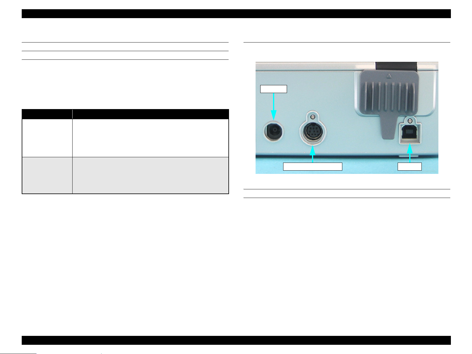
1.4 Interface
The interfaces of this scanner are shown below.
AC Input
TPU Unit Connector
Figure 1-1. Interface
USB INTERFACE
Interface type Universal Serial Bus Specification Revision 2.0
USB2.0
Ven
Prod
dor ID: 04B8h
uct ID: 0119h
Connector type One self-powered receptacle, Type B. Must be
connected directly to the host or to tier 1 in a hub
with a recommended USB cable.
PRODUCT DESCRIPTION Detailed Specifications 12
Page 13
EPSON Perfection 4490 Photo Revision A
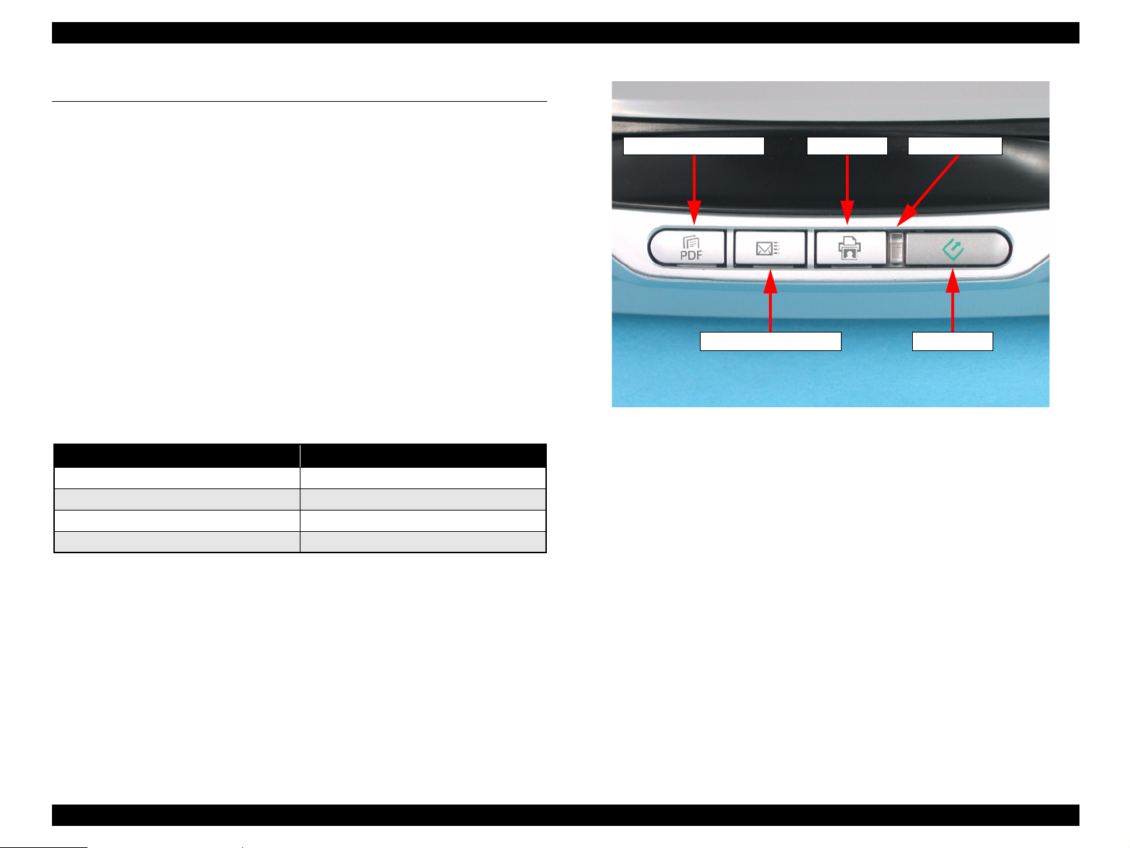
1.5 Exterior Specifications
1.5.1 Explanation of Switches
Start Button
Starts the EPSON Smart Panel.
Copy
Button
Prints photos and makes prints from films.
S
can to E-mail Button
Sends the scanned image by an e-mail.
Scan
to PDF Button
Starts scanning and stores the sccanned data.
1.5.2 Explanation of LED Indicators
Status LED
Located to the left of the Start Button. Indicates
light as shown in the table below.
LED Indication Status
Lit Green
Flashing green slowly Busy
Flashing red fast Error
Off Operate off:
Note *1: Warm up, scanning, initializing, etc.
Certain error conditions, such as Option Error, may not cause the Status LED to turn
*2:
red.
scanner statuses with a green or red
Ready
Scan to PDF Button
Scan to E-mail Button
Copy Button
Status LED
Start Button
Figure 1-2. Switches and LEDs
*1
*2
PRODUCT DESCRIPTION Exterior Specifications 13
Page 14
EPSON Perfection 4490 Photo Revision A
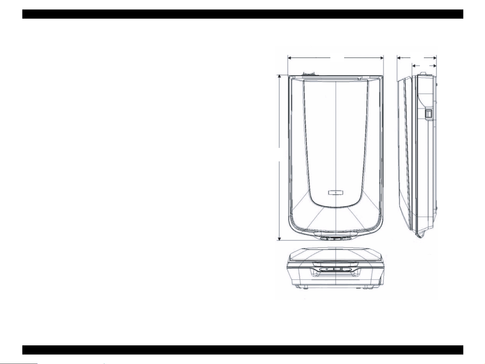
1.5.3 Dimensions
Dimensions and Weight
Dim
Weig
ensions 272 x 475 x 113mm (W x D x H)
ht Approx. 4.0 kg (without AC adaptor)
4.113 kg (with AC adaptor)
External Drawing
475
272
113
70
Unit: mm
Figure 1-3. External Dimensi
ons of Perfection 4490 Photo
PRODUCT DESCRIPTION Exterior Specifications 14
Page 15
EPSON Perfection 4490 Photo Revision A
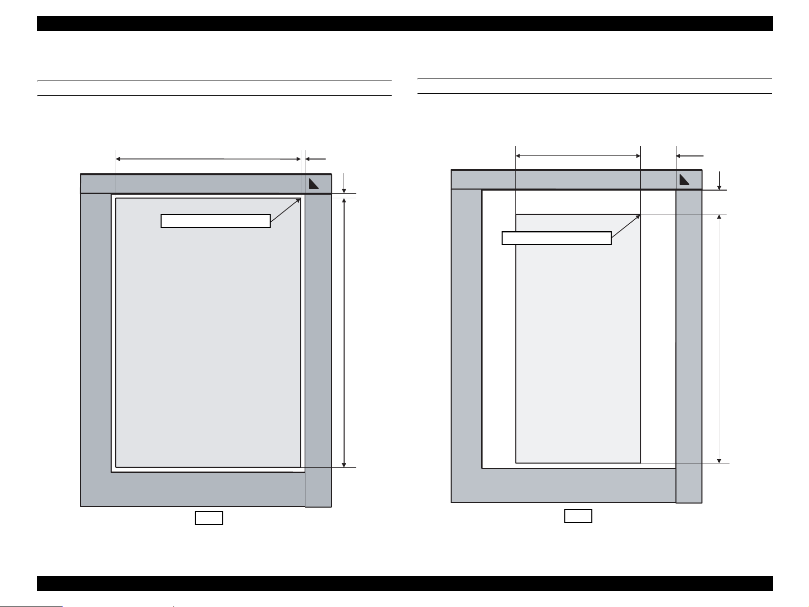
1.5.4 Maximum Document Size and Placement
REFLECTIVE DOCUMENT
Size : 8.5 in (216 mm) W x 11.7 in (297 mm) H
8.5 in (216 mm) 1 ± 0.5 mm
Scanning home position
1.6 ± 0.5 mm
11.7 in (297 mm)
TRANSPARENT DOCUMENT
Size : 2.72 in (68 mm) W x 9.44 in (236 mm) H
67.56 ± 1.5 mm
2.72 in (68 mm)
13.48 ± 1.5 mm
Scanning home position
9.44 in (236 mm)
Front
Figure 1-4. Reflective Document Scanning Range
Figure 1-5. Transparent Docu
Front
ment Scanning Range
PRODUCT DESCRIPTION Exterior Specifications 15
Page 16
EPSON Perfection 4490 Photo Revision A
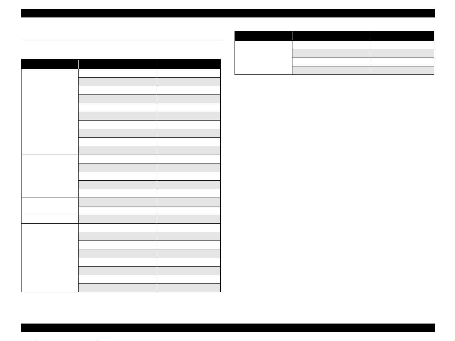
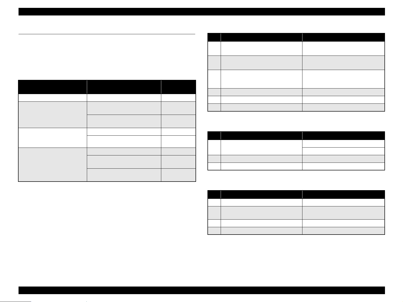
1.6 Control Codes
The following table is the list of control codes by the scanner.
Category Command Name Code
Execution command ID request
Status request ESC F
Extended status request
Status setting request ESC S
Scan start
Push button status request ESC !
Extended ID request
Scanner status request FS F
Scanning parameter request
New scan start FS G
Data form setting Data format setting ESC D i
Resolution setting ESC R n1 n2
Scanning area setting
Color setting ESC C i
Parameter setting
Correction Processing Gamma correction setting ESC Z i
Gamma correction table setting
Image Processing Threshold value setting ESC t I
Support and
Miscellaneous
Scan mode setting ESC g i
Initialization ESC @
Line counter setting
Option control ESC e i
Film type designation
Paper exit FF
Paper loading
Warm-up cancel ESC w
ESC I
ESC f
ESC G
FS I
FS S
ESC A n1 n2 n3 n4
FS W
ESC z i d [256]
ESC d i
ESC N i
PF
Category Command Name Code
Control Normal response ACK
Abnormal response NACK
Scanning stop
Header STX
CAN
PRODUCT DESCRIPTION Control Codes 16
Page 17

EPSON Perfection 4490 Photo Revision A
1.7 Error-Time Processing
Table 1-1. Error Definition and Remedy List
Category LED Indication Cause Scanner response Recovery
Command error None An invalid command or invalid
parameter was detected.
Fatal error Red LED flashes rapidly • The lamp is burnt out.
• The main unit is faulty.
• Firmware downloading failed.
command
• The scanner (interpreter) ignores the
incorrect command or parameter. Current
setting maintained.
• The Scanner (interpreter) returns NACK,
and waits for the next command parameter.
• The Scanner turns the carriage lamp off and
stops the operation.
• The Scanner sets Bit 7 of the status bit.
The error condition is cleared when the scanner
(interpreter) receives a valid command.
Turn the scanner off and then back on.
PRODUCT DESCRIPTION Error-Time Processing 17
Page 18

OPERATING PRINCIPLES
CHAPTER
2
Page 19
EPSON Perfection 4490 Photo Revision A
2.1 Engine Operation Outline
This section explains the functions and operating principles of the Perfection 4490
Photo Engine. The Engine is roughly divided into the Carriage Unit and Carriage
Moving Mechanism.
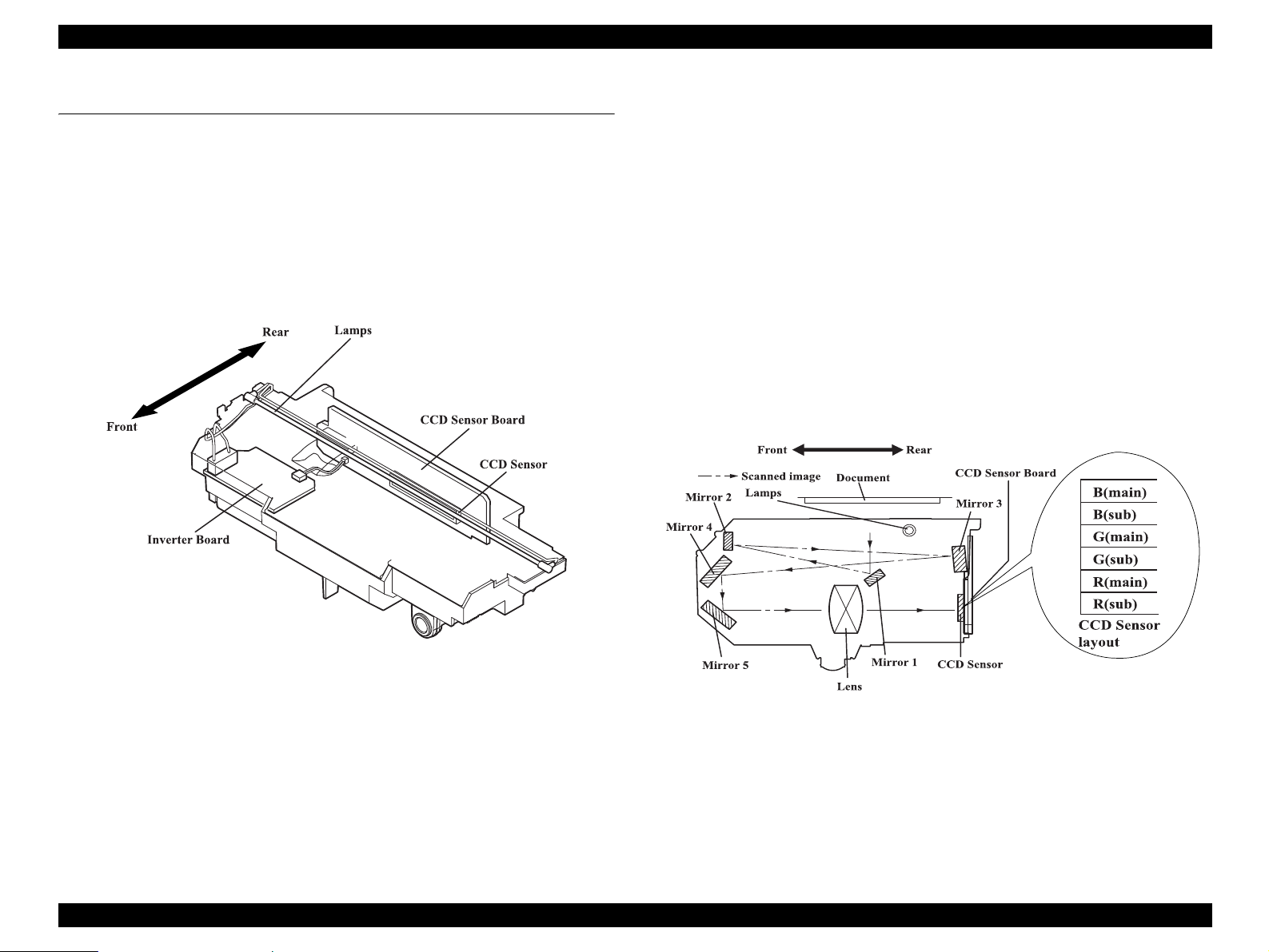
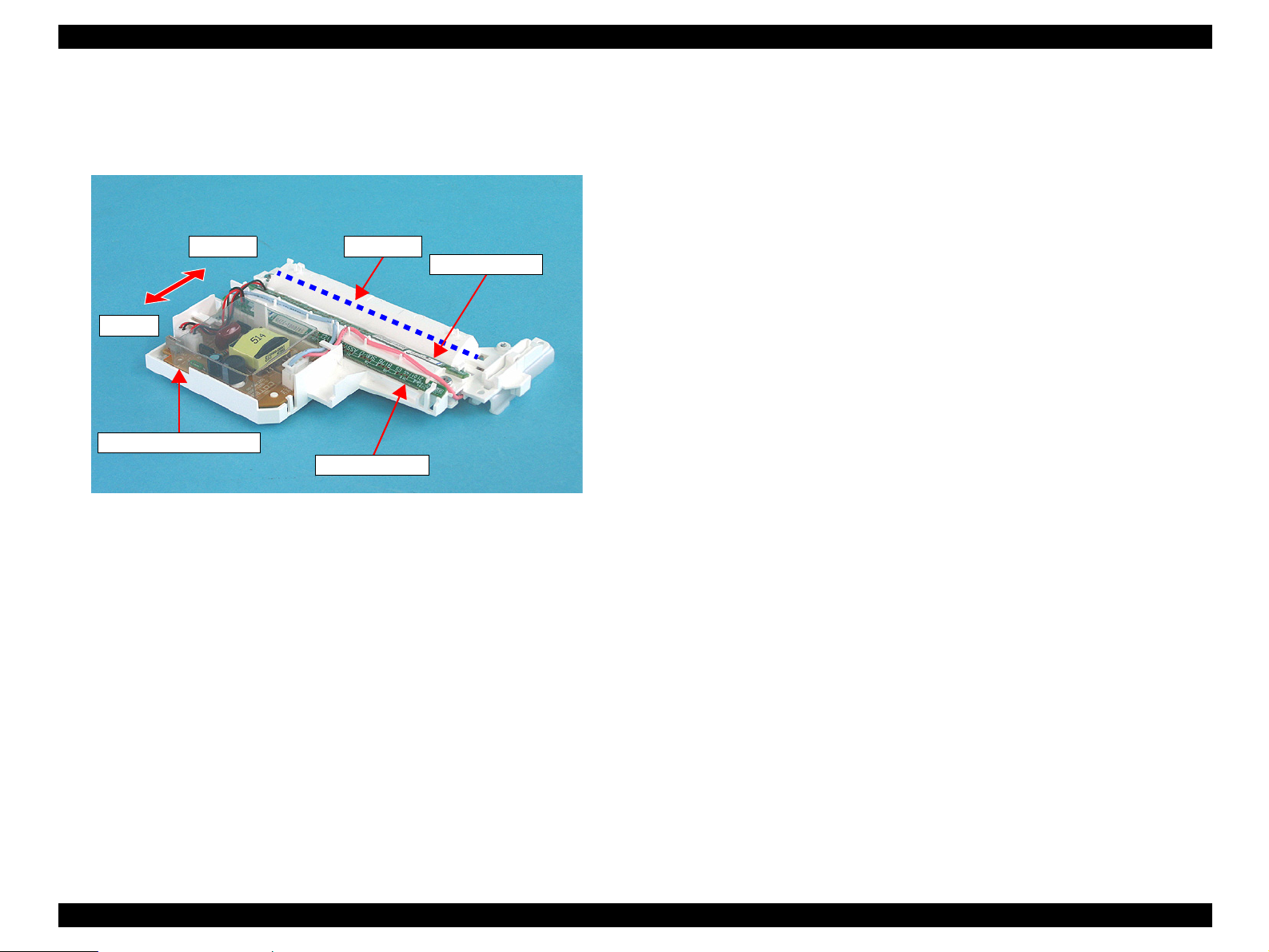
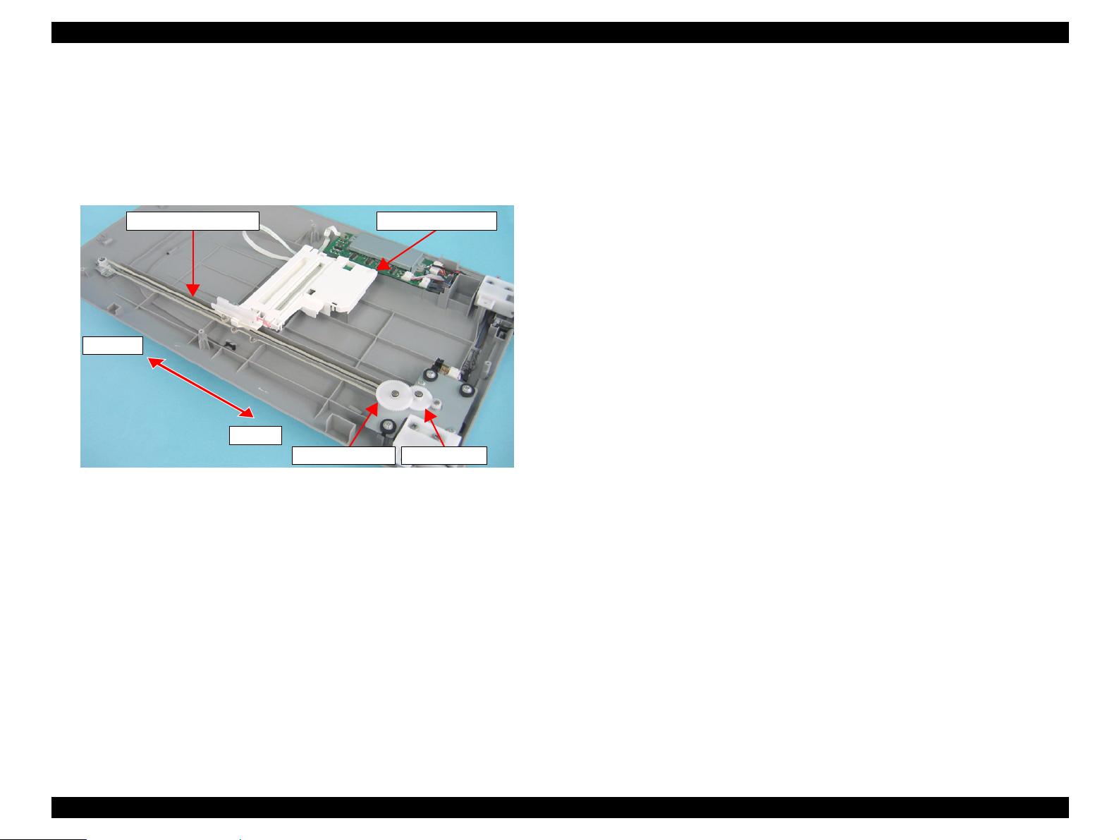
2.1.1 Carriage Unit outline
The Carriage Unit can be divided into the CCD Sensor Board, Inverter Board, Lamps
(light source), and Mirror/Lens Mechanism. (Refer to Fugure 2-1, 2-2.)
CCD
Inverter
Lamp
Mirror/Lens Mechanism
Sensor Board Forms an alternative six-lines color CCD (R, G, B
Board Boosts +24VDC and converts DC to AC to generate
s White cool cathode fluorescent lamps are used as a
independent) and its control and drive circuits.
the voltage for driving the Lamps (white cool cathode
fluorescent lamps).
light source. When the amount of light is not stable, the
Panel LED flashes and enter the standby mode until it
becomes stable.
The beam applied to the scanned document is reflected,
passes through the Mirror/Lens Mechanism in the
Carriage Unit for correction of the beam axis, and then
reaches the CCD Sensor. The light components R, G, B
are extracted by the Color CCD Sensor itself, not by
switching between R, G and B of the light source as
previously.
Figure 2-1. Carriage Unit Configuration
Figure 2-2. Mirror/Lens Mechanism
OPERATING PRINCIPLES Engine Operation Outline 19
Page 20
EPSON Perfection 4490 Photo Revision A
2.1.2 TPU Carriage Unit Outline
The TPU Carriage Unit consists of TPU Inverter Board, Lamps (light source), SUB_C
Board, and SUB_D Board. (Refer to Fugure 2-3.)
Front
Rear
TPU Inverter Board
Figure 2-3. TPU Carriage Unit Configuration
Inverter Board
necessary to power the Lamps.
Lamps used as
the light output becomes unstable, the Panel LED flashes and the scanner enters
standby mode until it becomes stable.
SUB_C Board and SUB_D Board each
converts DC to AC and boosts the voltage to generate the current
the primary light source are white cool-cathode fluorescent lamps. If
Lamps
SUB_C Board
SUB_D Board
contain LEDs to generate infrared light.
OPERATING PRINCIPLES Engine Operation Outline 20
Page 21
EPSON Perfection 4490 Photo Revision A
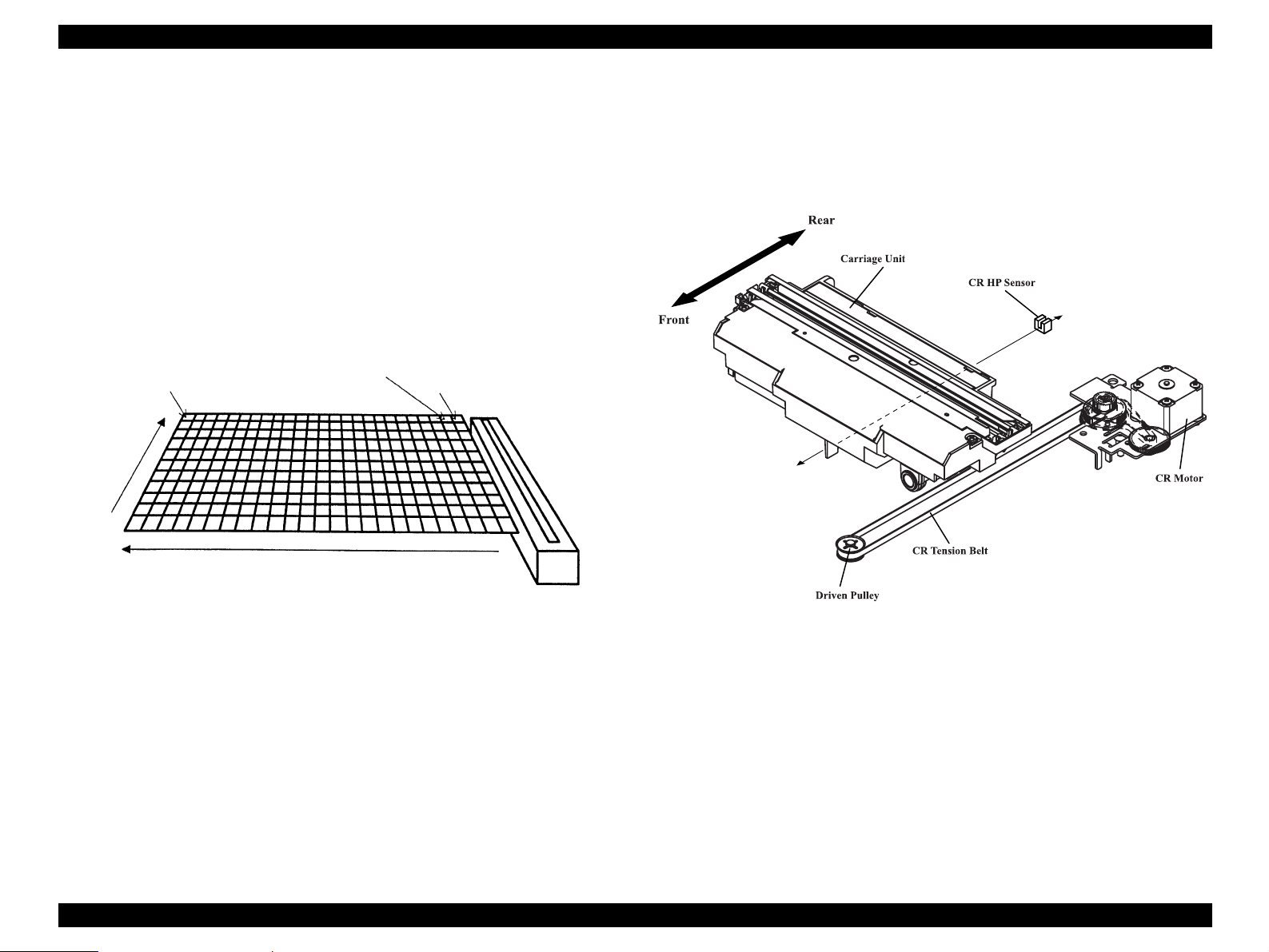
2.1.3 Carriage Moving Mechanism Operation
The image data of a document are scanned in the combination of the main scanning
direction (one line: CCD Sensor) and sub scanning direction (multiple lines: Carriage
Unit movement). (Refer to Fugure 2-4.)
The line type color CCD Sensor can only scan t
direction (in parallel with the Carriage Unit) at one time. To scan the data of the second
and latter lines in the sub scanning direction, the Carriage Unit having a built-in CCD
Sensor is moved by CR drive. The scanned data are sent to the Control Board. The
scanning of Line n data and the processing of Line n-1 image data are performed
consecutively at the same time.
1 pixel
Document
Main
scanning
he data of one line in the main scanning
Second line
First line
The Carriage Unit slides along the guide rail in the sub scanning direction. To perform
is sliding operation, the CR (Carriage) Motor transmits its drive power to the Timing
th
Belt, which is fixed to the Carriage Unit, via the Drive Pulley and Deceleration Gear.
The image data scanning start position is determined by the CR HP Sensor located on
the Control Board. A stepping motor used as the CR Motor is driven under open loop
control. (Refer to Fugure 2-5.)
Sub scanning (by Carriage movement)
Scanner Head
(Carriage)
Figure 2-5. Carriage Operation
Figure 2-4. Carriage Movement
OPERATING PRINCIPLES Engine Operation Outline 21
Page 22
EPSON Perfection 4490 Photo Revision A
2.1.4 TPU Carriage Drive Mechanism Operation
The TPU Carriage Unit slides along the guide shaft in the secondary scanning direction
as the TPU CR (Carriage) Motor transmits its drive power to the TPU CR Drive Belt
connected to the TPU Carriage Unit, via the Idle Pulley and Drive Pulley. (Refer to
Fugure 2-6.) The TPU CR Motor uses a stepper motor and is driven under open loop
control.
TPU CR Drive Belt TPU Carriage Unit
Front
Rear
Drive Pulley Idle Pulley
Figure 2-6. TPU Carriage Operation
OPERATING PRINCIPLES Engine Operation Outline 22
Page 23
EPSON Perfection 4490 Photo Revision A
2.2 Digital ICE Function Operation
This scanner features Digital ICE for Film, an image correction process that uses a
combination of hardware and software to detect and eliminate physical flaws, dust or
dirt, either on the Film or the scanner itself. (Film includes color or monochrome
negative, and color positive.)
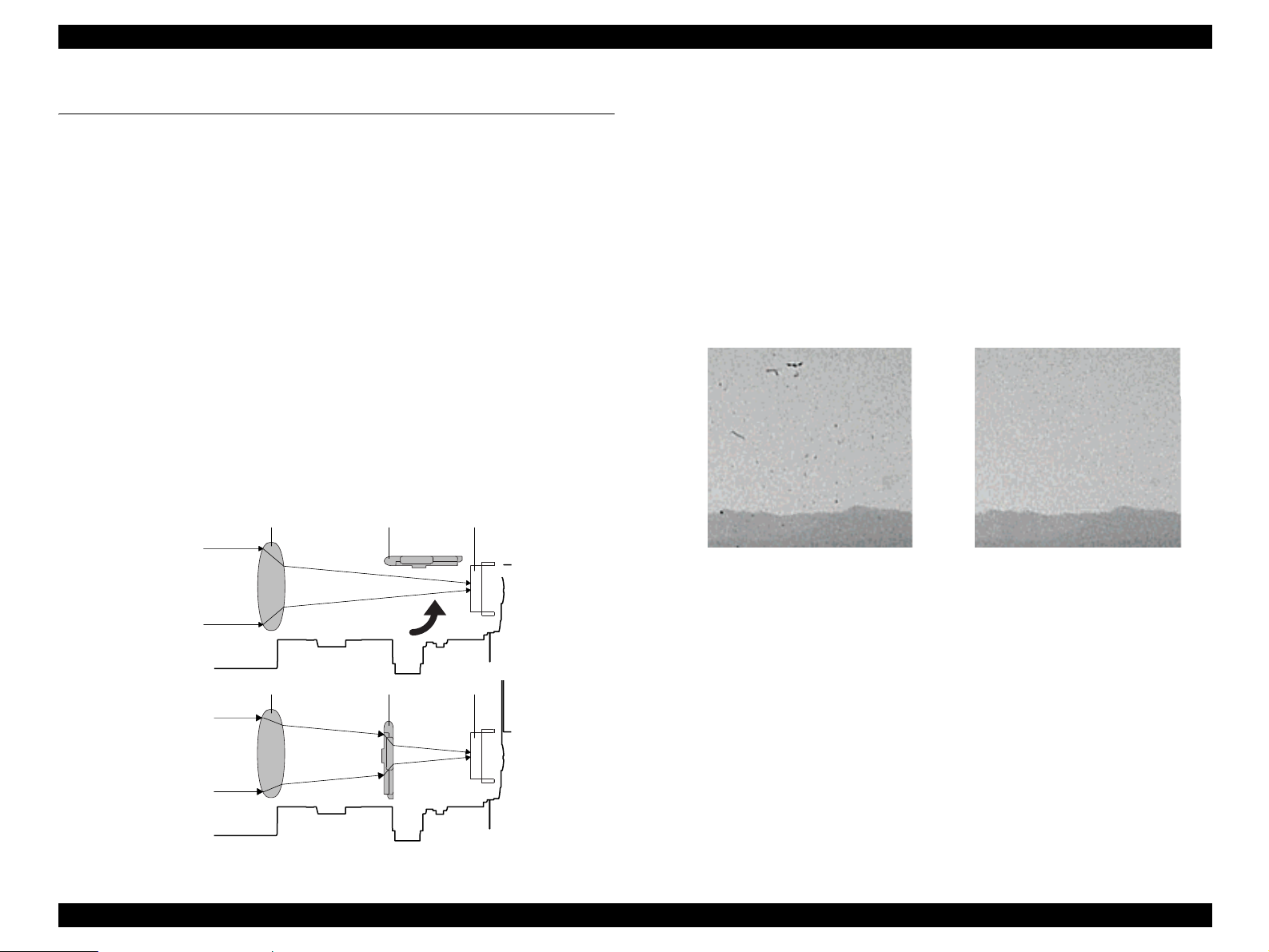
2.2.1 Digital ICE for Film Overview
Because of its longer wavelength, infrared light normally passes completely through
film media, such as negatives or slides, during a scan. Physical flaws or dust, however,
do block infrared light. When a film document with dust or physical flaws is scanned
using infrared light, the light is physically blocked by the flaw or dust, and the resulting
image clearly shows only the dust and/or flaws present. By superimposing the images
scanned with infrared light and visible light, the Film-ICE software is able to detect the
inconsistency in the digitized data caused by the flaw and automatically remove it
using interpolated image data to overwrite and correct the image. Because of the
difference in wavelength between infrared light and visible light, a secondary lens
("Glass Plate" in the images below) must be employed during the Film-ICE visiblelight scan to compensate for the resulting difference in the size of the images so that
they can be superimposed accurately. The Glass Plate is moved into and out of position
by a solenoid.
Lens CCDGlass Plate
Digita
1. Read the visible light position. Two holes in the upper housing are scanned with
2. Move the secondary lens (Glass Plate) into posi
3. Retract the secondary lens and scan the film
4. Electronically superimpose the images obt
5. Replace the "flaw" image data with image data interpolated
l ICE for Film Process Sequence
vi
sible light in order to register the home position of image being scanned.
tion and scan the film in visible-
light.
in infrared-light.
ained from each light source and
identify the physical flaws and/or foreign matter.
from adjacent areas.
Dirt on the Slide After Correction
Infrared Light
Lens CCDGlass Plate
Visible Light
Figure 2-7. Refraction of Infrared Light and Visible Light
Figure 2-8. Extraction/Correction of
Dust by Film-ICE Function
OPERATING PRINCIPLES Digital ICE Function Operation 23
Page 24
EPSON Perfection 4490 Photo Revision A
2.3 Operation Principle of Electric Circuit
The following electric circuits are used in the scanner.
Main Board
Table 2-1. Main Board IC
Name Location Details
S1R77001F00A2 IC4 ASIC: Host base scanner controller
S1R720G0F00A0 IC6 ASIC: UTM (USB2.0 interface)
EDS6416AHTA-75-E IC3
TB62205F IC1
AP1120SLA IC2
M74HC595AM13TR IC5 Serial-Parallel converter
CCD Board
Table 2-2. CCD Board IC
Name Location Details
ILX580K IC1 CCD
AK8415 IC4 16bit A/D converter
E02A41YA IC5
SN74ACT244NSR IC2, IC3 CCD drive buffer
KIA78M05F-RTF/P IC6
Pan
el Board
This board has four buttons (Start/Copy/Scan to E-mail/Scan to PDF) and LED
lamp.
SDRAM 1M x16bit x4bank
Motor Driver + DC-DC converter CR Motor Drive
+24V IN, +12V/+5V OUT
DC-DC converter
+5V IN, +3.3V/+2.5V OUT
ASIC: CCD/AFE drive signal generator
DC-DC converter
+12V IN, +5V OUT
Power supply
canner is powered with 24 VDC voltage from the AC adapter.
The s
AC adap
• Rated output DC24 1.1A
• Input Voltage AC100-120V ± 15% (100V)
ter rated voltage
AC220-240V ± 10% (200V)
• Rated Input Current 0.7A (AC 100V system)
0.4A (AC 200V system)
• Input Frequency Range 50 to 60Hz ± 0.3Hz
• Output Voltage DC24 to 26.4V
The 24 VDC voltage is supplied to CN4 on the Main Board. A
between the DC jack and the Main Board.
DRV
Board (TPU Unit)
Table 2-3. DRV Board IC
Name Location Details
M74HC595RM13TR IC1, IC2 8bit Shift Register
LB11847L-E IC3 TPU CR Motor Driver
CD74HC75M96 IC5 Lamp/LED controller
AD
F Board (Option)
Table 2-4. ADF Board IC
Name Location Details
M54670P IC2 ADF Motor driver
MM74HC165M IC3 Parallel-Serial Converter
M66311FP-250D IC1
MM74HCT04M IC4 Buffer IC
Serial-Parallel Converter
power switch is located
OPERATING PRINCIPLES Operation Principle of Electric Circuit 24
Page 25

TROUBLESHOOTING
CHAPTER
3
Page 26
EPSON Perfection 4490 Photo Revision A
3.1 Overview
This chapter explains the remedies for errors detected by the scanner’s self-diagnostic
function, and provides a troubleshooting guide based on observed ploblems.
3.1.1 Self-Diagnosing
This scanner has a self-diagnostic function that automatically diagnoses the operating
status of major components, and uses an LED indication to show the error status. This
function detects the following error statuses shown in the table below. The corrective
action is also listed.
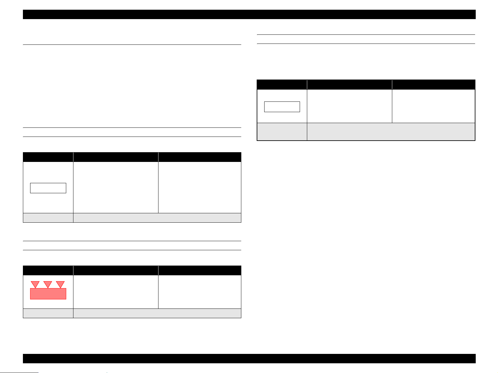
COMMAND ERROR
Table 3-1. Command Error
LED Indication Cause Disposition
• Unidentifed command is
detected.
(None)
Recovery The error condition is canceled upon receipt of a valid command.
• T he scanner (interpreter)
ignores the incorrect command
or parameter. The current
settings are maintained.
• Scanner (interpreter) returns
NACK, and waits for the next
command or parameter.
OPTION ERROR
(Only when the Option Unit is fitted and the scanner is ready to operate under the
control command (ESC e))
Table 3-3. Option Error
LED Indication Cause Disposition
• T he cover is open.
• Document is not loaded.
(None)
Recovery Remove the error cause to recover.
Receivable command [ESC F, ESC f, ESC @]
• The Scanner sets Bit 7 of the
status bit.
FATAL ERROR
Table 3-2. Fatal error
LED Indication Cause Disposition
• The lamp is burnt out.
• The main unit is faulty.
• Firmware downloading failed.
(Rapid flashing, red)
Recovery Turn the scanner off and then back on.
• T he Scanner turns the carriage
lamp off and stops the operation.
• T he Scanner sets Bit 7 of the
status bit.
TROUBLESHOOTING Overview 26
Page 27
EPSON Perfection 4490 Photo Revision A
3.2 Troubleshooting
This section provides troubleshooting procedures based on observed faults.
Refer to Tab
the table, find the Problem that most closely matches what you observe and follow the
procedures given in the table cross referenced in the right-hand column.
Scanned image quality error. Scanned image is not clear.
The main unit does not operate
when powered-on.
Fatal error. (The LED flashes red.)
Recovery cannot be made when
power is switched on again.
The TPU does not work at all. The TPU does not operate. 3-10
le 3-4, and choose the table describes the general fault indication. Within
Table 3-4. Trouble Phenomenon, Cause and Troubleshooting Table
Problem Definition
Troubleshooting
Table
3-5
The Main Unit does not perform
initialization operation.
The host does not recognize the
scanner when power is switched on.
The Carriage Unit does not operate. 3-8
The Fluorescent Lamps are not lit.
The TPU Carriage Unit does not
operate.
The Fluorescent Lamps of the TPU do
not light up.
3-6
3-7
3-9
3-11
3-12
Table 3-5. Scanned Image Quality Error.
Step Possible Cause Corrective Action
The Document Glass is not clean. (Image
1
has white spots)
The mirror in the Carriage is not clean.
2
(Vertical bands appear on the image.)
Upper Housing failure
3
(
The white document mat is deformed or is
not clean.)
4 CCD Sensor Board failure Replace the Carriage Unit.
5 Main Board failure
6 Carriage mechanism failure Replace the Carriage mechanism.
Clean the glass.
(Refer to 6.1.1 Cleaning)
Clean the mirror.
(Refer to 6.1.1 Cleaning)
Replace the Upper Housing.
Replace the Main Board
Table 3-6. The Main Unit does not perform initialization operation.
Step Possible Cause Corrective Action
There are some connectors that are not
1
connected correctly
2 CR Motor failure Replace the CR Motor.
3 Main Board failure Replace the Main Board
Connect them correctly.
Replace the Main Board
Table 3-7. The host does not recognize the scanner when power is switched on.
Step Possible Cause Corrective Action
1 The host computer does not support USB.
The TWAIN Driver supplied with the
2
scanner has not been installed correctly.
3 The USB cable is damaged.
4 Main Board failure Replace the Main Board
Replace or modify the host computer.
Install (reinstall) the TWAIN Driver for the
Perfection 4490 Photo.
Replace the USB cable.
TROUBLESHOOTING Troubleshooting 27
Page 28

EPSON Perfection 4490 Photo Revision A
Table 3-8. The Carriage Unit does not operate.
Step Possible Cause Corrective Action
1 The Carriage Lock has not been released.
2
The Upper Housing is not installed corr ectly.
Connector CN1 on the Main Board is not
3
conn
ected.
4
The Carriage FFC is not connected correctly.
Carriage Mechanism failure
5
Release the Carriage Lock.
Install it normally.
Connect it correctly.
Connect the FFC correctly.
Replace the Main Board
Does the CR Motor operate normally?
↓
Yes
→ Disassemble and reassemble the
scanner, or replace the corresponding part(s).
No → Replace the CR Motor.
Table 3-9. The Fluorescent Lamps are not lit.
Step Possible Cause Corrective Action
Connector CN1 on the Main Board is not
ected.
conn
1
Connector CN1 and CN2 on the CCD
Board are not connected.
The lamp is not set on the Inverter Board
2
correctly.
Carriage Unit failure ( The Carriage FFC is
3
4 Main Board failure Replace the Main Board
nected to the Main Board and the
not con
Carriage.)
Connect the disconnected connectors.
Set the lamp on the board correctly.
Replace the Carriage Unit.
Table 3-10. The TPU does not operate.
Step Possible Cause Corrective Action
The TPU Unit Cable is not connected to the
1
in unit.
ma
Connector CN5 is not connected to the
2
Main Board.
3 Main Board failure
Connect the Cable to the main unit.
Connect it correctly.
Replace the Main Board
Table 3-11. The TPU Carriage Unit does not operate.
Step Possible Cause Corrective Action
The TPU Unit Cable is not connected to the
1
ma
in unit.
The TPU Carriage Lock has not been
2
released.
The TPU Lower Housing
3
correctly.
The three torsion springs are not
attached to the TPU CR Drive Belt
correctly.
• The TPU CR Motor does not
4
5 TPU CR Motor failure Replace the TPU CR Motor.
6 DRV Board failure Replace the DRV Board.
7 Main Board failure Replace the Main Board
move normally when poweredon with the TPU Lower Housing
removed.
• The TPU Carriage Unit does not
move normally with the TPU CR
Motor removed.
The TPU Carriage Mechanism
Failure.
is not installed
Connect the TPU Cable to the main unit.
Release the TPU Carriage Lock.
Reinstall it correctly.
Attach them to the belt correctly.
Replace the TPU Carriage Unit.
Table 3-12. The Fluorescent Lamps of the TPU do not light up
Step Possible Cause Corrective Action
The DRV Inverter FFC is not connected to
1
N1 on the TPU Inverter Board and CN3
C
on the DRV Inverter Board.
CN2, CN3, and CN4 on the TPU Inverter
2
Board are not connected.
Failure of the SUB_C Board and the
3
SUB_D Board
4 DRV Board failure Replace the DRV Board.
5 Main Board failure
Connect the FFC to CN1 and CN3
Connectors.
Connect the connectors.
Replace the SUB_C Board and the SUB_D
Board.
Replace the Main Board
TROUBLESHOOTING Troubleshooting 28
Page 29

DISASSEMBLY / ASSEMBLY
CHAPTER
4
Page 30
EPSON Perfection 4490 Photo Revision A
4.1 Overview
This chapter explains the procedures for disassembling the major units and parts of the
product. Unless otherwise explained, reassembly should be carried out in the reverse
order of the disassembly procedure. When you have to remove any parts or
components that are not described in this chapter, refer to the exploded diagram in the
Appendix.
Before starting disassembly, always read the
4.1.1 Precautions
Before starting the disassembly or reassembly of the product, read the following
precautions given under the headings WARNING and CAUTION.
W A R N I N G
C A U T I O N
Before disassembling or reassembling this product, always
disconnect the Power Cable and Interface Cable. When you
have to work with power on for voltage measurement, etc., use
extreme care not to get an electric shock and do the work in
accordance with the procedures given in this manual.
To prevent your hands from being cut by sharp edges, always
wear gloves before starting disassembly or reassembly.
When touching any internal components, use static electricity
discharge equipment such as anti-static wrist straps.
Provide sufficient work space for disassembling and
reassembling.
Always use only the recommended tools for disassembly,
reassembly and adjustment.
Be sure to tighten the screws to the specified torque.
Use the specified grease for lubrication. Refer to Chapter 6 for
details.
Since a prototype was used to illustrate these disassembly and
assembly procedures, the appearance of some parts may differ
from those on an actual product. The procedures themselves,
however, are accurate for the retail model.
precautions described in the next section.
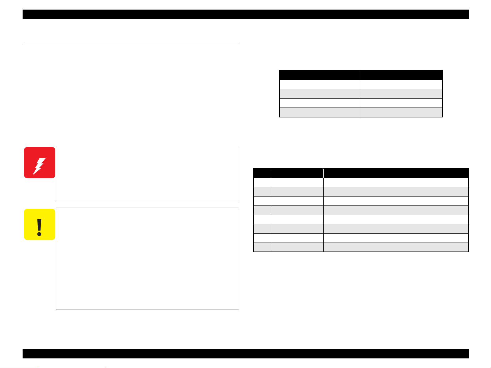
4.1.2 Recommended Tools
To protect this product from damage, use the tools indicated in the following table.
Table 4-1. Specified Tools
Name Epson Part Number
Phillips screwdriver, No. 2
Flat-blade screwdriver 1080527
Tweezers
Long-nose pliers 1080561
1080532
1080561
4.1.3 Recommended Screws
The following table indicates the screws used in the EPSON Perfection 4490 Photo
Scanner.
Table 4-2. Recommended Screws
No. Name Type
1 C.B.P. 3 x 6
2 C.B.P. 3 x 8 Phil lips Bind P-tit e Screw, size M3, 8 mm length
3 C.B.P. 3 x 12
4 C.P. 3 x 8 Phillips Pan Head Screw, size M3, 4 mm length
5 C.B. 3 x 3
6 C.B.P. 4 x 12 Phillips Bind P-tite Screw, size M3, 8 mm length
7 C.B.S. 3 x 5
8 C.P.F.P. 3 x 8 Phillips Pan Flange Head P-tite Screw, size M3, 8 mm length
Phillips Bind P-tite Screw, size M3, 8 mm length
Phillips Bind P-tite Screw, size M3, 8 mm length
Phillips Bind Screw, size M3, 3 mm length
Phillips Bind S-tite Screw, size M3, 5 mm length
Disassembly / Assembly Overview 30
Page 31

EPSON Perfection 4490 Photo Revision A
4.2 Disassembly Procedure
This section illustrates how to remove the main components of this product. Unless otherwise specified, the reassembly procedure is the reverse of the disassembly procedure. For
additional assembly illustrations, refer to the exploded diagrams in the Appendix.
The following flowchart shows the disassembly procedure step-by-step,
Start
Removing the TPU Unit(P.32)
Removing TPU Lower
Housing(P.45)
Removing Torsion Spring(P.49)
Removing the TPU Carriage
Unit(P.50)
Removing the Upper
Housing(P.33)
Removing the Panel Board(P.36) Removing the Main Board(P.37)
Removing the Power
Switch(P.40)
Removing the DRV Board(P.48) Removing the Hinge Assy.(P.46)
and the section and page number where the procedure is described.
Removing the Carriage
Unit(P.34)
Removing the Driven Pulley, Driven
Pulley Spring, and the Driven Pulley
Holder Assy.(P.42)
Removing the Panel FFC(P.41)
Removing the TPU Unit
Cable(P.47)
Removing the CR Motor Unit, Motor
Tension Belt, and the CR Tension
Belt(P.43)
Removing the Sensor
Board(P.46)
Removing the TPU Inverter
Board(P.51)
Removing the SUB_C Board,
SUB_D Board, and the
Lamp(P.53)
Removing the TPU CR
Motor(P.55)
Figure 4-1. Disassembly Flowchart
Disassembly / Assembly Disassembly Procedure 31
Page 32

EPSON Perfection 4490 Photo Revision A
4.2.1 Removing the TPU Unit
1. Disconnect the TPU Unit cable from the Main Unit.
Main
TPU Unit Cable
Figure 4-2. Removing the TPU Unit (1)
2. Open the TPU Unit.
3. Hold both ends of the TPU Unit and then lift and remove it.
TPU Unit
3
2
Figure 4-3. Removing the TPU Unit (2)
Disassembly / Assembly Disassembly Procedure 32
Page 33

EPSON Perfection 4490 Photo Revision A
4.2.2 Removing the Upper Housing
1. Remo ve the TPU Unit. See Section 4.2.1 on page 32.
2. Remove the four C.B.P. M3 x 8 screws that secure the Upper Housing to remove
it.
Upper Housing
C.B.P. 3 x 8
(7±1 kgf.cm)
Viewed from the outside
Figure 4-4. Removing the Upper Housing
Disassembly / Assembly Disassembly Procedure 33
Page 34

EPSON Perfection 4490 Photo Revision A
4.2.3 Removing the Carriage Unit
1. Release the Carriage Lock at the rear of the main unit.
Unlock
Carriage Lock
Figure 4-5. Releasing the Carriage Lock
2. Remove the Upper Housing. See Section 4.2.2 on page 33.
3. Move the Carriage Unit to the front of the main unit.
Lock
Carriage Unit
4. Disconnect the Carriage FFC from the Main Board. See Section 4.2.5 Step 5 - Step 7
5. Remove the two-sided tape that secure the Carriage FFC to the Upper Housing.
6. Rem ove the Ferrite Core from the Carriage FFC.
Lower Housing
Tape Position
Carriage FFC
Ferrite Core
Figure 4-7. Removing the Carriage FFC
Secure the Carriage FFC with a piece of two-sided tape at the
position shown in Figure 4-7
3
Figure 4-6. Moving the Carriage Unit
.
Disassembly / Assembly Disassembly Procedure 34
Page 35

EPSON Perfection 4490 Photo Revision A
7. Move th e A part on the Driv en Pulley Holder Assy. in the direction of the arrow
and remove the CR Tension Belt from the Driven Pulley.
A part
Driven Pulley
CR Tension Belt
Figure 4-8. Removing the CR Tension Belt
8. Hold the Carriage Unit and release one end
bushing of the Lower Housing, then pull the other end out of the front bushing of
the Lower Housing.
9. Remo ve the Carriage Shaft from the Carriage Unit.
8-1
Driven Pulley Holder Assy.
of the Carriage Shaft from the rear
Carriage Unit
Carriage Shaft
10. Push up the B part of the Lock Plate attached on the rear of the Carriage Unit to
re
move the Lock Plate from the Carriage Unit.
Lock Plate
B part
Figure 4-10. Removing
the Carriage Unit
Rear
Bushing
Front
Bushig
8-2
Figure 4-9. Removing the Carriage Shaft
Disassembly / Assembly Disassembly Procedure 35
Page 36

EPSON Perfection 4490 Photo Revision A
4.2.4 Removing the Panel Board
1. Remo ve the Carriage Unit. See Section 4.2.3 on page 34.
2. Pull the ground terminal out of the front bushing of the Lower Housing.
3. Lift the Panel Board and disconnect the Panel FFC Connector CN1, then remove
the Panel Board.
Notch
Front Bushing
Positioning Holes
Notch
CN1
Ground Cable
2
Panel Board
When reinstalling the Panel Board, pay attention to the followings.
Pu t the ground terminal into the front bushing of the Lower
Housing as shown in Figure 4-11
Route the ground cable through the notches as shown in Figure
4-11.
Insert the two constricted parts on both left and right ends of
the Panel Board into the tabs of the Lower Housing and match
the three notches of the board with the three tabs of the Lower
Housing as shown in Figure 4-11
.
.
3
Constricted Parts and Tabs
Figure 4-11. Removing the Panel Board
Disassembly / Assembly Disassembly Procedure 36
Page 37

EPSON Perfection 4490 Photo Revision A
4.2.5 Removing the Main Board
1. Release the Carriage Lock. See Section 4.2.3 Step 1
2. Remove the Upper Housing. See Section 4.2.2 on page 33.
3. Move the Carriage Unit to the front of the main unit. See Section 4.2.3 Step 3
4. Remo ve the Carriage Lock from the Lower Housing.
Carriage Lock
Figure 4-12. Removing the Carriage Lock
5. Remove the Main Board Cover in the following procedure.
1. Rem ove the C.B.P. M3 x 8 screw and C.B.P. M3 x 12 screws that secure the
Main Board Cover.
2. Remove the two C.B.P. M3 x 8 screw that secure the Main Board from the
rear of the main unit.
C.B.P. 3 x 8
(4±1 kgf.cm)
Rear of the Main Unit
C.B.P. 3 x 12
(6.5±0.5 kgf.cm)
C.B.P. 3 x 8
(6.5±0.5 kgf.cm)
Main Board Cover
Figure 4-13. Removing the Main Board Cover (1)
Disassembly / Assembly Disassembly Procedure 37
Page 38

EPSON Perfection 4490 Photo Revision A
3. Release the tab of the Main Board Cover with a flat-blade screwdriver and lift
one side (tab side) of the Main Board Cover.
4. Slide the Main Board Cover in the direction of the arrow to release it from the
two tabs and remove the Main Board Cover.
3-1
Tab
Main Board Cover
3-2
When reinstalling the Main Board Cover, match the two tabs and
two interfaces with the holes of the Main Board Cover as shown
below.
Tabs
I/F
Figure 4-15. Installing the Main Board Cover
4
Tab
Figure 4-14. Removing the Main Board Cover (2)
Disassembly / Assembly Disassembly Procedure 38
Page 39

EPSON Perfection 4490 Photo Revision A
6. Remove the four C.B.P. M3 x 8 screws that secure the Main Board.
7. Disconnect the all connectors on the Main
CN1: Carriage FFC
CN2: CR Motor Cable
CN3: Power Switch Connector
CN6: Panel FFC
C.B.P. 3 x 8
(7±1 kgf.cm)
CN1
Board and remove the Main Board.
CN2
CN3
CN6
Figure 4-16. Removing the Main Board
Main Board
Disassembly / Assembly Disassembly Procedure 39
Page 40

EPSON Perfection 4490 Photo Revision A
4.2.6 Removing the Power Switch
1. Move the Carriage Unit to the front of the main unit. See Section 4.2.3 Step 1 -
Step 3
2. Discon nect the Power Switch Conn ector CN3 from the Main Board. See Section
4.2.5 Step 5 - Step 7
3. Remove the Power Switch Connector Cable from the cable trench.
Power Switch Connector Cable
4. Push the Power Switch toward the ou tside whi le releasin g the two tabs, and
rem
ove the Power Switch by pushing it out through the hole on the Lower
Housing.
4-2
Power Switch
4-1
Tabs
Cable Trench
Figure 4-17. Removing the Po
When reinstalling the Power Switch, route the Power Switch
Connector Cable through the cable trench as shown in Figure
4-17.
wer Supply Cable Cover
4-1
Figure 4-18. Removing the Power Switch
Disassembly / Assembly Disassembly Procedure 40
Page 41

EPSON Perfection 4490 Photo Revision A
4.2.7 Removing the Panel FFC
1. Move the Carriage Unit to the front of the main unit. See Section 4.2.3 Step 1 -
Step 3
2. Discon nect the Panel FFC from the Main Board. See Section 4.2.5 Step 1 - Step 7
3. Move the Carriage Unit to its home position, and remove the two-si ded tape that
secure the Panel FFC.
4. Discon nect the Panel FFC from CN1 Connector on the Panel Board.
CN1
4
Panel Board
Carriage Unit
Wh en installing the Panel FFC, attach the Ferrite Core as
shown in the figure below.
Ferrite Core
Figure 4-20. Installing the Ferrite Core
Secure the Panel FFC with a piece of two-sided tape at the
position shown in Figure 4-19
.
3
Panel FFC
Tape Position
Figure 4-19. Removing the Panel FFC
Disassembly / Assembly Disassembly Procedure 41
Page 42

EPSON Perfection 4490 Photo Revision A
4.2.8 Removing the Driven Pulley, Driven Pulley Spring,
and the Driven Pulley Holder Assy.
1. Remo ve the Carriage Unit. See Section 4.2.3 on page 34.
2. Hold the A part of the Driven Pulley Holder Assy. and slide it in the direction of
the arrow to remove the assy. from the two tabs on the Lower Housing.
A part
Tabs
Driven Pulley Holder Assy.
Figure 4-21. Removing the Driven Pulley Holder Assy.
3. Remove the Driven Pulley Spring from the Driven Pulley Holder Assy.
4. Remove the washer and remove the Driven Pulley
Pulley Holder Assy.
Driven Pulley Spring
Figure 4-22. Removing the Driven Pulley and
from the shaft of the Driven
Washer
Driven Pulley
the Driven Pulley Spring
Disassembly / Assembly Disassembly Procedure 42
Page 43

EPSON Perfection 4490 Photo Revision A
4.2.9 Removing the CR Motor Unit, Motor Tension Belt, and the CR Tension Belt
1. Remo ve the Carriage Unit. See Section 4.2.3 on page 34.
2. Disconnect the CR Motor Connector CN2 from the Main Board. See Section 4.2.5
Step 1 - Step 5
3. Remove the two C.B.P. M3 x 8 screws that secure the CR Motor Unit and remove
it together with the ground plate.
CR Motor UnitPositioning Hole and Guide Pin
Install the ground plate in the following procedure.
1. Match the positioning hole of the ground plate with the guide
pin of the Lower Housing.
2. Place the CR Motor Unit as shown
secure the CR Motor Unit and the ground plate to the Lower
Housing.
When installing the CR Motor Unit, match the positioning hole
and the guidepin as shown in Figure 4-23
Route the CR Motor Cable through the tabs and slot as shown
in the figure below.
Positioning Hole and Guide Pin
Ground Plate
in the figure below and
.
C.B.P. 3 x 8
(7±1 kgf.cm)
Figure 4-23. Removing the CR Motor Unit
CN2
Ground Plate
Tabs and Slot
Figure 4-24. Routing the CR Motor Cable
Disassembly / Assembly Disassembly Procedure 43
Page 44

EPSON Perfection 4490 Photo Revision A
3. Remo ve the torsion spring and the C.B. M3 x 3 screw that secure the Tensioner,
and remove the Pulley.
A D J U S T M E N T
R E Q U I R E D
When installing the Tensioner, make sure to perform the Tensioner
Adjustment. See Section 5.1.2.1 on page 58.
4. Remove the Motor Tension Belt and the CR Tension Belt from the CR Motor Unit
in th
at order.
CR Tension Belt
Torsion Spring
C.B. 3 x 3
(6±1kgf.cm)
Tensioner
Pulley
Motor Tension Belt
Figure 4-25. Removing the Motor Tension Belt and the CR Tension Belt
Disassembly / Assembly Disassembly Procedure 44
Page 45

EPSON Perfection 4490 Photo Revision A
4.2.10 Removing TPU Lower Housing
1. Remo ve the TPU Unit. See Section 4.2.1 on page 32.
2. Slide the Housing Mat (Document Cover) to the front of the main unit and remove
it from the four slots of the TPU Unit.
3. Release the TPU Carriage Lock.
Unlock
Lock
Slots
4. Rem ove the six C.B.P. M3 x 12 screws and the two C.B.P. M3 x 8 screws that
secure th
5. Lift the rear (hinge side) of the TPU Lower Housing and slide it in the direction of
the
e TPU Lower Housing.
C.B.P. 3 x 8
Tabs
Figure 4-27. Removing the TPU Lower Housing (1)
arrow to release the two tabs and remove the TPU Lower Housing.
(7±1 kgf.cm)
C.B.P. 3 x 12
(7±1 kgf.cm)
5-2
Housing Mat
Figure 4-26. Removing the Housing Mat (Document Cover)
TPU Lower Housing
5-1
Tabs
Figure 4-28. Removing TPU Lower Housing (2)
Disassembly / Assembly Disassembly Procedure 45
Page 46

EPSON Perfection 4490 Photo Revision A
4.2.11 Removing the Sensor Board
1. Remo ve the TPU Lower Housing. See Section 4.2.10 on page 45.
2. Remove the C.B.P. M3 x 8 screw that secures the Sensor Board.
3. Disconnect the Sensor Connector CN1 while li
the Sensor Board.
Sensor Board
Figure 4-29. Removing the Sensor Board
fting the Sensor Board, and remove
C.B.P. 3 x 8
CN1
4.2.12 Removing the Hinge Assy.
1. Remove the TPU Lower Housing. See Section 4.2.10 on page 45.
2. Remove the four C.B.P. M4 x 12 screws that secure the left and right Hinge Assy.s
and remove them.
C.B.P. 4 x 12
(9±1kgf.cm)
Figure 4-30. Removing the Hinge Assy.
Disassembly / Assembly Disassembly Procedure 46
Page 47

EPSON Perfection 4490 Photo Revision A
4.2.13 Removing the TPU Unit Cable
1. Remo ve the TPU Lower Housing. See Section 4.2.10 on page 45.
2. Remo ve the left and right Hinges. See Section 4.2.12 on page 46.
3. Remove the C.B.P. M3 x 8 screw that secures the TPU Unit Cable.
4. Disconnect the TPU Unit Connector CN1 from the DRV Board.
5. Release the TPU Unit Cable from the not
Cable Tie
ches shown in the figure below.
C.B.P. 3 x 8
DRV Board
(7±1kgf.cm)
Wh en installing the TPU Unit Cable, put the cable and the
cable tie into the notches as shown in Figure 4-31
When connecting the TPU Unit Cable to the DRV Board, route
the cable as shown in the figure below.
TPU Unit Cable
.
Notches
TPU Unit Cable
Figure 4-31. Removing the TPU Unit Cable (2)
CN1
DRV Board
Figure 4-32. Routing the TPU Unit Cable
Ground
Disassembly / Assembly Disassembly Procedure 47
Page 48

EPSON Perfection 4490 Photo Revision A
4.2.14 Removing the DRV Board
1. Remo ve the TPU Lower Housing. See Section 4.2.10 on page 45.
2. Remo ve the two C.B.P. M3 x 8 screws that secure the DRV Board Cover and
remove the ground to remove the DRV Board Cover.
CN2
CN1
3. Disconnect the all connectors on the DRV
CN1: TPU Unit Cable
CN2: TPU Motor Connector
CN4: Sensor
CN3: DRV Inverter FFC
CN4 C.B.P. 3 x 8
Ground
Figure 4-33. Removing the DRV Board (1)
DRV Board Cover
CN3
Board and remove the DRV Board.
Disassembly / Assembly Disassembly Procedure 48
Page 49

EPSON Perfection 4490 Photo Revision A
4.2.15 Removing Torsion Spring
C A U T I O N
1. Remo ve the TPU Lower Housing. See Section 4.2.10 on page 45.
2. Remo ve the TPU CR Drive Belt from the TPU Driven Pulley.
When performing the procedure given below, be careful not to lose
the three torsion springs that apply tension to the TPU CR Drive
Belt .
2-2
2-1
TPU CR Drive Belt
TPU Driven Pulley
A D J U S T M E N T
R E Q U I R E D
To adjust the tension of the TPU CR Drive Belt, attach the three
torsion springs in the following procedure.
1. Move the TPU Carriage Unit
2. Attach the three torsion springs orienting
to the center.
each as shown in
the figure below.
3. Loop the TPU CR Drive Belt over the TPU
4. Slide the three torsion springs
to the positions shown in the
Driven Pulley.
figure below.
TPU Carriage Unit
TPU Driven Pulley
TPU CR Drive Belt
Figure 4-34. Removing the TPU CR Drive Belt (2)
3. Remove the two torsion springs attached
to the outer TPU CR Drive Belt.
Figure 4-35. Installing the Torsion Springs
Disassembly / Assembly Disassembly Procedure 49
Page 50

EPSON Perfection 4490 Photo Revision A
4.2.16 Removing the TPU Carriage Unit
C A U T I O N
1. Remo ve the TPU Lower Housing. See Section 4.2.13 on page 47.
2. Remo ve the torsion springs. See Section 4.2.15 on page 49.
C A U T I O N
3. Remove the flat washer that secures the Driven Pulley of the TPU CR Motor Assy.
and remove the Driven Pulley and TPU CR Drive Belt in that order.
When performing the procedure given below, be careful not to lose
the three torsion springs that apply tension to the TPU CR Drive
Belt .
When performing the next step, be careful not to lose the flat
washer that secures the Driven Pulley.
TPU Carriage Unit
4. Remove the CN3 Connector from the DRV Board,
to remove the TPU Carriage Unit.
Tape Position
CN3
Figure 4-37. Removing the DRV Inverter FFC
Wh en installing the DRV Inverter FFC, make sure to align the
positioning lines both on the FFC and the TPU Upper Housing
as shown in Figure 4-37
sided tape.
DRV Inverter FFC
before attaching the FFC with the two-
and remove the two-sided tape
Positioning Lines
4.2.15 on page 49 for information how to attach the
TPU CR Drive Belt
TPU CR Motor Assy.
Figure 4-36. Removing the TPU CR Drive Belt
Drive Pulley
Flat Washer
See Section
torsion springs.
Disassembly / Assembly Disassembly Procedure 50
Page 51

EPSON Perfection 4490 Photo Revision A
4.2.17 Removing the TPU Inverter Board
1. Remove the TPU Carriage Unit. See Section 4.2.16 on page 50.
2. Disconnect the Connector CN1 from the TPU Inverter Board.
3. Release the DRV Inverter FFC from the DRV Inverter FFC Ta
Carriage Frame and remove the acetate tape that secures the DRV Inverter FFC.
DRV Inverter FFCAcetate Tape
DRV Inverter FFC Tab
TPU Inverter Board
CN1
Figure 4-38. Removing the
DRV Inverter FFC
b of the TPU
4. Release Connector Cables from the tabs of the Ca rriage Frame shown in the figure
below.
5. Disconnect the all connectors (CN2, CN3, CN4) from the TPU Inverter Board.
6. Remove the C.B.P. M3 x 8 screw that secures the TPU Inverter Board.
7. Lift the TPU Inverter Board to release it from the tab of the TPU Carriage Frame,
and remove the TPU Inverter Board.
Tabs of the Carriage Frame
C.B.P. 3 x 8
(6.5±0.5kgf.cm)
CN4
CN2
Figure 4-39. Removing the
CN3
Tab
TPU Inverter Board (1)
Disassembly / Assembly Disassembly Procedure 51
Page 52

EPSON Perfection 4490 Photo Revision A
8. Remove the Protective Cover from the TPU Inverter Board.
When installing the TPU Inverter Board to the TPU Carriage
Protective Cover
Frame, match the positioning holes and the guide pins as shown
in the figure below.
When connecting CN2 and CN3 Connector Cables, route them
under the tab (DRV Inverter FFC Tab) as shown in the figure
below.
Tab (DRV Inverter FFC Tab)
Figure 4-40. Removing the TPU Inverter Board (2)
CN2
Positioning Holes and Guide Pins
Figure 4-41. Routing the DRV Inverter Cables
When connecting the DRV Inverter FFC to the TPU Inverter
Board, put the FFC through the tab (DRV Inverter FFC Tab)
as shown in Figure 4-38
Secure the DRV Inverter FFC with a piece of acetate tape at the
position shown in Figure 4-38
CN3
.
.
Disassembly / Assembly Disassembly Procedure 52
Page 53

EPSON Perfection 4490 Photo Revision A
4.2.18 Removing the SUB_C Board, SUB_D Board, and the Lamp
1. Remove the TPU Carriage Unit. See Section 4.2.16 on page 50.
2. Remo ve the TPU Inverter Board. See Section 4.2.17 on page 51.
3. Remo ve the SUB_C and SUB_D Boards in the following procedure.
1. Pull up the A tabs and slide each of the SUB_C and SUB_D Boards in the
direction of the arrows (3-1).
2. Slide the SUB_C and SUB_D Boards in the direction of the arrows (3-2) and
release them from the B tabs to remove the boards.
SUB_C Board
3-2
Tab B
3-2
Tab A
4. Remove the two C.B.P. M3 x 6 screws that secure the TPU Lamp Cover to remove
it
.
C.B.P. 3 x 6
TPU Lamp Cover
SUB_D Board
Notches and Tabs
Figure 4-42. Removing the SUB_C Board and SUB_D Board
3-1
Figure 4-43. Removing the TPU Lamp Cover
Disassembly / Assembly Disassembly Procedure 53
Page 54

EPSON Perfection 4490 Photo Revision A
5. Remo ve the Lamp from the two tabs on each end of the TPU Carriage Unit.
Wh en installing the SUB_C Board and SUB_D Board, match
Lamp
Tabs
the notches and tabs as shown in Figure 4-42
Wh en installing the TPU Lamp Cover, match the positioning
holes and the guide pins as shown in the figure below.
Route the Lamp cables as shown in the figure below.
Positioning Hole and Guide Pin
Lamp Cables
.
Figure 4-44. Removing the Lamp
Figure 4-45. Routing the Lamp Cables
Disassembly / Assembly Disassembly Procedure 54
Page 55

EPSON Perfection 4490 Photo Revision A
4.2.19 Removing the TPU CR Motor
C A U T I O N
1. Remo ve the Hinge Assy.s. See Section 4.2.12 on page 46.
2. Remove the TPU Carriage Unit. See Section 4.2.16 on page 50.
3. Disconnect the TPU CR Motor Connector CN2 from the DRV Board.
4. Release the Ferrite Core and CN2 Connector Cable from the notch and tabs shown
in Figure 4-46
When performing the procedure given below, be careful not to lose
the three torsion springs that apply tension to the TPU CR Drive
Belt .
.
DRV Board
CN2
Ferrite Core
5. Remove the three C.P.F.P. M3 x 8 screws th
remove it.
C.P.F.P. 3 x 8
(4.5±0.5kgf.cm)
Figure 4-47. Removing the TPU CR Motor Unit (1)
6. Remove the TPU CR Drive Belt from the TPU Driven Pulley and remove the TPU
CR Motor Unit.
TPU Driven Pulley
at secure the TPU CR Motor Unit and
Tabs
Figure 4-46. Removing the TPU CR Motor Connector
Notch
TPU CR Drive Belt
Figure 4-48. Removing the TPU CR Motor Unit (2)
Disassembly / Assembly Disassembly Procedure 55
Page 56

EPSON Perfection 4490 Photo Revision A
7. Remo ve the three TPU CR Motor Dam pers.
8. Remove the flat washer and remove the Driven Pu
the Idle Pulley in that order.
C A U T I O N
9. Remove the two C.B. M3 x 5 screws that secure the TPU CR Motor and remove it.
When performing the next step, be careful not to lose the flat
washer that secures the Driven Pulley and Idle Pulley.
C.B. 3 x 5
(9±1kgf.cm)
Flat Washer
Idle Pulley
lley, TRU CR Drive Belt, and
TPU CR Motor Dampers
Driven Pulley
Route the TPU CR Motor Cables through the groove and
notches as shown in the figure below.
Groove and Notches
Figure 4-50. Routing the TPU CR Motor Cables
If the torsion springs come off, be sure to reattach them
correctly. See Section 4.2.15 on page 49.
Figure 4-49. Removing the TPU CR Motor
Dampers and TPU CR Motor
Disassembly / Assembly Disassembly Procedure 56
Page 57

ADJUSTMENT
CHAPTER
5
Page 58

EPSON Perfection 4490 Photo Revision A
5.1 Overview
This section explains the adjustment required when this product is disassembled.
5.1.1 Adjustment item
The adjustment item necessary for this product is as indicated below.
Table 5-1. Adjustment Item
Adjustment Item Condition
Adjustment of Motor Tension Belt
sion
ten
Adjustment of the torsion springs on the
TPU CR Drive Belt
When the Motor Tension Belt is removed or
loosened
After removing and reinstalling the springs which
apply tension to the TPU CR Drive Belt.
5.1.2 Adjustment method
5.1.2.1 Motor Tension Belt tension adjustment
1. Press the Pulley against the Motor Tension Belt, and temporarily fit the Tensioner.
2. Install the Torsion Spring as shown in Fig
tension.
Motor Tension Belt
Tensioner
ure 5-1 to secure the Tensioner under
Pulley
Torsion Spring
Figure 5-1. Tension Adjustment
5.1.3 Adjustment of Torsion Springs on the TPU CR
Drive Belt
See Section 4.2.15 on page 49 for information on how to adjust the torsion springs.
ADJUSTMENT Overview 58
Page 59

MAINTENANCE
CHAPTER
6
Page 60

EPSON Perfection 4490 Photo Revision A
6.1 Overview
This chapter explains the maintenance work necessary to keep this product in the best
condition and to prevent problems.
6.1.1 Cleaning
Clean the outside of the product with a neutral detergent, and clean its inside with a
vacuum cleaner. Special care must be taken when cleaning the Document Glass since it
affects the quality of image scanning. If it is dirty, wipe it with a clean, soft and dry
cloth.
C A U T I O N
Exterior
After wetting a clean cloth with water and then completely s
it, wipe the exterior with that close. If the exterior is extremely dirty, wipe it with a
cloth moistened with a small amount of detergent.
Document Glass
Clean it
has foreign matter on its surface, wipe it with a cloth moistened with a small
amount of pure water. If the Document Glass has traces of wiping after cleaning,
completely wipe it with a dry, clean cloth again.
Never use organic solvents, such as thinner and benzene, because
they may deteriorate or degrade the plastic and rubber parts.
queezing water out of
with a clean, dry cloth. When the Document Glass is especially dirty or
6.1.2 Lubrication
Lubrication is required when any part of the Carriage Unit of the scanner has been
replaced or the Carriage moves with noticeably large operation noise. The specified
grease is indicated in Table 6-1, and the lubrication points are shown in Figure.
Table 6-1. Specified Grease
Type Name Part Number Supplier
EPSON
C A U T I O N
Grease G-26 1080614
Note that a failure to strictly observe the specified amount of
application will contaminate the mechanisms or lead to a
malfunction.
If the oil contaminate components, wipe it off with a cloth
impregnated with alcohol and let the component dry
completely before reassembling.
Scan
ner inside
Before reinstall the Upper Housing after it had been removed, make sure to
remove the dust inside of the scanner and the Upper Housing. Squirt them with
plenty of air.
Maintenance Overview 60
Page 61

EPSON Perfection 4490 Photo Revision A
Figure 6-1. Lubricating the CR moter Unit
Applying Point
Driven Pulley Holder Assy
Applying Point
[Lubrication Point]
Pulley shaft of the CR Motor
Unit
[Lubrication Type]
G-26
[Lubrication Amount]
Adequate dose
[Remarks]
Use a brush to apply it
[Lubrication Point]
Shaft of the Driven Pulley
[Lubrication Type]
G-26
[Lubrication Amount]
Adequate dose
[Remarks]
Use a brush to apply it
Applying Point
Carriage Lock
Figure 6-3. Lubricating the Carriage Lock
Applying Point:B Applying Point:A
[Lubrication Point]
Concave portion of the Carriage
k
Loc
[Lubrication Type]
G-26
[Lubrication Amount]
Adequate dose
[Remarks]
Use a brush to apply it
[Lubrication Point]
A: Idle Pulley shaft on the TPU
CR Motor Assy.
B: Driven Pulley shaft on the
TPU CR Motor Assy.
[Lubrication Type]
G-26
[Lubrication Amount]
Adequate dose
[Remarks]
Use a brush to apply it
Figure 6-2. Lubricating the Driven Pulley Holder Assy
Figure 6-4. Lubricating the TPU CR Moter Assy
Maintenance Overview 61
Page 62

EPSON Perfection 4490 Photo Revision A
[Lubrication Point]
Applying Point
Figure 6-5. Lubricating the TPU Lower Housing
Carriage guide rail on the TPU
Lower Housing
[Lubrication Type]
G-26
[Lubrication Amount]
Adequate dose
[Remarks]
Use a brush to apply it
[Lubrication Point]
Carriage guide rail on the TPU
Upper Housing
[Lubrication Type]
G-26
[Lubrication Amount]
Adequate dose
[Remarks]
Applying Point
Use a brush to apply it
Figure 6-6. Lubricating the TPU Upper Housing
Maintenance Overview 62
Page 63

APPENDIX
CHAPTER
7
Page 64

EPSON Perfection 4490 Photo Revision A
7.1 Connectors
The following table indicates the connector signal wiring on the electrical circuit
boards of this product.
7.1.1 Connector Reference Table
Board Connector Description Number
of Pins
CN1 CCD Board 29
CN2 CR Motor 4
CN3 Power Switch 2
Main Board
Panel Board
CCD Board
Inverter Board
DRV Board
Sensor Board CN1 DRV Board 4
TPU
Inverter Board
Note *1: Using two of the four pins.
CN4 AC Input 3
CN5 DRV Board 8
CN6 Panel Board 7
CN8 USB2.0 4
CN1 Main Board 7
CN2 GND CN1 Main Board 29
CN2 Inverter Board 2
CN3 Sensor Board 2
CN1 CCD Board 2
CN2 Fluorescent Lamp 4 (2)
CN1 Main Board 8
CN3 TPU Inverter Board 5
CN4 TPU CR Motor 4
CN5 Sensor Board 4
CN1 DRV Board 5
CN2 SUB_C Board 2
CN3 SUB_D Board 2
CN4 Fluorescent Lamp 4 (2)
7.1.2 Connector Configuration
SUB_C Board
Sensor Board
CN1
CN5
TPU CR
Motor
CN4
DRV Board
USB2.0
CN1
CN3
CN8 CN5 CN4
Main Board
CN1
*1
CN1
CCD Board
CN2
CN3
Sensor
CN1
Inverter Board
CN2
*1
Figure 7-1. Diagram of Wiring Connectors
SUB_D Board
CN3CN2
CN1
TPU Inverter Board
AC Input
CN2
CN6
CN3
Panel Board
CN2
Fluorescent Lamp
CN4
CN1
Fluorescent
Lamp
CR Motor
Power
Switch
APPENDIX Connectors 64
Page 65

EPSON Perfection 4490 Photo Revision A
7.2 Circuit Diagrams
The control electrical circuit diagrams of this product are shown on the following
pages.
Main Board
Pan
In
DRV Board
SU
SUB_C Board
SUB_D Board
el Board
verter Board
B Board
APPENDIX Circuit Diagrams 65
Page 66

Model: GT-X750,Perfection 4490 Photo
Board: Main Board
Rev. : A
Sheet: 1/1
Page 67

Model: GT-X750, Perfection 4490 Photo
Model: GT-X750, Perfection 4490 Photo
Board: PNL Board
Board: PNL Board
Rev. : A
Rev. : A
Sheet: 1/1
Sheet: 1/1
Page 68

Model: GT-X750, Perfection 4490 Photo
Board: DRV Board Assy
Rev. : A
Sheet: 1/1
Page 69

Model: GT-X750, Perfection 4490 Photo
Board: Image Sensor Board
Rev. : B
Sheet: 1/1
Page 70

Model: GT-X750, Perfection 4490 Photo
Board: SUB Board
Rev. : A
Sheet: 1/1
Page 71

Model: GT-X750, Perfection 4490 Photo
Board: SUB-C Board
Rev. : A
Sheet: 1/1
Page 72

Model: GT-X750, Perfection 4490 Photo
Board: SUB-D Board
Rev. : A
Sheet: 1/1
Page 73

EPSON Perfection 4490 Photo Revision A
7.3 Exploded diagram
The exploded diagrams of this product are shown on the following pages.
B176-ACCE-001
B176
B176
B176
-CASE-001
-CASE-002
-MECH-001
APPENDIX Exploded diagram 73
Page 74

400
40 1
G T -X 750 / P erfection 4490 P hoto NO. 1
R ev. 01 B 176-AC CE -001
Page 75

104
107
105
106
114
112
100
203
522
524
526
525
202
519
518
115
115
517
525
525
523
201
113
113
113
526
103
113
109
G T -X 750 / P erfection 4490 P hoto NO. 2
R ev. 01 B 176-C AS E -001
Page 76

102
101
110
111
G T -X 750 / P erfection 4490 P hoto NO. 3
R ev. 01 B 176-C AS E -002
Page 77

514
500
512
526
505
515
505
200
504
527
513
509
507
516
510
501
503
502
508
506
509
511
G T -X 750 / P erfection 4490 P hoto NO. 4
R ev. 01 B 176-ME C H -001
Page 78

EPSON Perfection 4490 Photo Revision A
7.4 Parts List
Table 7-1. Perfection4490 Photo Parts List
Ref No. Part Name
400 POWER CABLE
401 AC ADAPTER
NON FIG HOLDER,FILM,BROWNIE
NON FIG HOLDER,FILM,SLIDE,35
NON FIG
NON FIG COVER,FILM,BROWNIE
NON FIG
NON FIG APPLICATION CD-ROM
NON FIG SOFTWARE CD,A
NON FIG SETTING UP MANUAL
100
101 CASE,TPU,ASP
102
103 HOUSING,LOWER
104 COVER,PANEL
105 OPTICAL PLATE
106
107 BUTTON,FUNCTION SWITCH
108
109 TAPE,BOTTOM
110 HOUSING,MAT
111 MAT,COVER,DOCUMENT
112
113 FOOT
114
115 HINGE ASSY.
200 BOARD ASSY., MAIN
201 BOARD ASSY.,PANEL
202
203 BOARD ASSY., DRV
526
COVER,FILM,35
HARNESS,USB 2.0 ASSY.
TPU ASSY.,Lid,ASP
HOUSING ASSY.,UPPER,TPU,ASP
BUTTON,SCAN
DUST COVER;B
HOUSING ASSY.,UPPER,ASP
LOCK,CARRIAGE
BOARD ASSY., SUB
HARNESS,MAIN-PNL
Table 7-1. Perfection4490 Photo Parts List
Ref No. Part Name
527 HARNESS,POWER SWITCH ASSY
500
501 MOTOR,CR
502
503 SPACER,INSULATOR
504 FERRITE CORE
505 GASKET
506
507 PULLEY,DRIVEN
508
509 PLANE WASHER,3X0.5X5.4,L/NA
510 TIMING BELT
511 SPRING,PULLEY,DRIVEN
512
513 SHAFT,CR
514
515 FERRITE CORE
516
517 MOTOR,TPU
518
519 PULLEY,DRIVE,TPU
522 HARNESS,DRV-INV
523 HARNESS,TPU
524
525 DAMPER,MOTOR,TPU
526
CARRIAGE ASSY.,ASP
INSULATOR,MOTOR,CR
PULLEY,DRIVE
TIMING BELT,DRIVE
CLAMP,TIMING BELT
FERRITE CORE
TORSION SPRING,104
PULLEY,IDLE,TPU
HARNESS,DRV-SUB
TORSION SPRING,11.9
APPENDIX Parts List 78
Page 79

EPSON Perfection 4490 Photo Revision A
7.5 Optional Part; Auto Document Feeder
7.5.1 Overview
Features
Com
Up
Scan
Scanning
Conn
This ADF
7.5.2 Basic specifications
7.5.2.1 General specifications
FormSheet-through type auto document feeder
FeedingFace-up, top
ExitFace down
Pap
Pap
Number
Hom
Scan sectionScanni
Docu
Match the left end of a document with the left end of the ADF document tray and
restrict the right end of the document with the right side edge guide.
pact, lightweight (319(W) x 539(D) x 137(H)mm,2.4Kg)
to 30 sheets can be set.
ning speed 3PPM (scanning conditions of A4 size, line chart, 300dpi and
draft mode)
film is used in the scan section.
The user can replace the scanning film. (About 10,000 sheets of paper can be
scanned with one scanning film.)
One replacement scanning film is supplied as standard.
ectivity
Unit can be connected to the Perfection 4490 Photo.
pickup
er separation systemFrictional separation by separation roller
er transfer resolution600dpi/step
of set sheets of paper30 sheets (55g/m2 paper, max. overall thickness
within 6mm)
e positionOpposite to home position relative to the Main Unit§
ng film used
ment setting position
7.5.2.2 Basic performance
Noise Within 54dB without abnormal noise and
offensive noise.
Mis-feed rat
Jam rat
Mul
Skew
Access position
Cum
Col
ti-sheet feed ratio Within 1%
ulative feed error Within ±1%
or shift Within 1 dot (within 2 dots in the top and
io Within 1%
io Within 1% (within 0.1%: Xerox P paper,
normal temperature)
Within ±0.5°
accuracy 0.5±3mm from paper left end, 0±3mm from
paper leading edge
bottom 5cm areas of the document for 600dpi
scanning)
7.5.2.3 Supported documents
Applicable document color Color, monochrome
Paper ty
Paper th
Document size Minimum width : 100mm
Inapplicable docume
Transparent paper, coated paper, cut/pasted paper, label paper (with glue on back),
transparency film, carbon paper, Japanese or similar special paper, catalog paper,
stapled or clipped document, broken or loose-leaf or similar multi-hole document,
curled or folded document
pe High-quality paper, bond paper, check paper
(recycled paper)
ickness Thickness : 0.07 − 0.16mm
Ream weight : 50
Maximum width : 216mm
Minimum length : 127mm
Maximum length : 356mm
nt
− 105Kg/m
2
APPENDIX Optional Part; Auto Document Feeder 79
Page 80

EPSON Perfection 4490 Photo Revision A
7.5.2.4 Electrical characteristics
Rated input voltage DC 24 − 26.4V
5%V
DC 5 ±
Rated in
put current 24V : 0.8A
5V : 0.2A
7.5.2.5 Environmental conditions
Temperature Operating : 10 to 32°C
°C
Hum
Storage : -20 to 60
idity Operating : 20 to 80% (non-condensing)
Storage : 10% to 85% (non-condensing)
7.5.2.6 Reliability
Feed and exit MCBF 20,000 sheets (MCBF 10,000 sheets
with scanning film)
Hin
ge durability MCBF 12,000 times
7.5.2.7 Operating conditions
Dust General offices, general houses
(Except abnormally dusty places)
Lumi
nous intensity Avoid direct sunlight and vicinity of light
source.
7.5.2.8 Compliant Standards (Electromagnetic interference
resistance, electrical noise resistance)
Electromagnetic interference resistance
VCCI Class 2
7.5.2.9 Static electricity noise
Static electricity Case section 10kV
Metal section 7kV/150pF, 150Ω
APPENDIX Optional Part; Auto Document Feeder 80
Page 81

EPSON Perfection 4490 Photo Revision A
7.5.2.10 Weight and dimensions
Weight Approx. 2.4kg
Dim
ensions 319 x 539 x 137mm (outline shown below)
7.5.3 Interface
Connector shape8-pin mini-DIN (male)
I/F
Figure 7-3. Connector Shape
Table 7-2. Pin Assignment
Pin No. Signal I/O Explanation
1 +5V PWR
2 GND PWR
3 +24V PWR
4 LOD IN Serial data latch
5 GND PWR
6 SO OUT Serial output data
7 SI IN
8 SCK IN Serial clock
Serial input data
Figure 7-2. ADF Overview Drawing
APPENDIX Optional Part; Auto Document Feeder 81
Page 82

EPSON Perfection 4490 Photo Revision A
7.6 ADF; Disassembly
This section explains the disassembling procedure of the main component units and
parts of the optional part ADF. Unless otherwise explained, reassemble the ADF in the
reverse procedure of disassembling.
7.6.1 Removal of B81334 Main Board
1. Remove the screws that are securing the Main Board Cover at the bottom, and
remove the Main Board Cover.
2. Disconnect the six cables from the B81334 Main Board, and remove the three
scr
ews (gold, P-TITE).
3. Remove the B81334 Main Board.
Figure 7-5. Board Removal 1
Disconnect six cables.
Remove two screws.
Figure 7-4. ADF Rear Screw Removal
Remove three screws.
Figure 7-6. Board Removal 2
APPENDIX ADF; Disassembly 82
Page 83

EPSON Perfection 4490 Photo Revision A
7.6.2 ASF Part
1. Disconnect the six cables from the Main Board.
2. Remove the Top Cover.
3. Open the Cover and remove the Guides (black). R
internal paper guide, and remove the Cover from the Case Shaft.
4. Open the ASF Release Lever.
5. Remo ve the two screws (gold, P-TITE) an
d two metal fittings.
elease the engagement with the
Open Cover and remove
Guides (black).
Figure 7-7. Guide Removal
Open
Remove two screws and
remove two metal fittings.
Figure 7-8. Screw and Meta
l Fitting Removal
APPENDIX ADF; Disassembly 83
Page 84

EPSON Perfection 4490 Photo Revision A
7.6.2.1 ASF Part Disassembly
1. Remo ve the two screws (black, CB + flat washers) at both ends of the Cover.
2. Remove the two screws (gold, P-TITE + flat
remove the Cover.
washers) from the bottom, and
Remove two screws
(black screws).
Figure 7-9. Screw Removal
Remove two screws.
Figure 7-10. Screw Removal
APPENDIX ADF; Disassembly 84
Page 85

EPSON Perfection 4490 Photo Revision A
3. Remo ve the four screws (gold, P-TITE + flat washers), and remove the Motor/
Solenoid Assembly.
Three screws
C A U T I O N
When removing the screws shown in Figure 7-12, be careful since
the gear will pop out.
Remove one screw.
(Be careful as the gear, etc.
will pop out by removing this screw.)
Figure 7-12. Removal of Motor/Solenoid Assembly
Figure 7-11. Removal of Motor/Solenoid Assembly
Installed on frame
shaft in this order.
Figure 7-13. Installed Screws and Gear
APPENDIX ADF; Disassembly 85
Page 86

EPSON Perfection 4490 Photo Revision A
7.6.2.2 Gear Frame
1. Release the Lo cks of the tw o Bushings (white plastic parts on both sides).
2. Remo ve the Roller Shaft (front).
3. Insert and push a flat-blade screwdriver into the gap shown below. Push up the
White
Reference Plate forcibly in the direction of an arrow to disengage the Hook.
Release Locks of Bushings (white).
Remove Roller Shaft (front).
Figure 7-15. Roller Removal 2
Push up forcibly in this
direction to disengage Hook.
Figure 7-14. Roller Removal 1
White Reference Plate
Figure 7-16. White Reference
It is recommended to insert
and push flat-blade
screwdriver into this gap.
Plate Removal 1
APPENDIX ADF; Disassembly 86
Page 87

EPSON Perfection 4490 Photo Revision A
4. Release the Lo cks of both Bushings, and remove the Roller Shaft (rear).
5. Remove the three screws that are securing the metal fittings, and remove the metal
fi
ttings. When removing the screw nearest to the Lever, push the Release Lever in
the direction of an arrow.
Remove Roller
Shaft (rear).
6. Remove the four gears. (One gear
White Reference Plate
Release Bushing Locks
Figure 7-17. White Reference Plate Removal 2
is secured to the PF Roller Shaft.)
Figure 7-18. Roller Removal
Remove three screws.
Move this lever to
remove this screw.
Remove four gears.
Figure 7-19. Gear Removal
Remove metal
fitting.
APPENDIX ADF; Disassembly 87
Page 88

EPSON Perfection 4490 Photo Revision A
7. Remo ve the two screws (gold, P-TITE), and remove the black Plastic Frame.
After removing screws,
Remove two screws.
Figure 7-20. Removal of Plastic Frame
remove this black
Plastic Frame.
APPENDIX ADF; Disassembly 88
Page 89

EPSON Perfection 4490 Photo Revision A
7.6.3 Disassembly of ASF and Frame
1. After moving the Paper Edge Guide in the direction of an arrow, remove the one
screw (silver, P-TITE + flat washer).
2. Separate the ASF Assembly and Frame Part.
Move Paper Edge Guide.
Remove screw.
Figure 7-21. Disassembly of ASF and Frame 1
ASF Assembly
Frame Part
Figure 7-22. Disassembly of ASF and Frame 2
APPENDIX ADF; Disassembly 89
Page 90

EPSON Perfection 4490 Photo Revision A
3. Remo ve the Actuator and PE Board Assembly.
Figure 7-23. Removal of Actuator and PE Board Assembly 1
PE Board Assembly
Actuator
Figure 7-24. Removal of Actuator and PE Board Assembly 2
APPENDIX ADF; Disassembly 90
Page 91

EPSON Perfection 4490 Photo Revision A
7.6.4 Disassembly of ASF Assembly
7.6.4.1 Removal of ASF Feed Roller Assembly
1. Remove the Right Hopper Release Lever from the right end of the ASF Feed
Roller Shaft.
2. Move th e left side ASF Feed Assem bl y part
ASF Feed Roller Shaft Securing Bush (color: white).
3. Push out the ASF Feed Roller Shaft to the left, and remove the ASF HP Detection
Wheel
from the Shaft end.
to the center, and remove the Left
Right Hopper
Release Lever
ASF Feed Roller Shaft Securing Bush
Figure 7-26. Removal of ASF Feed Roller Securing Bush
Wheel Securing Hook
Figure 7-25. Removal of Right Hopper Release Lever
Figure 7-27. Removal of ASF HP Detection Wheel
APPENDIX ADF; Disassembly 91
Page 92

EPSON Perfection 4490 Photo Revision A
4. Remo ve the projection of the ASF Frame from the top left mounting hole of the
ASF Hopper Assembly.
5. Fit the cam on the right of the ASF Hopper Assembly in the notch (rectangular) of
the ASF
Assembly, remove the ASF Hopper Assembly carefully.
Frame Assembly, and while lifting the left part of the ASF Hopper
When removing the ASF Hopper Assembly from the ASF Frame
Assembly, be careful not to damage the Compression Springs 1.66
and transparent Plastic Film in the Feed Roller Assembly.
Mounting hole at top left of
ASF Hopper
ASF Hopper Assembly
ASF Frame
6. Carefully remove the left and right Compression Springs 1.66 from between the
ASF Ho
7. Slide the ASF Feed Roller Shaft to the left, and remove the ASF Fee
from the ASF Feed Roller Shaft hole of the ASF Frame right part.
8. Remove the Feed Roller Assembly from the Feed Roller Shaft.
pper Assembly and left and right ASF Feed Roller Assemblies.
d Roller Shaft
Figure 7-28. ASF Hopper Assembly Removal
Notch of ASF Frame
Assembly
Figure 7-29. ASF Hopper Assemb
Cam in ASF right part
ly Cam Matching Position
APPENDIX ADF; Disassembly 92
Page 93

EPSON Perfection 4490 Photo Revision A
The following shows the parts development diagram of the ASF Assembly.
Hopper Assembly
Brake Lever
ASF HP Detection
Wheel
Left Hopper
Release Lever
Torsion Spring 41.2
ASF Frame
Right Hopper
Release Lever
Left Feed Roller
Securing Bush
Feed Roller Assemblies
Figure 7-30. Disassembly
(White)
(Black)
Feed Roller Shaft
of ASF Assembly
APPENDIX ADF; Disassembly 93
Page 94

EPSON Perfection 4490 Photo Revision A
C H E C K
P O I N T
When removing or reinstalling the ASF Hopper Assembly, use
care so that the grease on the Cam will not adhere to any other
parts. If it has adhered, wipe it completely.
When reinstalling the Hopper Release Levers, note the
assembling orientation.
The Feed Roller Assemblies should be set securely to the rail in
the ASF Frame.
The left Frame part of the left Feed Roller Assembly should be
set securely to the notch of the Paper Edge Guide.
After reinstalling the Feed Roller Securing Bush, make sure
that it does not come off. Also, the black Feed Roller Assembly
should be set on the right side.
Right Hopper Release Lever
Rail in ASF Frame
Figure 7-32. Feed Roller Assembly Installation Po
int
Figure 7-31. Hopper Release Lever Installing Orientation
Left Feed Roller
Assembly and Edge
Guide installation part
Figure 7-33. Left Feed Roller Assembly Installation Point
APPENDIX ADF; Disassembly 94
Page 95

EPSON Perfection 4490 Photo Revision A
C H E C K
P O I N T
After reinstalling the right Feed Roller Assembly to the ASF
Frame, make sure that the right Feed Roller Assembly is
securely locked by the Hook in the right side rear part of the
ASF Frame.
Before reinstalling the ASF Hopper Assembly to the Feed
Roller Assemblies, set and temporarily secure the Compression
Springs 1.66 to the Spring Mounting Hooks of the Feed
Assembly. After assembling, move the Feed Roller Assemblies
to the hole positions in the rear of the ASF Frame, and release
the Compression Springs 1.66 from the temporarily securing
Hooks through the holes.
Securing Hook
Figure 7-34. Right Feed Roller Assembly Securing Hook Position
Spring Securing Hook
Compression Spring 1.66
Figure 7-35. Compression Spring 1.66
Temporarily Securing Position
APPENDIX ADF; Disassembly 95
Page 96

EPSON Perfection 4490 Photo Revision A
7.6.4.2 Disassembly of Feed Roller Assembly
1. Remo ve the two hooks that are used to install the Feed Roller Cover to the Feed
Roller Assembly.
2. Remove the two Hooks that are used to install the Feed Roller Assembly to the
Frame part in the
3. Remo ve the Feed Roller Assembly.
C H E C K
P O I N T
Before reinstalling the ASF Hopper Assembly to the Feed
Do not touch the roller surface of the Feed Roller Assembly.
circumference of the Feed Roller Assembly shaft hole.
Roller Assemblies, set and temporarily secure the Compression
Springs 1.66 to the Spring Mounting Hooks of the Feed
Assembly. After assembling, move the Feed Roller Assemblies
to the hole positions in the rear of the ASF Frame, and release
the Compression Springs 1.66 from the temporarily securing
Hooks through the holes.
Feed Roller Cover
Feed Roller
Feed Roller Assembly
Feed Assembly (left/right)
When assembling, set the
"Compression Spring 1.66" to
the spring mounting part of the
Feed Assembly, and engage the
bend of the Spring on the Hook
to secure it as shown in the
figure.
Cover
Compression
Spring 1.66
Figure 7-37. Disassembly of Feed Roller Assembly
Feed Roller Assembly
Securing Hooks
Figure 7-36. Feed Roller Assembly Removal Hook Position
APPENDIX ADF; Disassembly 96
Page 97

EPSON Perfection 4490 Photo Revision A
7.7 ADF; Lubrication
Lubrication is required when any part of the Carriage Unit of the scanner has been
replaced or the Carriage moves with noticeably large operation noise. The specified
grease is indicated in Table 7-3, and the lubrication points are shown in Figure 7-38.
Table 7-3. Specified Grease
Type Name Part Number Supplier
Grease G-26 1080614 EPSON
<Lubrication
point>
Hopper
Arms
ASF Frame
Arms
<Oil type>
G-26
<Amount of
application>
A little
<Lubrication
point>
Inner side
<Oil type>
G-26
<Amount of
plication>
ap
A little
Combination Gear
Figure 7-38. Lubrication Points
Gear
ADF Motor Assy
<Lubrication
point>
Pinion
<Oil type>
G-26
<Amount of
application>
A little
<Lubrication
point>
Gear teeth
<Oil type>
G-26
<Amount of
application>
A little
C A U T I O N
Note that over lubrication will contaminate the mechanisms or lead
to a malfunction.
APPENDIX ADF; Lubrication 97
 Loading...