

Page 1
®
SERVICE MANUAL
SERVICE MANUAL
SERVICE MANUALSERVICE MANUAL
Color Image Scanner
EPSON Perfection 1640SU
1640SU PHOTO
1640SU OFFICE
SESC00-010
Page 2

Notice:
All rights reserved. No part of this manual may be reproduced, stored in a retrieval system, or tran smi tted in any form or by any means,
electronic, mechanical, photocopying, recording, or otherwise, without the prior written permission of SEIKO EPSON CORPORATION.
The contents of this manual are subject to change witho ut notice.
All effort have been made to ensure the accuracy of the contents of this manual. However, should any errors be detected, SEIKO EPSON
would greatly appreciate being informed of them.
The above not withstanding SEIKO EPSON CORPORATION can assume no responsibility for any errors in this manual or the conse quences
thereof.
EPSON is a registered trademark of SEIKO EPSON CORPORATION.
General Notice: Other product names used herein are for identification purpose only and may be trademarks or registered trademarks of their
respective owners. EPSON disclaims any and all rights in those marks.
Copyright © 2000 SEIKO EPSON CORPORATION. Printed in Japan.
Page 3

PRECAUTIONS
Precautionary notations through out the text are categorized relative to 1)Personal injury and 2) damage to equipment.
W A R N I N G
The precautionary measures itemized below should always be observed when performing repair/maintenance procedures .
Signals a precaution which, if ignored, could result in serious or
fatal personal injury. Great caution should be exercised in
performing procedures preceded by a WARNING heading.
C A U T I O N
Signals a precaution which, if ignored, could result
in damage to equipment.
DANGER
1. ALWAYS DISCONNECT THE PRODUCT FROM THE POWER SOURCE AND PERIPHERAL DEVICES PERFORMING ANY MAINTENANCE
OR REPAIR PROCEDURES.
2. NOWORK SHOULD BE PERFORMED ON THE UNIT BY PERSONS UNFAMILIAR WITH BASIC SAFETY MEASURES AS DICTATED FOR
ALL ELECTRONICS TECHNICIANS IN THEIR LINE OF WORK.
3. WHEN PERFORMING TESTING AS DICTATED WITHIN THIS MANUAL, DO NOT CONNECT THE UNIT TO A POWER SOURCE UNTIL
INSTRUCTED TO DO SO. WHEN THE POWER SUPPLY CABLE MUST BE CONNECTED, USE EXTREME CAUTION IN WORKING ON
POWER SUPPLY AND OTHER ELECTRONIC COMPONENTS.
WARNING
1. REPAIRS ON EPSON PRODUCT SHOULD BE PERFORMED ONLY BY AN EPSON CERTIFIED REPAIR TECHNICIAN.
2. MAKE CERTAIN THAT THE SOURCE VOLTAGES IS THE SAME AS THE RATED VOLTAGE, LISTED ON THE SERIAL NUMBER/RATING
PLATE. IF THE EPSON PRODUCT HAS A PRIMARY AC RATING DIFFERENT FROM AVAILABLE POWER SOURCE, DO NOT CONNECT IT
TO THE POWER SOURCE.
3. ALWAYS VERIFY THAT THE EPSON PRODUCT HAS BEEN DISCONNECTED FROM THE POWER SOURCE BEFORE REMOVING OR
REPLACING PRINTED CIRCUIT BOARDS AND/OR INDIVIDUAL CHIPS.
4. IN ORDER TO PROTECT SENSITIVE MICROPROCESSORS AND CIRCUITRY, USE STATIC DISCHARGE EQUIPMENT, SUCH AS ANTISTATIC WRIST STRAPS, WHEN ACCESSING INTERNAL COMPONENTS.
5. REPLACE MALFUNCTIONING COMPONENTS ONLY WITH THOSE COMPONENTS BY THE MANUFACTURE; INTRODUCTION OF
SECOND-SOURCE ICs OR OTHER NONAPPROVED COMPONENTS MAY DAMAGE THE PRODUCT AND VOID ANY APPLICABLE EPSON
WARRANTY.
Page 4

PREFACE
This manual describes basic functions, theory of electrical and mechanical operations, maintenance and repair procedures of Perfection 1640SU,
Perfection 1640SU PHOTO and Perfection 1640SU OFFICE. The instructions and procedures included herein are intended for the experienced
repair technicians, and attent ion should be given to the precautions on the preceding page. The chapters are organi zed as follows:
CHAPTER 1. PRODUCT DESCRIPTIONS
Provides a general overview and specifications of the product.
CHAPTER 2. OPERATING PRINCIPLES
Describes the theory of electrical and mechanical operations of the product.
CHAPTER 3. TROUBLESHOOTING
Provides the step-by-step procedures for troubleshooting.
CHAPTER 4. DISASSEMBLY AND ASSEMBLY
Describes the step-by-step procedures for disassembling and assembling the
product.
CHAPTER 5. ADJUSTMENT
This product reqires no adjustment.
CHAPTER 6. MAINTENANCE
Provides preventive maintenance procedures.
APPENDIX
Provides the following addition information for reference:
- Connector Pin Assignments
- Parts lists
- Exploded Diagrams
Page 5

Revision Status
Revision Issued Date
A August 9, 2000 First Release
Description
Page 6

EPSON Perfection 1640SU Revision A
Contents
Chapter 1 Product Description
1.1 Features ................................................................................................... 9
1.2 Product Description ................................................................................ 10
1.3 Interface Specification............................................................................ 12
1.3.1 SCSI Interface............................................................................... 12
1.3.2 USB Interface................................................................................ 14
1.4 Control Code .......................................................................................... 15
1.5 Exterior Function .................................................................................... 16
1.5.1 Switch Specification ...................................................................... 16
1.5.2 Indicators....................................................................................... 16
1.6 Process when an error happens............................................................. 17
Chapter 2 Operating Principles
2.1 Engine Mechanism................................................................................. 19
2.1.1 Carriage Unit ................................................................................. 19
2.1.2 Carriage Move Mechanism ........................................................... 20
2.2 Power Supply Circuit .............................................................................. 21
2.3 Control Circuit......................................................................................... 23
2.3.1 Control Circuit Overview................................................................ 23
Chapter 3 Troubleshooting
3.1 Overview................................................................................................. 26
3.2 Self-Diagnostic Function......................................................................... 26
3.3 Troubleshooting...................................................................................... 27
Chapter 4 Disassembly and Assembly
4.1 Overview................................................................................................. 31
4.1.1 Precaution ..................................................................................... 31
4.1.2 Tools.............................................................................................. 31
4.1.3 Screws .......................................................................................... 31
4.2 Disassembly Procedures........................................................................ 33
4.2.1 Carriage Lock Release.................................................................. 33
4.2.2 Document Cover Removal............................................................ 34
4.2.3 Upper Cover Removal................................................................... 35
4.2.4 Panel Board Removal ................................................................... 37
4.2.5 Inverter Lamp/Inverter Board Removal......................................... 38
4.2.6 Main Board Removal..................................................................... 40
4.2.7 Carriage Unit Removal.................................................................. 42
4.2.8 Carriage Motor Removal ............................................................... 46
4.2.9 Sub Board Removal ...................................................................... 47
4.2.10 Power Supply Board Removal .................................................... 49
Chapter 5 adjustment
Chapter 6 Maintenance
6.1 Overview ................................................................................................ 54
6.1.1 Cleaning........................................................................................ 54
6.1.2 Lubrication..................................................................................... 54
Chapter 7 Appendix
7.1 Overview ................................................................................................ 56
7.1.1 Interconnection.............................................................................. 56
7.1.2 Connector Assignment.................................................................. 56
7.1.3 Connector...................................................................................... 57
7.2 Circuit Diagram....................................................................................... 59
7.3 Parts List & Exploded Diagram .............................................................. 61
7.4 TPU; Parts List ....................................................................................... 65
7.5 Exploded Diagram for TPU .................................................................... 66
7.6 Optional Part; ADF ................................................................................. 67
6
Page 7

EPSON Perfection 1640SU Revision A
7.6.1 General Description....................................................................... 67
7.6.2 Specification.................................................................................. 67
7.6.3 Interface ........................................................................................ 69
7.7 ADF: Disassembly.................................................................................. 70
7.7.1 B81314 Main Board Removal ....................................................... 70
7.7.2 ASF Part........................................................................................ 71
7.7.3 Disassembling the ASF and Frame............................................... 76
7.8 Parts List of ADF .................................................................................... 78
7.9 ADF Exploded Diagram.......................................................................... 80
7
Page 8

PRODUCT DESCRIPTION
CHAPTER
1
Page 9
EPSON Perfection 1640SU Revision A
1.1 Features
EPSON Perfection 1640 consists of three models: 1640SU, 1640SU PHOTO
and 1640SU OFFICE. Major features are as follows. Perfection 1640SU
PHOTO has the TPU (transparency unit) as standard unit. Perfection 1640SU
OFFICE has the ADF (automatic document feeder) as standard unit.
MAJOR FEATURES
High quality:
Resolution: 1600 dpi (Optical resolution by 6 line CCD with
High speed:
Ease of Use
40800 pixels)
depth: 14 bit (14 bit-in, 14 bit-out)
Monochrome: 3.0 msec/line
Color: 8.7 msec/line
( Equivalent to ’Perfection 1200U/S’ )
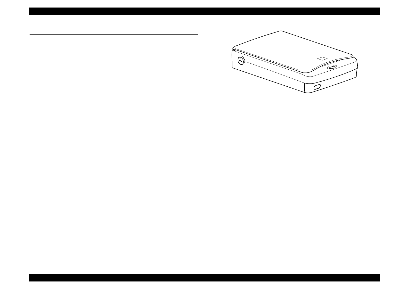
Figure 1-1. Exterior View of Perfection 1640SU
EPSON Smart Panel
-Same functions as ’Stylus Scan 2000/2500’.
-Achieve easy scanning with a start button.
-Export a image data to applications easily.
Instant Photo Print Utility
Modify from ’Perfection 1200’
New Twain functions
-ITR(Image Type Recognition)
-Auto skew correction
Hybrid Interface
Include both USB and SCSI interfaces in one
Option
ADF(Based on ’Perfection 636 ADF’, and change external design
according to ’Perfection 1640SU’)
Film Adapter (Same sa ’Perfection 1200 Film Adapter’)
Product Description Features 9
Page 10

EPSON Perfection 1640SU Revision A
1.2 Product Description
GENERAL SPECIFICATION
Product Type: Flatbed color image scanner
Sub-scanning method: Movement of the Scanner-Head
Photoelectric device: 6 line alternate color CCD
Maximum Read Area: 8.5 x 11.7 (216 x 297mm)
Maximum effective picture element:
13600 x 18720 pixels (1600 dpi)
Scanning Resolution:
Main 1600 dpi (Optical resolution by 6 line CCD with 40800 pixels)
Sub 3200 dpi with Micro Step
Output resolution: 50 ∼ 6400 dpi (1 dpi step)
(12800dpi scanning is achieved by
6400dpi x 200%)
Gray scale levels: 14 bits/pixel (Input 14 bits/pixel, Output 1-8/bits/
pixel)
Color Separation: By the color filter of CCD
Zoom: 50 ∼ 200% (1% step)
Scanning Speed:
Color: 8.7 msec/line
Monochrome (bi-level): 3.0 msec/line
Command level: ESC/I (B8), FS
Gamma Correction: CRT 2 level (A, B)
PRINTER 3 level (A, B, C)
User defined 1 level
Color Correction: Impact-Dot Printer
Thermal Printer
Ink-Jet Printer
CRT Display
User defined
Brightness: 7 levels
Line Art: Fixed threshold
TET (Text Enhancement Technology)
Digital halftoning: AAS
Error Diffusion 3 modes (A, B, C)
(Bi-level, Quad-level)Dither (Resident) 4 modes (A, B, C, D)
Dither (User defined) 2 modes (A, B)
Interface (Resident):SCSI (50-pin Half pitch Connectors) x 1pcs
USB (Type-B Receptacle Connector) x 1pc
USB Hosts: All of USB ports work correctly. (The functionality of
the USB port (s) must be ensured by the vendor of the
Host)
Number of Hub: This device must be in the Tier 1 or 2 with
recommended USB cable. (Tier1:Host-this device
Tier2: Host-Hub-this device)
Light Source: White Cold cathode Fluorescent Lamp
Option : ADF, Film Adapter
Start button: Ease of use with EPSON Smart Panel
Operating System:
SCSI I/F: Microsoft Windows 95/98, Windows NT4.0/Windows2000
Microsoft Windows Millennium Edition
Macintosh System 8.0 or later
USB I/F: Microsoft Windows 98 (Pre-install model)
Microsoft Windo w s2 000 (Pre-install mo de l or up gr ad e
model from Windows 98 pre-install model)
Microsoft Windows Millennium Edition (Pre-install model
or upgrade mo del from Window s 98 pre-install mode l)
Apple System 8.1 or later (USB equipped model)
Product Description Product Description 10
Page 11

EPSON Perfection 1640SU Revision A
ELECTRICAL SPECIFICATIONS
Rated voltage: AC100-120V
AC220-240V
Input voltage: AC 100 -120V ±10%
AC 220 - 240V ±
Rated Current : 0.5A (Input AC100V)
0.3A (Input AC200V)
Rated Frequency Range:50-60 Hz
Input Frequency Range:49.5-60.5 Hz
Power consumption: Approx. 25W (Operating)
Approx. 10W (Stand-by)
Insulation resistance: 10 MΩ at 500VDC (between AC line and chassis)
Dielectric strength: AC.1.2kV, 1 min (between AC line and chassis)
10%
SAFETY, EMC, EPA
Safety: UL 1950 (UL)
CSA C22.2 NO.950 (CSA)
EN60950 (VDE)
IEC950 (ROSTEST, PSB)
EMC: FCC Part15 Subpart B Class B
CSA C108.8 Class B
AS/NZS3548 Class B
CISPR Pub22 Class B
CNS 1348 Class B
RESISTANCE TO ELECTRIC NOISE
Static electricity: panel - 10 kV
metal - 7kV/150 pF, 150Ω
ENVIRONMENTAL CONDITIONS
Temperature:
Operating: 5 °C to 35 °C
Storage: -25 °C to 60 °C
Humidity:
Operating: 10 to 80%, no condensation
Storage: 10 to 85%, no condensation
RELIABILITY
MCBF: 30, 000 cycle
OPERATING CONDITIONS
Dust: Ordinary office or home conditions. Extreme dust
should be avoided.
Illumination: Operation under direct sunlight or near strong light
source is not guaranteed and should be avoided.
DOCUMENT
CE Marking:
Low Voltage Directive 73/23/EEC EN60950
EMC Directive 89/336/EEC EN55022 Class B
EN6100-3-2
EN6100-3-3
EN50082-1
IEC60801-2/801-3/801-4
EPA: Energy Star Program
Reflective type: Documents which has a smooth surface such as a
printing and photograph.
Transparency type (with transparency unit)
Reversal film
Negative film
Product Description Product Description 11
Page 12
EPSON Perfection 1640SU Revision A
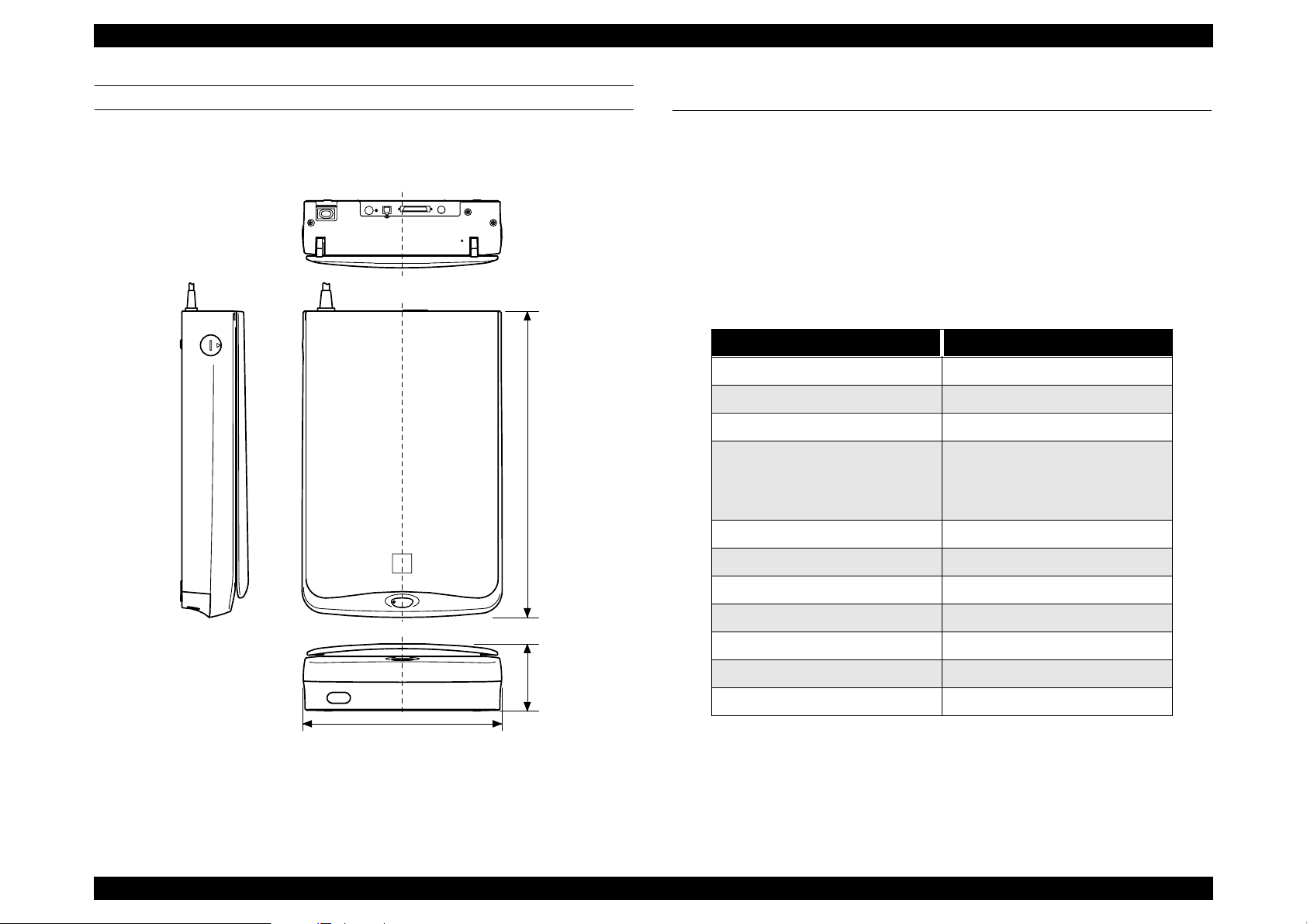
PHYSICAL DIMENSIONS AND WEIGHT
Dimensions: 289(W) x 442(D) x 96(H) mm
Weight: Approx. 4.5 Kg
442mm
1.3 Interface Specification
1.3.1 SCSI Interface
Basic specifications
Any items not included in this specification shall be in compliance with
ANSI X 3T9.2/375R Revision 10L (SCSI 2)
Function
The following functions are available, which are included in ANSI X3T9.2/
375R Revision 10L (SCSI 2)
Table 1-1. SCSI Interface Function
Function Note
Bus Free Phase
Arbitration phase
Selection /Re-selection phase
The LUN (Logical Unit Number) is
Command phase
Data in phase
fixed at “0” in this device. The
Command Link Function is not
supported.
Data out phase
Status phase
Message in phase
96mm
289mm
Figure 1-2. Size
Message out phase
Attention condition
Reset condition
SCAM (SCSI Configured Auto Magically specification) [X3T9.2/93109r5]
Electric specification
Compliant to ANSI X3T9.2/375R Revision 10L (SCSI 2)
Single ended
Product Description Interface Specification 12
Page 13
EPSON Perfection 1640SU Revision A
Connector: Two 50-pin connectors
Terminator: Internal terminator
(always ON ----terminator available)
SCSI ID: The SCSI ID is set with a rotary switch on the rear panel.
The switch numbers are corresponded to the available
address and can be set from 0 to 7.
Others are reserved
Factory setting ID=2
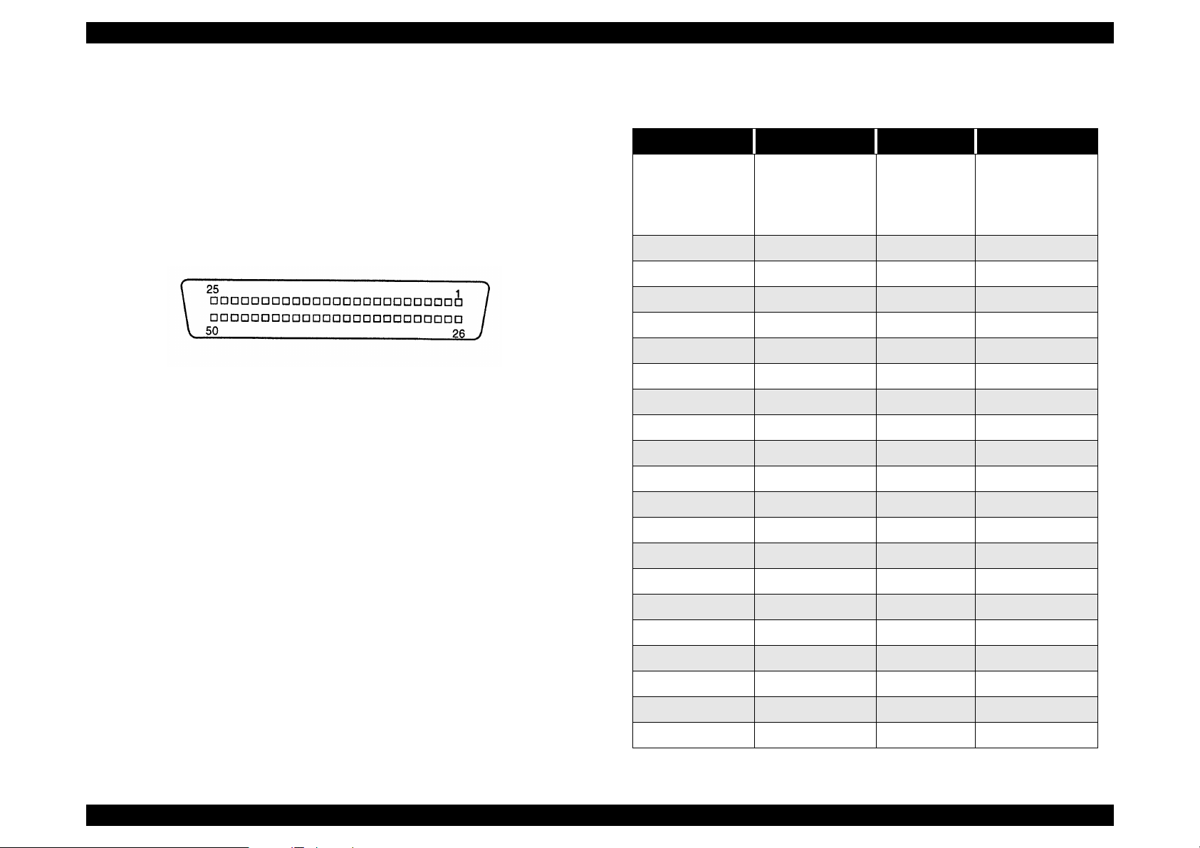
Table 1-2. SCSI Connector Pin Assignment
Signal I/O Pin No. Specification
1 ∼12
GND
NC 13
DB0 I/O 26 Data Bus 0
DB1 I/O 27 Data Bus 1
DB2 I/O 28 Data Bus 2
14 ∼ 25
35 ∼ 37
39, 40, 42
50pin connector
Figure 1-3. SCSI Connector Pin Assignment
DB3 I/O 29 Data Bus 3
DB4 I/O 30 Data Bus 4
DB5 I/O 31 Data Bus 5
DB6 I/O 32 Data Bus 6
DB7 I/O 33 Data Bus 7
DBP I/O 34 Data Bus Parity
TERMPWR 38 Terminator Power
ATN I 41 Attention
BSY I/O 43 Busy
ACK I 44 Acknowledge
RST I 45 Reset
MSG O 46 Message
SEL I/O 47 Select
C/D O 48 Command/Data
REQ O 49 Request
I/O O 50 Input/Output
Product Description Interface Specification 13
Page 14
EPSON Perfection 1640SU Revision A
1.3.2 USB Interface
Component: This device supports the following configurations.
Table 1-3. Configurations
Class: Vender-specific
Max. packet size of endpoint 0: 64 byte
Device
Component
Interface 0
End point 1
End point 2
Vender ID: 0x04B8
Product ID: 0x010A
No.of component: 1
Supported Interface: 1
Characteristic
• Self power
• Remote wake up function support
Power consumption:2mA
substitutes setting value: NO
Endpoint: 2
Class: Vender-specific
Bulk IN transfer
Max. packet size: 64 byte
Bulk out transfer
Max. packet size: 64 byte
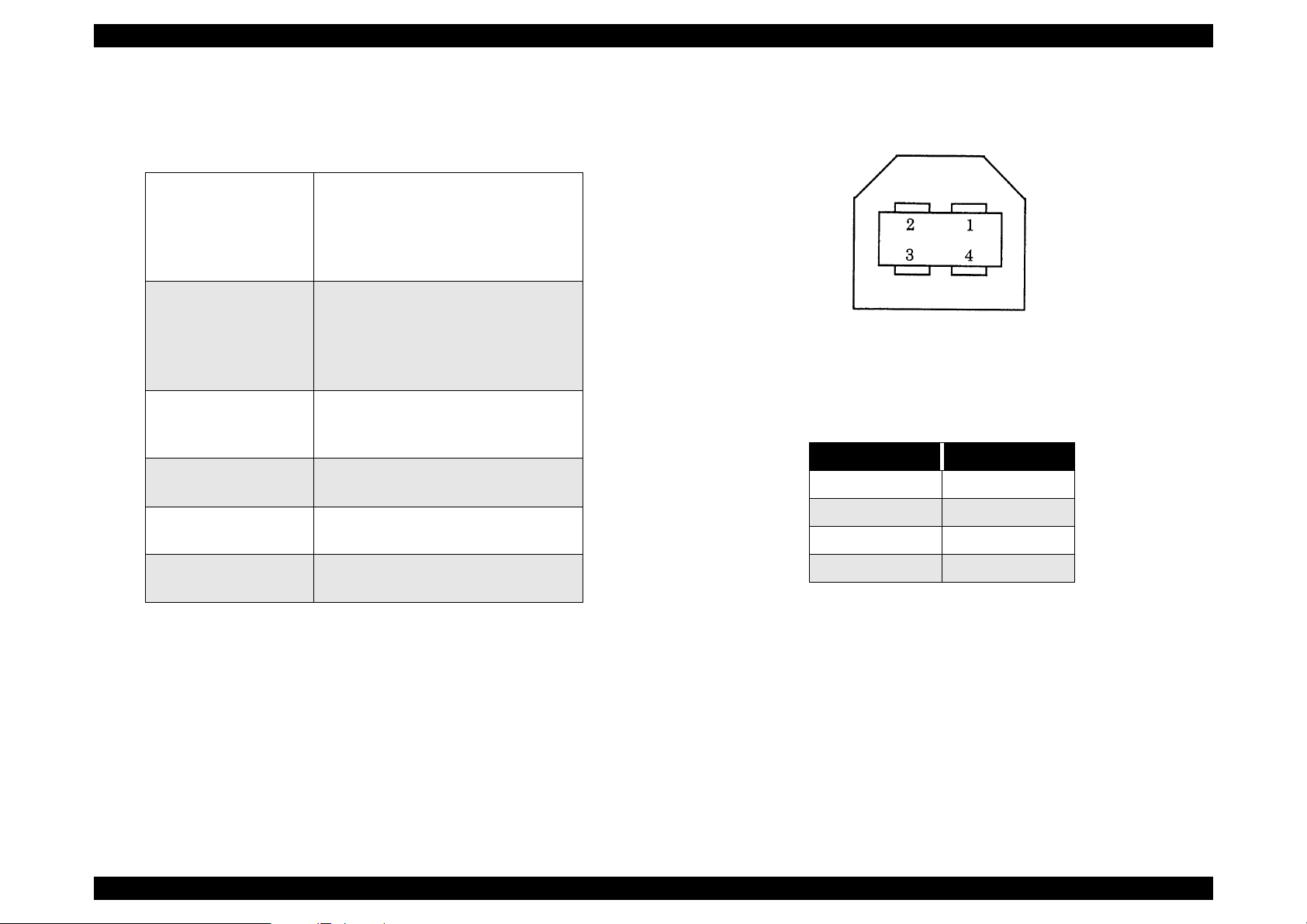
Figure 1-4. Receptacle (Series B)
Table 1-4. Connector Pin Assignment
Pin No. Signal
1VCC
2 - Data
3+ Data
String descriptor
Electric specification: Compliant to the high speed (12M bps) mode of
Producer: “EPSON”
Product Name: Perfection 1640
4 GND
Universal Serial Bus Specification Rev.1.1.
Connector: Receptacle (Series B) (Figure 1-4 and Table1-4)
Product Description Interface Specification 14
Page 15
EPSON Perfection 1640SU Revision A
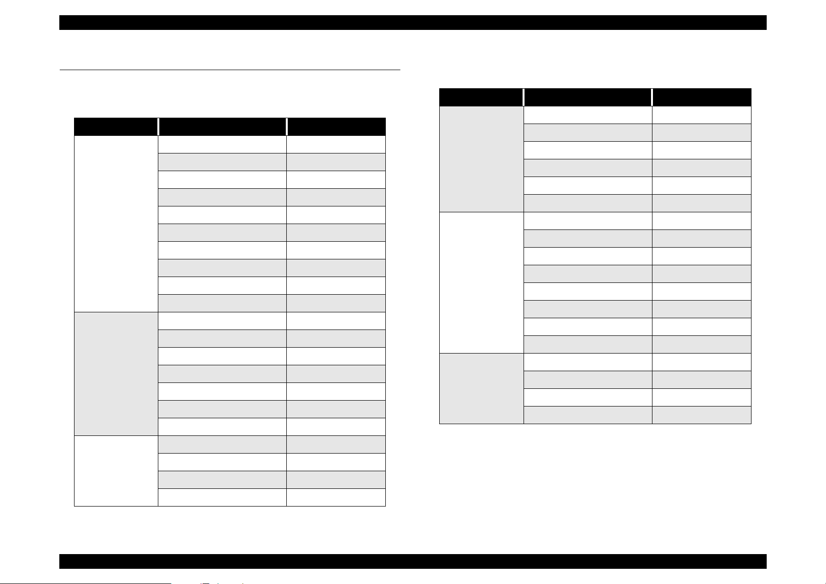
1.4 Control Code
The command level is ESC/I-B7 and supported commands are shown below.
Table 1-5. Control Codes
Category Command Name Code
ID request ESC I
Status request ESC F
Extension status request ESC f
Status setting request ESC S
Execute Command
Data format
setting
Read start command ESC G
Push Button Status request ESC !
Expansion ID request FS I
Scanner Status request FS F
Read parameter request FS S
New read start FS G
Sets Data format ESC D i
Sets resolution rate ESC R n1 n2
Sets zoom rate ESC H i1 i2
Sets the reading range ESC A n1 n2 n3 n4
Sets the color ESC C i
Mirroring ESC K i
Sets reading parameter FS W
Table 1-6. Control Codes
Category Command Name Code
Set Digital Halftoning ESC B i
Set Auto Area Segmentation ESC s i
Download Dither Pattern ESC b ijd (j2)
Image process
Color correction ESC M i
Download Color Correction ESC m df d2...d9
Set Threshold ESC t i
Set scanning mode ESC g i
Initialize ESC @
Set line counter ESC d i
Control option ESC e i
Auxiliary
Focus adjustment ESC p i
Focus position status request ESC q
Eject paper FF
Film type ESC N i
Normal response ACK
Abnormal response NACK
Control
Abort scanning CAN
Header STX
Set brightness ESC L i
Correction process
Set Gamma correction ESC Z i
Set Gamma correction table ESC z i d0 d1...d255
Set sharpness ESC Q i
Product Description Control Code 15
Page 16
EPSON Perfection 1640SU Revision A
1.5 Exterior Function
1.5.1 Switch Specification
OPERATE Switch
Turns the scanner ON/OFF
Pressing this switch at power ON initializes the scanner
PUSH Button
The status of this button can be checked by [ESC !].
SCSI ID switch (rotary type)
0 - 7: SCSI ID (Factory setting ID=2)
Other: Reserved
1.5.2 Indicators
Indicator display
OPERATE (Green LED)
OPERATE switch is ON and power is ON.
READY (Green LED)
*This lamp becomes ON when the command or receiving/sending the
data is available. (During scanning, READY lamp repeats blinking,
according to the data transfer)
*READY lamp blinks with with ERROR LED when an error occurs.
ERROR (Red LED)
This lamp blinks when an error (s) is detected.
READY LED
(green)
ON ON Command error
OFF Blink
OFF Blink Fatal error
Blink Blink Option error
Table 1-7. Error Indication
ERROR LED (red) Error ty pe
Communication
error
Product Description Exterior Function 16
Page 17

EPSON Perfection 1640SU Revision A
Remedy: Turn the scanner off and then back on. Send ESC@
1.6 Process when an error happens
Command error
Cause: Unidentified command or unidentified command
parameter is detected.
Disposition: The scanner ignores the wrong command or parameter.
(Therefore, the current setting or the default value remain
effective.)
Scanner sends NACK, and waits for the next command or
parameter.
Indicator: Red LED ON
Remedy: The error condition is cleared when the scanner receives
a correct command.
Interface error (Communication error)
Cause: Wrong procedure is detected in the interface
communication. In the case of SCSI, a transmission is
frozen more than 30 seconds except BUS FREE phase.
Disposition:The lamp goes off and the scanner stops operation.
code to the scanner. RESET signal in SCSI turns active.
Complete BUS DEVICE RESET message in SCSI.
Acceptable command: ESC F, ESC f, ESC @
Option error:
This error occurs by the following causes, when an optional unit is installed
and its operation is available by the optional control command (ESC e).
Cause: Unit cover open
Paper Empty
Disposition:The bit 7 of the status byte is set to “1”
Indicator: READY LED Blink
ERROR LED Blink
Remedy: Remove the error condition
Acceptable command: ESC F, ESC f, ESC @
Indicator: READY LED Off
ERROR LED (red) blinking (short interval)
Remedy: Turn the scanner off and then back on. RST signal in SCSI
turns active.
Acceptable command : Nothing
Fatal error
Cause: The lamp is broken. Power is turned on before removing
the transportation screw.
Disposition: The lamp goes off and the scanner stops operation.
The bit 7 of the status byte is set.
Indicator: READY LED Off
ERROR LED Blinks
Product Description Process when an error happens 17
Page 18

OPERATING PRINCIPLES
CHAPTER
2
Page 19
EPSON Perfection 1640SU Revision A
CCD Sensor Board: This board has Color CCD line sensor
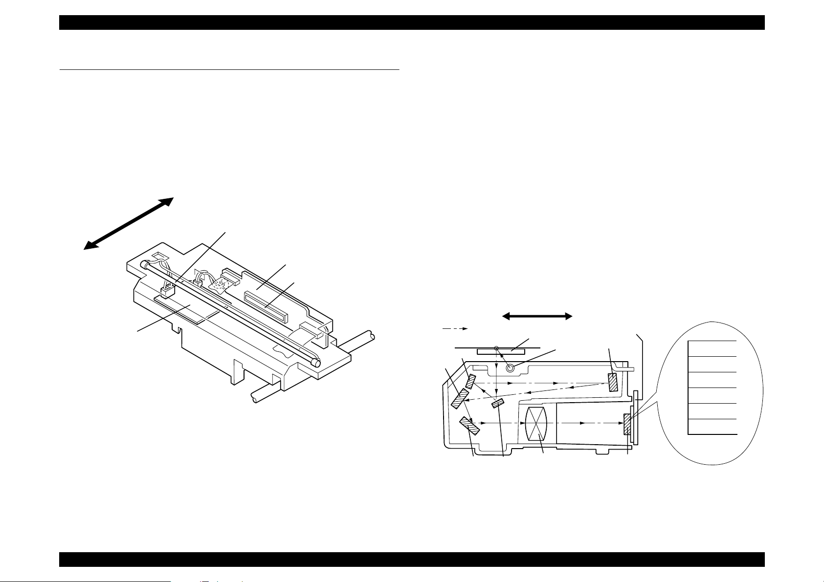
2.1 Engine Mechanism
This section explains the engine function and operating principles. Engine can
be divided into Carriage Unit and Carriage Move Mechanism.
2.1.1 Carriage Unit
Carriage unit is mainly composed of CCD sensor board, Inverter board, Lamp
(light source), Mirror and Lens mechanism.
Rear
Lamp
CCD Sensor
Front
Board
CCD Sensor
(independent R,G,B), and controls it and drives
circuit.
Inverter Board: This board generates voltage to drive the lamp
by pressuring up to the +24VDC and converting it
from direct current to alternating current.
Lamp: White cold fluorescent Lamp is used as light
source. When the light quantity is not stable,
the scanner blinks the Operate light until the
light becomes stable and goes to stand-by mode.
Mirror and Lens Mechanism:The light emitted to the document
reaches the CCD sensor after being
reflected on some mirrors one after
another. Not by changing the light
source to create R/G/B light component
which can be found in the previous
models, Color CCD itself creates each
R/G/B light component.
CCD Sensor
Mirror3
Board
B(main)
B(sub)
G(main)
G(sub)
R(main)
R(sub)
Inverter Board
Mirror2
Mirror4
Front
Scanned image
Document
Rear
Lamp
Figure 2-1. Carriage Unit Component
Mirror5
Mirror1
Lens
CCD Sensor
Figure 2-2. Mirror, Lens Mechanism
Operating Principles Engine Mechanism 19
Page 20
EPSON Perfection 1640SU Revision A
n
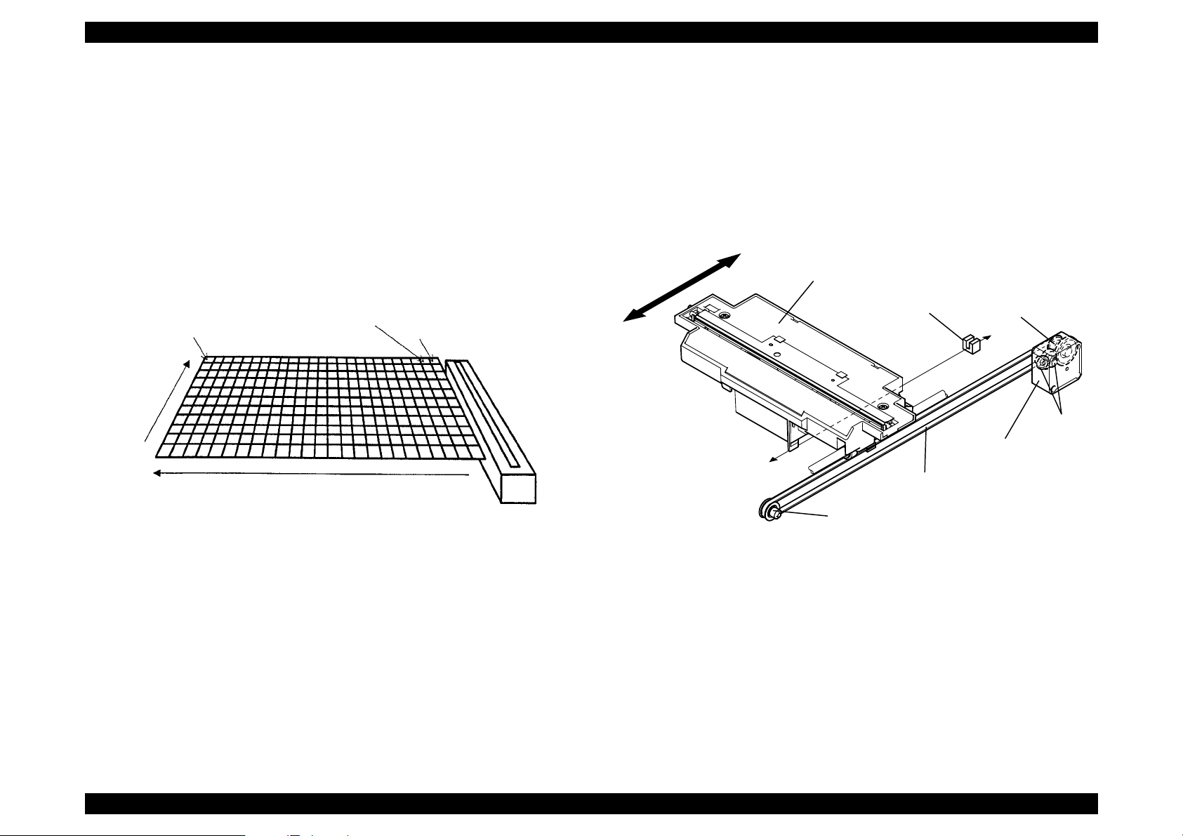
2.1.2 Carriage Move Mechanism
Scanning image is performed in the main scan direction (=1 line) by the CCD
sensor and in the sub-scan direction (=several lines) combined with carriage
unit movement. (See the figure below)
Line type, color CCD sensor can scan 1 line in main scan direction (parallel to
the carriage unit) by one time. When scanning next lines after the second line
in sub-scan direction, CR driving moves the carriage unit, which has CCD
sensor inside, and scan the other lines. The scanned data is sent to the control
board. The scanned data for “n” lines and “n-1” line are processed
consecutively.
Second
1 pixel
Document
Main Scan
Direction
Sub-scan Direction by
CR Movement
Line
First Line
Scanner Head
(Carriage)
Carriage Unit slides into sub-scan direction along with the guide rail. For this
sliding operation, the carriage motor drives the timing belt attached to the
carriage unit by conveying the driving force through the drive pulley and
reduction gear. Scanning start position is determined by CR HP sensor, which
is located on the control board. Since the stepping motor is used for CR motor,
carriage home position is controlled under the open loop system. (See the
figure below)
Rear
Carriage Unit
CR HP
Sensor
Front
Timing Belt
Drive Pulley
Drive Pulley
CR Motor
Reductio
Gear
Figure 2-3. Carriage Movement
Figure 2-4. Carriage Operation
Operating Principles Engine Mechanism 20
Page 21
EPSON Perfection 1640SU Revision A
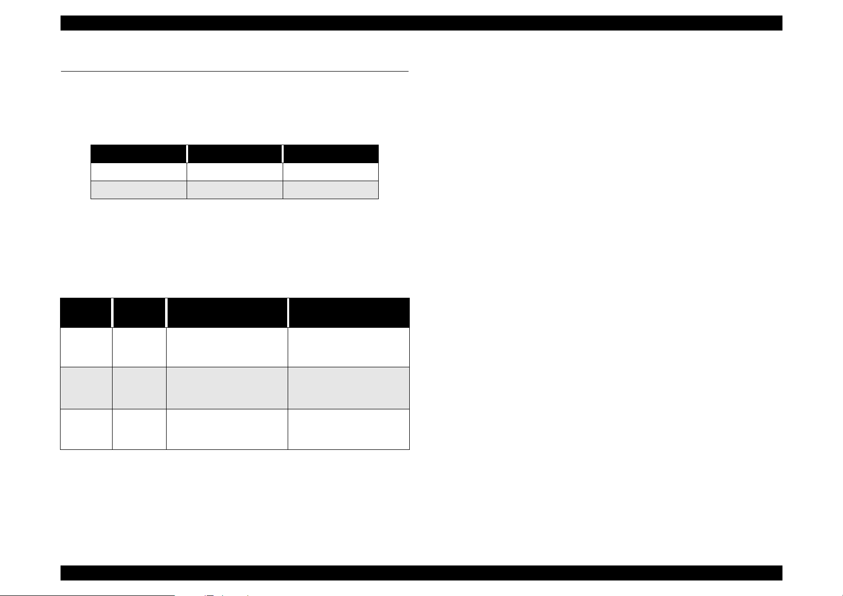
2.2 Power Supply Circuit
Power supply circuit in this scanner generates direct current DC power
necessary for driving the controller board and scanner engine. Table below
shows each power supply circuit for different destinations.
Table 2-1. Power Supply Circuit Board for Destination
Specification Unit Part No. Fuse
100-120 VAC Range 2031592 2.5 A/125 VAC
220-240 VAC Range 2031593 T2.5AH/250 VAC
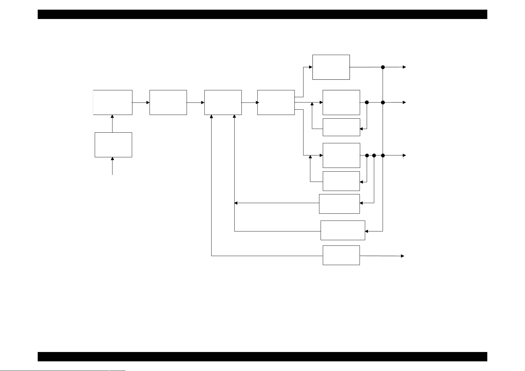
Figure 2-5 shows diagram of power supply circuit.
Output from the power supply circuit is performed by closing or opening the No.
4 pin of CN102 connector. When opening, as it is shown in the Table below,
each output voltage becomes active. Also, each output voltage has over
current protection and over voltage protection circuit.
Table 2-2. Output and Protection Function
Output
Voltage
5 VDC 1.2A
12 VDC 0.2A
24 VDC 0.7A
Output
Current
Over Current Protection
(Current value to activate)
Fold-back characteri st ic.
Automatic Recove ry. (Less
than 1A)
Constant current limiting.
Automatic Recovery.
(less than 0.5 A)
Shut down. Turn off the
power and back on to
recover.
Over voltage Protection
(Voltage value to activate)
Shut down. Turn off the
power and back on to
recover. (5.5 -7.5 VDC)
Shut down. Turn off the
power and back on to
recover. (14 -17 VDC)
Shut down. Turn off the
power and back on to
recover. (28 -33 VDC)
NOTE: 1. If a part of output is shut down, all the other output are also shut
down.
2. Off time required to recover is maximum 5 minutes.
Operating Principles Power Supply Circuit 21
Page 22
EPSON Perfection 1640SU Revision A
F u l l W a v e
R e c t i f i e r C i r c u i t
F i l t e r C i r c u i t
A C V o l t g e I n p u t
S m o o t h i n g
C i r c u i t
S w i t c h i n g
C i r c u i t
S m o o t h i n g
C i r c u i t
+ 1 2 V D C
R e g u l a t o r I C
+ 5 V D C
R e g u l a t o r
C i r c u i t
O v e r C u r r e n t
P r o t e c t i o n
C i r c u i t
S m o o t h i n g
C i r c u i t
+ 2 4 V D C
C o n t r o l C i r c u i t
+ 2 4 V D C O v e r
C u r r e n t P r o t e c t i o n C i r c u i t
+ 5 / + 1 2 / + 2 4 V D C
O v e r V o l t a g e
P r o t e c t i o n C i r c u i t
+ 1 2 V D C
+ 5 V D C
+ 2 4 V D C
P o w e r S u p p l y
S W C i r c u i t
P o w e r S W
( P W - S W )
Figure 2-5. Power Supply Circuit Block Diagram
Operating Principles Power Supply Circuit 22
Page 23
EPSON Perfection 1640SU Revision A
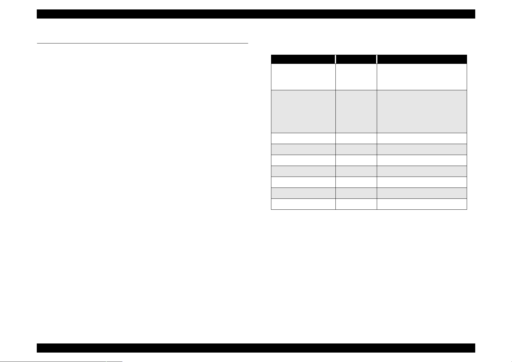
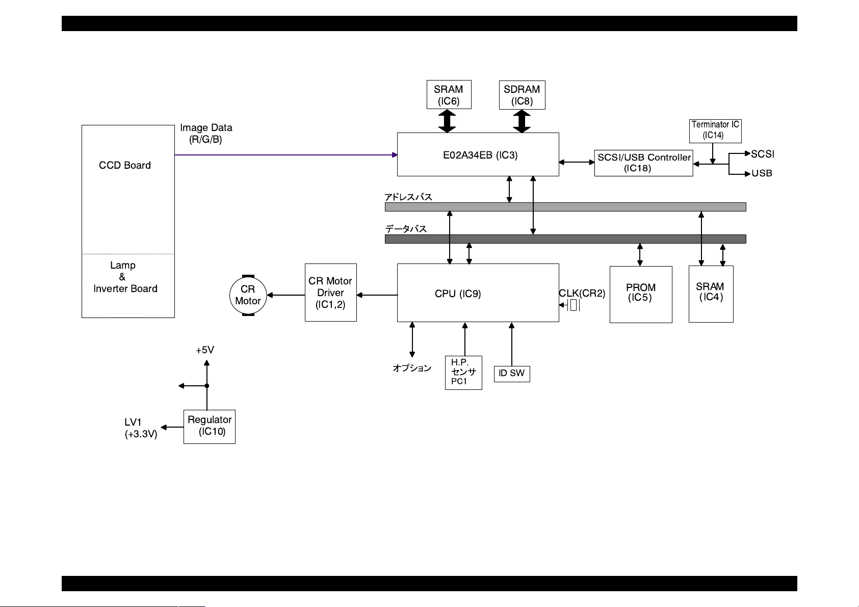
2.3 Control Circuit
Table 2-3. Major ICs
2.3.1 Control Circuit Overview
This scanner uses the one-tip 16-bit bus CPU (IC9) at 20MHz frequency.
Image data processing, correction, CCD sensor board, A/D converter control
are operated at ASIC (IC3). Table 2-3 shows major IC functions.
H8S/2350 IC9
E02A34EB IC3
MB81F641642D IC8 SDRAM 64Mbit
IS61C256AH IC4, IC6
A3957SLB IC1, 2 CR motor driver IC
MBM28F200B IC5 PROM
BH9596FP-Y IC14 Terminator IC
IC Location Function
CPU
24-bit Address Bus
16-bit Data Bus
ASIC
• CCD Control
• Line (sharpness) Control
• Image Processing
• Memory Control
SRAM 32k x 8 bit
SPC7215F0A IC18 SCSI/USB Controller
SSA20.00BR CR2 2 0 MHz clock for CPU
Operating Principles Control Circuit 23
Page 24
EPSON Perfection 1640SU Revision A
CCD Board
Lamp
&
Inverter Board
Image Data
(R/G/B)
+5V
CR
Motor
CR Motor
Driver
(IC1,2)
SRAM
(IC6)
E02A34EB (IC3)
CPU (IC9)
H.P.
SDRAM
(IC8)
ID SW
SCSI/USB Controller
CLK(CR2)
(IC18)
PROM
(IC5 )
Terminator IC
(IC14)
SRAM
(IC
4
)
SCSI
USB
LV1
(+3.3V)
Regulator
(IC10)
Figure 2-6. Control Circuit Block Diagram
Operating Principles Control Circuit 24
Page 25

TROUBLESHOOTING
CHAPTER
3
Page 26
EPSON Perfection 1640SU Revision A
3.1 Overview
This chapter explains the troubleshooting of this scanner.
3.2 Self-Diagnostic Function
The self-diagnostic function of this scanner lets the scanner to check the
condition of each component automatically. If it detects a faulty component, it
indicates the status using the Operate light. See Table3-1.
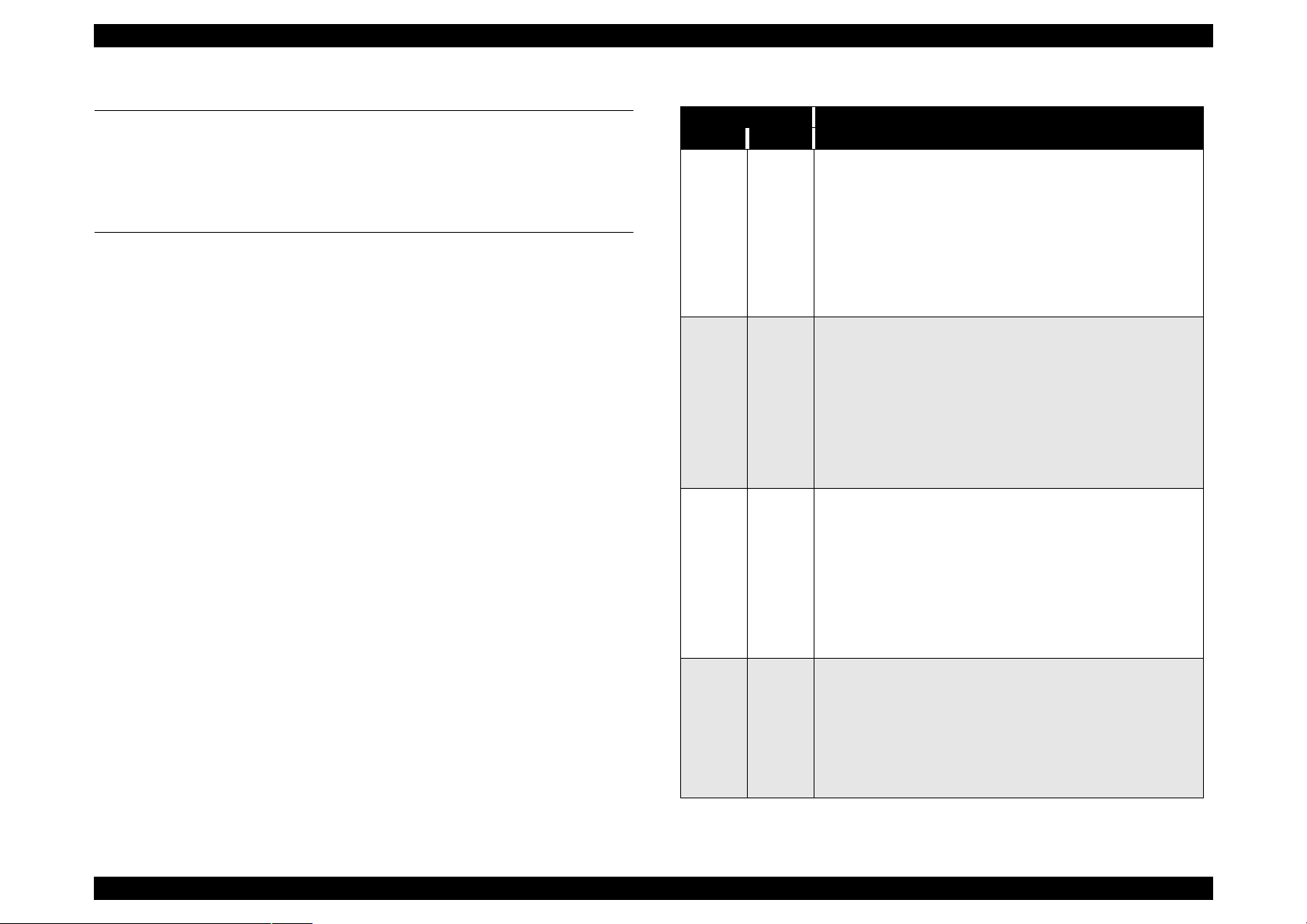
Table 3-1. Self-Diagnostic Indication
LED Light Error Type (Cause, Remedy)
Green Red
Command Error
• Cause: Unidentified command or unidentified command
parameter is detected.
• Disposition: The scanner ignores the wrong command or
OFF ON
OFF Blink
OFF Blink
Blink Blink
parameter. (Therefore, the current settings or the default
value remain effective) Scanner sends NACK, and waits
next command or parameter.
• Remedy: The error condition is cleared when the scanner
received a correct command.
Interface Error
• Wrong pr ocedure is detected in the interfa c e
communication. In the case of SCSI, a transmission is
frozen more than 30 seconds except BUS FREE phase.
• Disposition: The lamp goes off and the scanner stops
operation.
• Turn off the scanner and then b ack on. RST si gnal in SCS I
turns active.
• Acceptable command: Nothing
Fatal Error
• Cause: The lamp is broken. Power is turned on before
removing the transportation screw. System break down.
• Disposition: The lamp goes off and the scanner stops
operation. The bit 7 of the status is set.
• Remedy: Turn the scanner off and then back on. Send
ESC@ codes to the scanner. RESET signal in SCSI turns
active. Complete BUS DEVICE RESET message in SCSI.
• Acceptable command: [ESC F, ESC f, ESC @]
Option Error
(Only when the optional unit is installed and operation is
available by [ESC e].)
• Cause: Unit cover open, or paper Empty
• Disposition: The bit 7 of the status byte is set to “1”.
• Remedy:Remove the error condition.
• Acceptable command:[ESC F, ESC f, ESC @]
Troubleshooting Overview 26
Page 27

EPSON Perfection 1640SU Revision A
3.3 Troubleshooting
This section describes troubleshooting from the abnormal phenomenon. You
can isolate the faulty unit based on the abnormal phenomenon. See the table
below to find the closest phenomenon and the corresponding table to refer to.
Table 3-2. Abnormal Phenomenon and corresponding Tables
Phenomenon Description Ref, Table
Scanner does not
operate even its power i s
On.
Fatal Error occurs and is
not cleared after turning
off and back on the
scanner.
Scanned image is
unclear.
“Interface Error” is
indicated.
“Option Error” occurs.
Optional unit (ADF/TPU)
does not operate.
• Operate Light on the control panel
does not come On.
• Scanner does not operate the
initialization.
• Carriage Unit does not operate.
• Carriage Unit crashes into the front or
rear frame and then the error is
indicated.
• The lamp does not light up.
Scanned image is unclear. 3-8
• SCSI Interface Error
• USB Interface Error
• Optional unit does not operate
correctly.
3-3
3-4
3-5
3-6
3-7
3-9
3-10
3-11
Table 3-3. Panel LED does not turn On.
Cause Step Checkpoint Finding Solution
Connector CN1 on
the power board is
disconnected.
Connector CN101 or
CN102 on the power
board disconnected.
Fuse on the power
board has blown out.
The power board.is
broken.
Connector CN7 on
the power board is
disconnected.
The control board is
broken.
1 Is the connector
CN1 on the power
board
disconnected?
2 Is the connector
CN101 or CN102
on the power board
disconnected?
3 Has the fuse on the
power board blown
out?
4 With the scanner
On, check the
voltage output leve l
between pins 8/
9(+) and pins 6/7(-)
on the power
board. Is the
voltage +5VDC?
5 Is the connector
CN7 on the control
board
disconnected?
6 --- --- Replace the control
Yes Connect CN1
Yes Connect CN101 or
Yes Replace the fuse.
No Replace the power
Yes Connect CN7
properly.
102 properly.
board.
properly.
board.
Table 3-4. Scan n e r is no t in itialized
Cause Step Checkpoint Finding Solution
Connector CN1 on
the power board is
disconnected.
1 Is the connector
CN1 on the power
board
disconnected?
Yes Connect CN1
properly.
Troubleshooting Troubleshooting 27
Page 28

EPSON Perfection 1640SU Revision A
Table 3-5. Carriage Unit does not operate Table 3-6. Carriage moves but an error is indicated
Cause Step Checkpoint Finding Solution
Power
board is
broken.
Carriage
Unit (or CR
move
mechanism)
is broken.
CR Motor is
broken
Main board
is broken.
1 With the scanner power on,
check the voltage output level
between the Pins 4/5(+) and
Pins 6/7 (- ) for CN101 on the
power board. Is it +24VDC?
2
Is grease (G-26) applied
correctly?
3 • With power ON and the
scanner upper case
removed, does CR motor
move?
• With the CR motor
removed, does the
carriage unit move
smoothly?
4 Disconnect the connector
CN6 on the main board, then
use the tester and check the
coil resistance between Pin2
and 4 and between Pin1 and
3. Is the resistanc e of 2 points
about 6.2
5 If any motor coil is shorted,
check the CR motor drive
circuit in the order below.
1.)Set the tester on Ohms.
2.)Place the (-) lead of the
tester on any of Pins 1,2, 3 or
4 of CN6 on the main board.
3.)Place the (+) lead of the
tester on Pin 6/7 of CN7 on
the main board.
With the scanner off, doe s the
meter show “
6 --- --- Replace the main
Ω?
”?
∞
No Replace the power
board.
No Apply the grease to
the appointed
position. (See Ch6)
No Check the carriage
move mechanism
and replace the
corresponding parts
or disassemble and
assemble the part.
No Replace the CR
motor.
No Replace the main
board.
board.
Cause Step Checkpoint Finding Solution
CR home position
sensor is broken.
1 Check the signal
level.
•Check the
signal/status
level between
C(+) and E(-) of
PC1.
H (about 4.5V)/
when C-E of PC1 is
closed.
L (0.3V)/when C-E
of PC1 is opened.
-- Replace the CR
Table 3-7. Lamp does not light up
Cause Step Checkpoint Finding Solution
Connector CN4 on
the control board is
disconnected.
Connector CN1 or
CN2 on the CCD
board disconnected.
Lamp is not
connected properly
to the connector on
the inverter board.
Lamp is broken. 4 Does the lamp light
Inverter board is
broken.
Main board is
broken.
1 Is the connector CN4
on the control board
disconnected?
2 Is the connector CN1
or CN2 on the CCD
board disconnected?
3 Is the lamp connected
properly to the
connector on the
inverter board?
after it is replaced?
5 Does it operate
properly after
replacing it?
6 --- --- Replace the main
Yes Connect CN4
Yes Connect CN1 or 2
No Connect the lamp
Yes Replace the
Yes Replace the
home position
sensor (PC1) on
the main board.
properly.
properly.
properly.
lamp.
inverter board.
board.
Troubleshooting Troubleshooting 28
Page 29

EPSON Perfection 1640SU Revision A
Table 3-8. Scanned image is unclear
Cause Step Checkpoint Finding Solution
Mirror in the carriage
unit is dirty.
CCD sensor board is
broken.
Main board is
broken.
1 Is the image
scanned clearly
after cleaning the
mirror?
2 --- -- Replace the CCD
3 --- --- Replace the main
No Clean the lamp
Table 3-9. SCSI Interface Error
Cause Step Checkpoint Finding Solution
Terminator switch is
set wrong.
SCSI setting is
wrong.
TWAIN driver, which
comes with the
scanner is not
installed correctly.
SCSI cable is
defective.
Main board is
broken.
1 Check the user’s
guide for the
correct setting. Is
the setting correct?
2 Check the user’s
guide for the
correct setting. Is
the setting correct?
3 Is the TWAIN driver
installed correctly?
4 Replace the SCSI
cable. Is the
operation normal?
5 --- --- Replace the main
No Set the terminator
No Set the SCSI
No Install the TWAIN
Yes Replace the SCSI
surface.
board.
board.
correctly.
correctly.
driver correctly (or
reinstall)
cable.
board.
Table 3-10. USB Interface Error
Cause Step Checkpoint Finding Solution
Host and O/S does
not support the USB.
TWAIN driver, which
comes with the
scanner is not
installed correctly
USB cable is broken. 3 Replace the USB
Main board is
broken.
1 On the Windows,
go to “My
”Prope
Computer”
rty”
Manager”, then,
check if “Universal
serial bus
controller” is
effective.
2 Is the TWAIN driver
installed correctly?
operation normal?
4 --- --- Replace the main
→
”Device
→
cable. Is the
No Replace the host.
No Install the TWAIN
Yes Replace the USB
Table 3-11. Option TPU/ADF does not operate
Cause Step Checkpoint Finding Solution
The cable of the
optional unit is
disconnected.
Main board is
broken.
Optional unit is
broken.
1 Is the connector
CN3 on the control
board
disconnected?
2 --- --- Replace the main
3 +24V line:Lamp,
Motor
+5V line: Sensor,
logic circuit.
Yes Connect the CN3
--- Replace the
driver correctly (or
reinstall)
cable.
board.
properly.
board.
defective part of the
optional unit.
Troubleshooting Troubleshooting 29
Page 30

DISASSEMBLY AND ASSEMBLY
CHAPTER
4
Page 31

EPSON Perfection 1640SU Revision A
4.1 Overview
This chapter describes for disassembling Perfection 1200 and precaution to
take during transportation.
4.1.1 Precaution
W A R N I N G
C A U T I O N
Before servicing, make sure that the power cable is
disconnected from the AC power socket and the interface
cable is removed.
Wear a pair at gloves to protect your hand from the sharp
edge in the scanner mechanism.
Use the stable and level table which has enough strength
for disassembling and assembling the scanner.
Get yourself enough room for servicing, considering the
size of the scanner.
Middle
Rear
4.1.2 Tools
Tools used for servicing are as listed in the table below.
Table 4-1. Tools
Description Availability SE Part No.
(+) Screw Driver O B743800200
(-) Screw Driver O B743000100
A pair of Tweezers O B641000100
Cutting Plier O B740400100
4.1.3 Screws
Screws used in this scanner are listed in the table below. Be sure to use the
correct types and numbers of screws for each part when assembling the
scanner.
Table 4-2. Abbreviation for Screws
Abbreviation Name
CP Cross-recessed Pan head screw
CBS Cross-recessed Binding head S-tite screw
CCP Cross-recessed Cup head P-tite
NOTE: Refer to Table 4-3 for screw shapes.
Left
Front
EPSON
Right
Figure 4-1. Notations
Disassembly and Assembly Overview 31
Page 32

EPSON Perfection 1640SU Revision A
Table 4-3. Screws
Head Shape Type Washer
Hole Appearance
Cross-recessed Binding
Pan
Cup
Standard
------
S-Tite
B-Tite
P-Tite
With Outside
toothed lock
washers
With Spring lock
washers
Disassembly and Assembly Overview 32
Page 33

EPSON Perfection 1640SU Revision A
4.2 Disassembly Procedures
4.2.1 Carriage Lock Release
1. Release the carriage lock located at left side of the scanner body by using
(-) screw driver.
Release
Lock
Figure 4-2. Carriage Lock Position
C A U T I O N
When you need to lock again for transportation, lock it while
letting the carriage be at home position.
Disassembly and Assembly Disassembly Procedures 33
Page 34

EPSON Perfection 1640SU Revision A
4.2.2 Document Cover Removal
1. Open the document cover vertically and pull it out upward.
Document
Cover
Hooks
Figure 4-3. Document Cover Removal
Disassembly and Assembly Disassembly Procedures 34
Page 35

EPSON Perfection 1640SU Revision A
4.2.3 Upper Cover Removal
1. Release the carriage lock. (see Section 4.2.1)
2. While holding the original cover with both hands so that it does not come
off, turn the main unit upside down.
3. Remove the two screws (CCS, M3x6) which are securing the front cover,
and then remove the front cover.
4. While holding the original cover with both hands so that it does not come
off, return the main unit to its original position.
5. Remove the document cover. (see Section 4.2.2)
6. Release two silver screws (CBS, M3x6) from the back of the scanner.
Front Cover
CCS (M3x6)
Figure 4-4. Front Cover Removal
CBS (M3x6)
Figure 4-5. Upper Cover Removal (1)
Disassembly and Assembly Disassembly Procedures 35
Page 36

EPSON Perfection 1640SU Revision A
7. Lift up the rear side of the upper cover and remove the upper cover toward
yourself, reeleasing three hooks securing the upper cover.
8. Disconnect the connector (CN2) from the sub board.
2 Hooks at
front side
Figure 4-6. Upper Cover Removal (2)
Connector
Sub Board
Figure 4-7. Upper Cover Removal (3)
Figure 4-8. After removing the upper cover
Disassembly and Assembly Disassembly Procedures 36
Page 37

EPSON Perfection 1640SU Revision A
4.2.4 Panel Board Removal
1. Release the carriage lock. (See Section 4.2.1)
2. Remove the upper cover. (See Section 4.2.3)
3. Remove the two screws (CBP, M3x8), then remove the panel board.
CBS (M3x6)
Figure 4-9. Panel Board Removal
Figure 4-10. Panel Board
Disassembly and Assembly Disassembly Procedures 37
Page 38

EPSON Perfection 1640SU Revision A
4.2.5 Inverter Lamp/Inverter Board Removal
1. Release the carriage lock. (see Section 4.2.1)
2. Remove the upper cover. (see Section 4.2.3)
3. Remove 2 black screws (CCP, M3x8) on the carriage unit.
4. Remove the carriage unit upper cover by lifting it up and pulling it front by
the (-) screw driver.
Figure 4-11. Disassembly of the Carriage Unit (1)
CCP (M3x8)
Figure 4-12. Disassembly of the Carriage Unit (2)
Disassembly and Assembly Disassembly Procedures 38
Page 39

EPSON Perfection 1640SU Revision A
)
5. Remove the inverter lamp connector from the inverter board.
6. Remove one black screw and a connector (2-pin) for CCD sensor board,
then remove the inverter board.
7. Remove the inverter lamp from the upper cover.
Inverter Board
C A U T I O N
When installing the inverter lamp, locate the wire as it is
shown in figures 4-13 and 4-14.
Connector (2-pin
Connector
Black screw
Figure 4-13. Disassembly of the Carriage Unit (3)
Upper Cover
Inverter Lamp
Inverter Board
Figure 4-14. Inverter Lamp Removal
Disassembly and Assembly Disassembly Procedures 39
Page 40

EPSON Perfection 1640SU Revision A
4.2.6 Main Board Removal
1. Release the carriage lock. (See Section 4.2.1)
2. Remove the upper cover. (See Section 4.2.3)
Carriage Unit
3. After removing 3 gold screws (CBS, M3x5) and 2 rear hooks, remove the
shield cover.
CBS
(M3x5)
Shield Cover
2 Hooks
Figure 4-15. Main Board Removal (1)
Disassembly and Assembly Disassembly Procedures 40
Page 41

EPSON Perfection 1640SU Revision A
4. Remove 2 screws (CP, M2.5x6) located around the I/F connector behind
the scanner body and 2 screws (CP, M3x5).
5. Remove each cable from CR motor connector (CN6), carriage FFC
connector (CN4, 5) and power supply unit connector (CN7).
6. Remove the four screws (CBS, M3x5) which are securing the main board
to the main unit.
7. Lift up the front part of the main board, pulling it toward you, and remove
the connector from the scanner body. Then, remove the main board.
CBS
(M3x5)
Carriage FFC
Connector
Power Supply Unit
Connector
CBS
(M3x5)
CP(M2.5x6)
CP (M3x5)
Figure 4-16. Main Board Removal (2)
CR Motor
Connector
CBS
(M3x5)
Figure 4-17. Main Board Removal (3)
Figure 4-18. Main Board
Disassembly and Assembly Disassembly Procedures 41
Page 42

EPSON Perfection 1640SU Revision A
4.2.7 Carriage Unit Removal
1. Release the carriage lock. (See Section 4.2.1)
2. Remove the upper cover. (See Section 4.2.3)
3. Remove the hexagon nut located back of the carriage guide shaft.
4. Remove the two screws (CBS, M3x5) which are securing the driven pulley
assembly.
Hexagon Nut
Figure 4-19. Hexagon Nut Removal
Carriage Unit
CBS(M3x5)
Figure 4-20. Driven Pulley Assembly Removal (1)
Disassembly and Assembly Disassembly Procedures 42
Page 43

EPSON Perfection 1640SU Revision A
5. Remove the driven pulley assembly from the frame toward the arrowed
direction.
6. Remove the carriage guide shaft from the driven pulley assembly, and then
remove the carriage guide shaft from the carriage unit.
Figure 4-21. Driven Pulley Assembly Removal (2)
Carriage Guide Shaft
Figure 4-22. Carriage Guide Shaft Removal
Disassembly and Assembly Disassembly Procedures 43
Page 44

EPSON Perfection 1640SU Revision A
7. Remove the timing belt from the carriage driven pulley and the CR motor
unit.
8. Remove the timing belt from the carriage.
Driven
Pulley
Timing Belt
Timing Belt
CR Motor Unit
Figure 4-23. Timing Belt Removal (1)
Timing Belt
Figure 4-24. Timing Belt Removal (2)
Disassembly and Assembly Disassembly Procedures 44
Page 45

EPSON Perfection 1640SU Revision A
9. Disconnect the two FFCs (white) from the rear of the carriage unit
(connectors and fixing tabs), and then remove the carriage unit.
FFC tab
Connector
FFC
Figure 4-25. Carriage Unit Removal
Figure 4-26. Carriage Unit
Disassembly and Assembly Disassembly Procedures 45
Page 46

EPSON Perfection 1640SU Revision A
4.2.8 Carriage Motor Removal
1. Release the carriage lock. (See section 4.2.1)
2. Remove the upper cover. (See section 4.2.3)
3. Remove the carriage unit. (See section 4.2.6)
4. Remove 3 gold screws (CBS, M3x5)and 2 rear hooks, and remove the
shield cover for the main board.
5. Remove 2 gold screws (CBS, M3x5) fixing the CR motor unit.
CBS(M3x5)
6. Remove CR motor unit cable from the connector of the main board, and
remove the CR motor unit.
Shield Cover
Hooks
Figure 4-27. Removing the Shield for the Main Board
CR Motor
Unit
Connector
CBS (M3x5)
Figure 4-28. CR Motor Unit Removal
Disassembly and Assembly Disassembly Procedures 46
Page 47

EPSON Perfection 1640SU Revision A
4.2.9 Sub Board Removal
1. Release the carriage lock. (See Section 4.2.1)
2. Remove the upper cover. (See Section 4.2.3)
3. Remove one gold screw (CBS, M3x6), and the shield cover for the panel
board.
C A U T I O N
4. Disconnect the connector of the sub board from the power unit, then
remove the sub board assembly.
In the next steps, move the carriage back and forth slowly
by hand, according to your necessity.
CBS (M3x6)
Figure 4-29. Sub Board Removal (1)
Sub Board
Assembly
Connector
Figure 4-30. Sub Board Removal (2)
Disassembly and Assembly Disassembly Procedures 47
Page 48

EPSON Perfection 1640SU Revision A
5. Remove one gold screw (CBS, M3x6), then remove the sub board.
CBS (M3x6)
Figure 4-31. Sub Board Removal (3)
Figure 4-32. Sub Board
Disassembly and Assembly Disassembly Procedures 48
Page 49

EPSON Perfection 1640SU Revision A
4.2.10 Power Supply Board Removal
1. Release the carriage lock. (See Section 4.2.1)
2. Remove the upper cover. (See Section 4.2.3)
Connector
C A U T I O N
3. Remove the cable of the sub board from the power supply board
connector (See figure 4-30)
4. Remove AC cable connector (lock type;Pick and release) from the power
supply board.
In the next steps, move the carriage back and forth slowly
by hand, according to your necessity.
Figure 4-33. Power Supply Board Removal (1)
AC Cable
Disassembly and Assembly Disassembly Procedures 49
Page 50

EPSON Perfection 1640SU Revision A
5. Remove 2 gold screws (CBS, 3x5) securing the shield board of the power
supply board, and remove the shield board toward inside of the body.
6. Disconnect the connector (lock type; push and release) and remove 5 gold
screws (CBS, 3x4) and power supply board from the shield board.
Shield Board
CBS(M3x5)
Figure 4-34. Power Supply Board Removal (2)
CBS (M3x4)
Connector
CBS (M3x4)
Figure 4-35. Power Supply Board Removal (3)
Figure 4-36. Power Supply Board
Disassembly and Assembly Disassembly Procedures 50
Page 51

ADJUSTMENT
CHAPTER
5
Page 52

EPSON Perfection 1640SU Revision A
This scanner needs no adjustment at the level of the service, including part
replacement, specified in Chapter 4 “Disassembly and Assembly”.
adjustment 52
Page 53

MAINTENANCE
CHAPTER
6
Page 54

EPSON Perfection 1640SU Revision A
6.1 Overview
This chapter provides information necessary to keep the scanner function in
optimum condition constantly and to prevent troubles.
6.1.1 Cleaning
Perform cleaning when stain is noticeable. Stain on the document glass,
particularly, has direct effect on the scanned image. Therefore, be sure to
clean the glass well to remove stain thoroughly.
C A U T I O N
Outer Cases
Wipe stain off with a clean cloth which is moisted with water and then
squeezed tightly. To remove sever stain, use neutral detergent.
Document Glass
Remove dust and paper debris with a dry clean cloth. If stain is severe or
foreign object is stuck, use a cloth absorbed with neutral detergent. If trace
is left, wipe it off well with a dry, clean cloth again.
Never apply any organic solvent such as thiner and
benzine, since there may damage deteriorate plastic and
rubber parts.
Table 6-2. Lubrication Points
Figure Lubrication Points Lubrication
6-1 Transmission Gear Shaft of the CR motor and
Drive pulley shaft
6-1 Driven Pulley Shaft G-26 (1x3mm)
C A U T I O N
Excessive lubrication may damage the mechanism part or
cause the malfunction of the operation.
G-26 (1x3mm)
G-26
6.1.2 Lubrication
When the carriage unit needs to be replaced, or the operation sound of the
carriage movement becomes noisy, it is necessary to apply lubrication.
Following tables show the recommended grease type and lubrication points.
G-26
Table 6-1. Recommended Grease
Supply
Type Name
Grease G-26 40g B702600001 E*
NOTE: “E” means exclusive product for EPSON. (Not available on the
market)
Quantity
Part No. Specification
Maintenance Overview 54
Figure 6-1. Lubrication Points
Page 55

APPENDIX
CHAPTER
7
Page 56

EPSON Perfection 1640SU Revision A
B126 ISN
CN1
CN3
2pin
Inverter Board
2pin
CN2
Lamp
CN4
CN 5
CN1
CN2
19 pin
15 pin
CN 2
CN1
4pin
B126 MAIN
CN1
CN1
01
Power Supply Board
12 pin
CN7
5pin
CN102
AC Plug
2pin
CN1
SUB Board
Panel Board
4pin
CN6
CN1
4pin
CN2
50 pin
CN3
8pin
Option TPU
USB
/ADF
SCSI
CR
Motor
7.1 Overview
This section provides useful information for servicing this scanner.
7.1.1 Interconnection
Following figures show interconnection of the scanner.
Figure 7-1. Interconnection
7.1.2 Connector Assignment
The table below shows the connections for each connector.
Table 7-1. Connector Summary
Board Connector Connected to Pin No.
CN1 USB connector 4 1-4
CN2 SCSI connector 50 1-2
CN3 To option 8 7-2
Main Board
(B126 Main)
Power
supply
board
CCD board
(B126 ISN)
Inverter
board
Sub board
CN4 CCD board 19 7-3
CN5 CCD board 15 7-4
CN6 CR motor 4 7-5
CN7
Power supply
board
12 7-6
CN1 AC input 2 7-7
CN101 Main board 12 7-6
CN102 Sub board 5 7-8
CN1 Main board 19 7-3
CN2 Main board 15 7-4
CN3 Inverter board 2 7-9
CN1 CCD board 2 7-9
CN2 Lamp 2 7-10
CN1
Power supply
board
5 7-8
CN2 Panel board 4 7-11
Tables to
refer
Appendix Overview 56
Page 57

EPSON Perfection 1640SU Revision A
7.1.3 Connector
Pin No. Signal I/O
1+5VO
2, 5 GND --
3+24O
4 L0D O
6RXDI
7 TxD O
8SCKO
Pin No. Signal I/O
1+5VO
2 LCMP O
3 ADCK O
4,10,19 GND --
5SNCK4O
6 SNCK3 O
7LOADO
Table 7-2. Main Board CN3
Table 7-3. Main Board CN4
Pin No. Signal I/O
15 D4 I
16 D5 I
17 D6 I
18 D7 I
Table 7-4. Main Board CN5
Pin No. Signal I/O
1 INV_GND --
2 +24V O
3,6 GND -4,5 +12V O
7SHBO
8 SHG O
9SHRO
10 SH O
11 SNCK2 O
12 SNCK1B O
13 SNCK1A O
14 SNCK1C O
15 CD_EN O
8 SD O
9SCKO
11 D0 I
12 D1 I
13 D2 I
14 D3 I
Appendix Overview 57
Page 58

EPSON Perfection 1640SU Revision A
Table 7-5. Main Board CN6
Pin No. Signal I/O
1BXO
2 AX O
3BO
4 A O
Table 7-6. Main Board CN7
Pin No. Signal I/O
1OP-LEDO
2 ERR-LED O
3 RP-SW I
4, 5 +24V I
6,7,11,12 GND --
8, 9 +5V I
10 +12V I
Table 7-8. Power Supply Board CN102
Pin No. Signal I/O
1 GREEN O
2 RED O
3Push-SWI
4 PW-SW I
5GND--
Table 7-9. CCD Board CN3
Pin No. Signal I/O
124VO
2 GND --
Table 7-10. Inverter Board CN2
Pin No. Signal I/O
1LAMPO
2 LAMP O
Table 7-7. Power Supply Board CN1
Pin No. Signal I/O
1AC (H)I
2 AC (L) I
Pin No. Signal I/O
Table 7-11. Sub Board CN2
1 GREEN I
2 RED I
3Push-SWO
4 GND --
Appendix Overview 58
Page 59

EPSON Perfection 1640SU Revision A
7.2 Circuit Diagram
The figure on the next page shows the circuit diagram of B126 MAIN.
B126 MAIN BOARD
Appendix Circuit Diagram 59
Page 60

EPSON Perfection 1640SU Revision A
Appendix Circuit Diagram 60
Page 61

EPSON Perfection 1640SU Revision A
7.3 Parts List & Exploded Diagram
Table 7-12. Parts List
Diagram Number Parts Name
100 FRAME,BASE
101 HOUSING,ASSY.,UPPER;ASP
102 KNOB,MOUNT,CARRIAGE;B
103 MAT,COVER,DOCUMENT
104 COVER,DOCUMENT
105 COVER,MAIN BOARD
106 HOUSING,FRONT
107 KEYTOP,POWER SWITCH
110 LEVER,MOUNT,CARRIAGE
111 COVER,PS BOARD
112 SHEET,P/S BOARD
113 TIMING BELT
114 PULLEY,DRIVE
115 FLANGE,PULLEY
116 PULLEY,IDLE,A
117 HOLDER SUB ASSY.,PULLEY DRIVE
118 PULLEY,IDLE,B
119 6N,3,F/ZN
120 HOLDER SUB ASSY.,PULLEY DRIVEN
121 PULLEY,DRIVEN
122 LOGO PLATE 27.5X27.5
123 PLANE WASHER,4.5X0.5X8,L/NA
124 FOOT
Table 7-12. Parts List (continued)
Diagram Number Parts Name
125 BUSHING,HOUSING
128 COVER,INLET
130 FERRITE CORE
131 DOUBLE SIDE TAPE,22X10
132 HOLDER,SWITCH BOARD
133 6N,5,F/ZN
134 SHAFT,CR
135 SHEET,SLIDE
136 RAIL,CR
137 SUPPORT,P-SW
138 BOARD ASSY.,PANEL
140 SHEET,COVER,P/S BOARD
141 C.P. SCREW
142 C.P.SCREW
143 C.B.S. SCREW
144 C.C.S. SCREW
145 C.B.S-TITE R.SCREW,3X5,F/ZN
147 C.B.S-TITE R.SCREW,3X6,F/ZN
148 C.B.(O) SCREW,4X4,F/ZG
149 C.B.P-TITE SCREW,3X8,F/ZN
150 MOTOR,CR
151 DAMPER,MOTER
180 LABEL,CARRIAGE LOCK
200 BOARD ASSY., MAIN
201 BOARD ASSY.,SUB
Appendix Parts List & Exploded Diagram 61
Page 62

EPSON Perfection 1640SU Revision A
Table 7-12. Parts List (continued)
Diagram Number Parts Name
300 BOARD ASSY.,POWER SUPPLY
330 HARNESS
400 POWER CABLE ASSY.
401 I/F CABLE
500 CARRIAGE,ASSY.
501 C.C.P-TITE,3X8,F/ZB
502 COVER,CARRIAGE
503 FERRITE CORE
504 HARNESS,FFC(A)
505 HARNESS,FFC(B)
506 LAMP SET,ASP
Appendix Parts List & Exploded Diagram 62
Page 63

EPSON Perfection 1640SU Revision A
143
330
143
147
132
143
135
140
300
112
145
145
140
111
145
See next page.
500
122
104
137
201
147
124
145
130
131
136
145
145
128
100
118
105
123
145
141
142
121
116
200
123
119
115
145
123
113
115
114
119
145
145
117
120
107
133
151
150
144
134
for 100/120V
148
400
180
106
102
138
149
for 220/230V/240V
148
331
103
147
147
101
110
for USB
401
125
124
400
GT-8700/GT-8700F/Perfection 1640SU/Photo/Office No.01 Rev.01 10237
Figure 7-2. Exploded Diagram No. 1
Appendix Parts List & Exploded Diagram 63
Page 64

EPSON Perfection 1640SU Revision A
501
501
506
501
502
503
504
505
GT-8700/GT-8700F/ Perfection 1640SU/Photo/Office No.02 Rev.01 10237
Figure 7-3. Exploded Diagram No. 2
Appendix Parts List & Exploded Diagram 64
Page 65

EPSON Perfection 1640SU Revision A
7.4 TPU; Parts List
Table below shows the parts list of TPU (Transparency Unit).
Table 7-13. TPU Parts List
Number Parts Name
800 Housing Assembly, Upper
801 Back Light Assembly
802 Cover, Illumination
803 Housing, Lower
804 Housing, Base
805 Housing, Fasten, R
806 Housing, Fasten, L
807 Board Assembly, Inverter
808 Harness
809 Foot
810 Sheet, Spacer
811 +, Binding B-tite 3X10 F/NI
812 +, Binding B-tite 4X8 F/ZN
813 +, Binding B-tite Screw
814 +, Binding P-tite Screw
815 Label, Caution TPU
816 Label, UL;B
Appendix TPU; Parts List 65
Page 66

EPSON Perfection 1640SU Revision A
7.5 Exploded Diagram for TPU
810
804
816 (FOR EAI)
808
814
B
A
807
B
815
810
809
809
803
811
811
809
806
A
800
801
802
809
813
813
812
811
805
GT-8700F/ Perfection 1640SU PHOTO FILM ADAPTER No.04 Rev.01 10237
Figure 7-4. Exploded Diagram for TPU
Appendix Exploded Diagram for TPU 66
Page 67

EPSON Perfection 1640SU Revision A
7.6 Optional Part; ADF
7.6.1 General Description
Features
Compact and Light weight (319(W) x 508(D) x 137(H) mm), Approx.
2.2Kg
Capacity of paper setting is up to 30 pieces.
Scanning speed is 5.5 PPM (at A4, Line art, 300 dpi, and Draft mode)
Using a transparency film to scanning area. User can change the
transparency film. (10 k-pieces of paper are readable by one
transparency film)
Connectivity
This automatic document feeder (ADF) can be used with models which are
compatible with the previous GT70ADF as well as with the R4C5950
(Perfection 1640SU).
7.6.2 Specification
7.6.2.1 General Specification
Product type: Sheet through
Paper supply: Face up load
Paper out: Face down eject
Separate paper way: Friction by roller
Paper setting quantities: 30 pcs (at 55g/m2 paper, Maximum total
thickness is l ess than 6mm)
Original point: Opposite side against Scanner original point
Scanning area: Scanning through a Transparency sheet
Document setting position: Set the left side of Document to the left
side of ADF’s paper setting and support
the right side of Document by ADF’s
paper guide.
7.6.2.2 Efficiency
Noise: 54dB or lower, No unpleasant and abnormal noise
Miss feed ratio: 1% or lower
Jam ratio: 1% or lower (0.1% or lower, at XEROX-Paper and
room temperature)
Pile up feed ratio: 1% or lower
Skew: Less than ± 0.5°C
Original point accuracy: 0 ± 3mm, from Document left edge and
Document top edge
Feeding pitch accuracy: Less than ±1%
Figure 7-5. Scanner with ADF
Color deviation: Less than 1 dot (at 600dpi)
Less than 2 dot (the document area of top
and bottom 5cm)
Appendix Optional Part; ADF 67
Page 68

EPSON Perfection 1640SU Revision A
7.6.2.3 Document
Applied color: Color and Monochrome
Paper quality: High quality paper, Bond paper, Check paper,
(Recycled paper)
Paper thickness: Thickness: 0.07- 0.16mm
Ream Weight: 50 - 105 Kg/m
Paper size: Minimum width:85mm
Maximum width:216mm
Minimum length:127mm
Maximum length:356mm
No match paper: Transparency paper, Coating paper, Cutting
paper, Label sheet (with past), OHP film,
Carbon paper, Japanese paper, Catalog
paper.
The document with staples or other objects.
The document with holes or ripped.
The document which has curled and folded.
2
7.6.2.4 Electrical Specification
Rated input Voltage: DC 24V ±10%
Rated input Current: 24V:0.8A
DC 5V ±
5V :0.2A
5%
7.6.2.5 Environmental Conditions
Temperature: Operating 10 ∼ 32 °C
Storage -20 ∼
Humidity: Operating 20 ∼ 80%, no condensation
Storage 20 ∼
60 °C
85%, no condensation
7.6.2.7 Operating Conditions
Dust: Ordinary office or home conditions, Extreme
dust should be avoided.
Illumination: Operation under direct sunlight or near strong
light source is not guaranteed and should be
avoided.
7.6.2.8 Safety, EMC, EPA
Safety: UL1950 (UL)
CSA C22.2 NO.950 (CSA)
EN60950 (VDE)
IEC950 (ROSTEST, PSB)
EMC: FCC Part 15 Subpart B Class B
CSA C108.8 Class B
AS/NZS3548 Class B
CISPR Pub22 Class B
CNS13438 Class B
CE Marking:
Low Voltage Directive 73/23/EEC: EN60950
EMC Directive 89/336/EEC EN55022 Class B
EN 50082-1
IEC 801-2
IEC 801-3
IEC 801-4
EPA Energy Star Program
7.6.2.9 Resistance to Electric Noise
Static electricity: Casing 10kV
Metal 7kV/150pF, 150 Ohms
7.6.2.6 Reliability
Load/Eject: MCBF 20000 sheets (Transparency film:
MCBF 10000 sheets)
MCBF 12000 cycle
Appendix Optional Part; ADF 68
Page 69

EPSON Perfection 1640SU Revision A
7.6.2.10 Physical Dimensions and Weight
Dimensions: 319(W) x 508(D) x 137(H) mm
Weight: Approx. 2.2Kg
96mm40mm
508mm
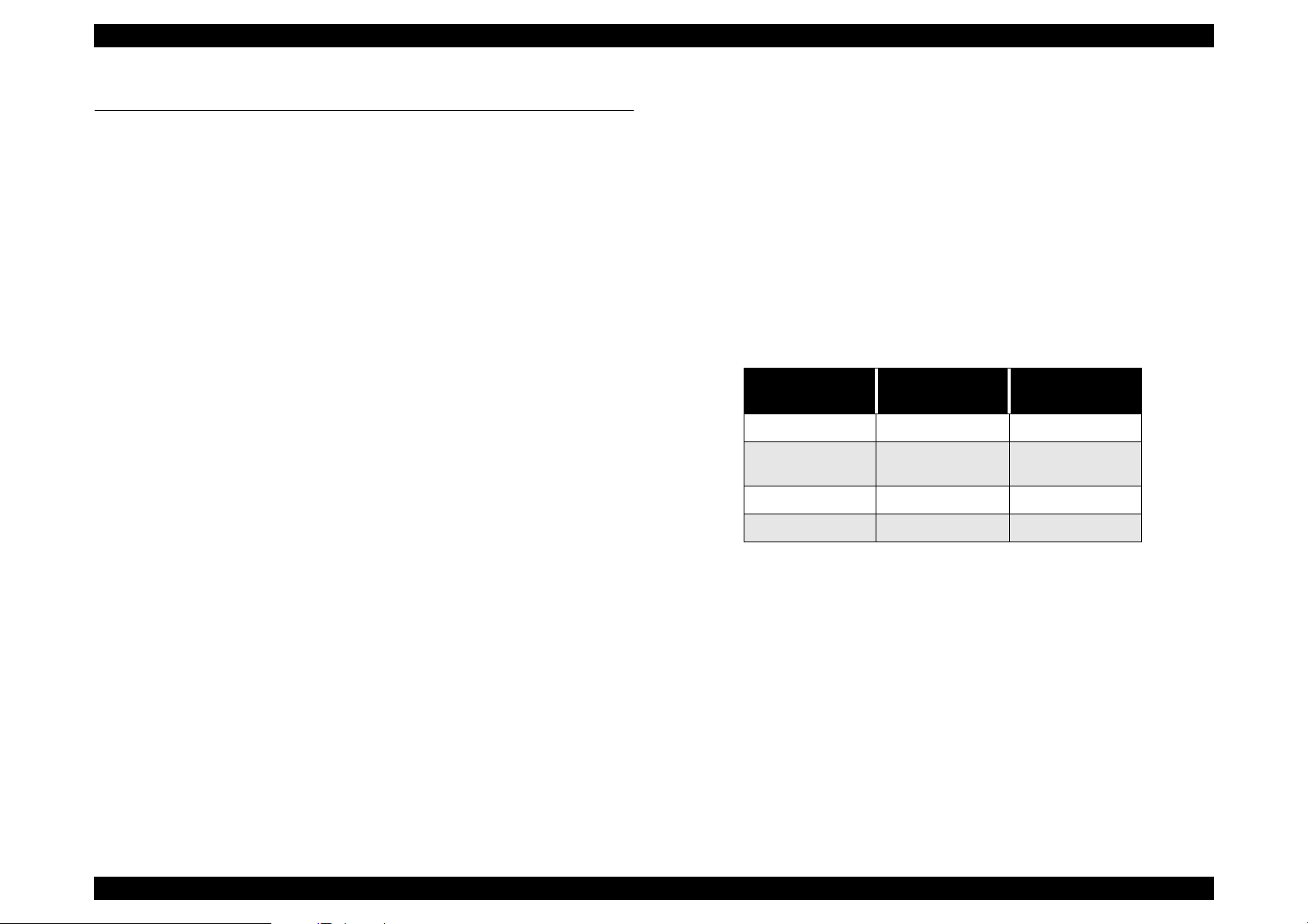
7.6.3 Interface
Connector shape: 8 pin DIN connector (Male)
Figure 7-7. Connector Shape
Pin Assignment
Table 7-14. Pin Assignment
Pin No. Signal I/O
1+5V PWR
I F
Description
2 GND PWR
3+24VPWR
137mm
319mm
4 LOD IN Serial data latch
5GNDPWR
6 SO OUT Serial out data
7 SI IN Serial in data
8 SCK IN Serial clock
Figure 7-6. ADF Size
Appendix Optional Part; ADF 69
Page 70

EPSON Perfection 1640SU Revision A
7.7 ADF: Disassembly
Here explains disassembly procedures of ADF. Unless otherwise specified,
disassembled units or parts can be reassembled by reversing the disassembly
procedure.
7.7.1 B81314 Main Board Removal
1. Remove the tray.
2. Flip over the ADF so that you can see the bottom of the ADF. Remove 2
screws (silver, P-tite, M3x6) securing the cover of the bottom of the main
board.
Remove 5 cables.
Figure 7-9. Removing the B81314 Board (1)
Remove
2 screws
Figure 7-8. 2 screws on the back of ADF
3. Disconnect 5 cables from B81314 Main board and remove 5 screws (gold,
P-tite).
4. Remove B81314 main board.
Remove
5 screws.
Figure 7-10. Removing B81314 Board (2)
Appendix ADF: Disassembly 70
Page 71

EPSON Perfection 1640SU Revision A
7.7.2 ASF Part
1. Remove 6 cables from the B81314 Main Board.
2. Open the cover and remove a guide bar. Also, disengage right
and left connections of the interior paper guide and remove the cover from
the case shaft.
ASF release lever
Open the cover and remove
the guide bar (black)
Figure 7-11. Guide Removal
3. Open the ASF release lever.
Open
Remove 2 screws and
2 metal parts.
Figure 7-12. Removing Screws and Metal Parts
4. Remove 2 screws (gold, P tite) and 2 metal parts.
Appendix ADF: Disassembly 71
Page 72

EPSON Perfection 1640SU Revision A
7.7.2.1 Disassembly of ASF Part
1. In order to remove the cover, remove 2 screws (black, CB + washer)
located on the right and left edges of the front cover. Flip over and remove
2 screws (gold, P-tite+ washer) from the bottom, then remove the cover.
Remove 2
black screws
Figure 7-13. Removing Screws (1)
2. Remove 4 screws (gold, P-tite + washer), and remove Motor/ Solenoid
Assembly.
C A U T I O N
Since one of the screws** is used as a stopper at the
slide gear part, be careful when removing the screw
because all gears will jump out.
(See figure7-16 on the next page)
Figure 7-15. Removing Motor/Solenoid Assembly
Remove 2 screws
Figure 7-14. Removing screws (2)
Appendix ADF: Disassembly 72
Page 73

EPSON Perfection 1640SU Revision A
7.7.2.2 Gear Frame
1. Release the lock of 2 shaft supports (white plastic parts) and remove 2
3 screws
One screw
See “Note” on
previous page
screws.
Release the lock of
shaft support (white)
Figure 7-16. Motor/Solenoid Assembly Removal
These
parts are
installed at
the shaft in
this order.
Figure 7-17. Inside Parts
Remove 2 screws
Figure 7-18. Roller Removal (1)
2. Remove the roller shaft (front).
Remove the
roller shaft
Figure 7-19. Roller Removal (2)
Appendix ADF: Disassembly 73
Page 74

EPSON Perfection 1640SU Revision A
3. Insert (-) driver into the gap shown in the figure below, and remove the
white standard board by pushing it to the arrowed direction.
Slide the white standard board to
this direction strongly and release
the hook.
Removed white
standard
White
standard
board
Insert (-) driver into
this gap and push
Figure 7-20. Removing the white standard board (1)
4. Release the lock of the shaft supports at right and left and remove the
roller shaft (rear).
Release the lock of
shaft supports.
Figure 7-21. Removing the white standard board (2)
Remove the
roller shaft (rear)
Figure 7-22. Roller Removal
Appendix ADF: Disassembly 74
Page 75

EPSON Perfection 1640SU Revision A
5. Remove one metal part and 3 screws. (When you remove one of the
screws, push the release lever to the arrowed direction.
Remove3
screws
Remove these 4 gears.
Remove this
screw after
moving this lever
Remove this
metal part
F i g u r e 7 - 2 3. Re m o v i n g g e a rs
6. Remove 4 gears. One of the gear is fixing the hook to the PF roller shaft.
7. Remove 2 screws (gold, P-tite). After removing screws, remove the black
plastic frame.
Remove this black
Remove 2
screws
plastic frame after
removing screws
Figure 7-24. Removing the plastic frame
Appendix ADF: Disassembly 75
Page 76

EPSON Perfection 1640SU Revision A
7.7.3 Disassembling the ASF and Frame
1. After moving the paper edge guide in the direction of the arrow, remove the
screw (silver, P-tite + washer). Remove the two screws shown in Figure
7-18 now if they have not yet been removed.
2. Separate ASF Assembly and frame part.
Remove a screw
Figure 7-25. Disassembly of ASF and Frame (1)
Move the paper
edge guide
ASF
Assembly
Frame
Part
Figure 7-26. Disassembly of ASF and Frame (2)
Appendix ADF: Disassembly 76
Page 77

EPSON Perfection 1640SU Revision A
3. Remove the actuator and PE board assembly.
Figure 7-27. Removing Actuator and PE Board Assembly (1)
PE Board
Assembly
Actuator
Figure 7-28. Removing Actuator and PE Board Assembly (2)
Appendix ADF: Disassembly 77
Page 78

EPSON Perfection 1640SU Revision A
7.8 Parts List of ADF
Table 7-15. ADF Parts List
Number Name
101 MAT
102 DOUBLE SIDE TAPE,215X5
108 COVER,LOWER
109 LEVER,OPEN
110 SHEET,INSULATUIIN
111 FRAME,BASE
112 HOLDER,HINGE,R
113 GUIDE,HINGE
114 HOLDER,HINGE,L
115 METAL FITTINGS,RELEASE
116 MOUNTING PLATE,PAPER GUIDE
117 SHEET GUIDE;C
118 SHEET GUIDE,ADAPTER
119 ROLLER,DRIVEN,EJ
120 ROLLER,EJ,SUPPORT
121 SHAFT,ROLLER,EJ
122 COMPRESSION SPRING,3.91
123 ROLLER,DRIVEN,PF
124 SHAFT,ROLLER,PF
125 PRESSING PLATE,PF
126 PAPER GUIDE,PF
127 PAPER GUIDE,LD
128 COVER,TOP
129 HARNESS,ASF
130 CLAMP,CABLE,3
131 HARNESS
132 C.B.P(P1),3X8,F/ZN
133 C.B.P-TITE(P2)SCREW,3X10,F/ZN
134 C.B.P.SCREW,4X12,F/ZN
Table 7-15. ADF Parts List
Number Name
135 C.B.P-TITE,3X10,F/NI
136 BOARD ASSY.,MAIN
137 SHEET ADAPTER ASSY
138 WIRE,STOPPER
139 SHEET GUIDE;B
140 GROUND ING PLATE
141 ANTI-STATIC BRUSH;B
142 EARTH WIRE,A
201 FRAME,ASF
202 HOPPER
203 EDGEGUIDE
204 CORK
205 LABEL,EDGEGUIDE
206 LEVER,FASTEN,EDGEGUIDE;B
207 EXTENSION SPRING,0.088
208 LEVER,PE,FRONT
209 LEVER,HOPPER,RELEASE
210 DETECTOR,HP;C
211 SLIDER,EDGEGUIDE
212 PAD,BREAK,EDGE GUIDE
213 COMPRESSION SPRING,3.23
214 TORSION SPRING,41.2
215 LEVER,BRAKE
216 PAD,BREAK
217 HARNESS,HP
218 CIRCUIT ASSY,PE
219 HARNESS,PE,FRONT
220 C.B.P.SCREW,4X12,F/ZN
221 C.B.P-TITE(P2)SCREW,3X10,F/ZN
301 FRAME,GEAR
302 FRAME,MOTOR
303 MOTOR ASSY.,ADF
Appendix Parts List of ADF 78
Page 79

EPSON Perfection 1640SU Revision A
Table 7-15. ADF Parts List
Number Name
304 SOLENOID ASSY.
305 DAMPER,CR
306 SPACER,SOLENOID
307 FLANGE
308 COMBINATION GEAR,15.2,24
309 U-TYPE SPRING WASHER,5.2X0.4X10,S/NA
310 COMPRESSION SPRING,0.39
311 COMBINATION GEAR,17.6,22
312 COMBINATION GEAR,9.6,22.8
313 SUPR GEAR,18.4
314 SPUR GEAR,27.2
315 SUPR GEAR,20
316 SPACER,3X6.5,ZMC
317 CLIP
318 MOUNTING PLATE,FRONT
320 C.B.P-TITE(P2)SCREW,3X10,F/ZN
321 C.B.P.SCREW,4X12,F/ZN
322 C.B.P(P1),3X8,F/ZN
323 C.B.(P2)SCREW,3X5,F/ZN
324 C.B.B(P2),2.9X12,F/ZN
325 PLANE WASHER,4.5X0.5X8,L/NA
326 C.B.(P2)SCREW,3X8,F/ZN
327 PLAIN WASHER
401 BASE,WHITE
402 SHEET,WHITE
403 SHAFT,RELEASE
404 ANTI-STATIC BRUSH;C
405 PAPER GUIDE,MAIN
406 HOUSING
407 LEVER,PE,REAR
408 TORSION SPRING,0.22
409 ROLLER,GUIDE
Table 7-15. ADF Parts List
Number Name
410 CIRCUIT ASSY,PE
411 MOUNTING PLATE,REAR,L
412 CLIP
413 MOUNTING PLATE,REAR,R
414 ROLLER ASSY.,PF;B
415 ROLLER ASSY.,EJ
416 BUSHING,6
417 LEVER,RELEASE
418 TORSION SPRING,125.17,L
419 TORSION SPRING,125.17,R
420 LEVER,RELEASE;B
421 PLANE WASHER,4.5X0.5X8,L/NA
422 C.B.S.(P2),3X6,F/ZB
423 C.B.P-TITE(P2)SCREW,3X10,F/ZN
424 RETAINING RING
425 ALUMINUM FOIL TAPE,80X7
426 EARTH WIRE,B
427 MOUNTING PLATE,PAPER GUIDE
428 C.B.P-TITE SCREW,3X6,F/ZN
501 SHAFT,ROLLER,LD
502 PAPER LOADING ASSY.,LEFT
503 PAPER LOADING ASSY.,RIGHT
504 ROLLER,ASSY.,LD,LEFT
505 ROLLER,ASSY.,LD,RIGHT
506 COVER,ROLLER,LD,LEFT
507 COVER,ROLLER,LD,RIGHT
508 COMPRESSION SPRING,1.66
509 HOLDER,SHEET,PAPER FEED
510 SHEET,PF
511 BUSHING,FASTEN,SHAFT,LEFT
512 LEVER,HOPPER,RELEASE
513 WHEEL,DETECT
Appendix Parts List of ADF 79
Page 80

EPSON Perfection 1640SU Revision A
7.9 ADF Exploded Diagram
N
O
L
129
118
117
138
139
101
133
M
133
138
133
131
113
130
114
133
102
115
132
134
116
133
119
122
120
120
119
122
111
134
121
120
119
122
112
123
124
132
127
123
113
125
133
124
115
132
125
141
132
140
142
123
133
109
116
124
132
128
133
126
125
123
124
132
110
135
O
N
J
I
B
M
133
E
136
133
108
137
135
Perfection 1640SU Office ADF No.07 Rev.01 10237
Figure 7-29. ADF Exploded Diagram (1)
Appendix ADF Exploded Diagram 80
Page 81

EPSON Perfection 1640SU Revision A
204
204
207
219
206
209
208
207
206
C
205
220
210
D
201
E
218
221
P
214
A
B
216
215
212
211
213
217
203
202
A
Perfection 1640SU Office ADF No.08
Rev.01 10237
Figure 7-30. Exploded Diagram (2)
Appendix ADF Exploded Diagram 81
Page 82

EPSON Perfection 1640SU Revision A
322
306
303
324
327
316
307
305
317
324
316
324
305
J
316
320
305
322
K
302
H
326
318
323
313
321
325
312
311
312
314
320
312
325
311
315
320
H
301
F
G
304
307
I
308
309
310
Perfection 1640SU Office ADF No.09
Rev.01 10237
Figure 7-31. Exploded Diagram (3)
Appendix ADF Exploded Diagram 82
Page 83

EPSON Perfection 1640SU Revision A
421
423
424
F
G
417
416
418
402
411
424
D
403
409
L
410
423
407
412
404
408
409
405
427
428
425
422
422
K
426
406
413
423
414
412
415
419
401
420
421
Perfection 1640SU Office ADF No.10
Rev.01 10237
416
Figure 7-32. Exploded Diagram (4)
Appendix ADF Exploded Diagram 83
Page 84

EPSON Perfection 1640SU Revision A
508
C
503
505
509
510
506
504
507
502
509
510
508
501
511
P
512
513
Perfection 1640SU Office ADF No.11 Rev.01 10237
Figure 7-33. Exploded Diagram (5)
Appendix ADF Exploded Diagram 84
 Loading...