

Epson 1600, 1600 Pro Service manual
EPSON
EPSON
EPSON France S.A.
Expression 1600
SERVICE MANUAL
PRODUIT
®
SERVICE MANUAL
SERVICE MANUAL
SERVICE MANUALSERVICE MANUAL
Color image scanner
EPSON Expression 1600/1600 Pro
SESC99007

EPSON Expression 1600/1600 Pro Revision A
Notice:
All rights reserved. No part of this manual may be reproduced, stored in a retrieval system, or transmitted in any form or by any means, electronic, mechanical,
photocopying, recording, or otherwise, without the prior written permission of SEIKO EPSON CORPORATION.
The contents of this manual are subject to change without notice.
All effort have been made to ensure the accuracy of the contents of this manual. However, should any errors be detected, SEIKO EPSON would greatly appreciate being
informed of them.
The above not withstanding SEIKO EPSON CORPORATION can assume no responsibility for any errors in this manual or the consequences thereof.
EPSON is a registered trademark of SEIKO EPSON CORPORATION.
General Notice: Other product names used herein are for identification purpose only and may be trademarks or registered trademarks of their
respective owners. EPSON disclaims any and all rights in those marks.
Copyright © 1999 SEIKO EPSON CORPORATION. Printed in Japan.
2

EPSON Expression 1600/1600 Pro Revision A
PRECAUTIONS
Precautionary notations throughout the text are categorized relative to 1)Personal injury and 2) damage to equipment.
DANGER
WARNING
The precautionary measures itemized below should always be observed when performing repair/maintenance procedures.
Signals a precaution which, if ignored, could result in serious or fatal personal injury. Great caution should be exercised in performing procedures preceded by
DANGER Headings.
Signals a precaution which, if ignored, could result in damage to equipment.
DANGER
1. ALWAYS DISCONNECT THE PRODUCT FROM THE POWER SOURCE AND PERIPHERAL DEVICES PERFORMING ANY MAINTENANCE OR REPAIR
PROCEDURES.
2. NOWORK SHOULD BE PERFORMED ON THE UNIT BY PERSONS UNFAMILIAR WITH BASIC SAFETY MEASURES AS DICTATED FOR ALL ELECTRONICS
TECHNICIANS IN THEIR LINE OF WORK.
3. WHEN PERFORMING TESTING AS DICTATED WITHIN THIS MANUAL, DO NOT CONNECT THE UNIT TO A POWER SOURCE UNTIL INSTRUCTED TO DO
SO. WHEN THE POWER SUPPLY CABLE MUST BE CONNECTED, USE EXTREME CAUTION IN WORKING ON POWER SUPPLY AND OTHER ELECTRONIC
COMPONENTS.
WARNING
1. REPAIRS ON EPSON PRODUCT SHOULD BE PERFORMED ONLY BY AN EPSON CERTIFIED REPAIR TECHNICIAN.
2. MAKE CERTAIN THAT THE SOURCE VOLTAGES IS THE SAME AS THE RATED VOLTAGE, LISTED ON THE SERIAL NUMBER/RATING PLATE. IF THE
EPSON PRODUCT HAS A PRIMARY AC RATING DIFFERENT FROM AVAILABLE POWER SOURCE, DO NOT CONNECT IT TO THE POWER SOURCE.
3. ALWAYS VERIFY THAT THE EPSON PRODUCT HAS BEEN DISCONNECTED FROM THE POWER SOURCE BEFORE REMOVING OR REPLACING PRINTED
CIRCUIT BOARDS AND/OR INDIVIDUAL CHIPS.
4. IN ORDER TO PROTECT SENSITIVE MICROPROCESSORS AND CIRCUITRY, USE STATIC DISCHARGE EQUIPMENT, SUCH AS ANTI-STATIC WRIST
STRAPS, WHEN ACCESSING INTERNAL COMPONENTS.
5. REPLACE MALFUNCTIONING COMPONENTS ONLY WITH THOSE COMPONENTS BY THE MANUFACTURE; INTRODUCTION OF SECOND-SOURCE ICs OR
OTHER NONAPPROVED COMPONENTS MAY DAMAGE THE PRODUCT AND VOID ANY APPLICABLE EPSON WARRANTY.
3

EPSON Expression 1600/1600 Pro Revision A
PREFACE
This manual describes basic functions, theory of electrical and mechanical operations, maintenance and repair procedures of EPSON Expression 1600/1600 Pro. The instructions and
procedures included herein are intended for the experienced repair technicians, and attention should be given to the precautions on the preceding page. The chapters are organized as follows:
CHAPTER 1. PRODUCT DESCRIPTIONS
Provides a general overview and specifications of the product.
CHAPTER 2. OPERATING PRINCIPLES
Describes the theory of electrical and mechanical operations of the product.
CHAPTER 3. TROUBLESHOOTING
Provides the step-by-step procedures for troubleshooting.
CHAPTER 4. DISASSEMBLY AND ASSEMBLY
Describes the step-by-step procedures for disassembling and assembling the
product.
CHAPTER 5. ADJUSTMENTS
Provides Epson-approved methods for adjustment.
CHAPTER 6. MAINTENANCE
Provides preventive maintenance procedures and the lists of Epson-approved
lubricants and adhesives required for servicing the product.
APPENDIX
Provides the following additional information for reference:
• Connector Pin Assignments
• B109 MAIN Board Component Layout
• B109 MAIN Board Circuit Diagram
4

EPSON Expression 1600/1600 Pro Revision A
Revision Status
Revision Issued Date Description
A October 28, 1999 First Release
5

EPSON Expression 1600/1600 Pro Revision A
Contents
PRODUCT DESCRIPTIONS
Features ......................................................................................................... 8
Specifications ................................................................................................. 8
Interfaces...................................................................................................... 10
SCSI Interface ......................................................................................... 10
USB Interface .......................................................................................... 11
IEEE1394 Serial Bus Interface................................................................ 11
Buttons and Lamps....................................................................................... 12
Buttons .................................................................................................... 12
Indicators................................................................................................. 13
Physical Specifications ............................................................................ 13
Scanning Area......................................................................................... 14
Control Codes and Commands .................................................................... 15
Errors............................................................................................................ 16
OPERATING PRINCIPLES
Mechanism Operating Principles.................................................................. 18
Fixed Type Two Focuses Mechanism..................................................... 18
Control Circuit Operation .............................................................................. 19
TROUBLESHOOTING
Overview....................................................................................................... 24
DISASSEMBLY AND ASSEMBLY
“GLASS ASSEMBLY, FOCUS” Removal................................................ 30
“MOTOR ASSEMBLY, FOCUS” Removal .............................................. 31
Bottom Plate Removal ............................................................................ 31
B109 PSH Board Removal...................................................................... 32
B109 SUB-B Board Removal .................................................................. 32
B109 MAIN Board Removal .................................................................... 33
B109 SUB Board Removal...................................................................... 34
ADJUSTMENT
Overview ...................................................................................................... 36
MAINTENANCE
Overview ...................................................................................................... 38
APPENDIX
Overview ...................................................................................................... 40
Interconnection of the Major Components .............................................. 40
Connector Summary ............................................................................... 41
B109 MAIN Board Connector Pin Assignment........................................ 42
Component Layout ....................................................................................... 47
Exploded Diagrams and Parts List ............................................................... 48
Exploded Diagrams ................................................................................. 48
Parts List ................................................................................................. 51
Circuit Diagrams ........................................................................................... 52
Overview....................................................................................................... 28
Tools........................................................................................................ 28
Disassembly Procedures .............................................................................. 29
LED Board Removal................................................................................ 29
Operate Switch Board Removal .............................................................. 29
6

PRODUCT DESCRIPTIONS
CHAPTER
1

EPSON Expression 1600/1600 Pro Revision A
1.1 Features
This specifications are applied to the EPSON Color Image Scanner Expression 1600/1600
Pro.
The best Color Image Scanner for both graphics and office usage.
Maximum document size: 8.5 x 11.7 inches (216 x 297 mm)
Scanning speed: Line art =3.1mS/line
Gray scale=3.1mS/line
Color=9.2mS/line
(1600dpi, Draft Mode)
High image quality
Scanning resolution: 1600dpi(main) x 3200dpi’sub)
Pixel depth: In 12bit, Out 1-12bit
Max. OD Value: 3.3D
Focus control: 2position
Many types of IF available
SCSI (Standard)
USB (Standard)
IEEE 1394 Board (Optional)
1.2 Specifications
GENERAL SPECIFICATIONS
Product type: Flatbed Color Image Scanner
Sub-scanning method: Movement of the Scanner-Head
Photoelectric device: Alternative 6-line CCD (40800 pixel)
Maximum document size: 8.5 x 11.7 inches (216 x 297 mm)
Maximum picture element: 13,600(main) x 18,720(sub) pixels (1600dpi)
Scanning Resolution:
Main: 1600dpi (Optical resolution by 6 line CCD with
40800 pixel)
Sub: 3200dpi with micro step
Output resolution: 50 ~ 4800dpi (1dpi step)
Pixel depth: In 12-bit / pixel, Out 1-12bit/pixel
Color separation method: By the color filter of CCD
Zoom: 50 ~ 200% (1% step)
Scanning speed (1600dpi,Draft Mode):
Start bottom
Starts scanning (In case of network connection)
Wakes up scanner application software (In case of local connection)
Command Level
ESC/I-B8
FS
Option
ADF (Same as the GT-9600’s)
TPU (Same as the GT-9600’s, but Film holder is added)
IEEE 1394 Board
Color: 9.2ms/line
Monochrome: 3.1ms/line
Command level: ESC/I-B8, FS
Image processing functions:
Gamma correction: CRT (A, B)
Printer (A, B, C)
User Defined Table
Color correction: Impact Dot Printer
Thermal Printer
Ink Jet Printer
CRT Display
User Defined Matrix
PRODUCT DESCRIPTIONS Features 8

EPSON Expression 1600/1600 Pro Revision A
Brightness: 7 levels
Line art: Fixed threshold
TET
Halftone: Error diffusion (A, B, C)
Dither (A, B, C, D)
User defined dither (A, B)
Area separation: AAS
Interface:
SCSI (50-contact high-density connector, standard)
USB (Type-B Receptacle Connector, standard)
IEEE 1394 Serial Bus Interface (Optional)
Light source: Xenon gas fluorescent lamp
ELECTRICAL SPECIFICATIONS
Rate voltage: Universal Power Supply
AC100-120V
AC220-240V
Input voltage: AC100-120V±10%
AC220-240V±10%
SAFETY, EMC, EPA
Safety: UL1950 (+D3): USA
CSA C22.2 NO.950 (+D3): Canada
EN60950 (VDE)
IEC950 (ROSTEST, PSB)
EMC: FCC Part15 Subpart B Class B: USA
CSA C108.8 Class B: Canada
AS/NZS3548 Class B: Australia
CISPR Pub22 Class B: Korea
CNS13438 Class B: Taiwan
CE marking:
Low Voltage Directive 73/23/EEC EN60950
MC Directive 89/336/EEC EN55022 Class B
EN61000-3-2
EN61000-3-3
EN 50082-1
IEC 801-2
IEC 801-3
IEC 801-4
EPA: Energy Star ProgramAPI=On
Rated current: 0.8 A (Input AC110V)
0.4 A (Input AC220V)
Rated frequency range: 50-60Hz
Input frequency range: 49.5-60.5Hz
Power consumption: Approx.30 W (without optionan unit)
Approx.50 W (without optionan unit)
Approx.10 W (without optionan unit)
Insulation resistance: 10MW at 500VDC
(between AC line and chassis)
Dielectric strength: AC1.2kV, 1min
(between AC line and chassis)
RESISTANCE TO ELECTRIC NOISE
Static electricity: Panel 10kV
Metal 7kV/150pF, 150W
ENVIRONMENTAL CONDITIONS
Temperature: Operating 5 ~ 35°C
Storage -25 ~ 60°C
Humidity: Operating 10 ~ 80%, no condensation
Storage 10 ~ 85%, no condensation
RELIABILITY
Main unit: MCBF 100,000 cyclear CSA C108.
PRODUCT DESCRIPTIONS Specifications 9
EPSON Expression 1600/1600 Pro Revision A
OPERATING CONDITIONS
Dust:
Illumination:
DOCUMENT
Reflective type:
Ordinary office or home conditions. Extreme dust
should be avoided.
Operation under direct sunlight or near strong light
source is not guaranteed and should be avoided.
Documents which has a smooth surface such as a
printing and photograph.
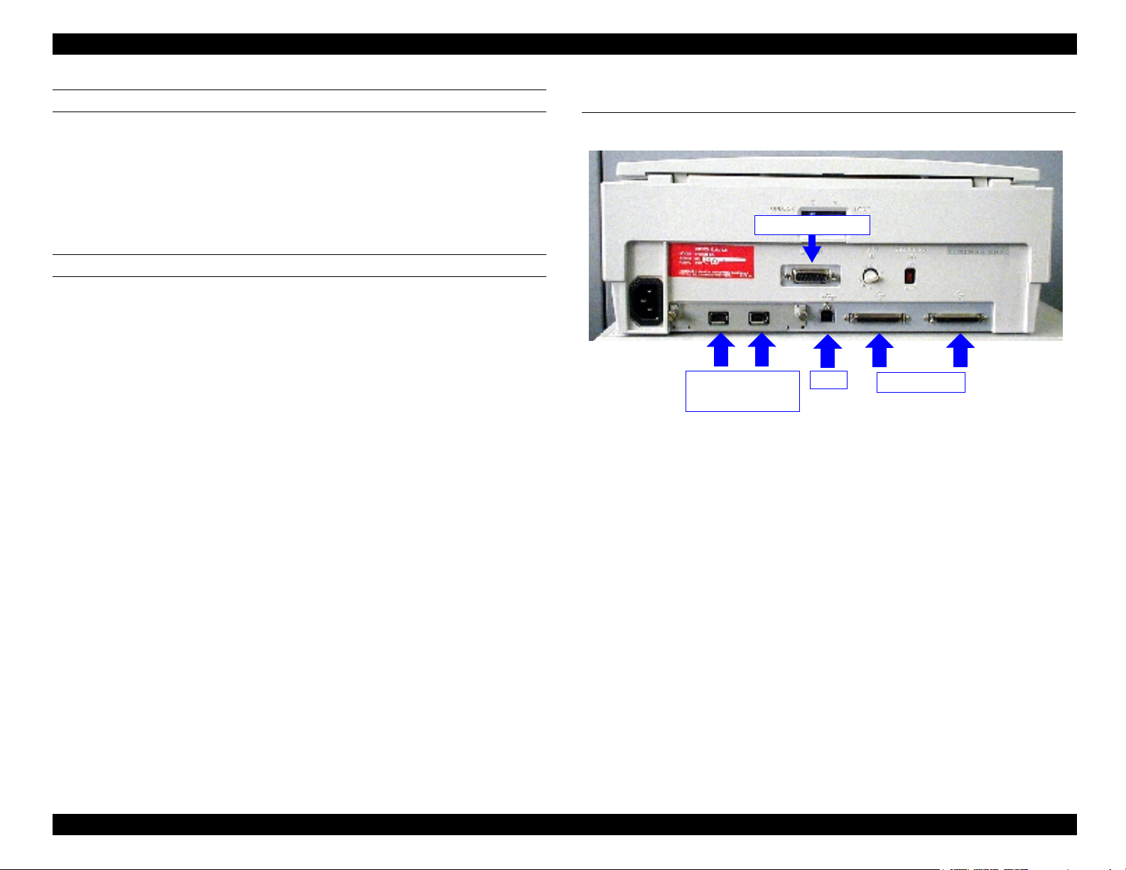
1.3 Interfaces
This section includes the specifications for the interfaces equipped with this scanner.
ADF/TPU Connector
IEEE1394 Interface
(Optional)
Figure 1-1. Interface Location
1.3.1 SCSI Interface
USB
SCSI Interface
See the GT-10000 Service Manual / Section 1.3.1 for the specifications and functions of the
SCSI Interface equipped with the Expression 1600/1600 Pro.
PRODUCT DESCRIPTIONS Interfaces 10

EPSON Expression 1600/1600 Pro Revision A
1.3.2 USB Interface
Basic specifications
Device:
Class:Vender specific
Sub class:Vender specific
Protocol:Vender specific
Maximum packet size for end point 0:0x04B8
Product ID:0x0107
Number of formation:1
Configuration:
Alternate setting value:None
Number of end points:2
Class:Vender specific
Sub class:Vender specific
Protocol:Vender specific
End point 1:Bulk IN transmission
Maximum packet size: 64 byte
End point 2:Bulk OUT transmission
Maximum packet size: 64 byte
String descriptor:Manufacturer: EPSON
Product name: Expression 1600/1600 Pro
Electrical specifications: Compliant with the high speed mode
(12Mbps)
1.3.3 IEEE1394 Serial Bus Interface
Refer to the IEEE 1394 optional board service manual.
Connector: B receptacle (1)
Pin arrangement, Pin assignment:
Table 1-1. USB Pin Assignment
Pin No. Signal
2 1
3 4
1VCC
2 -Data
3-Data
4 GND
PRODUCT DESCRIPTIONS Interfaces 11
EPSON Expression 1600/1600 Pro Revision A
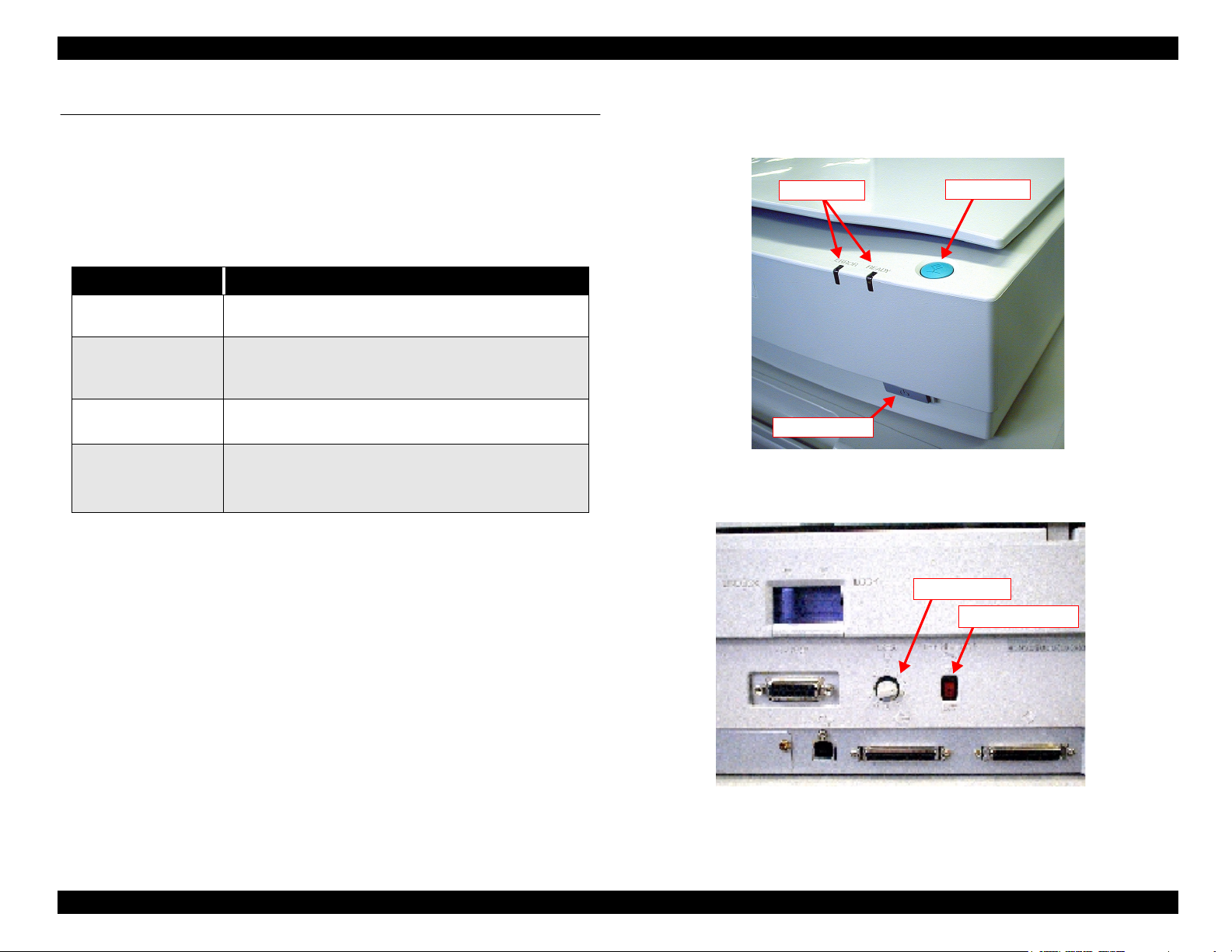
1.4 Buttons and Lamps
See the figures below for the locations of the buttons and switches.
1.4.1 Buttons
The buttons equipped with this scanner and their functions are as shown below:
Table 1-2. Buttons and Functions
Buttons Functions
Operate switch
Start bottom
SCSI ID switch (Rotary
switch)
Terminator switch Sets the SCSI terminator.
• Turns the scanner ON and OFF.
• Initializes the scanner when the scanner power is turned on.
• Starts scanning (In case of network connection)
• Starts scanner application software (In case of local
connection)
• 0 ~ 7: SCSI ID (Factory default ID=2)
• Others: Reserved
• ON: Terminator on (Default)
• OFF: Terminator off
LED Lamps
Operate Switch
Start Button
Figure 1-2. Location of the Button and Switches
SCSI ID Switch
Terminator Switch
Figure 1-3. Locations of the SCSI/Terminator Switches
PRODUCT DESCRIPTIONS Buttons and Lamps 12
EPSON Expression 1600/1600 Pro Revision A
1.4.2 Indicators
The table below lists the indicator lamps equipped with this scanner. (See Figure 1-1 for the
location.)
Table 1-3. Lamps and their Functions
Lamps Functions
READY
(Greed LED)
ERROR
(Red LED)
The scanner shows several error conditions by turning on/off each lamp as shown in the
table below:
Table 1-4. Error Indication by LEDs
READY (Green LED)
Lights up Lights up Command Error
• Lights up when the scanner is ready to send and
receive data.
• During scanning, goes on and off in accordance with
data transmission.
• Blinks in combination with the ERROR LED when an
error occurs.
Indicates an error condition.
ERROR (Red LED)
Error Type
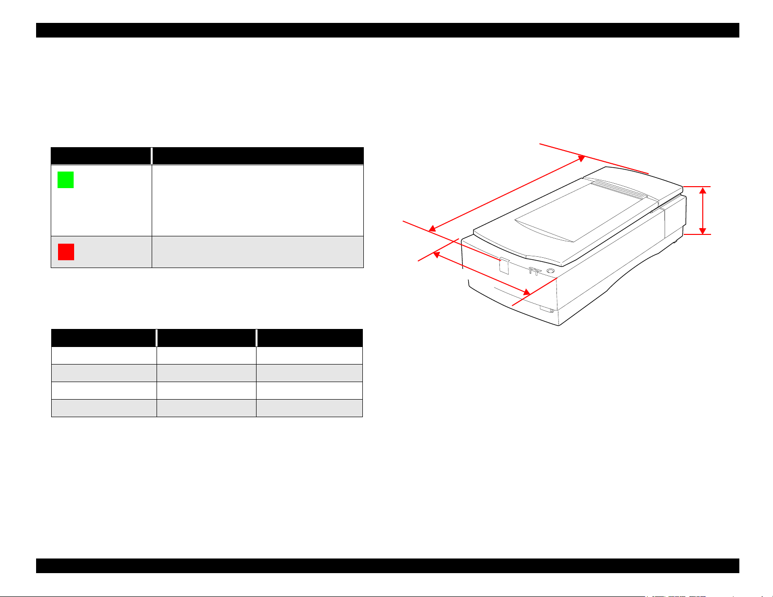
1.4.3 Physical Specifications
External view
m
m
2
6
5
3
3
2
m
m
Figure 1-4. External View of the Expression 1600/1600 Pro
133 mm
Off Blinks Interface Error
Blinks Blinks Fatal Error
Off Off Option Error
Dimensions: 332 x 562 x 133 mm (W x D x H)
Weight: Approximately 8.5kg
PRODUCT DESCRIPTIONS Buttons and Lamps 13
EPSON Expression 1600/1600 Pro Revision A
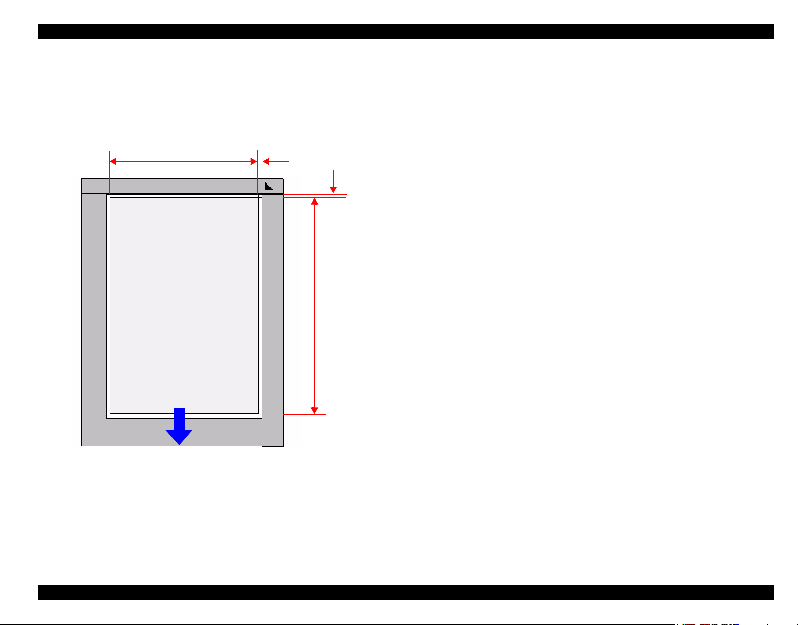
1.4.4 Scanning Area
The effective scanning area of the scanner is 216 x 297 mm (main scan x sub scan). See the
figure below:
216 mm
Front
1.0 - 1.5 mm
1.6 - 0.5 mm
297 mm
Figure 1-5. Maximum Scanning Area
PRODUCT DESCRIPTIONS Buttons and Lamps 14
EPSON Expression 1600/1600 Pro Revision A
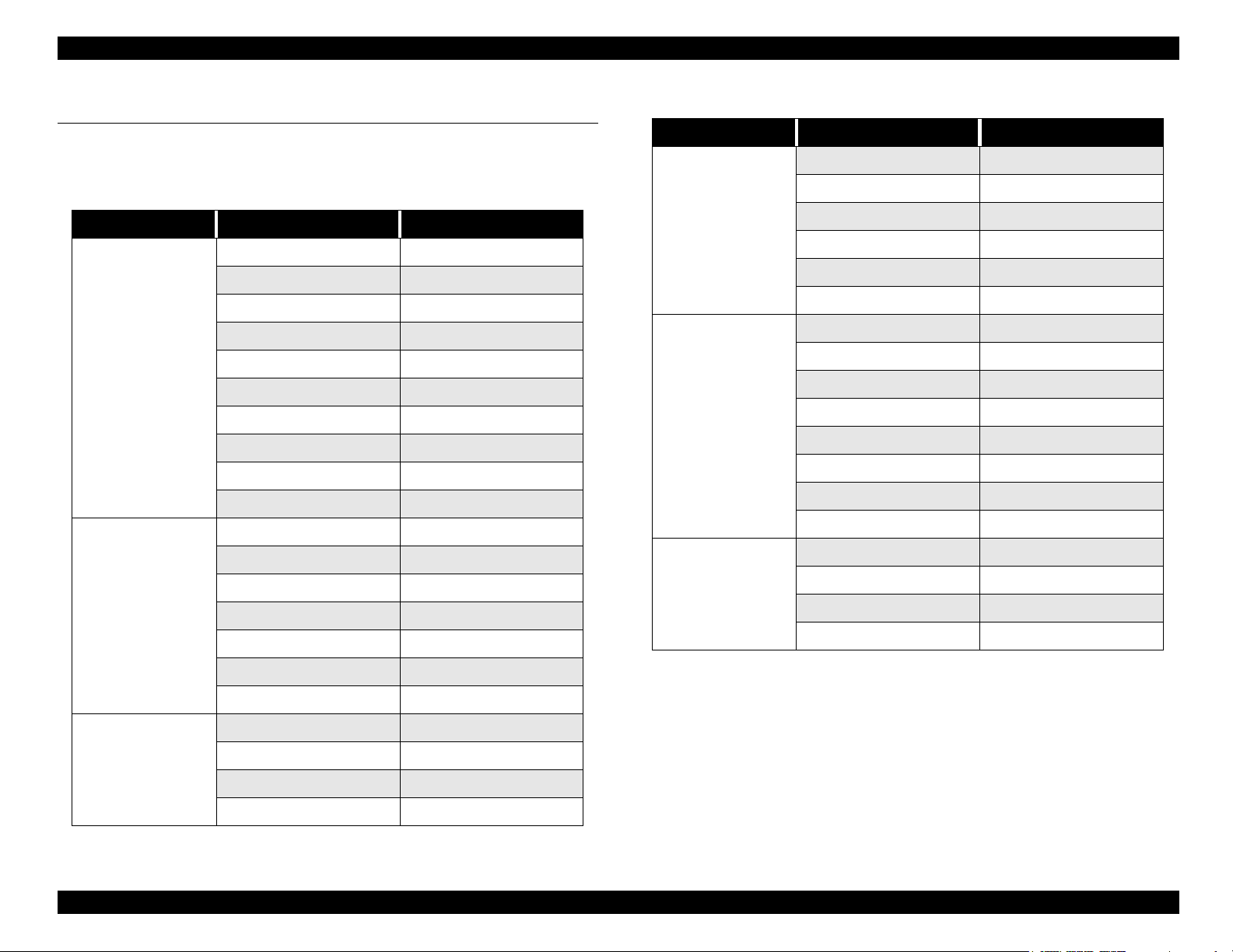
1.5 Control Codes and Commands
The control codes and commands of the scanner are as listed in the following table:
Table 1-5. Control Code Commands
Classification Name Code
Command
Set data form
ID request ESC I
status request ESC F
extended status request ESC f
request command parameters ESC S
start scanning ESC G
Push Button status request ESC !
extended ID request FS I
scanner status request FS F
scanning parameter request FS S
start new scanning FS G
set data format ESC D i
set resolution ESC R n1 n2
set zooming ESC H i1 i2
set scanning area ESC A n1 n2 n3 n4
set color ESC C i
Table 1-5. Control Code Commands (continued)
Classification Name Code
Image disposition
Support, and others
Control
set half-tone processing ESC B i
set auto area segmentation ESC s i
down load dither pattern ESC b i j d[j^2]
set color correction ESC M i
down load color correction ESC m d[9]
set threshold ESC t i
set scanning mode ESC g i
initialize ESC @
set line counter ESC d i
option control ESC e i
set film type ESC N i
set focus position ESC p i
request focus position ESC q
eject paper FF
normal response ACK
abnormal response NACK
stop scanning CAN
header STX
set mirroring ESC K i
set scanning parameter FS W
Correction
set brightness ESC L i
set gamma correction ESC Z i
down load gamma table ESC z i d[256]
set sharpness control ESC Q i
PRODUCT DESCRIPTIONS Control Codes and Commands 15

EPSON Expression 1600/1600 Pro Revision A
1.6 Errors
COMMAND ERROR
[Cause] Unidentified command is detected.
[Disposition] The scanner sends NACK and waits for the next command. When the scanner
receives a wrong command or parameter, it disregards a value and
maintains the former value.
[Indicator] READY LED lights up.
ERROR LED lights up.
[Remedy] The error condition is cleared when the scanner receives a correct command.
INTERFACE ERROR
[Cause] Wrong operation in the communication procedure is detected.
In case of SCSI, a time-out error occurred.
[Disposition] The lamp goes off and the operation stops.
[Indicator] READY LED goes off.
ERROR LED blinks.
[Indicator] READY LED blinks.
ERROR LED blinks.
[Remedy] Turn the scanner off and then back on.
Send Initialize command code (ESC @) to the scanner.
Complete BUS DEVICE RESET message in SCSI.
The RESET signal of SCSI is asserted.
[Acceptable commands] ESC F, ESC f, ESC @, FS F
OPTION ERROR (In Case Option Unit is Installed)
[Cause] Unit cover is open.
Paper empty condition
[Disposition] The bit7 of the status byte is set.
[Indicator] READY LED goes off.
ERROR LED goes off.
[Remedy] Remove the cause of the error condition.
[Remedy] Turn the scanner off and then back on.
The RESET signal of SCSI is asserted.
[Acceptable commands] None
FATAL ERROR
[Cause] The lamp is broken.
Power is turned on before removing the transportation lever.
System breakdown.
[Disposition] The lamp goes off and the operation stops.
The bit 7 of the status byte is set.
PRODUCT DESCRIPTIONS Errors 16
 Loading...