

Page 1
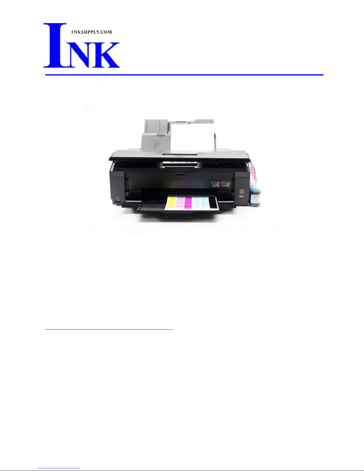
Installation Instructions: Epson 1430 CFS
Prerequisite -
Before starting this installation, you MUST test your printer to make sure it is printing
100% correctly. The best way to do this is to first print a Nozzle pattern, using the
printer utility provided by Epson. Once a perfect nozzle pattern is achieved, print 5
copies of the MIS purge6.tif image using the Plain Paper and 360 dpi settings on the
printer. All 5 pages must print without banding or skipping (white spaces). If your
printer cannot do this, do not install the CFS. If you need to run no more than 3
cleaning cycles, get new cartridges. Do not proceed until you can pass these tests. The
Purge6 image can be found on our Purging Procedures page
(http://www.inksupply.com/purging.cfm
)
S a v e M o n e y a n d I m p r o v e Y o u r P r i n t i n g
MIS Associates Inc 2901 Auburn Rd. Auburn Hills, MI 48326 800-445-8296
http://www.inksupply.com Fax: 248-289-6013 Email: sales@inksupply.com
Page 2
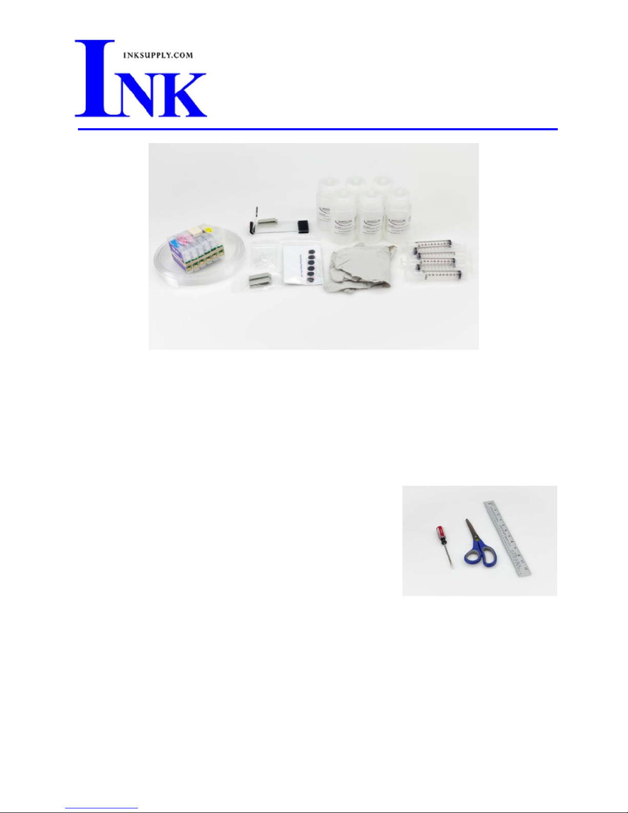
The CFS kit contains:
1x Empty CFS cartridges with tubes.
1x Acrylic Bridge Bracket.
1x Pair gloves.
2x Beige clips.
Installation Instructions
Step 1:
Gather the recommended tools below;
∑ Flat tip screwdriver (1/8" - 1/4")
∑ Scissors
∑ Ruler or Tape Measure
Papers towels and a marker may also be useful.
6x Velcro Dots.
6x Bottles with CFS caps.
6x 10ml syringes (MIS-SYRINGE).
6x Bottom Fill Adapter (MIS-FADP).
Fig. 1
S a v e M o n e y a n d I m p r o v e Y o u r P r i n t i n g
MIS Associates Inc 2901 Auburn Rd. Auburn Hills, MI 48326 800-445-8296
http://www.inksupply.com Fax: 248-289-6013 Email: sales@inksupply.com
Page 3
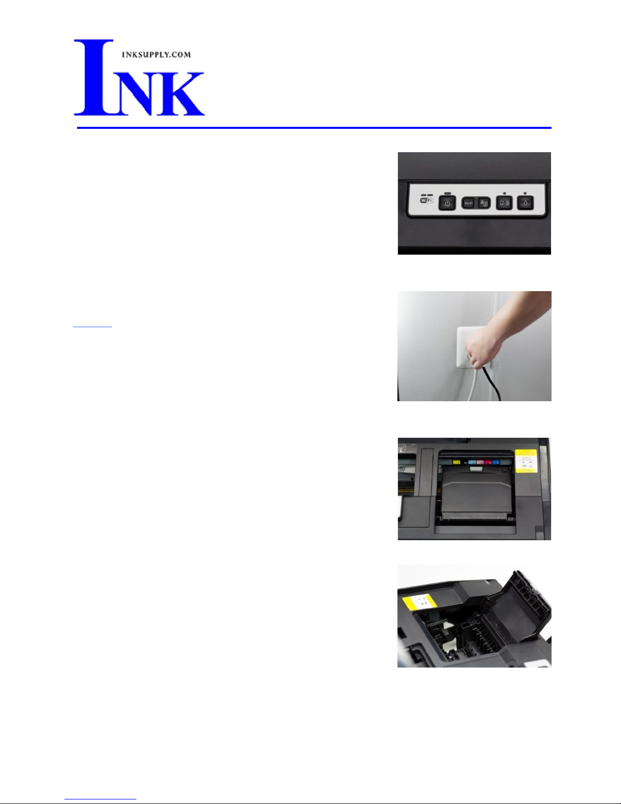
Step 2:
With the printer on, press the ink change button indicated by
the ink droplet. In Fig. 2, the button is located to the far right.
Step 3:
Fig. 2
Without
powering off the printer, unplug the printer from the
wall.
Step 4:
At this point the printer carriage will be centered in the right
opening in the printer top as shown in Fig. 4-1.
The printer carriage lid is removed in 2 parts. The first involves
removing the right most hinge clip, then releasing the left
hinge pivot point.
Fig. 4-2 shows the location of the right clip. Using the
screwdriver as shown in Fig. 4-3, gently pry the clip to the right
to release it. It may take some force as the clip is held in place
by a plastic barb.
Fig. 3
Fig. 4-1
S a v e M o n e y a n d I m p r o v e Y o u r P r i n t i n g
MIS Associates Inc 2901 Auburn Rd. Auburn Hills, MI 48326 800-445-8296
http://www.inksupply.com Fax: 248-289-6013 Email: sales@inksupply.com
Fig. 4-2
Page 4

After the clip is removed, the left side of the cover is easily
removed by inserting the screwdriver into the pivot point and
turning it. This is shown in Fig. 4-3.
Fig. 4-5 shows the cover and the right side clip once they are
removed from the printer.
Fig. 4-3
Fig. 4-4
Step 5:
With the ruler or measuring tape, measure 4.75" from the left
edge of the cross member on the top of the printer as shown in
Fig. 5.
Remove the protective film from the clear acrylic Bridge Bracket
and install it with the right edge of the Bracket lined up with
the edge on the ruler. The Beige Clip on the Bracket should be
on the topside, left as shown if Fig. 5.
S a v e M o n e y a n d I m p r o v e Y o u r P r i n t i n g
MIS Associates Inc 2901 Auburn Rd. Auburn Hills, MI 48326 800-445-8296
http://www.inksupply.com Fax: 248-289-6013 Email: sales@inksupply.com
Fig. 4-5
Fig. 5
Page 5

Step 6:
Install the CFS Assembly into the printer carriage routing the
tubes under the cross member as depicted in Fig. 6.
Step 7:
Fig. 7-1 gives a better angle on the routing of the tubes after
the installation of the CFS Cartridge Assembly.
The 2 Beige Clips are used to align the tubes and will be
installed in such a way as to keep the tubes in line from the
Bridge Bracket to the right edge of the printer.
Fig. 6
As shown in Fig. 7-2, the first Beige Clip is installed on the left
side of the cross member in the top of the printer. Fig. 7-3
shows the location and orientation of the second Beige Clip on
the right side top of the printer. This will create a straight line
for the tubing from the Bridge Bracket on the left to the Beige
Clip on the right.
Before closing the Beige Clips on the tubing, slide the printer
carriage to the far right and adjust the tubing to ensure that
the tubing is not pulled tight at the Bridge Bracket, but also
does not hang loose. You will need to slide the printer carriage
from right to left to ensure that the carriage is able to move
with no restriction or resistance from the tubing. If the tubing
becomes tangled or twisted at any point during the carriage's
travel, the tension will need to be adjusted.
Fig. 7-1
Fig. 7-2
Fig. 7-3
S a v e M o n e y a n d I m p r o v e Y o u r P r i n t i n g
MIS Associates Inc 2901 Auburn Rd. Auburn Hills, MI 48326 800-445-8296
http://www.inksupply.com Fax: 248-289-6013 Email: sales@inksupply.com
Page 6

Too Tight Correct Too Loose
Step 8:
Pour the ink from each of your ink bottles into the
corresponding CFS Bottle. This step is very important as
mixing up the inks will irreparably contaminate the CFS
Assembly.
Step 9:
Attach each of the CFS Bottles to the printer using the included
Velcro Dots. To fit all six bottles the first bottle must be
installed at the very front edge of the printer.
From Front to Back the bottle order is as follows;
Cyan - Magenta - Lt. Magenta - Lt. Cyan - Black - Yellow
Fig 8
Fig. 9
S a v e M o n e y a n d I m p r o v e Y o u r P r i n t i n g
MIS Associates Inc 2901 Auburn Rd. Auburn Hills, MI 48326 800-445-8296
http://www.inksupply.com Fax: 248-289-6013 Email: sales@inksupply.com
Page 7

Step 10:
Verify, from Front to Back the bottle order is as follows;
Cyan - Magenta - Lt. Magenta - Lt. Cyan - Black - Yellow
Next, split the excess tubing back to the right most Beige Clip.
Route the front most tube to the Cyan Bottle and using the
scissors, snip the tuba and plug it onto the Cyan Bottle fitting.
Repeat for the remaining tubes. The end result should look like
Fig. 10.
Note: The tubing should route cleanly into the bottle with our
being pulled tight, but also should not be loose enough to
allow the tubes to sag.
Step 11:
Attach a Bottom Fill Adapter (MIS-BADP) to each of the 10cc
Syringes (MIS-Syringe).
Remove the CFS Assembly from the printer carriage and flip it
upside down.
Fig. 10
Using the 10cc Syringe draw 20cc's of air from the Cyan
Fig. 11-1
Cartridge. This will fill the cartridge with ink, but should leave
a 1/2" - 1/4" gap of air in the cartridge. Repeat on the
remaining cartridges using a clean syringe on each cartridge. It
may be helpful to mark the color position on each of the
syringes to keep them organized.
Note: The air gap is critical to proper CFS function. Overfilling
the cartridge can damage the CFS unit or printer.
Fig. 11-2
After filling all six cartridges, flip the CFS right side up and,
starting with the Cyan Cartridge, use the 10cc syringe to draw
2cc's of ink from the bottom of the cartridge. Again, it is
important to use the same syringe that was used to prime the
Cyan Cartridge. Repeat with the remaining cartridges.
S a v e M o n e y a n d I m p r o v e Y o u r P r i n t i n g
MIS Associates Inc 2901 Auburn Rd. Auburn Hills, MI 48326 800-445-8296
http://www.inksupply.com Fax: 248-289-6013 Email: sales@inksupply.com
Page 8

Once primed, the CFS Assembly can be reinstalled into the
printer carriage.
The ink removed during the priming procedure is clean and can
be put back into the corresponding bottle.
Once complete, the syringes can be rinsed with warm water and
air dried before storing.
Step 12:
Fig. 11-3
Fig. 11-4
Using your hand, push the printer carriage all of the way to the
right. This
must be completed before plugging the printer in
or turning the printer back on.
Fig. 12
Step 13:
Plug the printer back into the wall.
Fig. 13
S a v e M o n e y a n d I m p r o v e Y o u r P r i n t i n g
MIS Associates Inc 2901 Auburn Rd. Auburn Hills, MI 48326 800-445-8296
http://www.inksupply.com Fax: 248-289-6013 Email: sales@inksupply.com
Page 9

Step 14:
Turn the printer on by pressing the power button. The printer
carriage will slowly move from right to left several times to recalibrate its' position.
Step 15:
It may require 2-3 cleaning cycles to fully prime the system and
printer. Run several MIS purge6 prints after installation to
ensure that no banding is present.
Fig. 14
Fig. 15
S a v e M o n e y a n d I m p r o v e Y o u r P r i n t i n g
MIS Associates Inc 2901 Auburn Rd. Auburn Hills, MI 48326 800-445-8296
http://www.inksupply.com Fax: 248-289-6013 Email: sales@inksupply.com
Page 10

The Care and Feeding of a CFS -
There are a couple of things you should know that will keep your system
running trouble free.
These systems work best if they are used often. Daily use is best, but at least
one print every 2-3 days is the minimum. If you are an infrequent printer or
only print once or twice a week, a CFS unit might not be a good fit for you.
If you have to do cleaning cycles, do them in groups of 3 and be certain to print
something after the 3rd cleaning. We recommend printing a copy of the Purge6
pattern after every 3 cleaning cycles. This resets the printer firmware so that
you get a medium, long, and short duration cleaning cycle. If you don't do this,
you will only get short cleaning cycles after the 3rd one.
Running several short cleaning cycles will cause nozzles to drop out. If you are
still having problems after about 3 or 4 sets of 3 cleanings, then let the printer
rest for a few hours or overnight and try again later. This has worked on many
Epson printers in the past. It gives the air bubbles in the ink a chance to rise to
the surface and get out of the print head.
Don't let your ink bottles run empty. Refill them when they are at the 1/4 full
level. Before pouring new ink into your bottle, transfer the ink that is left into a
clean glass or jar. Then wash out the CFS ink bottle with soap and water. Once
the bottle is dry, refill with leftover ink and new ink. This keeps algae from
building up on the walls of the bottle and causing premature ink failure. An
easier method is to order a spare set of empty bottles, and keep them on hand.
If an ink does not print. Remove the tube from the bottle, lift the cartridge out,
and use the syringe to suck out a little ink, not more than 2 cc, to eliminate any
air locks that may be present. Use the syringe and bottom fill adapter, then
reinstall. If you have all colors printing but you are having problems getting a
perfect nozzle pattern after several cleaning cycles, then let the printer rest
overnight and try a few cleaning cycles in the morning.
S a v e M o n e y a n d I m p r o v e Y o u r P r i n t i n g
MIS Associates Inc 2901 Auburn Rd. Auburn Hills, MI 48326 800-445-8296
http://www.inksupply.com Fax: 248-289-6013 Email: sales@inksupply.com
 Loading...