

England's Stove Works 28-3500, 50-SHW35, 50-TRW35 Owner's Manual
INSTALLATION AND OPERATION MANUAL
MODELS: 28-3500 , 50-SHW35 & 50-TRW35
WOOD ADD-ON FURNACE
Thank you for purchasing this product from a fine line of heating equipment.
Please read this manual before attempting to move or install your unit.
We wish you many years of safe heating pleasure with your new heating appliance.
Visit our web site at www.englanderstoves.com
questions, parts & accessory orders and more.
Please Note the Following Precautionary Statements:
England’s Stove Works highly recommends the use of smoke detectors and Carbon
Monoxide detectors with any hearth product, including this unit. Follow all manufacturer’s
instructions when using smoke and Carbon Monoxide detectors.
CAUTION:
This unit must be installed in accordance with these instructions and must comply with local
building and fire codes. Failure to do so could result in a chimney or house fire.
Keep children, furniture, fixtures and all combustible materials away from any heating appliance.
Maintain a minimum clearance of 18” (18 inches) from the flue pipe to any combustibles. Refer
to information in this manual and on the unit, and to all pipe manufacturers’ instructions.
This unit is not mobile home approved.
Do not install this unit in a mobile home!
READ THESE INSTRUCTIONS CAREFULLY BEFORE INSTALLING THIS MODEL.
SAVE THESE INSTRUCTIONS FOR FUTURE REFERENCE.
INSTALLATION SHOULD BE PERFORMED BY A QUALIFIED INSTALLER.
NOTE:
IF YOU HAVE A PROBLEM WITH THIS UNIT, DO NOT RETURN IT TO THE
DEALER. PLEASE CONTACT CUSTOMER SERVICE at (800) 245-6489.
FUEL: WOOD
HEATING CAPACITY: Approx. 3,000 SQ. FT (when fed into existing ductwork)
TESTED TO: UL 391, CSA-B366.1, ETLM 78.1
Rev: 2/12/2013
for helpful information, frequently asked

A letter from our Technical Support department:
Thank you
for purchasing this fine product from England’s Stove Works!
England's Stove Works was started, and is still owned by, a family that
believes strongly in a "Do It Yourself" spirit – that’s one reason you found
this product at your favorite “Do It Yourself” store.
We intentionally design and build our stoves so that any homeowner can
maintain his or her unit with basic tools, and we're always more than
happy to show you how to do the job as easily and as inexpensively as
possible.
From our free,
downloadable service sheets; to our Pellet Service Video; to
our new "wizard-style," click-through Troubleshooting guide on our web
site, we have always tried to help our customers stay "heat-ready,"
especially when oil and electricity prices continue to skyrocket.
Please look at our vast Help section on our web site and call our Customer
Service department at (800) 245-6489 if you need any help with your unit.
We are nearly always
able to help “walk you through” any repairs,
problems or questions you may have.
PLEASE NOTE
: While information obtained on our web site and through
our 800 number is always free of charge, there will be a service charge
incurred with any “on-site” repairs or maintenance that we may arrange.
Wishing you years of efficient, quality and “comfy” heating,
England’s Stove Works
Technical Support Department
www.englanderstoves.com
(800) 245-6489
IF YOU HAVE A PROBLEM WITH THIS UNIT DO NOT RETURN IT TO THE DEALER.
CONTACT CUSTOMER SERVICE at 1 (800) 245-6489.
2

SAFETY NOTICE
IF THIS UNIT IS NOT PROPERLY INSTALLED, A HOUSE FIRE MAY RESULT. FOR YOUR
SAFETY AND PROTECTION, FOLLOW ALL OF THE INSTALLATION INSTRUCTIONS.
INSTALLATION SHOULD BE PERFORMED BY A QUALIFIED INSTALLER.
CONTACT YOUR LOCAL BUILDING OR FIRE OFFICIALS FOR RESTRICTIONS AND
INSTALLATION INSPECTIONS REQUIRED IN YOUR AREA.
IMPORTANT: DO NOT OVER-FIRE. SEE “DO NOT OVER-FIRE YOUR UNIT” IN THE
“OPERATING INSTRUCTIONS” SECTION.
CAUTION – Hot Surfaces: Keep children away. Do not touch during operation.
SECTION I: FLUE SYSTEM
Note: Flue systems and flue pipe are not furnished with the unit; they must be
purchased separately. Follow all manufacturers’ instructions.
THE UNIT IS NOT TO BE CONNECTED TO A CHIMNEY FLUE SERVING ANOTHER
APPLIANCE.
This appliance requires a masonry or pre-manufactured chimney listed to
UL103HT, sized correctly.
A. Existing Flue System
The Add-On furnace is designed to connect to an existing flue system, such as
masonry or HT Pipe premanufactured flue pipe. If you have a masonry flue system,
you need to inspect the inner liner very carefully for cracks. If there is no liner in your
chimney, we recommend you install a stainless steel liner, or have one installed. If
you have an existing premanufactured flue system, it should be inspected to ensure
there are no cracks, buckling or warping. We strongly recommend that you have a
qualified chimney sweep clean and inspect your flue system.
DO NOT CONNECT THIS UNIT TO A CHIMNEY FLUE SERVING ANOTHER
APPLIANCE. Always try to position the unit as close as possible to the flue servicing
the unit. The fewer total pipes that are installed, the better the stove will draw.
B. Flue Size Required
The proper flue size is determined by the inside diameter of the flue collar on the
unit. This furnace is equipped with a 6” (6 inch) TOP EXHAUST flue collar. The
connector pipe should be six inches or larger, but never less in diameter than the
collar on the stove. The area of the chimney liner must be equal to or greater than
the area of the collar on the stove.
Example: The area of a 6” (6 inch) diameter flue collar is 28.87 square inches;
therefore, the connector pipe should be at least a 6” (6 inch) diameter pipe and the
chimney liner must be at least 28.87 square inches but no greater than 84.8 square
inches.
Connector pipe should be (at minimum) 24-gauge steel and 18” (18 inches) from a
combustible wall or ceiling. This unit is tested with single-wall pipe only.
IMPORTANT: Be sure to refer to the data label and other markings on the
appliance for additional information, including clearances to combustibles.
3

C: Installation of a New Flue System
p
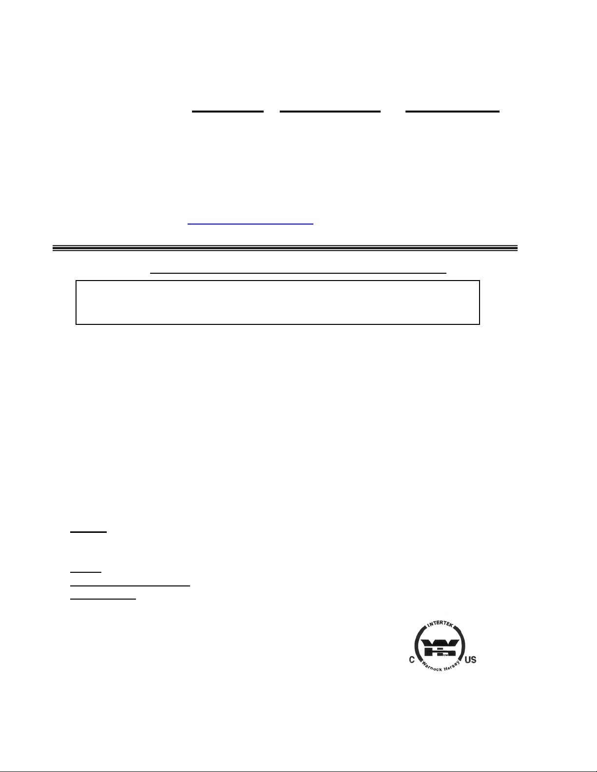
1. Masonry Flue: If you are considering a masonry flue (see Figure 1), you should
contact your local building officials for the proper procedures required in the
construction. We recommend that you consult with and have your flue built by a
licensed, bonded contractor.
Most masonry flues are placed against the outside wall and extend up the side of
the house. A flue thimble is then inserted through the wall making the connection
with the vertical flue and the stove flue pipe. Extreme caution should be
exercised when drilling through the wall. You must maintain proper clearances
between the connecting liner and any combustible wall. We do recommend that
you have a flue clean out door at least 2’ (two feet) below the flue thimble for
easy access and cleaning. This door should be made as air tight as possible. It is
the customer’s responsibility to be sure the chimney (or flue system) is in a safe
operating condition. The manufacturer will not be held responsible for an
accident attributed to a unit connected to a faulty chimney or flue system.
2. Premanufactured Flue System: In the past few years, premanufactured flue
systems have become very popular. This type system is fairly easy to install and
when installed correctly, it is a very safe. There are many premanufactured flue
systems on the market from which to choose. In making your choice, be sure the
system has a recognized label of approval such as U.L., B.O.C.A. or I.C.B.O.
Any of these labels will ensure the flue system is constructed of the proper
materials and meets the required safety standards. Your local dealer will
normally handle an approved, high-quality flue system.
NOTE: Be sure to use “HT” Pipe.
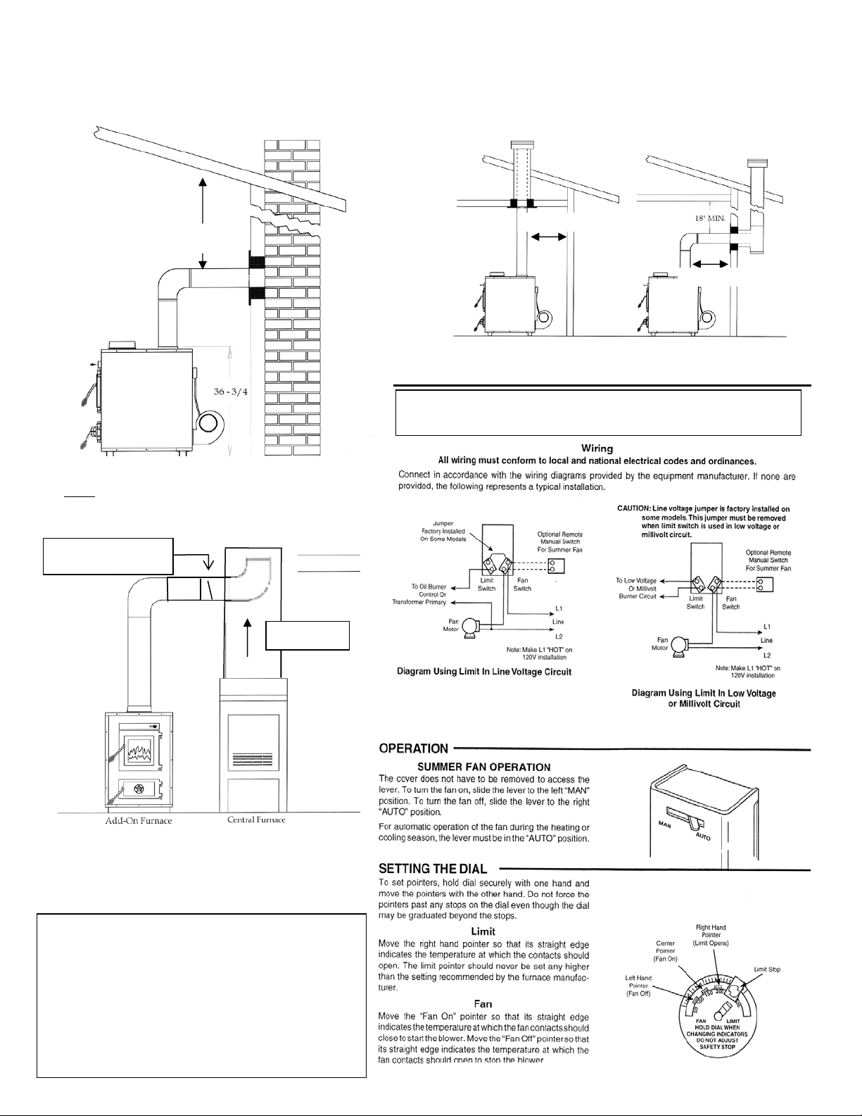
There are two very popular methods of installing a premanufactured flue system.
The first, which is the least expensive, is up through the ceiling and out the roof
(see Figure 2). This is the most direct route and creates more draft because less
pipe is normally used. Single wall pipe (24 gauge) is used up to the ceiling, with
triple walled pipe through the attic and out the roof.
The second
method of installation is to go through the wall and up the outside of
your home or structure (see Figure 2). This method is more expensive because it
requires more pipe, and once outside the home insulated or triple wall pipe is
required. Extreme care should be used in any installation, and the manufacturers’
instructions should always be followed. If you choose this type installation, a
qualified contractor or bonded chimney sweep should install this system. It is the
customers’ responsibility to be sure the flue system is in a safe operating
condition.
*IMPROPER INSTALLATION: The manufacturer will not be held responsible for damage
caused by the malfunction of a stove due to improper venting or installation. Call
800-245-6489 and/or consult a
4
rofessional installer if you have any questions.
Installation Diagrams and Thermostat Wiring
A
p
This appliance requires a masonry or pre-manufactured chimney listed to UL103HT, sized
correctly.
18” Min.
18” Min.
18” Min.
Figure 1 – Installation into a Masonry Flue
NOTE: 13” required from back of unit to a combustible.
16” required from sides of unit to a combustible.
See Floor and Wall Protection sections and data label
Recommended position
of Backflow Damper
on stove for all clearances.
ir Flow
Figure 3 – Hot air outlet hook-up to ductwork.
NOTE: Be sure to connect to ductwork from
furnace’s 8” hot air outlet only (see Section V)
.
To prevent air flow from central furnace
being directed back into the Add-on furnace:
A Backflow Damper is required in the 8” hot air
outlet pipe that connects from the Add-On
Furnace to the Central Furnace (see Figure 3).
We also recommend a 8” (eight inch), 90
5
lenum or ductwork.
degree elbow (a slightly larger hole will be
required for installation) inside central furnace
Figure 2 – Installation into a HT Pipe Flue System.
– Through the Roof RIGHT – Through the Wall
LEFT
IMPORTANT NOTE: Do NOT connect this furnace to
an external thermostat.
Figure 4 – Blower thermostat wiring diagram.

SECTION II: FLOOR AND WALL PROTECTION
A. Floor Protection
There is no protection required if your floor is constructed of a
noncombustible material such as concrete. If your floor is constructed of a
combustible material such as hardwood, carpet or linoleum some type of
floor protection will be required. When selecting the required floor
protection it is important that you install a U.L. approved board. The
approved floor protection should be placed underneath the furnace, and
should be large enough to provide a minimum of 8” (8 inches) behind the
unit, 8”(8 inches) on both sides, and 16” (16 inches) at the front door(s)
location. It should also be placed underneath the chimney connector and
extend at least 2” (2 inches) on either side of the chimney connector.
B. Wall Protection
Your furnace can be placed as close as 16” (16 inches) from a
combustible wall (such as paneling, wallpaper or drywall) to the side of the
unit; from the back of the unit, 13” (13 inches) is required to a combustible.
The single-wall pipe would need to remain at least 18” (18 inches) from
combustible surfaces.
In corner installations, the unit should be placed so that the stove is at
least 12” (12 inches) from any combustibles, and the single-wall pipe
should be at least 23” (23 inches) from any combustibles in a corner
installation.
Wall protection will be required if you need to place you furnace closer
than the allowed measurements stated above, and this can be
accomplished by adding a protective board to the wall. The board can be
mounted to the wall leaving a one-inch air space between the wall and the
board. This can be done by using metal spacers, and should allow you to
place your unit so that the sides of the unit are at least 12” (12 inches)
from the protective board – be sure to check and follow the board
manufacturer’s instructions and any local codes.
SECTION III: FREESTANDING PLACEMENT AND HOOK-UP
Once you have completed your flue system and installed the floor
protection, you are now ready to place the unit. All of our stoves are well
constructed, making them very heavy. We recommend using a handcart
for moving the unit; the door and firebrick can be removed to make the
unit slightly lighter (first make a diagram of the firebrick layout for later
reference). Never attempt to handle this product alone.
After the unit is in place the flue collar, spring handles and any optional
equipment can be added.
6
 Loading...