

Page 1
Gigabit Managed Smart Switch
with Wireless Controller
Business Solutions
EWS Switch Series
1
Page 2

IMPORTANT
To install this device please refer to the
Quick Installation Guide included in the
product packaging.
2
Page 3

Table of Content
s
Product Overview ...............................................................................................................................................7
Introduction ............................................................................................................................................ 8
Key Features ........................................................................................................................................ 9
System Requirements ....................................................................................................................... 10
Package Contents .............................................................................................................................. 10
Technical Specifications ..................................................................................................................... 11
Getting Started ................................................................................................................................................. 14
Installing the Switch .............................................................................................................................. 15
Management Interface ..................................................................................................................... 15
Connecting the Switch to a Network ................................................................................................ 16
Software Features .......................................................................................................................................... 18
Using the Switch .................................................................................................................................... 19
Wireless Controller Features ................................................................................................................. 20
Managing EWS Access Points ............................................................................................................ 20
Device Management ......................................................................................................................... 22
Summary ....................................................................................................................................... 22
Access Points ................................................................................................................................. 24
Access Point Settings ..................................................................................................................... 29
AP Groups...................................................................................................................................... 42
Access Control ............................................................................................................................... 44
Wireless Services ........................................................................................................................... 46
Monitor ............................................................................................................................................. 47
Active Clients ................................................................................................................................. 47
Rogue AP Detection ...................................................................................................................... 49
System Log .................................................................................................................................... 51
Email Alert ..................................................................................................................................... 56
Visualization ...................................................................................................................................... 60
Topology View ............................................................................................................................... 60
Map View ...................................................................................................................................... 63
Floor View ..................................................................................................................................... 65
Statistics ............................................................................................................................................ 70
Access Points ................................................................................................................................. 70
3
Page 4

Wireless Clients ............................................................................................................................. 71
Real Time Throughput ................................................................................................................... 72
Hotspot Services ............................................................................................................................... 73
Captive Portal ................................................................................................................................ 73
Guest Account ............................................................................................................................... 75
Maintenance ..................................................................................................................................... 76
Schedule Tasks .............................................................................................................................. 76
Troubleshooting ............................................................................................................................ 77
Bulk Upgrade ................................................................................................................................. 78
One-Click Update .......................................................................................................................... 79
SSL Certificate ................................................................................................................................ 82
Check Codes .................................................................................................................................. 84
Migration to ezMaster .................................................................................................................. 85
Ethernet Switch Features ...................................................................................................................... 86
System ............................................................................................................................................... 86
Summary ....................................................................................................................................... 86
IP Settings ...................................................................................................................................... 87
System Time .................................................................................................................................. 90
Port Settings .................................................................................................................................. 92
PoE ................................................................................................................................................ 94
EEE ................................................................................................................................................. 97
L2 Feature.......................................................................................................................................... 98
Link Aggregation ............................................................................................................................ 98
STP ............................................................................................................................................... 105
MAC Address Table ..................................................................................................................... 116
LLDP ............................................................................................................................................. 118
IGMP Snooping ........................................................................................................................... 122
MLD Snooping ............................................................................................................................. 128
Jumbo Frame ............................................................................................................................... 131
VLAN ................................................................................................................................................ 132
802.1Q ......................................................................................................................................... 133
PVID ............................................................................................................................................. 134
Management VLAN ..................................................................................................................... 136
Voice VLAN .................................................................................................................................. 137
4
Page 5

Management ................................................................................................................................... 140
System Information ..................................................................................................................... 140
User Management ...................................................................................................................... 141
Dual Image .................................................................................................................................. 142
SNMP ........................................................................................................................................... 143
ACL .................................................................................................................................................. 152
MAC ACL ...................................................................................................................................... 153
MAC ACE ..................................................................................................................................... 154
IPv4 ACL ....................................................................................................................................... 156
IPv4 ACE ...................................................................................................................................... 157
IPv6 ACL ....................................................................................................................................... 159
IPv6 ACE ...................................................................................................................................... 160
ACL Binding ................................................................................................................................. 162
QoS .................................................................................................................................................. 163
Global Settings ............................................................................................................................ 164
CoS Mapping ............................................................................................................................... 165
DSCP Mapping ............................................................................................................................. 166
Port Settings ................................................................................................................................ 167
Storm Control .............................................................................................................................. 169
Security ........................................................................................................................................... 171
802.1x .......................................................................................................................................... 171
RADIUS Server ............................................................................................................................. 175
Access .......................................................................................................................................... 176
Port Security ................................................................................................................................ 180
Port Isolation ............................................................................................................................... 181
DoS .............................................................................................................................................. 182
Monitoring ...................................................................................................................................... 184
Port Statistics............................................................................................................................... 184
RMON .......................................................................................................................................... 185
Log ............................................................................................................................................... 190
Diagnostics ...................................................................................................................................... 195
Cable Diagnostics ........................................................................................................................ 195
Ping Test ...................................................................................................................................... 196
IPv6 Ping Test .............................................................................................................................. 197
5
Page 6

Trace Route ................................................................................................................................. 198
Maintenance ................................................................................................................................... 199
Configuration Manager ............................................................................................................... 199
Firmware Upgrade ...................................................................................................................... 200
Appendix .......................................................................................................................................................... 201
Appendix A - Federal Communication Commission Interference Statement ..................................... 202
Appendix B - IC Interference Statement ............................................................................................. 203
Appendix C - CE Interference Statement ............................................................................................ 204
6
Page 7
Chapter 1
Product Overview
7
Page 8

Introduction
The EnGenius EWS Series of Wireless Management Switches is an affordable centralized wired/wireless
management system developed specifically for entry-level small-to-medium businesses. This powerful
device can be easily deployed and operated by non-tech experts and installed effortless and quickly. Any
organization with limited IT engineer and budget can create a stable and secure wireless network in no
time. The system integrates seamlessly with existing routers, switches, firewalls, authentication servers
and other network devices, and can be placed within any network, configured to act as a both a Wireless
Controller as well as a Layer 2 Gigabit switch, providing robust and centralized management of the whole
network through one powerful system. With no additional costs or license purchasing necessary,
network administrators can manage and monitor both wired and wireless nodes through a single web
interface.
The system can automatically discover any supported EnGenius EWS Series Access Points connected to
the network with a simple click of a mouse, self-configure and become instantly manageable. Simply log
into the device via any standard web browser and assign APs into cluster groups. Wireless radio, wireless
security and other wireless related configurations can all be easily applied to multiple APs simultaneously,
eliminating the time consuming process of configuring each and every Wireless Access Points
individually.
The user friendly GUI provides instant access to a variety of client and network information including
Managed AP List, Auto Discovered AP List, Cluster Grouping List, and Client List with complete MAC/IP
Address, Incoming/Outgoing Traffic, Wireless Output Power and other relevant information. Statistics of
AP and client traffics are automatically generated into easy-to-understand graphs, providing a visual
representation of the network traffic.
Not to forget the Topology View feature that allows administrators to quickly see the whole
wired/wireless network topology at real-time for easier planning, troubleshooting and monitoring, as
well as Floor Plan View and Map View which allows for quickly locating deployed APs, a helpful feature
for large scale AP deployment and multi-site management. There's also an Intelligent Diagnostics feature
for administrators to check the status of Wireless APs and provide easy troubleshooting for offline units
and even capable of rebooting APs remotely.
8
Page 9

Key Features
> 10/100/1000 Mbps Gigabit Ethernet Ports
> Dedicated SFP slots for longer connectivity via fiber uplinks and for uplink redundancy and
failover
> IGMP and MLD snooping provides advanced multicast filtering
> IEEE802.3ad Link Aggregation
> STP/RSTP/MSTP
> Access Control List/ Port Security
> IEEE802.1X and RADIUS Authentication
> RMON
> SNMP v1/v2c/v3
> Voice VLAN for fast and reliable deployment of VoIP
> Energy Efficient Ethernet (IEEE802.3az) support for better energy saving when more
EEE-compliant end devices are available in the market
> Advanced QoS with IPv4/IPv6 ingress traffic filtering (ACLs) and prioritization
> Easy to manage via Web-Based Management GUI for switch deployment
> Standard-based technology, ensuring interoperability with any standard-based devices in the
existing network
> Dual firmware images, improving reliability and uptime for your network
9
Page 10

System Requirements
The following are the minimum system requirements in order configure the device:
> Computer with an Ethernet interface or wireless network capability
> Windows OS (XP, Vista, 7, 8), Mac OS, or Linux-based operating systems
> Web-Browsing Application (i.e. Internet Explorer, Firefox, Chrome, Safari, or another similar
browser application)
Package Contents
The package contains the following items (all items must be in package to issue a refund):
EWS1200D-10T, EWS2910P
> EnGenius Switch
> Power Adapter
> Wall-mount Kit
> Quick Installation Guide
EWS1200-28T/52T, EWS5912FP, EWS7928P/FP, EWS7952FP
> EnGenius Switch
> Power Cord
> Rack-mount Kit
> Quick Installation Guide
10
Page 11

Technical Specifications
EWS1200D-10T
EWS1200-28T
EWS1200-52T
10/100/1000Mbps Ports
8
24
48
100/1000Mbps SFP Slots
2 4 4
RJ45 Console Ports
- 1 1
Forwarding Mode
Store-and-Forward
SDRAM
256 MB
256 MB
256 MB
Flash Memory
32 MB
32 MB
32 MB
Packet Buffer Memory
512 KB
512 KB
1.5 MB
EWS2910P
EWS5912FP
EWS7928P
EWS7928FP
EWS7952FP
10/100/1000Mbps Ports
8
10
24
24
48
100/1000Mbps SFP Slots
2 2 4 4 4
RJ45 Console Ports
- 1 1 1 1
PoE Standard
IEEE 802.3 af
IEEE 802.3 af/at
PoE Capable Ports
Port 1-8
Port 1-8
Port 1-24
Port 1-24
Port 1-48
Total PoE Power Budget
55W
130W
185W
370W
740W
Forwarding Mode
Store-and-Forward
SDRAM
256 MB
256 MB
256 MB
256 MB
256 MB
Flash Memory
32 MB
32 MB
32 MB
32 MB
32 MB
Packet Buffer Memory
512 KB
512 KB
512 KB
512 KB
1.5 MB
General
11
Page 12

Software Features
Wireless Management Features
Access Point Auto Discovery and Provisioning
Access Point Auto IP Assignment
Access Point Group Management
Visual Topology View
Floor Plan View
Map View
Access Point Status Monitoring
Wireless Client Monitoring
Wireless Traffic & Usage Statistics
Real-time Throughput Monitoring
Bulk Firmware Upgrade Capability
Remote Access Point Rebooting
Fast Roaming
Band Steering
Traffic Shaping
Intelligent Diagnostics
Access Point Device Name Editing
Access Point Radio Settings
RSSI Threshold
Access Point Client Limiting
Wireless Security (WEP, WPA/WPA2 Enterprise,
WPA/WPA2 PSK)
VLANs for Access Point- Multiple SSIDs
Guest Network
Secure Control Messaging (SSL Certificate)
Local MAC Address Database
Remote MAC Address Database (RADIUS)
Configuration Import / Export
L2 Features
802.3ad Link Aggregation
- Maximum of 8 groups/8 ports per group
Port Mirroring
- One-to-One
- Many-to-One
Spanning Tree Protocol
- 802.1D Spanning Tree Protocol (STP)
- 802.1w Rapid Spanning Tree Protocol (RSTP)
- 802.1s Multiple Spanning Tree Protocol (MSTP)
MAC Address Table
- 8K entries
Static MAC Address
- 256 entries
802.1ab Link Layer Discovery Protocol
IGMP Snooping
- IGMP v1/v2/v3 Snooping
- Supports 256 IGMP groups
- IGMP per VLAN
- IGMP Snooping Querier
- IGMP Snooping Fast Leave
MLD Snooping
- MDL Snooping v1/v2
- Supports 256 MLD groups
- IGMP per VLAN
Jumbo Frame
- Up to 9216 bytes
802.3x Flow Control
802.3az Energy Efficient Ethernet
VLAN
802.1Q support
VLAN Group
- Max 4094 static VLAN groups
Voice VLAN
QoS
802.1p Quality of Service
- 8 queues per port
Queue Handling
- Strict
- Weighted Round Robin (WRR)
QoS based on:
- 802.1p Priority
- DSCP
Bandwidth Control
- Port-based (Ingress/Egress, 64 Kbps~1000
Mbps)
Broadcast/Unknown Multicast/ Unknown Unicast
Storm Control
Access Control List (ACL)
Layer 2/3
- Support maximum 32 entries (ACL)
- Support maximum 256 entries (ACE)
ACL based on:
- MAC address
- VLAN ID
12
Page 13

- 802.1p priority
- Ethertype
- IP address
- Protocol type
- DSCP
Security
802.1X
- Guest VLAN
- Port-based Access Control
Supports RADIUS Authentication
Port Security
- up to 256 MAC Addresses per port
Port Isolation
DoS Attack Prevention
BPDU Attack Prevention
Monitoring
Port Statistics
System Log
RMON
Management
Web Graphical User Interface (GUI)
Command Line Interface (CLI)
BootP/DHCP Client/DHCPv6 Client
SSH Server
Telnet Server
TFTP Client
HTTPS
SNMP
- Supports v1/v2c/v3
SNMP Trap
SNTP
Configuration restore/backup
Dual Images
Diagnostic
Cable Diagnostic
Ping Test
Trace Route
MIB/RFC Standards
RFC1213
RFC1493
RFC1757
RFC2674
RFC 2863
Environment Specifications
Operating Temperature
0 to 40°C (EWS1200D-10T, EWS2910P)
0 to 50°C (EWS1200-28T/52T, EWS5912FP,
EWS7228P/FP, EWS7952FP)
Storage Temperature
-40°C to 70°C
Humidity (Non-condensing)
5% - 95%
Physical Specifications
Dimensions (W x D x H)
EWS1200D-10T, EWS2910P: 240x105x27mm
EWS5912FP: 330x230x44mm
EWS1200-28T/52T, EWS7228P: 440x260x44mm
EWS7928FP: 440x310x44mm
EWS7952FP: 440x410x44mm
13
Page 14

Chapter 2
Getting Started
14
Page 15

Installing the Switch
This section will guide you through the installation process.
Management Interface
The Switch features an embedded Web interface for the monitoring and management of your device.
Management Interface Default Values
IP Address: 192.168.0.239
Username: admin
Password: password
15
Page 16

Connecting the Switch to a Network
Discovery in a Network with a DHCP server
Use the procedure below to setup the Switch within a network that uses DHCP.
1. Connect the supplied Power Cord to the Switch and plug the other end into an electrical outlet.
Verify the power LED indicator is lit on the Switch.
2. Wait for the Switch to complete booting up. It might take a minute for the Switch to completely boot
up.
3. Connect one end of a Category 5/6 Ethernet cable into the Gigabit (10/100/1000Mpbs) Ethernet
port on the Switch front panel and the other end to the Ethernet port on the computer. Verify that
the LED on the Ethernet ports of the Switch are Green.
4. Once your computer is on, ensure that your TCP/IP is set to On or Enabled. Open Network
Connections and then click Local Area Connection. Select Internet Protocol Version 4 (TCP/IPv4). If
your computer is already on a network, ensure that you have set it to a Static IP Address on the
Interface (Example: 192.168.0.10 and the Subnet mask address as 255.255.255.0).
5. Open a web browser on your computer. In the address bar of the web browser, enter 192.168.0.239
and press Enter.
6. A login screen will appear. By default, the username is admin and the password is password. Enter
the current password of the Switch and then click Login. To make access to the web-based
management interface more secure, it's highly recommended that you change the password to
something more unique.
7. Click IP Settings under the System tab and select IPv4 or IPv6.
8. Click DHCP under Auto-Configuration.
9. Click Apply to save the settings.
10. Connect the Switch to your network (DHCP enabled).
11. On the DHCP server, find and write down the IP address allocated to the device. Use this IP address
to access the management interface.
16
Page 17

Discovery in a Network with a DHCP server
This section describes how to set up the Switch in a network without a DHCP server. If your network has
no DHCP service, you must assign a static IP address to your Switch in order to log in to the web-based
management interface.
1. Connect the supplied Power Cord to the Switch and plug the other end into an electrical outlet.
Verify the Power LED indicator is lit on the Switch.
2. Wait for the Switch to complete booting up. It might take a minute or so for the Switch to completely
boot up.
3. Connect one end of a Category 5/6 Ethernet cable into the Gigabit (10/100/1000Mbps) Ethernet
port on the Switch front panel and the other end to Ethernet port on the computer. Verify that the
LED on Ethernet ports of the Switch are Green.
4. Once your computer is on, ensure that your TCP/IP is set to On or Enabled. Open Network
Connections and then click Local Area Connection. Select Internet Protocol Version 4 (TCP/IPv4).
5. If your computer is already on a network, ensure that you have set it to a Static IP Address on the
Interface (Example: 192.168.0.239 and the Subnet mask address as 255.255.255.0).
6. Open a web browser on your computer. In the address bar of the web browser, enter 192.168.0.239
and press Enter.
7. A login screen will appear. By default, the username is admin and the password is password. Enter
the current password of the Switch and then click Login. To make access to the web-based
management interface more secure, it's highly recommended that you change the password to
something more unique.
8. Click IP Settings under the System menu and select Static IP to configure the IP settings of the
management interface.
9. Enter the IP address, Subnet mask, and Gateway.
10. Click Apply to update the system.
17
Page 18
Chapter 3
Software Features
18
Page 19
Using the Switch
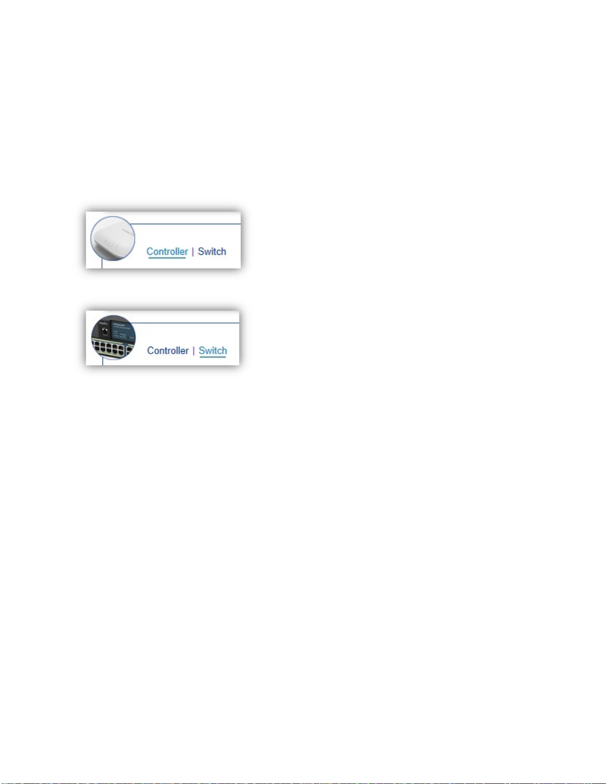
Besides the functions of a Wireless Controller, the EWS Wireless Management Switch also possesses
functions of a full-featured Layer 2 Ethernet Switch. Use the Controller / Switch tab on the upper left
corner of the user interface to toggle between the Wireless Controller or Layer 2 Switch functions.
19
Page 20
Wireless Controller Features
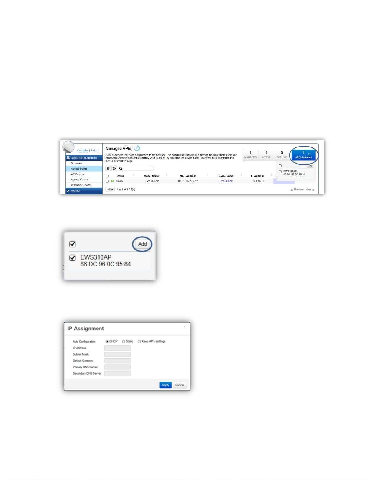
Managing EWS Access Points
1. Access Points in the network will be automatically discovered by the EWS and will be listed under
the AP(s) Detected list in the Access Point menu.
2. Select the Access Point(s) you wish to manage and click Add.
3. You will be prompted to assign the IP Address under the IP Assignment screen.
20
Page 21

Auto-Configuration
DHCP: You can choose to auto assign IP address if there is a
DHCP server in the network.
Static: If you wish to manually assign the IP address, choose
Static. Enter the IP address you wish to assign to the AP and fill
in the subnet mask, default gateway and DNS server address.
Keep AP’s Settings: Select this option for the AP to use its
current network settings.
IP Address
Enter the IP address for the Access Point.
Subnet Mask
Enter the subnet mask for the Access Point.
Default Gateway
Enter the default gateway for the Access Point.
Primary DNS Server
Enter the primary DNS server name.
Secondary DNS Server
Enter the secondary DNS server name (if necessary).
4. Click Apply and the Access Point(s) you’ve configured will be moved to the Managed list. Note that
the status of the AP will change from Connecting to Provisioning to Online. Once the status turns
Online, your Access Point(s) have been successfully added to the Managed list.
Note: If the status shows Incompatible Version, please check and make sure that the firmware of the
Access Point and Switch are compatible.
21
Page 22
Device Management
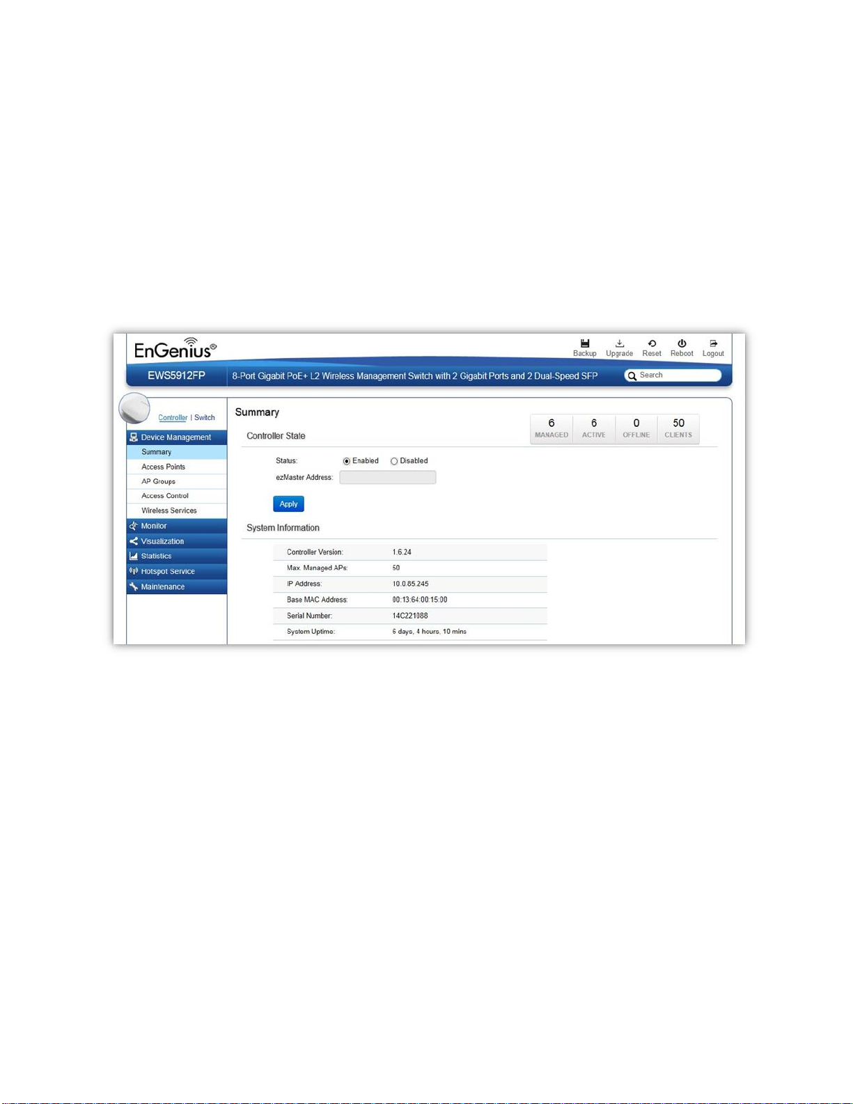
Summary
The Summary page shows general system information for the EWS Switch including the Controller Status,
the software version, the maximum number of APs the system can manage, MAC Address, IP Address,
serial number, and system uptime for the system.
22
Page 23

Managed
This shows the number of APs currently managed by the EWS Switch.
Active
This shows the number of managed APs that currently have an active connection with the
EWS Switch.
Offline
This shows the number of managed APs that currently do not have an active connection with
the EWS Switch.
Clients
This shows the total number of wireless clients currently connected to all the managed APs.
Dashboard
The Dashboard on the upper right corner of the GUI shows the current status of EWS APs that has been
managed by the EWS Switch.
Controller State
Status: Select whether to Enable or Disable the Controller feature on the Switch.
ezMaster Address: If you have an ezMaster server running and wants to have ezMaster manage this
EWS Switch directly, enter the IP Address/domain name of the ezMaster server.
Click Apply to save the changes to the system.
System Information
Controller Version: This is the software version of the device.
Max. Managed APs: The maximum number of APs the device is able to manage.
IP Address: Displays the IP address of the device.
Base MAC Address: Universally assigned network address.
Serial Number: Displays the serial number of the device.
System Uptime: Displays the number of days, hours, and minutes since the last system restart.
23
Page 24
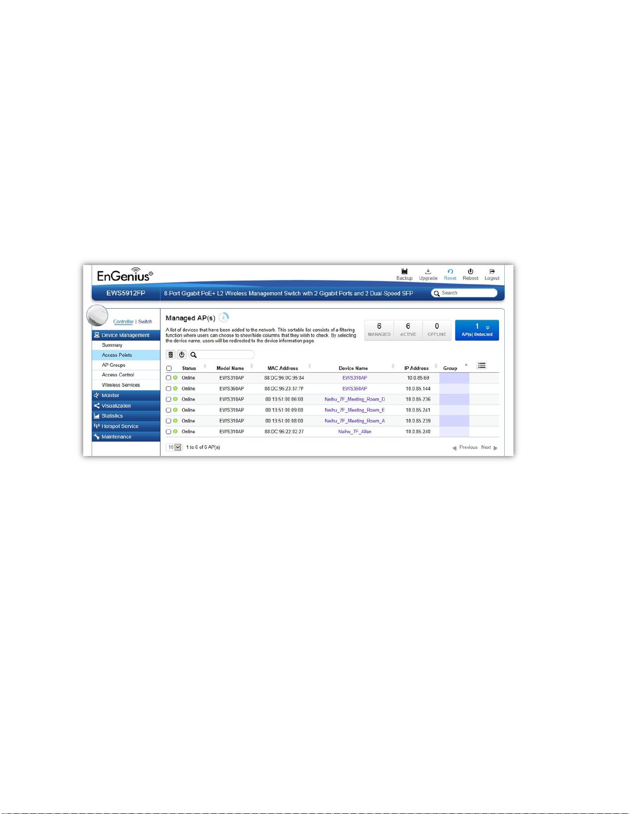
Access Points
This page displays the status of all EWS Access Points that your Controller is currently managing as well
as all the EWS Access Points in the network that the Controller has discovered. Use this page to add EWS
Access Points to your EWS Controller Access Point list.
The EWS Switch is able to manage supported EWS Series Access Points. For the discovery procedure to
succeed, the EWS Switch and the EWS Access Point must be connected in the same network. The EWS
Switch can discover supported EWS Access Points with any IP address and Subnet settings.
Managing Access Points
EWS Access Points can either be configured individually or configured as a group.
To manage an Access Point individually, click on the Device Name field of the Access Point you wish to
configure and you will be directed to a screen where you can configure settings for the Access Point.
To manage Access Points as a group, go to Device Management > AP Clusters to create an AP group and
add members into the group. Click on the Group field of the AP you wish to configure and you will be
directed to a screen where you can configure settings for the AP Group.
Group settings can be overridden by individual AP settings. For example, if you want to set the transmit
power to a lower setting for only a few specific APs, leave the Transmit Power at Auto in the Wireless
24
Page 25

Managed
This shows the number of APs in the managed AP database that are configured
with the EWS Switch.
Active
This shows the number of managed APs that currently have an active connection
with the EWS Switch.
Offline
This shows the number of managed APs that currently do not have an active
connection with the EWS Switch.
Radio Settings of the AP Group, then click on the Device Name field of the Access Point (which is already
in a group) you wish to configure and you will be directed to a screen where you can configure override
settings for the selected Access Point.
Refresh Countdown Timer
This is the time left before the page auto-refreshes. The countdown is from 15 seconds.
Dashboard
The Dashboard shows the current status of all the EWS APs that has been managed by the EWS Switch.
AP(s) Detected List
Reveals a list of all APs in the network that the EWS Switch automatically discovers. Mouse over the
discovered Access Point to show general information such as the MAC address, IP address, model name
and firmware version.
25
Page 26

Status
Explanation
Online
AP is connected and managed by EWS Switch.
Provisioning
AP is currently in the process of connecting to the EWS Switch.
Applying Change
AP is currently applying system changes.
Connecting
AP is currently connecting to EWS Switch.
Offline
AP is currently offline.
Remove AP
The Remove button removes selected Access Point(s) from list. Access Points removed will be
automatically set to standalone mode with all settings restored to their factory default settings.
Reboot AP
The Reboot button will reboot the selected Access Point(s).
Search Bar
Use the Search Bar to search for Access Points managed by the EWS Switch using the following criteria:
Status, model name, MAC Address, Device name, IP address, Firmware Version, Cluster.
Status
This indicates the current status of the managed Access Point.
26
Page 27

Resetting
AP is resetting.
Firmware
Upgrading
AP is currently undergoing firmware upgrade process.
Invalid IP
The subnet of managed AP’s IP address is not the same as the EWS Switch. Please
remove AP and reconfigure AP to the correct setting.
Incompatible
Version
AP firmware is not compatible with EWS Switch.
Checking
Certificate
EWS Switch is checking the SSL Certificate of AP.
Model Name
Shows the model name of the managed Access Point.
MAC Address
Shows the MAC address of the managed Access Point.
Device Name
Displays the device name of the managed Access Point.
When the AP is not a cluster member, click on this field and you’ll be redirected to the configuration
page where you can edit settings such as device name, IP Address, Wireless Radio settings.
When the AP is a cluster member, click on this field to configure settings for individual Access Points
by overriding the cluster settings.
IP Address
Shows the IP address of the managed Access Point.
27
Page 28

Firmware Version
Shows the firmware version of the managed Access Point.
Last Update
Display the time the Access Point was last detected and the information was last updated.
Group
Displays the AP Group the Access Point is currently assigned to. Click on this field and you'll be redirected
to the group configuration page.
Column Filter
Shows or hides fields in the Access Point list.
28
Page 29
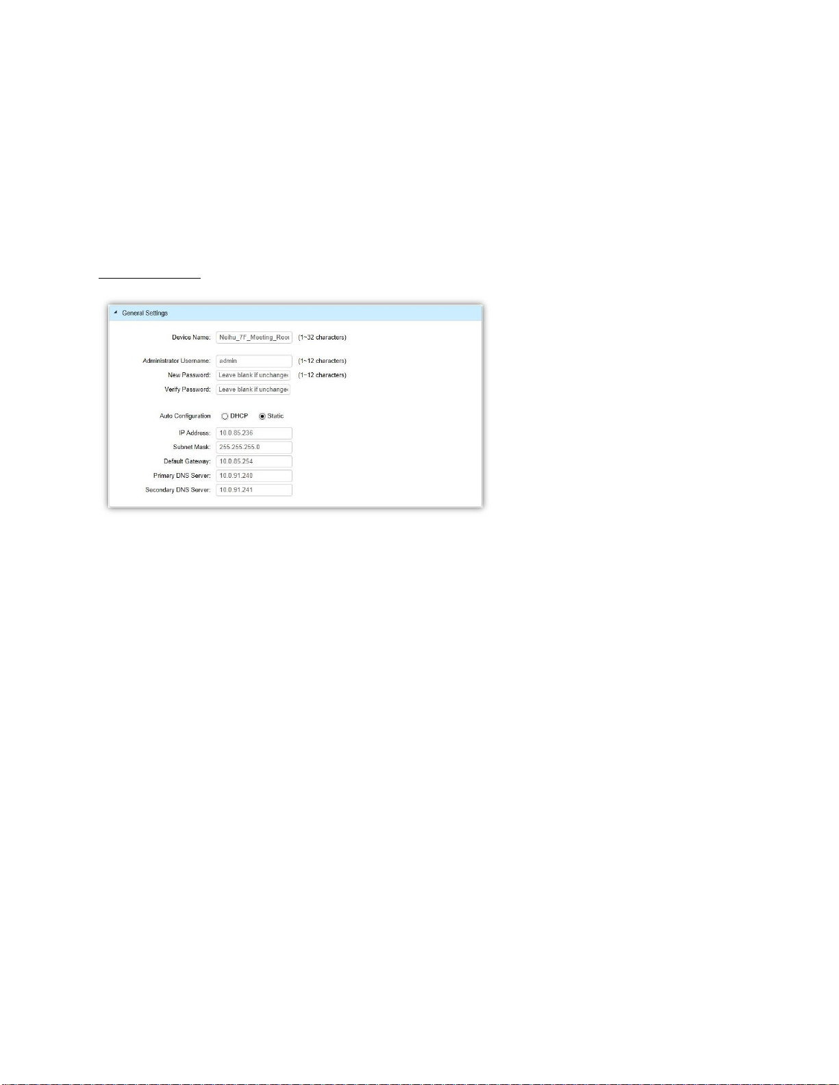
Access Point Settings
On this page, you can edit the AP's name and password, manually assign an IP address, or change the
channel selection, transmit power and other wireless settings of a managed Access Point.
General Settings
Device Name: The device name of the Access Point. Users can enter a custom name for the Access Point
if they wish.
Administrator Username: Displays the current administrator login username for the Access Point. Enter
a new Administrator username for the Access Point if you wish to change the username. The default
username is: admin.
New Password: Enter a new password of between 1~12 alphanumeric characters.
Verify Password: Enter the password again for confirmation.
Auto Configuration: Select whether the device IP address will use the static IP address specified in the IP
Address field or be obtained automatically when the device connects to a DHCP server.
IP Address: Enter the IP address for the Access Point.
Subnet Mask: Enter the Subnet Mask for the Access Point.
Default Gateway: Enter the default Gateway for the Access Point.
Primary/Secondary DNS Server: Enter the Primary/Secondary DNS server name.
29
Page 30
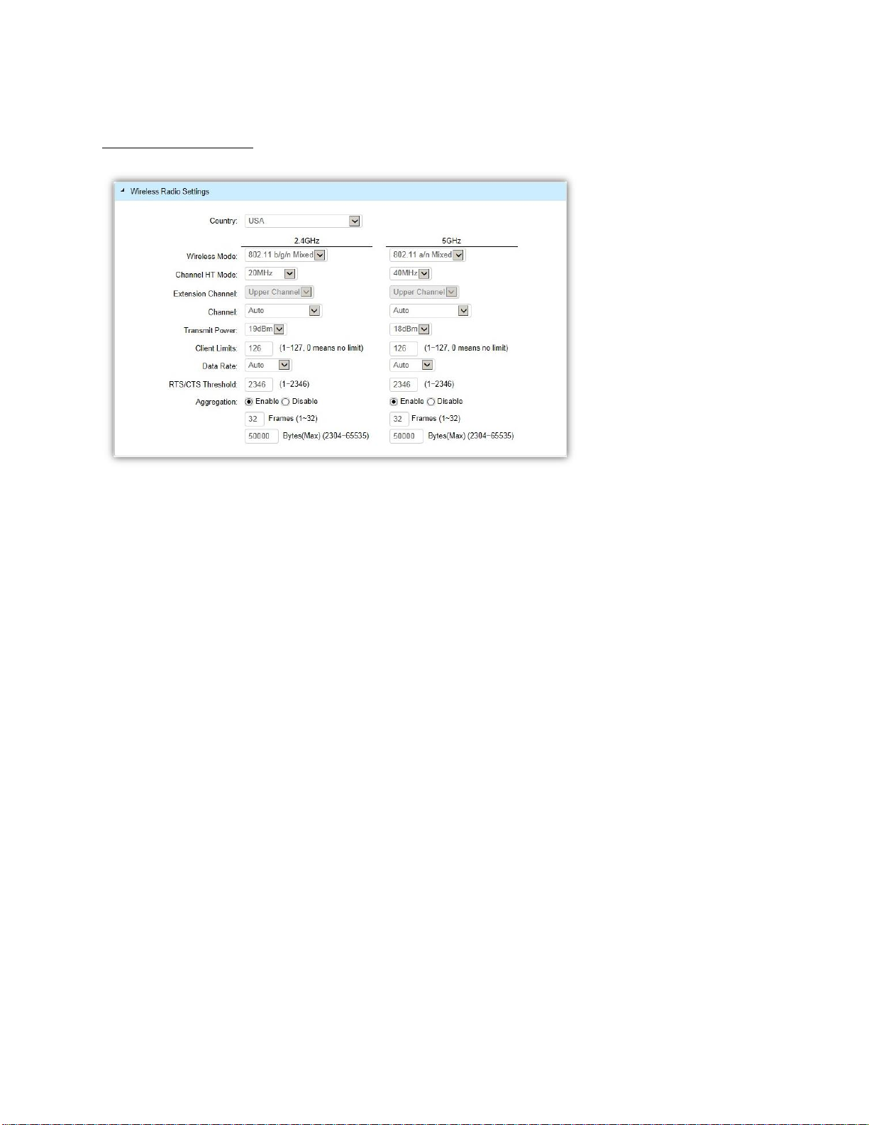
Wireless Radio Settings
Country: Select a Country/Region to conform to local regulations. Different regions have different rules
that govern which channels can be used for wireless communications.
Wireless Mode: Select from the drop-down menu to set the wireless mode for the Access Point. For
2.4GHz, the available options are 802.11b/g/n mixed, 802.11b, 802.11b/g mixed, 802.11g, and 802.11n.
For 5GHz, the available options are 802.11a/n mixed, 802.11a, and 802.11n.
Channel HT Mode: Use the drop-down menu to select the Channel HT as 20MHz, 20/40MHz or 40MHz.
A wider channel improves the performance, but some legacy devices operate only on either 20MHz or
40 MHz. This option is only available for 802.11n modes.
Extension Channel: Use the drop-down menu to set the Extension Channel as Upper or Lower channel.
An extension channel is a secondary channel used to bond with the primary channel to increase this
range to 40MHz allowing for greater bandwidth. This option is only available when Wireless Mode is
802.11n and Channel HT Mode is 20/40MHz or 40MHz.
Channel: Use the drop-down menu to select the wireless channel the radio will operate on. Optimizing
channel assignments reduces channel interference and channel utilization for the network, thereby
improving overall network performance and increasing the network's client capacity. The list of available
channels that can be assigned to radios is determined based on which country the Access Points are
deployed in.
30
Page 31

Transmit Power: Allows you to manually set the transmit power on 2.4GHz or 5GHz radios. Increasing
the power improves performance, but if two or more Access Points are operating in the same area on
the same channel, it may cause interference.
Client Limits: Specify the maximum number of wireless clients that can associate with the radio. Enter a
range from 1 to 127, or fill in 0 for an unlimited client limit.
Data Rate: Use the drop-down list to set the available transmit data rates permitted for wireless clients.
The data rate affects the throughput of the access point. The lower the data rate, the lower the
throughput, but the longer transmission distance.
RTS/CTS Threshold: Enter a Request to Send (RTS) Threshold value between 1~2346. Use RTS/CTS to
reduce data collisions on the wireless network if you have wireless clients that are associated with the
same Access Point. Changing the RTS threshold can help control traffic flow through the Access Point. If
you specify a lower threshold value, RTS packets will be sent more frequently. This will consume more
bandwidth and reduce the throughput of the Access Point. Sending out more RTS packets can help the
network recover from interference or collisions which might occur on a busy network or on a network
experiencing electromagnetic interference.
Aggregation: Select whether to enable or disable Aggregation for the Access Point. This function merges
data packets into one packet, reducing the number of packets. This also increases the packet sizes, so
please keep this in mind. Aggregation is useful for increasing bandwidth throughput in environments
that are prone to high error rates. This mode is only available for 802.11n modes. Fill in the frame rate
limit you wish to use. The range is from 1~32. Next, fill in the max byte limit. The range is from
2304~65535.
WLAN Settings - 2.4GHz/5GHz
Under the WLAN Settings, you can create and manage SSID configurations and profiles for the Access
Points to fit your needs. An SSID is basically the name of the wireless network to which a wireless client
can connect to. Multiple SSIDs allow administrators to use a single physical network to support multiple
applications with different configuration requirements. Up to 8 SSIDs are available per radio. Click on the
SSID you wish to make changes to and you'll be directed to the SSID Configuration page.
31
Page 32

ID
The ID displays the SSID profile identifier.
Status
This displays whether the current SSID profile is enabled or disabled.
SSID
Displays the SSID name as it appears to the wireless clients in the
network.
Security
Displays the security mode the SSID uses.
Encryption
Displays the data encryption type the SSID uses.
Hidden SSID
Displays whether the hidden SSID is enabled or disabled.
Client Isolation
Displays whether Client Isolation feature is enabled or disabled.
L2 Isolation
Displays whether L2 Isolation feature is enabled or disabled.
VLAN Isolation
Displays whether VLAN Isolation feature is enabled or disabled.
VLAN ID
Displays the VLAN ID associated with the SSID.
Note: For the Controller to function properly, make sure that all ports
(on all cascading switches as well) connected to EWS APs on the switch
are configured as the same VLAN ID as the Controller’s Management
VLAN ID.
32
Page 33

SSID Config
Enable SSID: Select to enable or disable the SSID broadcasting.
SSID: Enter the SSID for the current profile. This is the name that is visible to wireless clients on the
network.
Hidden SSID: Enable this option if you do not want to broadcast this SSID. This can help to discourage
wireless users from connecting to a particular SSID.
Client Isolation: When enabled, all communication between wireless clients connected to the same AP
will be blocked.
L2 Isolation: When enabled, wireless client traffic from all hosts and clients on the same subnet will be
blocked.
VLAN Isolation: When enabled, all communications between wireless clients and any other devices on
different VLANs will be blocked. All frames from wireless clients connected to this SSID will be tagged a
corresponded 802.1Q VLAN tag when going out from Ethernet port.
VLAN ID: Enter the VLAN ID for the SSID profile. The range is from 1~4094. When VLAN tagging is
configured per SSID, all data traffic from wireless users associated to that SSID is tagged with the
configured VLAN ID. Multiple SSIDs also can be configured to use the same VLAN tag. For instance, a
single VLAN ID could be used to identify all wireless traffic traversing the network, regardless of the SSID.
When the AP receives VLAN-tagged traffic from the upstream switch or router, it forwards that traffic to
33
Page 34

WPA2-Enterprise
RADIUS server required
WPA-Mixed Enterprise
WPA2-PSK
No RADIUS server required
WPA-Mixed
the correct SSID. The AP drops all packets with VLAN IDs that are not associated to the SSID.
Traffic Shaping: Traffic Shaping regulates the allowed maximum downloading/uploading throughput per
SSID. Select to enable or disable Wireless Traffic Shaping for the SSID.
Download Limit: Specifies the allowed maximum throughput for downloading.
Upload Limit: Specifies the allowed maximum throughput for uploading.
Fast Roaming: This feature uses protocols defined in 802.11r to allow continuous connectivity for
wireless devices in motion, with fast and secure roaming from one AP to another. Coupled with 802.11k,
wireless devices are able to quickly identify nearby APs that are available for roaming and once the signal
strength of the current AP weakens and your device needs to roam to a new AP, it will already know
which AP is the best to connect with. Note that not every wireless client supports 802.11k and 802.11r.
Both the SSID and security options must be the same for this fast roaming to work. Fast Roaming is
available when the following security methods are well configured:
Security: Select encryption method (WEP, WEP / WPA2 Enterprise, WPA-PSK / WPA2-PSK, or none) and
encryption algorithm (AES or TKIP).
WEP: Wired Equivalent Privacy (WEP) is a data encryption protocol for 802.11 wireless networks
which scrambles all data packets transmitted between the Access Point and
the wireless clients associated with it. Both the Access Point and the wireless client must use the
same WEP key for data encryption and decryption.
o Mode: Select Open System or Shared Key.
o WEP Key: Select the WEP Key you wish to use.
o Input Type: ASCII: Regular Text or HEX. Select the key type. Your available options are ASCII
and HEX.
34
Page 35

ASCII Key: You can choose upper and lower case alphanumeric characters and
special symbols such as @ and #.
HEX Key: You can choose to use digits from 0~9 and letters from A~F. Select the
bit-length of the encryption key to be used in the WEP connection. Your available
options are: 64, 128, and 152-bit password lengths.
o Key Length: Select the desired option and ensure the wireless clients use the same setting.
Your choices are: 64, 128, and 152-bit password lengths.
o Key1/2/3/4: Enter the Key value or values you wish to use.
WPA / WPA2 Enterprise: WPA and WPA2 are Wi-Fi Alliance IEEE 802.11i standards, which include
AES and TKIP mechanisms.
o Type: Select the WPA type to use. Available options are Mixed, WPA and WPA2. Choose
Mixed if your network has a mixture of older clients that only support WPA and TKIP, and
newer client devices that support WPA2 and AES.
o Encryption: Select the WPA encryption type you would like. Your available options are: Both,
TKIP(Temporal Key Integrity Protocol) and AES(Advanced Encryption Standard).
Note: Since TKIP is not permitted for 802.11n-based transmissions, setting the encryption
algorithm to TKIP when you are using an 802.11n or 802.11ac AP will cause the network to
operate in 802.11g mode.
o RADIUS Server: Enter the IP address of the RADIUS server.
o RADIUS Port: Enter the port number used for connections to the RADIUS server.
o RADIUS Secret: Enter the secret required to connect to the Radius server.
o Update Interval: Specify how often, in seconds, the group key changes. Select 0 to disable.
o RADIUS Accounting: Enables or disables the accounting feature.
o RADIUS Accounting Server: Enter the IP address of the RADIUS accounting server.
o RADIUS Accounting Port: Enter the port number used for connections to the RADIUS
accounting server.
35
Page 36

o RADIUS Accounting Secret: Enter the secret required to connect to the RADIUS accounting
server.
o Accounting Group Key Update Interval: Specify how often, in seconds, the accounting data
sends. The range is from 60~600 seconds.
WPA-PSK / WPA2-PSK: WPA with PSK (Pre-shared key / Personal mode), designed for home and
small office networks that don't require the complexity of an 802.1X authentication server.
o Type: Select the WPA-PSK type to use. Available options are Mixed, WPA-PSK and WPA2-PSK.
Choose Mixed if your network has a mixture of older clients that only support WPA and TKIP,
and newer client devices that support WPA2 and AES.
o Encryption: Select the WPA encryption type you would like. Your available options are: Both,
TKIP(Temporal Key Integrity Protocol) and AES(Advanced Encryption Standard).
Note: Since TKIP is not permitted for 802.11n-based transmissions, setting the encryption
algorithm to TKIP when you are using an 802.11n or 802.11ac AP will cause the network to
operate in 802.11g mode.
o WPA Passphrase: Enter the Passphrase you wish to use. If you are using the ASCII format,
the Key must be between 8~64 characters in length.
o Group Key Update Interval: Specify how often, in seconds, the Group Key changes.
36
Page 37

Advanced Settings
LED Control: In some environments, the blinking LEDs on APs are not welcomed. This option allows you
to enable or disable the devices LED indicators. Note that only indoor models support this feature.
Band Steering: When enabled, when the wireless client first associates with the AP, the AP will detects
whether or not the wireless client is dual-band capable, and if it is, it will force the client to connect to
the less congested 5GHz network to relieve congestion and overcrowding on the mainstream 2.4GHz
frequency. It does this by actively blocking the client's attempts to associate with the 2.4GHz network.
Note: For Band Steering to take effect, both 2.4GHz and 5GHz SSIDs must have the same SSID and
security settings. Wireless clients must be in both 2.4GHz and 5GHz wireless coverage zone when
authenticating with the AP for the Band Steering algorithm to take effect.
Prefer 5GHz: All dual-band clients with 5GHz RSSI above the threshold will be connected to the 5GHz
band.
Force 5GHz: All dual-band clients will connect to the 5GHz.
Band Balance: Automatically balances the number of newly connected clients across both 2.4GHz
and 5GHz bands.
IMPORTANT INFORMATION: Band Steering only defines the action when a wireless client associates
with an AP for the first time, and the wireless client must be in both 2.4GHz and 5GHz wireless
coverage zone when authenticating with the AP for the Band Steering algorithm to take effect.
37
Page 38

RSSI Threshold: With this feature enabled, in order to minimize the time the wireless client spends to
passively scanning for a new AP to connect to, the AP will send a disassociation request to the wireless
client upon detecting the wireless client's RSSI value lower than specified. The RSSI value can be adjusted
to allow for more clients to stay associated to this Access Point. Note that setting the RSSI value too low
may cause wireless clients to reconnect frequently. It is recommended to disable this feature unless you
deem it absolutely necessary.
Management VLAN: Management VLAN can be used to separate management traffic from regular
network traffic.
IMPORTANT INFORMATION: When configuring or updating AP's Management VLAN settings, make
sure that the same Management VLAN settings are applied to the EWS Switch as well.
38
Page 39

Guest Network: The Guest Network feature allows administrators to grant Internet connectivity to
visitors or guests while keeping other networking devices and sensitive personal or company information
private and secure.
Enable SSID: Select to enable or disable the SSID broadcasting.
SSID: Enter the SSID for the current profile. This is the name that is visible to wireless clients on the
network.
Hidden SSID: Enable this option if you do not want to broadcast this SSID. This can help to discourage
wireless users from connecting to a particular SSID.
39
Page 40

Client Isolation: When enabled, all communication between wireless clients connected to the same AP
will be blocked.
Security: Select encryption method (WPA-PSK / WPA2-PSK, or none) and encryption algorithm (AES or
TKIP).
WPA-PSK / WPA2-PSK: WPA with PSK (Pre-shared key / Personal mode), designed for home and
small office networks that don't require the complexity of an 802.1X authentication server.
o Type: Select the WPA-PSK type to use. Available options are Mixed, WPA-PSK and WPA2-PSK.
Choose Mixed if your network has a mixture of older clients that only support WPA and TKIP,
and newer client devices that support WPA2 and AES.
o Encryption: Select the WPA encryption type you would like. Your available options are: Both,
TKIP(Temporal Key Integrity Protocol) and AES(Advanced Encryption Standard).
Note: Since TKIP is not permitted for 802.11n-based transmissions, setting the encryption
algorithm to TKIP when you are using an 802.11n or 802.11ac AP will cause the network to
operate in 802.11g mode.
o WPA Passphrase: Enter the Passphrase you wish to use. If you are using the ASCII format,
the Key must be between 8~64 characters in length.
o Group Key Update Interval: Specify how often, in seconds, the Group Key changes.
Captive Portal: Select whether to Enable or Disable Captive Portal for Guest Network.
40
Page 41

Manual IP Settings
IP Address: Enter the IP address for the default gateway of clients associated to the Guest Network.
Subnet Mask: Enter the Subnet mask for the Guest Network.
Automatic DHCP Server Settings
Starting IP Address/Ending IP Address: Enter the pool range of IP addresses available for
assignment.
WINS Server IP: Specify the Windows Internet Naming Service (WINS) server address for the
wireless network. WINS is a system that determines the IP address of a network computer with a
dynamically assigned IP address, if applicable.
After settings are changed, click Apply to save the changes to the system.
41
Page 42

AP Groups
An AP Group can be used to define configuration options and apply them to a number of APs at once. If
your wireless network covers a large physical environment and you want to provide wireless services
with different settings and policies to different areas of your environment, you can use AP Groups to do
this instead of having to modify the settings of each AP individually. For example, if your wireless
network covers two floors and you need to provide wireless access to visitors on the 1st Floor, you can
simply setup two different AP Groups with different settings and policies to suit your application.
Creating a New AP Group
Follow the steps below to create a new AP Group.
1. Click on Add button to create a new AP Group.
2. Enter the name and description of the new AP Group.
42
Page 43

3. In the Member Setting section, all Access Points that are managed by the EWS Switch that
are not currently assigned to an AP Group will be listed on the left. Select the Access Points
you wish to assign to this group and press Add. The Access Points will be moved to the right
column.
4. Configure Radio, WLAN, and Advanced settings then click on Apply for settings to take effect.
Search Bar
Use the Search Bar to search for keywords in the list using the following criteria: AP Group Name, AP
MAC, AP Name, Description.
Add Button
Use the Add Button to create a new AP Group.
Edit Button
Use the Edit Button to edit the configurations of the AP Group.
Delete Button
Use the Delete Button to remove an AP Group.
43
Page 44

Access Control
This page displays the list of wireless clients previously blocked from your network. If for any reason, you
need to block a client device from your network, you can do so from this page by creating a new rule and
entering the client's MAC address.
Blocking a Specific Client Device
Follow the steps below to permanently block a specific client device from the network.
1. Click the Add button to create a new block rule.
2. Enter the MAC Address and Description of the wireless client device you wish to block.
3. Click on Apply to create a new rule.
4. Click on the Apply button on the upper right to save settings made on this page.
Unblocking a Previously Blocked Client Device
1. Click on the Delete button on the client device you wish to unblock.
2. Click on the Apply button on the upper right to save settings made on this page.
44
Page 45

Blocked Clients
Displays the total number of clients permanently blocked from the network.
Apply Button
Click on Apply to save changes made on this page.
Search Bar
Use the Search Bar to search for blocked clients in the list using the following criteria: Client MAC
Address, Description.
Add Button
Use the Add Button to add a new block rule.
Edit Button
Use the Edit Button to edit the Client MAC Address or Description of the rule.
Delete Button
Use the Delete Button to remove the rule.
45
Page 46

Wireless Services
Background Scanning
With Background Scanning enabled, the controller periodically samples RF activity of all Access Points
including channel utilization and surrounding devices in all available channels. Background scanning is
the basis of Auto Channel, Auto Tx Power and Rogue AP detection, and must be enabled for these
features to operate. You may, if you prefer, disable it if you feel it's not helpful, or adjust the scanning
frequency, if you want scans at greater or fewer intervals.
Note: For latency-sensitive applications such as VoIP, it is recommended to set the background scan
interval to a higher value, e.g. 5 or 10 minutes. For regular application, the recommended value is 30
seconds. This value will also be directly related on how long it takes for the AP to scan for rogue devices.
Auto TX Power
Using the information collected by Background Scanning, APs can automatically adjust their transmit
power to optimize coverage. When enabled, APs will optimize their transmit power based on the time
interval configured for Background Scanning.
Note: Background Scanning must be enabled and Tx Power of APs must be set to Auto (under Wireless
Radio Settings) for this feature to operate.
46
Page 47

Monitor
Active Clients
From here, you can view information, temporarily disconnect and permanently block the wireless clients
that are associated with the Access Points that the EWS Switch manages. The EWS Switch is able to
identify client devices by their Operating System, device type and host name, if available. If multiple
Access Points are connected to the network, use the search bar to find an Access Point by its name.
Kick Client
Use this function to temporarily disconnect a wireless client from the network. The disconnected client
can simply reconnect manually if they wish to.
Ban Client
Use this function to permanently block a wireless client from the network.
Go to Device Management > Access Control to unblock the wireless client.
47
Page 48

Client Name
Displays the name of the wireless client connected to the Access Point.
Client IP
Displays the IP address of the wireless client connected to the Access Point.
Client MAC Address
Displays the MAC address of the wireless client connected to the Access Point.
Client OS
Displays the type of operating system the wireless client connected to the Access
Point is running on.
AP Device Name
Displays the name of the Access Point which the client is connected to.
AP MAC Address
Displays the MAC address of the Access Point which the client is connected to.
Model Name
Displays the model name of the Access Point which the client is connected to.
SSID
Displays the SSID of the Access Point which the client is connected to.
Band
Displays whether the wireless client is connected to the 2.4GHz or 5GHz radio.
TX Traffic (KB)
Displays the total traffic transmitted to the Wireless Client.
RX Traffic (KB)
Displays the total traffic received from the Wireless Client.
RSSI (dBm)
Displays the received signal strength indicator in terms of dBm.
Search Bar
Use the Search Bar to search for Wireless Clients managed by the EWS Switch using the following criteria:
Client Name, Client IP, Client MAC Address, Client OS, AP Device Name, AP MAC Address, Model Name,
SSID, Band, TX Traffic, RX Traffic.
48
Page 49

BSSID
Displays the BSSID of the rogue device detected.
SSID
Displays the SSID of the rogue device detected.
Rogue AP Detection
Rogue Access Points refer to those unauthorized and often unmanaged APs attached to an existing wired
network which could bring harm to the network or may be used to deliberately gain access to
confidential company information. With Background Scanning enabled, the Rogue AP Detection feature
can be used to periodically scan 2.4 GHz and 5 GHz frequency bands to identify rogue wireless Access
Points not managed by the EWS Switch.
Search Bar
Use the Search Bar to search for Rogue Access Points detected using the following criteria: BSSID, SSID,
Type, Channel, Mode, Band, Security, Detector.
49
Page 50

Type
Displays the type of the rogue device detected.
Channel
Displays the channel of the rogue device detected.
Mode
Displays the wireless mode of the rogue device detected.
Band
Displays the band of the rogue device detected.
Security
Displays the encryption method of the rogue device detected.
Detector
Displays the name and MAC address of the managed AP which detected the rogue device.
Column Filter
Shows or hides fields in the list.
50
Page 51

System Log
Global Settings
From here, you can Enable or Disable the Log settings for the EWS Switch.
Local Logging
The System Log is designed to monitor the operation of the EWS Switch by recording the event messages
it generates during normal operation. These events may provide vital information about system activity
that can help in the identification and solutions of system problems.
The EWS Switch supports log output to two directions: Flash and RAM. The information stored in the
system’s RAM log will be lost after the Switch is rebooted or powered off, whereas the information
stored in the system’s Flash will be kept effective even if the Switch is rebooted or powered off. The log
has a fixed capacity; at a certain level, the EWS Switch will start deleting the oldest entries to make room
for the newest.
51
Page 52

Code
Severity
Description
General Description
0
EMERG
System is unusable.
A "panic" condition usually affecting multiple
apps/servers/sites. At this level it would usually
notify all tech staff on call.
1
ALERT
Action must be taken
immediately.
Should be corrected immediately, therefore notify
staff who can fix the problem. An example would be
the loss of a primary ISP connection.
2
CRIT
Critical conditions.
Should be corrected immediately, but indicates
failure in a secondary system, an example is a loss of
a backup ISP connection.
3
ERROR
Error conditions.
Non-urgent failures, these should be relayed to
developers or admins; each item must be resolved
within a given time.
4
WARNING
Warning conditions.
Warning messages, not an error, but indication that
an error will occur if action is not taken, e.g. file
system 85% full - each item must be resolved within
a given time.
5
NOTICE
Normal but significant
condition.
Events that are unusual but not error conditions might be summarized in an email to developers or
admins to spot potential problems - no immediate
action required.
6
INFO
Informational messages.
Normal operational messages - may be harvested for
reporting, measuring throughput, etc. - no action
required.
Severity Level
RFC 5424 defines eight severity levels:
Remote Logging
The internal log of the EWS Switch has a fixed capacity; at a certain level, the EWS Switch will start
deleting the oldest entries to make room for the newest. If you want a permanent record of all logging
activities, you can set up your syslog server to receive log contents from the EWS Switch. Use this page
to direct all logging to the syslog server. Click the Add button, define your syslog server, and select the
severity level of events you wish to log.
52
Page 53

Code
Severity
Description
General Description
0
EMERG
System is unusable.
A "panic" condition usually affecting multiple
apps/servers/sites. At this level it would usually
notify all tech staff on call.
1
ALERT
Action must be taken
immediately.
Should be corrected immediately, therefore notify
staff who can fix the problem. An example would be
the loss of a primary ISP connection.
2
CRIT
Critical conditions.
Should be corrected immediately, but indicates
failure in a secondary system, an example is a loss of
a backup ISP connection.
3
ERROR
Error conditions.
Non-urgent failures, these should be relayed to
developers or admins; each item must be resolved
within a given time.
IP/Hostname
Specify the IP address or host name of syslog server.
Server Port
Specify the port of the syslog server. The default port is 514.
Severity Level
RFC 5424 defines eight severity levels:
53
Page 54

4
WARNING
Warning conditions.
Warning messages, not an error, but indication that
an error will occur if action is not taken, e.g. file
system 85% full - each item must be resolved within
a given time.
5
NOTICE
Normal but significant
condition.
Events that are unusual but not error conditions might be summarized in an email to developers or
admins to spot potential problems - no immediate
action required.
6
INFO
Informational messages.
Normal operational messages - may be harvested for
reporting, measuring throughput, etc. - no action
required.
Facility
The log facility is used to separate out log messages by application or by function, allowing you to send
logs to different files in the syslog server. Use the drop-down menu to select local0, local1, local2, local3,
local4, local5, local6, or local7.
Event Logs
This page displays the most recent records in the EWS Switch's internal log. Log entries are listed in
reverse chronological order (with the latest logs at the top of the list). Click a column header to sort the
contents by that category.
54
Page 55

Display logs in
RAM: The information stored in the system’s RAM log will be lost after the Switch is rebooted or
powered off
Flash: The information stored in the system’s Flash will be kept effective even if the Switch is
rebooted or powered off.
Type:
Controller: Display controller related logs.
Switch: Display switch related logs.
All: Display logs for both controller and switch.
Export
Click Export button to export the current buffered log to a .txt file.
Clear
Click Clear button to clear the buffered log in the system's memory.
55
Page 56

Email Alert
Alert Settings
If an alert is detected, the EWS Switch will record it in the event log. The EWS Switch can also be
configured to send email notifications for selected events.
Mail Alert State: Select whether to Enable/Disable email notification.
Mail Information Setting
SMTP Server: Enter the name of the mail server.
SMTP Port: Enter the SMTP port.
SSL/TSL: Enable this option if your mail server uses SSL/TLS encryption.
Authentication: Select this option to enable authentication.
User Name: Enter the username required by the mail server.
Password: Enter the password required by the mail server.
56
Page 57

From Mail Address: Enter the email address that will appear as the sender of the email alert.
To Mail Address: Enter the email address which the EWS Switch will send alarm messages to. You
can only send alarm messages to a single email address.
Subject: Enter the subject of the email notification.
Test: To verify that the EWS Switch can send email notifications using the SMTP settings you configured,
click the Test button.
Apply: Click Apply to save settings.
57
Page 58

Event Type
EWS Syslog Message
Severity Level
Status of AP Controller
Controller is enabled
INFO
Status of AP Controller
Controller is disabled
WARNING
Certificate Changed
SSL certificate updated
INFO
Certificate Changed
SSL certificate will expire in {value} days
WARNING
Certificate Changed
SSL certificate has expired
ERROR
Certificate Changed
[AP Name] [AP MAC]'s SSL certificate has been
updated
INFO
AP Managed
[AP Name] [AP MAC] added to management list
INFO
AP Managed
[AP Name] [AP IP] removed from management list
INFO
Status of AP
[AP Name] [AP MAC] online
INFO
Status of AP
[AP Name] [AP MAC] reset
INFO
Event Binding
Use this page to choose which types of events will trigger the EWS Switch to send an email notification.
When any of the selected events occur, the EWS Switch sends an email notification to the email address
that you specified in the Monitoring > Email Alert > Alert Settings section.
The table below provides explanations for EWS Controller syslog event messages.
58
Page 59

Status of AP
[AP Name] [AP MAC] offline
WARNING
Status of AP
[AP Name] [AP MAC] has invalid IP [IP Address]
WARNING
Status of AP
[AP Name] [AP MAC]'s active client number reaches
client limits {value} of [2.4/5]GHz
WARNING
AP Configuration Changed
[AP Name] [AP MAC] configuration updated
INFO
AP Firmware
[AP Name] [AP MAC] firmware version is incompatible
WARNING
AP Firmware
[AP Name] [AP MAC] started to upgrade firmware from
[old-ver] to [new-ver]
INFO
AP Firmware
[AP Name] [AP MAC] firmware upgrade failed
ERROR
59
Page 60

AP Status
Description
Online
The managed AP is currently online
Offline
The managed AP is currently offline
Busy
The managed AP is currently busy (applying new configuration settings)
Visualization
Topology View
From here, you can see a visual view of the topology of all supported devices in the network. The EWS
Switch automatically maps your network deployment and displays the device relationships across your
network infrastructure. An essential feature for troubleshooting network issues that would otherwise
require manual mapping, overlay monitoring software, or manually keeping track of MAC address tables.
Use the directional pad and the plus or minus buttons to navigate your view of the network. You can also
search Access Points in the network via their IP or MAC address. Check the Show Port Info box to show
whether you wish the search query to show port information.
60
Page 61

Unmanaged
The AP is not managed by the controller
Topology Change
There is a change in topology for this device
Navigating Tips
Use to scroll up, down, left, or right.
Use to Zoom in/out. Alternatively, you can use the mouse to navigate by clicking and dragging the
left mouse button. Use the mouse wheel to zoom in/out.
Mouse over a device to show information about the device.
Left click on the Switch bring up a menu where you can redirect to switch or collapse topology tree.
61
Page 62

Left click on the Access Point to bring up a menu where you can configure AP settings, remove AP from
management list, reboot AP, redirect to the Active Clients page or redirect to troubleshooting page.
You can search for an Access Point using the IP Address or MAC address.
Click on to show or hide port information on the Controller.
Click on for the Controller to save the current network topology. Changes will be displayed
upon detecting a topology change.
Note: The EWS Switch can only generate topologies with EnGenius L2 Series switches. Non-EnGenius
switches will be marked as “Uncontrollable LAN Switches” in the generated topology.
62
Page 63

AP Status
Description
Online
The managed AP is currently online
Offline
The managed AP is currently offline
Busy
The managed AP is currently busy (applying new configuration settings)
Map View
From here, you can view a geographical representation of Access Points in the network. Click AP List to
display the list of Access Points managed by the EWS switch then simply click-and-drag the AP marker to
the desired location on the map.
Note: Your browser needs to be able to access the Internet for this function to work.
Navigating Tips
Use to scroll up, down, left, or right.
63
Page 64

Use the slider bar to Zoom in/out. Alternatively, you can use the mouse to navigate by clicking and
dragging the left mouse button. Use the mouse wheel to zoom in/out.
Use the Search box to search for locations by typing an address or the name of a landmark.
Use the Locate button to pinpoint the map to your current location. Note that the location provided is
calculated based on your IP address and results might be inaccurate.
Left click on the Access Point marker to bring up a menu where you can configure AP settings, remove
AP from management list, reboot AP, redirect to the Active Clients page or redirect to troubleshooting
page.
Click on for the settings to take effect.
64
Page 65

Floor View
The Floor View feature enables an administrator to upload custom floor plans and place AP markers in
relevant locations for better network visualization of a wireless network. Multiple images can be
uploaded to visualize Access Point placement on multiple floors of an office building or different branch
offices within an organization.
Floorplan Image
From here, an administrator can add or delete a custom map or floor plan image. An unlimited number
of floor plan images can be imported to the EWS Switch. However, the total
file size of all imported floor plans is limited to 6MB and the maximum file size per image is 512KB (a
smaller image loads faster). Valid image file formats are .PNG, .GIF or .JPG.
Status Dashboard
Total: Displays the total memory storage space allocated for uploading custom floor plans.
Available: Display the memory storage space that is currently available.
In Use: Displays the memory storage space that is currently in use.
65
Page 66

Add Button
Use the Add Button to import a new image.
Edit Button
Use the Edit Button to edit the Name/Description of the imported image.
Delete Button
Use the Delete Button to remove the image.
66
Page 67

Floorplan View
After importing your floor plan image, you can distribute markers that represent the APs to the correct
locations by clicking on AP List and dragging each marker icon to its correct location on the floor plan.
Also, Wireless Coverage Display can be toggled on to indicate the coverage range of each AP, assisting IT
managers to easily and accurately plan and deploy wireless networks in any indoor environment. Click on
Save Plan when you're done to save settings.
Settings
67
Page 68

AP Info
AP Information: Select to toggle on/off AP detailed information to be shown on your floor plan.
2.4GHz / 5GHz: Select whether to display signal coverage of 2.4GHz or 5GHz radio. The wireless coverage
displayed will be based on the transmit power settings of the Access Point.
Scaling Tool: Use the scaling tool to determine the exact distance on the floorplan.
Signal Indicator: The colored indicator displays the reference signal strength covered.
RF Coverage
Enable: Select to display wireless coverage on your floor plan.
RSSI Value: Adjust RSSI value to emulate using the slider bar.
Calibration Offset: Use the slider bar to adjust the offset value based on the deployment.
RSSI Range Simulate: Check the RSSI Simulate box to display RSSI reference on your floor plan. Adjust
RSSI coverage range to emulate using the slider bar.
68
Page 69

Navigating Tips
Use to scroll up, down, left, or right.
Use to Zoom in/out. Alternatively, you can use the mouse to navigate by clicking and dragging the
left mouse button. Use the mouse wheel to zoom in/out.
Mouse over a device to show information about the device.
AP List: Click to reveal a list of APs that the EWS Switch is currently managing.
The number in the marker represents the number of wireless clients that are currently connected to the
Access Point.
Left click on the Access Point marker to bring up a menu where you can configure AP settings, remove
AP from management list, reboot AP, redirect to the Active Clients page or redirect to troubleshooting
page.
Click on for the settings to take effect.
69
Page 70

Statistics
Access Points
The page displays a visual chart of the network traffic of all the Access Points managed by the EWS
Switch.
Navigating Tips
Click Sort to sort the order from ascending/descending, depending on your preference.
Click Rx to display Rx transmission, Tx to display Tx transmission or Total to display combined Rx and Tx
transmission.
Click 1 day or 1 week button to select a time increment to monitor statistics by.
Place the mouse cursor over the bar on the chart to show detailed information.
Click on the bar in the Managed APs chart to display the traffic of the selected AP.
70
Page 71

Wireless Clients
In addition to viewing information based on specific Access Points, you can view data via specific clients
as well for security purposes.
Navigating Tips
Click Sort to sort the order from ascending/descending, depending on your preference.
Click Rx to display Rx transmission, Tx to display Tx transmission or Total to display combined Rx and Tx
transmission.
Click 1 day or 1 week button to select a time increment to monitor statistics by.
Place the mouse cursor over the bar on the chart to show detailed information.
Click on the bar in the Managed APs chart to display the wireless clients that has associated with the
selected AP.
71
Page 72

Real Time Throughput
This page displays the real-time network activity of the selected Access Point.
72
Page 73

Splash & Go
The wireless client is granted network access without any further
authentication as soon as it is associates to the SSID.
Local User DB
The wireless client is authenticated using the EWS Switch's local
database (from Hotspot Service > Guest Account).
External RADIUS Server
The wireless client is authenticated using an external RADIUS server.
Hotspot Services
A hotspot is a wireless network that provides access through a captive portal. Use this feature to setup
captive portal related configurations.
A captive portal provides registered users with network access while containing unregistered users.
Users will need to enter a valid user name and password before they are allowed access to the Internet
through the hotspot. Once a Captive Portal Profile is created, the administrator can apply this profile to
multiple Guest Networks SSIDs.
Note: Captive portal profiles can only be assigned to the Guest Network SSIDs.
Captive Portal
Login Type: Defines the mechanism by which a wireless client gains access to the network after the
client has associated to the SSID.
73
Page 74

Local Web Page
Use the splash page hosted locally by EWS Switch. The local splash page
enable administrators to eliminate the need to set up a local web server.
Basic customizations like displaying a corporate logo, custom message and
term of use is available.
Redirect users to external
URL
External splash page enables the administrator to host their own the splash
page web server, rather than having it hosted by the EWS Switch.
Redirect to the URL that
the user was trying to
visit
Select this option for ezMaster to cache the initial website from the client
during the authentication process and then forward it to the originally
targeted web server after the user successfully authenticates.
Redirect users to a
specified URL after login
Select this option to redirect users to a specific URL after users successfully
authenticates.
Session Timeout
Specify a time limit after which users will be disconnected and required to
log in again.
Idle Timeout
Specify a time limit for an idle client after which users will be disconnected
and required to log in again.
Login Page: A splash page is the web page which prompts the user to log in with a user name and
password, or accept a network use policy once the client has associated to the SSID.
Redirect Behavior: Configure where users will be redirected after successful login. You could redirect
them to the page that they want to visit, or you could set a different page where users will be redirected.
User Session: Configure session timeout and ideal timeout period.
Walled Garden: This option allows users to define network destinations that users can access before
authentication. For example, your company's website.
74
Page 75

Guest Account
On this page, an administrator can create, edit, and remove user accounts used for captive portal's local
database authentication.
Add: Create a new user account.
Remove: Delete the selected user account.
Edit: Edit the settings of the selected user account.
75
Page 76

Maintenance
Schedule Tasks
Use the Schedule Tasks feature to control the time(s), or day(s) of a week, or date of a month to
automatically perform the following task:
Reboot AP(s): Soft reboot AP
Change WLAN State: Enable/disable WLAN service
Change Switch PoE State: By port PoE enable or disable. Only available for PoE supported models.
Switch PoE Reset: Power cycle PoE port. Only available for PoE supported models.
NOTE: This feature will not work properly if the EWS Switch does not have the correct time settings.
76
Page 77

Troubleshooting
From here, you can troubleshoot any issues you have with Access Points connected to the network. This
feature is designed primarily for administrators to verify and test the link route between the Switch and
the Access Point. A troubleshooting solution is provided by the system so that administrators can know
where the problem lies. Note that the topology of the network needs to be saved for this function to
work properly.
Choosing an Access Point to Diagnose
A list will show the current status of Access Points on the network. Select an Access Point to begin a
diagnostic test. If multiple Access Points are connected, use the search bar to the top right of the page to
find the Access Point you wish to troubleshoot. The controller will run a diagnostic test for the selected
Access Point. Click Start to run the test. The test take a few seconds to complete. Afterwards, the results
will display on the page.
77
Page 78

Bulk Upgrade
The Bulk Upgrade feature allows administrators to upgrade the firmware of multiple Access Points at the
same time. After uploading the firmware of an AP, the system will automatically display a list of Access
Points the system is currently managing that the uploaded firmware is for.
To upgrade, please follow the steps below:
1. Click on Upload New File to mount AP firmware onto EWS Switch flash
2. Once the Access Point firmware is uploaded onto the Controller, the list of Access Points that
the uploaded firmware is for will appear in the Device List.
3. Select the Access Points you wish to upgrade and click Add to Upgrade to start the firmware
upgrading process.
NOTE: Upgrading APs will temporarily disconnect them (and any associated clients) from the network. To
minimize network disruption, we recommend performing the firmware upgrading procedure at an
off-peak time.
78
Page 79

One-Click Update
The EWS Switch can be configured to automatically check for new firmware updates for your EWS
devices. The icon below will appear on the upper right corner of the user interface when a new update is
available. Simply click on the icon and follow the on screen instructions to update your devices.
Note: An active Internet connection is required for this feature.
Update List
This page displays the devices which has new firmware updates available. A release note states the
purpose of the firmware. Click on Check for Updates for the EWS Switch to check for the latest firmware.
Select the devices you wish to update and click on Update button to begin the updating process.
Note: Both the EWS Switch and the browser on the PC must be able to access the Internet for this
function to work. One Click Update might also not be available if you are using a proxy server for Internet
connections.
79
Page 80

Update Settings
Automatically Check for Updates
Enable/disable automatically check for new updates for your devices.
Update Server
Choose whether you wish to check for updates from EnGenius server or specify your own http/ftp server
path.
Check updates from specific server
Apart from copying firmware image files into the specific http/ftp path, an index file is required in the
same folder.
Follow the instructions below for creating the index file.
80
Page 81

Field
Description
Reference String
Model
Name
Enter model name.
EWS310AP, EWS320AP, EWS660AP
Firmware
Version
Enter firmware version.
v2.0.129-c1.3.5
File Name
Enter complete filename with
extension.
ews310ap-fcc-v2.0.132.0-c1.3.5.bin
MD5
Enter MD5 value of the firmware
image
4959e8d68536227d182b53a719dcdae4
SKU
Enter in device SKU.
FCC, ETSI, INT
1. Create a new .txt file with the name "lastfwlist.txt".
2. In the file, create entries based on the format below and save the file.
<Model Name>,<Firmware Version>,<File Name>,<MD5>,<SKU>
Example:
EWS210AP,v2.0.129-c1.3.5,ews210ap-fcc-v2.0.129.0-c1.3.5.bin,af44f429a5404e2f7bde651921366c33,FCC
EWS210AP,v2.0.129-c1.3.5,ews210ap-etsi-v2.0.129.0-c1.3.5.bin,186cab281b7038e7c9b8909acfd9e63e,ETSI
EWS310AP,v2.0.132-c1.3.5,ews310ap-fcc-v2.0.132.0-c1.3.5.bin,4959e8d68536227d182b53a719dcdae4,FCC
EWS310AP,v2.0.132-c1.3.5,ews310ap-etsi-v2.0.132.0-c1.3.5.bin,0ee6663cc9b6c652b1139214455ed92e,ETSI
EWS320AP,v2.0.132-c1.3.5,ews320ap-fcc-v2.0.132.0-c1.3.5.bin,e584a03d0218a0f1a29a4c5550c99614,FCC
EWS320AP,v2.0.132-c1.3.5,ews320ap-etsi-v2.0.132.0-c1.3.5.bin,967312acc588b6caad7e55a98fc19997,ETSI
EWS360AP,v2.0.130-c1.3.5,ews360ap-fcc-v2.0.130.0-c1.3.5.bin,3bff8f450f171c0f839032124cbe4860,FCC
EWS360AP,v2.0.130-c1.3.5,ews360ap-etsi-v2.0.130.0-c1.3.5.bin,e2483bfc74259263dda18e8d86682183,ETSI
EWS660AP,v2.0.124-c1.3.5,ews660ap-int-v2.0.124.0-c1.3.5.bin,cc00b2871dec668b9a1b82f330a2611e,FCC
EWS660AP,v2.0.124-c1.3.5,ews660ap-etsi-v2.0.124.0-c1.3.5.bin,d67554b30fd98d06093f7da306cb8fd2,ETSI
EWS860AP,v2.0.124-c1.3.5,ews860ap-fcc-v2.0.124.0-c1.3.5.bin,39f5f935f7b83515c4a6c30ef4c61114,FCC
81
Page 82

Common Name
Enter the name of the request.
Organization
Enter the organizations name.
Organization Unit
Enter a unit name (department, etc.).
Locality/City
Enter the locality or city.
SSL Certificate
SSL certificates enables device or user identification, as well as secure communications. Administrators
can create a self-signed SSL Certificate to secure communications between the Switch and Access Points.
Note that Access Points will disconnect and reconnect using new certificate upon applying changes.
Generate New Certificate
Enter the information below to generate a request for an SSL certificate for the controller.
82
Page 83

State/Province
Enter the state or province.
Country
Enter the name of the country.
Valid Date
Enter the expiry date of the certificate.
Restore to Default Certificate
Click on Restore button under Advance Options to restore the default SSL Certificate settings.
83
Page 84

Check Codes
Use this feature to generate a list of 'Check Codes' for the APs that your EWS Switch is current managing.
Check Codes are used for registering devices to ezMaster.
84
Page 85

Migration to ezMaster
This feature will help to migrate the EWS Switch and all the APs managed by the EWS Switch to ezMaster
automatically without the need of manually entering the check code and MAC address of all the APs one
by one.
Take note of the following before proceeding with the migration process:
The firmware of the switch and all APs has to be ezMaster compatible.
Make sure the status of all APs are online.
Management VLAN for APs must be disabled.
Make sure the ezMaster you are migrating to has been registered to ezReg.
Make sure that all devices you are about to migrate has not been already registered to ezMaster.
Do not cancel the migration process.
85
Page 86

Device Name
Displays the model name of the device.
FW Version
Displays the installed firmware version of the device.
Serial Number
Displays the serial number of the device.
Base MAC Address
Displays the MAC address of the device.
IP Address
Displays the IP address of the device.
Gateway
Displays the Gateway IP address.
System Uptime
Displays the number of days, hours, and minutes since the last system
restart. The System Uptime is displayed in the following format: days,
hours, and minutes.
Ethernet Switch Features
System
Summary
The Summary page shows general system information for the Switch including the device name, the
software version, serial number, MAC address, IP Address, gateway address, and system uptime.
86
Page 87

Important:
If the device fails to retrieve an IP address through DHCP, the default IP address is
192.168.0.239 and the factory default subnet mask is 255.255.255.0.
Dynamic IP Address
(DHCP)
Enables the IP address to be configured automatically by the DHCP server.
Select this option if you have a DHCP server that can assign the Switch an IP
address, subnet mask, default gateway IP address, and a domain name
server IP address automatically. Selecting this field disables the IP Address,
Subnet Mask, and Gateway fields.
Static IP Address
Allows the entry of an IP address, subnet mask, and a default gateway for
IP Settings
The IP Setting screen contains fields for assigning IP addresses. IP addresses are either defined as static
or are retrieved using the Dynamic Host Configuration Protocol (DHCP). DHCP assigns dynamic IP
addresses to devices on a network. DHCP ensures that network devices can have a different IP address
every time the device connects to the network.
To access the page, click IP Settings under the System menu.
IPv4
Select whether to you wish to enable Static or DHCP for auto-configuration. Next, enter the information
for the IP address, gateway, and DNS servers.
87
Page 88

the Switch. Select this option if you don't have a DHCP server or if you wish
to assign a static IP address to the Switch.
IP Address
This field allows the entry of an IPv4 address to be assigned to this IP
interface. Enter the IP address of your Switch in dotted decimal notation.
The factory default value is: 192.168.0.239
Subnet Mask
A subnet mask separates the IP address into the network and host
addresses. A bitmask that determines the extent of the subnet that the
Switch is on. This should be labeled in the form: xxx.xxx.xxx.xxx, where
each xxx is a number (represented in decimals) between 0 and 255. The
value should be 255.0.0.0 for a Class A network, 255.255.0.0 for a Class B
network, and 255.255.255.0 for a Class C network, but custom subnet
masks are allowed. Enter the IP subnet mask of your Switch in dotted
decimal notation. The factory default value is: 255.255.255.0
Gateway
Enter an IP address that determines where packets with a destination
address outside the current subnet should be sent. This is usually the
address of a router or a host acting as an IP gateway your network is not
part of an Intranet, or you do not want the Switch to be accessible outside
your local network, you can leave this field blank.
DNS Server (Domain
Name System)
Used for mapping a domain name to its corresponding IP addresses and
vice versa. Enter a DNS IP address in order to be able to use a domain
name to access the Switch instead of using an IP address.
Click Apply to save settings.
IPv6
IPv6 is an upgraded version to IPv4, providing more available IP addresses as well as other benefits. To
access the switch over an IPv6 network you must first configure it with IPv6 information (IPv6 prefix,
prefix length, and default gateway). To configure IPv6 for the Switch, select whether to you wish to
enable Auto-Configuration, Static, or DHCPv6 Client. Next, enter the information for the IP address,
range, and gateway.
88
Page 89

IPv6 State
Select whether you wish to enable Auto Configuration, DHCPv6 Client, or
Static for the IPv6 address.
Auto Configuration
Use this option to set the IPv6 address for the IPv6 network interface in
Auto Configuration. The Switch will automatically generate and use a
globally-unique IPv6 address based on the network prefix and its Ethernet
MAC address.
DHCPv6 Client
This enables the IP address to be configured automatically by the DHCP
server. Select this option if you have an IPv6 DHCP server that can assign
the Switch an IPv6 address/prefix and a default gateway IP address.
Static
Allows the entry of an IPv6 address/prefix and a default gateway for the
Switch. Select this option if you wish to assign static IPv6 address
information to the Switch.
IPv6 Address
This field allows the entry of an IPv6 address/prefix to be assigned to this IP
interface.
Gateway
Set the default gateway IPv6 address for the interface. Enter the default
gateway IPv6 address.
Click Apply to save settings.
89
Page 90

Current time
Displays the current system time.
Enable SNTP
Select whether to enable or disable system time synchronization
with an SNTP server.
Time Zone
Configure the time zone setting either by setting GMT difference
or by country.
Daylight Savings Time
Select from Disabled, Recurring or Non-recurring.
Daylight Savings Time Offset
Enter the time of Daylight Savings Time Offset.
Recurring From
Select the Day, Week, Month, and Hour from the list.
Recurring To
Select the Day, Week, Month, and Hour from the list.
SNTP/NTP Server Address
Enter the IP address or hostname of the SNTP/NTP server.
Server Port
Enter the server port of the SNTP/NTP server.
System Time
Use the System Time screen to view and adjust date and time settings.
The Switch supports Simple Network Time Protocol (SNTP). SNTP assures accurate network device clock
time synchronization up to the millisecond. Time synchronization is performed by a network SNTP server.
This switch operates only as an SNTP client and cannot provide time services to other systems.
90
Page 91

To configure date/time through SNMP:
1. Next to the Enable SNTP, select Enable.
2. In the Time Zone Offset list, select by country or by the GMT time zone in which the Switch is
located.
3. Next select Disabled, Recurring, or Non-Recurring for Daylight Savings Time. Daylight saving is a
period from late spring to early fall when many countries set their clocks ahead of normal local time
by one hour to give more daytime light in the evening.
4. In the SNTP/NTP Server Address field, enter the IP address or the host name of the SNTP/NTP server.
5. Finally, enter the port number on the SNTP server to which SNTP requests are sent. The valid range is
from 1–65535. The default is: 123.
6. Click Apply to update the system settings.
To configure date/time manually:
1. Next to the Enable SNTP, select Disable.
2. In the Manual Time field, use the drop-down boxes to manually select the date and time you wish to
set.
3. In the Time Zone Offset list, select by country or by the Coordinated Universal Time (UTC/GMT) time
zone in which the Switch is located.
4. Next select Disabled, Recurring or Non-recurring for Daylight Savings Time. Daylight saving is a
period from late spring to early fall when many countries set their clocks ahead of normal local time
by one hour to give more daytime light in the evening.
5. Click Apply to update the system settings.
91
Page 92

Port
Displays the port number.
Link Status
Indicates whether the link is up or down.
Mode
Select the speed and the duplex mode of the Ethernet connection on this port.
Selecting Auto (auto-negotiation) allows one port to negotiate with a peer port
automatically to obtain the connection speed and duplex mode that both ends
support. When auto-negotiation is turned on, a port on the Switch negotiates
with the peer automatically to determine the connection speed and duplex mode.
If the peer port does not support auto-negotiation or turns off this feature, the
Switch determines the connection speed by detecting the signal on the cable and
using half duplex mode. When the Switch's auto-negotiation is turned off, a port
Port Settings
Use this screen to view and configure Switch port settings. The Port Settings page allows you change the
configuration of the ports on the Switch in order to find the best balance of speed and flow control
according to your preferences. Configuring Gigabit ports require additional factors to be considered
when arranging your preferences for the Switch compared to 10/100 ports.
To access the page, click Port Settings under the System menu.
92
Page 93

uses the pre-configured speed and duplex mode when making a connection, thus
requiring you to make sure that the settings of the peer port are the same in
order to connect.
Flow Control
A concentration of traffic on a port decreases port bandwidth and overflows
buffer memory causing packet discards and frame losses. Flow Control is used to
regulate transmission of signals to match the bandwidth of the receiving port. The
Switch uses IEEE 802.3x flow control in full duplex mode and backpressure flow
control in half duplex mode.
IEEE 802.3x flow control is used in full duplex mode to send a pause signal to the
sending port, causing it to temporarily stop sending signals when the receiving
port memory buffers fill.
Back Pressure flow control is typically used in half duplex mode to send a
"collision" signal to the sending port (mimicking a state of packet collision)
causing the sending port to temporarily stop sending signals and resend later.
Click Apply to save settings.
93
Page 94

Model
PoE Capable Ports
PoE Standard
PoE Power Budget
EWS2910P
8
IEEE 802.3af
61.6 Watts
EWS5912FP
8
IEEE 802.3af/at
130 Watts
EWS7928P
24
IEEE 802.3af/at
185 Watts
EWS7928FP
24
IEEE 802.3af/at
370 Watts
EWS7952FP
48
IEEE 802.3af/at
740 Watts
PoE
The PoE Management screen contains system PoE information for monitoring the current power usage
and assigns the total amount of power the Switch can provide to all of its PoE ports. To access the page,
click PoE under the System menu.
Note: This feature is only available for PoE supported models listed below.
Power Budget
Total Power Budget: Enter the amount of power the Switch can provide to all ports.
Consumed Power: Displays the total amount of power (in watts) currently being delivered to all PoE
ports.
94
Page 95

Port
Displays the specific port for which PoE parameters are defined. PoE parameters
are assigned to the powered device that is connected to the selected port.
State
Displays the active participating members of the trunk group.
Member
Port
Enable: Enables the Device Discovery protocol and provides power to the device
using the PoE module. The Device Discovery protocol lets the device discover
powered devices attached to device interfaces and learns their classification.
Disable: Disables the Device Discovery protocol and halts the power supply
delivering power to the device using the PoE module.
Priority
Select the port priority if the power supply is low. The field default is Low. For
example, if the power supply is running at 99% usage, and port 1 is prioritized as
high, but port 6 is prioritized as low, port 1 is prioritized to receive power and port
6 may be denied power.
Low: Sets the PoE priority level as low.
Medium: Sets the PoE priority level as medium.
High: Sets the PoE priority level as high.
Critical: Sets the PoE priority level as critical.
Class (Auto)
Shows the classification of the powered device. The class defines the maximum
power that can be provided to the powered device. The possible field values are:
Class 0: The maximum power level at the Power Sourcing Equipment is 15.4 Watts.
Class 1: The maximum power level at the Power Sourcing Equipment is 4.0 Watts.
PoE Port Settings
95
Page 96

Class 2: The maximum power level at the Power Sourcing Equipment is 7.0 Watts.
Class 3: The maximum power level at the Power Sourcing Equipment is 15.4 Watts.
Class 4: The maximum power level at the Power Sourcing Equipment is 30 Watts.
Class (User
Defined)
Select this option to base the power limit on the value configured in the User
Power Limit field.
User Power
Limit
Set the maximum amount of power that can be delivered by a port.
Note: The User Power Limit can only be implemented when the Class value is set to
User-Defined.
Status
Shows the port's PoE status. The possible field values are:
Delivering Power: The device is enabled to deliver power via the port.
Disabled: The device is disabled for delivering power via the port.
Test Fail: The powered device test has failed. For example, a port could not be
enabled and cannot be used to deliver power to the powered device.
Testing: The powered device is being tested. For example, a powered device is
tested to confirm it is receiving power from the power supply.
Searching: The device is currently searching for a powered device. Searching is the
default PoE operational status.
Fault: The device has detected a fault on the powered device when the port is
forced on. For example, the power supply voltage is out of range, a short occurs, a
communication or there is a communication error with PoE devices, or an unknown
error occurs.
Click Apply to save settings.
96
Page 97

Port
Display the port for which the EEE setting is
displayed.
EEE Status
Enable or disable EEE for the specified port.
EEE
Energy Efficient Ethernet (EEE), an Institute of Electrical and Electronics Engineers (IEEE) 802.3az
standard, reduces the power consumption of physical layer devices during periods of low link utilization.
EEE saves energy by allowing PHY non-essential circuits shut down when there is no traffic.
Network administrators have long focused on the energy efficiency of their infrastructure, and the
EnGenius Layer 2 Switch complies with the IEEE’s Energy-Efficient Ethernet (EEE) standard. The EEE
compliant Switch offers users the ability to utilize power that Ethernet links use only during data
transmission. Lower Power Idle (LPI) is the method for achieving the power saving during Ethernet ideal
time.
Use the EEE configuration page to configure Energy Efficient Ethernet.
Click Apply to save settings.
97
Page 98

L2 Feature
The L2 Feature tab exhibits complete standard-based Layer 2 switching capabilities, including: Link
Aggregation, 802.1D Spanning Tree Protocol, 802.1w Rapid Spanning Tree Protocol, 802.1s Multiple
Spanning Tree Protocol, MAC Address Table, Internet Group Management Protocol (IGMP) Snooping,
Port Mirroring, 802.1ab Link Layer Discovery Protocol (LLDP), and Multicast Listener Discovery (MLD)
snooping. Utilize these features to configure the Switch to your preferences.
Link Aggregation
A Link Aggregation Group (LAG) optimizes port usage by linking a group of ports together to form a
single, logical, higher-bandwidth link. Aggregating ports multiplies the bandwidth and increases port
flexibility for the Switch. Link Aggregation is most commonly used to link a bandwidth intensive network
device (or devices), such as a server, to the backbone of a network.
The participating ports are called Members of a port trunk group. Since all ports of the trunk group must
be configured to operate in the same manner, the configuration of the one port of the trunk group is
applied to all ports of the trunk group. Thus, you will only need to configure one of any of the ports in a
trunk group. A specific data communication packet will always be transmitted over the same port in a
trunk group. This ensures the delivery of individual frames of a data communication packet will be
received in the correct order. The traffic load of the LAG will be balanced among the ports according to
Aggregate Arithmetic. If the connections of one or several ports are broken, the traffic of these ports will
be transmitted on the normal ports, so as to guarantee the connection reliability.
When you aggregate ports, the ports and LAG must fulfill the following conditions:
> All ports within a LAG must be the same media/format type.
> A VLAN is not configured on the port.
> The port is not assigned to another LAG.
> The Auto-negotiation mode is not configured on the port.
> The port is in full-duplex mode.
> All ports in the LAG have the same ingress filtering and tagged modes.
98
Page 99

> All ports in the LAG have the same back pressure and flow control modes.
> All ports in the LAG have the same priority.
> All ports in the LAG have the same transceiver type.
> Ports can be configured as LACP ports only if the ports are not part of a previously configured
LAG.
LACP is a dynamic protocol which helps to automate the configuration and maintenance of LAG’s. The
main purpose of LACP is to automatically configure individual links to an aggregate bundle, while adding
new links and helping to recover from link failures if the need arises. LACP can monitor to verify if all the
links are connected to the authorized group. LACP is a standard in computer networking, hence LACP
should be enabled on the Switch's trunk ports initially in order for both the participating
Switches/devices that support the standard, to use it.
99
Page 100

Important:
You must enable Trunk Mode before you can add a port to a trunk group.
Group
Displays the number of the given trunk group. You can utilize up to 8 link
aggregation groups and each group consisting up to 8 ports on the Switch.
Active Ports
Displays the active participating members of the trunk group.
Member Port
Select the ports you wish to add into the trunk group. Up to eight ports per
group can be assigned.
Static: The Link Aggregation is configured manually for specified trunk group.
LACP: The Link Aggregation is configured dynamically for specified trunk group.
Mode
LACP allows for the automatic detection of links in a port trunking group when
connected to a LACP-compliant Switch. You will need to ensure that both the
Switch and device connected to are in the same mode in order for them to
function, otherwise they will not work. Static configuration is used when
connecting to a Switch that does not support LACP.
Port Trunking
Port Trunking allows you to assign physical links to one logical link that functions as a single,
higher-speed link, providing dramatically increased bandwidth. Use Port Trunking to bundle multiple
connections and use the combined bandwidth as if it were a single larger “pipe”.
Click the Apply button to accept the changes or the Cancel button to discard them.
100
 Loading...