

Page 1

EN
User Manual
Multisignal HD Video Recorder,
HD-TVI, AHD, 960H, 2xSATA, HDMI
MSR-24N040004A
MSR-24N080004A
Page 2
3
WARNING
TO REDUCE THE RISK OF FIRE OR ELECTRIC SHOCK, DO NOT EXPOSE THIS PRODUCT TO RAIN OR MOISTURE. DO NOT INSERT ANY
METALLIC OBJECT THROUGH THE VENTILATION GRILLS OR OTHER
OPENNINGS ON THE EQUIPMENT.
CAUTION
EXPLANATION OF GRAPHICAL SYMBOLS
The lightning flash with arrowhead symbol, within an equilateral triangle, is in- tended to
alert the user to the presence of dangerous voltage within the products
enclosure that may be
of sufficient magnitude to constitute a risk of electric shock
to persons.
The exclamation point within an equilateral triangle is intended to alert the user to the
presence of important operating and maintenance (servicing) instructions
in the literature
accompanying the product.
CAUTION
RISK OF ELECTRIC SHOCK
DO NOT OPEN
WARNING: TO REDUCE THE RISK OF ELECTRIC SHOCK,
DO NOT REMOVE COVER (OR BACK).
NO USER-SERVICABLE PARTS INSIDE.
REFER SERVICING TO QUALIFIED SERVICE PERSONNEL
Page 3
4
FCC COMPLIANCE STATEMENT
CE COMPLIANCE STATEMENT
CAUTION: Changes or modifications not expressly approved by the party
responsible for compliance could void the user’s authority to operate the
equipment.
This Class A digital apparatus complies with Canadian ICES-003.
Cet appareil nume
`
rique de la classe A est conforme a
´
la norme NMB-003 du
Canada.
FCC INFORMATION: This equipment has been tested and found to
comply with the limits for a Class A digital device, pursuant to Part 15 of
the FCC Rules. These limits are designed to provide reasonable protection
against harmful interference when the equipment is operated in a commercial environment. This equipment generates, uses, and can radiate radio
frequency energy and, if not installed and used in accordance with the instruction manual, may cause harmful interference to radio communications.
Operation of this equipment in a residential area is likely to cause harmful interference in which case the user will be required to correct the interference
at his own expense.
This device complies with Part 15 of the FCC Rules. Operation is subject
to the following two conditions: (1) this device may not cause harmful interference, and (2) this device must accept any interference received, including
interference that may cause undesired operation.
WARNING
This is a Class A product. In a domestic environment this product may cause
radio interference in which case the user may be required to take adequate
measures.
CAUTION
RISK OF EXPLOSION IF BATTERY IS REPLACED BY AN INCORRECT TYPE.
DISPOSE OF USED BATTERIES ACCORDING TO THE INSTRUCTIONS.
Page 4

5
IMPORTANT SAFETY INSTRUCTIONS
1. Read these instructions.
2. Keep these instructions.
3. Heed all warnings.
4. Follow all instructions.
5. Do not use this apparatus near water.
6. Clean only with dry cloth.
7. Do not block any ventilation openings. Install in accordance with the manufacturer’s
instructions.
8. Do not install near any heat sources such as radiators, heat registers, stoves, or other
apparatus (including amplifiers) that produce heat.
9. Do not defeat the safety purpose of the polarized or grounding-type plug. A polarized
plug has two blades with one wider than the other. A grounding type plug has two
blades and a third grounding prong. The wide blade or the third prong is provided for
your safety. If the provided plug does not fit into your outlet, consult an electrician for
replacement of the obsolete outlet.
10. Protect the power cord from being walked on or pinched particularly at plugs,
convenience receptacles, and the point where they exit from the apparatus.
11. Only use attachments/accessories specified by the manufacturer.
12. Use only with the cart, stand, tripod, bracket, or table specified by
the manufacturer, or sold with the apparatus. When a cart is used,
use caution when moving the cart/apparatus combination to avoid
injury from tip-over.
13. Unplug this apparatus during lightning storms or when unused for
long periods of time.
14. Refer all servicing to qualified service personnel. Servicing is
required when the apparatus has been damaged in any way, such as power-supply
cord or plug is damaged, liquid has been spilled or objects have fallen into the
apparatus, the apparatus has been exposed to rain or moisture, does not operate
normally, or has been dropped.
15. CAUTION – THESE SERVICING INSTRUCTIONS ARE FOR USE BY QUALIFIED
SERVICE PERSONNEL ONLY. TO REDUCE THE RISK OF ELE CTRIC SHOCK DO
NOT PERFORM ANY SERVICING OTHER THAN THAT CONTAINED IN THE
OPERATING INSTRUCTIONS UNLESS YOU ARE QUALIFIED TO DO SO.
16. Use satisfy clause 2.5 of IEC60950-1/UL60950-1 or Certified/Listed Class 2
power source only.
17. ITE is to be connected only to PoE networks without routing to the outside plant.
Page 5

1
Table of Contents
Table of Contents ................................................................................................................................. 1
1. Overview 3
1.1 Package Contents ...................................................................................................................... 4
1.2 DVR Description ......................................................................................................................... 4
2. Installation 6
2.1 Installing HDD ........................................................................................................................... 7
2.2 Connecting with Exterior Device .................................................................................................. 7
2.3 Starting System ......................................................................................................................... 9
2.4 Quick Setup ............................................................................................................................. 10
2.4.1 Account...................................................................................................................... 10
2.4.2 System ....................................................................................................................... 11
2.4.3 Network ..................................................................................................................... 11
2.4.4 Time/Date .................................................................................................................. 12
2.4.5 Record ....................................................................................................................... 12
2.4.6 Easy Installation Wizard ............................................................................................... 13
3. Live Screen Configuration 14
3.1 Icons in Live screen .................................................................................................................. 15
3.2 Live Launcher menu ................................................................................................................. 16
3.2.1 Backup ....................................................................................................................... 17
3.3 Quick menu ............................................................................................................................. 19
3.3.1 PTZ Control ................................................................................................................ 20
3.3.2 Camera Registration .................................................................................................... 21
3.3.3 Status > System log .................................................................................................... 23
3.3.4 Status > Event............................................................................................................ 24
3.3.5 Status > Record .......................................................................................................... 25
3.3.6 Status > Disk.............................................................................................................. 26
4. Setup menu 27
4.1 General buttons in Setup menu ................................................................................................. 29
4.2 SYSTEM .................................................................................................................................. 30
4.2.1 System ....................................................................................................................... 30
4.2.2 Time/Date .................................................................................................................. 32
4.2.3 Account > User ........................................................................................................... 35
Page 6

2
4.2.4
Configuration (Config) ................................................................................................. 37
4.3 CAMERA .................................................................................................................................. 39
4.3.1 Basic .......................................................................................................................... 39
4.3.2 Advanced ................................................................................................................... 42
4.4 DEVICE ................................................................................................................................... 46
4.4.1 Display ....................................................................................................................... 46
4.4.2 Disk ........................................................................................................................... 51
4.4.3 PTZ > PTZ ................................................................................................................. 54
4.4.4 Serial Device > Serial Device ........................................................................................ 55
4.4.5 TEXT > TEXT ............................................................................................................. 56
4.5 RECORD .................................................................................................................................. 58
4.5.1 Schedule .................................................................................................................... 58
4.5.2 Main Stream ............................................................................................................... 62
4.5.4 Second Stream ........................................................................................................... 65
4.5.5 Panic ......................................................................................................................... 67
4.6 EVENT .................................................................................................................................... 68
4.6.1 System/Disk ............................................................................................................... 68
4.6.2 Alarm In ..................................................................................................................... 70
4.6.3 Motion ....................................................................................................................... 73
4.6.4 Video Loss .................................................................................................................. 75
4.6.5 Notification ................................................................................................................. 76
4.7 NETWORK ............................................................................................................................... 78
4.7.1 Basic > WAN Port ....................................................................................................... 78
4.7.2 DVRNS/DDNS ............................................................................................................. 79
4.7.3 E-Mail ........................................................................................................................ 81
4.7.4 FTP............................................................................................................................ 82
4.7.5 P2P ............................................................................................................................ 83
4.7.6 Notification Server....................................................................................................... 84
5. Search/Playback 87
5.1 Search .................................................................................................................................... 87
5.2 Playback.................................................................................................................................. 91
6. Webviewer 93
7. Product
s Specifications 97
8. Appendix: GDPR functions 99
Page 7

3
1. Overview
This chapter describes DVR overview, components and their terms and features.
This manual introduces a digital video recorder (DVR) which monitors or record, controls images a
camera.
Multiple users may monitor video at the same time, and many cameras can be controlled simultaneously
by a manager . Also, through a PC or a smartphone, video might be monitored by transmitting video and
audio using a network.
The device features include the following:
Convenient UI from user’s viewpoint
Composite input port f or 4/8 channels
Providing AHD, TVI, 960H, and D1
4K (3840x2160) HDMI output
4Mega pixel screen reco rdi n g, audio recording and playing
HDD information and status presentation
HDD overwriting
USB Data Back-up
Simultaneous recoding and playing of 4/8 channels
Various search mode (time, event, thumbnail, smart search and text)
Various recording mode (manual, event, timed recording, panic recording)
Remote monitoring through a network viewer, a web viewer, and a mobile viewer
Page 8
4
1.1 Package Contents
The device package contents consist of the following:
Note
Please check all components involved.
Table 1-1 Package content s
No Name No Name
1 DVR 5 SATA cable
2 DC Power Adapter & Power cord 6 SATA power cable
3 Mouse 7 HDD fixing screw
4 Quick guide 8 Program CD
1.2 DVR Description
Each part is listed in the below:
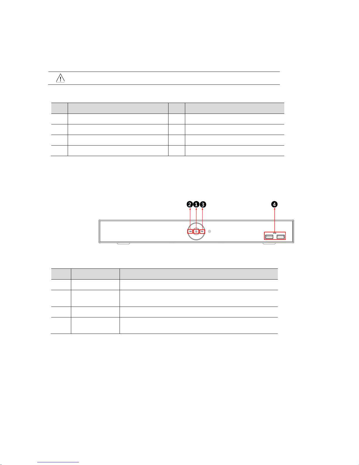
Figure 1-1 Name and Connection of each front section
Table 1-2 Name and Function of each front section
No. Name Function
1 Power status LED Pointing out device on/off.
2
Recording status
LED
Pointing out recording in process.
3 Network LED With a network viewer, pointing out network in connection.
4 USB port
USB port is connected for USB mouse or firmware up gra de, an d dat a
back-up.
Page 9
5
4ch DVR
8ch DVR
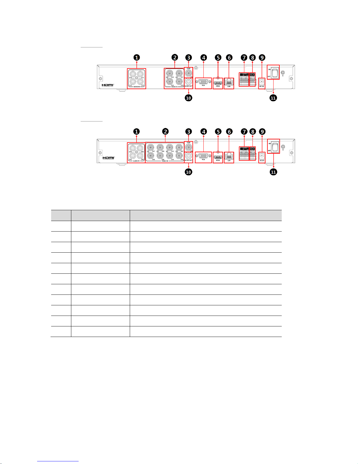
Figure 1-2 Name and Connection of each rear section of 4ch and 8ch DVR
Table 1-3 Name and Function of each rear section of 4ch and 8ch DVR
No. Name Function
1 Audio In Camera audio input port.
2 Video In Camera video input port.
3 CVBS CVBS output port (depending on device types).
4 VGA VGA output port.
5 HDMI HDMI output port.
6 LAN
Network connector.
7 Alarm In/Out Alarm connector.
8 RS485 RS-485 communication connector.
9 DC12V Connector with power supply.
10 Audio Out Audio output port.
11 Power Switch Power On-Off.
Page 10
6
2. Installation
This chapter describes the way to install DVR.
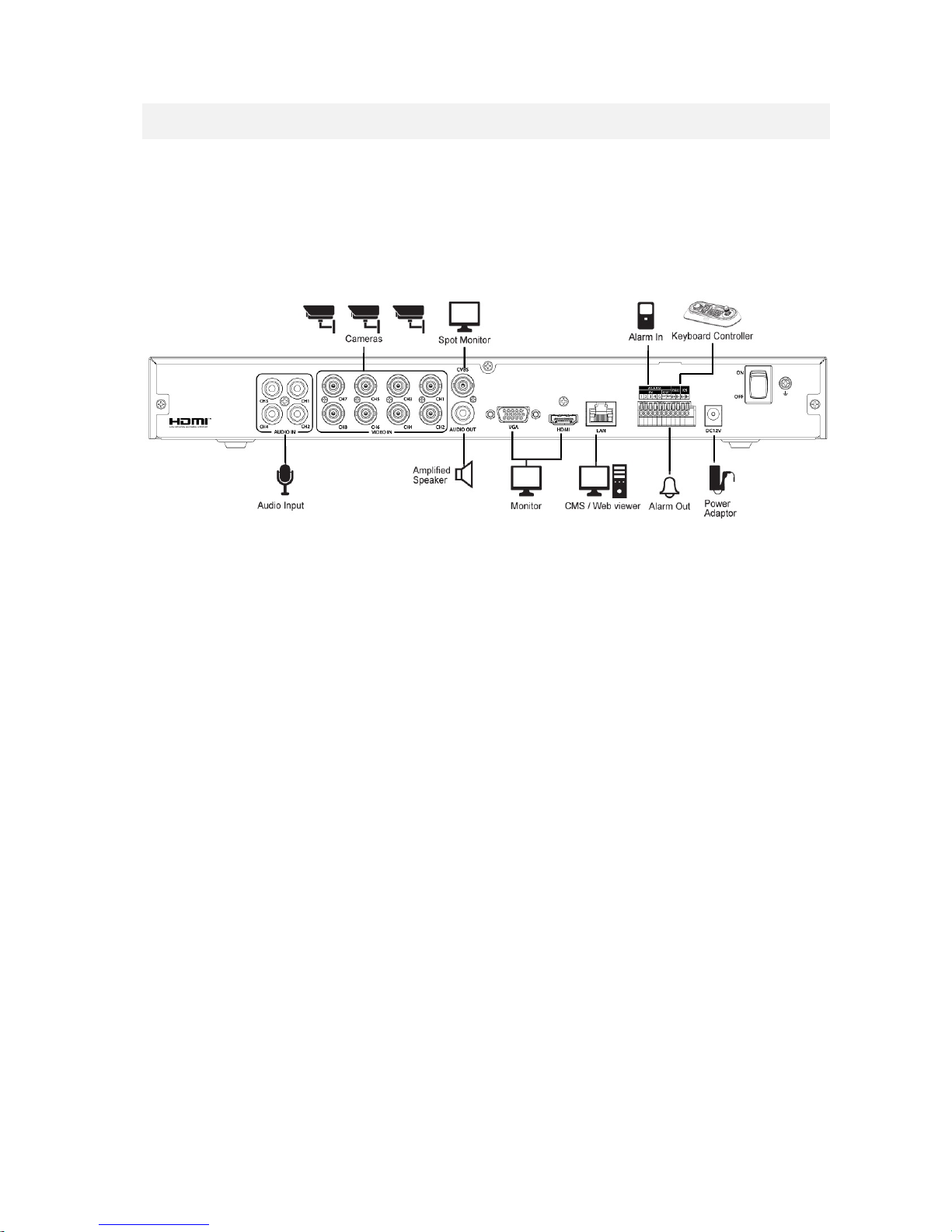
When installing a device, connect rear of the device with each port on the basis of below connection map.
Figure 2-1 Connection map
The device starts first like below sequences:
1
Installing HDD.
2
Connecting with an exterior device.
3
Starting a system.
4
Setting a quick setup.
Page 11
7
2.1 Installing HDD
How to install HDD in the device:
Attention
Withdraw the mains plug before installing HDD to reduce the risk of injury or
electrical shock, or device malfunction.
Make sure to check the compatibility of HDD with the device.
1
Always switch off and unplug the unit.
2
Unscrew with a screw driver (+) and open the unit cover .
3
Install HDD in the bottom case.
4
Connect a data cable and power cable with HDD.
5
Close the cover and tighten screws.
2.2 Connecting with Exterior Device
How to connect each port to rear section of the unit:
1
Place the unit in a stable flat surface.
2
Make a room between front/rear sides of the device not to break connectors.
Warning
Do NOT install the device too close to the wall. Protrusive connects rear the unit
may be forcedly curved or pressed, which cause fires, electric shocks, or injury.
3
Check to switch off and unplug the unit.
Warning
Make sure to withdraw the mains plug before installing the device.
4
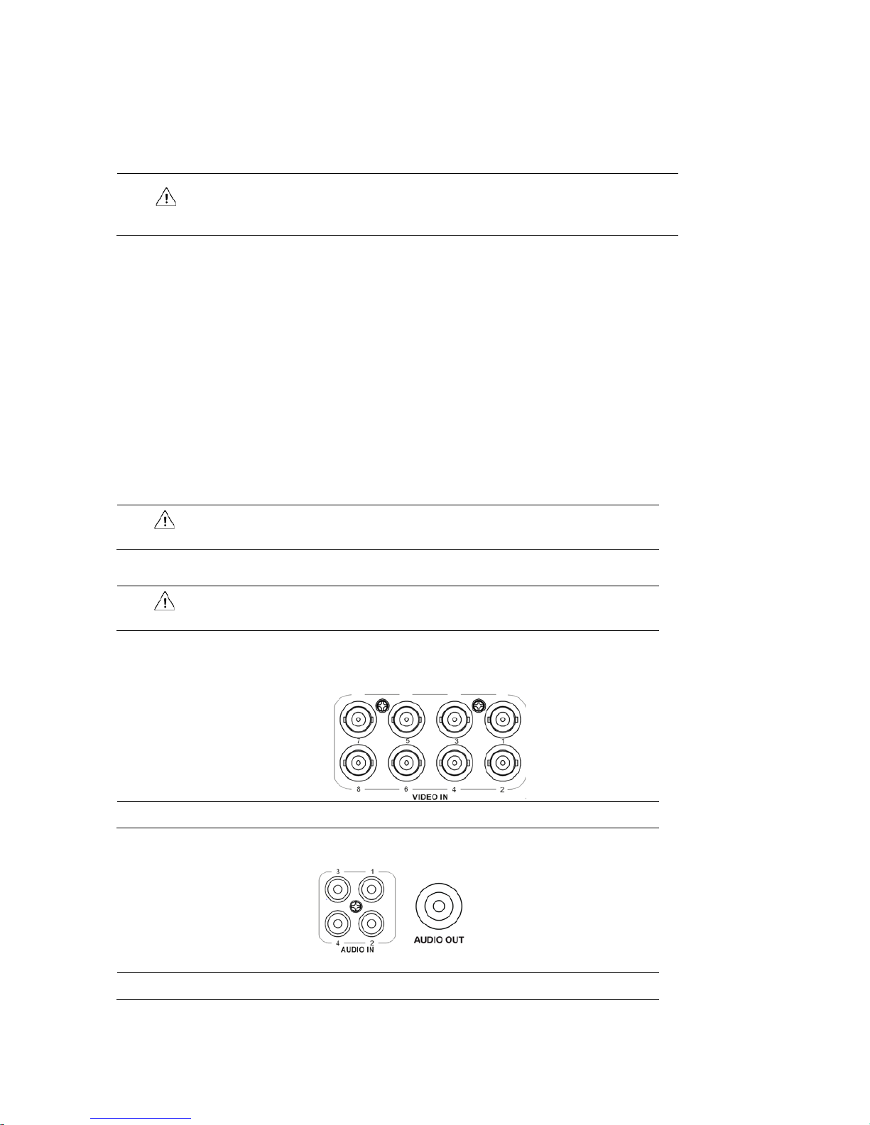
Connect input ports of camera.
Note
Connecting a camera port with the unit automatically detects the camera.
5
Connect an audio input port with a Mic and output port with a speaker.
Note
Assure regulations in the area whether recording to be legal or not.
Page 12
8
6
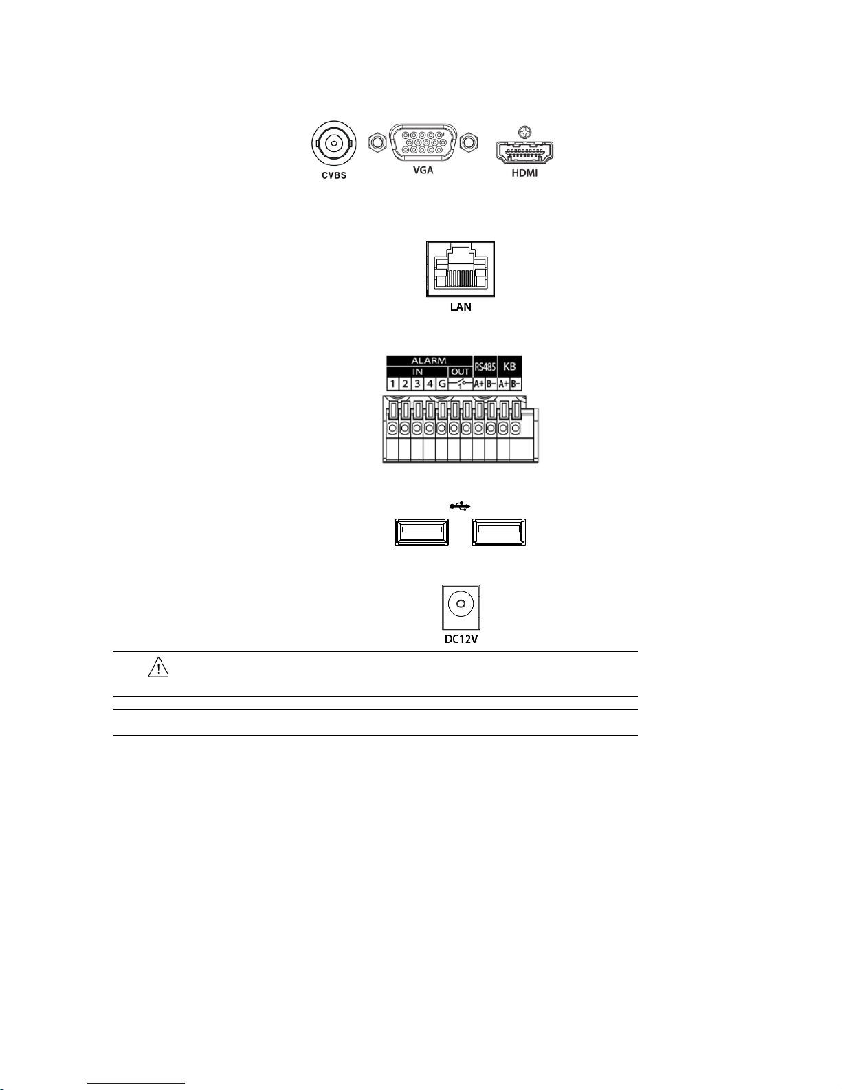
Connect a monitor with VGA, HDMI or CVBS port.
7
Connect a network port.
8
Connect an alarm and RS485 devices.
9
Connect USB port in front section of the unit with a mouse.
10
Supply the main power after completion.
Attention
Before connection, match socket with adapter pins.
Note
No power button; supplying the main power automatically starts running the unit.
Page 13
9
2.3 Starting System
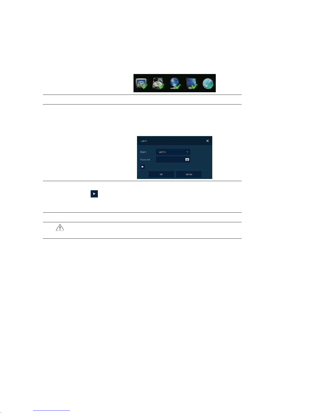
Power supply begins with system operation as follows:
1
Switching on initialize with below icons in order.
Note
Installing new HDD might take more initialize time.
2
With buzzer sounds, the start screen is presented.
3
In Log in screen, enter the ID, Password and press OK.
Note
Default ID & Password is admin/admin.
Click to see the MAC address.
If lost password, inform the MAC address to supplier to create temporary
password.
Attention
Please change password after login due to security.
Page 14
10
2.4 Quick Setup
First start of the system operates Easy Installation as follows:
1
Account
2
System
3
Network
4
Time/Date
5
Record
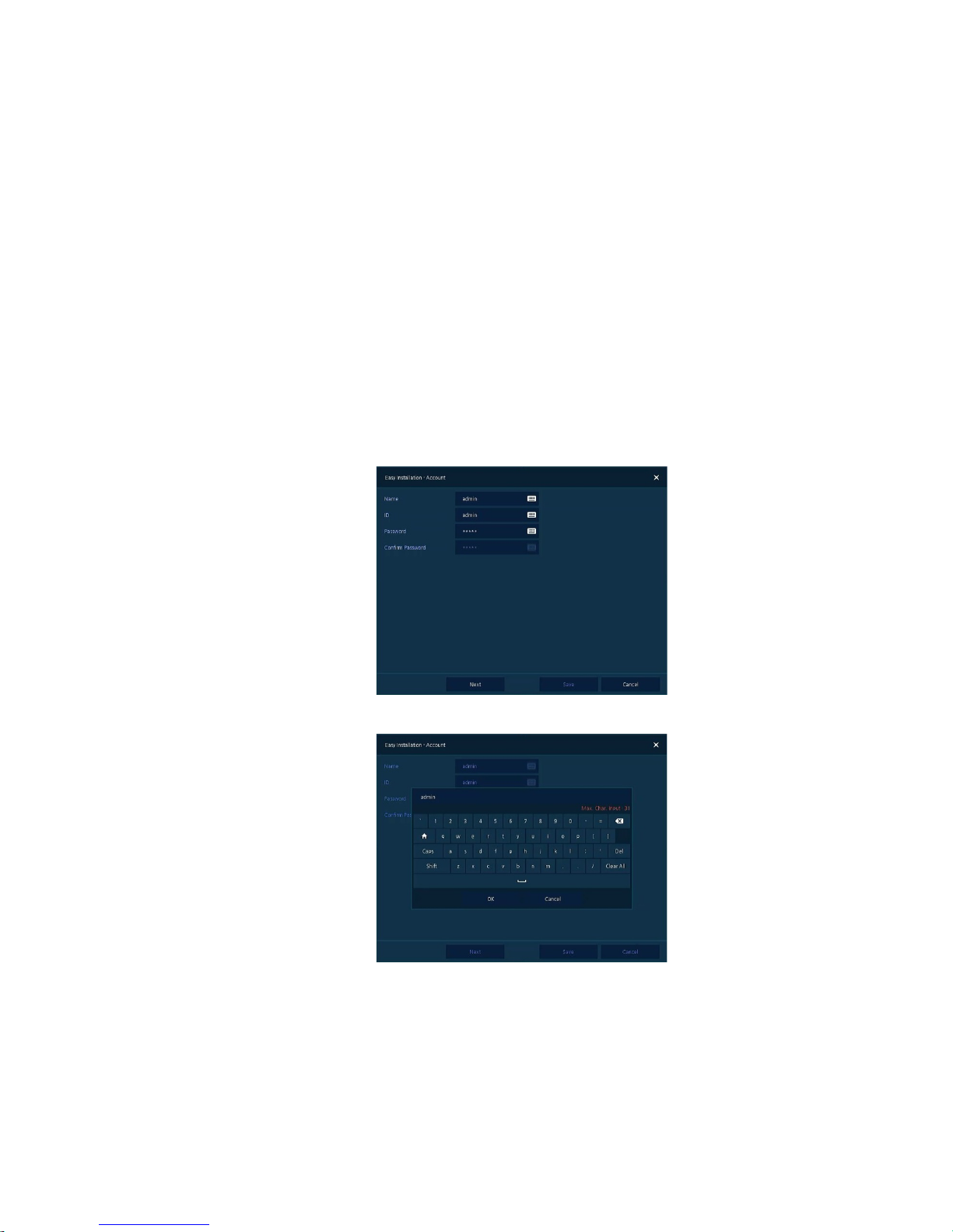
2.4.1 Account
How to set Account of Easy Installation:
1
Click the keyboard icon to set ID and Password users want.
2
With keyboard UI, set the ID and Password, and press OK.
3
Press the Save button to save newly set ID and Password.
4
Press Next button to end Account setting and move the next setting phase.
Page 15
11
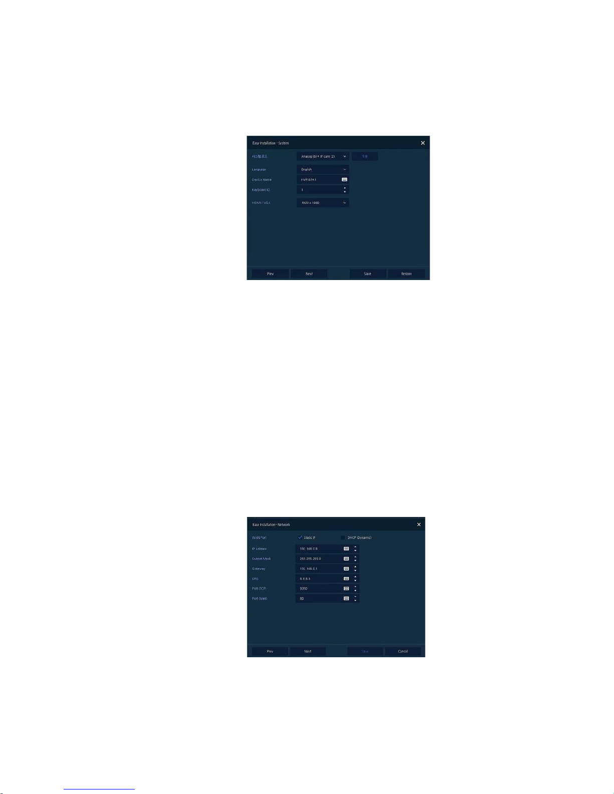
2.4.2 System
How to set the system of Easy Installation:
1
Set each item in System setting screen.
System Mode: Select input video type(Analog Only or Analog+IP cam)
Language: Select system language.
Device Name: Enter the device name.
Keyboard ID: To identify device usages in controlling DVR with RS485 through a keyboard
Selecting the device ID. In case of simultaneous use of equipment, set ID with difference.
HDMI/VGA: Set resolution of a monitor connected to the device.
2
Press Save button to s ave set value.
3
Press Next to end System setting and move the next setting phase.
2.4.3 Network
How to set the network of Easy Installation:
1
Set each item in Network setting screen.
WAN Port: Select whether to use static IP or dynamic IP.
IP Address, Subnet Mask, Gateway , DNS, and Port: As for dynamic IP, enter information in each
space.
Page 16
12
2
Press Save button to s ave set value.
3
Press Next to end Network setting and move the next setting phase.
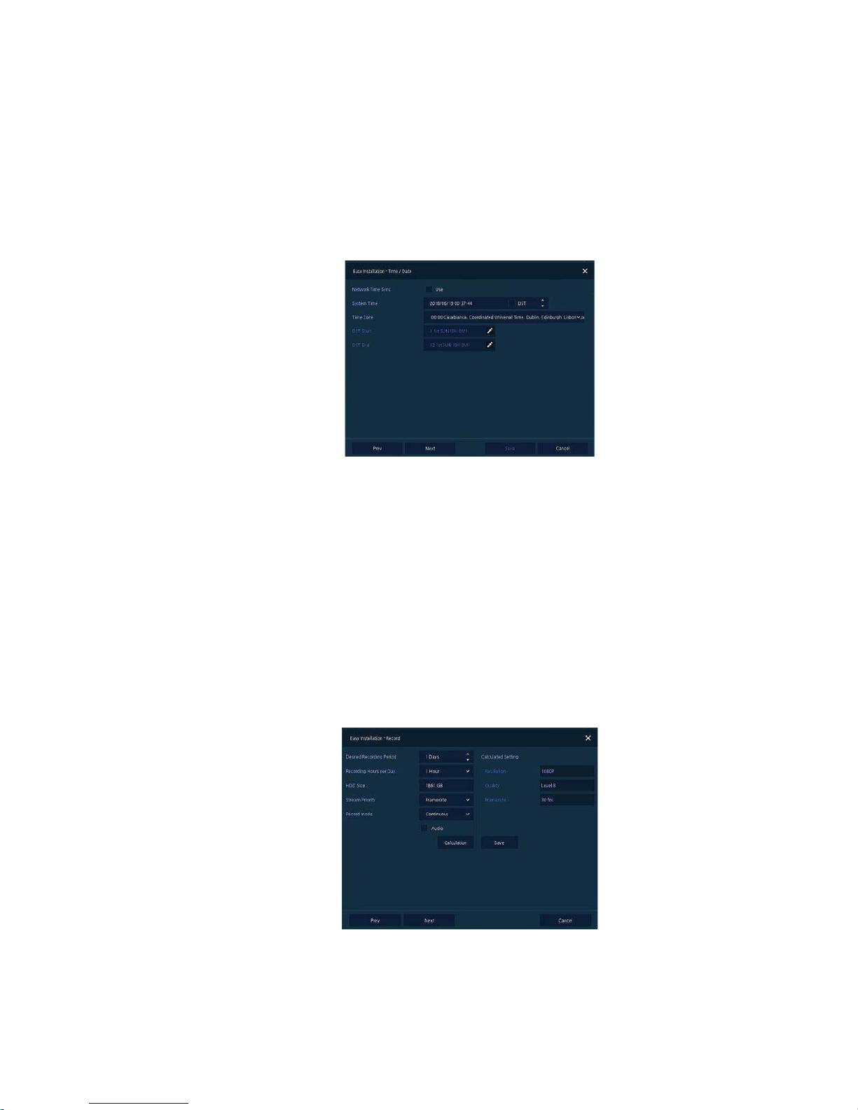
2.4.4 Time/Date
How to set the time/date of Easy Installation:
1
Set each item in Time/Date setting screen.
Network Time Sync: Select network for synchronizing with time server.
System Time: Not for synchronizing with network time server, set the device time; otherwise
(applying for Daylight saving time), select DST.
Time Zone: Select time zone for the system being installed.
DST Start/End: For applying Daylight saving time, set the application period.
2
Press Save button to s ave set value.
3
Press Next to end Time/Date setting and move the next setting phase.
2.4.5 Record
How to set the record of Easy Installation:
1
Set each item in Record setting screen.
Select desired recording period and daily recording hours.
HDD size will be displayed automatically.
Page 17

13
Select priority of frame rate or resolution.
Select recording modes as continouse or event.
Select if audio record or not.
Click Calculation to see recommended frame rate and resolution.
2 Press Save button to save set value.
3
Press Next to end Network setting and move the next setting phase.
2.4.6 Easy Installation Wizard
1
Select to run Easy Installation every time when the system start.
2
Press Save button to save set value and end Easy Installation.
Page 18
14
3. Live Screen Configuration
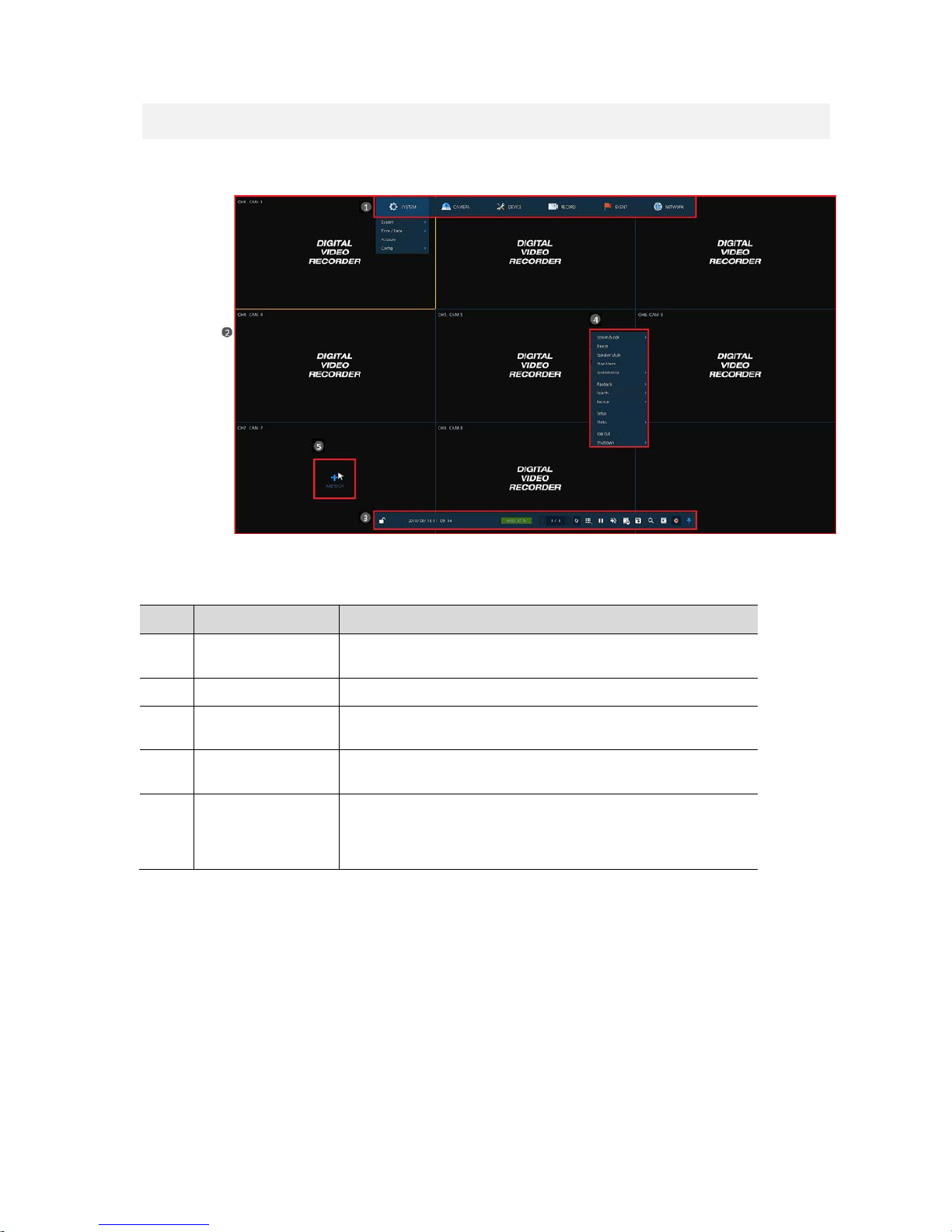
UI screen is configured like below figure.
Figure 3-1 UI Screen Configuration
Table 3-1 Items and Description of UI Screen Configuration
No. Item Description
1
Setup menu
Setting menu is located in the corner of upper screen. See “4 Setup
menu” to display detailed information about the setting menu.
2 Live screen Show live video of connected cameras.
3 Launcher menu
Launcher menu is located in the corner of below screen. See “3.2 Live
Launcher ” to display detailed information about the launcher menu.
4 Quick menu
Clicking the right button of a mouse displays Quick menu. See “3.3
Quick menu” to display detailed information about the quick menu.
5 Add to CH
It is manual registration menu when the mouse pointer is placed in
the center of the channel that the camera is not registered in Analog+
IP cam mode. See “3.3.2 Camera Registration” to display detailed
information about Add to CH.
Page 19
15
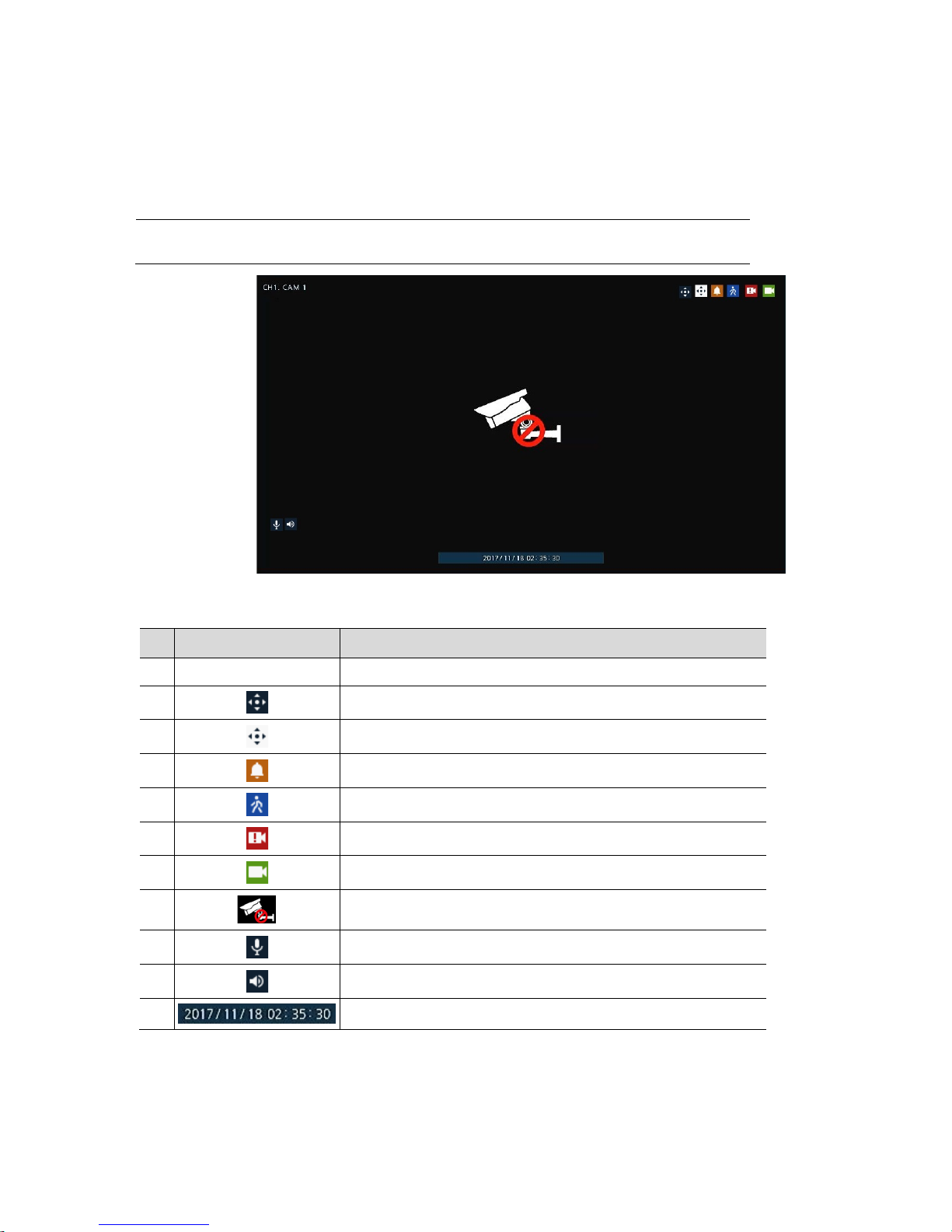
3.1 Icons in Live screen
Each icon in the live screen displays a present setting status or a function. UI screen consists of like
below.
Note
Chosen live screen is marked as a blue frame; mouse-located live screen is marked
as yellow one.
Figure 3-2 Live screen icon
Table 3-2 Live screen icon and its description
No. Icon Description
1 CH1 CAM1 Channel numbers and camera titles.
2
A camera with PTZ function.
3
PTZ control function in process.
4
Recording in alarm event mode.
5
Recording in motion event mode.
6
Recording in panic recording mode.
7
Recording in consecutive recording mode.
8 Video loss icon.
9
Mic on/off.
10
Speaker on/off.
11
Displaying present time and date.
Page 20
16
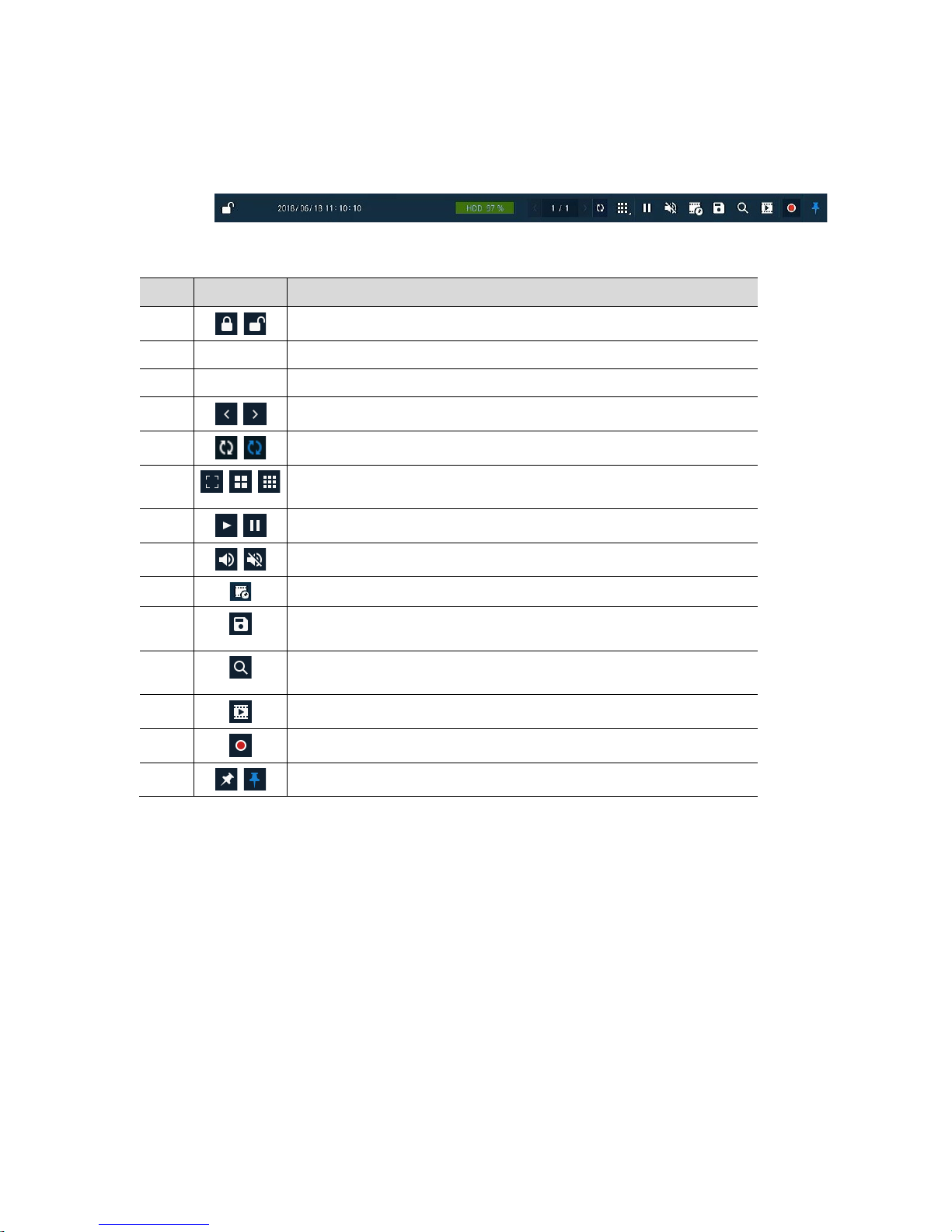
3.2 Live Launcher menu
This chapter describes Launcher menu in the bottom of the screen.
Figure 3-3 Launcher menu
Table 3-3 Launcher menu Item and Description
No. Item Description
1
Log in/out status and logged in ID.
2 Date & Time Displaying present date and time.
3 HDD Disp lay ing HDD capacity in use.
4
Moving to previous/next partition screen.
5
Displaying live screen in order set (toggle).
6
Selecting partition mode to mark in live screen (single screen, 4- and 9partition).
7
Stopping or replaying selected live screen images (toggle).
8
Audio on or mute chosen live screen(toggle).
9
Save the bookmark.
10
Make a backup video of users want. See “3.2.1 Backup” to display detailed
information about back-up.
11
Searching recording data (time, event, thumbnail, smart search and text). See
“5.1 Search” to display detailed information abo u t search.
12
Playback recorded data.
13
Starting immediate recording of selected channel.
14
Locking or releasing launcher menu (toggle).
Page 21
17
3.2.1 Backup
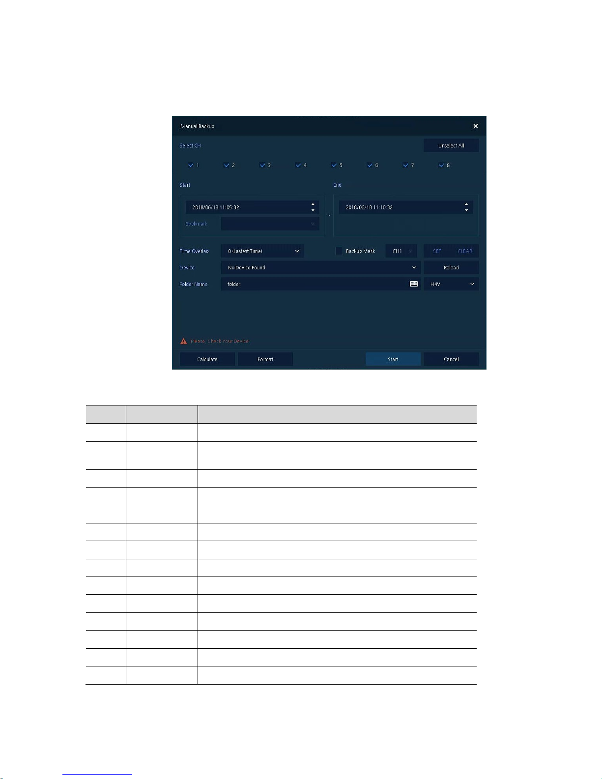
The device provides a back-up function of live screen.
Figure 3-4 Backup
Table 3-4 Backup Item and Description
No. Item Description
1 Select CH Selecting a channel users want to back-up.
2
Select All/
Unselect All
Select or clear all channels.
3 Start Setting back -up start time (Bookmark: bookmark list).
4 End Setting back-up ending time (Bookmark: bookmark list).
5 Time Overlap Selecting time if there are two recorded data in the same time.
6 Backup Mask User can mask selected area. It works H4V format only.
7 Device Selecting the device to save back-up files.
8 Reload Opening the device information.
9 Folder Name Entering a folder name to save back-up files.
10 File format Selecting a file format to back-up.
11 Calculate Calculating data capacity to back-up.
12 Format Fo r m atting the device to back-up.
13 Start Starting back-up.
14 Cancel Closing the backup screen.
Page 22
18
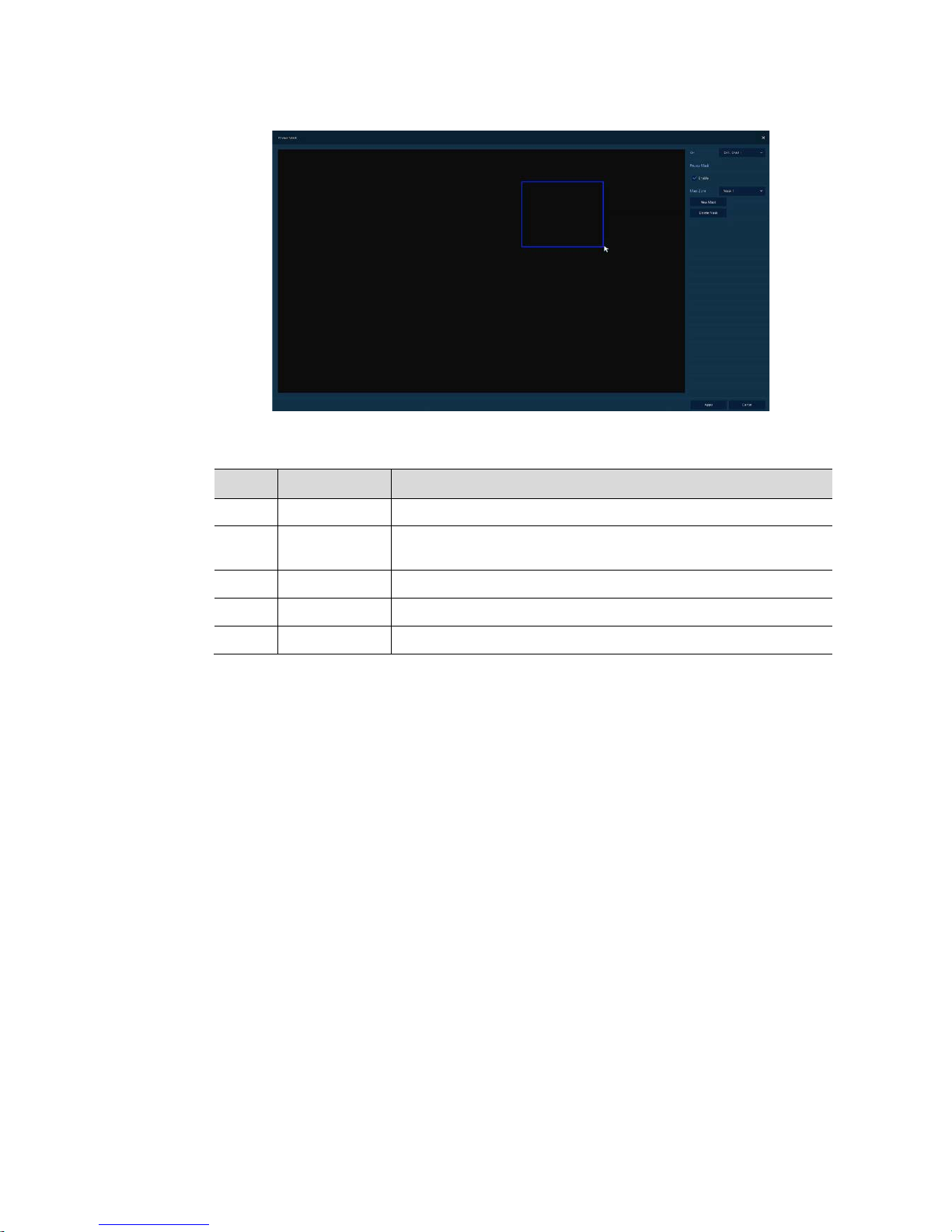
Select Backup Mask and click SET button to open the Privacy Mask pop-up window.
Figure 3-5 Backup Mask
Table 3-5 Backup Mask Item and Description
No. Item Description
1 Select CH Select the channel to set the privacy zone.
2
Privacy Mask
Enable
Select whether to use the Privacy Mask.
3 Mask Zone Apply all or only the selected mask.
4 New Mask Create a new privacy zone. Up to 4 masks can be created.
5 Delete Mask Delete all or selected privacy zones.
Page 23
19
3.3 Quick menu
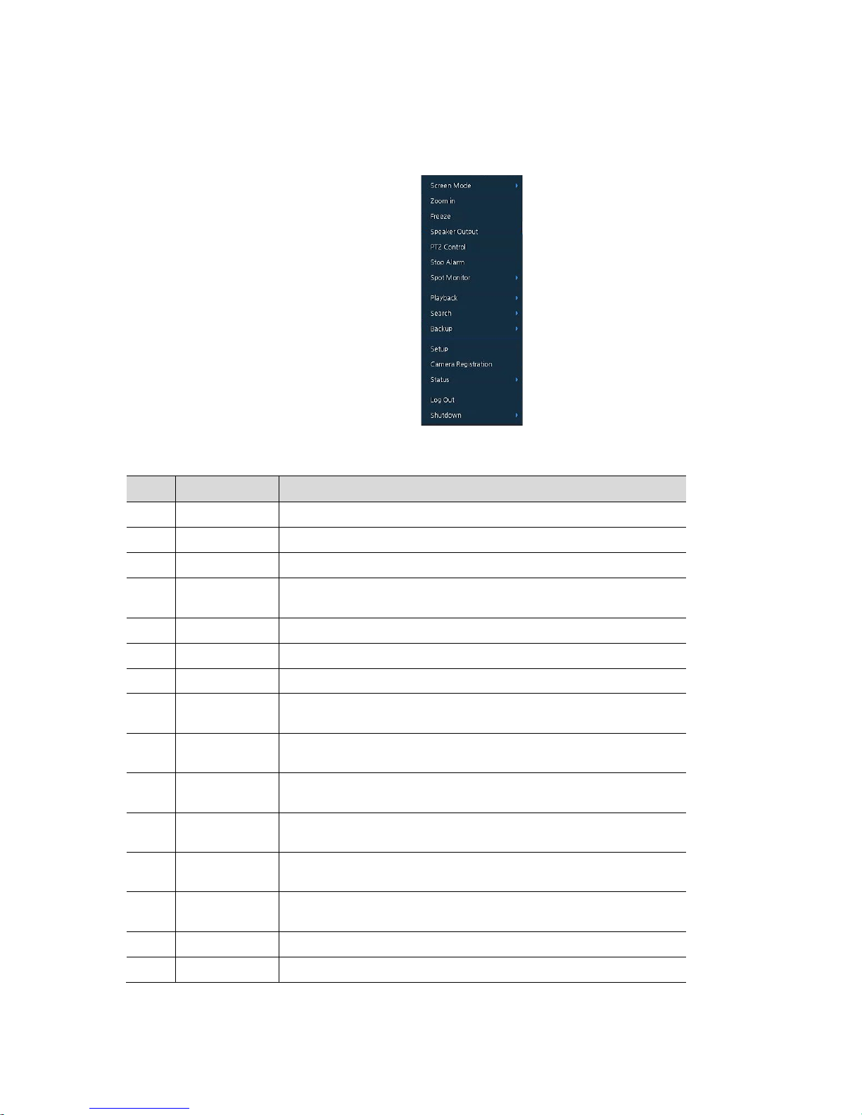
This chapter depicts Quick menu when users click the right button of the mouse in live screen.
Figure 3-6 Quick menu
Table 3-6 Quick menu Item and Description
No. Item Description
1 Screen Mode Selecting the partition mode of live screen (Full, 2X2 and 3X3).
2 Zoom in Magnifying selected live screen (Zoom out, 2 times, 4 times, and 8 times).
3 Freeze Freezes the video selected live screen images (toggle on/off).
4
Speaker
Output/Mute
Turning on/off a sound speaker.
5 PTZ Control Controlling PTZ function.
6 Stop Alarm Stopping monitoring alarm output and event.
7 Spot Mode Set the output mode of a spot monitor (Auto, Full, and 3x3).
8 Playback
Playing selected live screen images (before 30 sec, 1 min, 5 min, 10 min,
30 min, 1-hour, Go to last play time, and Go to last record time).
9 Search
Searching recording data (time, event, thumbnail, and text). See “5.1
Search” to display detailed information about search.
10 Backup
Backup video users want. See “3.2.1 Backup” to display detailed
information about back-up.
11 Setup
Opens the DVRs main set up menu.. For more information about setting
menu, see section “4 Setup menu”.
12
Camera
Registration
Opens a pop-up menu for IP camera registration.
13 Status
Opens a pop-up menu showing: device system log, event, and recording
status (system log, event, and record).
14 Log in/Log out Log in/L og out .
15 Shutdown Shuts down or restarts the device (shutdown, restart).
Page 24
20
3.3.1 PTZ Control
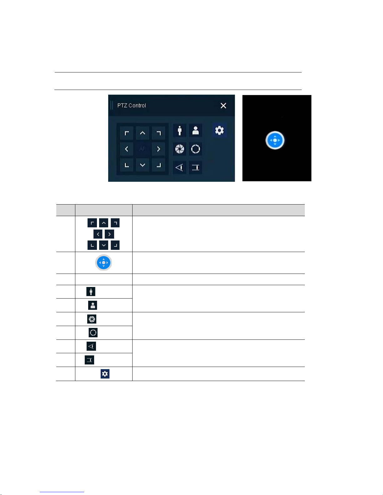
The location of images may be moved to monitor with PTZ ball.
Note
PTZ Control menu can be displayed if relevant channel’s protocol is set in DEVICE >
PTZ in the upper live screen.
Figure 3-7 Quick menu > PTZ Control
Table 3-7 Quick menu > PTZ Control Item and Description
No. Item Description
1
Moving images with direction buttons.
2
Moving images with PTZ ball.
3 AF Adjusting screen focus automatically .
4
Zoom Out
Zoom function of PTZ camera.
5
Zoom In
6
IRIS OFF
Adjusting iris in the camera.
7
IRIS On
8
Focus Far
Manual focus adjustment.
9
Focus Near
10 Open camera menu.
Page 25
21
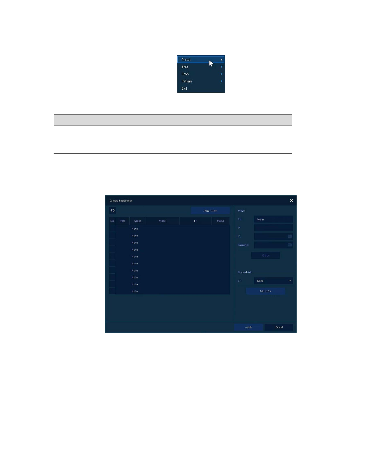
In PTZ Control screen, clicking the right button of the mouse displays Quick menu.
Figure 3-8 PTZ Control Quick menu
Table 3-8 PTZ Control Item and Description in Quick menu
No. Item Description
1
Preset, T our,
Scan, Pattern
Run PTZ functions.
2 Exit Transforming to live screen menu in PTZ Control menu.
3.3.2 Camera Registration
Users can register the IP cameras if user select Analog+IP mode.
Figure 3-9 Camera Registration
Page 26
22
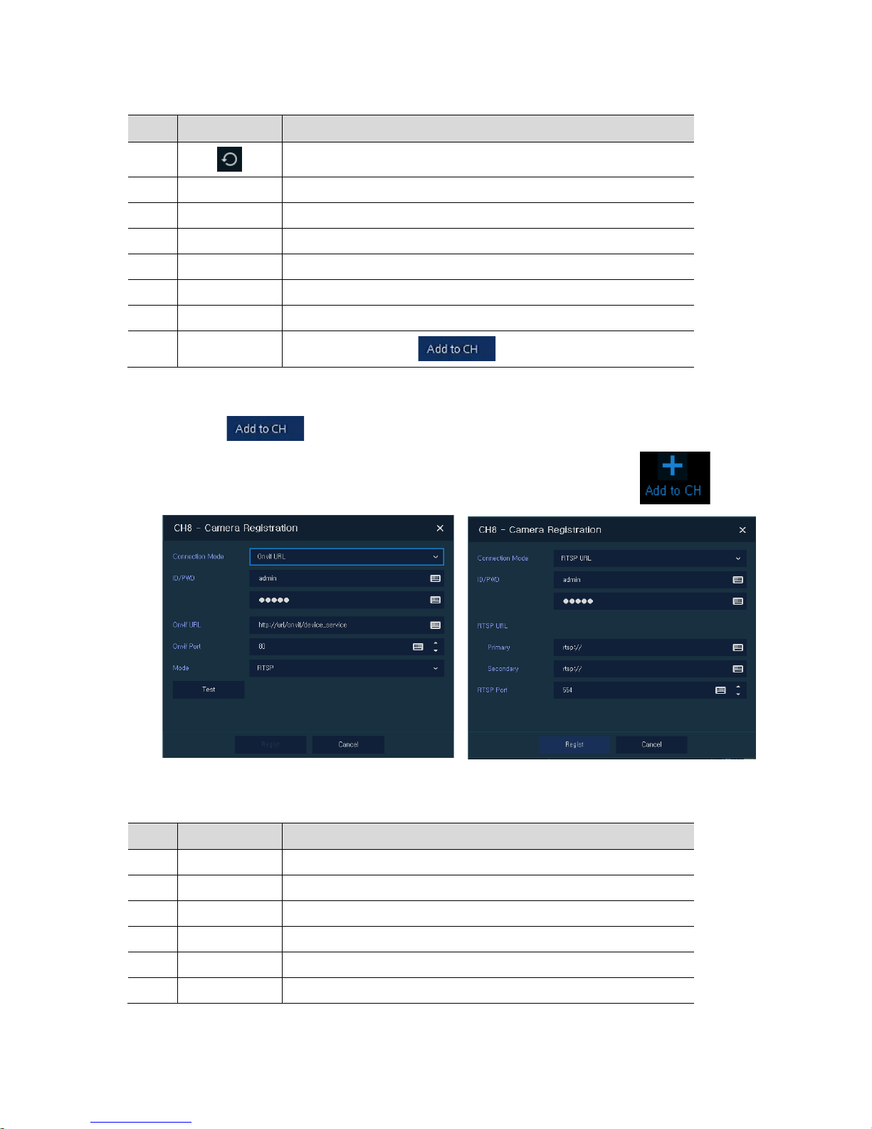
Table 3-9 Camera Registration
No. Item Description
1
Search the connected IP cameras.
2 Auto Assign Automatically assign the channel windows.
3 Port Show the detected camera port.
4 Assign Selecting the channel windows manually.
5 Model Show detected camera model number.
6 IP Show detected camera IP address.
7 Status Show connection status.
8 Add Manually
Select channel and click to open manual add window
Add Manually
Click to open Camera Registration.
Or move the mouse point at the middle of channel on the live screen and click the .
Figure 3-10 Camera Registration(manual add)
Table 3-10 Camera Registration(manual add)
No. Item Description
1 Connection Mode Select connection mode as Onvif or RTSP.
2 ID/PWD Enter ID and password of IP camera.
3 Onvif URL Enter camera IP address.
4 RTSP URL Enter Primary and Secondary RTSP IP address and URL.
5 O nvif Por t Enter web port. Default port is 80.
6 RTSP Port Enter RTSP port. Default port is 554.
Page 27
23
No. Item Description
7 Mode Select video stream format (RTSP/HTTP).
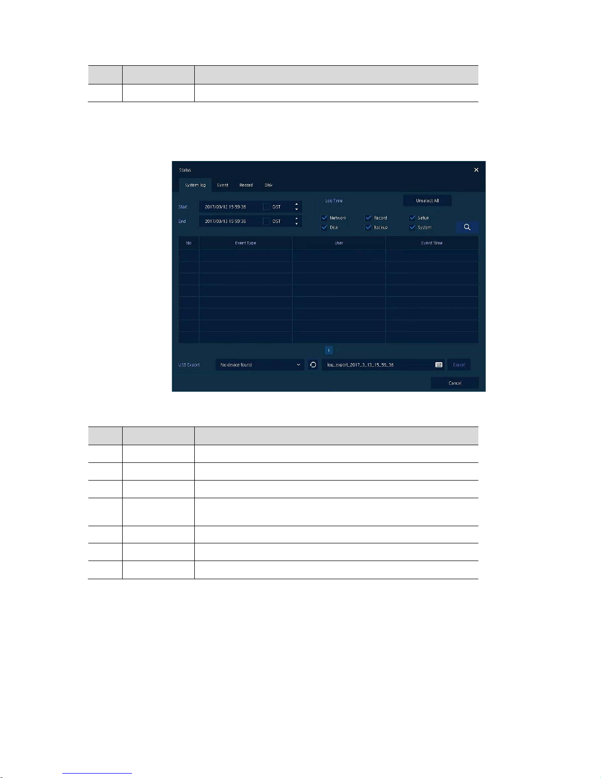
3.3.3 Status > System log
Users can see the system log information in System log tap in Status screen.
Figure 3-11 Status > System log in Quick menu
Table 3-11 Status of Quick menu > System log Item and Description
No. Item Description
1 Start Setting starting time of system log to search.
2 End Setting ending time of system log to search.
3 Log T ype Selecting log types (Network, Record, Setup, Disk, Backup, and System).
4
Select All
/Unselect All
Selecting or clearing all log types (toggle).
5 Search Pressing search button search on the basis of set condition.
6 System log list Displaying system log list .
7 Cancel Completing the status screen.
Page 28
24
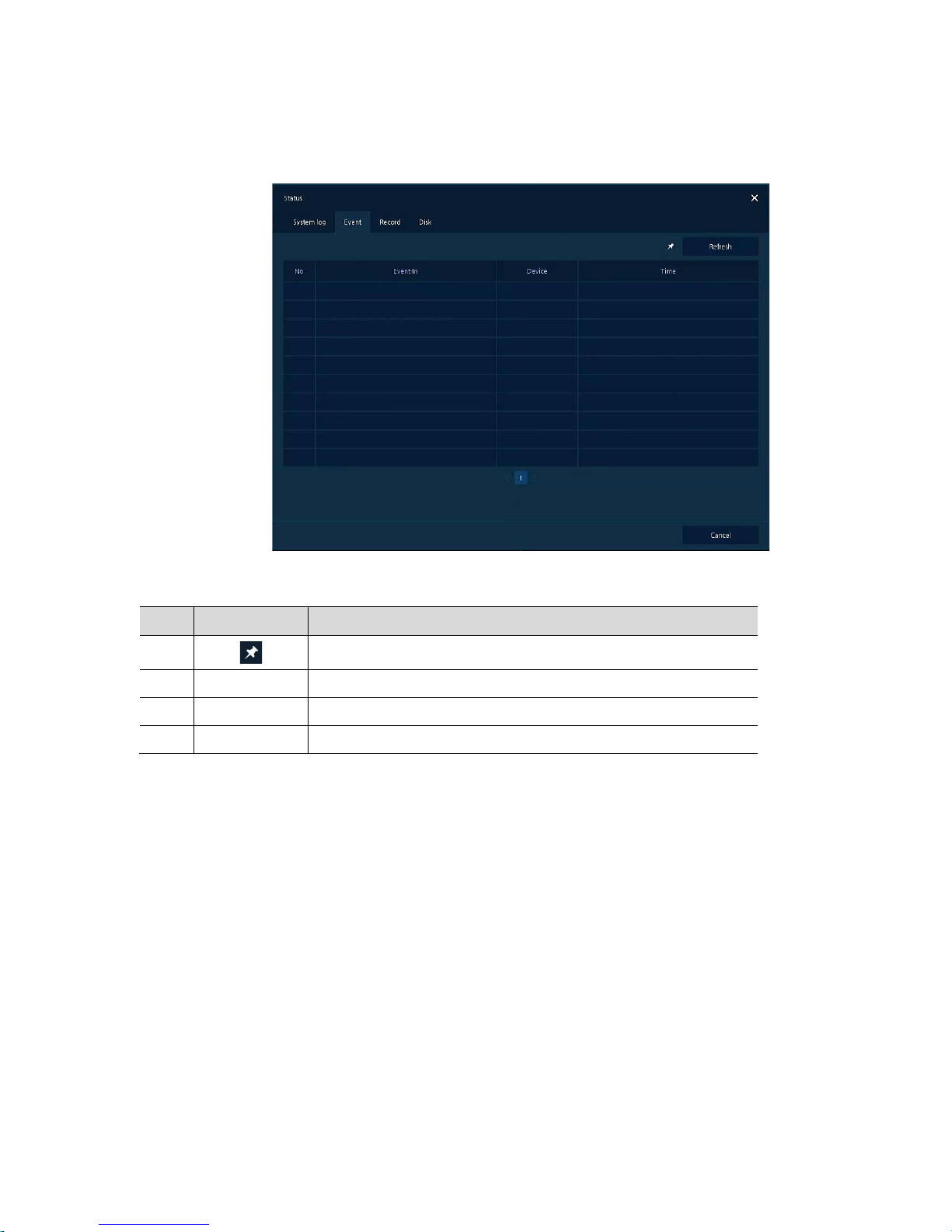
3.3.4 Status > Event
Users can see the real-time event information of the unit in Event tap in Status screen.
Figure 3-12 Status > Event in Quick menu
Table 3-12 Status > Event Item and Description in Quick menu
No. Item Description
1
Temporary fixing or releasing an event list (toggle).
2 Refresh Deleting the event list.
3 Event list Displaying the event list.
4 Cancel Completing the status screen.
Page 29
25
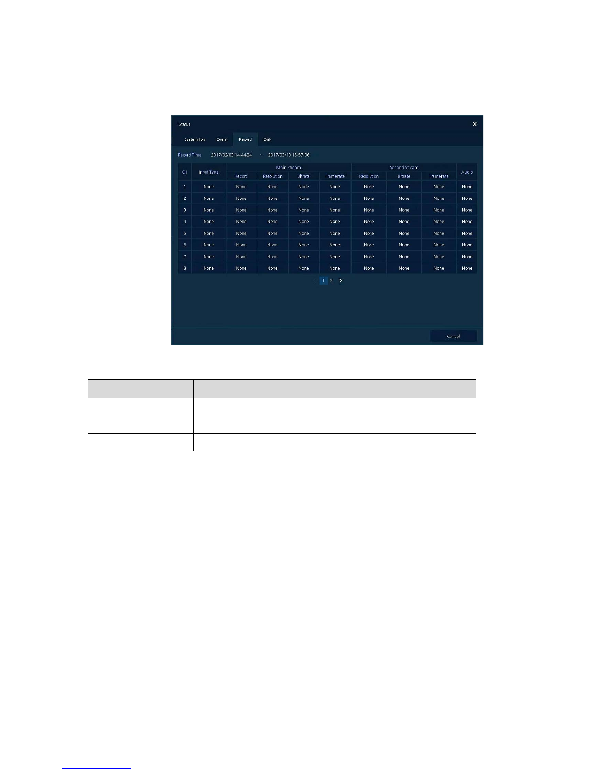
3.3.5 Status > Record
Users can see the recording status in Record tap in Status screen.
Figure 3-13 Status > Record in Quick menu
Table 3-13 Status > Record Item and Description in Quick menu
No. Item Description
1 Record time Marking recorded period.
2 Record list Displaying the record setting status.
3 Cancel Completing the status screen.
Page 30
26
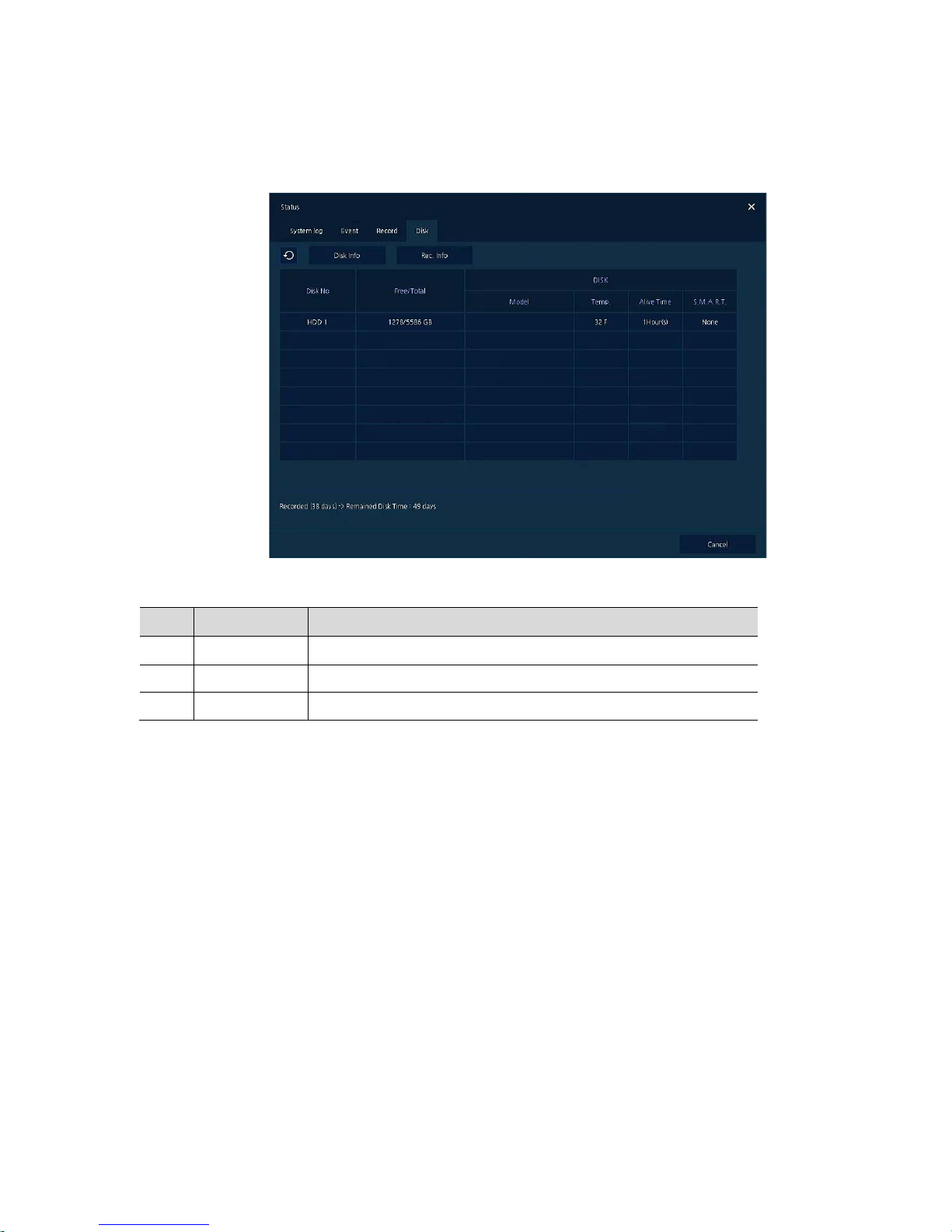
3.3.6 Status > Disk
Users can see the disk status in Disk tap in Status screen.
Figure 3-14 Status > Disk in Quick menu
Table 3-14 Status > Disk Item and Description in Quick menu
No. Item Description
1 Disk Info Display disk temperature and S.M.A.R.T information.
2 Rec. Info Display recording period.
3 Cancel Completing the status screen.
Page 31
27
4. Setup menu
This chapter describes Setup menu in the upper side of the screen.
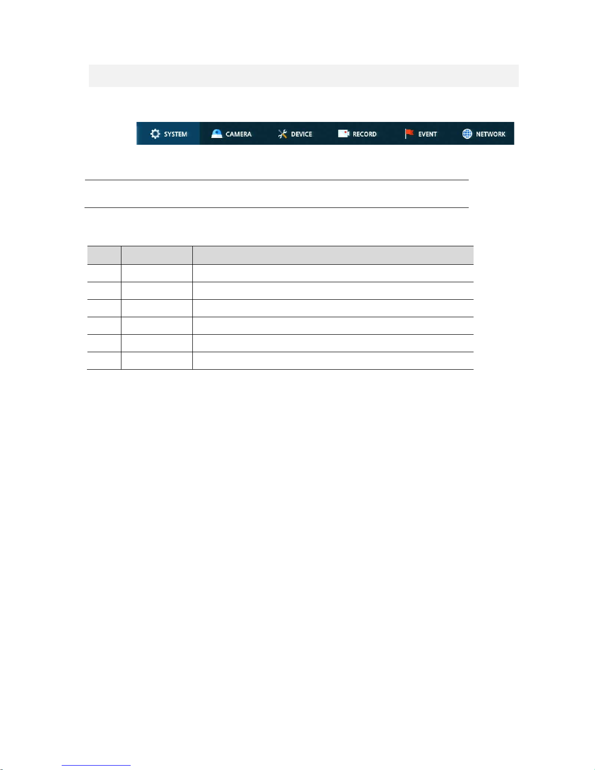
Figure 4-1 Setup menu
Selecting the menu opens the setting screen.
Note
Setup screen is available to click Setup in Quick menu by clicking the right button
of the mouse.
Table 4-1 Setup menu Item and Description
No. Item Description
1 SYSTEM S etting the system envi ronment.
2 CAMERA Setting the camera.
3 DEVICE Setting the non-camera device connected with the DVR.
4 RECORD Setting the recording parameters.
5 EVENT Setting each event.
6 NETWORK Setting the network environment.
Page 32

28
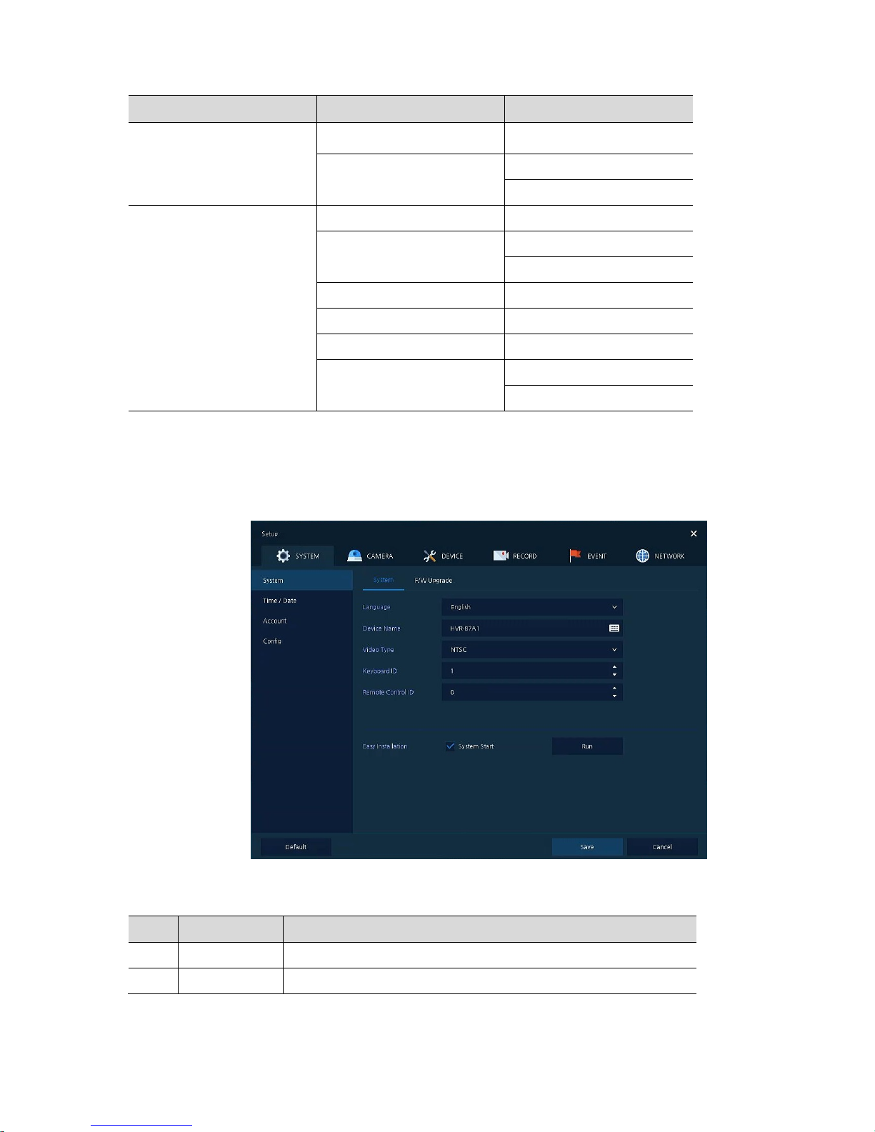
Setup menu includes:
Table 4-2 Setup menu tree
1 Depth 2 Depth 3 Depth
SYSTEM
System
System
F/W Upgrade
Time/Date
Time/Date
Holiday
Account User
Configuration
Export/Import
Factory Default
CAMERA
Basic
Basic
Audio In/Out
Advanced
Scan Mode
Advanced
DEVICE
Display
Display
Spot
OSD
Sequence
Disk
Setup
iSCSI
PTZ PTZ
Serial Device Serial Device
TEXT TEXT
RECORD
Schedule
Schedule
Quick
Stream
Main Stream
Sub Stream
Panic
EVENT
System/Disk
System
Disk
Alarm In
Setup
Schedule
Motion
Setup
Schedule
Page 33
29
1 Depth 2 Depth 3 Depth
Video Loss Setup
Notification
Periodic
Schedule
NETWORK
Basic WAN Port
DVRNS/DDNS
DVRNS/Dashboard
DDNS
E-Mail E-Mail
FTP FTP
P2P P2P
Notification Server
Notification Server
Notification Message
4.1 General buttons in Setup menu
This section depicts General buttons in Setup menu.
Figure 4-2 General buttons in Setup menu
Table 4-3 Item and Description of General buttons in Setup menu
No. Item Description
1 Default Reverse changed setting value to default in factory.
2 Save Save the set content.
Page 34
30
No. Item Description
3 Cancel Cancel the set value.
4 Restore Cancel the set value, and reverse it to default.
5 Apply Apply the content set.
4.2 SYSTEM
In SYSTEM, basic system environment is set.
4.2.1 System
Set and upgrade the basic items of the system.
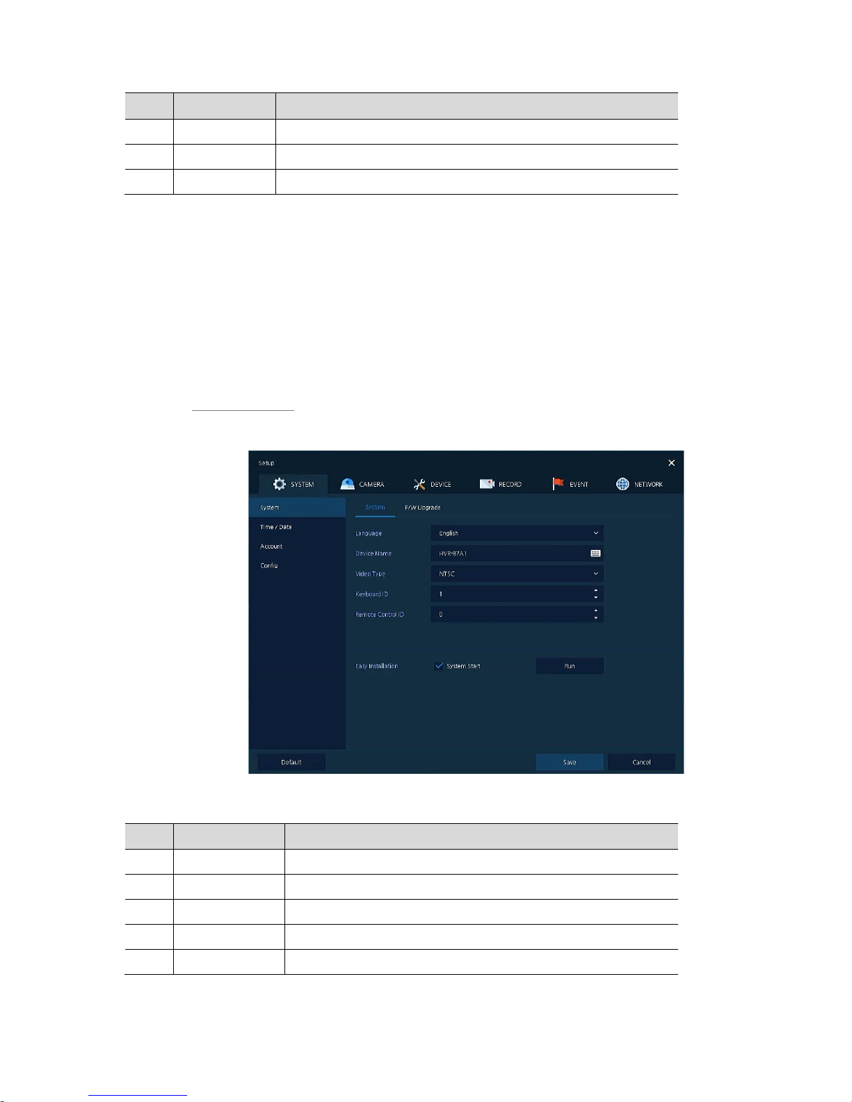
System > System
Set the basic items in the System.
Figure 4-3 SYSTEM > System > System
Table 4-4 SYSTEM > System > System Item and Description
No. Name Function
1 Language Set the system language.
2 Device Name Enter the device name (Only English is possible).
3 Video Type Select image standard types (NTSC, PAL).
4 Keyboard ID Select keyboard ID (1~255).
5 Remote Control ID Select wireless remote control ID (1~99).
Page 35
31
No. Name Function
6 System start Select Easy Installation in starting the system.
7 Run Run Easy Installation.
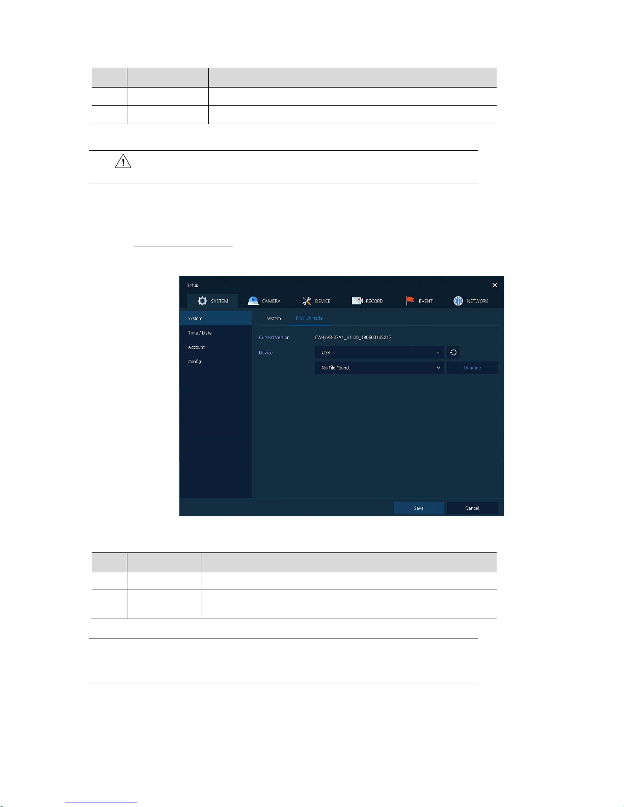
System > F/W Upgrade
Set the upgraded items of the system.
Figure 4-4 SYSTEM > System > F/W Upgrade
Table 4-5 SYSTEM > System > F/W Upgrade Item and Description
No. Name Function
1 Current Version Displaying the present tool version.
2 Device
Connect USB memory that has files to upgrade to the USB port, select files
to upgrade.
Note
If firmware version in the USB drive is lower than present system versio n ,
system does not display the firmware in the USB drive.
To upgrade through network, recorder must have HDD.
Warning
If change video type, system will reboot and all setup go to factory default.
Page 36
32
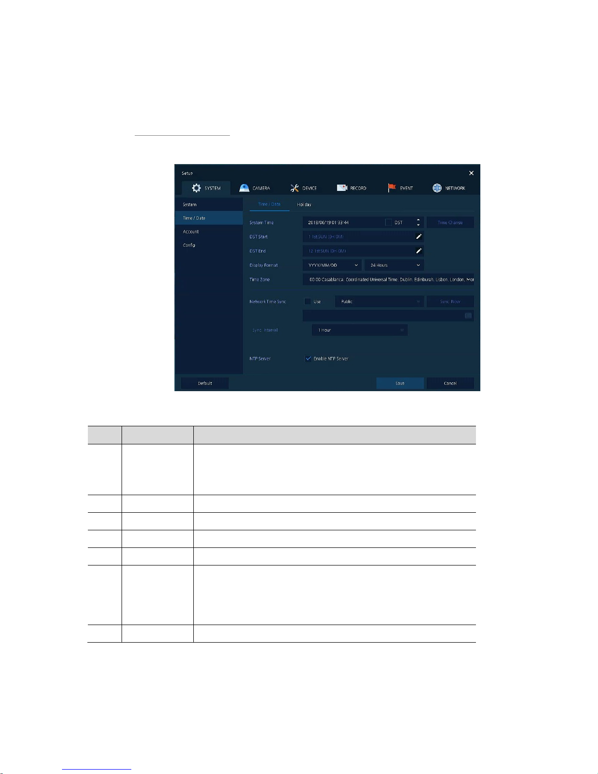
4.2.2 Time/Date
Set the date, time, and holidays of the system.
Time/Date > Time/Date
Set the date, time, and holidays of the system.
Figure 4-5 SYSTEM > Time/Date > Time/Date
Table 4-6 SYSTEM > Time/Date > Time/Date Item and Description
No. Name Function
1 System Time
Set the date and time.
DST: Select whether to use summer time.
Time change: Save changed time.
2 DST Start Set the starting date of summer time
3 DST End Set the ending date of summer time
4 Display Format Select the format to present date and time.
5 Time Zone Select time zone.
6
Network Time
Sync
For using a specific network time server, click the Use checkbox and enter
the server address.
Sync. Interval: Select synchroniz a t ion pe ri od (1~7-hour).
Last Sync. Time: Displaying the final synchronized t im e.
7 NTP Server Select whether to use NTP server.
Page 37
33
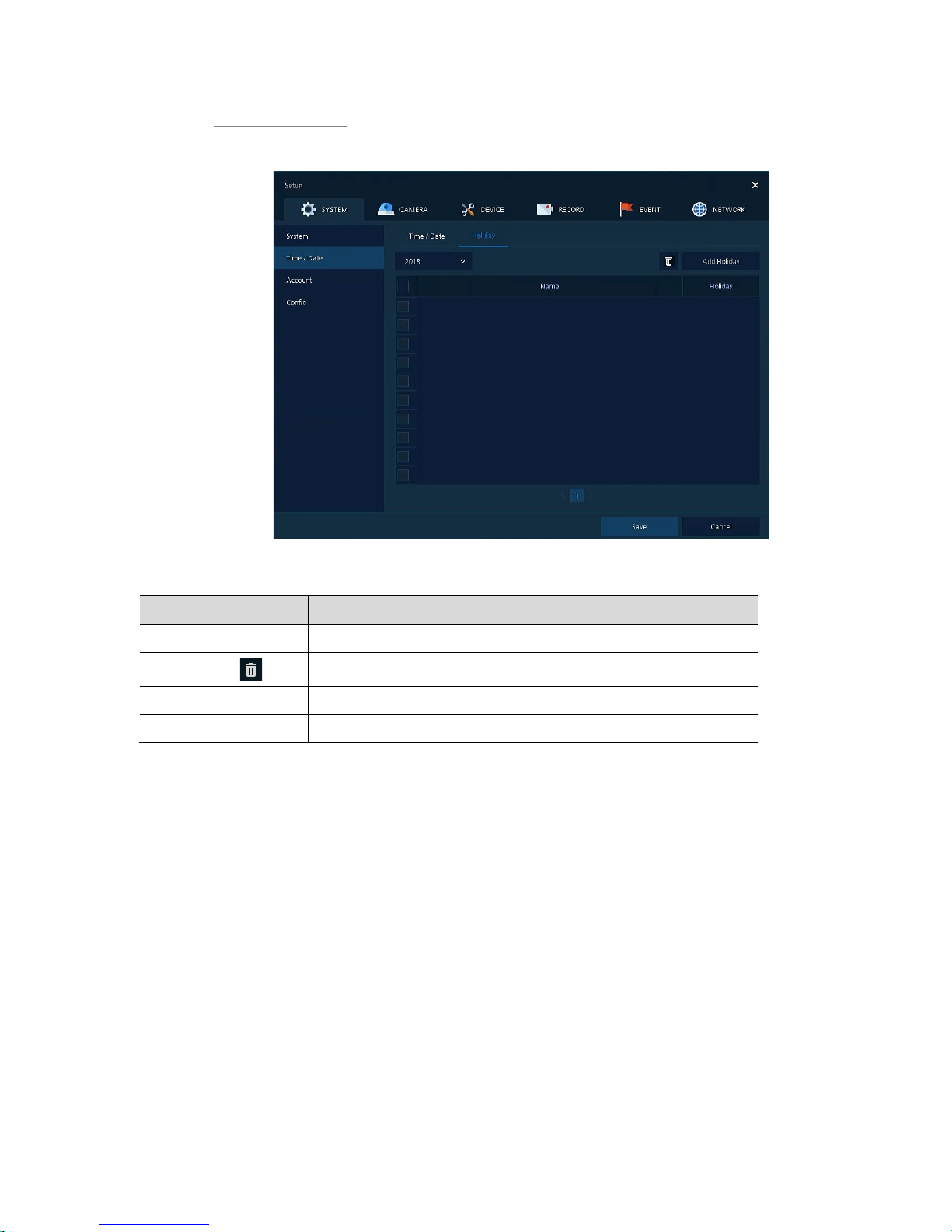
Time/Date > Holiday
Set holidays of the system.
Figure 4-6 SYSTEM > Time/Date > Holiday
Table 4-7 SYSTEM > Time/Date > Holiday Item and Description
No. Name Function
1 Year Select years to set holidays.
2
Delete selected holidays.
3 Add Holiday Add holidays.
4 List Display added holiday lists.
Page 38
34
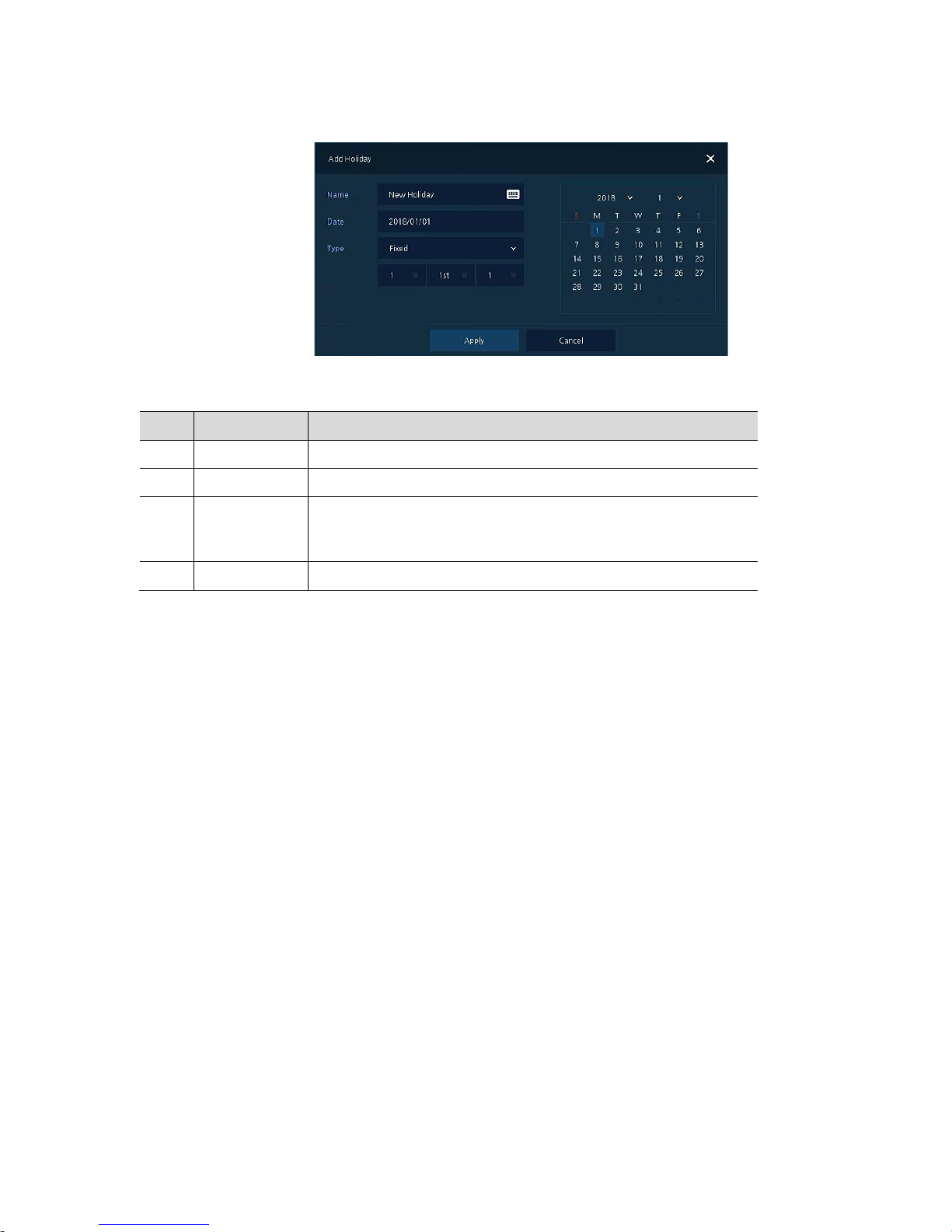
Clicking Add Holiday displays ho li d ay ad dit io n screen like below.
Figure 4-7 SYSTEM > Time/Date > Holiday > Add Holiday
Table 4-8 SYSTEM > Time/Date > Holiday > Add Holiday Item and Description
No. Name Function
1 Name Enter the holiday name.
2 Date Display chosen date.
3 Type Select the holiday types.
e.g.,) Selecting Relative and 1, first, and Sun, which designates annual
January of the 1st Sunday as a holiday.
4 Calendar Select the holiday to add.
Page 39
35
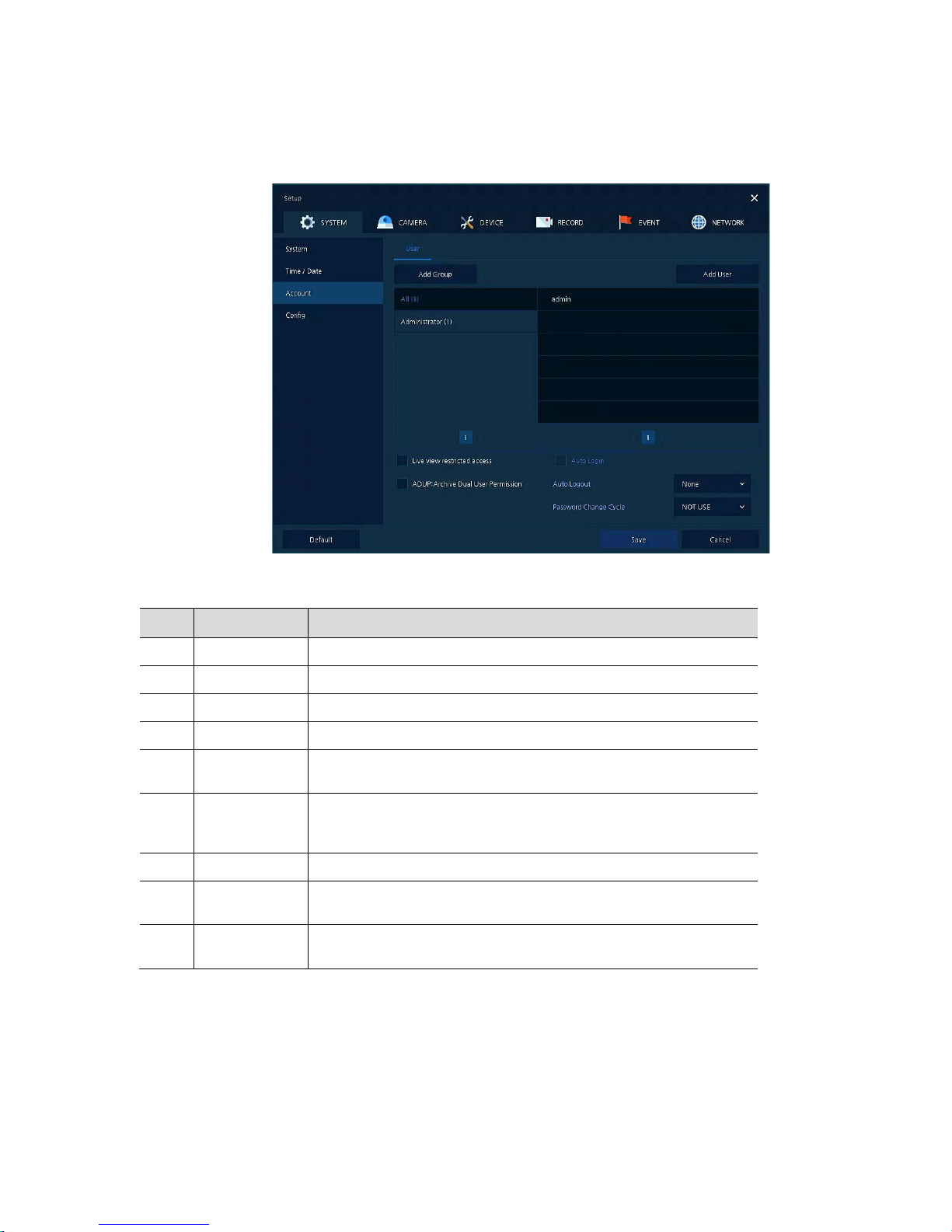
4.2.3 Account > User
Set the user’s account of the system.
Figure 4-8 SYSTEM > Account > User
Table 4-9 SYSTEM > Account > User Item and Description
No. Name Function
1 Add Group Add users’ group.
2 Add User Add users.
3 Group List Display a total group list.
4 User List Display user lists across groups.
5
Live view
restricted access
Do not display live video if log it out.
6
ADUP(Archive
Dual User
Permission)
T wo users should access to search, playback and back-up.
7 Auto Login Click/clear the automatic login checkbox.
8 Auto Logout
Select automatic logout time (Null, 1 min, 2 min, 3 min, 4 min, 5 min, 6
min, 7 min, 8 min, 9 min, 10 min, and 30 min).
9
Password Change
Cycle
If enable, user should change the password periodically.
Page 40
36
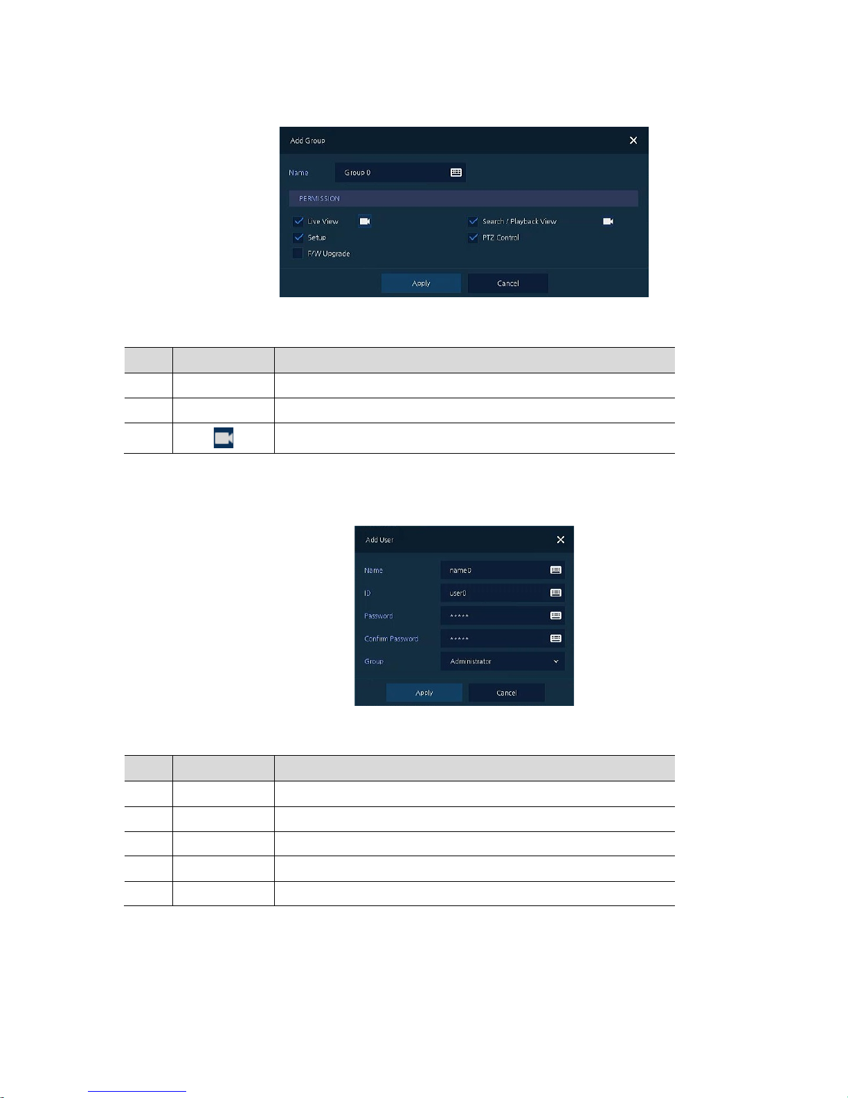
Press Add Group button, then Add Group screen displays.
Figure 4-9 SYSTEM > Account > User > Add Group
Table 4-10 SYSTEM > Account > User > Add Group Item and Description
No. Name Function
1 Name Enter the group name.
2 PERMISSION Select items to permit access.
3
Select channels to permit access.
Press Add User button, then Add User screen displays.
Figure 4-10 SYSTEM > Account > User > Add User
Table 4-11 SYSTEM > Account > User > Add User Item and Description
No. Name Function
1 Name Enter the user name.
2 ID Enter the user ID.
3 Password Enter the password.
4 Confirm Password Confirm the password.
5 Group Select to the group to which belongs.
Page 41
37
4.2.4 Configuration (Config)
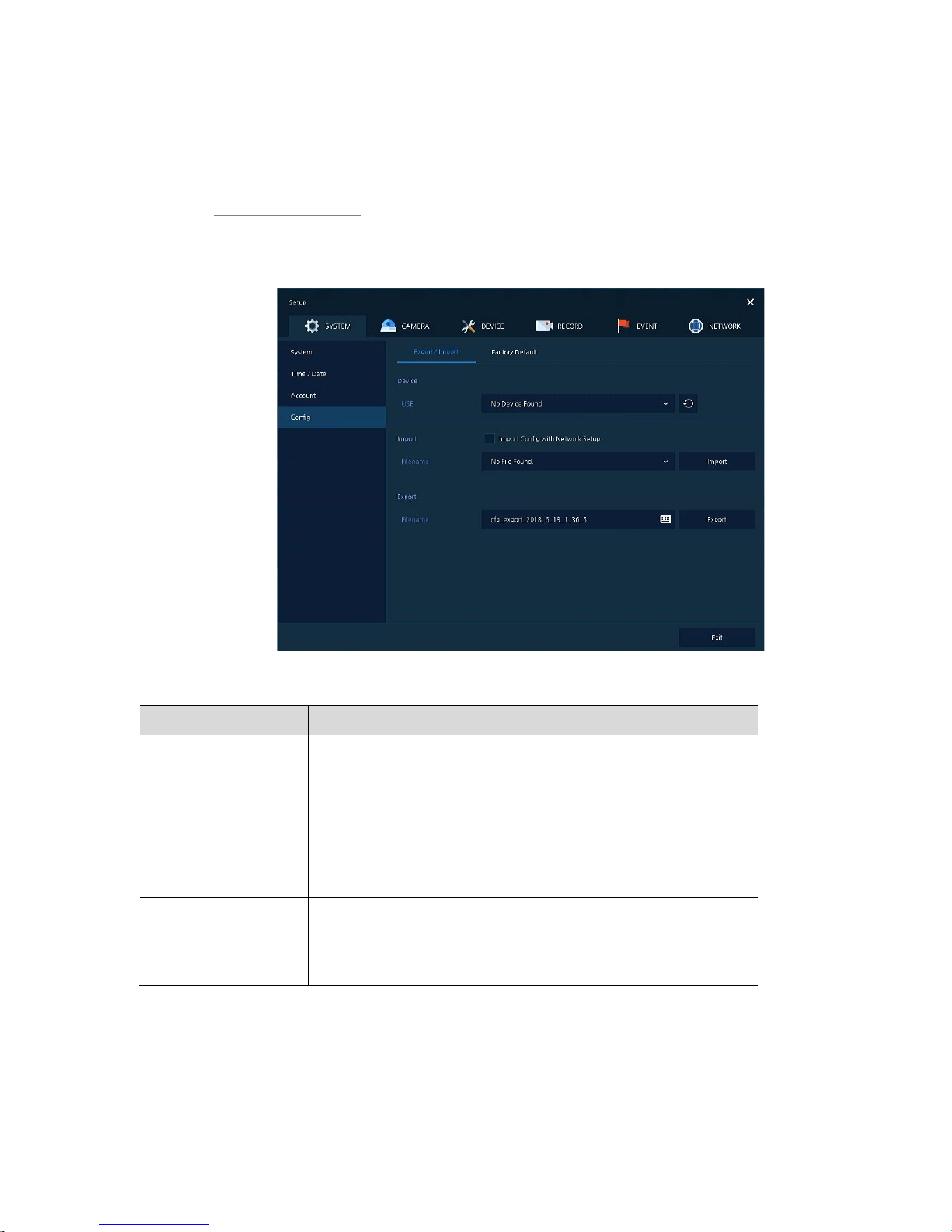
Set Export/Import and Factory Default of the system.
Config > Export/Import
Through a save medium, users may apply information set to other devices identically.
Figure 4-11 SYSTEM > Config > Export/Import
Table 4-12 SYSTEM > Config > Export/Import Item and Description
No. Name Function
1 Device Select an exterior connector with USB.
USB: Displays the USB device connected.
Refresh button: Re-recognize the device.
2 Import Apply information saved in USB to the device.
Import Config with network setup: The network setting information is
brought from the setting information.
Import button: The file in USB is brought to the desi gn ated device.
3 Export Save the set information in the USB.
Export Config with network setup: Save the information including
network setting one from the setting information to be exported.
Export button: Save the set information in the USB.
Page 42
38
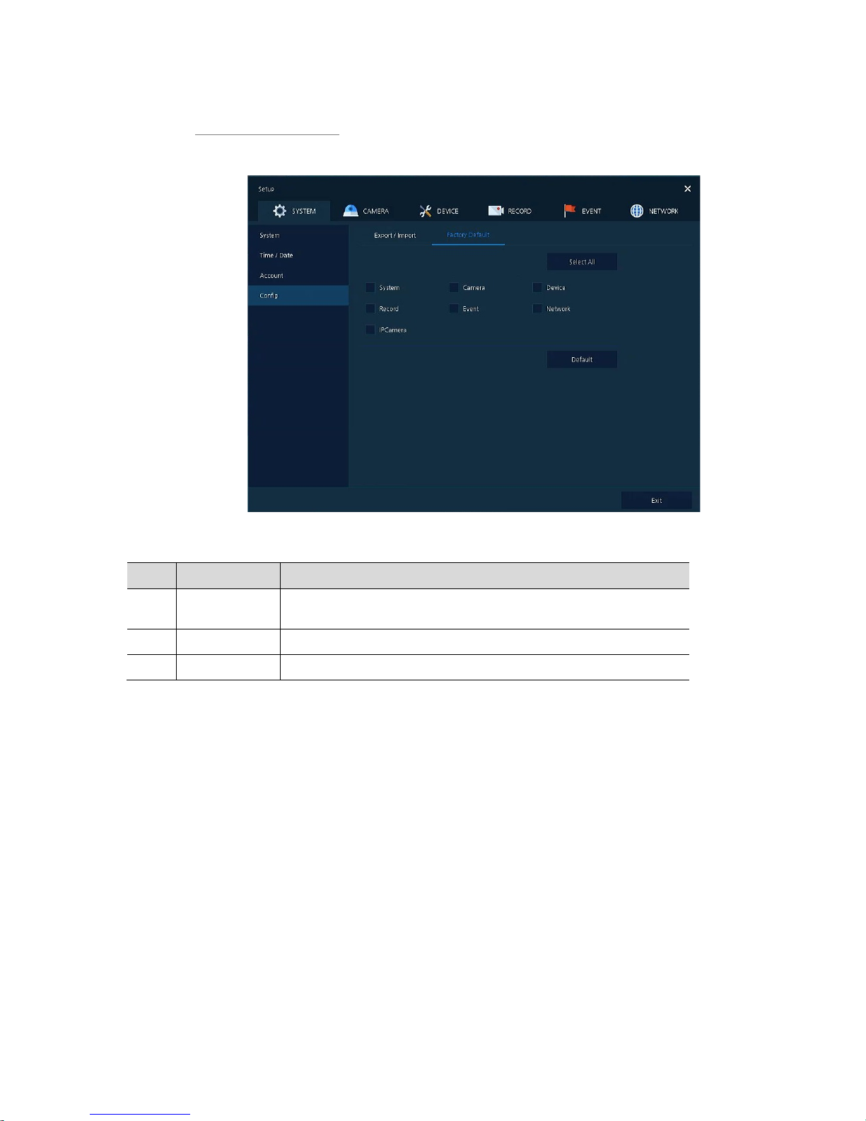
Config > Factory Default
Default the setting value of the device.
Figure 4-12 SYSTEM > Config > Factory Default
Table 4-13 SYSTEM > Config > Factory Default Item and Description
No. Name Function
1
Select All
/Unselect All
Select/deselec t all it ems to be defaulted.
2 Default Item Select/deselect related items to be defaulted.
3 Default button Default the system to the basics.
Page 43
39
4.3 CAMERA
In CAMERA section, set the camera to be connected with the device.
4.3.1 Basic
Set the fundamental functions of camera a nd audi o.
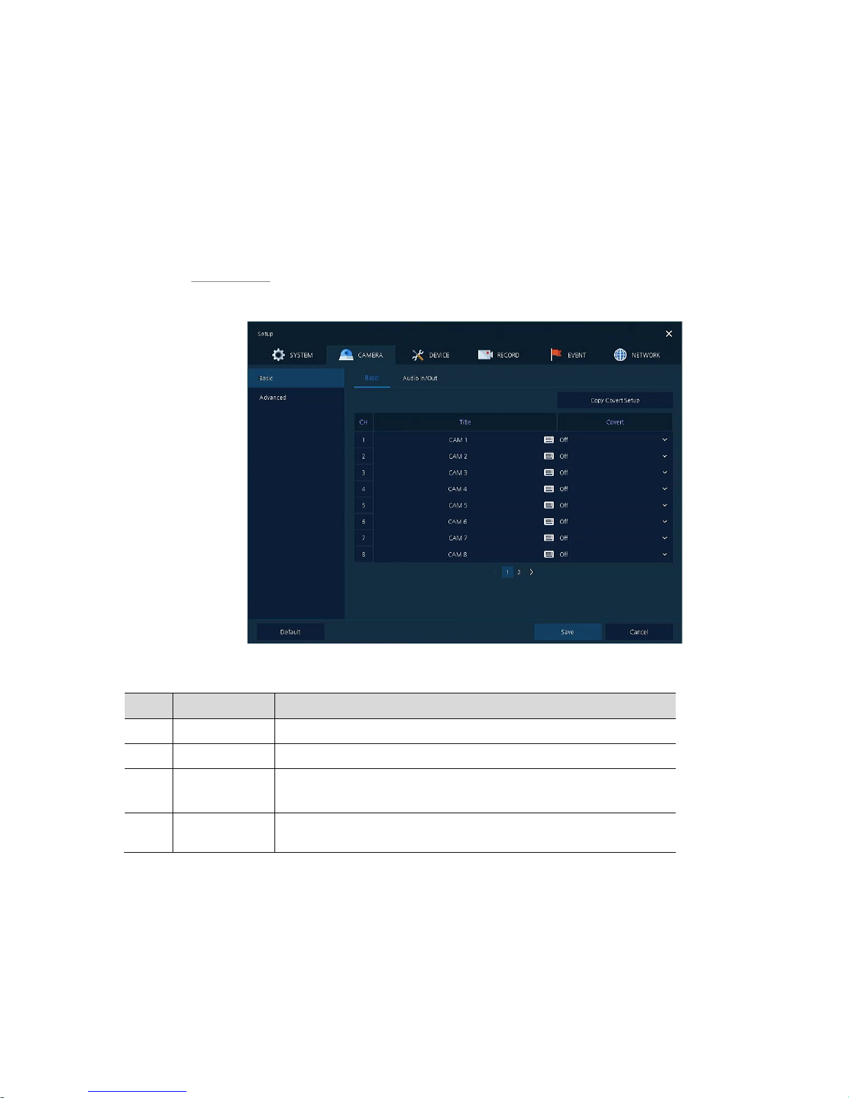
Basic > Basic
Set the basic items of camera by channels.
Figure 4-13 CAMERA > Basic > Basic
Table 4-14 CAMERA > Basic > Basic Item and Description
No. Name Function
1 CH Display the channel name.
2 Title Enter the camera name of relevant channels.
3 Covert Select images to be shown in the Live screen by channels and whether to
mark a status message or not (Off, Video Only, Video/State All).
4
Copy Covert
Setup
In Convert, set items can be duplicated to other channels.
Page 44
40
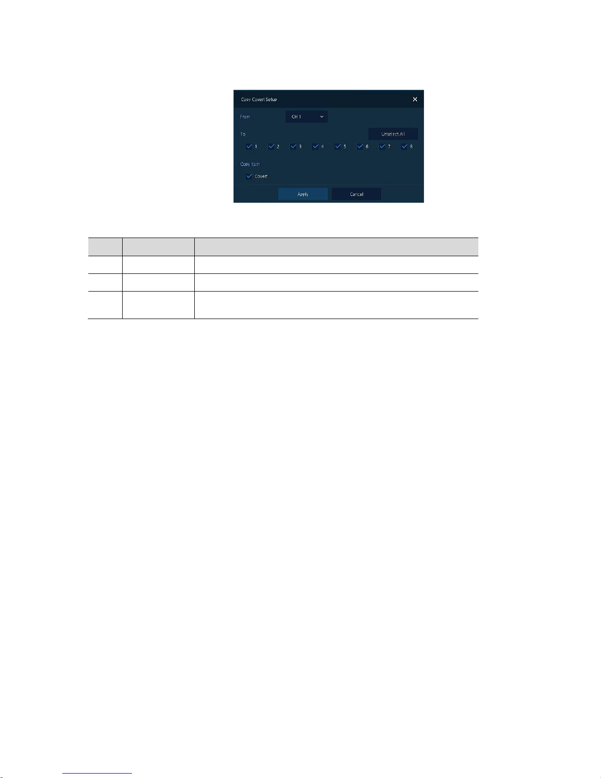
Press Copy Covert Setup button, then Copy Covert Setup screen displays.
Figure 4-14 CAMERA > Basic > Basic > Copy Covert Setup
Table 4-15 CAMERA > Basic > Basic > Copy Covert Setup Item and Description
No. Name Function
1 From Select a channel converted setting.
2 To Select a channel to be copied.
3
Select All
/Unselect All
Select/deselect all channels.
Page 45
41
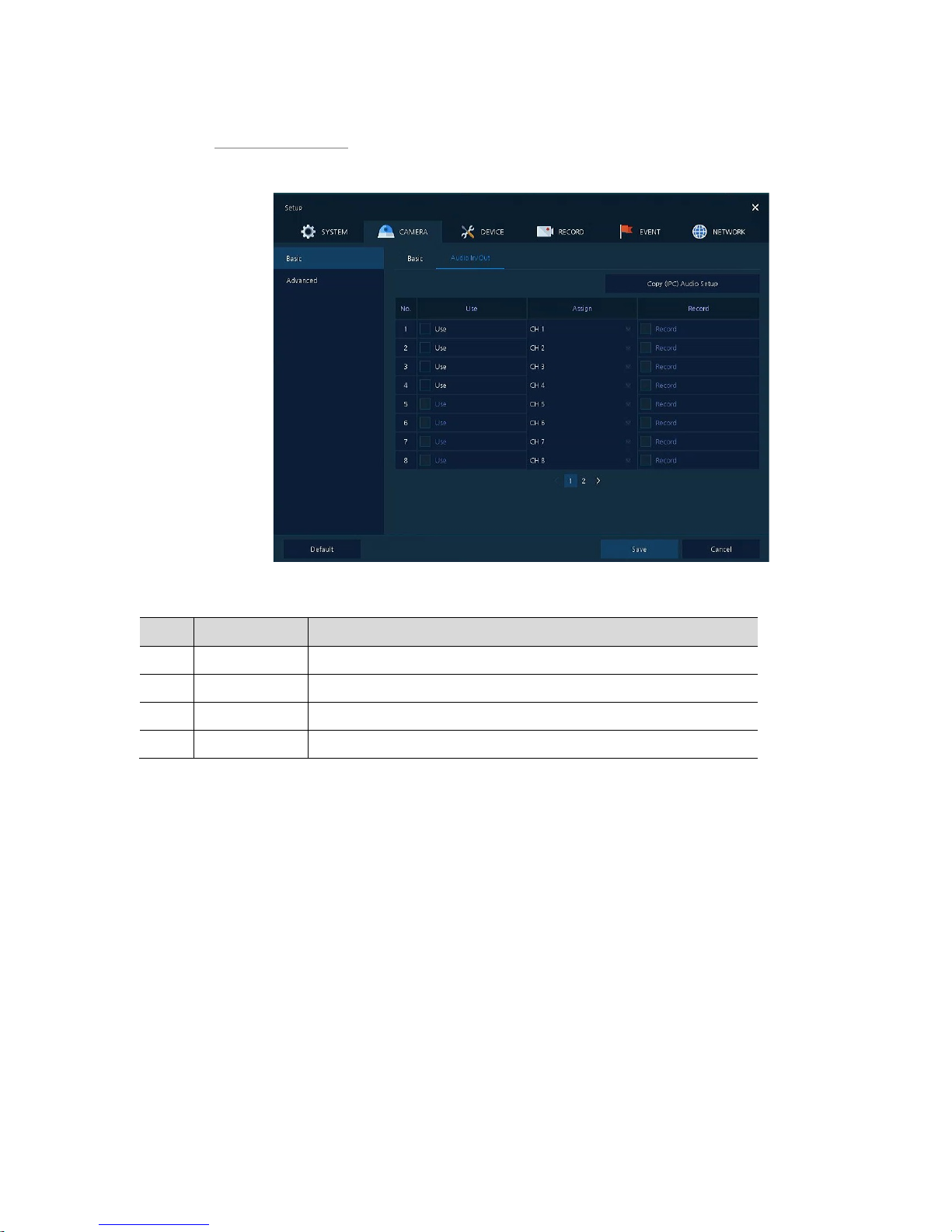
Basic > Audio In/Out
How to set audio of camera across channels
Figure 4-15 CAMERA >Basic > Audio In/Out
Table 4-16 CAMERA > Basic > Audio In/Out Item and Description
No. Name Function
1 No Display channels of audio
2 Use Select/deselect whether to use audio.
3 Assign Select channels to be assigned audio.
4 Record Select/deselect whether to save audio.
Page 46
42
4.3.2 Advanced
Set camera video, stream and privacy mask.
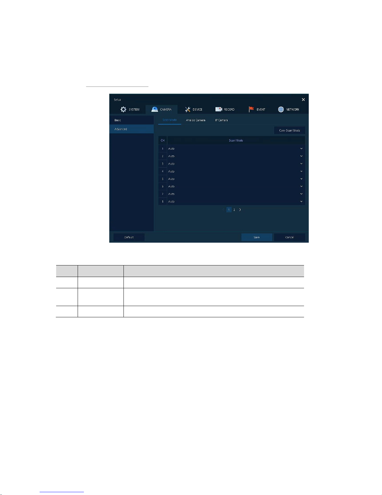
Advanced > Scan Mode
Figure 4-16 CAMERA > Advanced > Scan Mode
Table 4-17 CAMERA > Advanced > Scan Mode Item and Description
No. Name Function
1 CH Display channels.
2 Scan Mode
Automatically detects the camera input type or fixes the input video format
to the selected type (Auto, AHD, TVI).
3 Copy Scan Mode Copies the currently set scan mode settings to another channels.
Page 47
43
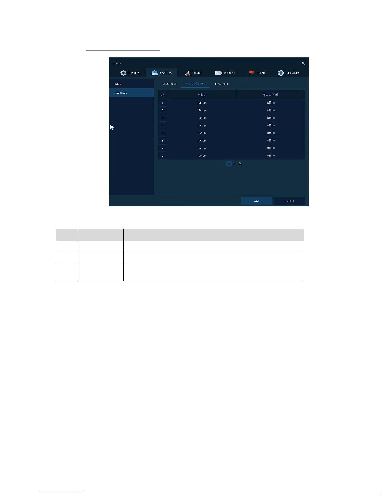
Advanced > Analog Camera
Figure 4-17 CAMERA > Advanced > Analog Camera
Table 4-18 CAMERA > Advanced > Analog Camera Item and Description
No. Name Function
1 CH Display channels.
2 Video Set brightness, contrast, and color of the camera.
3 Privacy Mask
Set the privacy field; display field numbers set in parenthesis (at most 4
setting available).
Page 48
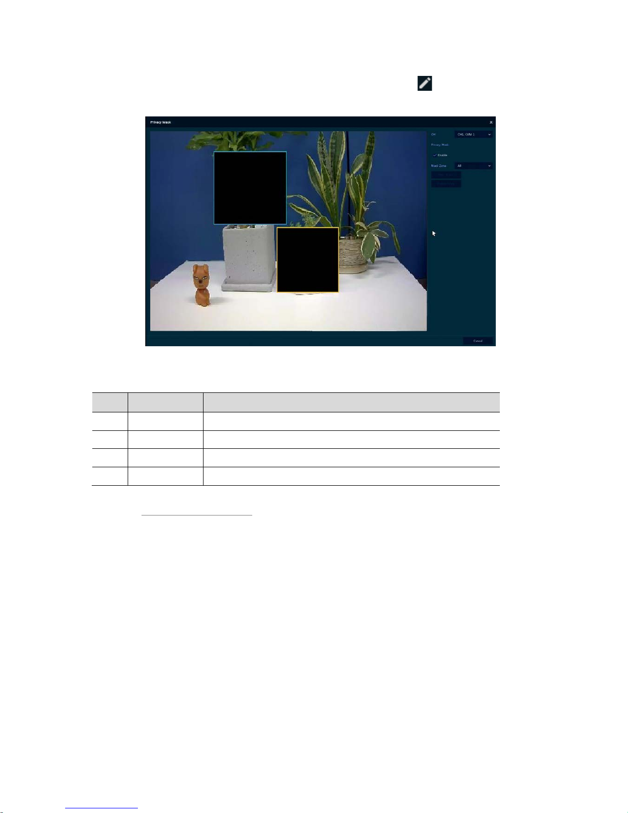
44
Locate the mouse in the Privacy Mask field, and then click Editing Icon ( ) in the right corner, then
Privacy Mask screen displays.
Figure 4-18 CAMERA > Advanced > Privacy Mask
Table 4-19 CAMERA > Advanced > Privacy Mask Item and Description
No. Name Function
1 CH Select channels to set privacy field.
2 Privacy Mask Select/deselect whether to use privacy field.
3 New Mask Select privacy field again.
4 Delete Mask Delete selected privacy field.
How to set Privacy Mask
Users might set 4 Privacy Masks, and the way to set Privacy Mask is as follows:
1
Press New Mask button. Mask Zone is automatically set as Mask1.
2
Drag the area you want in the screen with a mouse.
Revision: Select Mask No. in Mask Zone and drag the area you want in the screen with a mouse.
Deletion: Select Mask No. in Mask Zone and click Delete Mask.
3
Press Apply button to complete setting.
Page 49
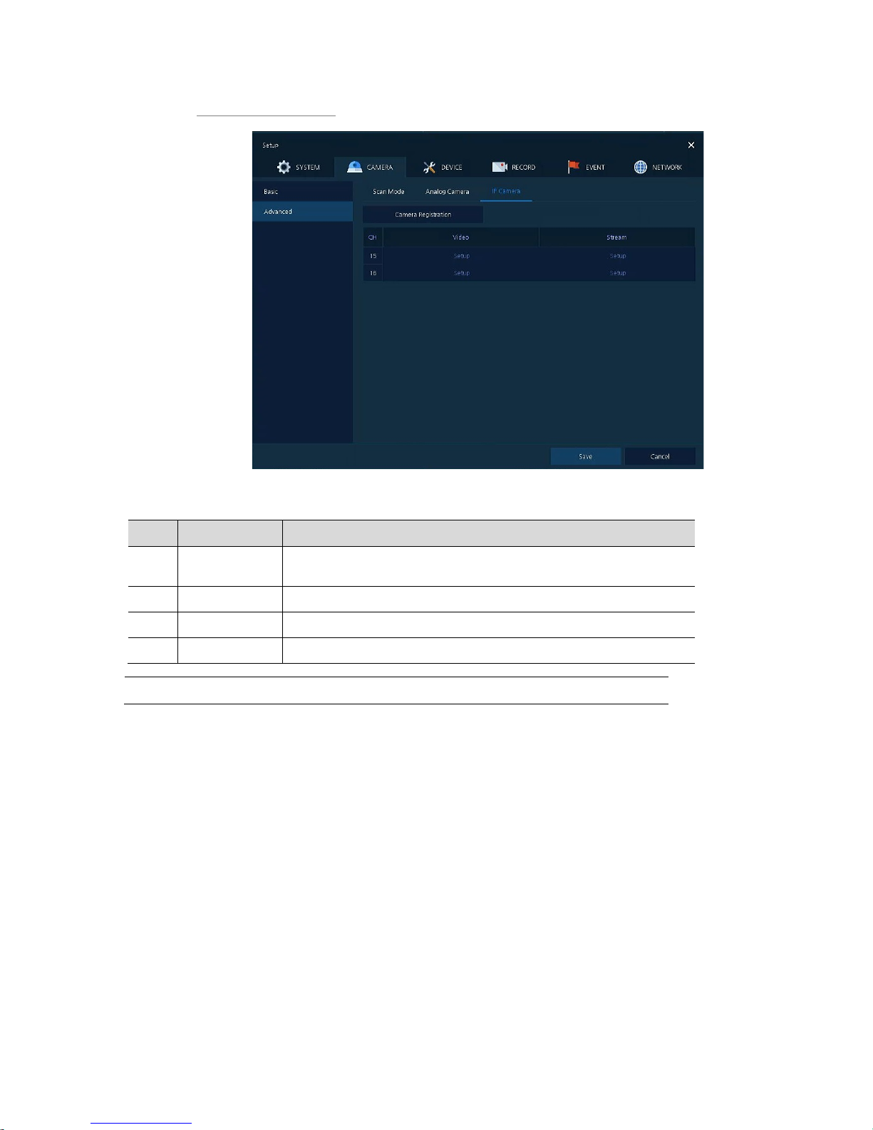
45
Advanced > IP Camera
Figure 4-19 CAMERA > Advanced > IP Camera
Table 4-20 CAMERA > Advanced > IP Camera Item and Description
No. Name Function
1
Camera
Registration
Opens a pop-up menu for IP camera registration.
1 CH Display channels.
2 Video Set brightness, contrast, and color of the camera.
3 Stream Setup camera stream such as Resolution, Framerate, Bitrate and etc.
Note
This menu will be appeared when Analog+IP cam mode is selected.
Page 50
46
4.4 DEVICE
In DEVICE, set the device to connect with the unit.
4.4.1 Display
Set matters related to a display device and live screen.
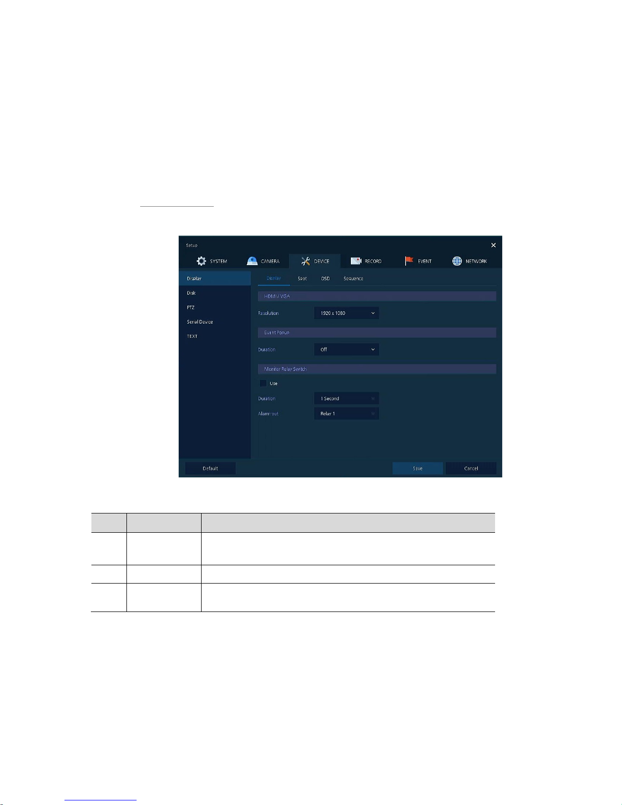
Display > Display
Set the display device.
Figure 4-20 DEVICE > Display > Display
Table 4-21 DEVICE > Display > Display Item and Description
No. Name Function
1 HDMI/VGA Select the resolution of the display device.
(1024x768, 1280x720, 1920x1080, 3840x2160).
2 Event Popup Set duration of event popup.
3
Monitor Relay
Switch
Send alarm out when screen layout changed.
Page 51
47
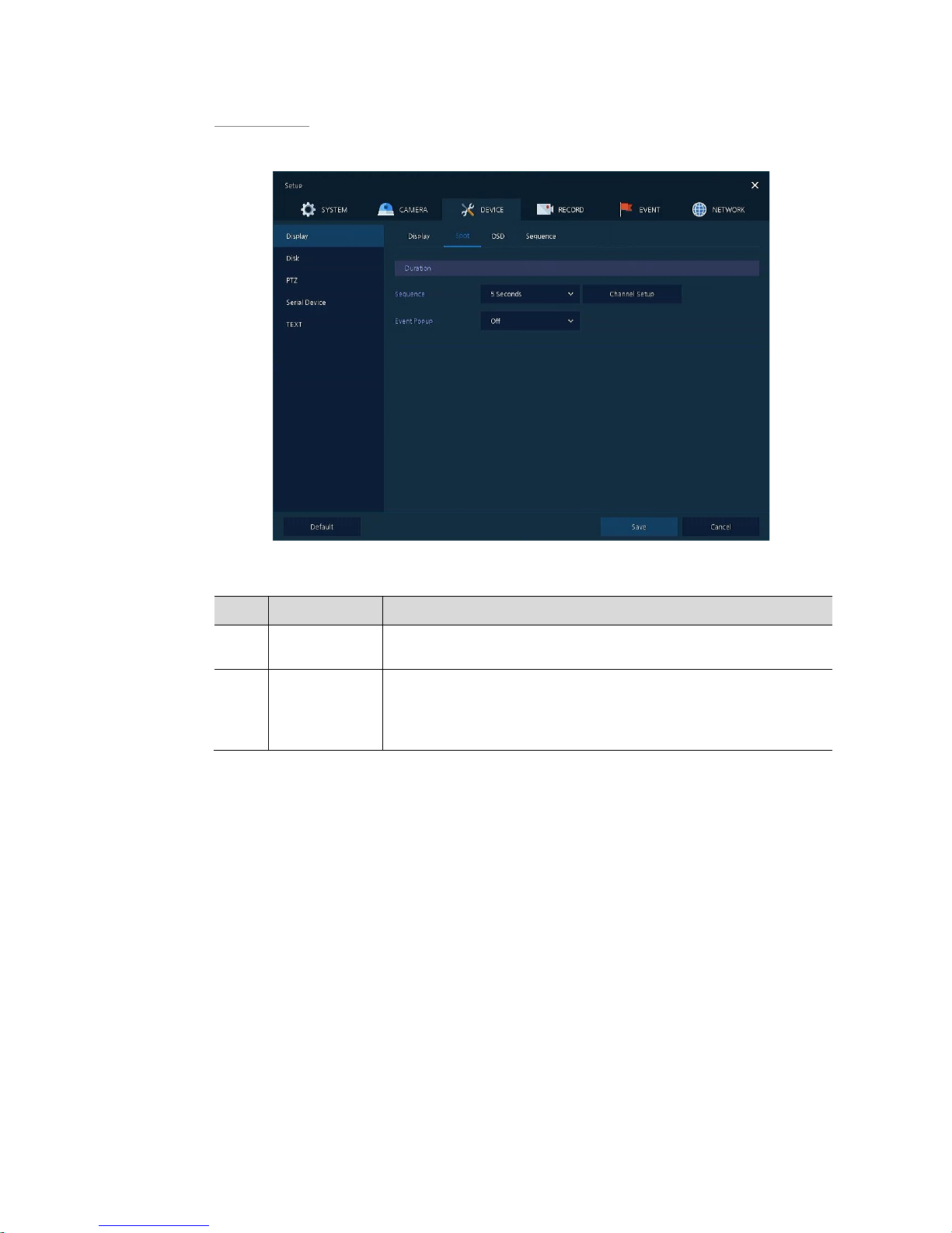
Display > Spot
Set the output of the Spot monitor.
Figure 4-21 DEVICE > Display > Spot
Table 4-22 DEVICE > Display > Spot Item and Description
No. Name Function
1 Sequence
Set the channel and dwell time (5, 10, 20, 30sec) when the Auto mode of
Spot Monitor is selected.
2 Event Popup
Sets the hold time of the full screen image of the channel where the event
occurred (Off, 5, 10, 20, 30sec, Continuous).
If multiple channels have an event at the same time, the event channel is
shown as a spilt screen.
Page 52
48
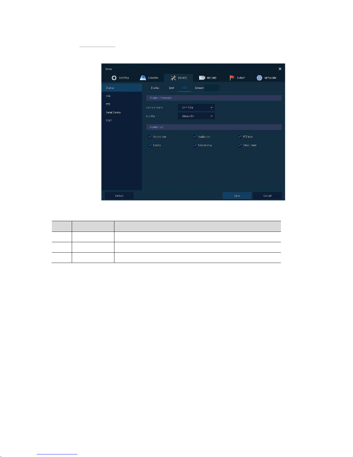
Display > OSD
Set the OSD of the display device.
Figure 4-22 DEVICE > Display > OSD
Table 4-23 DEVICE > Display > OSD Item and Description
No. Name Function
1 Camera Name Select the way to display camera in live screen (Off, CH+Title, CH).
2 Live Bar Select the way to display the live bar (Always On, Auto Hide).
3 Display Icon Select/deselect icons to display in the live screen.
Page 53
49
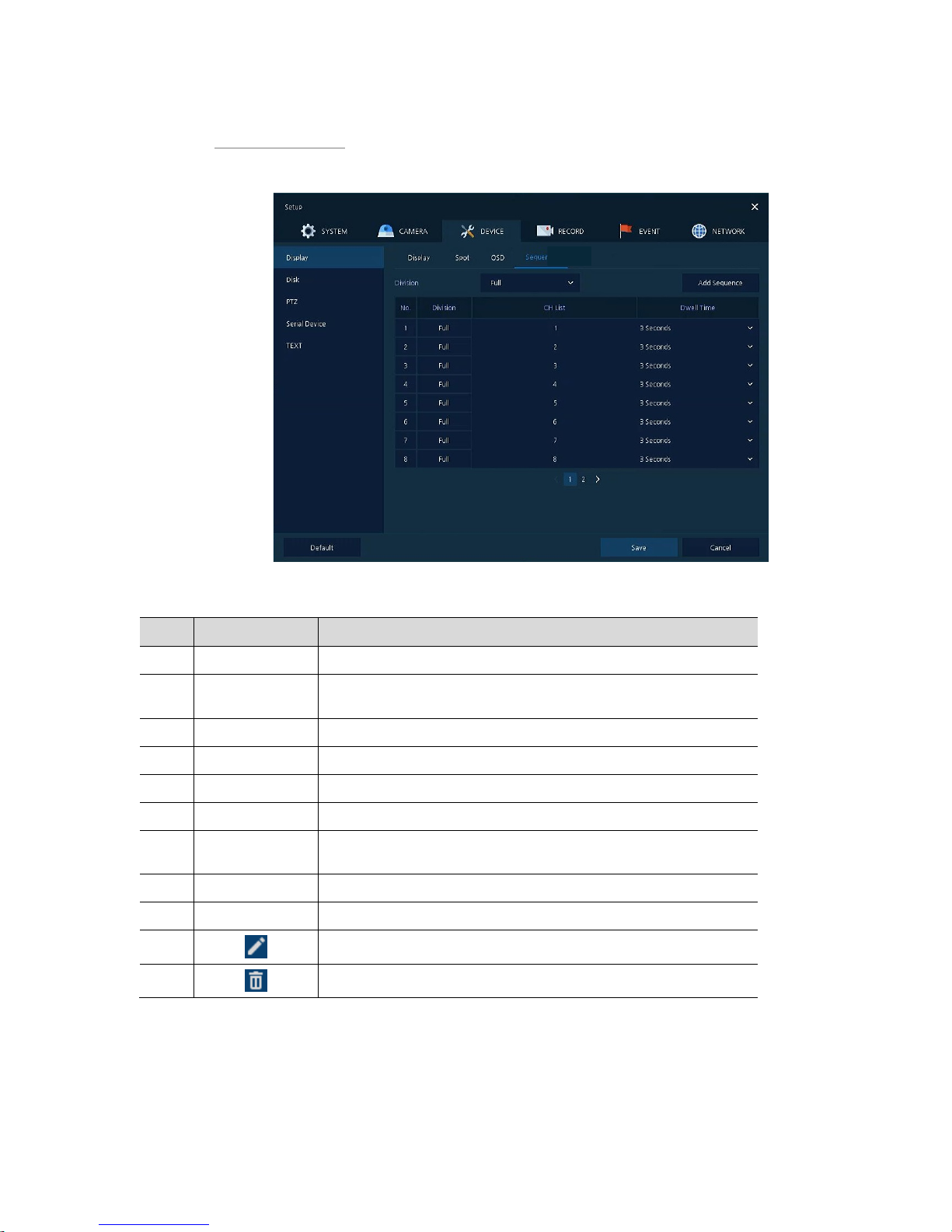
Display > Sequence
How to set the play sequence of live screen
Figure 4-23 DEVICE > Display > Sequence
Table 4-24 DEVICE > Display > Sequence Item and Description
No. Name Function
1 Quad Sequence Set to convert automatically as 4-partition screen on the time basis.
2 Division
Select screen partition mode to be marked in the below table (All, Full,
and Quad).
3 Sequence List Display the sequence list based on division selected value.
4 Add Sequence Add items to be included in the play sequence.
NO Automatically controvert screens in number order.
Division Displays as full, 2X2 (Quad).
CH LIST
Set automatic conversion CHs. In case of choosing CH3 in No. 1, CH3 is
shown in advance.
Dwell Time Set the remaining time for automatic conversion (3 sec~30 sec).
Default Reverse to changed set value in default.
Revise the list.
Delete the list.
Page 54
50
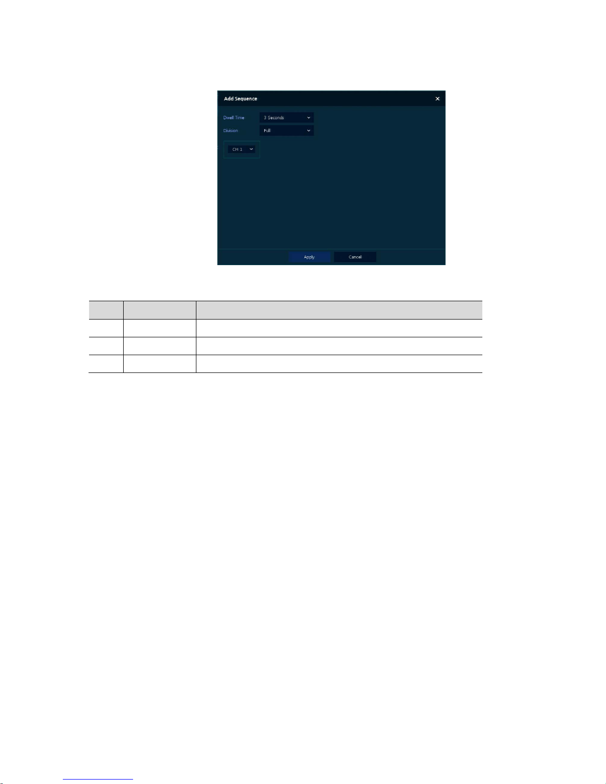
Clicking Add Sequence displays Add Sequence screen.
Figure 4-24 DEVICE > Display > Sequence > Add Sequence
Table 4-25 DEVICE > Display > Sequence > Add Sequence Item and Description
No. Name Function
1 Dwell Time Select time to play (3 sec, 5 sec, 10 sec, 15 sec, and 30 sec).
2 Division Select the partition screen to play (Full, Quad).
3 Channel Selection Select channels to play.
Page 55
51
4.4.2 Disk
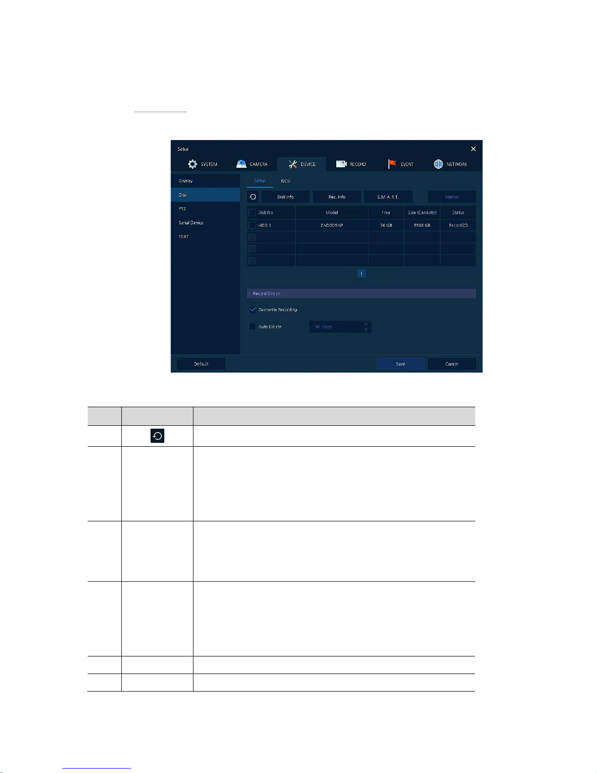
Disk > Setup
The way to set the disk
Figure 4-25 DEVICE > Disk > Setup
Table 4-26 DEVICE > Disk > Setup Item and Description
No. Name Function
1
Refresh disk information.
2 Disk Info Display the basic disk information in disc list.
Model: disk model name
Free: disk capacity to save
Size (Capacity): total disk capacity
Status: disk status
3 Rec. Info Display saved disk information in disc list.
Start Recording Time: starting time for saving information in the disk
End Recording Time: ending time to stop saving information in the disk
Status: disk status
4 S.M.A.R.T. Display S.M.A.R.T. information in disc list.
Model: disk model name
Temp.: disk temperature
Alive Time: running time after turning on the disk
S.M.A.R.T.: a presenter of disk’s malfunction
5 Disk List Display the disk list select/deselect disc to be formatted.
6 Format Format the disk selected.
Page 56
52
No. Name Function
7
Overwrite
Recording
Select/deselect to rewrite new data on the existing disk in case of
insufficient savi n g space remained.
8 Auto Delete
Select/deselect to use the function to delete saved data automatically (1365 days).
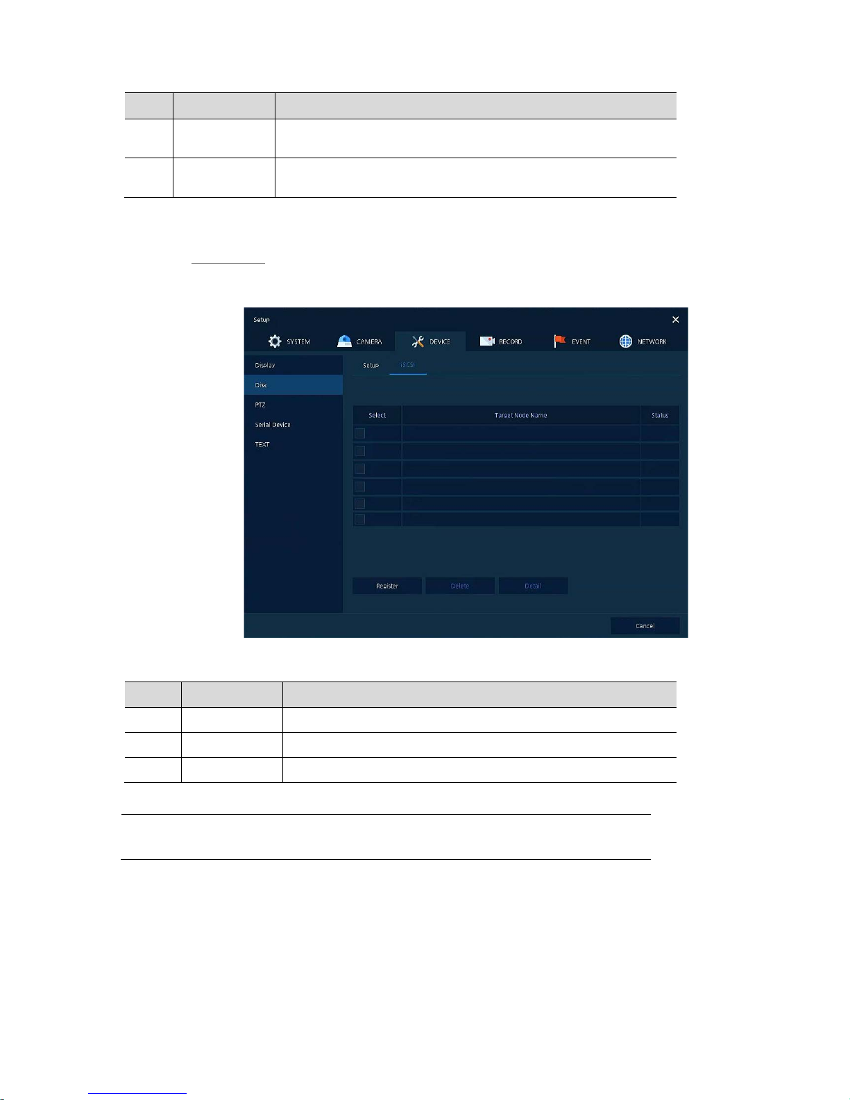
Disk > iSCSI
The way to set the iSCSI
. Figure 4-26 DEVICE > Disk > iSCSI
Table 4-27 DEVICE > Disk > iSCSI Item and Description
No. Name Function
1 Register Opens a pop-up menu for iSCSI registration.
2 Delete Delete registered iSCSI storage.
3 Detail Display selected iSCSI IP address and port number.
Note
Recorder support Max. 6 volumes(Target Node).
Each volume supports Max. 16TB.
Page 57
53
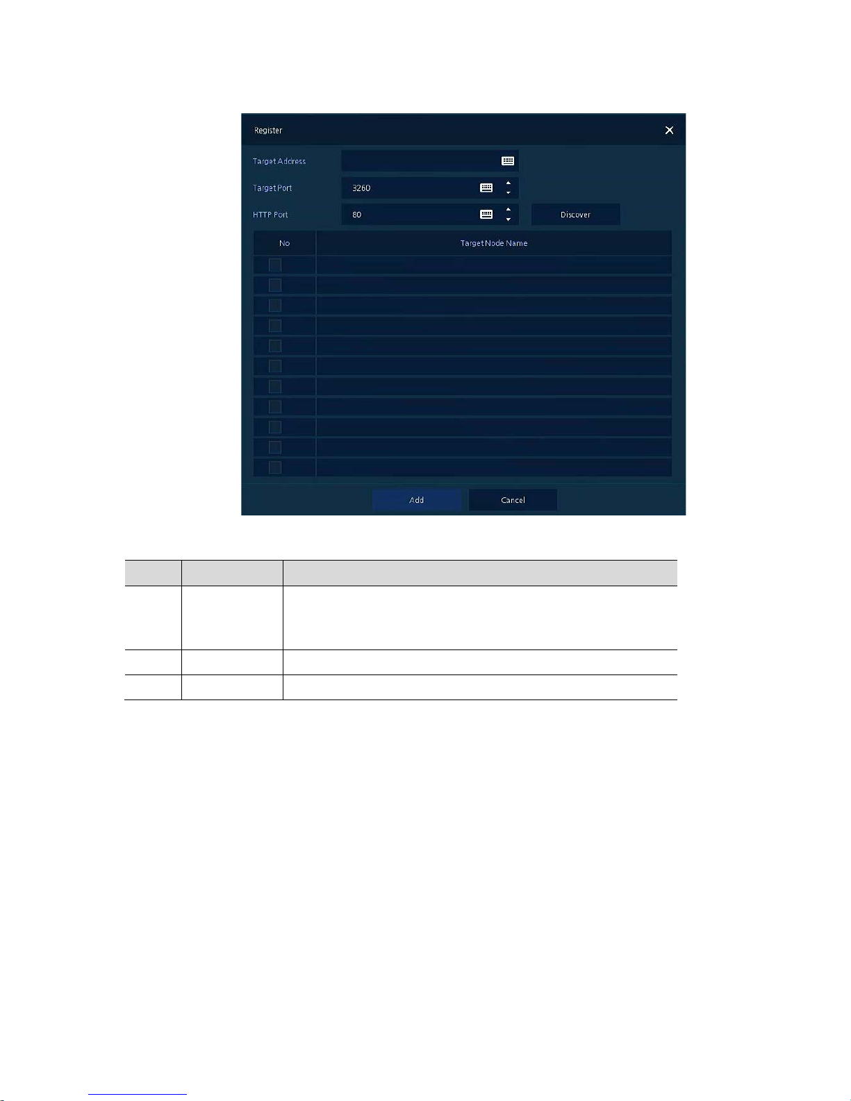
Clicking Register displays iSCSI Register screen.
Figure 4-27 DEVICE > Disk > iSCSI > Register
Table 4-28 DEVICE > Disk > iSCSI > Register Item and Description
No. Name Function
1 Target Address
Target Port
HTTP Port
Input IP address and port for iSCSI.
2 Discover Click to search iSCSI storage.
3 Add Click to register the discovered iSCSI storage.
Page 58
54
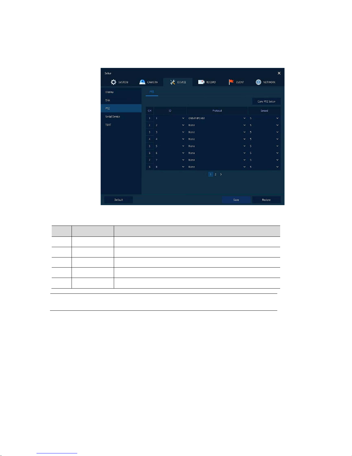
4.4.3 PTZ > PTZ
To use PTZ Function of the device, users need to match ID, protocol, and speed with each camera.
Figure 4-28 DEVICE > PTZ > PTZ
Table 4-29 DEVICE > PTZ > PTZ Item and Description
No. Name Function
1 Copy PTZ Setup Apply setting history to all or selected channels in the same way.
2 CH Display channels.
3 ID Select camera ID connected to relevant channels (1-255).
4 Protocol Select protocol of camera connected to relevant channels.
5 Speed Select pan-tilt of camera connected to relevant channels (1-5).
Note
For more information about camera ID, protocol information, and details, see
Instruction of relevant PTZ function camera.
Page 59
55
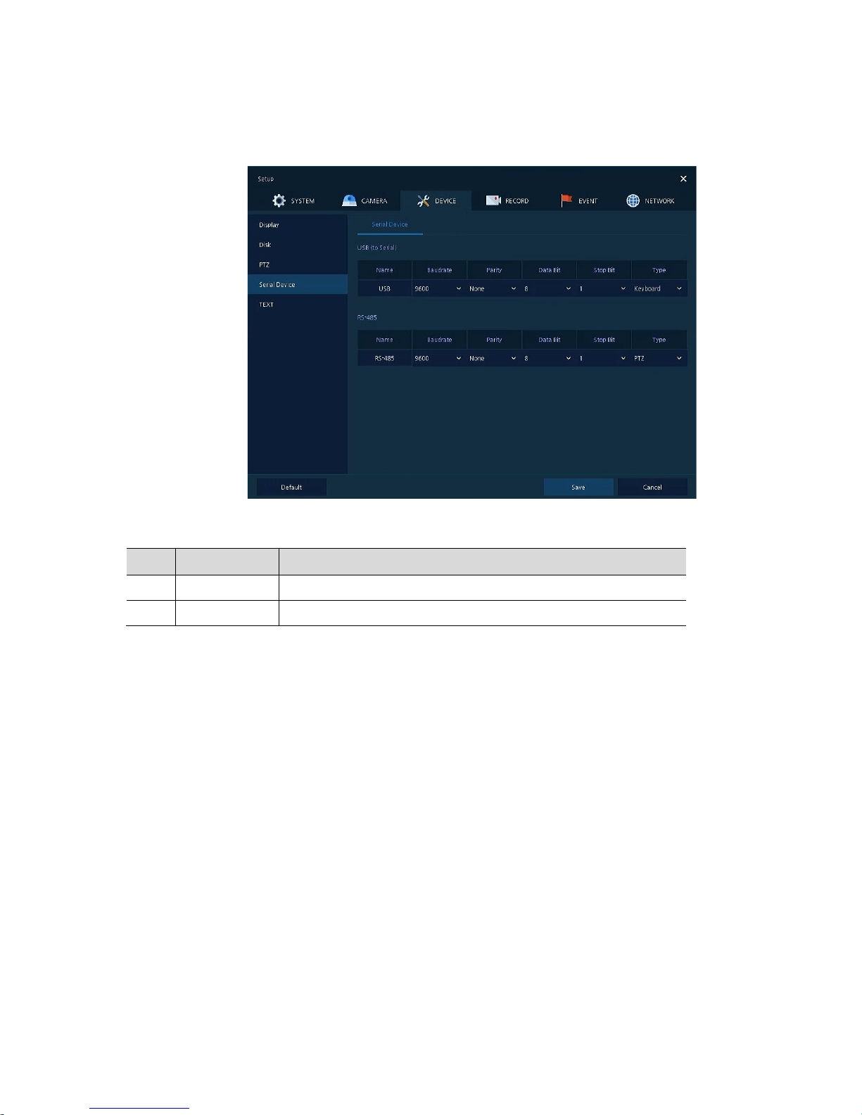
4.4.4 Serial Device > Serial Device
Users need to set Serial Device to connect PTZ camera, USB device with the unit.
Figure 4-29 DEVICE > Serial Device > Serial Device
Table 4-30 DEVICE > Serial Device > Serial Device Item and Description
No. Name Function
1 USB (to Serial) Set communication transmission value of USB device.
2 RS-485 Set communication transmission value of RS-485 connector.
Page 60
56
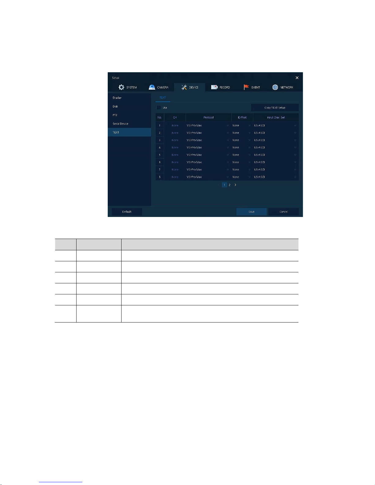
4.4.5 TEXT > TEXT
Set the input device such as ATM or POS, etc.
Figure 4-30 DEVICE > TEXT > TEXT
Table 4-31 DEVICE > TEXT > TEXT Item and Description
No. Name Function
1 Use Select/deselect whether to use text function.
2 CH Select camera channels to connect with the text input device.
3 Protocol Select protocol to correspond with the text input device.
4 ID. Port Select ID and port no. to correspond with the text input device.
5 Input Char. Set Select a character format of the text input device.
6
Copy to TEXT
Setup
As for connecting multiple units, duplicate set value to others.
Page 61
57
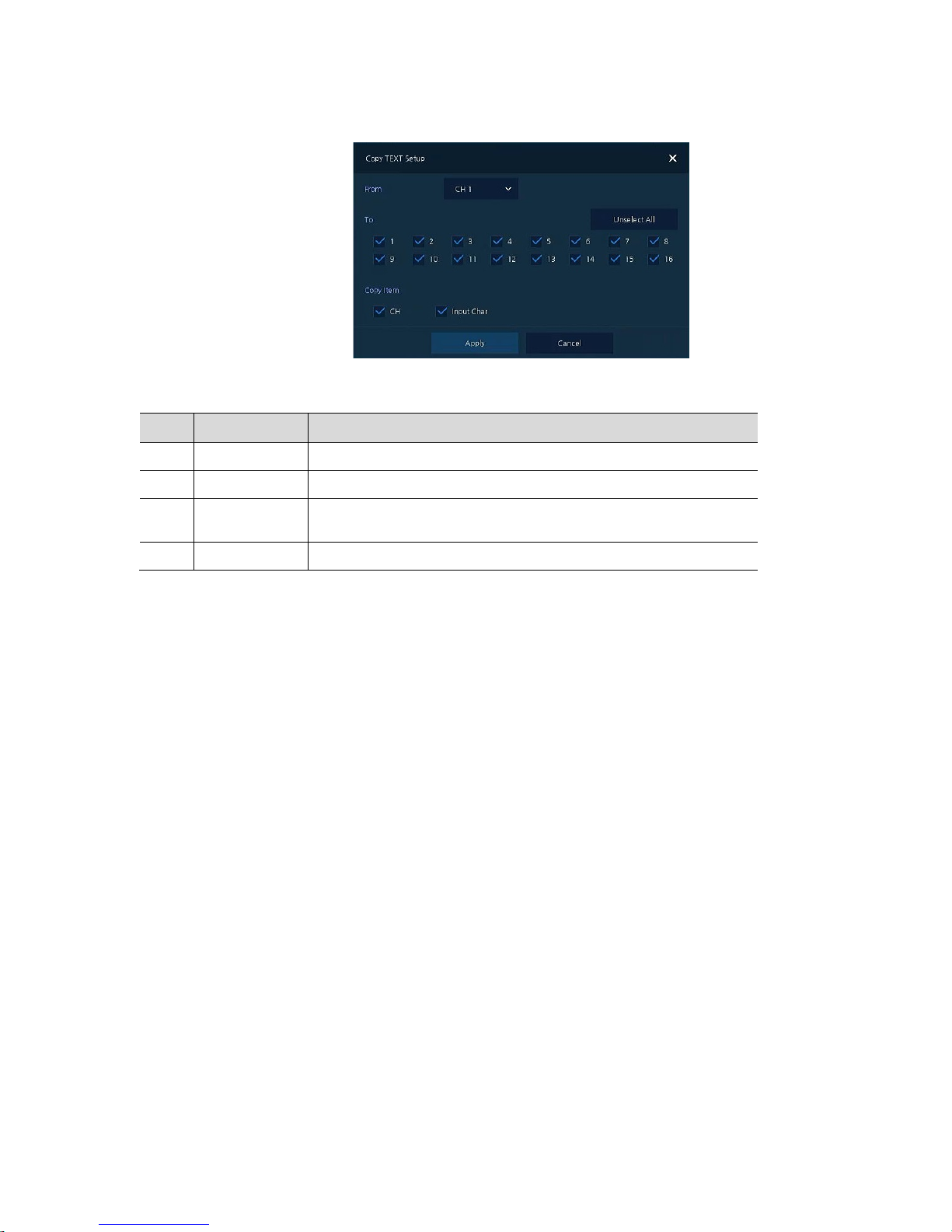
Press Copy to TEXT Setup button, then Copy to TEXT Setup screen displays.
Figure 4-31 DEVICE > TEXT > TEXT > Copy to TEXT Setup
Table 4-32 DEVICE > TEXT > TEXT > Copy to TEXT Setup Item and Description
No. Name Function
1 From Select channels set.
2 To Select the device to be copied.
3
Select All
/Unselect All
Select/deselect all channels.
4 Copy Item Select/deselect items to be copied.
Page 62
58
4.5 RECORD
In RECORD, users may set matters related to recording.
4.5.1 Schedule
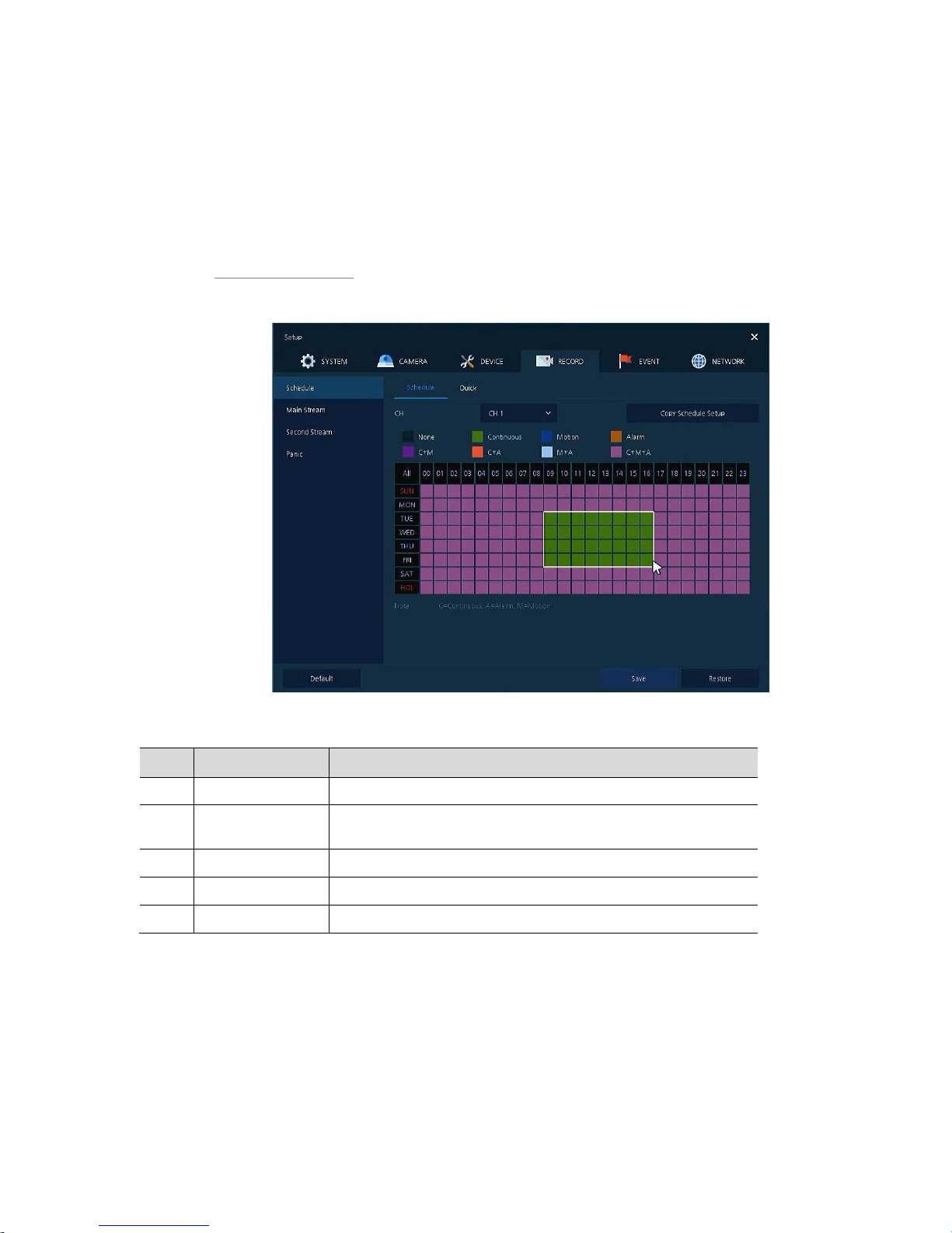
Schedule > Schedule
Recording types can be set across channels and time.
Figure 4-32 RECORD > Schedule > Schedule
Table 4-33 RECORD > Schedule > Schedule Item and Description
No. Name Function
1 CH Select channels to set schedules.
2
Schedule Type
Selection
Select the types of schedules.
3 Schedule Table Display the schedule users set.
4 Drag Field Display the area dragged with a mouse.
5 Copy Schedule Setup Copy set recording schedule to other channels.
Page 63
59
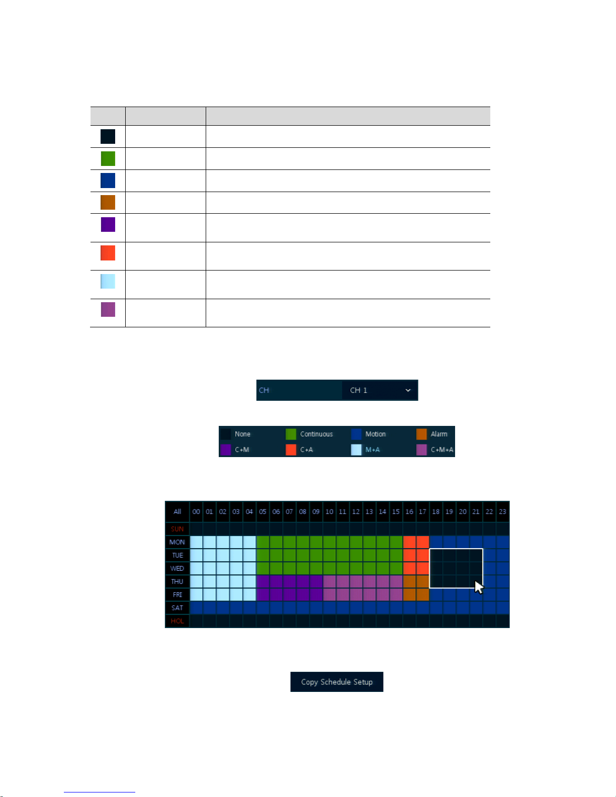
The function of each scheduling type involve s:
Table 4-34 Function of each scheduling type
Color Scheduling type Function
None Do not record.
Continuous Record on consecutive mode when time set.
Motion
Record on event recording mode when motion sensitive event occurs.
Alarm Record on event recording mode when alarm occurs.
C+M
Record on event recording mode when motion sensitive event occurs
during consecutive mode recording.
C+A
Record on event recording mode when alarm occurs during consecutive
mode recording.
M+A
Record on event recording mode when only alarm and motion sensitive
event occur.
C+M+A
Record on event recording mode when only alarm and motion sensitive
event occur during consecutive mode recording.
The way to schedule recording across channels.
1
Select channels to schedule.
2
Select items in scheduling types.
3
Position the mouse to the schedule table.
4
Drag the area to be scheduled with a mouse.
5
Selected field is presented as scheduling type colors.
6
Click Copy Schedule Setup if you want to copy the schedule to other channels.
Page 64
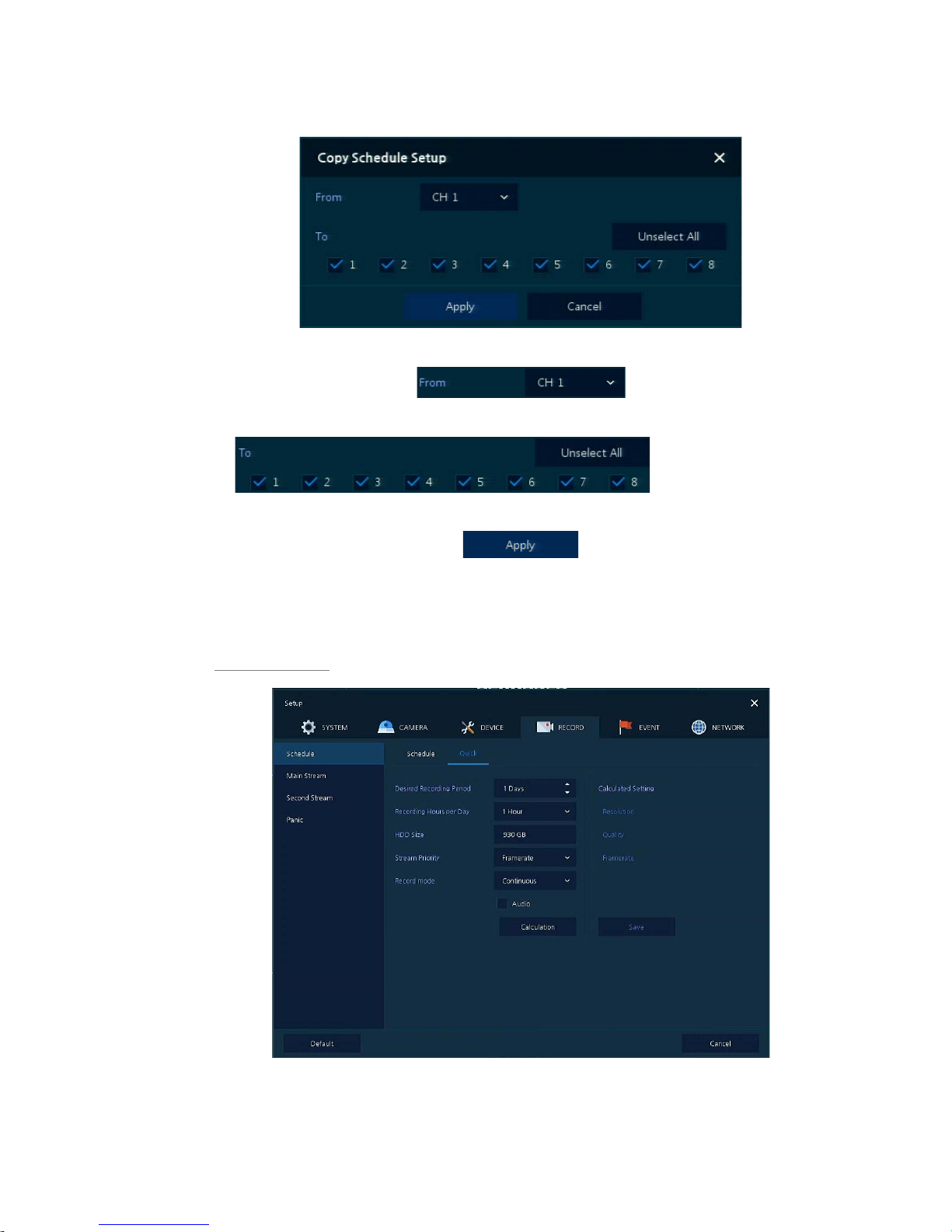
60
7
Copy Schedule Setup screen displays.
8
Select channels to be copied.
9
Select channels to apply copied content.
10
Copy the schedule by pressing Apply.
11
Press Save to save the schedule.
Schedule > Quick
Figure 4-33 RECORD > Schedule > Quick
Page 65

61
Table 4-35 RECORD > Schedule > Quick Item and Description
No. Name Function
1
Desired Recording
Period
Select desired recor di n g peri od.
2
Recording Hours per
Day
Select recording hours per day.
3 HDD Size It is automatically displayed.
4 Stream Priority Select Framerate or Resolution.
5 Recording mode Select recording mode as Continuous or Event.
6 Audio Enable if audio is recorded.
7 Calculation
User can see recommended resolution and frame rate to meet recording
period.
Page 66
62
4.5.2 Main Stream
To set the image resolution when event occurs across channels or general recording is in process.
Main Stream > Analog Camera
To set the image quality and resolution of Main Stream
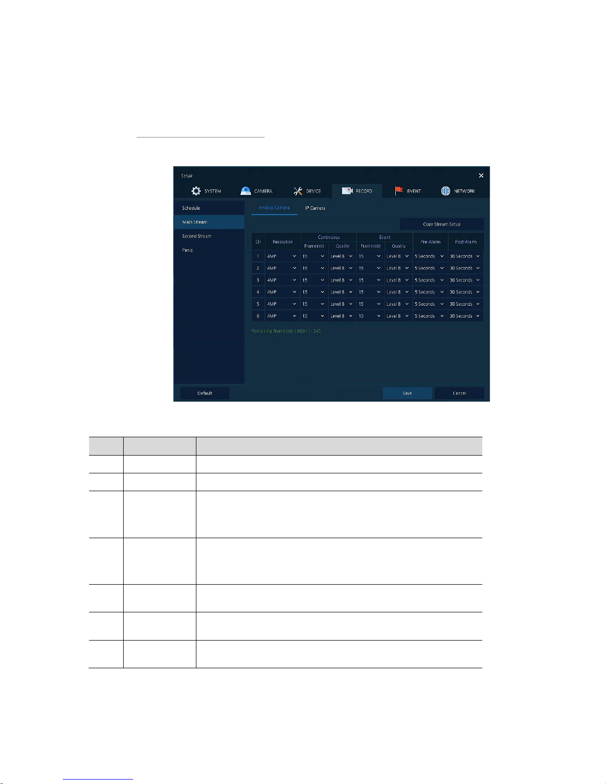
Figure 4-34 RECORD > Stream > Main Stream
Table 4-36 RECORD > Stream > Main Stream Item and Description
No. Name Function
1 CH Display channels.
2 Resolution Set the resolution of video clips (4MP, 1080P , 720P, and 960H).
3 Continuous Select recording FPS and image quality in consecutive recording.
Frame Rate: recording FPS selection (1-30)
Quality: recording image quality selection (Level 1-8)
4 Event Select recording FPS and image quality in event recording.
Frame Rate: recording FPS selection (1-30)
Quality: recording image quality selection (Level 1-8)
5 Pre-Alarm
Start recording before set time, if event occurs (null, 1 sec, 2 sec, 3 sec, 4
sec, and 5 sec).
6 Post-Alarm
Recording after set time until event ends (null, 5 sec, 10 sec, 30 sec, 1 min,
5 min, and 10 min).
7
Copy Stream
Setup
Copy main recording image set value to other channels.
Page 67
63
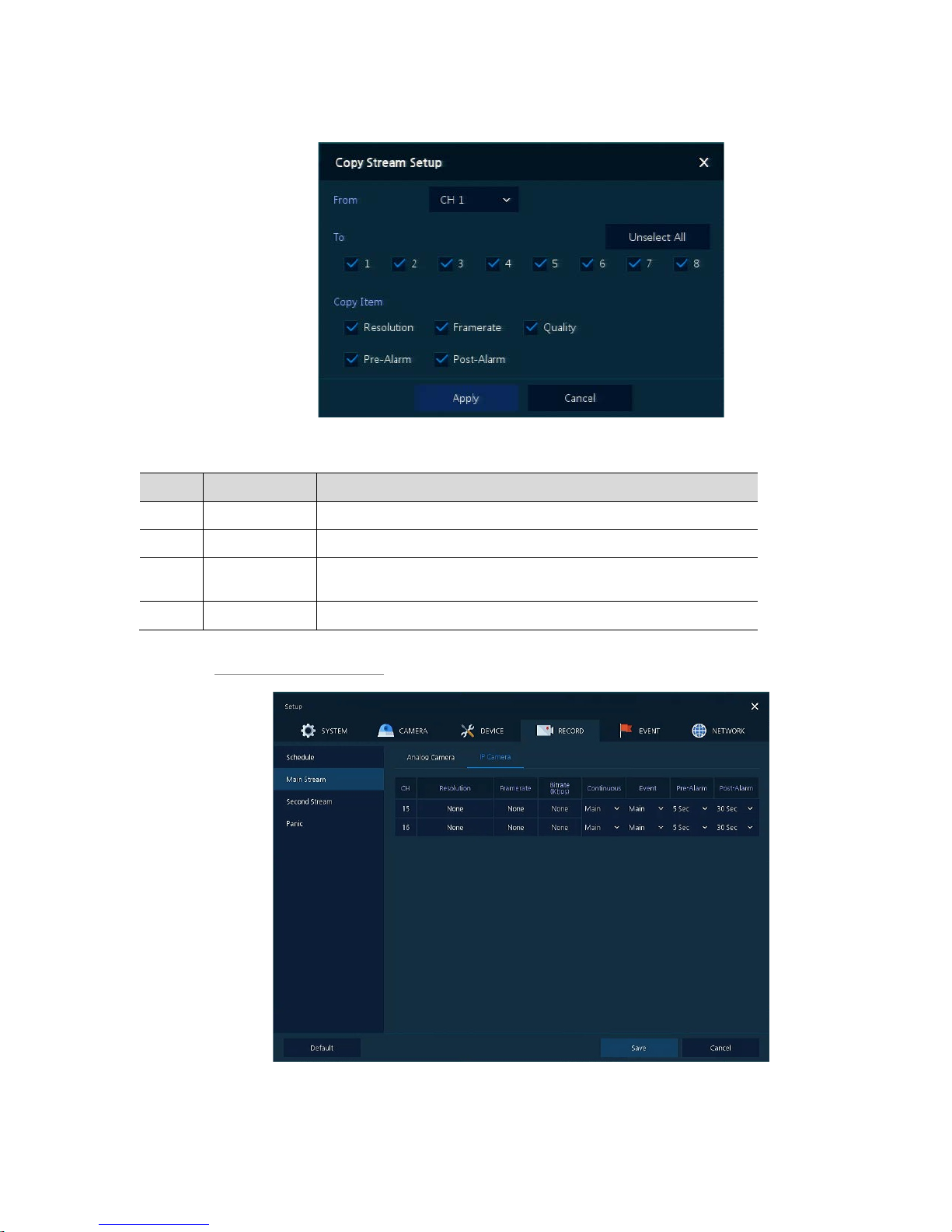
Clicking Copy Stream Setup opens Copy Stream Setup.
Figure 4-35 RECORD > Stream > Main Stream > Copy Stream Setup
Table 4-37 RECORD > Stream > Main Stream > Copy Stream Setup Item and Description
No. Name Function
1 From Select the channel set.
2 To Select the device to be copied.
3
Select All
/Unselect All
Select/deselect all channels.
4 Copy Item Select/deselect items to be copied.
Main Stream > IP Camera
Figure 4-36 RECORD > Main Stream > IP Camera
Page 68

64
Table 4-38 RECORD > Main Stream > IP Camera Item and Description
No. Name Function
1 CH Display channels.
2 Resolution
Framerate
Bitrate
Show camera main stream setup status.
3 Continuous Select recording stream in case of Continuous mode.
4 Event Select recording stream in case of Event mode.
5 Pre-Alarm
Start recording before set time, if event occurs (null, 1 sec, 2 sec, 3 sec, 4
sec, and 5 sec).
6 Post-Alarm
Recording after set time until event ends (null, 5 sec, 10 sec, 30 sec, 1 min,
5 min, and 10 min).
Note
This menu will be appeared when Analog+IP cam mode is selected.
Page 69
65
4.5.4 Second Stream
Second Stream > Analog Camera
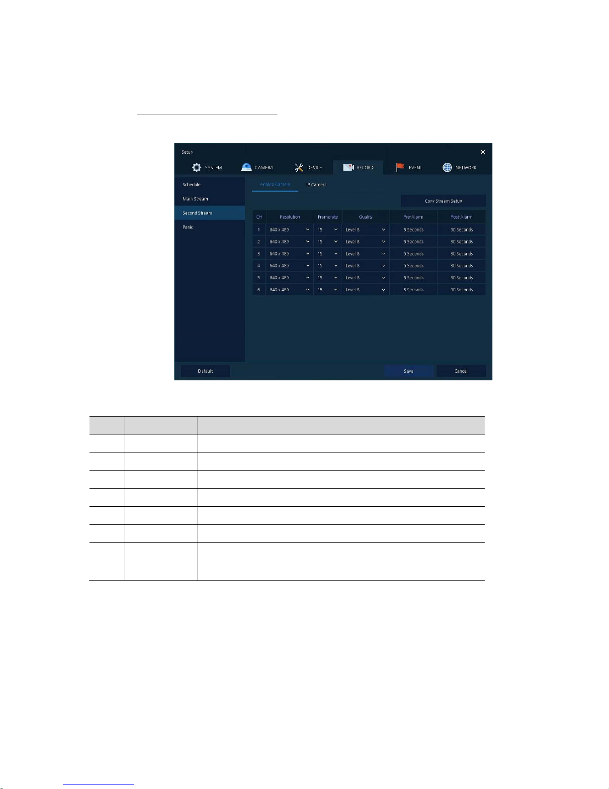
To set the image quality and resolution of Second Stream
Figure 4-37 RECORD > Stream > Second Stream
Table 4-39 RECORD > Stream > Second Stream Item and Description
No. Name Function
1 CH Display channels.
2 Resolution Set the resolution of video clips (640X480).
3 Frame Rate Select recording FPS (1-30).
4 Quality Select image quality (Level 1-8).
5 Pre-Alarm Start recording before set time, if event occurs.
6 Post-Alarm Recording after set time until event ends.
7
Copy Stream
Setup
Copy main recording image set value to other channels. For more
information about set value copy, see section “4.5.2 Stream > Main Stream
in Main Stream.”
Page 70
66
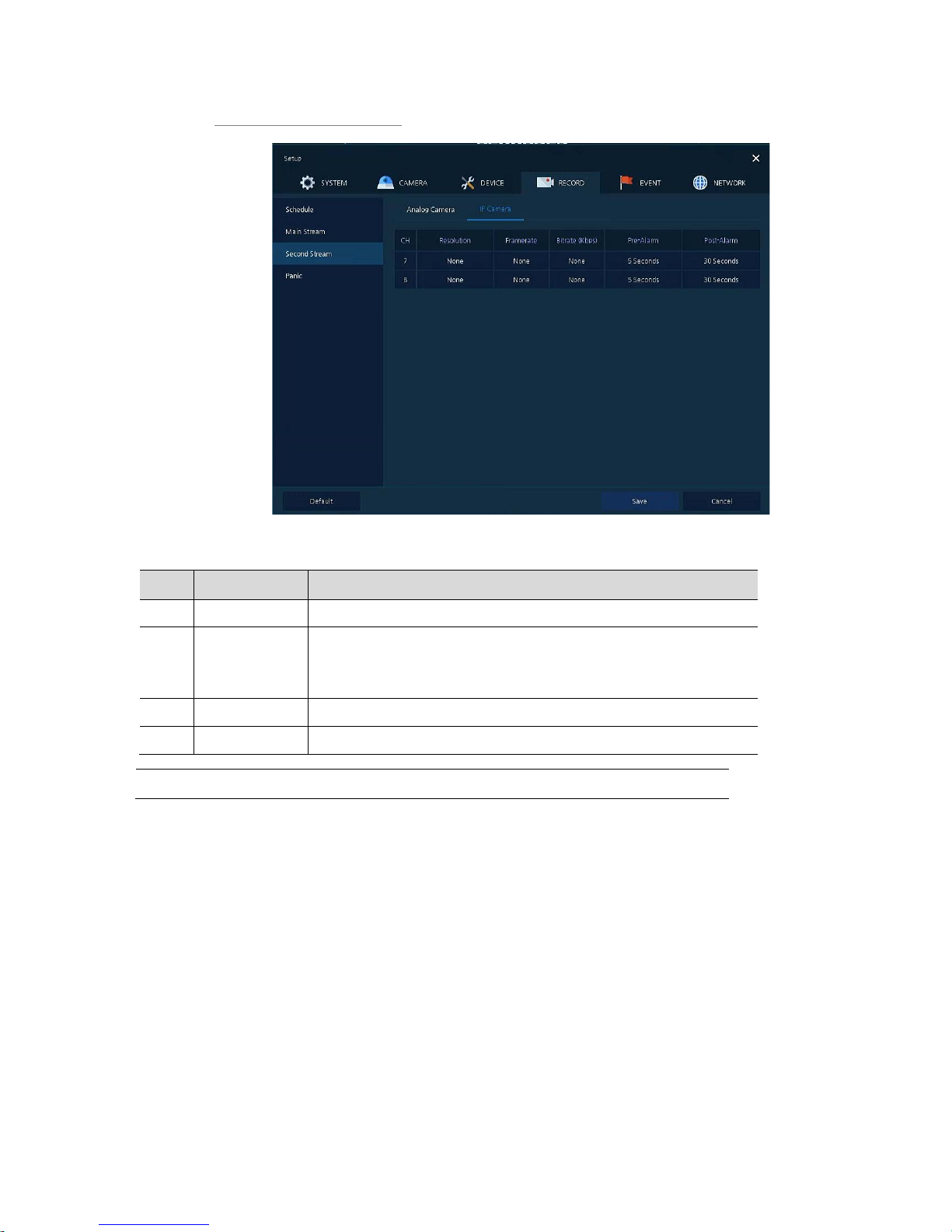
Second Stream > IP Camera
Figure 4-38 RECORD > Second Stream > IP Camera
Table 4-40 RECORD > Second Stream > IP Camera Item and Description
No. Name Function
1 CH Display channels.
2 Resolution
Framerate
Bitrate
Show camera main stream setup status.
5 Pre-Alarm Start recording before set time, if event occurs.
6 Post-Alarm Recording after set time until event ends.
Note
This menu will be appeared when Analog+IP cam mode is selected.
Page 71
67
4.5.5 Panic
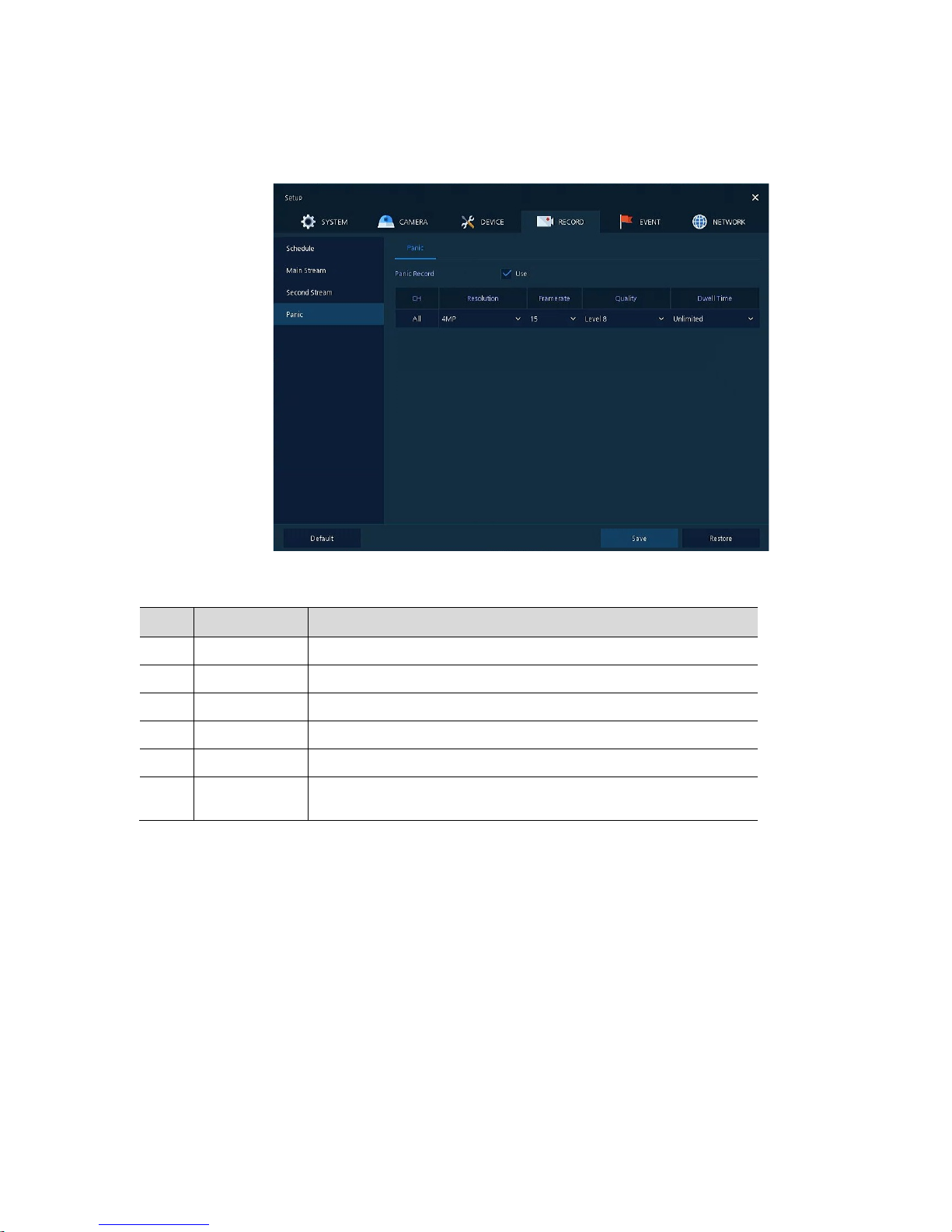
How to set immediate recording
Figure 4-39 RECORD > Stream > Panic
Table 4-41 RECORD > Stream > Panic Item and Description
No. Name Function
1 Panic Record Select/deselect to use immediate recording function.
2 CH Display channels.
3 Resolution Set the resolution of video clips (4MP, 1080P, 720P, 960H).
4 Frame rate Select recording FPS (1-30).
5 Quality Select image quality (Level 1-8).
6 Dwell Time
Select recording duration (No limits , 10 se c, 30 se c, 1 min, 5 min, 10 mi n ,
and 30 min).
Page 72
68
4.6 EVENT
In EVENT, users may set each event of the device.
4.6.1 System/Disk
To set the system and disk event
System/Disk > System
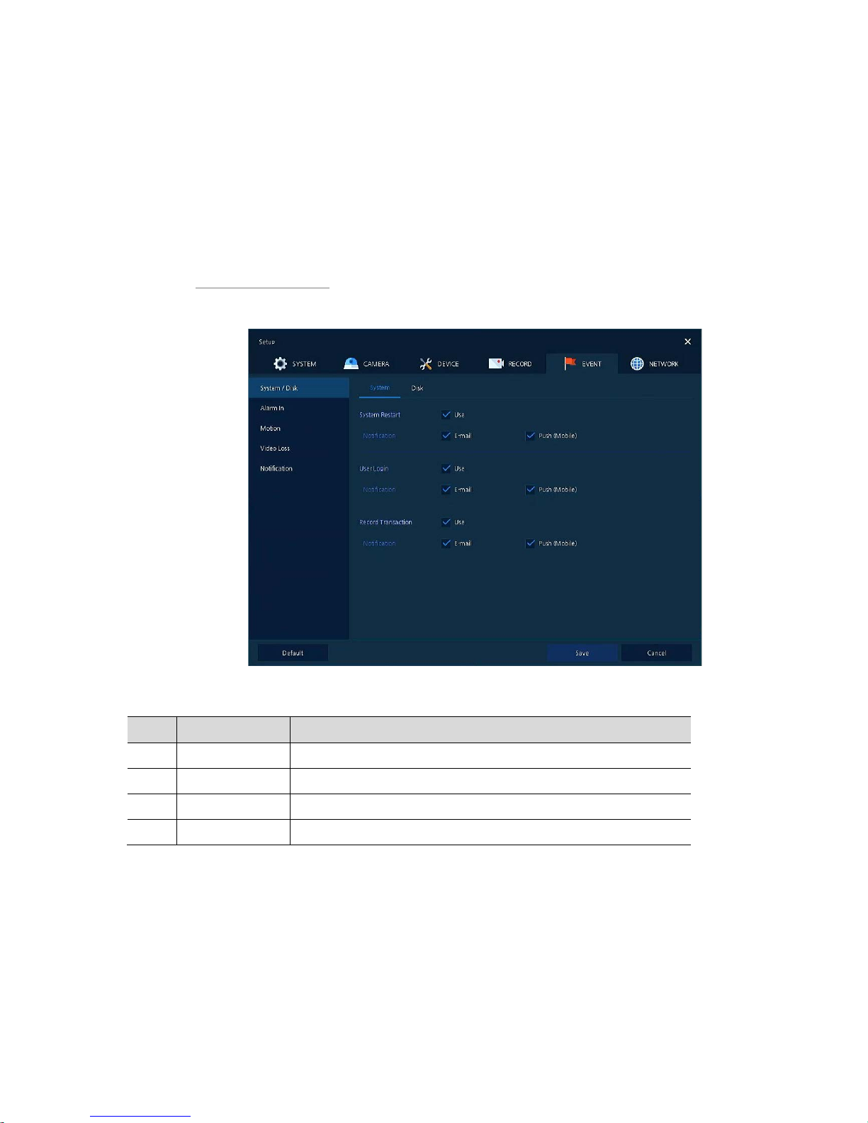
To set the system event of the device
Figure 4-40 Event > System/Disk > System
Table 4-42 Event > System/Disk > System Item and Description
No. Name Function
1 System Restart Select/deselect whether to use system restart event.
2 Notification Select/deselect whether to use mailing or mobile push in case of event.
3 User Login Select/deselect whether to use user-login e vent.
4 Record Transaction Select/deselect whether to use record transaction event.
Page 73
69
System/Disk > Disk
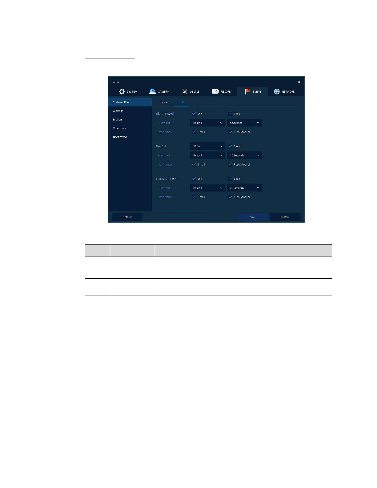
To set disk event
Figure 4-41 Event > System/Disk > Disk
Table 4-43 Event > System/Disk > Disk Item and Description
No. Name Function
1 Disk Unplugged Select/deselect whether to use disk unplugged event.
2 Beep Select/deselect whether to use buzzer sound in case of event.
3 Alarm out
Select to end alarm time (null, Relay1-Keep, 5 sec, 10 sec, 20 sec, 30 sec,
1 min, 10 min, 30 min, and 1 hour).
4 Notification Select/deselect whether to use mailing or mobile push in case of event.
5 Disk Full
Set disk capacity for disk full event (Off, 50%, 60%, 70% , 80%, 90%, and
100%).
6 S.M.A.R.T. Fault Select/deselect whether to use S.M.A.R.T. F ault event of HDD.
Page 74
70
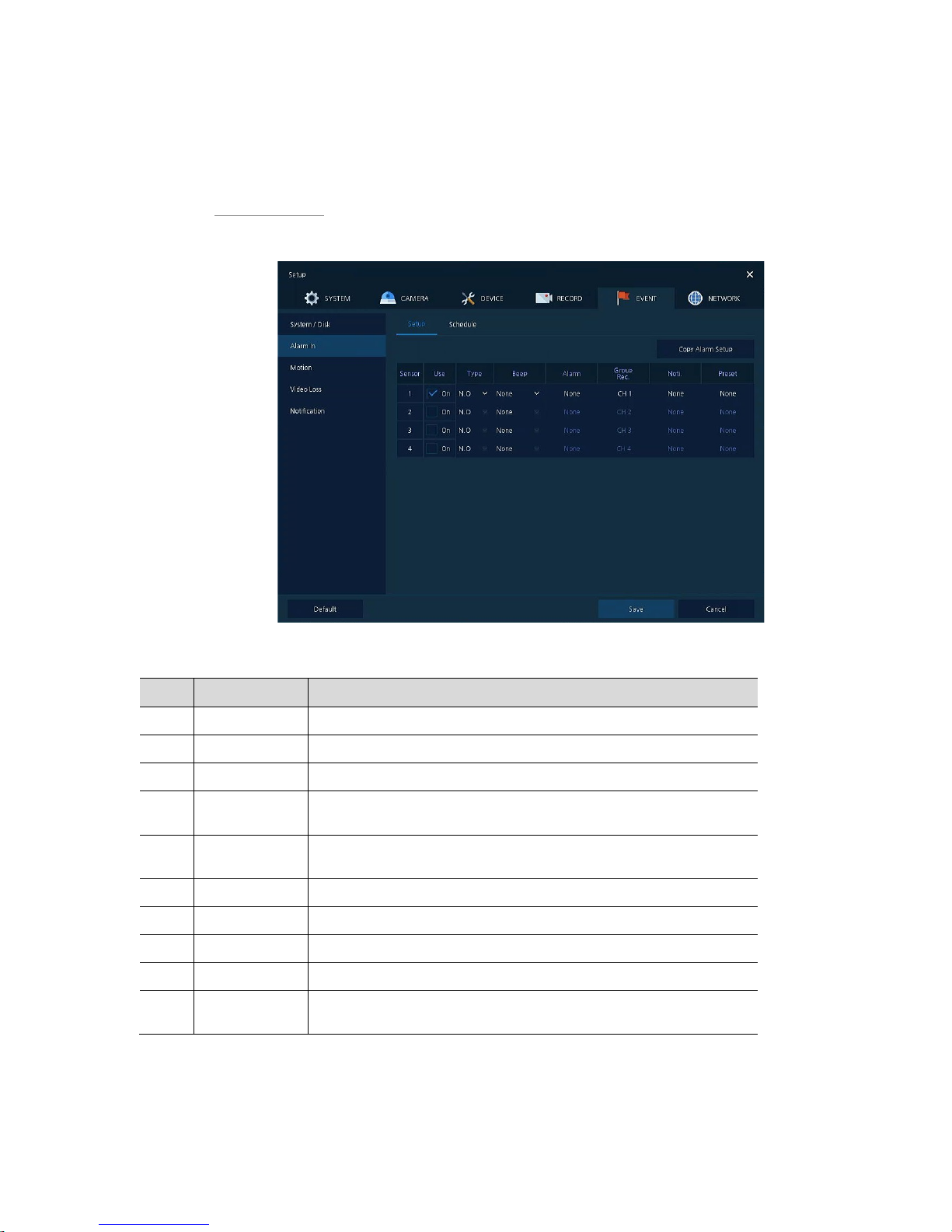
4.6.2 Alarm In
To set sensor alarms and schedule
Alarm In > Setup
To set sensor alarms
Figure 4-42 Event > Alarm In > Setup
Table 4-44 Event > Alarm In > Setup Item and Description
No. Name Function
1 Sensor Display sensor numbers.
2 Use Select/deselect whether to use alarm in the sensor.
3 Type Selec t sen so r types (N.O, N.C).
4 Assign
Select camera channels to designate a sensor (CH 1~4/8/16, immediate
recording).
5 Beep
Select use time of buzzer sound (null, 5 sec, 10 sec, 20 sec, 30 sec, 1 min,
10 min, 30 min, and 1 hour).
6 Alarm Set alarm output.
7 Group Rec. Select the camera to record simultaneously.
8 Noti. Set email notices.
9 Preset Set preset of PTZ camera.
10
Copy to Alarm
Setup
Copy alarm set value to other channels. For more information about set
value copy, see section “4.5.2 Stream > Main Stream in Main Stream.”
Page 75
71
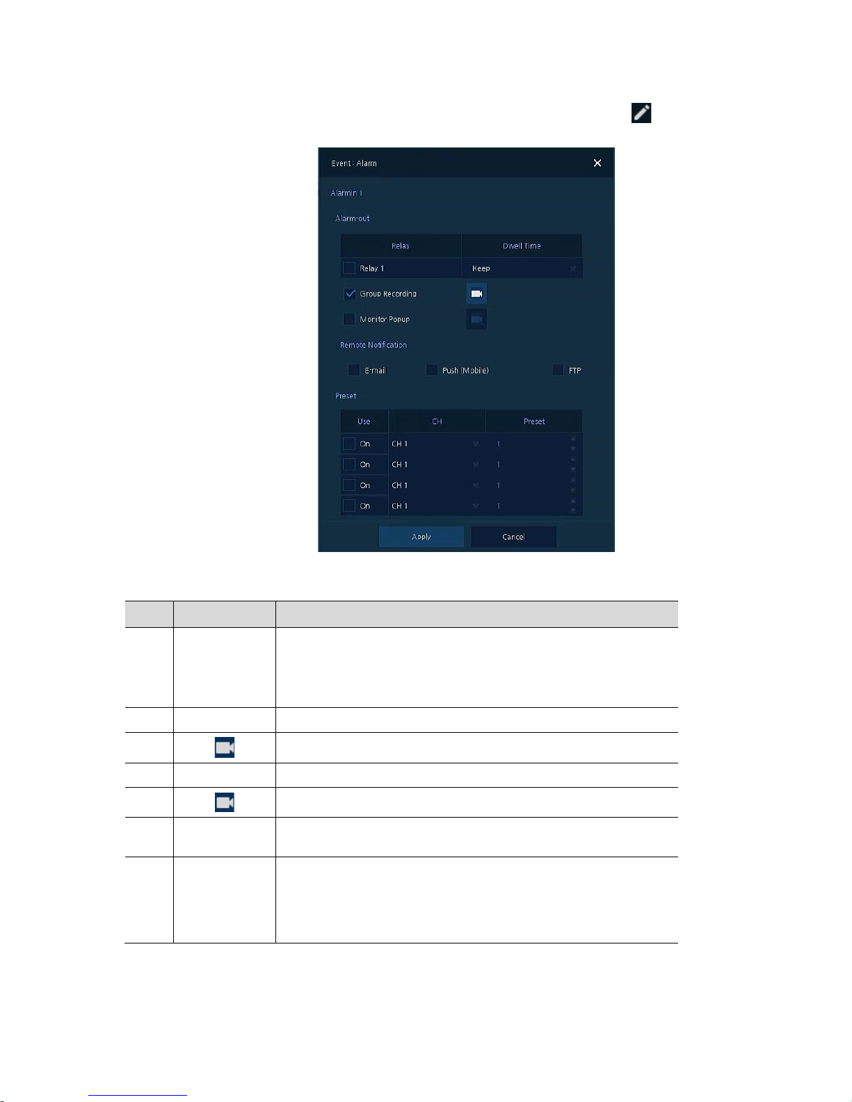
Placing your mouse on Alarm, Group Rec, Noti., Preset and clicking editing Icon( ) in right corner
displays Event : Alarm screen.
Figure 4-43 Event > Alarm In > Setup > Event : Alarm
Table 4-45 Event > Alarm In > Setup > Event : Alarm Item and Description
No. Name Function
1 Alarm-out Set the alarm.
Relay: Select/clear the Relay output checkbox.
Dwell Time: Selecting alarm duration (Keep, 5 sec, 10 sec, 20 sec, 30
sec, 1 min, 10 min, 30 min, and 1 hour)
2 Group Recording Select/deselect whether to use Group Recording.
3
Simultaneous recording camera channel screen opens.
4 Monitor Popup Select/deselect whether to use Monitor Popup.
5
Channel selection screen opens.
6
Remote
Notification
Select/deselect whether to use remote mailing.
7 Preset Preset of PTZ camera is running.
Use: Select/deselect whether to use preset.
CH: Select channels.
Preset: Set preset value.
Page 76
72
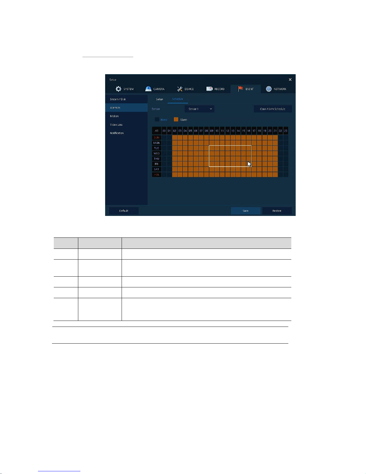
Alarm In > Schedule
To schedule recording time when alarm occurs across device sensors
Figure 4-44 Event > Alarm In > Schedule
Table 4-46 Event > Alarm In > Schedule Item and Description
No. Name Function
1 Sensor Select the sensor to set the schedule.
2
Schedule Type
Selection
Select the types of schedules.
3 Schedule T able Display the schedule users set.
4 Drag Field Display the area dragged with a mouse.
5
Copy to Alarm
Schedule
Copy the schedule on alar m set to othe r se nsor s . F or more i nforma t i on
about set value copy, see section “4.5.2 Stream > Main Stream in Main
Stream.”
Note
For more details about scheduling recording time when alarm occurs across sensors,
see section “4.5.1 Schedule.”
Page 77
73
4.6.3 Motion
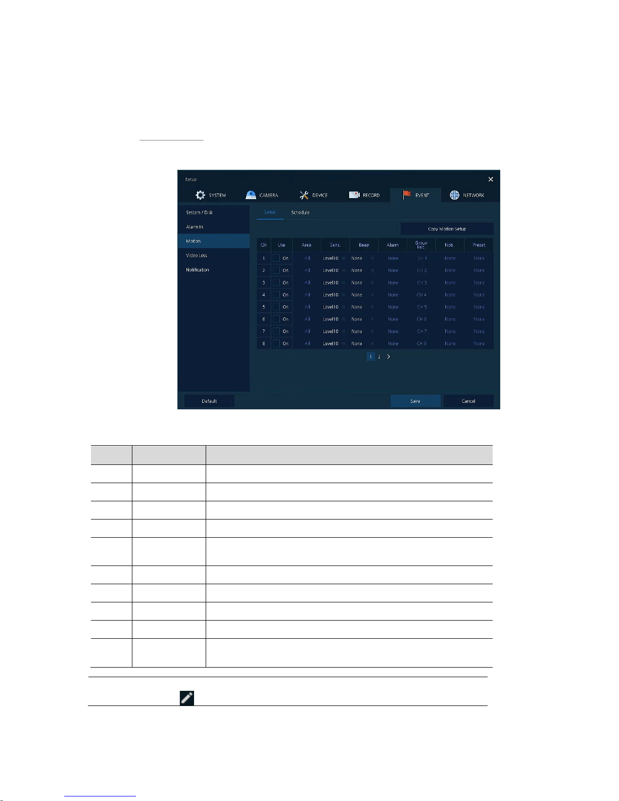
To set and schedule motions across channels
Motion > Setup
To set motions across channels.
Figure 4-45 Event > Motion > Setup
Table 4-47 Event > Motion > Setup Item and Description
No. Name Function
1 CH Display channels.
2 Use Select/deselect whether to use motion function in the channel.
3 Area Display the motion area.
4 Sens. Select the sense level of the motion sensor (Level 1~10).
5 Beep
Select use time of buzzer (null, 5 sec, 10 sec, 20 sec, 30 sec, 1 min, 10
min, 30 min, and 1 hour).
6 Alarm Set alarm output.
7 Group Rec. Select the camera to record simultaneously.
8 Noti. Set email notices.
9 Preset Set preset of PTZ camera.
10
Copy to Motion
Setup
Copy motion set value to other channels. For more information about set
value copy, se e section “4.5.2 Stream > Main Stream in Main Stream.”
Note
Placing your mouse on Alarm, Group Rec, Noti., Preset and clicking editing
icon( ) in right corner displays Event : Alarm screen. For more information about
Page 78
74
Event : Motion screen, see section “4.6.2 Alarm In > Setup in Alarm In.”
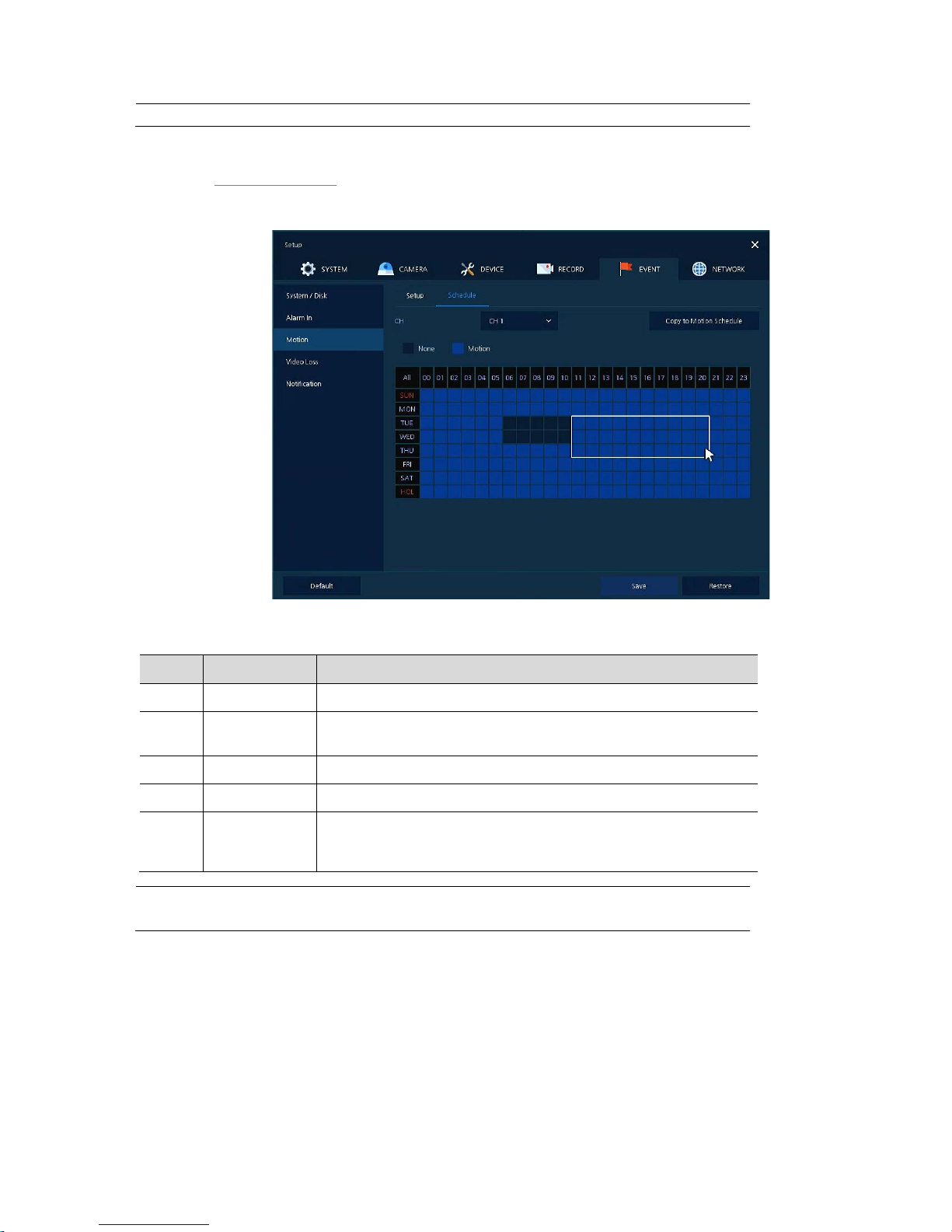
Motion > Schedule
To schedule record time when the motion sensor detects across channels
Figure 4-46 Event > Motion > Schedule
Table 4-48 Event > Motion > Schedule Item and Description
No. Name Function
1 CH Select channels to set schedules.
2
Schedule Type
Selection
Select the types of schedules.
3 Schedule T able Display the schedule users set.
4 Drag Field Display the area dragged with a mouse.
5
Copy to Motion
Schedule
Copy the motion detection schedule to other channels. For more
information about set value copy, see section “4.5.2 Stream > Main
Stream in Main Stream.”
Note
For more information how to schedule record time when the motion sensor detects
across channels, see section “4.5.1 Schedule.”
Page 79
75
4.6.4 Video Loss
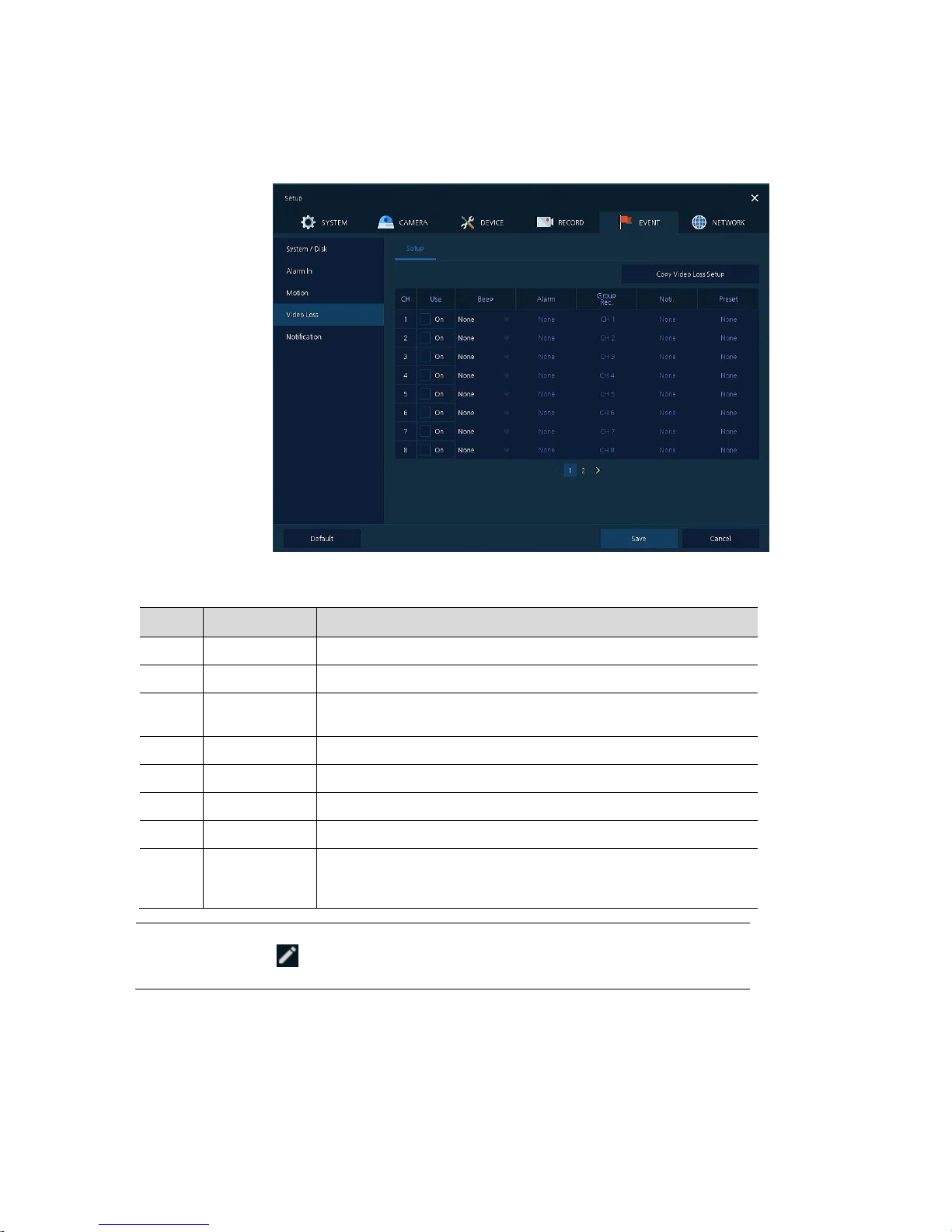
To set Video Loss across channels
Figure 4-47 Event > Video Loss > Setup
Table 4-49 Event > Video Loss > Setup Item and Description
No. Name Function
1 CH Display channels.
2 Use Select/deselect whether to use Video Loss in the channel.
3 Beep
Select use time of buzzer sound (null, 5 sec, 10 sec, 20 sec, 30 sec, 1
min, 10 min, 30 min, and 1 hour).
4 Alarm Set alarm output.
5 Group Rec. Select the camera to record simultaneously.
6 Noti. Set email notices.
7 Preset Set preset of PTZ camera.
8
Copy to Video
Loss Setup
Copy the Video Loss set value to other channels. For more information
about set value copy, see section “4.5.2 Stream > Main Stream in Main
Stream.”
Note
Placing your mouse on Alarm, Group Rec, Noti., Preset and clicking editing
icon( ) in right corner displays Event : Video Loss screen. For more information
about Event : Video Loss screen, see section “4.6.2 Alarm In > Setup in Alarm In.”
Page 80
76
4.6.5 Notification
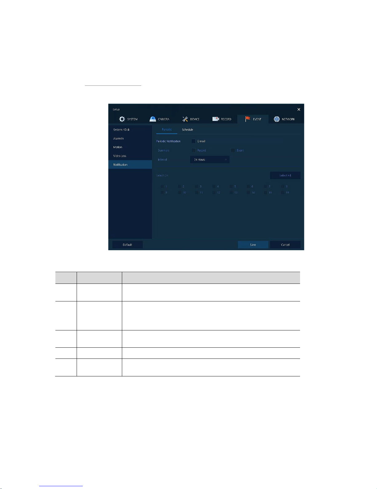
To set and schedule periodical alarms
Notification > Periodic
To set periodical alarms
Figure 4-48 EVENT > Notification > Periodic
Table 4-50 EVENT > Notification > Periodic Item and Description
No. Name Function
1
Periodic
Notification
Select/deselect whether to use periodical alarms.
2 Summary Send the save or event information.
Record: sending the save information
Event: sending the event information
3 Interval
Set the alarm interval (5 min, 10 min, 30 min, and 1 hour, 2-hour, 6-hour,
8-hour, 12-hour, and 24-hour).
4 Select CH Select channels users want.
5
Select All
/Unselect All
Select/deselect all channels.
Page 81
77
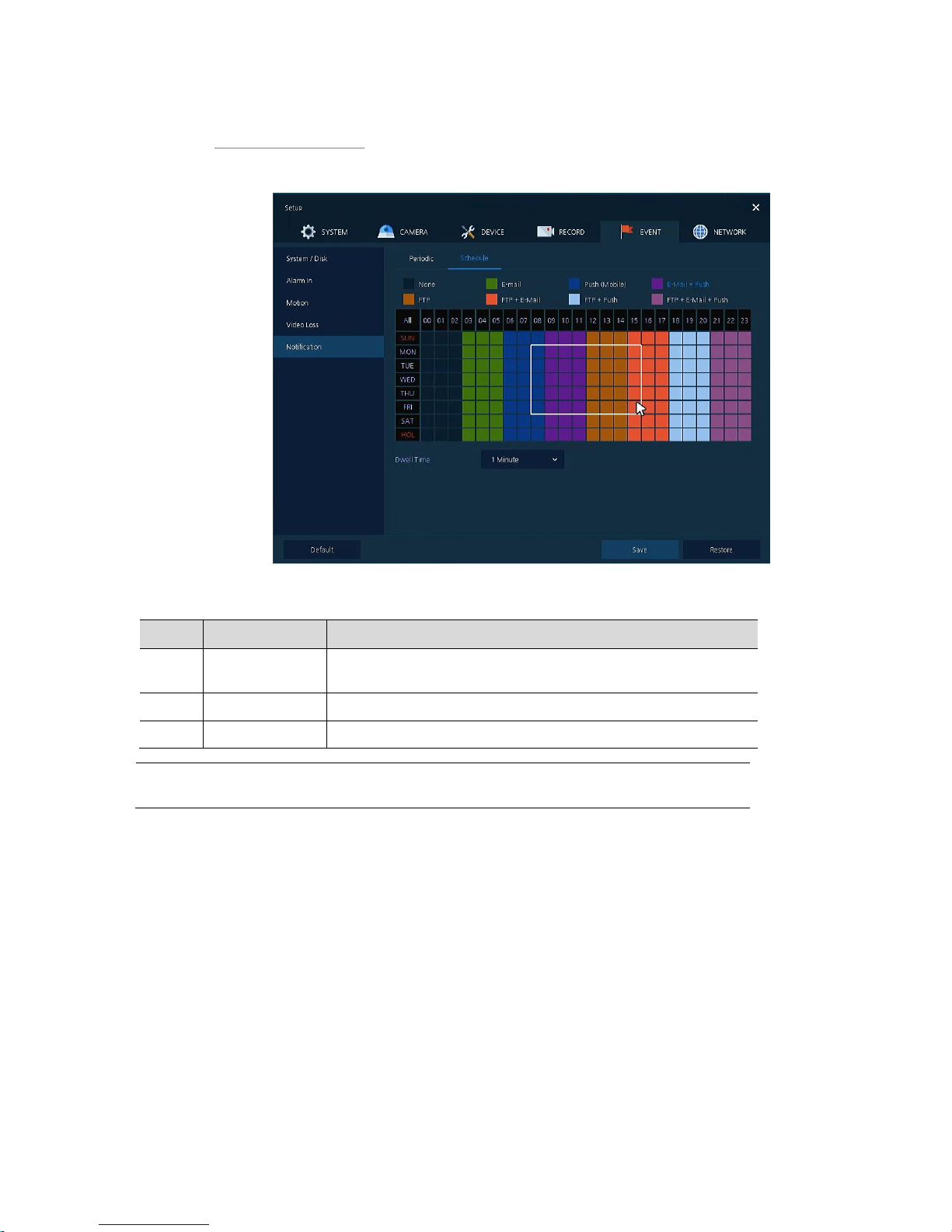
Notification > Schedule
To schedule remote notification (alarm & motion)
Figure 4-49 EVENT > Notification > Schedule
Table 4-51 EVENT > Notification > Schedule Item and Description
No. Name Function
1
Schedule Type
Selection
Select the types of schedules.
2 Schedule Table Display the schedule users set.
3 Drag Field Display the area dragged with a mouse.
Note
For more information how to schedule record time when the alarm is detected, see
section “4.5.1 Schedule.”
Page 82
78
4.7 NETWORK
In NETWORK, users may set the network environment.
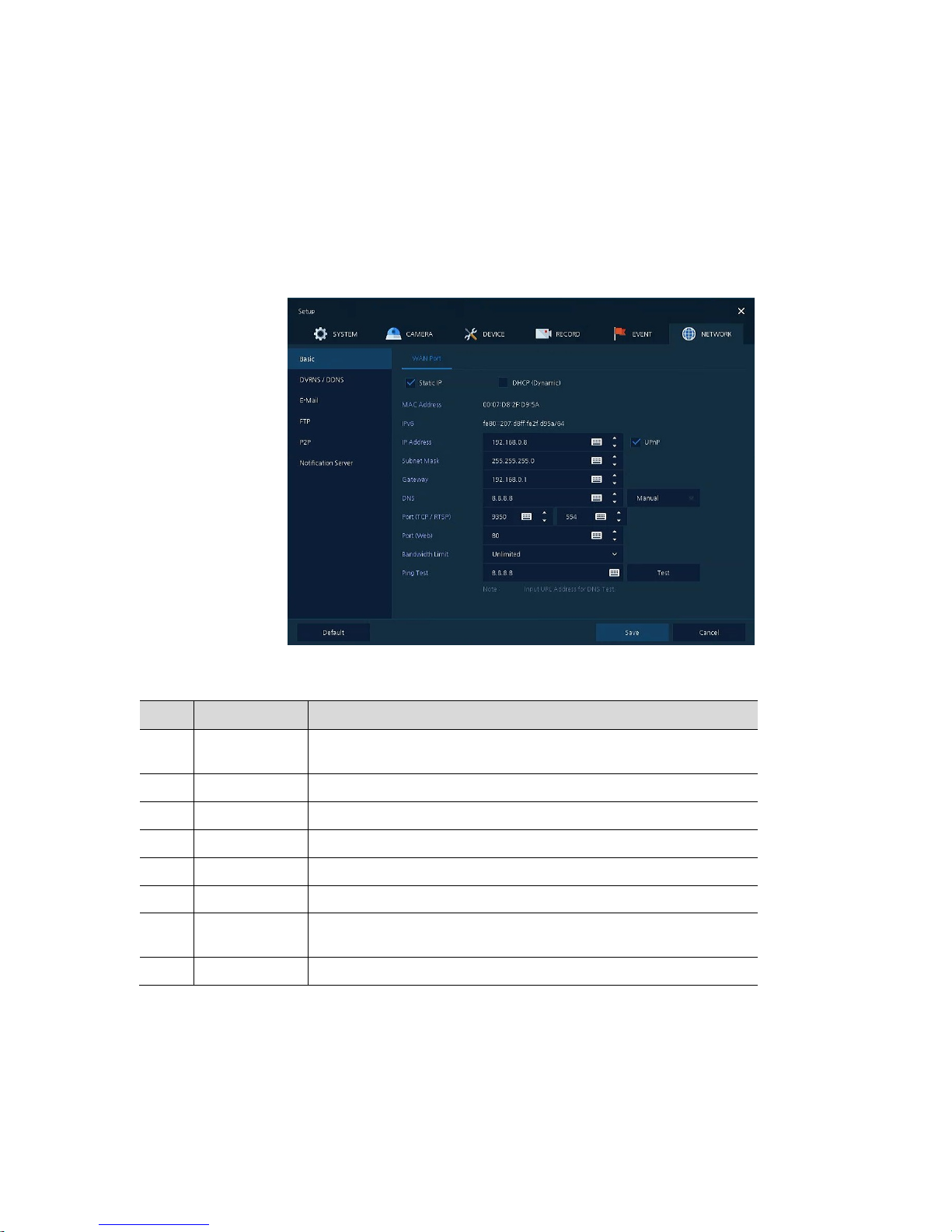
4.7.1 Basic > WAN Port
To set the network environment
Figure 4-50 NETWORK > Basic > WAN Port
Table 4-52 NETWORK > Basic > WAN Port Item and Description
No. Name Function
1 Static IP
Check if you use static IP. For using static IP, enter IP address, Subnet
Mask, and Gateway.
2 DHCP (Dynamic) Select whether to use DHCP (Dynamic).
3 MAC Address Display the MAC Address.
4 DNS Select manual and enter DNS; otherwise choose automatic function.
5 Port (TCP) Enter TCP port.
6 Port (Web) Enter Web port.
7 Bandwidth Limit
Select bandwidth to limit (no limits, 50Mbps, 10Mbps, 5Mbps, 2Mbps,
1Mbps, 500Kbps, 400Kbps, 300Kbps, 200Kbps, and 100Kbps).
8 Ping T est Enter IP in Ping test and implement the text.
Page 83
79
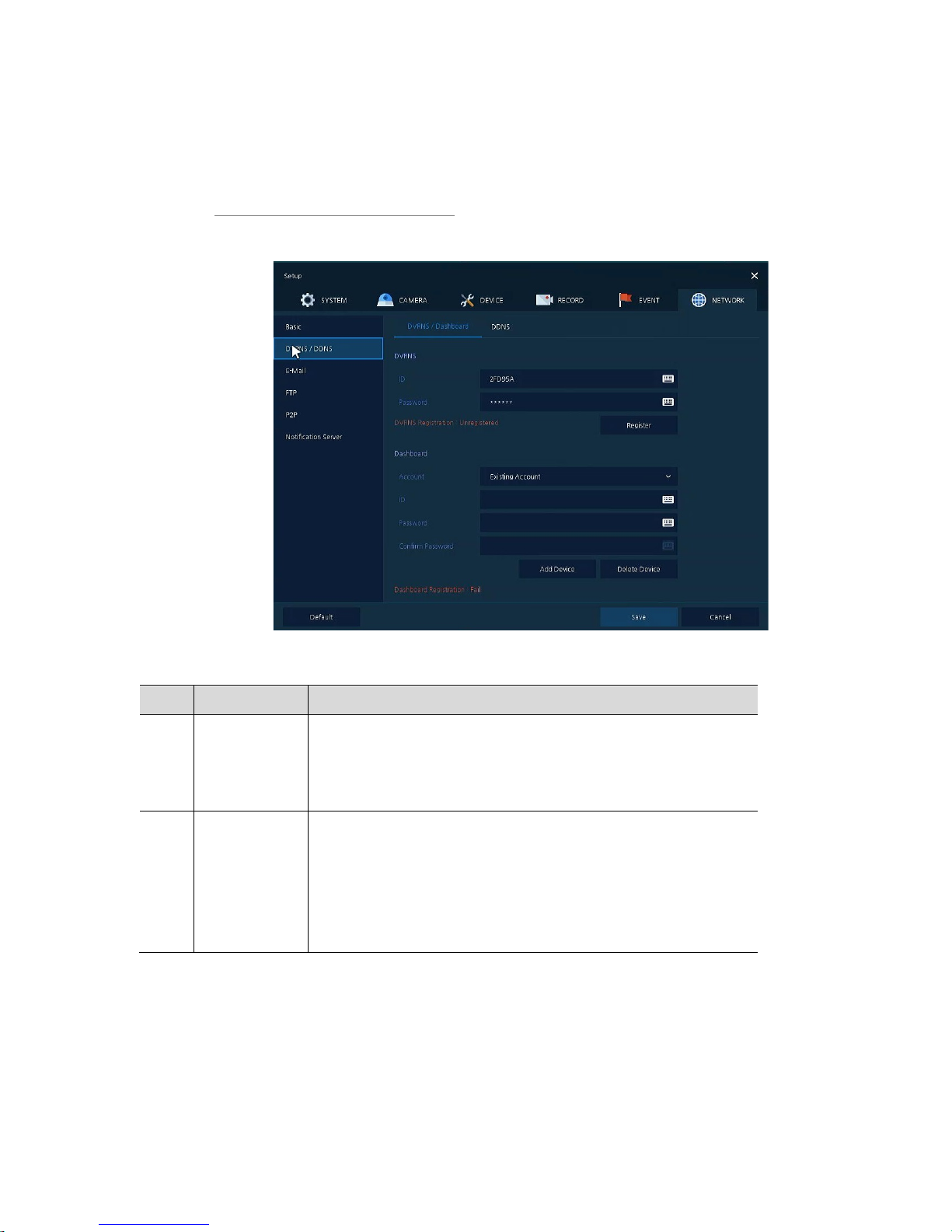
4.7.2 DVRNS/DDNS
To set DVRNS/DDNS
DVRNS/DDNS > DVRNS/Dashboard
To register DVRNS/Dashboard account
Figure 4-51 NETWORK > DVRNS/DDNS > DVRNS/Dashboard
Table 4-53 NETWORK > DVRNS/DDNS > DVRNS/Dashboard Item and Description
No. Name Function
1 DVRNS Register DVRNS account.
ID: Enter DVRNS ID (default: MAC address of the unit)
Password: Enter DVRNS password
Register: Register DVRNS account
2 Dashboard Add/delete Dashboard account.
Account: Select the types of account (Existing Account or New Account)
ID: Enter Dashboard ID
Password: Enter Dashboard password
Add Device: Add Dashboard account
Delete Device: Delete Dashboard account
Page 84
80
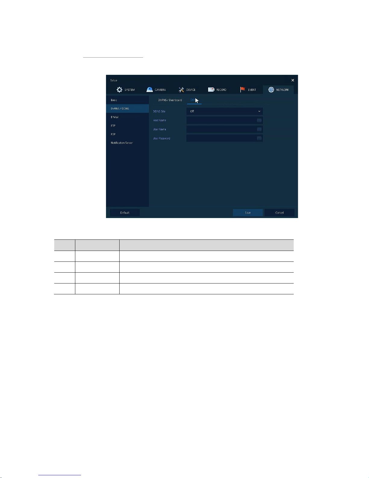
DVRNS/DDNS > DDNS
To set DDNS site for remote users to access in networking
Figure 4-52 NETWORK > DVRNS/DDNS > DDNS
Table 4-54 NETWORK > DVRNS/DDNS > DDNS Item and Description
No. Name Function
1 DDNS Site Select DDNS site.
2 Host Name Enter the host name.
3 User Name Enter the user name.
4 User Password Enter the user password.
Page 85
81
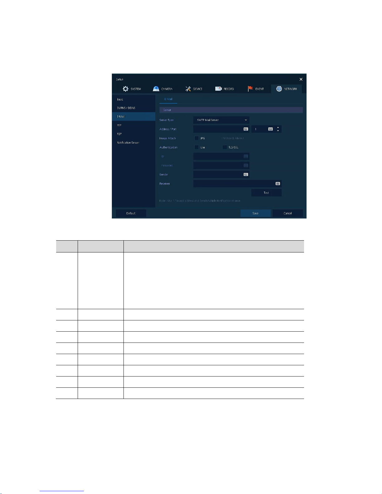
4.7.3 E-Mail
To set email server to send email on the occasion of event
Figure 4-53 NETWORK > E-Mail > E-Mail
Table 4-54 NETWORK > E-Mail > E-Mail Item and Description
No. Name Function
1 Server Type Select SMTP server.
gmail.com
hotmail.com
aol.com
naver.com
daum.com
2 Address/Port Enter server address an d port number.
3 Image Attach Select/deselect whether to attach JPG image.
4 Authentication Select/deselect using authentication and password.
5 ID Enter the email ID.
6 Password Enter the email password.
7 Sender Write the sender.
8 Receiver Write the receiver.
9 Test Verify whether the email server is set normally.
Page 86
82
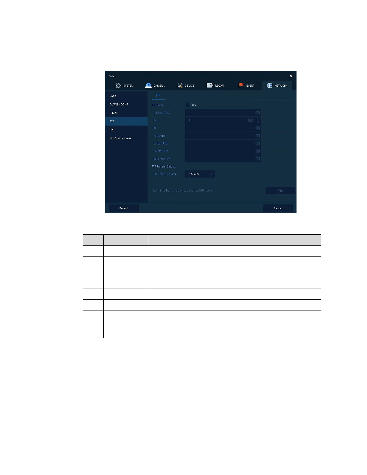
4.7.4 FTP
Set up FTP server to send video to FTP server. The file format is AVI file.
Figure 4-55 NETWORK > FTP > FTP
Table 4-55 NETWORK > FTP > FTP
No. Name Function
1 FTP Server Select whether to use FTP.
2 Address(URL)/Port Enter server address and port.
3 ID, Password Enter ID & Password of server.
4 Upload Path Enter upload directory.
5 Create Folder Enter desired folder name.
6 Base File Name Enter desired file name.
7
FTP Transfer
Settings
Select max file time (1, 5, 10, 15minutes). The file format is AVI file.
8 Test Verify whether the FTP server is set normally.
Page 87
83
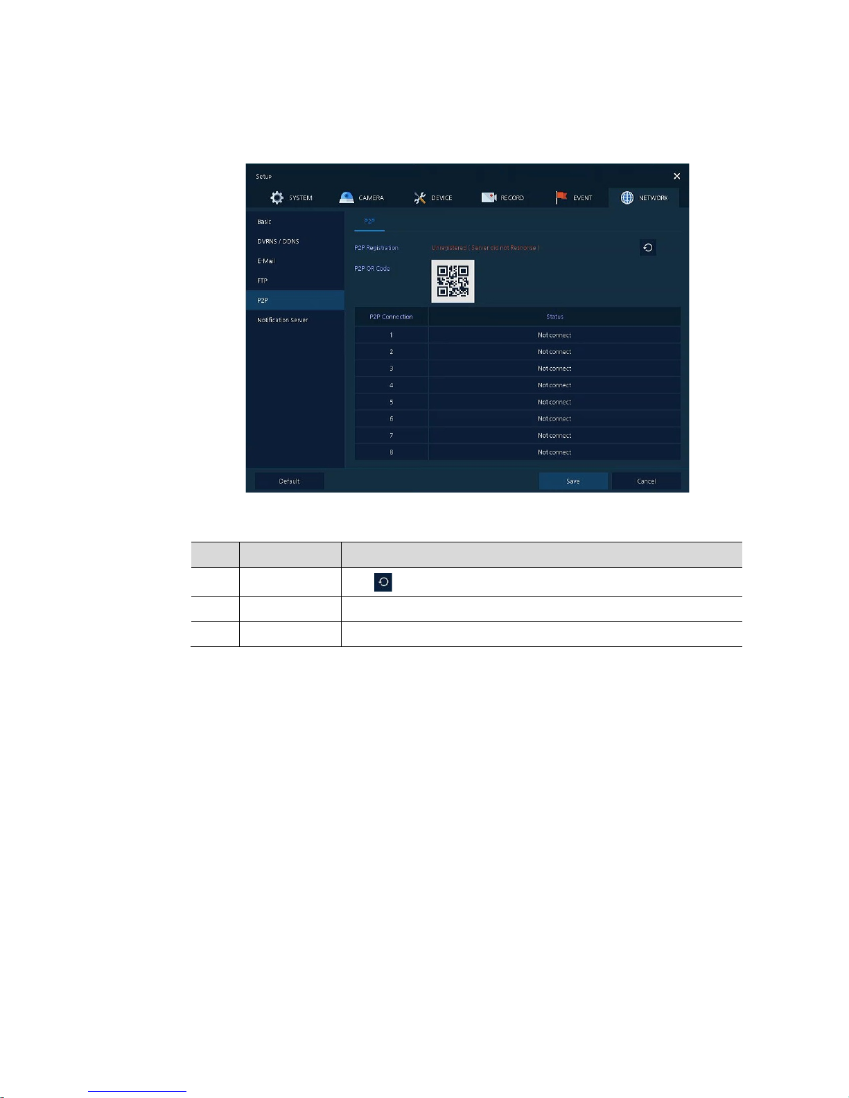
4.7.5 P2P
User can connect recorder from mobile app using QR code scan.
Figure 4-56 NETWORK > P2P > P2P
Table 4-56 NETWORK > P2P > P2P
No. Name Function
1 P2P Registration
Click button to check up registration status.
2 P2P QR Code Scan QR code using mobile app to connect recorder.
3 P2P Connection Display connection status.
Page 88
84
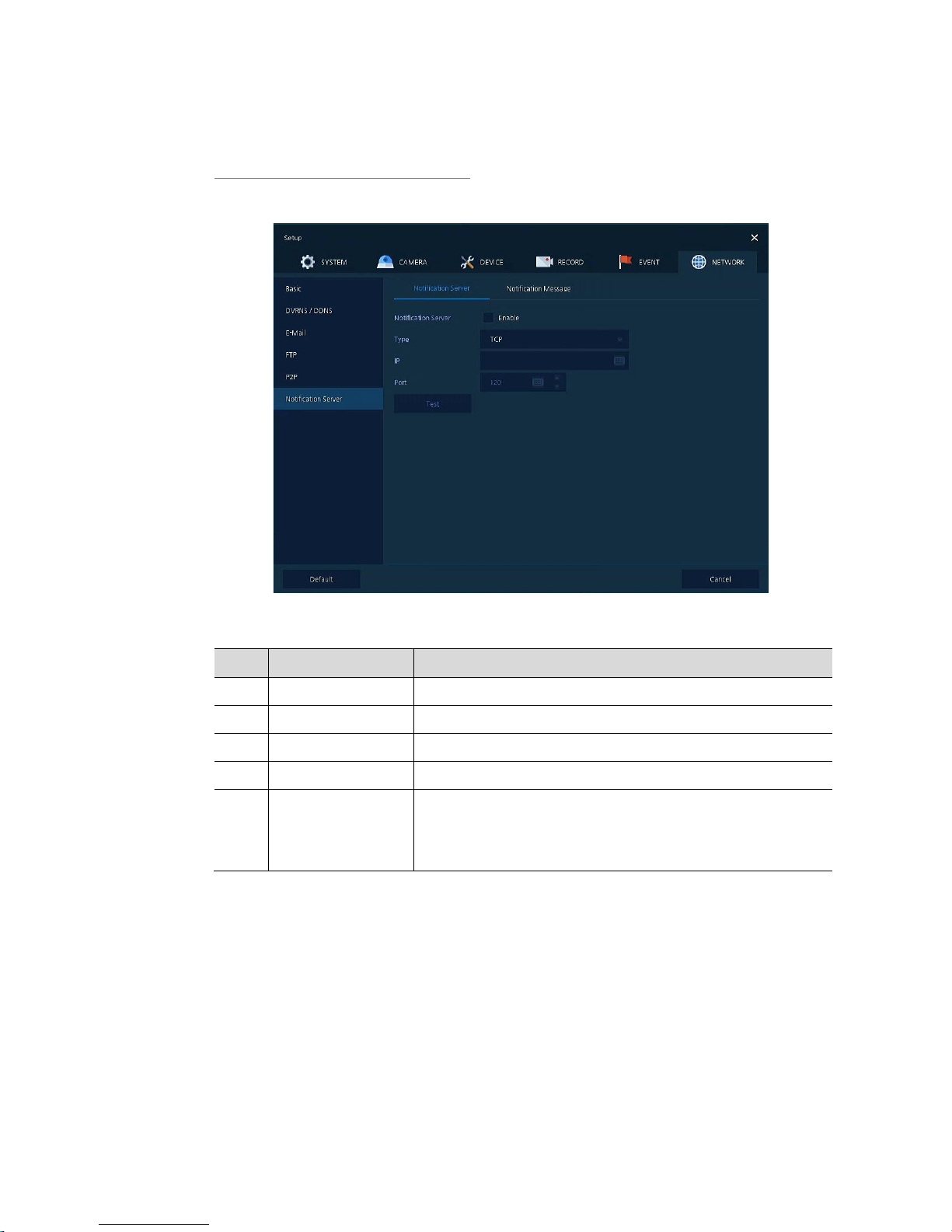
4.7.6 Notification Server
Notification Server > Notification Server
Figure 4-57 NETWORK > Noti ficat io n Se rv er > Notification Server
Table 4-57 NETWORK > Notificatio n Se rv er > Notification Server
No. Name Function
1 Notification Server Select/deselect whether to use Notification Server.
2 Type Select TCP or UDP Protocol.
3 IP Enter the server IP address or host name.
4 Port Enter the server port.
5 Test
Send a test message to the server to check the connection status.
Click Save button when the transmission is successful.
TCP can check the results in the recorder, but UDP should be checked
in the notification server.
Page 89
85
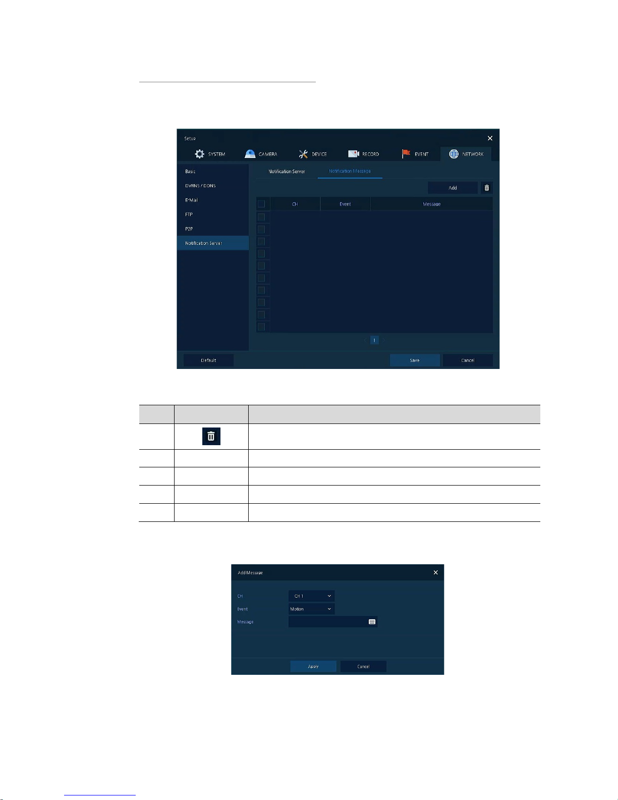
Notification Server > Notification Message
Set up the message to be sent to the notification server when event occurs.
Figure 4-58 NETWORK > Notification Server > Notification Message
Table 4-58 NETWORK > Notificatio n Se rv er > Notification Message
No. Name Function
1
Deleted registered notification message.
2 Add Notification message edit window pop-up.
3 CH Camera channel.
4 Event Display event type as Motion, Alarm or Video Loss.
5 Message Display notification message.
Clicking Add opens Add Message
Figure 4-59 NETWORK > Notification Server > Notification Message > Add Message
Page 90

86
Table 4-59 NETWORK > Notificatio n Se rv er > Notification Message > Add Message
No. Name Function
1 CH Select the channel to add a message.
2 Event Select the even t t ype (motion, alarm, video loss).
3 Message Create a message to send.
Page 91
87
5. Search/Playback
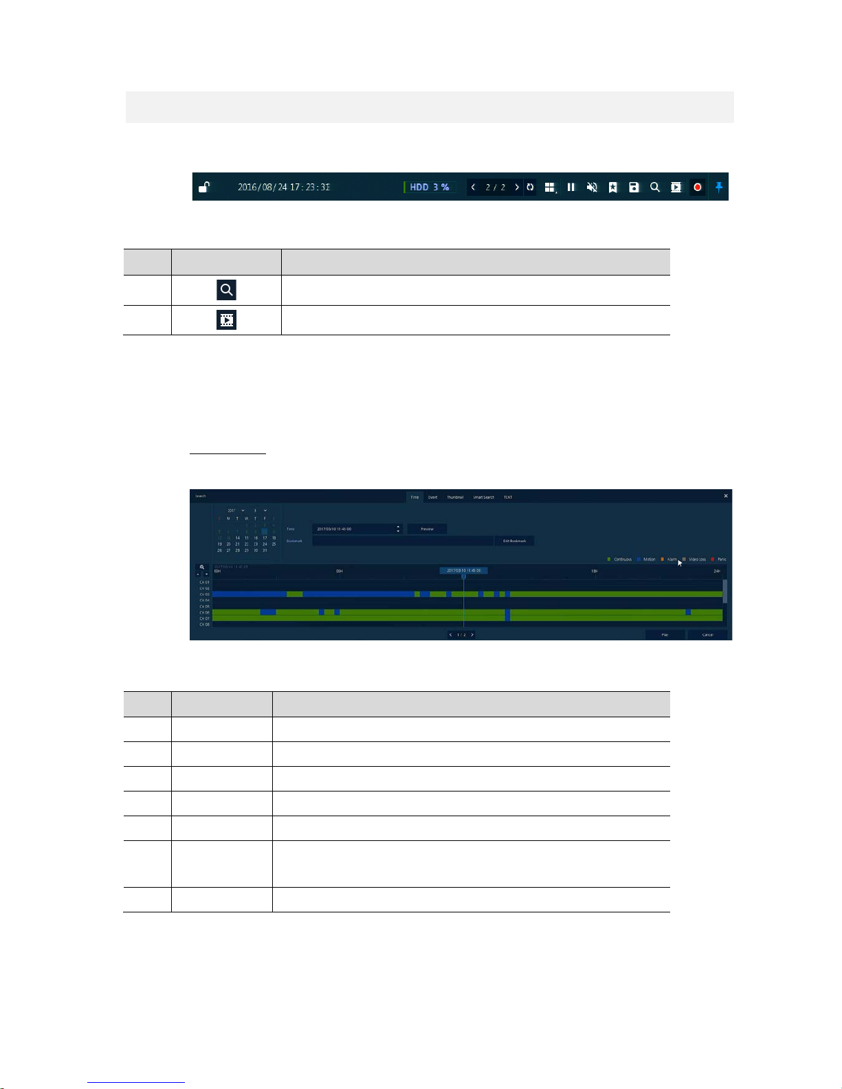
This chapter describes Live Launcher search and play menu in the below screen bar .
Figure 5-1 Live Launcher Search, Play menu
Table 5-1 Item and Description of Live Launcher Search, Play menu
No. Item Description
1
Search recorded data (time, event, thumbnail, smart search and text).
2
Playback recorded data.
5.1 Search
This function searches recorded data as Time, Event, Thumbnail, Smart Search and Text.
Search > Time
Recording data is searched by date and time.
Figure 5-2 Search: Time
Table 5-2 Search: Time Item and Description
No. Item Description
1 Calendar Selecting the date to search.
2 Time Setting time to search.
3 Bookmark Selecting a bookmark to search.
4 Timeline Display timelines across channels.
5 Preview Previewing video clips searched.
6 Play
Playing video clips. For more information about Live bar, see section “5.2
Playback”.
7 Cancel Ending search screen.
Page 92
88
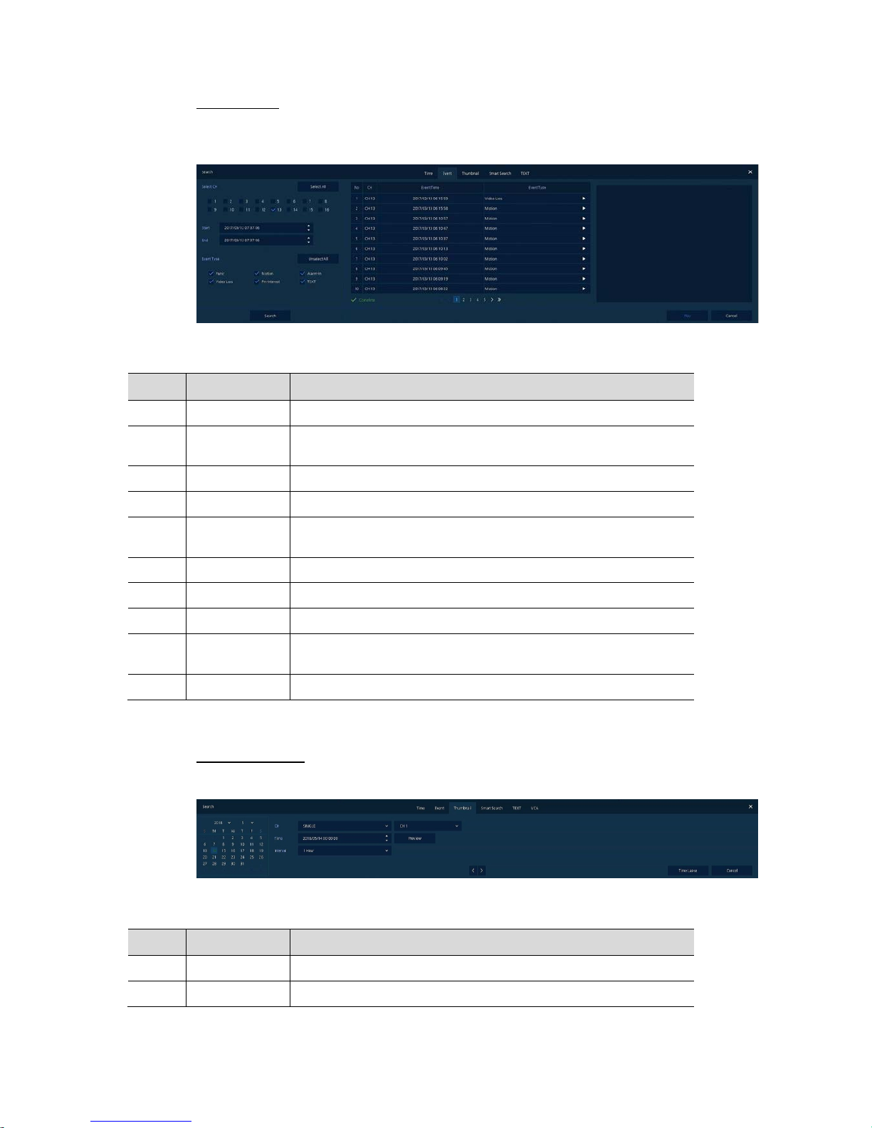
Search > Event
Recording data is searched by event type.
Figure 5-3 Search: Event
Table 5-3 Search: Event Item and Description
No. Item Description
1 Select CH Select channels to search.
2
Select All
/Unselect All
Select/deselect all channels.
3 Start Setting starting time to search.
4 End Setting ending time to search.
5 EVENT TYPE
Selecting the types of event (immediate recording, motion, Alarm-In,
Video Loss, and bookmar k) .
6 Search Searching the event.
7 Event List Displaying event list searched.
8 Thumbnail Field Displaying thumbnail images of selected event.
9 Play
Playing video clips selected. For more information about Live bar, see
section “5.2 Playback”.
10 Cancel Ending search screen.
Search > Thumbnail
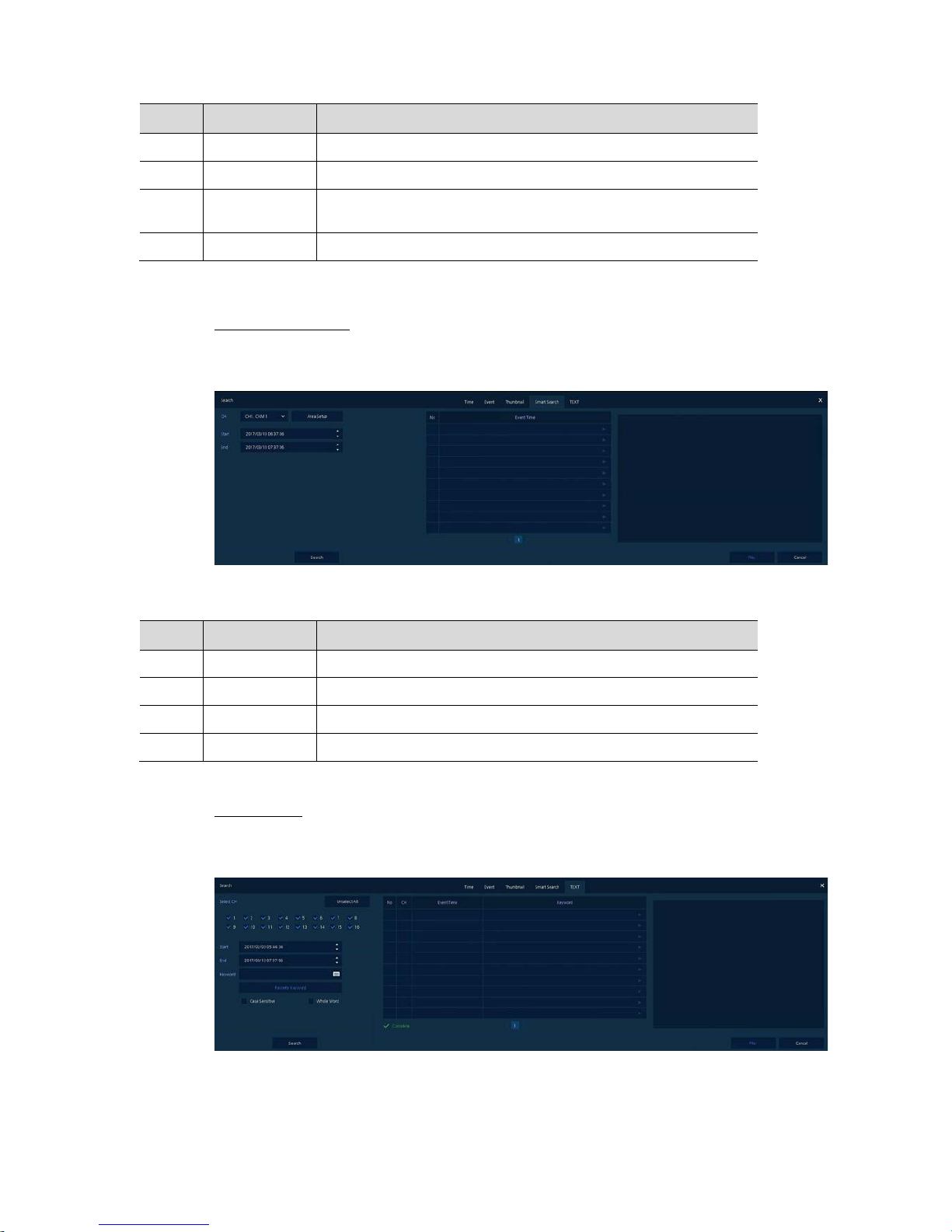
Recording data is searched and played back as a thumbnail image at intervals of time.
Figure 5-4 Search: Thumbnail
Table 5-4 Search: Thumbnail Item and Description
No. Item Description
1 Calendar Selecting dates to search.
2 CH Selecting channels to search.
Page 93
89
No. Item Description
3 Time Selecting time to search.
4 Interval Setting time interval for searching images.
5
Time
Lapse/Pause
Playing or stopping videos searched.
10 Cancel Ending search screen.
Search > Smart Search
Recording data is searched by detecting change of specific area.
Figure 5-5 Search: Smart Search
Table 5-5 Search: Smart Search Item and Description
No. Item Description
1 CH Selecting channels to search.
2 Area Setup Select area to search motion event.
3 Start Setting starting time to search.
4 End Setting ending time to search.
Search > TEXT
Recording data is searched by keyword.
Figure 5-6 Search: TEXT
Page 94

90
Table 5-6 Search: TEXT Item and Description
No. Item Description
1 Select CH Select channels to search.
2
Select All
/Unselect All
Select/deselect all channels.
3 Start Setting starting time to search.
4 End Setting ending time to search.
5 Keyword Entering keyw o r d to search.
6 Case Sensitive Searching items in case-sensitive.
7 Whole Word Searching items that include all words.
8 Search Searching the event.
9 Event List Displaying event list searched.
10 Thumbnail Field Displaying thumbnail images of selected event.
11 Play
Playing video clips selected. For more information about Live bar, see
section “5.2 Playback”.
12 Cancel Ending search screen.
Page 95
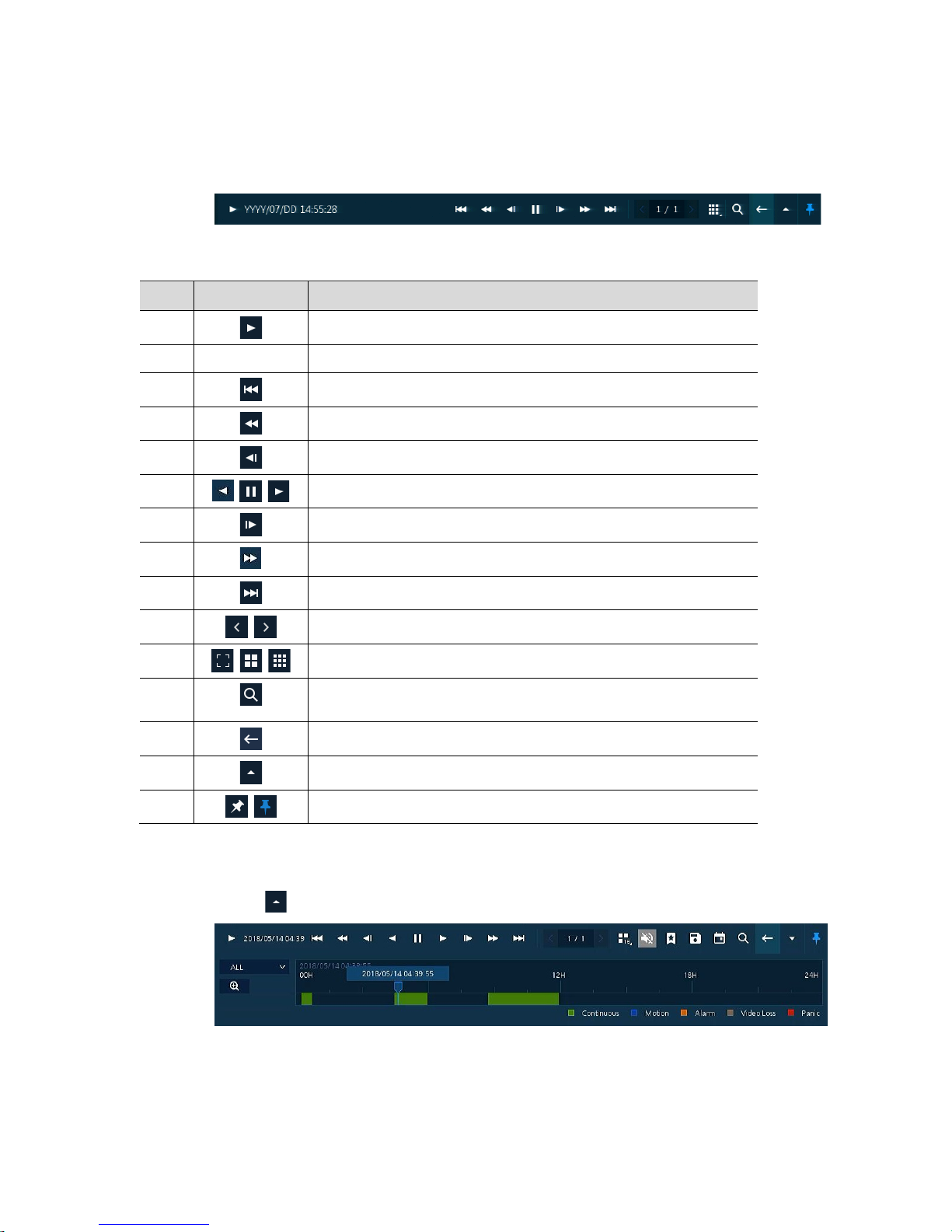
91
5.2 Playback
To play recorded data
Figure 5-7 Playback Launcher
Table 5-7 Playback Launcher Item and Description
No. Item Description
1
Displaying present play status.
2 Date and Time Displaying date and time of playing videos.
3
Moving to the first section of the video.
4
Playing the videos with multiplied speed in reverse (2~64x).
5
Playing the videos with lower speed in reverse (1/2~1/8x).
6
Play backward, forward and pause the videos.
7
Play forward step.
8
Play fast forward(2~64x).
8
Go to last section of the video.
9
Moving to previous/next partition screens.
10
Selecting the partition mode to mark in the screen.
11
Searching the recorded data (time, event, thumbnail, smart search and
text). For more information about search, see section “5.1 Search”.
12
Closing playing videos and moving to live screen.
13
Opening or closing the record timelines.
14
Activating/deactivating automatic hidden function of Launcher menu.
Clicking opens Record Time-Line.
Figure 5-8 Playback Launcher > Record Time-Line
Page 96
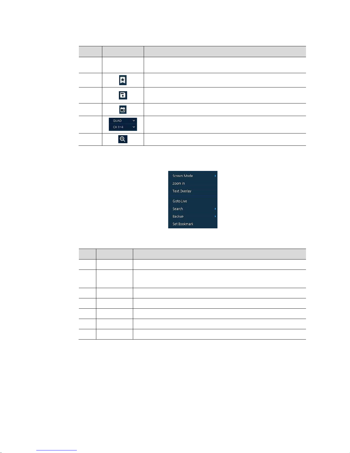
92
Table
5-8 Playback Launcher > Record Time-Line Item and Description
No. Name Function
1 Time lines
Shows the recording status. Select the
desired time with the mouse to
playback.
Add bookmarks at the selected time in the Time line.
2
Run a Manual backup. Se e “3.2.1 Backup
”
to display detai led informati on
about back-up.
3 Open the calendar window and select a date from the calendar.
4 Show time bar by single channel, 4channels or all channels.
5 Show time line by 1hour or 24hours (toggle).
Click mouse right button to open quick menu in the playback mode.
Figure 5-9 Playback Qui ck menu
Table 5-9 Playback Quick menu
No. Item Description
1 Screen Mode Select the partition mode of live screen (Full, 2X2, 3X3, and 4x4).
2 Zoom in
Magnify selected live screen (2x, 4x 8x).
This menu is shown full screen mode only.
3 Text Overlay POS text overlay on the screen. This menu is shown when enable Text menu.
4 Goto Live Stop playback and return to live mode.
5 Search Open Search window.
6 Backup Open manual backup menu.
7 Set Bookmark Save the bookmark
Page 97
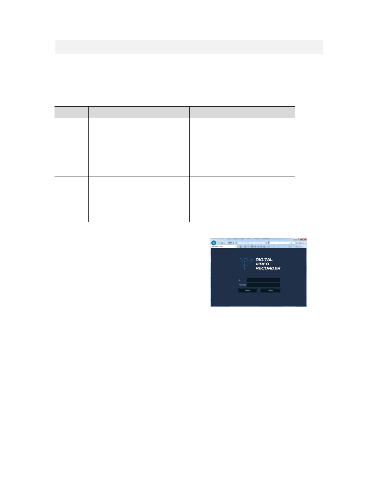
93
6. Webviewer
This chapter describes webviewer for monitoring videos through a PC in remote mode.
How to monitor with webviewer.
Table 6-1 System Requirement for Webviewer
Item Recommended Minimum
OS
MicrosoftⓇ WindowsⓇ 10 x86(64bit)
(Home Premium, Professional, Ultimate)
MicrosoftⓇ WindowsⓇ 8(pro, Enterprise)
MicrosoftⓇ WindowsⓇ XP Home SP3
CPU Intel CoreTM i5-2550 3.30GHz or higher
Intel CoreTM 2 Duo E7200 2.53GHz or
higher
RAM 2GB or higher 1.5GB or higher
VGA
ATI RadeonTM HD 3650 or NVIDIA
GeForce 8400GS or higher(1280x1024,
32bpp or Higher), Multi Monit or
ATI RadeonTM HD 2400 or NVIDIA GeForce
FX5500 or higher(1024x768, 24bpp or
higher)
HDD Over 6GB Over 1GB
LAN Gigabit Ethernet 10/100 Mbps Ethernet
1 Enter IP address of a recorder in
Internet browser.
2
Enter ID and Password, and then click the
button.
Viewer: playing NVR Live images
Setup: setting menu in similar ways
with NVR connected monitor.
For using Viewer, users need to download Java. The way to download is shown as follows:
Page 98
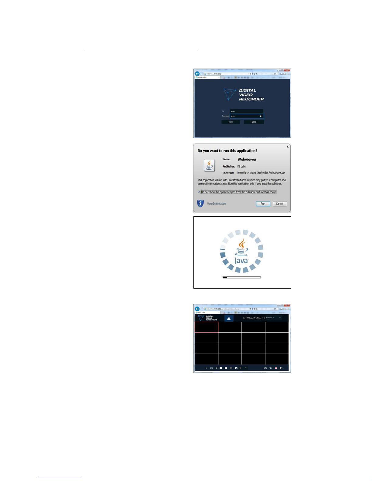
94
In case of selecting Viewer(Internet Explorer)
1 Click Viewer.
2
When Java download screen opens,
download and install JAVA.
3 Live images may be monitored.
Page 99
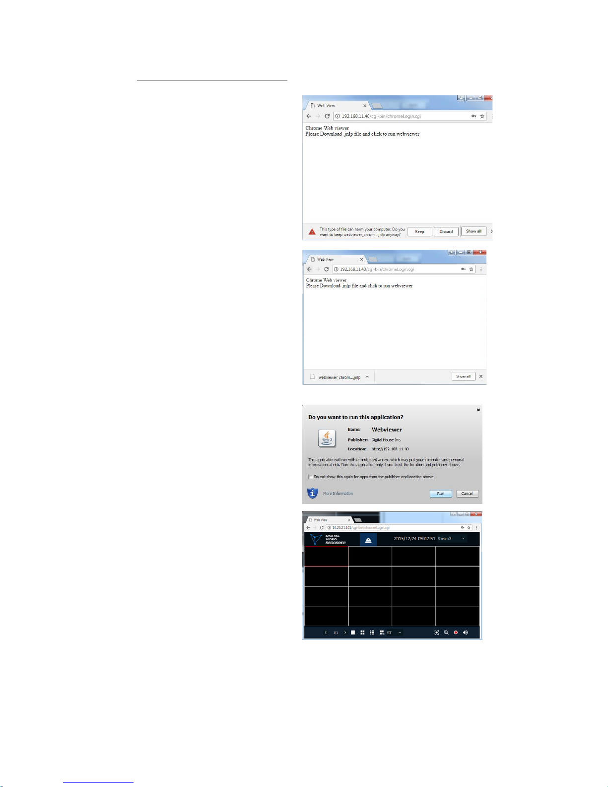
95
In case of selecting Viewer(Chrome)
1
After click Viewer, .jnlp file can be
downloaded.
Click Keep button.
2 Click webviewer_chrome.jnlp.
3
When Java download screen opens,
download and install JAVA.
4 Live images may be monitored.
Page 100
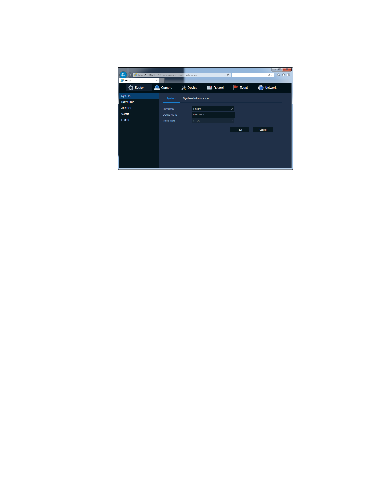
96
In case of selecting Setup
Users can set the menu in similar ways with NVR connected monitor.
Figure 6-1 Setup screen
 Loading...