

Eneo HDR-4004AM1 Instruction Manual
INSTRUCTION MANUAL (HDR-4004AM1.0_User Guide_V1.0)
H.264 Video Compression
Digital Video Recorder
About this user guide
Before installing and using this unit, please read this user guide carefully.
Be sure to keep it handy for later reference.
2
Safety Precautions
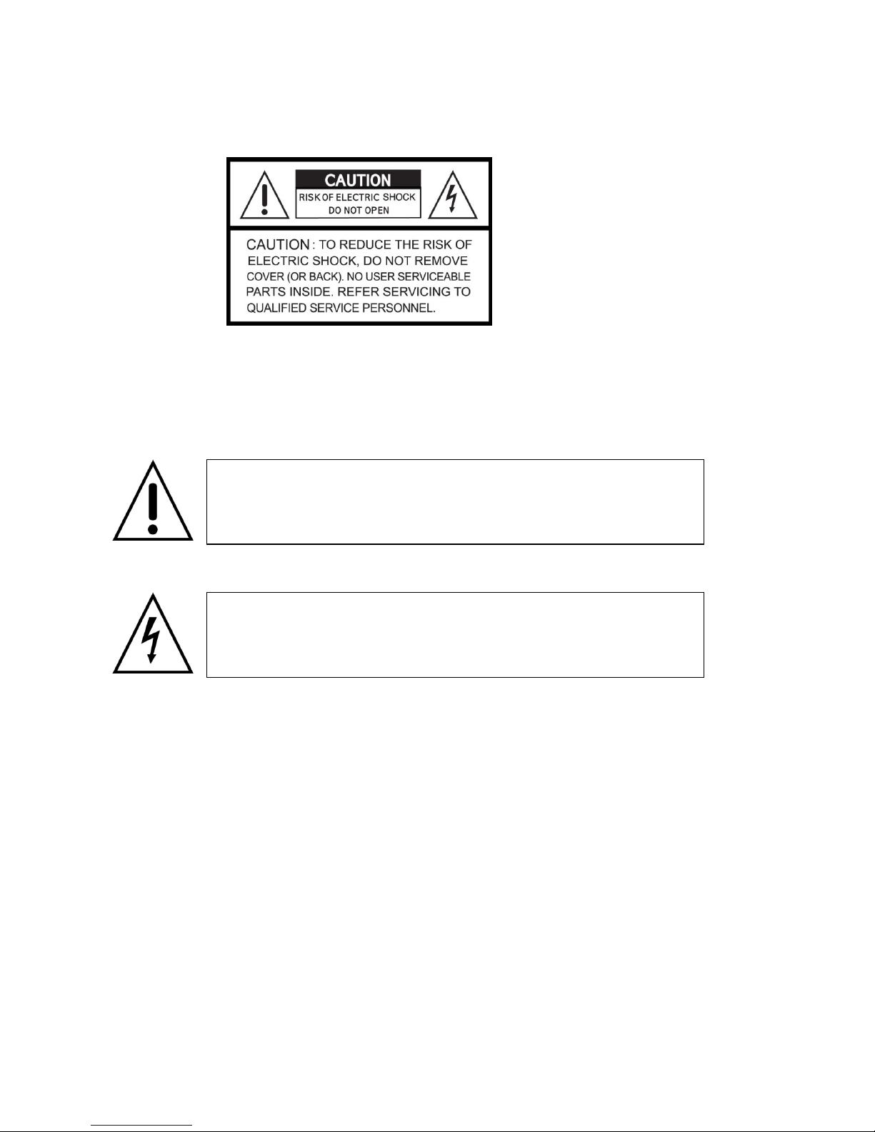
Explanation of Graphical Symbols
WARNING
To reduce a risk of fire or electric shock, do not expose this product to rain or moisture.
CAUTION
Changes or modifications not expressly approved by the manufacturer may void the user’s authority to
operate this equipment.
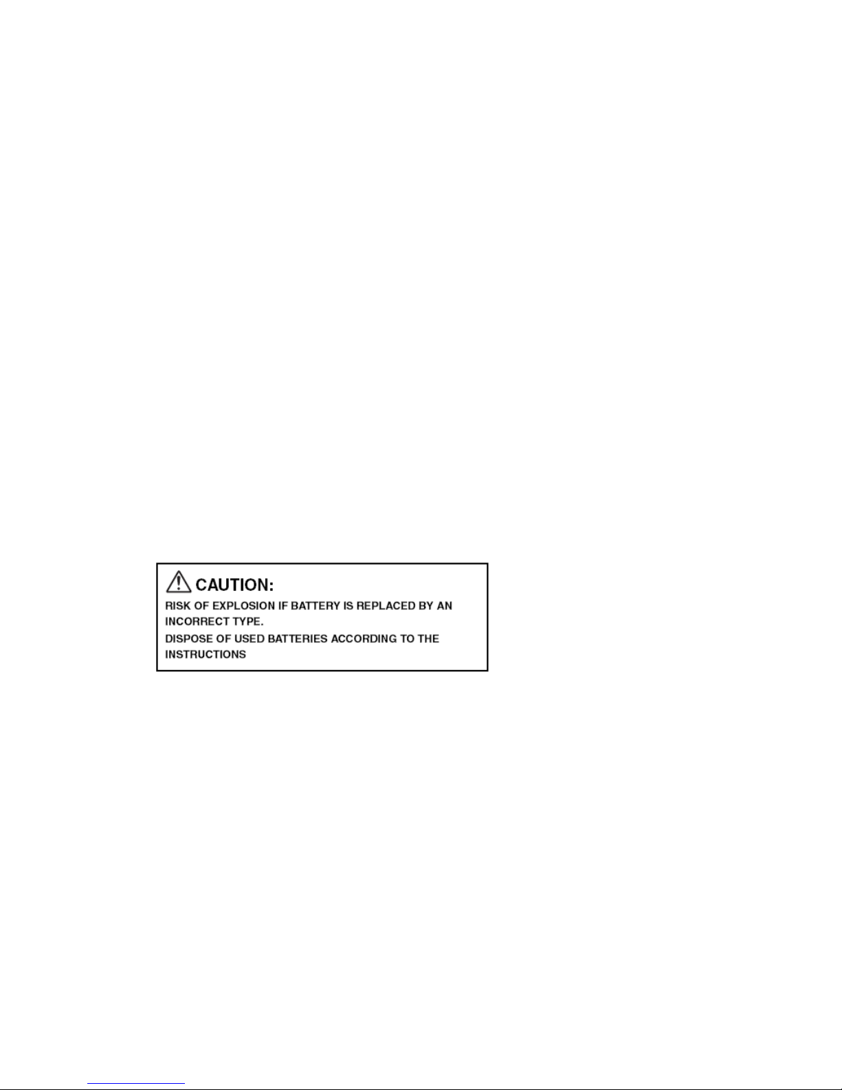
CAUTION
Danger of explosion if battery is incorrectly replaced.
Replace only with the same or equivalent type recommended by the manufacturer.
Discard used batteries according to the manufacturer’s instructions.
This symbol indicates the presence of important operating and
maintenance (servicing) instructions in the literature accompanying the
product.
This symbol indicates the presence of uninsulated ”dangerous voltage”
within the product’s enclosure that may be of sufficient magnitude to
constitute a risk of electric shock to persons.

3
These precautions must be followed for safety reasons.
Warning
Do not use if the unit emits smoke, strange sounds are heard or odor is emitted.
- Continued use may cause electrocution and/or fire. Immediately remove the power plug from
the outlet. Once the unit stops emitting smoke, consult the dealership where this unit was
purchased or factory shop for repairs.
- Do not attempt repairs on your own.
Make sure the power cable is not damaged.
- Always use the power cable supplied with the unit.
- Do not place heavy objects on the power cable or place the power cable near heating
equipment. Also, do not bend the power cable forcefully, work upon or staple it. A damaged
power cable may result in fire and/or electrocution.
- Should the power cable become damaged it must be replaced by the dealership where this unit
was purchased or factory shop.
Make sure there is no dust accumulation on the power plug or the outlet.
- Dust accumulation may result in a short-circuit and heat generation and cause fire.
- Be especially careful when using an outlet situated in a room exposed to high humidity,
condensation and/or dust, or in a kitchen.
- Periodically remove the power plug from the outlet and clean any dust and dirt between the plug
and the outlet.
Caution when connecting the power cable
- Connect the power plug directly with the outlet. Faulty connection may result in heat generation
and cause fire.
- Do not use the power cable while it is tied in a bundle. This may result in heat generation and
cause fire.
- When using the extension cord supplied, make sure the power consumption of the connected
unit does not exceed the electrical rating of the extension cord. Higher power consumption may
result in heat generation and cause fire.
Disassembly prohibited
- Do not place your hand inside this unit as this may cause fire and/or electrocution.
- Consult the dealership where this unit was purchased or factory shop for diagnostics,
adjustments, and repairs.
Do not place any foreign objects inside the unit.
- Do not insert or push in any metal or combustible object through openings such as air ducts.
This may cause fire and/or electrocution.

4
- In the event that a foreign object is inside the unit, turn off and unplug the unit. Consult the
dealership where this unit was purchased or factory shop. Continued use may result in fire
and/or electrocution.
Do not place a container holding water or other liquids above the unit when it is connected to
power.
- In the event that water gets inside the unit, turn off and unplug the unit. Consult the dealership
where this unit was purchased or factory shop. Continued use may result in a fire or
electrocution.
Do not allow the unit to get wet.
- This unit is not waterproof. Do not expose the unit to water. This may cause fire and/or
electrocution. Do not use in a bath or shower room.
- In the event that the internal components have been exposed to water, turn the power off and
remove the power plug from the outlet. Consult the dealership where this unit was purchased or
factory shop. Continued use may cause electrocution and/or fire.
Do not use during thunder/thunder storms.
- Do not use during thunder/thunder storms. Never touch the connection cable during
thunder/thunder storms. This may cause electrocution.
Do not place in an unstable position.
- Doing so may cause accidents and/or breakdowns through falling or toppling.
- In the event that the unit has been dropped or the casing has been damaged, turn the power off
and remove the power plug from the outlet. Consult the dealership where this unit was
purchased or factory shop. Continued use may cause electrocution and fire.
Do not expose to shock or vibration.
- Stored data may be damaged or lost through hard-disk breakdowns caused by shock/vibration.
Do not use this unit in areas where it is exposed to the possibility of explosion.
- Do not use this unit in areas where explosive and/or flammable gases are present. This may
cause fire and/or explosion.
For pluggable equipment, the socket-outlet shell be installed near the equipment and shall be
easily accessible.
Caution
Do not pull on the power cable when removing the power plug from the outlet.
- Hold the power plug when disconnecting the power cable from the outlet. Pulling on the power
cable from the outlet. Pulling on the power cable may damage the cord. This may cause fire
and/or electrocution.
Do not touch the power plug with wet hands.
- Doing so may result in electrocution.
Do not sit on.

5
- Doing so may cause the unit to fall, be damaged and/or result in injury.
Make sure the cables are connected properly.
- Connect and install the power cable and connection cable very carefully. Tripping over the cable
may result in the unit capsizing or falling and cause injury.
Do not place heavy objects on connected units.
- Doing so may affect the stability of the unit and cause it to fall which may result in injury. Doing
so may also damage the unit depending on the weight of the object.
Shipment and portability
- Never move this unit while the power is turned on.
- When shipping, remove the power plug from the outlet, confirm that the connection cable has
been removed, and store in original packaging. Ship using a method that causes the least
amount of shock and/or damage to this unit. Also, do not drop this unit.
Maintenance when the unit is going to remain unused for long periods of time
- Remove the power plug from the outlet when the unit is going to remain unused for long periods
of time.
Cleaning the internal components
- Consult the dealership where this unit was purchased or factory shop for cleaning internal
components. Leaving the unit unused for long periods of time may attract duct to the internal
components, which in turn may cause fire and/or breakdowns.
Do not block the cooling fans or air ducts.
- This unit it equipped with air ducts and cooling fans in order to assist the ventilation of hot air
produced by the hard disk drive. Placing covers, placing in a case, or placing inside bookcases
may cause heat build up, and may result in fire and/or electrocution.
- When the unit is set up in a rack, leave open space on all sides.
. Leave 5 cm or more of space above and below.
. Leave 10 cm or more of space on both sides and on the rear.
Do not expose to extreme temperatures or humidity changes.
- Do not place in areas where the unit will be exposed to extreme temperatures (±10 degrees C
per hour) or humidity changes.
Points on unit positioning
- This unit is constructed using precision electronic parts. Avoid placing it in areas described
below as this may cause faulty operation and/or breakdowns.
. In direct sunlight
. In places exposed to water
. In the vicinity of cooling and heating units or humidifiers
. Near the air conditioner where the unit is exposed to cool air
. Dusty areas
. Areas that contain fire hazards
. In the vicinity of volatile substances
6
. Areas where the unit will be exposed to constant vibration (in trains, cars, etc.)
Cautionary points on condensation
- Droplets may form on the outside when very cold water is poured into a cup. In the same way,
droplets may form around the internal components of his unit. This is called condensation.
- Do not use this unit if condensation has formed. Using this unit while condensation is formed
may cause breakdowns. In the event of sudden sharp temperature changes, turn off the power
and do not use this unit until the temperature of the room where it is positioned stabilizes (about
2 hours). Condensation will not occur while the power is turned on.
- When condensation is likely to occur… Use the unit after turning the power off and leaving it for
1~2 hours.
Back up battery
- This unit has got a built-in lithium battery used to back up the clock function. The battery
continues to operate the clock even when there is a power disruption.
- The life expectancy of the battery is approximately 2 years. If the battery runs out or leaks, the
clock resets when the power is turned off.
- Battery fluid leaks
. In the event that the battery fluid has leaked rinse hands/clothes thoroughly with water.
. Loss of eyesight may result if battery fluid enters the eyes. Do not rub the eyes. Immediately
rinse with clean water and consult a physician.
- When disposing of this unit
. Consult the dealership where this unit was purchased for information concerning the disposal
of the lithium battery.
Warning
Installation and servicing should be performed only by qualified and experienced personnel.
Turn off the power of the DVR when connecting cameras, audio or sensor cables.
The manufacturer is not responsible for any damage caused by improper use of the product or failure to
follow instructions for the product.
The manufacturer is not responsible for any problems caused by or resulting from the user physically
opening the DVR for examination or attempting to fix the unit. The manufacturer may not be held liable for
any issues with the unit if the warranty seal is removed.
Warranty for Critical Parts
HDD, Battery and ATX Power: 2 years (25℃ environment)
Cooling Fan: 3 years (25℃ environment)
7
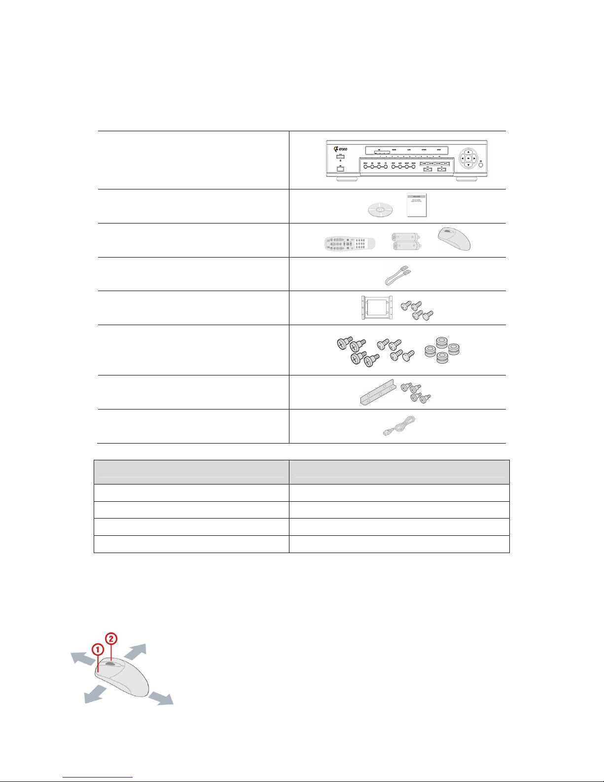
Product Components
The package contains the main unit and its components as specified below. When you purchase the unit,
Please check to ensure the components specified below are included.
DVR Set
Client Software CD, User Guide
/
Remote Control , Battery1.5V, Mouse
/ /
HDD SATA data cable
HDD mounting bracket & Screw
HDD bracket fixing screw
Rack Mount (2EA)
Power Cable (110V or 220V)
Items Quantity
HDD SATA Data Cable 4 EA
HDD Mounting Bracket 2 EA
HDD Mounting Bracket Screw 16 EA
Rack Mount Bracket 2 EA
Basic function of the MOUSE
① : Left button: SELECT function
② : Wheel: MOVEMENT function on a drop-down menu

8
Mounting the HARD DISK
1. Remove the unit’s cover. 2. Fix the supplied rubber pads to the
supplied HDD mounting bracket. Then fix
the hard disk to the mounting bracket
using the supplied screws (A).
3. Connect the unit’s power cable (B) and the supplied S-ATA cable (C) to the hard disk. Then
fix the hard disk to the unit using the supplied HDD fixing screws (D).

9
Compatible HDD Models
Seagate ST32000542AS (Barracuda LP) 2 TB 5900 RPM 32 MB
Seagate ST31000340SV (Surveillance) 1 TB 7200 RPM 32 MB
Seagate ST3100528AS (Barracuda) 1 TB 7200 RPM 32 MB
Seagate ST3500830SCE 500 GB 7200 RPM 8 MB
Seagate ST3500418AS (Barracuda) 500 GB 7200 RPM 16 MB
Seagate ST3500410AS (Barracuda) 500 GB 7200 RPM 16 MB
Seagate ST3250410AS (Barracuda) 250 GB 7200 RPM 16 MB
Seagate ST3250310SV (Surveillance) 250 GB 7200 RPM 8 MB
Seagate ST3250318AS (Barracuda) 250 GB 7200 RPM 8 MB
Seagate ST3160815AS (Barracuda) 160 GB 7200 RPM 8 MB
HITACHI HDS722020ALA330 2 TB 7200 RPM 32 MB
HITACHI HDS721010KLA330 1 TB 7200 RPM 32 MB
HITACHI HDT721010SLA360 1 TB 7200 RPM 16 MB
HITACHI HDS721010CLA332 1 TB 7200 RPM 32 MB
HITACHI HDS721050CLA362 500 GB 7200 RPM 16 MB
HITACHI HDP725050GLA360 500 GB 7200 RPM 16 MB
HITACHI HDS721032CLA362 320 GB 7200 RPM 16 MB
HITACHI HDS721025CLA382 250 GB 7200 RPM 8 MB
HITACHI HDT721025SLA380 250 GB 7200 RPM 8 MB
HITACHI HDP725025GLA380 250 GB 7200 RPM 8 MB
Western Digital WD20EADS 2 TB 7200 RPM 32 MB
Western Digital WD10EACS 1 TB 7200 RPM 16 MB
Western Digital WD5000AACS 500 GB 7200 RPM 16 MB
Western Digital WD2500AAKS 250 GB 7200 RPM 16 MB
NOTICE
The brands and models of all HDD should be the same. If the brands and models of the HDD are different, the DVR
may not recognize HDD or malfunction.
Storage Estimation
HDD
Capacity
Super High Standard Economy
Hour(s) Hour(s) Hour(s) Hour(s)
250GB 23 Hours 1 Days 5 Hours 2 Days 10 Hours 4 Days 20 Hours
500GB 2 Days 2 Days 13 Hours 5 Days 1 Hours 10 Days 2 Hours
1TB 4 Days 3 Hours
5 Days 4 Hours 10Days 8 Hours 20 Days 16 Hours
2TB 8 Days 9 Hours 10 Days 11 Hours 20 Days 21 Hours 41 Days 19 Hours
Recording Condition: 4CH * 1280X720* 30fps * Continuous

10
Booting the DVR and Basic Time Setting
1. During the first start up, the following message will be displayed.
2.
Setting Daylight Saving Time
If the DVR is to be set Day Light Saving Time and be synchronized NTP (Network Time Protocol), Take next steps.
1. Enter the SETUP mode. The default Password is “1111”.
2. Go to SETUP>SYSTEM>SET DATE & TIME
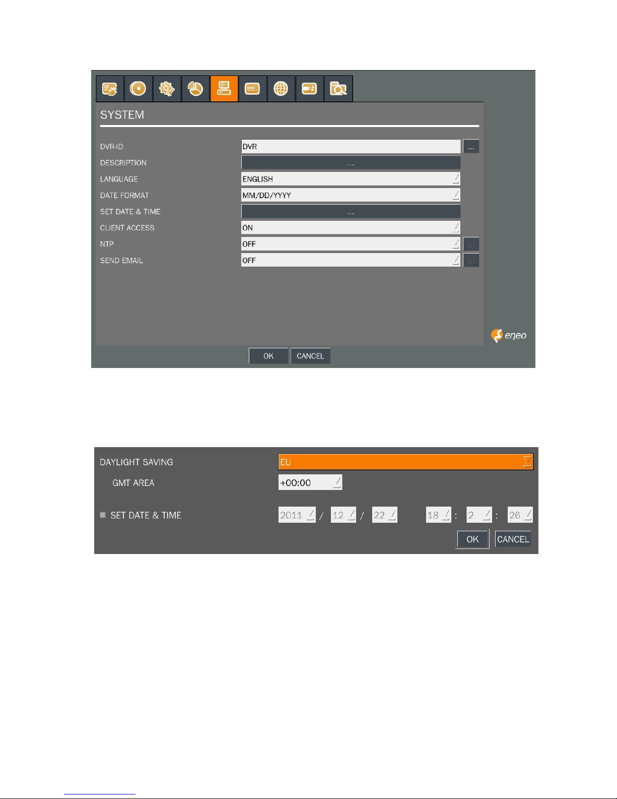
11
3. Select DAYLIGHT SAVING.
Setting NTP (Network Time Protocol)
1. When the DVR is connected with internet and the DVR need to be syncronized with NTP (Network Time
Protocol), set SETUP>SYSTEM>NTP ON.
2. Select proper TIME ZONE time.
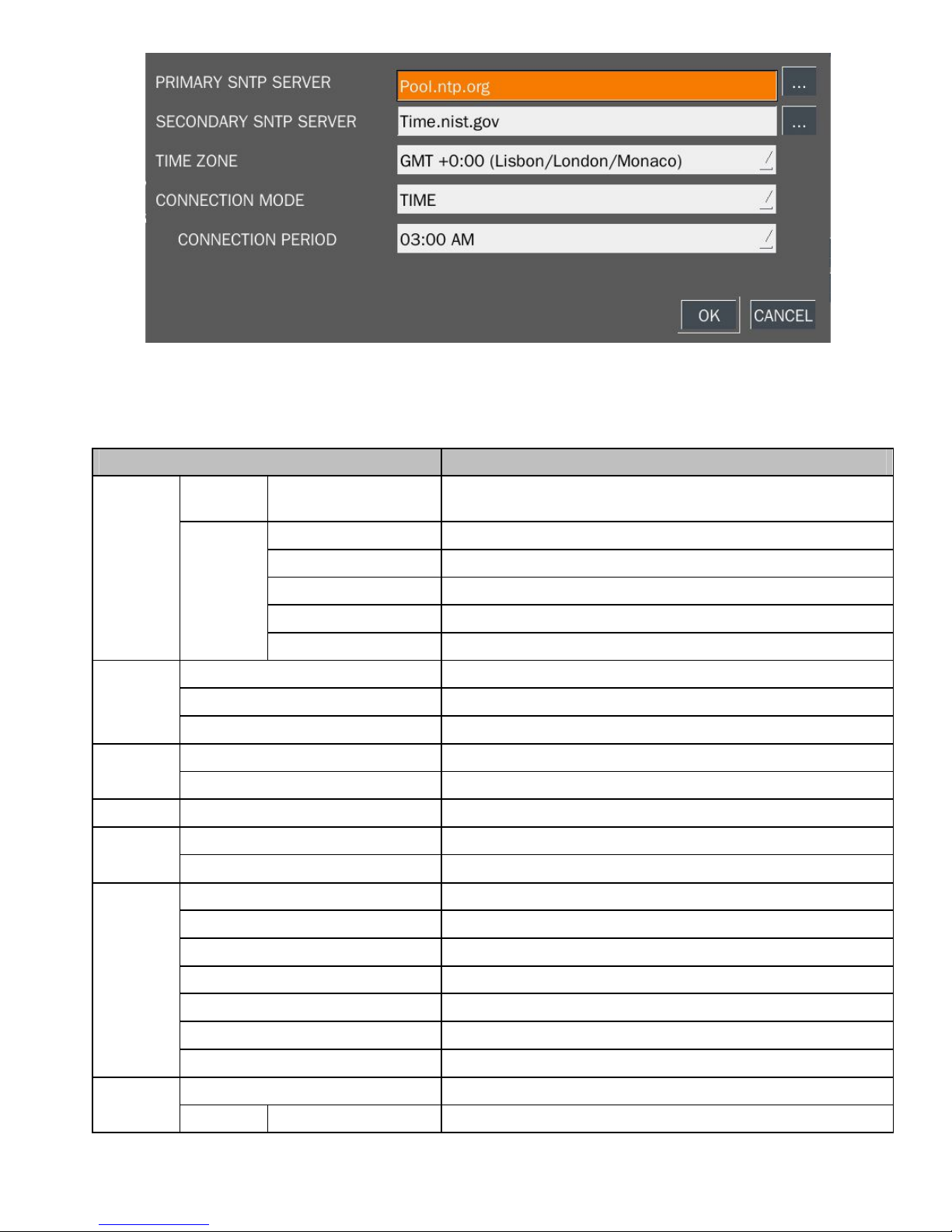
12
NOTE: If you want the unit to automatically synchronize the local time, the Time Zone must be
properly set according to your local Time Zone.
Specification
ITEM HDR-4004AM1.0
Video
Input Channel Input Level 4CH HD-SDI (720p25/30/50/60, 1080p25/30, 1080i50/60)
Output
Main Monitor HDMI (Max. 1920x1080)
Sub Monitor VGA (Max. 1920x1080)
HD-SDI Monitor SDI (1920x1080 60i)
CVBS
SPOT
Audio
Input 4CH Line Input
Output 1CH Line and HDMI Output
Audio Codec G.711
Alarm
Sensor Input 4CH, NC/NO Selectable
Alarm Out 1CH out by Sensor, Motion and Video Loss
Operation
PentaPlex Live/Record/Playback/Backup/Network
Live
Digital Zoom Zoom-in of specific area
Channel Sequence 3 ~ 60 seconds Auto
Recording
Compression H.264
Resolution Up to 1920x1080
Recoding Quality Grade 5 Levels
Recording Mode Continuous, Schedule, Motion, Sensor, Manual
Motion Detection Setup by Grid
Pre Recording Min. 15 seconds and Max. 20 minutes
Post Recording 10 ~ 60 seconds
Playback
Digital Zoom Zoom-in of specific area
Speed FF x1/4, x1/2, x2, x4, x8, x16 and x32

13
FR x2, x4, x8, x16 and x32
Search Mode Timeline, Event, Archive, Log, Specific Time
Backup
File Format JPEG/Proprietary Format
Media USB/External HDD/DVD/Network
Built-in Viewer Yes
Network
Dual Streaming for Live 1280x720/640x360 120/100fps
Playback H.264 HD 120/100fps
Streaming RTP/RTSP/RTCP
Protocols HTTP, DDNS, NTP, SMTP
Storage
HDD
Interface SATA, e-SATA
Max. Capacity of HDD 2TB
Max. Internal HDDs 4EA
External Storage 2 e-SATA for RAID
File system Self-developed, Reliable and Stable Filesystem
S.M.A.R.T HDD Error Check and Reporting
User
Interface
Menu Display Graphic User Interface
Input Method Front Buttons, IR Remote control, Mouse, Keyboard controller
Serial
POS 1 RS-232C
PTZ & Controller 2 RS-485, HD-SDI
Network Ethernet RJ-45, 10/100/1000Base-T, Auto MDI/MDIX
Network
Access
Web Viewer Live, Search/Playback, Backup, PTZF, Remote Setup/Upgrade
Single-site monitoring software Live, Search/Playback, Backup, PTZF, Remote Setup/Upgrade
Multi-sites monitoring software Live, Search/Playback, Backup, PTZF, Remote Setup/Upgrade
Features
DST (Daylight Saving Time) Yes
Internal Beep By Video Loss, HDD Error
Multi Language Yes (more than 20 languages)
Software Upgrade By USB, Network Remote Upgrade
NTP Yes
Watermarking Yes
3G Mobile iPhone, Android, Blackberry
General
Operation Condition 0~40C, Humidity 20~80%
Power AC 100~120V/200~240V, 50/60Hz, 280W
Net Weight (Gross Weight) 6.6 kg (8.8 kg) / 14.6 lbs (19.4 lbs)
Unit Dimension (W x D x H) 432mm x 430mm x 98mm (17.00" x 16.92" x 3.86")
Specifications are subject to change without notice

14
Table of Contents
1. Name, Function and Connection .......................................................................................................... 16
1-1. Front Panel ................................................................................................................................... 16
1-2. Rear Panel ................................................................................................................................... 18
1-3. Remote control ............................................................................................................................. 19
2. Setting up the DVR .............................................................................................................................. 20
2-1. Setup – Main Screen .................................................................................................................... 20
2-2. Setup – Display Mode .................................................................................................................. 23
2-3. Setup – Recording Mode .............................................................................................................. 24
2-3-1. Recording Schedules ................................................................................................................ 25
2-4. Setup – Device Mode ................................................................................................................... 27
2-4-1. ALARM-OUT ............................................................................................................................. 28
2-4-2 Controller & PTZ Setup .............................................................................................................. 29
2-4-3. Motion Zone Setup .................................................................................................................... 30
2-5. Setup – Storage Mode .................................................................................................................. 30
2-6. Setup – System Mode .................................................................................................................. 33
2-7. Setup – SECURITY Mode ............................................................................................................ 36
2-8. Setup – Network Mode ................................................................................................................. 38
2-8-1. Port and Web Port ..................................................................................................................... 39
2-8-2. Network Types .......................................................................................................................... 40
2-8-2-1. DHCP ..................................................................................................................................... 40
2-8-2-2.STATIC.................................................................................................................................... 40
2-8-3. DDNS ........................................................................................................................................ 40
2-8-4. NETWORK STREAM ................................................................................................................ 41
2-9. Setup - CONFIG Mode ................................................................................................................. 42
2-10. Quick Setup ................................................................................................................................ 43
3. Saving Setup ....................................................................................................................................... 44
4. Live, Search, and Playback ................................................................................................................. 44
4-1. Live Viewing Screen ..................................................................................................................... 44
4-2. SEARCH Screen .......................................................................................................................... 46
4-2-1. TIME-LINE Search .................................................................................................................... 47
4-2-2. Event Search............................................................................................................................. 48
4-2-3. Go To First Time ........................................................................................................................ 48
4-2-4. Go To Last Time ........................................................................................................................ 48
4-2-5. Go To Specific Time ................................................................................................................... 49
4-2-6. Archive Search .......................................................................................................................... 49
4-2-7. Log Search ................................................................................................................................ 50
4-3. Play mode .................................................................................................................................... 50
5. PTZ Control ............................................................................................................................................ 52

15
6. Back up .................................................................................................................................................. 53
6-1. Still Image backup onto USB flash memory .................................................................................. 53
6-2. Video backup onto USB flash memory ......................................................................................... 54
6-3. Transferring still images or video from the ARCHIVE list .............................................................. 55
6-4. Playback of Backup Video ............................................................................................................ 56
7. Upgrading Firmware ............................................................................................................................... 56
8. Network access using the Exclusive network viewer, UMS single ........................................................... 62
8-1. PC requirements .......................................................................................................................... 62
8-2. Installing the network viewer ......................................................................................................... 62
8-3. Live monitoring mode and functions. ............................................................................................ 63
8-4. Bi directional audio ....................................................................................................................... 65
8-5. Remote search mode and functions ............................................................................................. 66
8-6. PC System configuration .............................................................................................................. 68
9. Network access using the Exclusive network viewer, UMS multi............................................................. 71
9-1. Overview ...................................................................................................................................... 71
9-2. Minimum PC requirements ........................................................................................................... 71
9-3. Installing the program ................................................................................................................... 72
9-4. Live Window ................................................................................................................................. 73
9-4-1. Main user interface ............................................................................................................. 73
9-4-2. Control buttons ................................................................................................................... 73
9-5. Search and Playback Window ...................................................................................................... 74
9-5-1. Main user interface ............................................................................................................. 74
9-5-2. Main control panel .............................................................................................................. 75
9-6. Setup of UMS Multi Client............................................................................................................. 77
9-6-1. General .............................................................................................................................. 77
9-6-2. Event .................................................................................................................................. 78
9-6-3. Record ............................................................................................................................... 79
9-6-4. OSD ................................................................................................................................... 80
9-6-5. Language ........................................................................................................................... 80
9-6-6. About .................................................................................................................................. 81
9-7. Remote Setup .............................................................................................................................. 81
9-8. Operation ..................................................................................................................................... 86
9-8-1. Addition, Delete, and modify of DVR sites .......................................................................... 86
9-8-2. Connect and Disconnect .................................................................................................... 88
9-8-3. Still-image capture during Live ........................................................................................... 89
9-8-4. Recording video on local PC during Live ............................................................................ 90
9-8-5. Local Playback and Remote Playback................................................................................ 91
9-8-6. AVI Backup during playback ......................................................................................................... 93
10. Network – By an web-browser viewer ................................................................................................... 95
16
APPENDIX: How to connect network .......................................................................................................... 99
A. How to set IP address of the DVR and open TCP port of the router? ............................................ 99
B. How to access DVR from Remote PC? ...................................................................................... 101
C. How to access DVR with iPhone? ............................................................................................... 104
D. How to access DVR with Android? .............................................................................................. 106
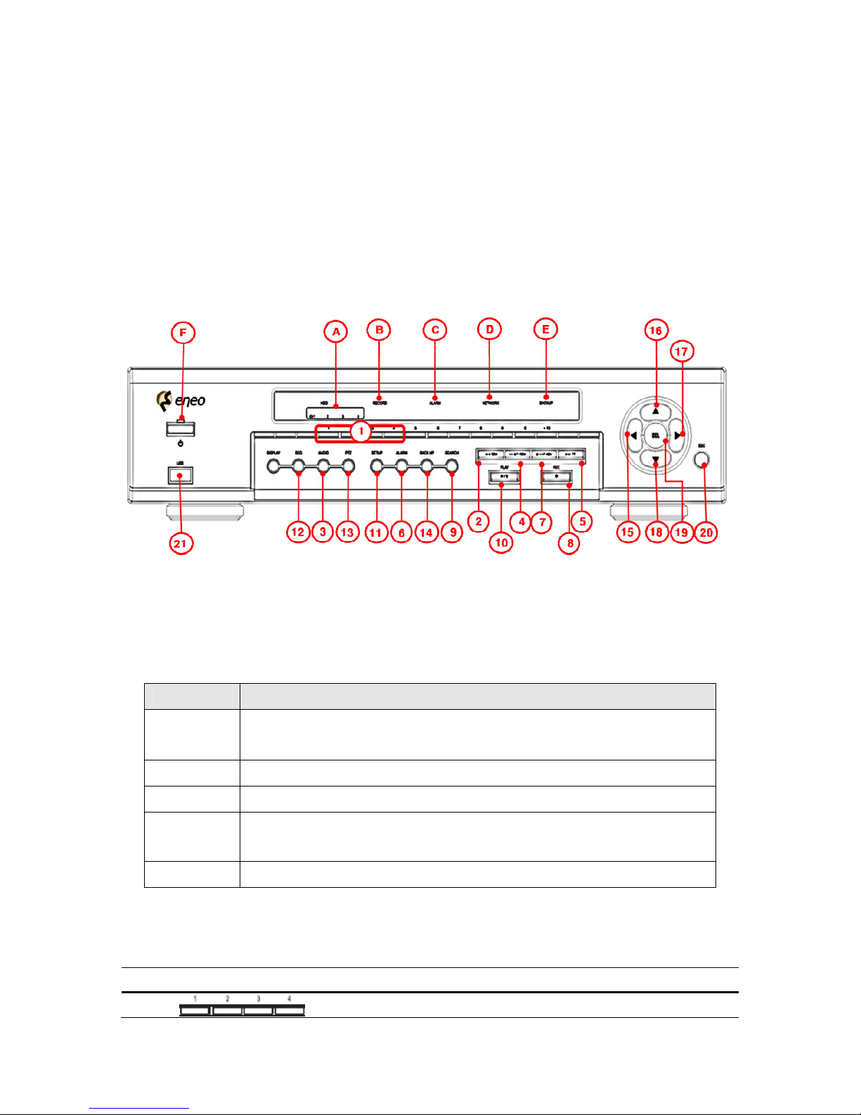
1. Name, Function and Connection
1-1. Front Panel
The following information will help you to operate the front panel controls.
Figure 2.1.1. Front panel
Indication Lights
Name Description
POWER
Indication light is on when power is applied to the system.
Green – Power On, Orange – Power Off
HDD Indicates that the system is accessing the hard disk.
ALARM Indicates that sensor(s) is/are triggered or motion is detected.
NETWORK
Indication light is on when client is connected to the system through the
network.
CH 1, 2, 3, 4 Indication light is on when the channel is recording.
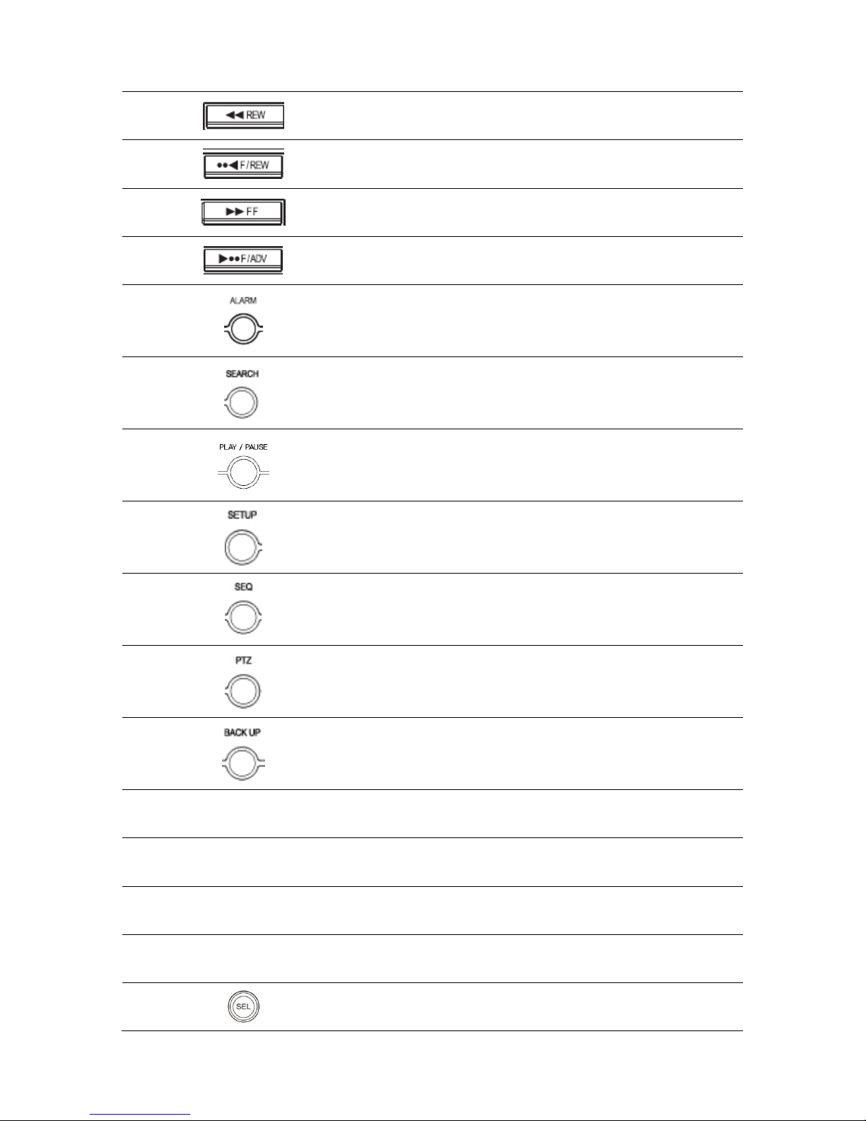
Front Panel Buttons
NO Name Description
1
Channel Keys (1 to 4)
17
2
Press to rewind the footage in playback mode.
3
Jump/Step backward. In playback mode, the playback
position moves 60 seconds backward.
4
Press to fast forward the footage in playback mode.
5
Jump/Step forward. In playback mode, the playback
position moves 60 seconds forward.
6
Set the alarm output mode. (On or Off)
7
Press to go to SEARCH menu in live display mode.
8
Press to play/pause the footage in playback mode.
9
Press to enter SETUP menu.
10
Enable/disable the automatic sequence of display of
channels in full screen, quad, 9-split display mode.
11
Press to control Pan/Tilt/Zoom operations.
12
Press to capture video in jpeg format in live or playback
mode.
13
◀(LEFT)
Press to move left or to change the values in Setup mode.
It is also used as the number 4 when entering password.
14
▲(UP)
Press to move up the menu in Setup mode.
It is also used as the number 1 when entering password.
15
▶(RIGHT)
Press to move right or to change the values in Setup mode.
It is also used as the number 2 when entering password.
16
▼(DOWN)
Press to move down the menu in Setup mode.
It is also used as the number 3 when entering password.
17
Press to select desired menu item or to store the setup
value.
18
18
Press for temporary storage of the changed value or to
return to the previous menu screen.
19
Press to start or stop manual recording.
20
Display Key for split the channel screen from single to all.
21 USB Port To archive still-image or video into a USB memory or
upgrade firmware with USB memory stick, connect a USB
memory to the USB terminal.
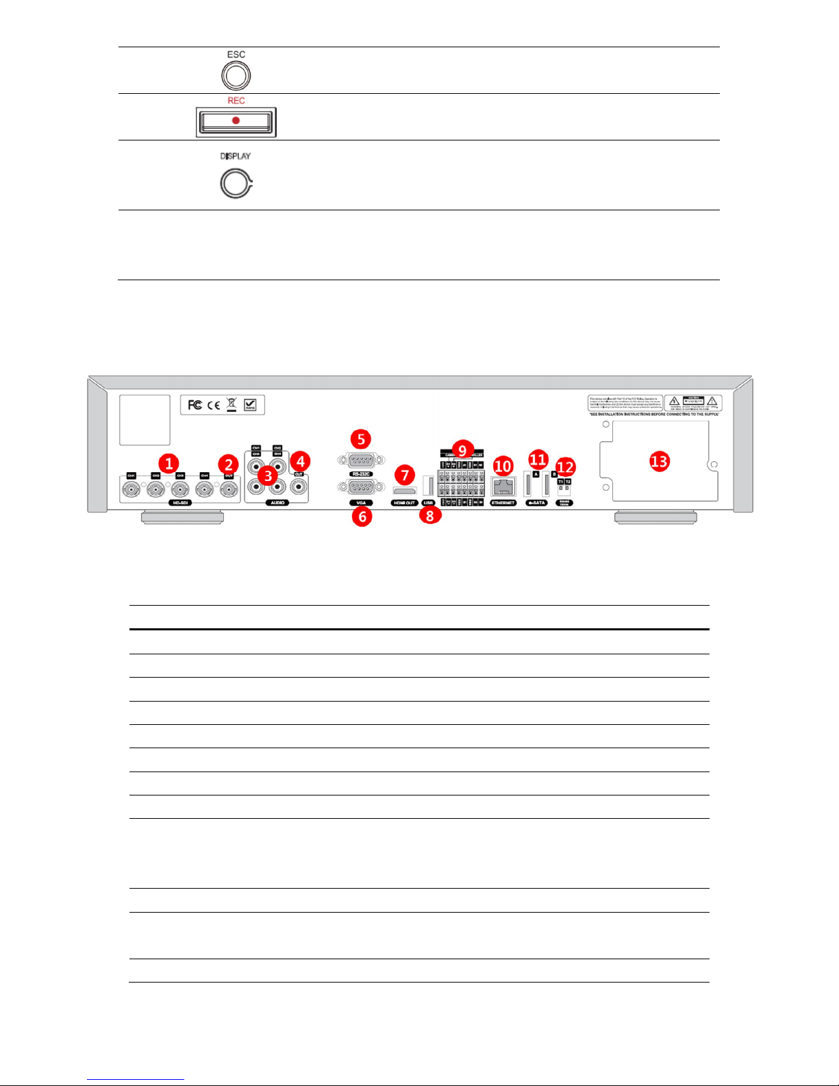
1-2. Rear Panel
Figure 2.2.1. Rear Panel
Table 2.2.1. Rear panel connections
NO Connection Purpose
1
VIDEO IN 4 HD-SDI connectors for video input.
2 SDI OUT HD-SDI connectors for video output.
3 AUDIO IN 4 connectors for audio input.
4 AUDIO OUT 1 connector for audio output.
5 RS-232 POS Interface (TBD).
6 VGA Connector for VGA monitor.
7 HDMI OUT HDMI connector for video output
8 USB Port Connector for Mouse or Backup
9 D1/D2
A1, B1
S1, S2, S3, S4
1st and 2nd ports for RS-485. (for camera and controller)
Alarm output connector for alarm device
4 Connectors for Sensor device connection
10 ETHERNET RJ-45 connector for network function
11 E-SATA 2 e-SATA ports to archive still-image or video into a External
Storage HDD .
12 TERMINATE RS-485 termination switch for 1st and 2nd.

19
13 POWER SOCKET
(Input Voltage)
Connect for AC110V~250V
(Select Input voltage according to local electricity standard)
1-3. Remote control
① ID: When a remote control ID number is set in DVR, press it before
number.
② REC: To start and stop manual recording.
③ Number: To select channel (1, 2, 3, & 4) or to enter DVR ID number.
④ --◀ (F/REW):
During playback - To move the playback position 60 seconds backward.
During pause - To move the playback position 1 frame backward.
⑤ ▶-- (F/ADV):
During playback - To move the playback position 60 seconds forward.
During pause - To move the playback position moves 1 frame forward.
⑥ ◀◀ (REW): To rewind the footage at 1x, 2x, 4x, and more speed
during playback.
⑦ ▶/II (PLAY/PAUSE): To play or to pause the footage in playback mode.
⑧ ▶▶ (FF): To fast forward the footage at 1x, 2x, 4x, and more speeds
during playback.
⑨ Control button: Press to move the menu items or select channel.
⑩ SETUP: To launch SETUP menu.
⑪ SEARCH: To go to the search menu.
⑫ ESC: During setting - To return to previous menu screen.
During playback - To exit from playback
System Lock – to lock a system when pressing ESC button for
5 seconds.
System Unlock – to unlock a system when pressing ESC button
for 5 seconds.
⑬ BACKUP: To start operations of backup in live or playback mode. (The
same function button as CAPTURE on the front panel of DVR in case of New
Entry and Mighty series)
⑭ SEQ: To start auto sequencing of the screen in full screen mode.
(Toggle)
20
2. Setting up the DVR
The following sections detail the initial setup of a DVR.
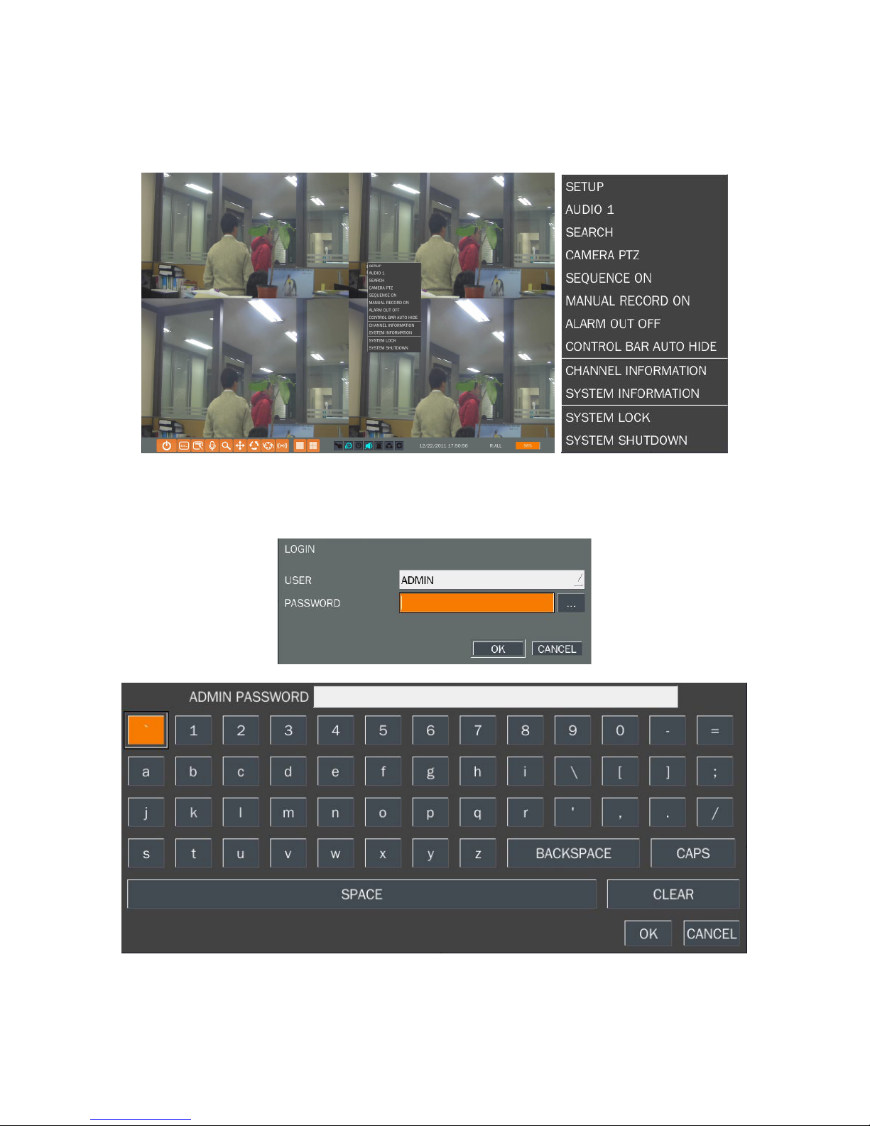
2-1. Setup – Main Screen
To enter the setup menu, select MENU and SETUP on the screen using the mouse or press the SETUP
button on the front panel. Then select a user type. User can select one of user types (ADMIN, USER1,
USER2, USER3) using the control button (◀ ▲ ▶ ▼) on the front panel and press SEL button.
Input the password by front key panel, mouse or remote controller.
Use the Virtual Keyboard when you use front key and mouse. The factory default password is 1111.
It is highly recommended to assign a new password to protect the system. User can assign a new
password in SECURITY setup menu.

21
HD VIDEO INPUT: Display a channel, total time, elapsed time, error count, active pixels, total pixels, active
lines, total lines and frame rate of HD channel (9~10).
CONTROL BAR AUTO HIDE: Set to hide automatically or display continuously a control bar on the bottom
side in a Live mode.
CHANNEL INFORMATION: Display a channel number, channel name, resolution, frame rate, quality and
recording type of each channel.
SYSTEM INFORMATION: Display a software version, storage size, network type, IP address, MAC
address, DDNS status, DVR ID and remote controller ID of the system.
SYSTEM LOCK: To lock the system, user input a password. To unlock the system, please press ESC
button for 5 seconds on a front panel or a remote control. You can also unlock the system when pressing
LOCK icon on the screen using a mouse control. Then, the system will ask a password.
Table 2.1.1. Setup menu tree
DISPLAY
– OSD
– OSD CONTRAST
– SEQUENCE
– SEQUENCE-DWELL TIME
– CHANNEL
- NAME
- COVERT
– VIDEO OPTION (HDMI/VGA)
RECORD
– CHANNEL
- RESOLUTION
- FRAME RATE
- QUALITY
- RECORDING
- SENSOR RECORDING
- PRE RECORD
- POST EVENT RECORD
- AUDIO
- SCHEDULE
DEVICE
– ALARM OUT
– CONTROLLER & PTZ
– CHANNEL
- MOTION ZONE

22
- MOTION SENSITIVITY
– KEY TONE
– REMOTE CONTROL ID
– SENSOR
- TYPE
STORAGE
– OVERWRITE
– DISK FORMAT
– DISK INFO
– RECORDING LIMIT
- RECORDING LIMIT DAYS
– S.M.A.R.T
SYSTEM
– DVR-ID
– DESCRIPTION
– LANGUAGE
– DATE FORMAT
– SET DATE & TIME
– CLIENT ACCESS
– NTP
– SEND EMAIL
SECURITY
– USER AUTHENTICATION
– USER PASSOWRD
– AUTHORITY OF PLAYBACK
NETWORK
– PORT
– WEB PORT
– NETWORK TYPE (DHCP, STATIC)
– DDNS
– NETWORK STREAM
CONFIG
– SAVE SETUP TO A USB
– LOAD SETUP FROM A USB
– LOAD DEFAULT
– LOAD FACTORY DEFAULT
QUICK SETUP
– USE QUICK SETUP
– CUSTOMER SETTINGS
– DUAL STREAM
23
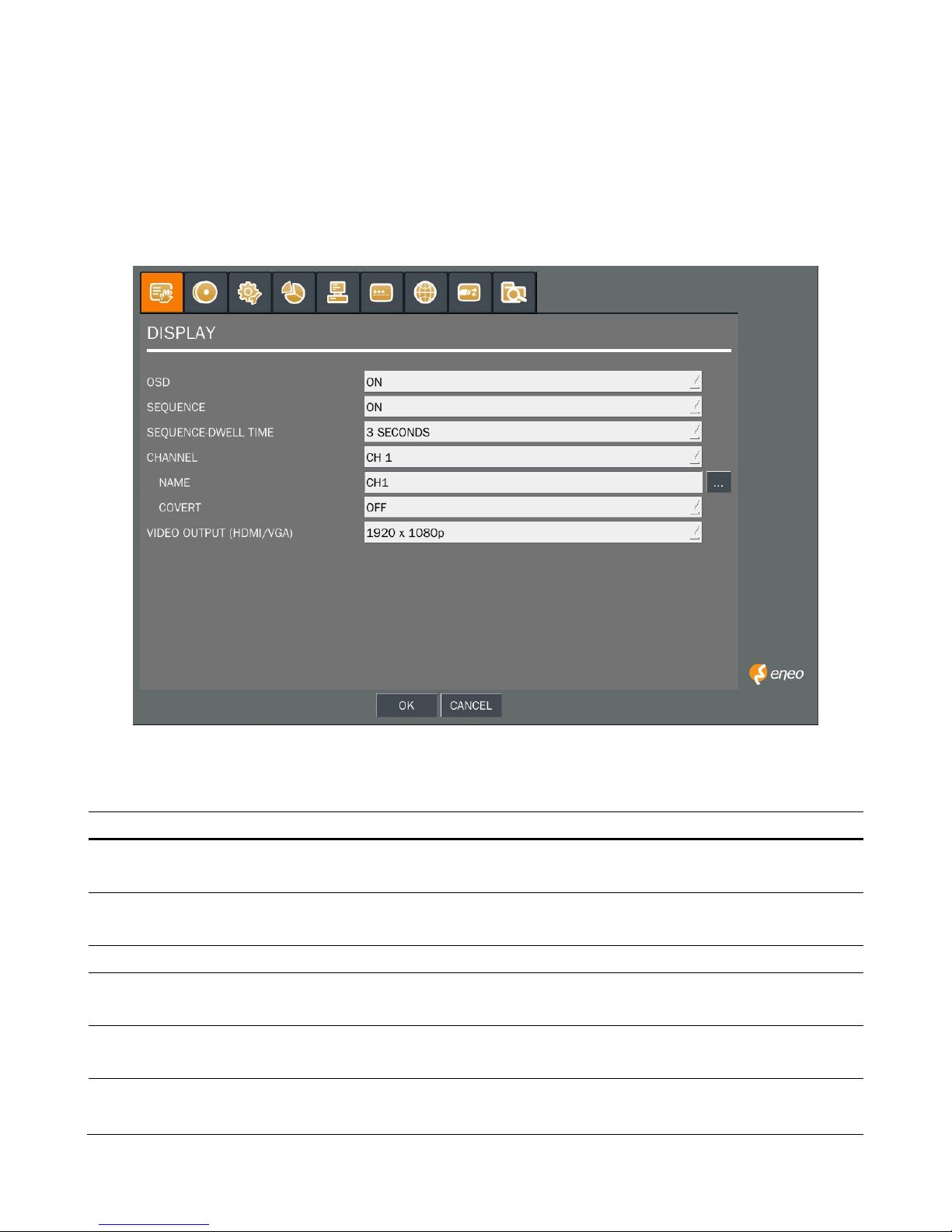
2-2. Setup – Display Mode
Press the SETUP button and enter the password. The setup menu is displayed as picture below. Select
DISPLAY icon and press SEL button to enter the setup menu item. Navigate through the menu items using
the control button (◀ ▲ ▶ ▼) and change the value of the menu item using the control button
(◀ ▲ ▶ ▼). To return to setup menu screen, press the ESC button.
Figure 2.2.1. Display mode setup screen
Table 2.2.1. Menu items in DISPLAY mode setup
Item Description
OSD
Enable/disable on-screen-display.
Select ON: show it on the screen, Select OFF: Disappear on the screen.
OSD
CONTRAST
Set the visibility level of the On Screen Display (OSD).(50-100)
SEQUENCE Enable/disable sequential display of video in full screen mode.
SEQ-DWELL
TIME
Set the dwell time of each, single channel display in sequential display mode
(3~60seconds)
CHANNEL
Select a channel for applying the following settings using the control button (◀ ▲ ▶
▼). Press SEL button to change the channel.
NAME Set the channel name. Press SEL button and set the channel name and select OK using
the control button (◀ ▲ ▶ ▼).
24
COVERT Enable/disable display of the video channel in live display mode.
VIDEO
OUTPUT
(HDMI/VGA)
Select a video output type for HDMI/VGA. (720p 50Hz, 720p 60Hz, 1080i 50Hz, 1080i
60Hz, 1080p 50Hz, 1080p 60Hz). Default value is 720p 60Hz. If the monitor doesn’t
support some output type, it would be returned to the previous value.
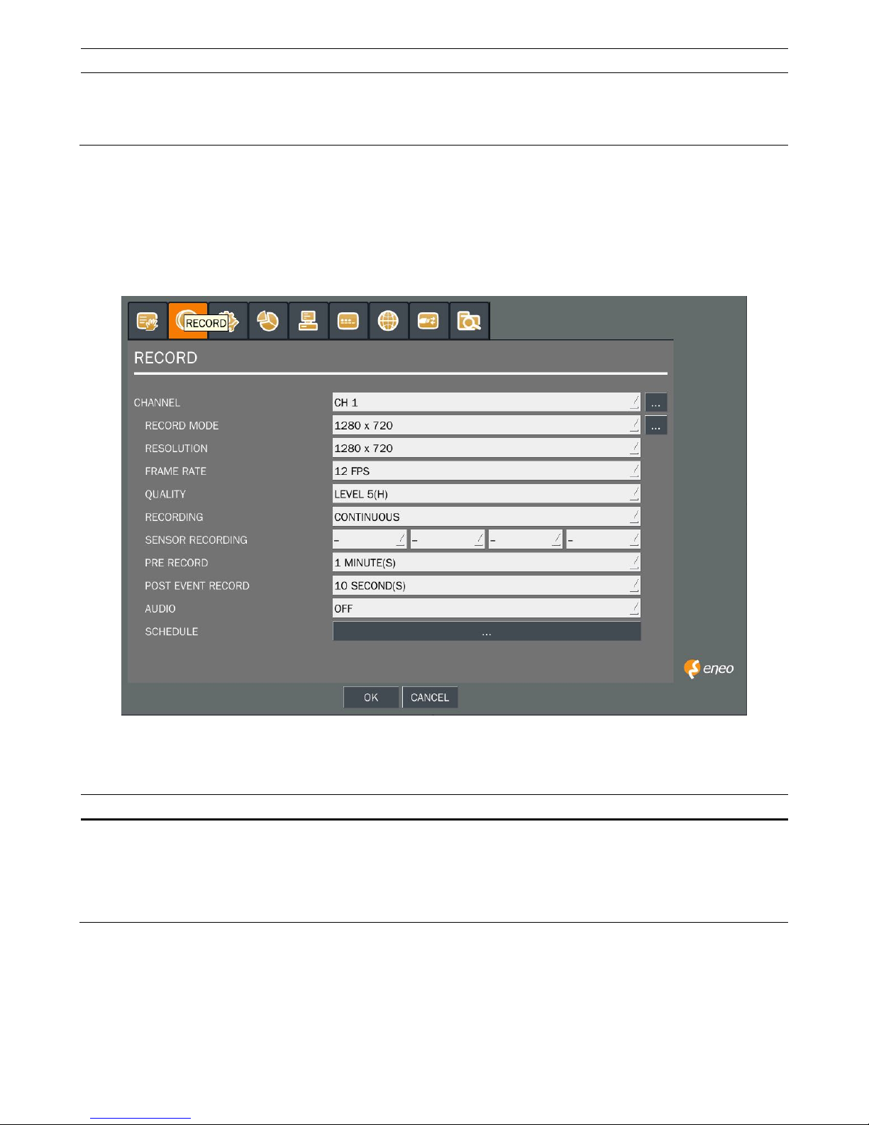
2-3. Setup – Recording Mode
Press the SETUP button and enter the password. The setup menu is displayed as picture below. Select
RECORD icon and press SEL button to enter the setup menu item. Navigate through the menu items using
the control button (◀ ▲ ▶ ▼) and change the value of the menu item using the control button (◀ ▲ ▶
▼). To return to setup menu screen, press the ESC button.
Figure 2.3.1. Recording mode setup screen
Table 2.3.1. Menu items in Recording mode setup
Menu item Description
CHANNEL
Select a channel for applying the following settings using the control button (◀ ▲ ▶
▼). Press SEL button to change the setting value of all channels at once. Once you
select an item, then press SEL to set value for all channels.
Use virtual keyboard for all setting on one screen as you want as bellow picture.
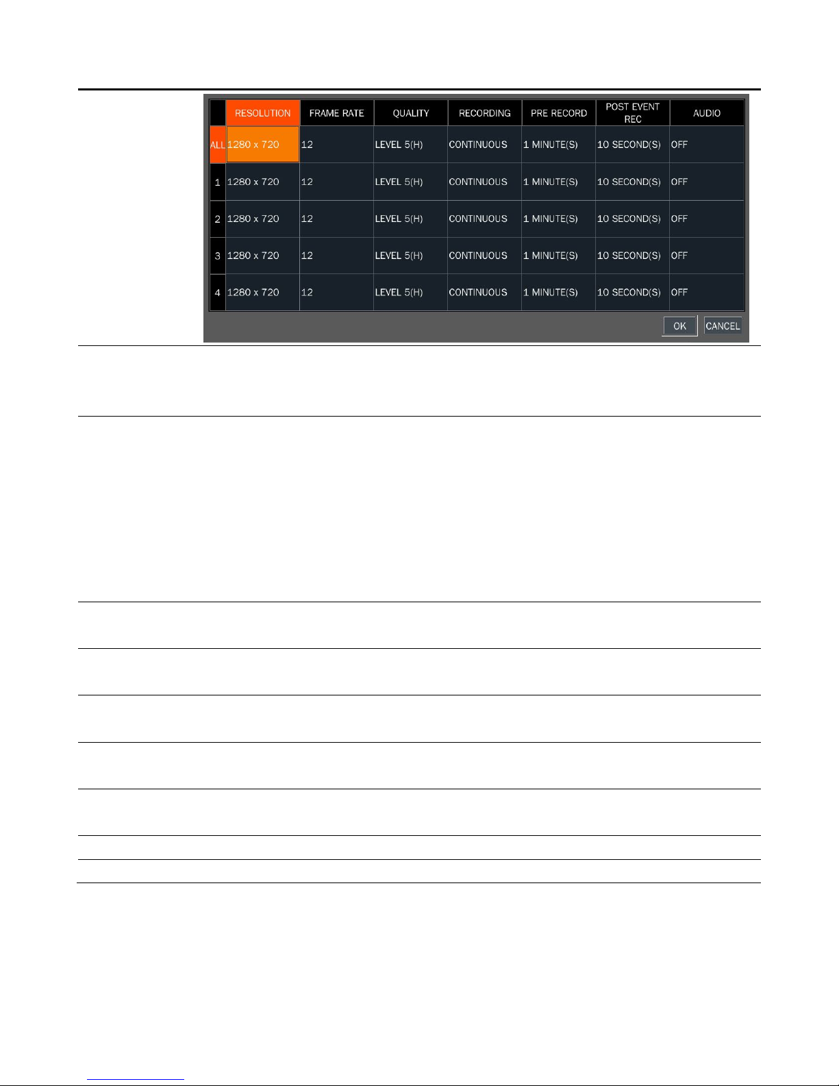
25
RESOLUTION Set the resolution for the specified channel: 1920x1080, 1920x540, 1280x720 and
640x360. You can see the 1920x1080 and 1920x540 menu when 2M HD-SDI camera is
connected.
FRAME RATE Set the frame rate for the specified channel. The sum of the frame rate values from
each channel cannot exceed the maximum frame rates for a specific recording
resolution.
Typical values of the maximum frame rate for video are Total 1080p@60fps or
720p@120fps.
* It is possible to use 1080p camera and 720p camera at the same time. Please
note that the system has to be booted after connecting all cameras on the
system.
QUALITY Select the recording quality for the specified channel. Options are: Level 1 (Low), 2, 3, 4
and 5 (High)
RECORDING Assign the recording mode for each channel. Options are: Continuous, By Motion, By
Sensor, By Schedule or Disable.
SENSOR
RECORDING
Enable setting up to 4 sensors for the specified channel using the control button (◀ ▲
▶ ▼).
PRE RECORD Enable/disable pre-event recording. Pre-event recording time is 15 seconds to 20
minutes(Selectable)
POST EVENT
RECORD
Set the post event recording time duration for the specified channel. (10-30 seconds)
AUDIO Enable/disable audio recording for the specified channel.
SCHEDULE Set the recording schedule. Press SEL to go to schedule setup screen.
2-3-1. Recording Schedules
To setup a recording schedule, select SCHEDULE in the RECORD menu. Navigate through the items using
the control button (◀ ▲ ▶ ▼).
Once the channel 1 is selected, SCHEDULE-CH1 screen is displayed. Select ALL or each day using the
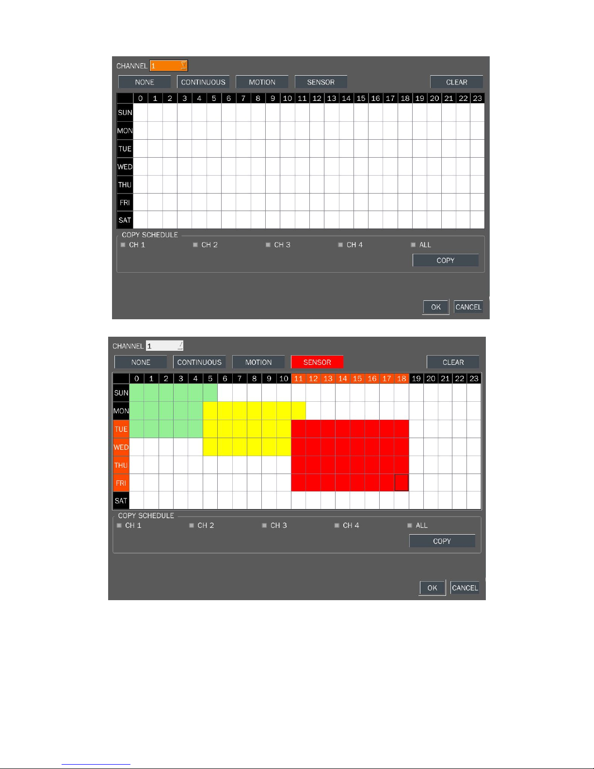
26
control button (◀ ▲ ▶ ▼) and set the recording mode using the SEL button repeatedly
.
Figure 2.3.2. Schedule recording setup screen
C: CONTINUOUS recording, when you select the color will change to Blue Color
M: MOTION recording, when you select the color will change to Yellow Color
S: SENSOR recording, when you select the color will change to Red Color
-: Does not record
27
[ALL]: Move the cursor to ALL and select a recording mode C,M or S using the SEL button to set the same
setting for every day.
[SUN to SAT]: Move the cursor to SUN to SAT and select a recording mode C,M or S using the SEL button
to set the same setting for the whole day.
[Vertical Bar “ | “]: Move the cursor to ALL and move the cursor to the specific time using the control button
(◀ ▲ ▶ ▼). And select a recording mode C,M or S using the SEL button to set the same setting.
[SEL]: The recording mode can be selected by pressing repeatedly the SEL button.
[COPY FROM] [COPY TO]: Set the channel 1 schedule and select COPY TO using the control button (◀
▲ ▶ ▼), select CH2 using the control button (◀ ▲ ▶ ▼) and press the SEL button. Then the CH1
schedule is copied to CH2.
To return to setup menu screen, press the ESC button.
The setting of the schedule recording is determined by the admin only.
2-4. Setup – Device Mode
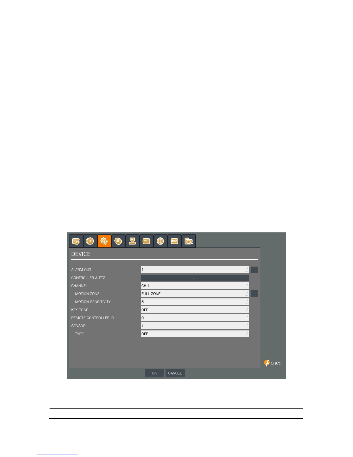
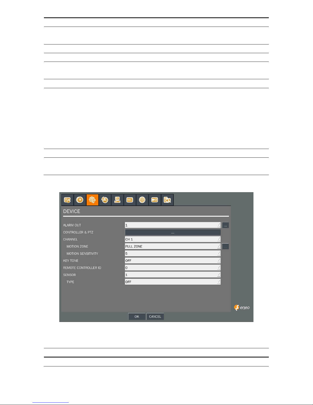
Press the SETUP button and enter the password. The setup menu is displayed as picture below. Select
DEVICE icon and press SEL button to enter the setup menu item. Navigate through the menu items using
the control button (◀ ▲ ▶ ▼) and change the value of the menu item using the control button (◀ ▲ ▶
▼).To return to setup menu screen, press the ESC button.
Figure 2.4.1. Device mode setup screen
Table 2.4.1. Menu items in Device Setup screen
Item Description
28
ALARM OUT Set the sensor, motion, and video loss for each alarm.
CONTROLLER & PTZ Set the Controller and PTZ camera speed, number, type and
ID.
CHANNEL Select specified channel for motion zone setup.
MOTION ZONE Select either Full Zone or Partial Zone for motion sensing.
MOTION SENSITIVITY Set the motion sensitivity for the specified channel.
Control the motion sensitivity from 1 to 9.
KEY TONE Enable/disable key tone.
REMOTE CONTROL ID Select an ID of remote control.
1. Select ID.
2. Press the same number as ID set in DVR on a remote
control.
3. Then icon will be displayed on Live screen of DVR that
respond to the remote control.
The options are from 00 to 99
SENSOR Select sensor NO from 1 to 4
TYPE Set the type of sensor for the specified channel. Options are:
OFF, N/O (normal open), and N/C (normal closed).
2-4-1. ALARM-OUT
Figure 2.4.2. ALARM-OUT setup screen
Table 2.4.2. Menu item in ALARM-OUT Setup screen
Item Description
ALARM OUT Select an alarm out number.
29
Available NO: 4ch (1)
SENSOR IN Enable Alarm Out by Sensor up to 4 Inputs.
MOTION ON Enable Alarm Out by Camera Motion up to 4 cameras.
VIDEO LOSS ON Enable Alarm Out by Video Loss up to 4 cameras.
ALARM DURATION Set the alarm dwell time from 5 to 60 seconds.
ERROR ALARM Set the error type for the alarm activation. The options are
OFF, ALL, HDD ERROR and VIDEO LOSS.
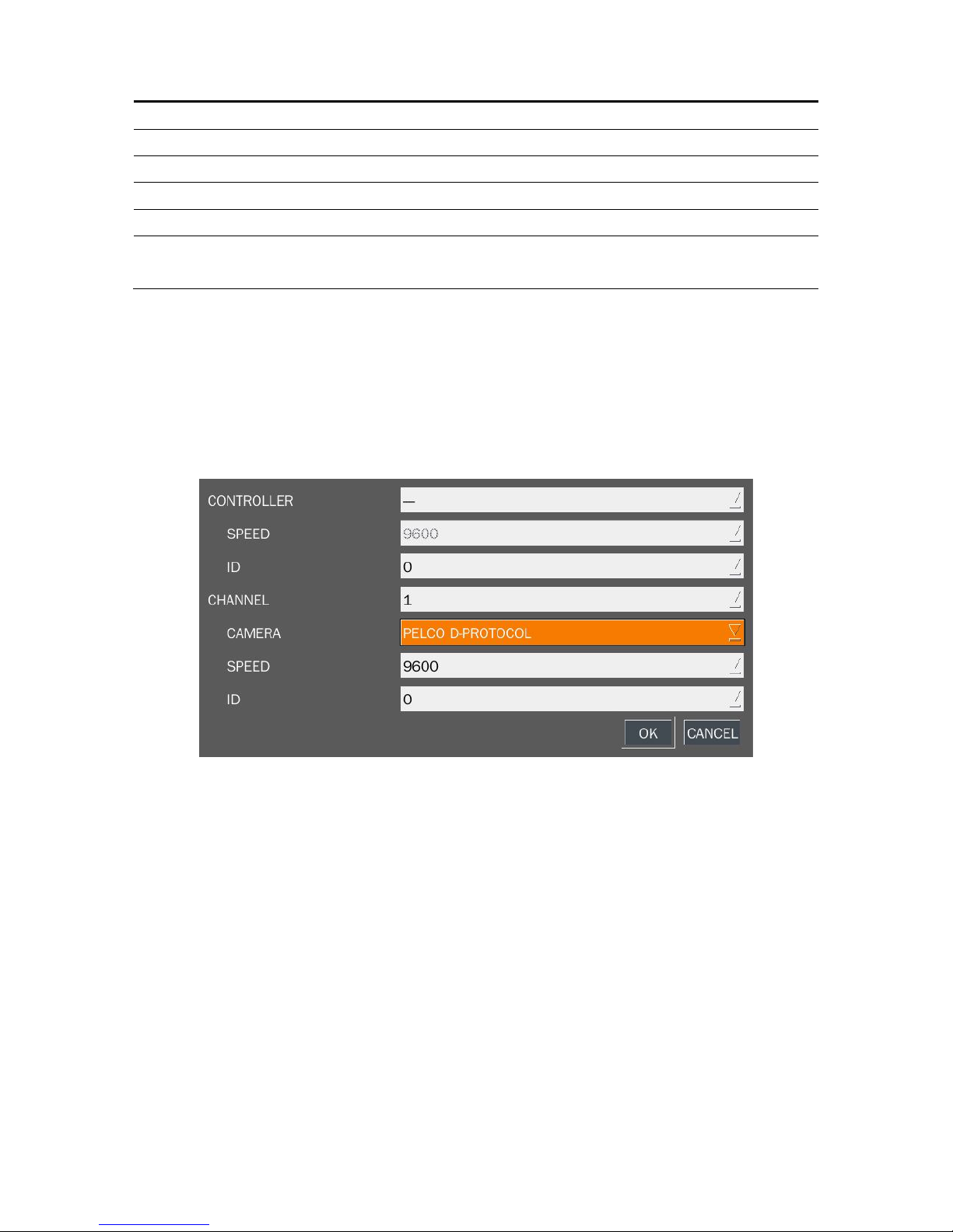
2-4-2 Controller & PTZ Setup
To control the controller and PTZ functions of the camera, connect a controller to the RS-485 port.
① Connect the RS-485 cables of Controller and PTZ camera to the RS-485 port on the rear panel.
② Press SEL button or double click to enter the menu. Then Controller and PTZ menu screen is
displayed.
Figure 2.4.3. Controller and PTZ Control Setup Screen
Note: For speed dome cameras that support RS-485, connect them directly to the RS-485 port. If the
camera is controlled with RS-232C, use an RS-485 to RS-232C signal converter.
On the Controller and PTZ control setup screen, you can select or set the protocol type of the camera that
is the same as the one installed on the site. If the camera has a specific camera ID, select the camera ID
using the control button (◀ ▲ ▶ ▼).
The following options are available on the Controller and PTZ setup screen.
CHANNEL (channel number that the Controller and PTZ is connected to)
NAME (protocol type)
SPEED (19200, 14400, 9600, 4800, 2400)
ID (0-63)

30
2-4-3. Motion Zone Setup
Select MOTION ZONE using the control button (◀ ▲ ▶ ▼) and select either PARTIAL ZONE or FULL
ZONE using the control button (◀ ▲ ▶ ▼). And press the SEL button.
If FULL ZONE is selected, the motion setting screen is not displayed. Only set the level of sensitivity for
MOTION SENSITIVITY.
FULL ZONE: The motion sensor is active on the whole screen.
PARTIAL ZONE: The motion sensor is active in the set detection frame.
Select the sensor detection position using the control button (◀ ▲ ▶ ▼) and press the SEL button.
Then the color of the position which is selected will be changed. Press ESC button to return to the DEVICE
setup menu.
Figure 2.4.4. Motion Zone selection screen
2-5. Setup – Storage Mode
Press the SETUP button and enter the password. The setup menu is displayed as picture below. Select
STORAGE icon and press SEL button to enter the setup menu item. Navigate through the menu items
using the control button (◀ ▲ ▶ ▼) and change the value of the menu item using the control button (◀
▲ ▶ ▼). To return to setup menu screen, press the ESC button.
 Loading...