

Eneo HDD-2080MIR Installation And Operation Manual

INSTALLATION AND OPERATION MANUAL
for
HDD-2080MIR

1
Table of contents
1. Safety Instructions and Notes….......................................................................................................
2. General Descriptions............................................................................……………………………...
3
3
3. Supplied Items......................................................................................……………………………...
4. Part names…………………………….…...................................................…………………………...
5. Installation Instructions......................................................................................……………………...
6. Setup Menu ……………............................................................................…………………………...
7. Specifications ………………………………………………..................................................................
8. Dimensional Drawings ……………………………………………............................................................
4
5
6
10
22
23
2
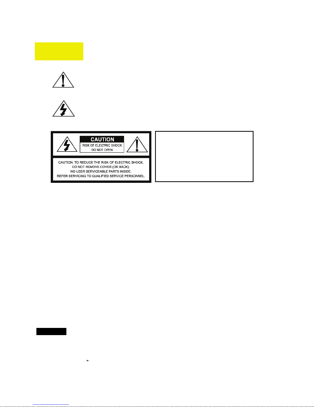
Caution
WARNING
To prevent fire or shock hazard, do not expose the unit to rain or moisture.
The symbol is intended to alert the user to the presence of important
operating and maintenance(servicing) instructions in the literature
accompanying the unit.
The symbol is intended to alert the user to the presence of
uninsulated "dangerous vo l tage " with in the produc t's enc losur e that
may be of sufficient magnitude to constitute a risk of electric shock
to persons.
To prevent electric shocks
and risk of fire hazards, do
NOT use other than specific
power source.
Warning(NTSC version) -- This equipment has been tested and found to comply with the limits for a Class
A digital device, pursuant to part 15 of the FCC Rules. These limits are designed to provide reasonable
protection against harmful interference when the equipment is operated in a commercial environment. This
equipment generates, uses, and can radiate radio frequency energy and, if not installed and used in
accordance with the instruction manual, may cause harmful interference to radio communications.
Operation of this equipment in a residential area is likely to cause harmful interference in which case the
user will be required to correct the interference at his own expense.
Caution -- Any changes or modifications in construction of this device which are not expressly approved by
the party responsible for compliance could void the user's authority to operate the equipment.
Mains power quality should be that of a typical commercial environment. If the user of the model requires
continued operation during power mains interruptions, it is recommended that the model be powered from
an uninterruptible power supply (UPS) or a battery.”
Notice -- The images used in manual are processed to help comprehension and may
differ from actual video of the camera.
WARNING
NEVER USE THIS CAMERA
1. IN AREA WHERE HAS SHOCK OR VIBRATION WHICH RESULTS IN THE
PROBLEM.

3
1. Safety Instructions and Notes
• Please read this safety and operating instructions before putting the camera into operation.
• Keep the manual in a safe place for later reference.
• Pay attention to safety when laying the connection cable and observe that the cable is not subjected to
heavy loads, kinks or damage and no moisture can get in.
• Never open the device such as boards or lens.
The warranty becomes void if repairs are undertaken by unauthorized persons.
• Maintenance and repair have to be carried out only by authorized service centers.
• Use only a mild detergent to clean the housing.
• The camera should never be operated beyond the technical specifications. This can lead to destruction.
• The camera should never be operated in the water.
2. General Descriptions
FULL HD WDR HD-SDI CAMERA, 1920 x 1080/30p(25p)
Highly detailed pictures can be achieved and color reproducibility deserves attention
With ICR mechanism,
- Enhances its sensitivity about 10x at night time
- Can accepts the infrared light
With Intelligent Focus Indicator and FOCUS ADJUST menu,
- Offers easy adjustment of Focus
- Eliminates the mistake of the erratic focus adjustment
With 24VAC/12VDC dual power design,
- Offers the flexibility of installation
- Ensures the reliability
Main features are;
• Full HD, 1920 x 1080/30p(25p)
• True Wide Dynamic Range
• DUAL Filter Switcher – No Focus Shift at Night.
• Day & Night Simulation
• Built-in Mega Pixel Vari-focal Lens (f=2.8~10mm)
• Non Compression digital streaming up to 1.485Gbps
• Intelligent Focus Status Indicator on Screen
• Pointing Zoom which enables the flexible zooming at any area.
• Smart Motion Zoom in combining with Pointing Zoom.
4
• Scale down the image to 720p without loss of field of view
①
④
②
③ ⑤
⑥
⑧
⑦
⑨
• Top performance at low light sensitivity (Sense-up On)
• Improved Noise figure with the enhanced 3D-NR
• D-WDR, BLC/HLC, Digital Zoom(1.1x~8x)
• Motion Detect, Privacy Mask, Anti-Fog, Sense-up(x8)
• LSC(Lens Shade Compensation)
• RS-485(Pelco-D)
• OSD MENU & CVBS Video Sub-out port for easy installation & Maintenance
• Circuit protection against faulty connection.
• Isolated power supply against ground loop problem.
• Hard coated polycarbonate clear Bubble
• Surface / flush mount avail able
• 3-Axis gimbal
• Zoom & Focus Adjustment on gimbal
• IP 68 / IK 10 Protection
• 30 LEDs
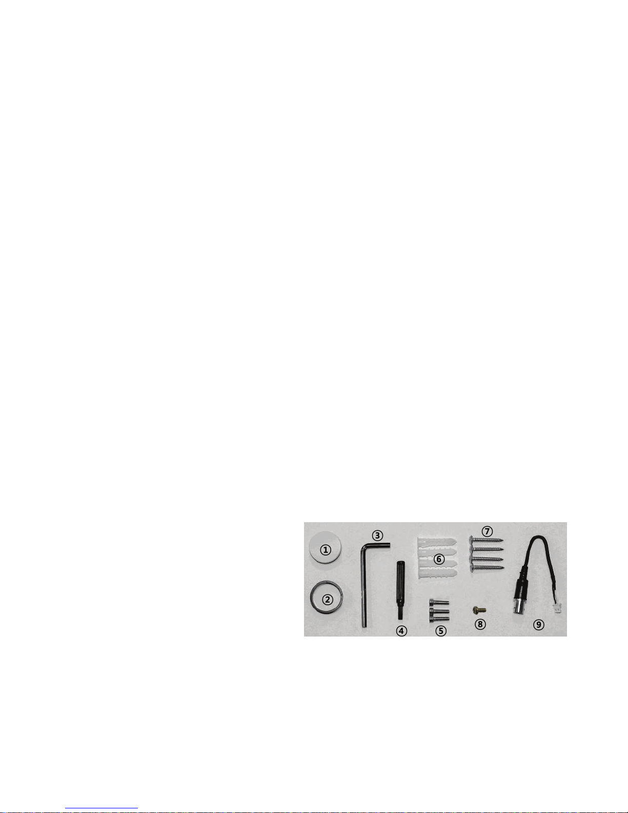
3. Supplied Items
• 1x Vandalproof Dome camera
• 1x Installation and Operating Instructions
• 1x ①Pipe hole cap
• 1x ②Pipe Spacer
• 1x ③L-shape hex wrench
• 1x ④Focus Adjust Driver
• 3x ⑤Wrench Bolt for surface mount
• 4x ⑥Anchors
• 4x ⑦Mount screws
• 1x ⑧BM Screw
• 1x ⑨Sub-out cable

5
4. Control and Part names
ⓐ Zoom & Focus
ⓑ
ⓒ
ⓓ
ⓔ
ⓕ
ⓖ
Video Sub-output
ⓐ
ⓑ
ⓒ
Dome base assembly
Surface Mount Base
Dome Bubble Assembly
ⓘ ⓙ ⓚ
Lens hood
Light sensor for IR LEDs
IR LEDs
Dome base
Mount holes(x3) for dome base
OSD control joy stick
ⓗ
ⓛ
ⓗ
ⓘ Clear bubble
ⓙ Ring cover fixing screws(x3)
ⓚ
Ring cover
ⓛ Pipe hole
ⓜ Dome base fixing screw taps(x3)
ⓝ Surface mount holes(x4)
ⓜ
ⓝ
6
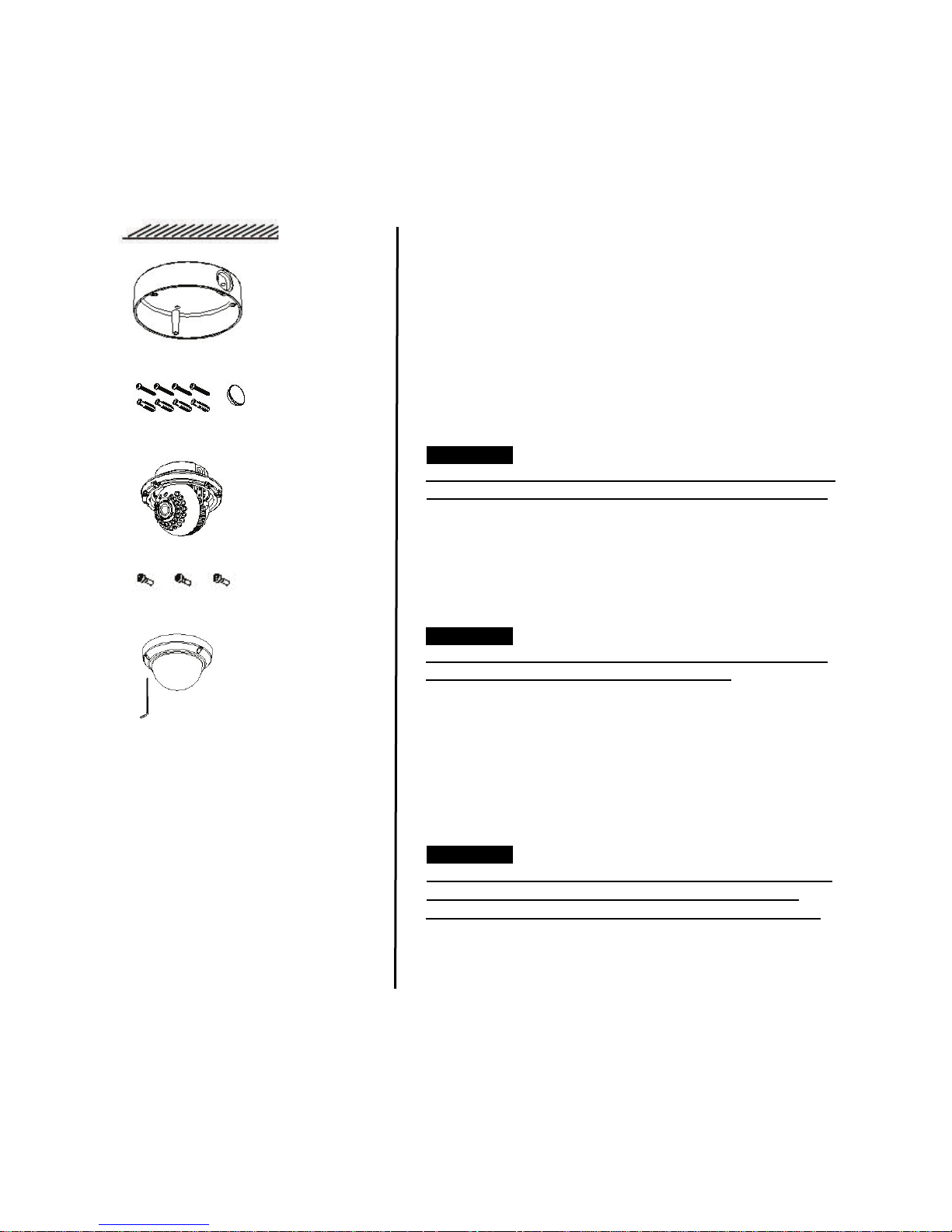
5. Installation
Dome base
assembly
Dome bubble
assembly
L-Wrench
Quick installation guides;
ⓕ
ⓐ
ⓙ
ⓘ
Ceiling or wall
5.1 Surface mount
⑦Mount screws
and ②pipe hole
cap for surface
mount base
⑤Wrench bolts
for fitting to
surface mount
base
1. Locate the mounting template at the installation position
and drill the ceiling or wall if needed.
2. Place Surface mount base on pre-drilled position and fix it
through ⓝSurface mount holes(x4) by using ⑦Mount screws.
Assemble the cable pipe, other wise tighten ①pipe hole cap.
3. Open Dome bubble assembly by loosening ⓙRing cover
fixing screws(x3)
CAUTION
Extreme care should be taken NOT to scratch the dome
surfaces and to protect it from dirt or dust at any time.
Mount holes(x3) for dome base and ⓜ hole should be
4.
aligned before fixing Dome base assembly to Surface mount
base by using ⑤W renc h bolts. And tighte n ⑤wrench bolts
5. Route the power/ video cable to the connecting place.
CAUTION
Care should be taken the cable is NOT to be damaged,
kinked or exposed in the hazardous area.
6. Set the camera’s angle (Pan, Tilt, inclination)
7. Adjust
Zoom & Focus by using ④focus adjust driver.
8 Put Dome bubble assembly over Dome camera assembly and
tighten ⓙRing cover fixing screws(x3) by using ③L-shape hex
wrench
CAUTION
Tighten enough
Ring cover fixing screws(x3) so that
there should be NO gap between ⓑLens hood and
Clear bubble to avoid the light inflow from IR LEDs.
7
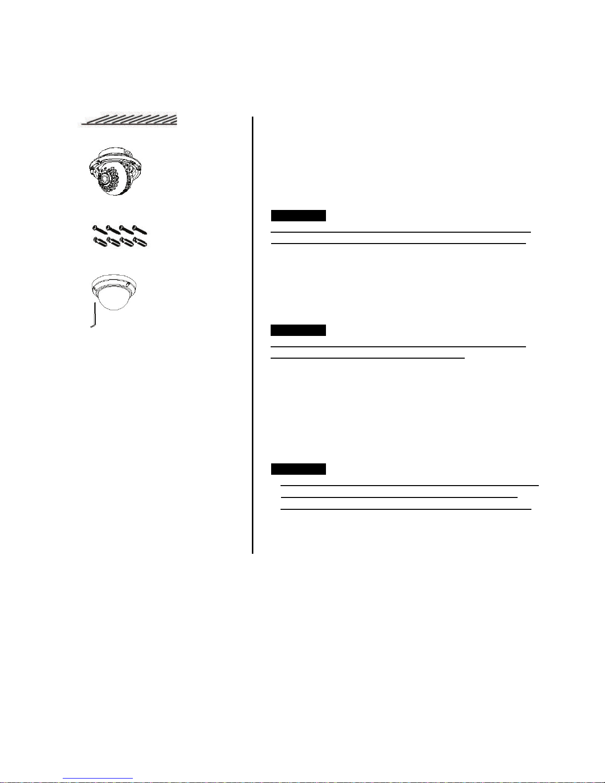
5.2 Flush mount
Dome base
assembly
Dome bubble
assembly
L-Wrench
Quick installation guides;
ⓕ
ⓐ
ⓙ
ⓘ
Ceiling or wall
⑦Mount screws
1. Locate the mounting template at the installation position
and drill the ceiling or wall if needed.
2. Open Dome bubble assembly by loosening ⓙRing cover
fixing screws(x3)
CAUTION
Extreme care should be taken NOT to scratch the dome
surfaces and to protect it from dirt or dust at any time.
3. Place Dome base assembly on pre-drilled position and fix it
through
(Use three screws only out of ⑦Mount screws(4x))
4. Route the power/ video cable to the connecting place.
CAUTION
Care should be taken the cable is NOT to be damaged,
kinked or exposed in the hazardous area.
5. Set the camera’s angle (Pan, Tilt, inclination)
6. Adjust
7. Put Dome bubble assembly over Dome camera assembly and
tighten ⓙRing cover fixing screws(x3) by using ③L-shape hex
wrench
CAUTION
Tighten enough
there should be NO gap between ⓑLens hood and
mount holes(x3) by using ⑦Mount screws.
Zoom & Focus by using ④focus adjust driver.
Ring cover fixing screws(x3) so that
Clear bubble to avoid the light inflow from IR LEDs.
 Loading...