

Eneo HDD-2030PTZ1080 User Manual

User Manual
EN
1/2.8” HDcctv Dome, PTZ,
30x, Day&Night, 4.3~129mm,
1920x1080, Indoor
HDD-2030PTZ1080
CAUTION
RISK OF EL ECTRIC S H OCK
DO NOT OPEN
CAUTI ON: TO RED U CE T HE RISK OF ELECTRI C S H OCK,
WARNING
TO REDUCE THE RISK OF FIRE OR ELECTRIC SHOCK, DO
NOT EXPOSE THIS PRODUCT TO RAIN OR MOISTURE. DO
NOT INSERT ANY METALLIC OBJECTS THROUGH THE
VENTILATION GRILLS OR OTHER OPENINGS ON THE
EQUIPMENT.
CAUTION
DO NOT REMOVE COVER (OR BA CK)
NO USER-SERVICEABLE PARTS INSIDE.
REFER SERVICING TO QUALIFIED SERVICE PERSONNEL.
EXPLANATION OF GRAPHICAL SYMBOLS
The lightning flash with arrowhead symbol, within an
equilateral triangle, is intended to alert the user to the
presence of uninsulated “dangerous voltage” within
the product’s enclosure that may be of sufficient
magnitude to constitute a risk of electric shock to
persons.
The exclamation point within an equilateral triangle is
intended to alert the user to the presence of
important operating and maintenance (servicing)
instructions in the literature accompanying the
appliance.
II

FCC COMPLIANCE STATEMENT
and found to
against harmful interference when the equipment is operated in a
s equipment generates, uses, and can
with the instruction manual, may cause harmful interference to radio
Cet appareil numérique de la classe A est conforme à la norme
This device complies with Part 15 of the FCC Rules. Operation is subject
to the following two conditions: (1) this device may not cause harmful
interference, and (2) this device must accept any interference received,
including interference that may cause undesired operation.
FCC INFORMATION: This equipment has been tested
comply with the limits for a Class A digital device, pursuant to Part 15 of
the FCC Rules. These limits are designed to provide reasonable protection
commercial environment. Thi
radiate radio frequency energy and, if not installed and used in accordance
communications. Operation of this equipment in a residential area is likely
to cause harmful interference in which case the user will be required to
correct the interference at his own expense.
CAUTION: Changes or modifications not expressly approved by the party
responsible for compliance could void the user’s authority to operate the
equipment.
This Class A digital apparatus complies with Canadian ICES-003.
NMB-003 du Canada.
CE COMPLIANCE STATEMENT
WARNING
This is a Class A product. In a domestic environment this product may
cause radio interference in which case the user may be required to take
adequate measures.
III

IMPORTANT SAFETY INSTRUCTIONS
1. Read these instructions.
2. Keep these instructions.
3. Heed all warnings.
4. Follow all instructions.
5. Do not use this apparatus near water.
6. Clean only with dry cloth.
7. Do not block any ventilation openings. Install in accordance with the
manufacturer’s instructions.
8. Do not install near any heat sources such as r adiators, heat r egisters, sto ves,
or other apparatus (including amplifiers) that produce heat.
9. Do not defeat the sa fety purpose of the polarized or grou nding-type plug. A
polarized plug has two blades with one wider than the other. A grounding
type plug has two blades and a th ird grounding pr ong. The wide blade o r the
third prong is provided for your safety. If the provided plug does not fit into
your outlet, consult an electrician for replacement of the obsolete outlet.
10. Protect the power cord from being walked on or pinch ed particularly at plugs,
convenience receptacles, and the point where they exit from the apparatus.
11. Only use attachments/accessories specified by the manufacturer.
12. Use only with the cart, stand, tripod, bracket, or table
specified by the manufacturer, or sold with the apparatus.
When a cart is used, use caution when moving the
cart/apparatus combination to avoid injury from tip-over.
13. Unplug this apparatus during lightning storms or when
unused for long periods of time.
14. Refer all servicing to qualified service personnel. Servicing is r equired when
the apparatus has been damaged in any way, such as power -supply cord or
plug is damaged, liquid has been spilled or objects have fallen into the
apparatus, the apparatus has been exposed to rain or moisture, does not
operate normally, or has been dropped.
15. CAUTION – THESE SERVICING INSTRUCTIONS ARE FOR USE BY
QUALIFIED SERVICE PERSONNEL ONLY. TO REDUCE THE RISK OF
ELECTRIC SHOCK DO NOT PERFORM ANY SERVICING OTHER THAN
THAT CONTAINED IN THE OPERATING INSTRUCTIONS UNLESS YOU
ARE QUALIFIED TO DO SO.
16. Use satisfy clause 2.5 of IEC60950-1/UL60950-1 or Certified/Listed
Class 2 power source only.
IV

Table of Contents
Chapter 1 — Introduction .................................................................................................. 1
1.1 Features ............................................................................................................................... 1
Chapter 2 — Installation and Configuration .................................................................... 3
2.1 Package Contents ............................................................................................................... 3
2.2 Basic Configuration of Dome Camera System .................................................................. 4
2.3 Setting Dome Camera (Dip Switch) .................................................................................... 5
2.4 Setting Dome Camera Address (ID) ................................................................................... 7
2.5 Connections ......................................................................................................................... 7
2.6 Getting Started ..................................................................................................................... 8
Chapter 3 — Program and Operation ............................................................................... 9
3.1 Dome Camera Selection ...................................................................................................... 9
3.2 Accessing the On-Screen Menu Utility .............................................................................. 9
3.3 How to control the On-Screen Menu Utility ....................................................................... 9
3.4 Auto Scan (Shortcut: SCAN) ............................................................................................ 10
3.5 Preset (Shortcut: PRST) ................................................................................................... 12
3.6 Shortcut of Preset Program .............................................................................................. 13
3.7 Tour (Shortcut: TOUR) ...................................................................................................... 14
3.8 Pattern (Shortcut: PTRN) .................................................................................................. 16
3.9 Privacy Zone ...................................................................................................................... 17
3.10 Camera Menu ................................................................................................................... 18
3.11 Dome Communication ..................................................................................................... 21
3.12 Alarm ................................................................................................................................ 22
3.13 Dome Setup ..................................................................................................................... 23
Appendix A — Specifications ......................................................................................... 30
Appendix B — Troubleshooting ..................................................................................... 32
Appendix C — Fastrax Protocol ..................................................................................... 33
V

Chapter 1 — Introduction
1.1 Features
The dome camera and the keyboard controller make up the building blocks for any
surveillance/security system. Using multiple keyboard controllers and multiple dome cameras, no
place is too large for monitoring. Extensible and flexible architecture facilitates remote control
functions for a variety of external switching devices such as multiplexers and DVRs.
• Built-in optical power zoom camera with True Night Shot function
• 240 Preset positions with the individual camera AE setup
• 8 Tours consist of Presets, Patterns, Auto Scans and other Tours can be programmed with over
300 functions and preset locations. While moving, each Preset scan can be watched in smooth
Vector Scan mode.
• 16 Auto Scans with the normal, the vector, and the random mode and the endless Auto-Pan with
13 speed steps
• 8 Patterns (up to 500 second) and 24 Privacy Zones
• 4 Alarm inputs, 2 Alarm outputs (5VTTL)
• Variable speed from 0.1°/sec to 380°/sec
Three Variable speed (SLOW, NORMAL, TURBO)
Turbo speed is 380°/sec with Ctrl key pressed.
• Pan/Tilt speed is inversely proportional to the zoom ratio with the option.
• Maximum speed is 380°/sec when Preset command.
• Auto Calibration from 0.1° to 6° (Tilt range is -10° to 190°)
• Programmable user preferences (alarm, preset, title, etc.)
• 180° Digital Flip
• Up to 3999 selectable camera addresses
• Function Run menu using DVR without function key (Pattern, Scan …)
• Built-in RS-485 receiver driver
• 12VDC or 24VAC for Dome
• Use satisfy clause 2.5 of IEC60950-1/UL60950-1 or Certified/Listed Class 2 power source only.
• Optional Clear bubble with black liner (shelter) for concealing the camera
• Optional Tinted Bubble, Indoor & Outdoor pendant housing with heater & blower, Indoor Flush
mount, Parapet mount & Roof Top mount.
1
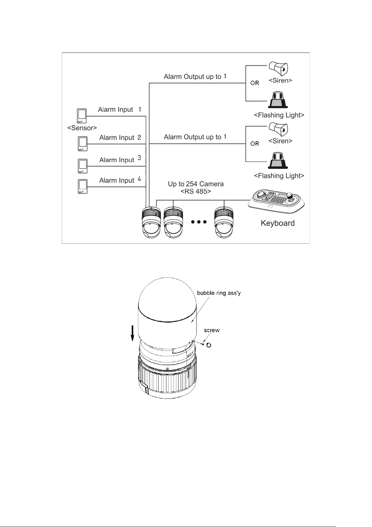
Figure 1 – Typical System Configuration
Figure 2 –Assemble bubble ring ass’y (Optional)
Note: It is recommended to remove camera window for improving picture quality when you use
bubble ring ass’y.
2
Chapter 2 — Installation and Configuration
2.1 Package Contents
The package contains the following.
Dome Camera ………………………1
Bubble Ring ………………………1(Optional)
Instruction Manual (This Document) ………………………1
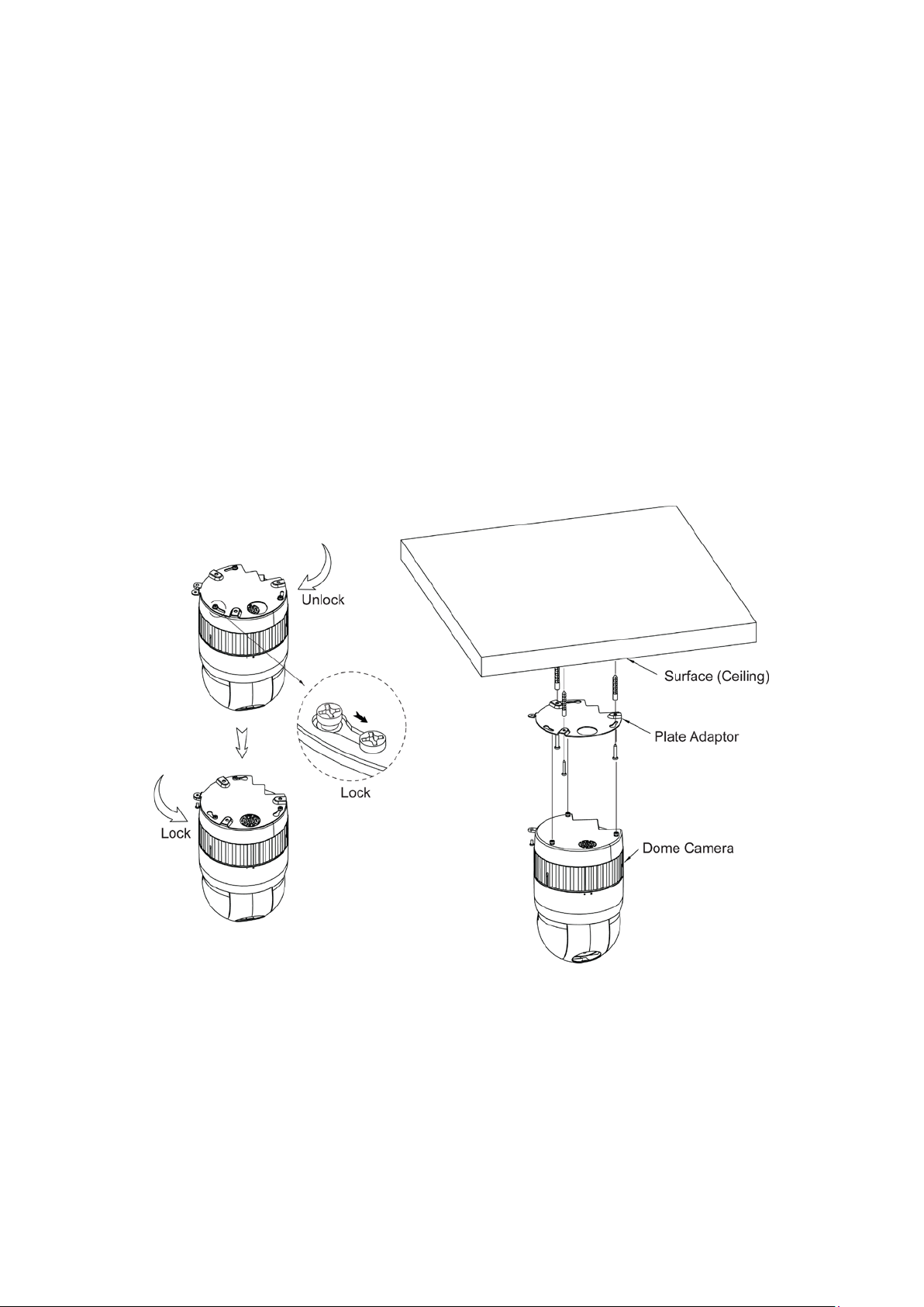
Plate Adaptor ………………………1
16 Pin Cable ………………………1
The dome camera is for use in surface mounting applications and the mounting surface should be
capable of supporting loads up to 4.5kg.
The dome camera’s base should be attached to a structural object, such as hard wood, wall stud
or ceiling rafter that supports the weight of the dome camera.
Figure 3 – Installation
3

2.2 Basic Configurati on of Dome Came ra System
Figure 4 – Basic installation diagram
The dome camera must be installed by qualified service personnel in accordance with all local and
federal electrical and building codes.
The system should be installed according to Figures 4 through 8.
4
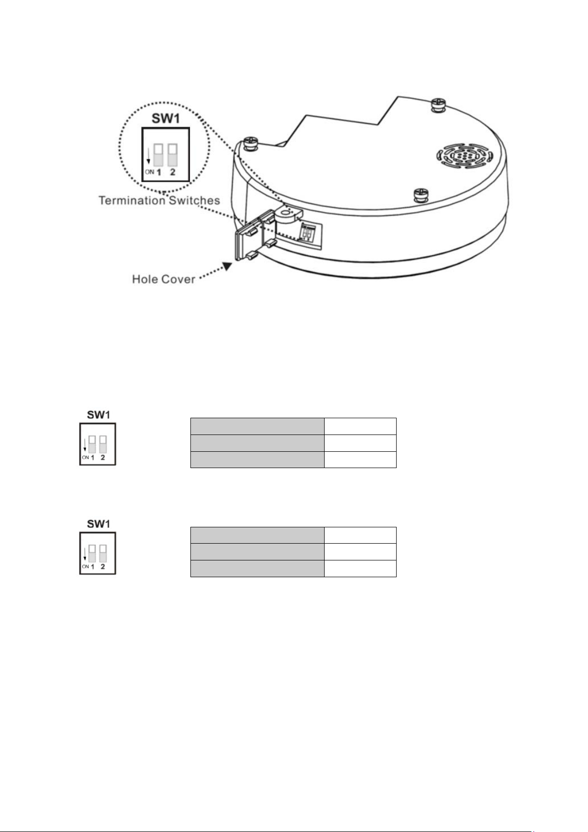
SW1
1
PAL
ON
NTSC
2
Terminated
ON
Not Terminated
OFF
Figure 5 – Layout of Switches
2.3 Setting Dome Camera (Dip Switch)
Figure 6 – Composite Video Signal
Figure 7 – Setting Dome Camera Termination
SW1
OFF
5
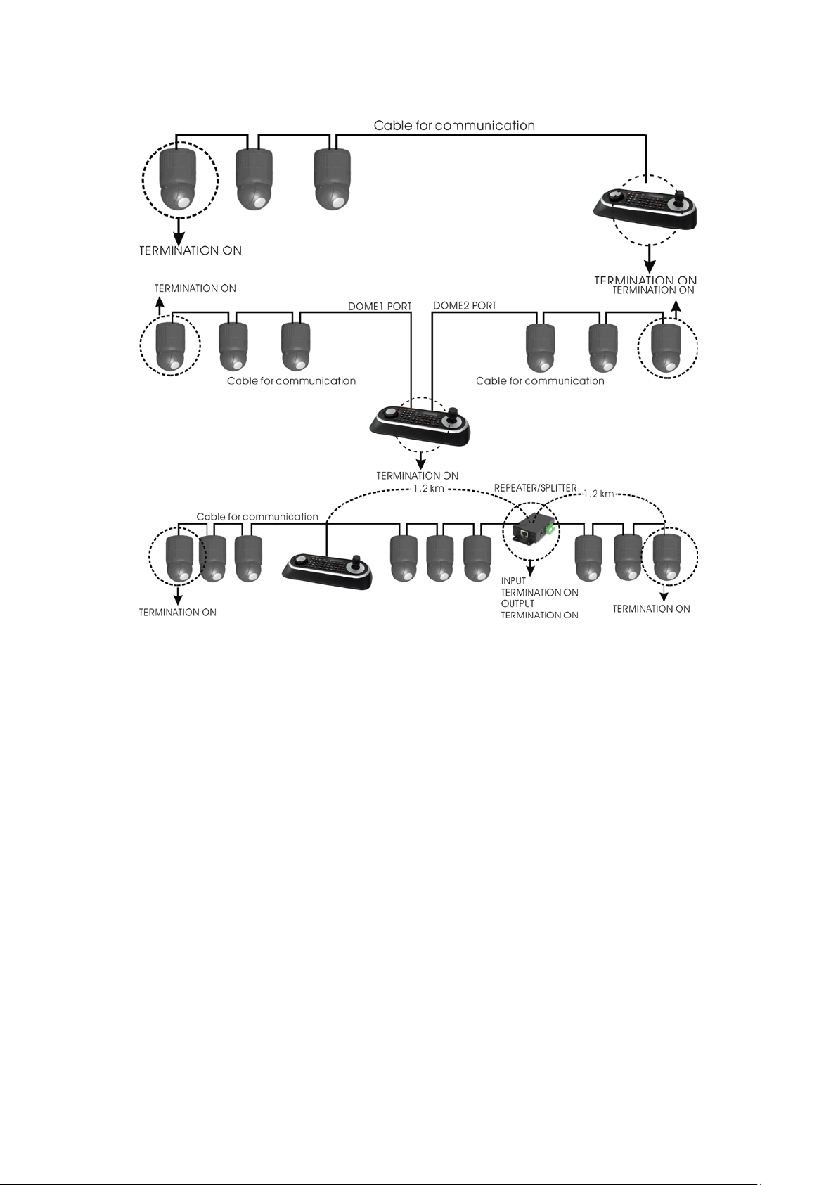
Figure 8 - Termination Diagram
6

2.4 Setting Dome Camera Address (ID)
To prevent damage, each dome camera must have a unique address (ID).
The factory default setting is 1.
Refer to ‘3.11 Dome Communication’ section for detailed information.
2.5 Connections
• Connecting to the RS-485
The dome camera can be controlled remotely by an external device or control system, such as a
control keyboard, using RS-485 half-duplex serial communications signals.
• Connecting HD-SDI Output connector
Connect the HD-SDI output (BNC) connector to the monitor or video input.
• Connecting Alarms
- A1,A2,A3,A4 (Alarm Input 1,2,3,4)
You can use external devices to signal the dome camera to react on events. Mechanical or
electrical switches can be wired to the A1,A2,A3,A4 (Alarm Input 1,2,3,4) and G (Ground)
connectors.
See Chapter 3 — Program and Operation for configuring alarm input.
- G (Ground)
NOTE: All the connectors marked G or GND are common.
Connect the ground side of the alarm input and/or alarm output to the G (Ground) connector.
- AO1,AO2 (5VTTL Alarm Output 1,2)
The dome camera can activate external devices such as buzzers or lights. Connect the device
to the AO1,AO2 (Alarm Output 1,2) and G (Ground) connectors.
See Chapter 3 — Program and Operation for configuring alarm output.
• Connecting the Power
Connect power of 12VDC or 24VAC for the dome camera.
When using a 12VDC adapter, connect the positive (+) pole to the ‘+’ position and
the negative (-) pole to the ‘-’ position.
Use satisfy clause 2.5 of IEC60950-1/UL60950-1 or Certified/Listed Class 2 power source only.
7
 Loading...