

Eneo HDB-2280Z10IR D User Manual [en, de, fr]

Quick Installation Guide
1/3” HDcctv Camera, WDR,
Day&Night, 1920x1080, 5.151mm, 10x AF Zoom, Infra-
DE
EN
FR
red, 12/24V
HDB-2280Z10IR D

Table of content
Notes on safety .............................................................................................................3
Parts supplied ...............................................................................................................3
Part names .....................................................................................................................4
Installation instructions ...............................................................................................5
Pan & Tilt adjustments ..................................................................................................................................................... 6
Power supply connections .............................................................................................................................................7
Operating instructions .................................................................................................9
Using OSD controller........................................................................................................................................................9
Description of the joystick operation ..........................................................................................................9
Description of the ZOOM&FOCUS adjustment .......................................................................................9
Set the video format according to system, EX-SDI or HD-SDI ........................................................................ 10
OSD menu startup ......................................................................................................................................................... 10
OSD menu table.............................................................................................................................................................. 11
Further information ....................................................................................................13
2
Notes on safety
Please also pay attention to the enclosed safety instructions, and carefully read through
this instruction guide before initial operation.
Important points of warning are marked with a caution symbol.
EN
i
Important points of advice are marked with a notice symbol.
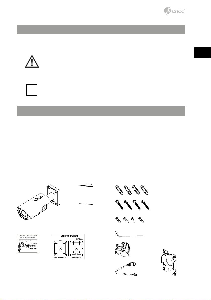
Parts supplied
• Plastic Anchor: 6 x 30mm (4pcs)
• Mounting Screw: 4 x 30mm (4pcs)
• Camera
• Cable Signal Sticker
• Operating Instruction
• Mounting Template
• Assembly Screw: 4 x 14mm (4pcs)
• Torque Wrench: 3mm (1pc)
• Wiring Connector: (1pc)
• Video Sub-out Cable (1pc)
• Easy Bracket
3
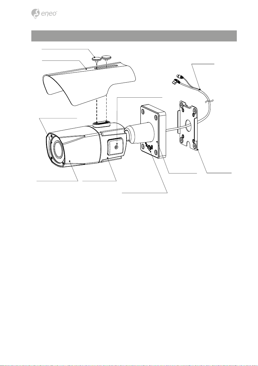
Part names
Sunshield bolt
Sunshield
Dual window
Front case Rear case
Power cable
OSD setup control cover
Bracket Easy bracket
Lock/unlock screw
4
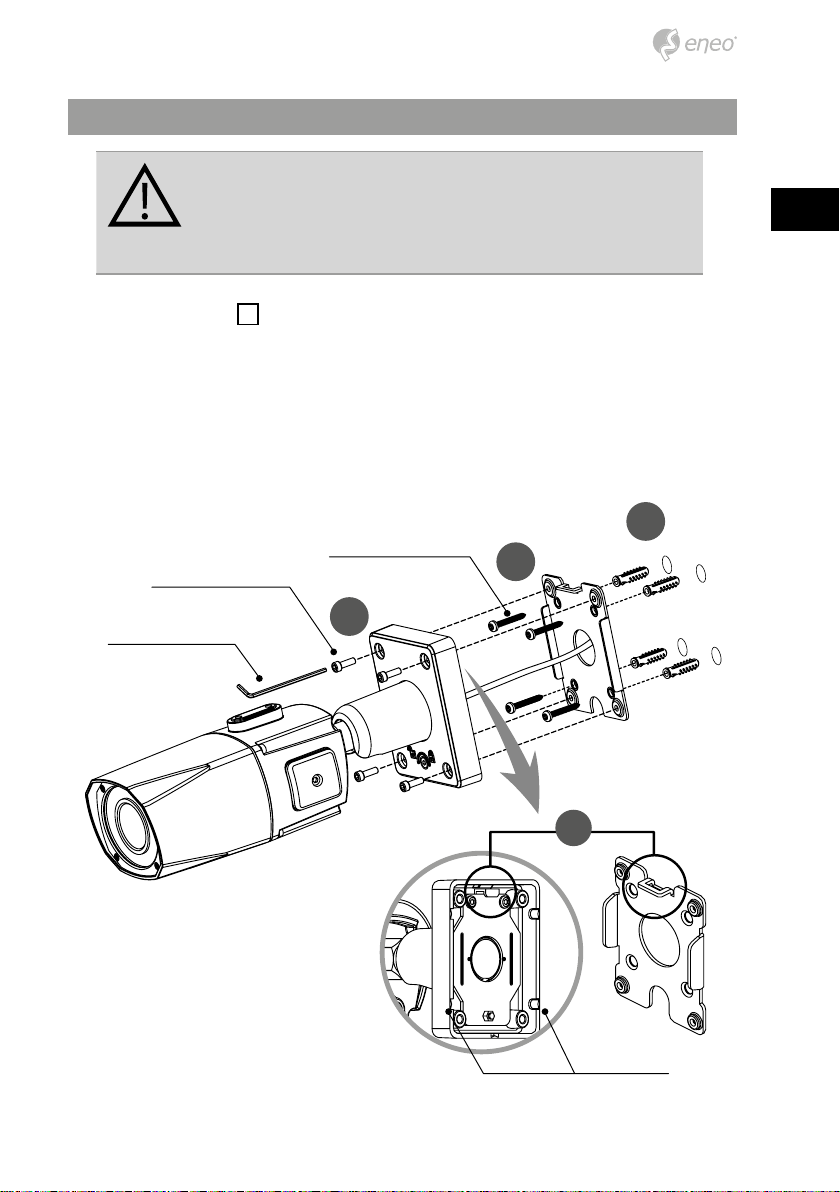
Installation instructions
CAUTION: The camera’s base should be attached to a structural
object, such as concrete, hard wood, wall stud or ceiling rafter
that supports the weight of the camera. If necessary use appropriate mounting material (e.g. anchors) instead of the material
enclosed with the camera.
1. Locate the mounting template at the installation position and drill the ceiling or
wall if needed.
2. Place the easy bracket on pre-drilled position and x it through using mounting
screws(4x30mm). Skip this step when an easy bracket is not installed.
3. Route the power cable to the connecting place. Hook up the camera bracket with
the easy bracket as illustrated below.
4. Fix the camera bracket through using assembly screws (4x14mm).
5. Set the camera’s viewing angle.
6. Put the sunshield to the camera unit and tighten the sunshield-bolts.
The easy bracket can not be installed on the ceiling.
i
EN
Assembly Screw: 4x14mm
Torque Wrench
Mounting Screw 1: 4x30mm
4
1
2
3
Cable exit
5
CAUTION:
°9
Extreme care should be taken NOT to scratch the window in front
of lens.
Care should be taken the cable is NOT to be damaged, kinked or
exposed in the hazardous area.
Do not expose the camera directly to a strong light source such
as the sun or spot light.
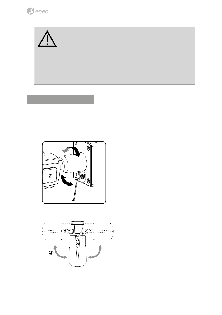
Pan & Tilt adjustments
• Unlock the screw on the camera bracket through using the torque wrench supplied
• Set the camera’s viewing angle then lock the screw on the bracket.
Adjustment of viewing angle with a bracket
Lock/Unlock Screw
Torque wrench
1. Pan limit: Pan is limited to +/- 90°.
90
6
0°
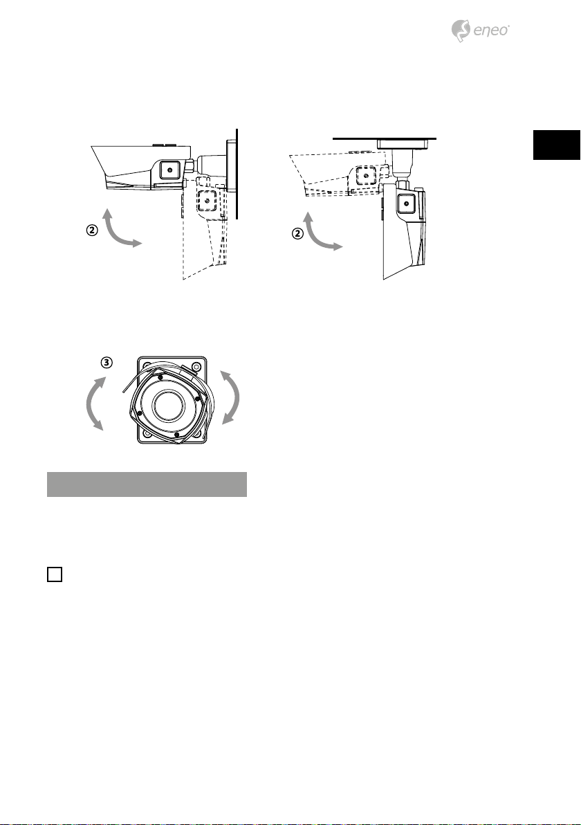
2. Tilt limit: Tilt is limited to 0°(2°) min ~ 90° max. for wall(ceiling) installation respectively with reference to the wall(ceiling) when the inclination of camera module is
0°, that is, the image is aligned horizontally.
EN
90°
on the wall on the ceiling
3. Inclination limit (Horizontal image alignment): Inclination limited to +/-90° max.
±90°
88°
Power supply connections
Make sure the power is removed before the installation. Camera can work with either
24AC or 12VDC, dual voltage power. Primary and secondary grounds are completely
isolated to avoid the possible ground-loop problems.
i
In case that HD-SDI/EX-SDI Inputs are not supported in monitor, please use HD-SDI/
EX-SDI Converter to connect HD-SDI/EX-SDI cable with monitor. Some computer monitors or TVs may not support 30p/25p. In this case, HD-SDI/EX-SDI DVR which can convert
the frame rate to 60p/50p is highly recommended. Please check specication of monitor
before installation.
7
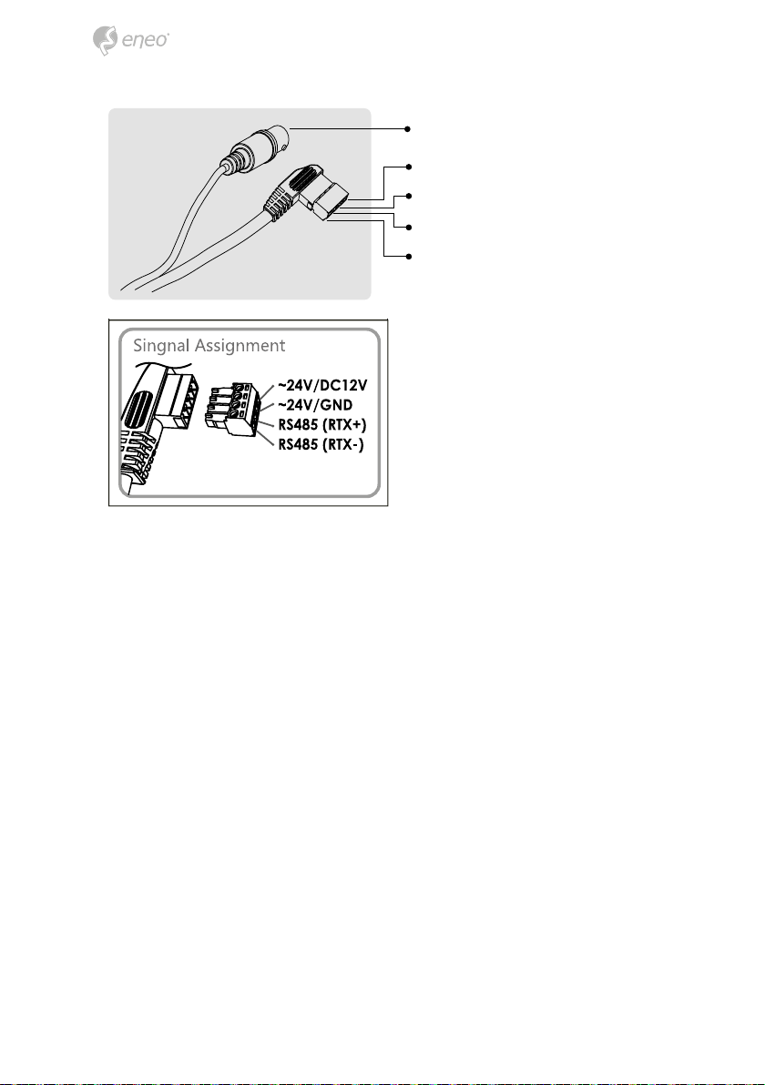
VIDEO (BNC)
AC24V/DC12V (Red wire)
AC24V/GND (Black wire)
RTX+/RS485 (White wire)
RTX-/RS485 (Gray wire)
Attach the Signal Assignment Sticker in a visible spot for wiring reference.
8
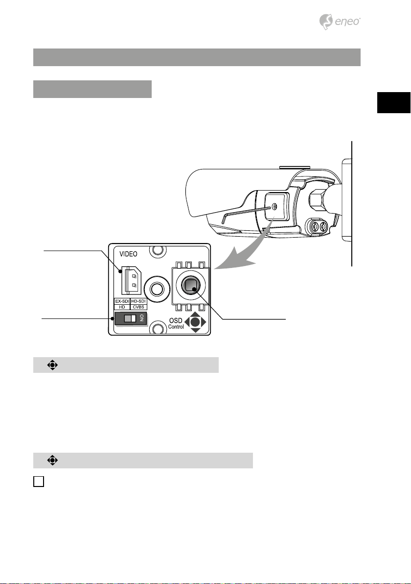
Operating instructions
SUB-OUT
Using OSD controller
Setup menu can be accessed and controlled by OSD control joy stick on the side of camera unit. Five commands are available with the joy stick.
Video Sub-out Connector
Cover Open
Video format Switch OSD Control Joy Stick
EN
Description of the joystick operation
1. SET Key (●) : Access to the menu or enter the setting.
2. UP/DOWN Key (▲/▼) : Choose the desired sub-menu and to move the cursor up or
down.
3. LEFT/RIGHT Key (◄/►) : Set up the value of the selected menu. Used to adjust the
desired menu selection and to move the cursor left or right.
Description of the ZOOM&FOCUS adjustment
Works only when OSD Menu is inactive.
i
1. ▲ : Zoom In
2. ▼ : Zoom Out
3. ◄ : Focus Near
9
4. ► : Focus Far
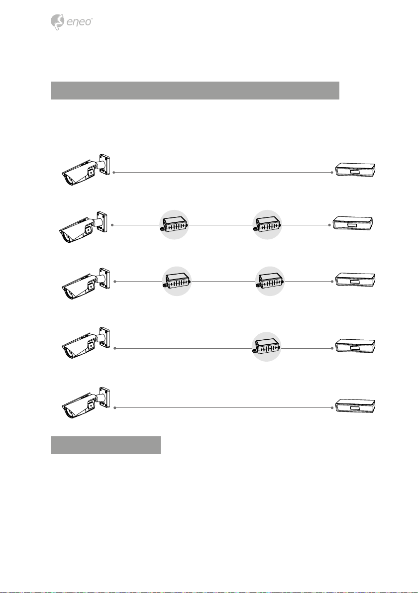
Set the video format according to system, EX-SDI or HD-SDI
To select the camera’s output video format (EX-SDI or HD-SDI), use the Video format
Switch on the side of the camera. Only one format can be used at a time (see also “Using
OSD controller”).
1M~120M via RG59u or 5C2V cable
Camera (HD-SDI)
1M~120M via
RG59u or 5C2V
cable
Camera (HD-SDI)
1M~120M via
RG59u or 5C2V
cable
Camera (HD-SDI)
Camera (EX-SDI)
Camera (EX-SDI) DVR (EX-SDI)
HDA-3000E
(HD-SDI)
HDA-3000E
(EX-SDI)
350M+ via RG59u or 5C2V cable
1M~120M via RG59u or
5C2V cable
HDA-3000E
(HD-SDI)
350M+ via RG59u or
5C2V cable
HDA-3000E
(EX-SDI)
HDA-3000E
(EX-SDI)
350M+ via RG59u or 5C2V cable
1M~120M via
RG59u or 5C2V
cable
1M~120M via
RG59u or 5C2V
cable
1M~120M via
RG59u or 5C2V
cable
DVR (HD-SDI)
DVR (HD-SDI)
DVR (HD-SDI)
DVR (HD-SDI)
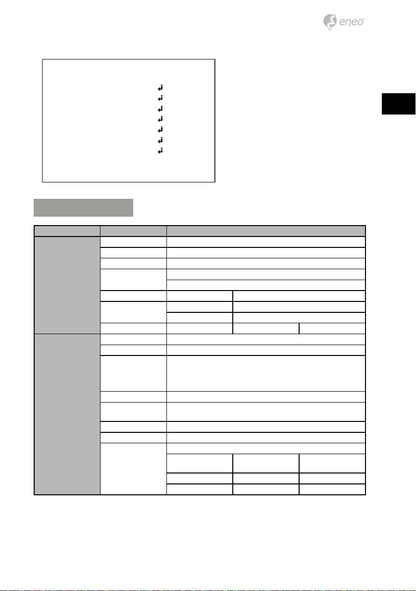
OSD menu startup
Press ‘●’ (OSD menu Joy stick key) down to access the setup menu mode.
• EXIT : Exits the setup menu without save.
• SAVE : Saves the menu settings.
• DFLT : Reset to the factory defaults.
• BACK : Go back to the previous menu.
10
/'07
<11/(1%75
':21574'
9*+6'$#.
+/#)'
+06'..+)'0%'
52'%+#.(70%
&+52.#;
=':+6? =5#8'? =&(.6?
OSD menu table
MAIN MENU SUB MENU CONFIGURATION
FOCUS AUTO, ONE PUSH, MANUAL
DISTANCE 0.1m, 1.0m, 3.0m, 5.0m, 10.0m
ZOOM SPEED 0~7
ONE PUSH
1DAY~10DAYS
PRESET 1~4
MODE OFF, ON
30/25fps]
x4, x2, 1/30(25), 1/60(50), 1/120(100), 1/250~1/30,000sec
60/50fps]
x8, x4, x2, 1/60(50), 1/120(100), 1/250~1/30,000sec
30/25fps] OFF/ x2, x4
60/50fps] OFF/ x2, x4, x8
OFF
WDR LEVEL
BLC POSITION, SIZE 0~20
HLC LEVEL, COLOR 0~13
ZOOM/FOCUS
EXPOSURE
LENS REFRESH
E.ZOOM OFF/ON max. x2~x19, x21, x23, x25, x28, x32
ZOOM PRESET
HOME POSITION OFF/ON DWELL TIME 3sec~60sec
MODE AUTO/ IRIS.P/ SHUT.P/ MANUAL
AGC OFF/ON (0~10)
SHUT SPEED
IRIS 0~20
DSS
FLICKERLESS OFF/ON
BRIGHTNESS 0~20
BACK LIGHT
EN
MID-HIGH, HIGH, LOW,
MID-LOW,MIDDLE
11
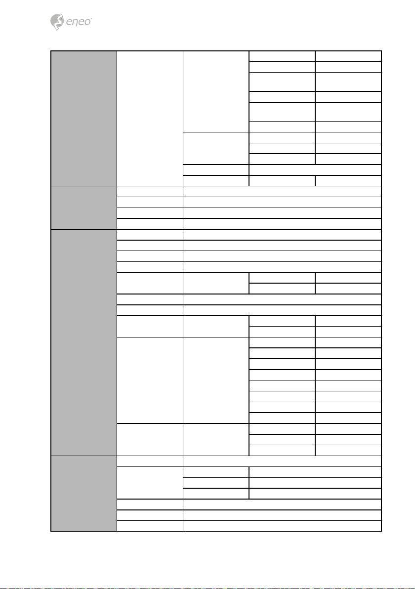
EXPOSURE DAY&NIGHT
MODE AUTO, ONE PUSH, MANUAL, INDOOR, OUTDOOR
WHITE BAL
IMAGE
SPECIAL FUNC
RED GAIN 0~20 (control only in MANUAL mode)
BLUE GAIN 0~20 (control only in MANUAL mode)
CHROMA 0~20
DNR OFF, LOW, MIDDLE, HIGH, AUTO
MIRROR OFF, H, V, H&V
SHARPNESS 0~10
ACE OFF, LOW, MIDDLE, HIGH
DEFOG OFF/ON
FREEZE OFF, ON
GAMMA 0.45/ 0.55/ 0.65/ 0.75
PRIVACY OFF/ON
MOTION OFF/ON
DIS OFF/ON
DEFECT
IMAGE RANGE
SYSTEM NTSC(30/60fps) or PAL(25/50fps)
HD FORMAT 1080p /30(25)fps, 1080p /60(50)fps, 720p/30(25)fps, 720p/60(50)fps
COMM ID, BAUD RATE, PROTOCOL
DELAY 0~255sec
THRS 0~28
AUTO
EXT-IN
DAY
NIGHT BURST OFF, ON
FULL
COMP
USER LEVEL (0~32)
GAP
IR DETECTION OFF, ON
IRDET LEVEL
BURST OFF, ON
DELAY 0~255sec
BURST OFF, ON
POLARITY ACTIVE LOW, ACTIVE HIG
MODE AUTO, MANUAL
LEVEL LOW, MIDDLE, HIGH
COLOR 0~13
TRANS 0~4
AREA# 1~3
MODE OFF, ON
SENSITIVITY 0~20
POSITION
SIZE
INTERVAL 0~255
DWELL TIME 0~255
ZOOM PRESET OFF, ON
RANGE 10%, 20%, 30%
FILTER LOW, MIDDLE, HIGH
AUTO C OFF, Half, Full
LOW, MID-LOW, MIDDLE,
MID-HIGH, HIGH
LOW, MID-LOW, MIDDLE,
MID-HIGH, HIGH
12
 Loading...