

Eneo HDB-2180Z03IR Installation And Operation Manual

INSTALLATION AND OPERATION MANUAL
for
HD%-280=,5

1
Table of contents
1. Safety Instructions and Notes….......................................................................................................
2. General Descriptions............................................................................……………………………...
3
3
3. Supplied Items......................................................................................……………………………...
4. Part names…………………………….…...................................................…………………………...
5. Installation Instructions......................................................................................……………………...
6. Setup Menu ……………............................................................................…………………………...
7. Specifications ………………………………………………..................................................................
8. Dimensional Drawings ……………………………………………............................................................
10
23
24
4
5
6
2
Caution
WARNING
To prevent fire or shock hazard, do not expose the unit to rain or moisture.
The symbol is intended to alert the user to the presence of important
operating and maintenance(servicing) instructions in the literature
accompanying the unit.
The symbol is intended to alert the user to the presence of
uninsulated "dangerous voltage" within the product's enclosure that
may be of sufficient magnitude to constitute a risk of electric shock
to persons.
To prevent electric shocks
and risk of fire hazards, do
NOT use other than specific
power source.
Warning(NTSC version) -- This equipment has been tested and found to comply with the limits for a Class
A digital device, pursuant to part 15 of the FCC Rules. These limits are designed to provide reasonable
protection against harmful interference when the equipment is operated in a commercial environment. This
equipment generates, uses, and can radiate radio frequency energy and, if not installed and used in
accordance with the instruction manual, may cause harmful interference to radio communications.
Operation of this equipment in a residential area is likely to cause harmful interference in which case the
user will be required to correct the interference at his own expense.
Caution -- Any changes or modifications in construction of this device which are not expressly approved by
the party responsible for compliance could void the user's authority to operate the equipment.
Mains power quality should be that of a typical commercial environment. If the user of the model requires
continued operation during power mains interruptions, it is recommended that the model be powered from
an uninterruptible power supply (UPS) or a battery.”
Notice -- The images used in manual are processed to help comprehension and may
differ from actual video of the camera.
WARNING
NEVER USE THIS CAMERA
1. IN WATER.
2. IN AREA WHERE HAS SHOCK OR VIBRATION WHICH RESULTS IN THE
PROBLEM FOR AUTO FOCUSING.

3
1. Safety Instructions and Notes
• Please read this safety and operating instructions before putting the camera into
operation.
• Keep the manual in a safe place for later reference.
• Pay attention to safety when laying the connection cable and observe that the cable is not
subjected to
heavy loads, kinks or damage and no moisture can get in.
• Never open the device such as boards or lens.
The warranty becomes void if repairs are undertaken by unauthorized persons.
• Maintenance and repair have to be carried out only by authorized service centers.
• Use only a mild detergent to clean the housing.
• Keep clean the window surface from the dirt or dust, which may reflect the infrared light to
the lens at night..
• The camera should never be operated beyond the technical specifications. This can lead
to destruction.
• The camera should never be operated in the water.
2. General Descriptions
This camera realizes the natural and crisp image as you see the scene in front of you by
adopting Auto Focus Full HD(1920x1080p) camera module.
Highly detailed pictures can be achieved and color reproducibility deserves attention.
With 2.4X Optical Zoom and 32x Digital Zoom,
- Offers the flexible observation
- Provides max. 76x zoom
With ICR mechanism,
- Enhances its sensitivity about 10x at night time
- Can accepts the infrared light
With 24VAC/12VDC dual power design,
- Offers the flexibility of installation
- Ensures the reliability
Main features are;
• HD-SDI output
• Optical 2.4X Auto Focus Zoom • Digital 32X Zoom
• f9~22mm, 2.4X Day & Night Zoom Lens
• 1920x1080p(30fps/25fps)
• Wide Dynamic Range

4
• Sense Up(~x8) / AGC(0~20) / 3D Noise Reduction
• Scale down the image to 720p without loss of field of view
• SMART MOTION ZOOM(Automatic Zoom IN/OUT when motion is detected)
• Pointing Zoom which enables the flexible zooming at any area.
• Motion Detection / Motion Deblur / Privacy Mask / Defog
• Focusing Status Indicator on Screen
-(Blue) Focusing in process
-(White) Focusing Completed
• Pixel Defect Compensation
• ID / TITLE / ZOOM RATIO Display
• H / V / HV FLIP
• Lens Refresh / Lens Initializing Set / LSC(Lens Shade Compensation)
• Enhanced Sensitivity by DSS technology
• Remote Control via RS-485(Pelco-D, Pelco-P)
• OSD Menu & Video Sub-out for Easy installation and Maintenance
• Input voltage: 24VAC/12VDC (Dual Power)
• Circuit protection against faulty connection.
• Isolated power supply against ground loop problem.
• Built in cooling Fan and Heating function
• One touch locking bracket • Easy installation pad
• 4 High power LEDs • IP 68 Protection
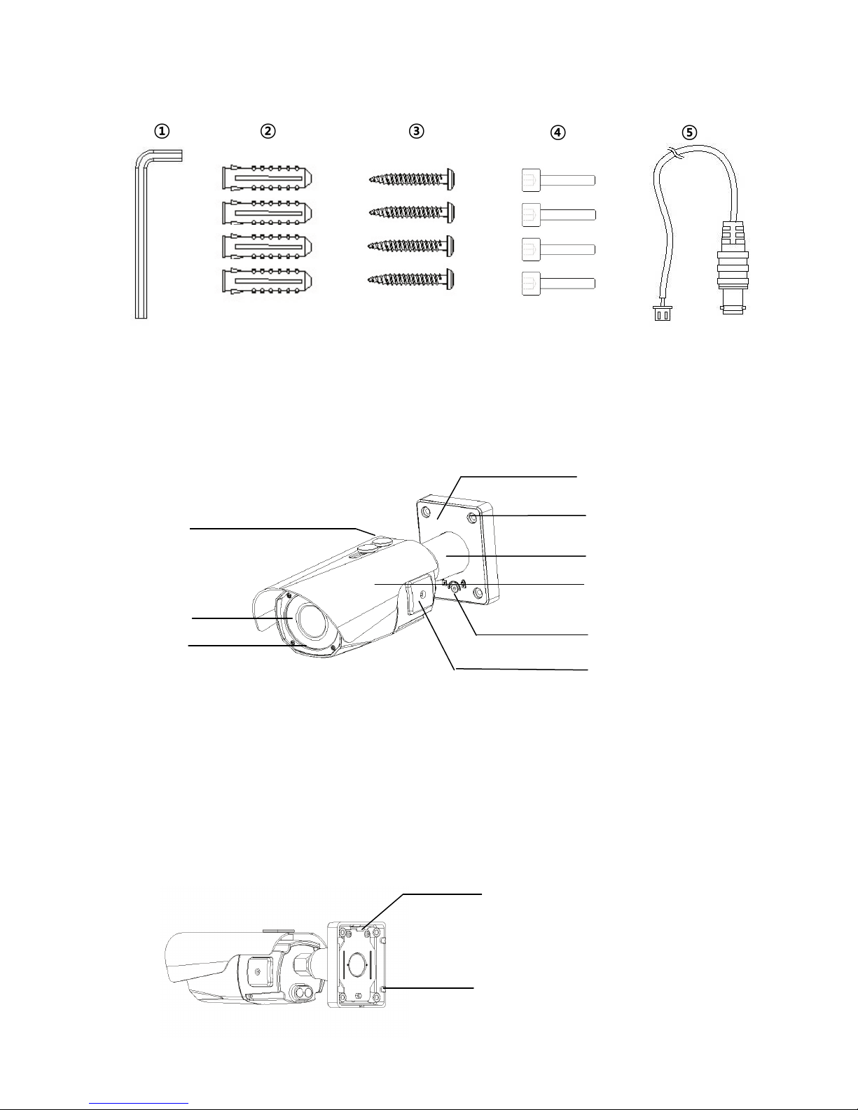
3. Supplied Items
• 1x MegaPixel AF Zoom Camera
• 1x Installation and Operating Instructions
• 1x Mounting template
• 1x Easy Bracket
• 1x ①3mm Hex L-wrench
• 4x ②anchors
• 4x ③Wall fixing screws
• 4x ④M4 Wrench Bolts
• 1x ⑤Video Sub-out cable
5
① ② ③ ④ ⑤
ⓐ Fixing screw for Sunshield(x2)
IR LED
ⓒ
ⓓ Bracket Foot
ⓔ
ⓕ
ⓖ Sunshield panel
ⓗ
ⓘ OSD cover
4. Part Names
4.1 Front view
ⓓ
ⓐ
ⓑ
ⓒ
ⓑ
Window
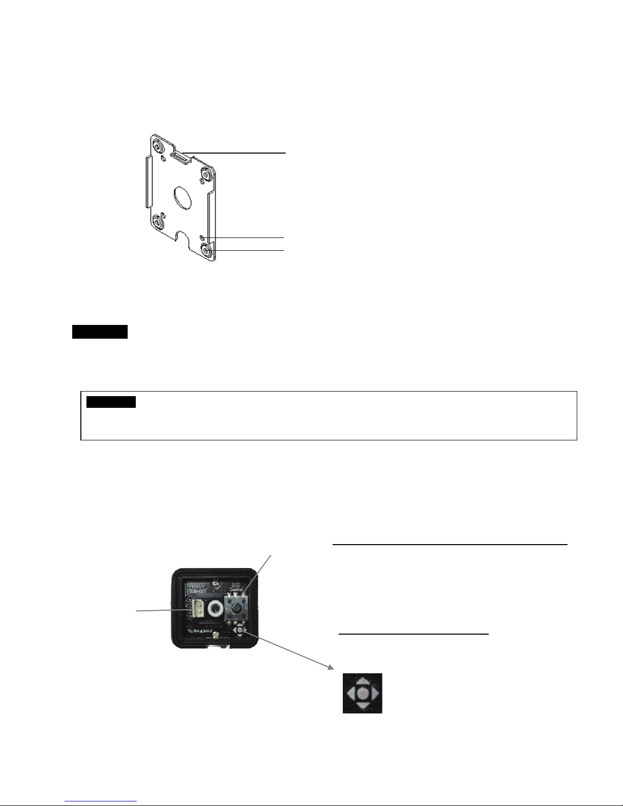
4.2 Rear side view
ⓔ
ⓕ
ⓖ
ⓗ
ⓘ
Foot mount Hole(x4)
Bracket Lock
Arm assembly
ⓙ
ⓙ Hook for Easy Bracket
ⓚ Cable Exits(x5)
ⓚ
6
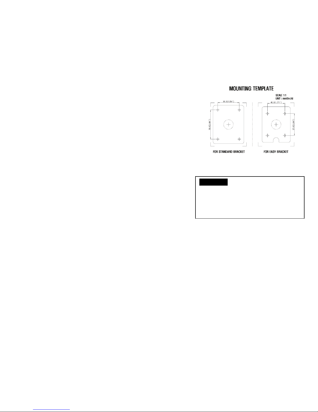
ⓜ
VIDEO
Joy stick
Zoom & Focus Adjustment
(Only works when OSD Menu is not operating)
▲ Zoom In
SYMBOL descriptions for joystick operation;
☟
4.3 Easy Bracket
ⓛ
ⓛ Peg for Easy Bracket Hook(ⓛ)
ⓜ Wall Mount hole(x4)
ⓝ Bracket foot fixing hole(x4)
ⓝ
CAUTION - Easy Bracket can not be installed on the ceiling.
When it is installed on the wall, ⓛPeg for Easy bracket Hook must be placed upwardly.
5. Installation Instructions
WARNING NEVER USE THIS CAMERA
1) in WATER.
2) in area where has SHOCK or VIBRATION which results in the problems for Auto Focus operation.
• Make sure the power is removed before the installation.
• Follow the order for applying power.
First, connect the low voltage (AC24V or DC12V), then plug the AC adapter to AC outlets to avoid an
improper reset from power jitter and a damage from the surge voltage when no load.
SUB-OUT
connector
-▲,▼,◀,▶ denotes the directions of Joystick lever
operation.
-
denotes the long press down straightly
for about 1.5 seconds.
▼ Zoom Out
◀ Focus Near
▶ Focus Far
7
CAUTION - Easy Bracket can not be
be placed upwardly.
5.1 Mounting the camera on wall
5.1.1 Without using an Easy Bracket.
1) Drill the holes on wall or ceiling using a supplied template.
2) Insert the ②anchors to the drilled holes
3) Match ⓔFoot mount Hole(x4) to the drilled position
4) Fix the bracket by using ③Wall fixing screws
5.1.2 With using an Easy Bracket.
1) Drill the holes on wall using a supplied template.
2) Insert the ②anchors to the drilled holes
3) Match the EASY BRACKET to the drilled position
4) Fix the EASY BRACKET by using ③Wall fixing screws
5) Connect hook(ⓙ) to peg(ⓛ)
6) Fix ⓓBracket Foot to EASY BRACKET by using
④wrench bolts through ⓔFoot mount Hole(x4)
installed on the ceiling.
When it is installed on the ceiling,
ⓛPeg for Easy bracket Hook must
 Loading...