

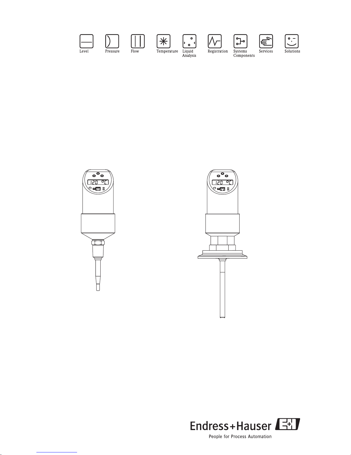
Endress+Hauser Thermophant T TTR35 Operating Manual
Operating manual
Thermophant T TTR31, TTR35
Temperature switch
BA201R/09/en/02.05
51009833
Release 01.01.00

TTR31, TTR35
Table of contents
1 Safety instructions. . . . . . . . . . . 3
1. 1 Designated use . . . . . . . . . . . . . . . . . . . . . . 3
1. 2 Installation, commissioning and operation . . 3
1. 3 Operational safety . . . . . . . . . . . . . . . . . . . . 3
1. 4 Return . . . . . . . . . . . . . . . . . . . . . . . . . . . . 3
2 Device identification . . . . . . . . . 4
2. 1 Nameplate . . . . . . . . . . . . . . . . . . . . . . . . . 4
3 Installation . . . . . . . . . . . . . . . . 5
3. 1 Incoming acceptance, storage . . . . . . . . . . . 5
3. 2 Dimensions . . . . . . . . . . . . . . . . . . . . . . . . 5
3. 3 Process connection . . . . . . . . . . . . . . . . . . . 6
3. 4 Installation instructions . . . . . . . . . . . . . . . 7
4 Wiring . . . . . . . . . . . . . . . . . . . . 8
4. 1 DC voltage version with M12 connector . . . 8
4. 2 DC voltage version with valve connector . . 8
5 Operation . . . . . . . . . . . . . . . . . 9
5. 1 On-site operation . . . . . . . . . . . . . . . . . . . . 9
5. 2 Operation with PC and Readwin® 2000 . 17
9 Dangerous good sheet . . . . . . .27
6 Accessories . . . . . . . . . . . . . . . 18
6. 1 Adapter concept for TTR35 . . . . . . . . . . . 18
6. 2 Welding bosses and coupling . . . . . . . . . 20
6. 3 Electrical connection . . . . . . . . . . . . . . . . 21
6. 4 Configuration kit . . . . . . . . . . . . . . . . . . . 22
7 Trouble-shooting. . . . . . . . . . . 23
7. 1 Errors and warnings . . . . . . . . . . . . . . . . . 23
7. 2 Repair . . . . . . . . . . . . . . . . . . . . . . . . . . . 24
7. 3 Disposal . . . . . . . . . . . . . . . . . . . . . . . . . . 24
7. 4 Change status (release) . . . . . . . . . . . . . . . 24
7. 5 Release history . . . . . . . . . . . . . . . . . . . . 24
8 The most important
technical data . . . . . . . . . . . . . 25
8. 1 Power supply . . . . . . . . . . . . . . . . . . . . . . 25
8. 2 Output . . . . . . . . . . . . . . . . . . . . . . . . . . . 25
8. 3 Operating conditions . . . . . . . . . . . . . . . . 25
2 Endress+Hauser

TTR31, TTR35 Safety instructions
1 Safety instructions
1. 1 Designated use
The Thermophant T is a temperature switch for monitoring, displaying and regulating process
temperatures. The device has been safely built with state-of-the-art technology and meets the
applicable requirements and EC Directives. It can, however, be a source of danger if used incorrectly or for anything other than the designated use.
1. 2 Installation, commissioning and operation
Installation, electrical connection, commissioning, operation and maintenance of the measuring
system must be carried out by trained, qualified specialists authorised to perform such work by
the facility's owner-operator. The specialist must have read and understood these Operating Instructions and must follow the instructions they contain. The device may only be modified and
repair work carried out if this is explicitly permitted in the Operating Instructions. Damaged devices which could be a source of danger may not be commissioned and must be labelled and
identified as defective.
1. 3 Operational safety
• Functional safety
The Thermophant T temperature switches were developed according to the standards IEC
61508 and IEC 61511-1 (FDIS). The device version with PNP switch output and additional
analog output is equipped with fault detection and fault prevention facilities within the
electronics and software. This device version can therefore be used to monitor temperature
up to SIL 2 (Safety Integrity Level). The attainable SIL value is determined by the safety
technical characteristics of probability of failure, hardware fault tolerance and the safe failure
fraction. Details on this may be found in the Functional Safety Manual (in development).
• Ex-area
The Thermophant T is not approved for use in Ex-areas.
1. 4 Return
The following procedures must be carried out before a device is returned to Endress+Hauser:
• Always enclose a fully completed “Declaration of Contamination” form with the device. Only
then can Endress+Hauser transport and examine a returned device. A copy of the “Declaration of Contamination” can be found on the second last page of these Operating Instructions.
• Remove all fluid residues. This is particularly important if the fluid is hazardous to health, e.g.
flammable, toxic, caustic, carcinogenic, etc.
Warning!
#
Do not return a measuring device if you are not absolutely certain that all traces of hazardous
substances have been removed, e.g. substances which have penetrated crevices or diffused
through plastic.
Endress+Hauser 3
Device identification TTR31, TTR35
2 Device identification
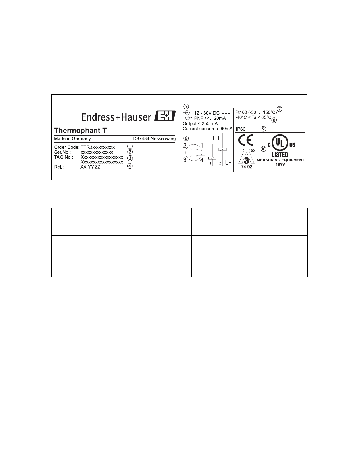
2. 1 Nameplate
To identify your device, compare the complete order code and the version information on the
delivery papers with the data on the nameplate.
T09-TTR31xxx-18-xx-xx-xx-000
Fig. 1: Nameplate for device identification (as example)
!
m Order code r Connection diagram
n Serial number s Measuring range
o TAG number t Ambient temperature
p Release number (change status) u Degree of protection
q Connection values v Approvals
Note!
The release number indicates the change status of the device. A change in the last two figures
does not have any affect on the compatibility - see also → Chap. 7.
4 Endress+Hauser
TTR31, TTR35 Installation
3 Installation
3. 1 Incoming acceptance, storage
• Incoming acceptance:
Check the packaging and the device for damage. Check that the goods delivered are complete
and nothing is missing.
• Storage:
Storage temperature −40 °C to +85 °C (-40 °F to +185 °F).
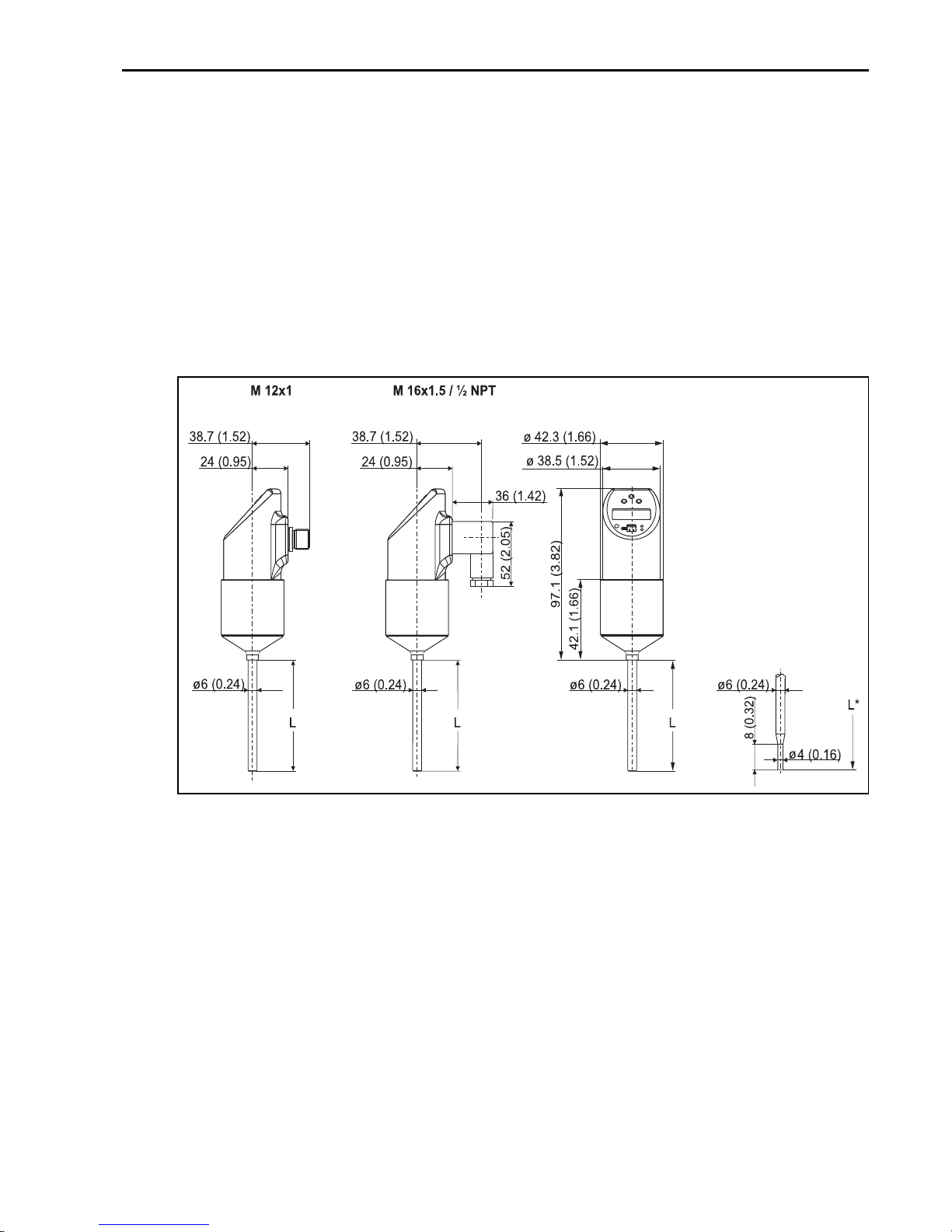
3. 2 Dimensions
Fig. 2: Dimensions in mm (inches)
Version L in 100 and 200 mm (3.94 and 7.87"), version L* = 50 mm (1.97") with reduced sensor tip
M 12x1 connector as per IEC 60947-5-2
M 16x1.5 or ½ NPT valve plug as per DIN 43650A/ISO 4400
Endress+Hauser 5
T09-TTR31xxx-06-xx-xx-en-000
Installation TTR31, TTR35
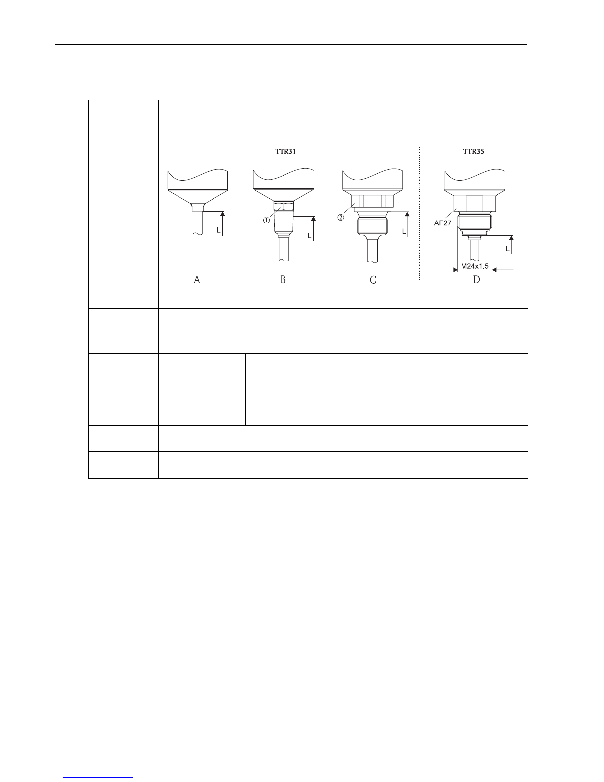
3. 3 Process connection
The following table illustrates the versions of Thermophant T.
TTR31 TTR35
T09-TTR31xxx-17-xx-xx-en-000
Field of application
Process connection
Sensor length L Version L in 100 and 200 mm (3.94 and 7.87"), version L = 50 mm (1.97") only with reduced sensor tip
Measuring range -50 °C to +150 °C (-58 °F to 302 °F)
Version without proc-
ess connection (’w’).
bosses and coupling
Monitoring, display and control of process temperatures Monitoring, display and con-
Item A
Suitable welding
(see Section 6)
Item B
Version with thread
process connection
ANSI ¼" NPT
(m = AF14) and
½" NPT (m = AF27)
Item C
Version with thread
process connection
G ¼A (n = AF14) and
G ½A (n = AF27) as
per ISO 228
trol of process temperatures
in hygienic processes
Adapter concept - version
with M24x1.5 thread for
adapters with process con-
nection for hygienic processes
(see Section 6.1.2)
Item D
6 Endress+Hauser
TTR31, TTR35 Installation
3. 4 Installation instructions
T09-TTR31xxx-11-00-xx-xx-000
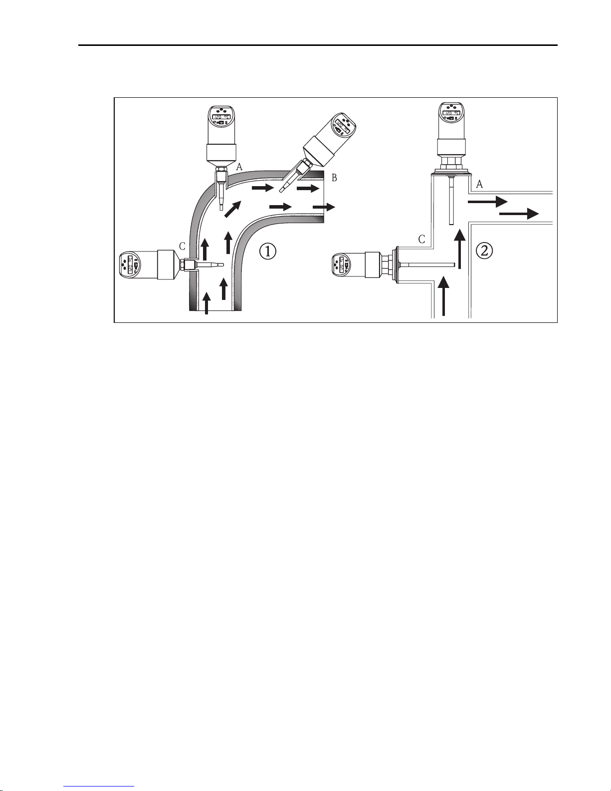
Fig. 3: Possible installation options for temperature monitoring in pipes
m TTR31
n TTR35 for use in hygienic processes
Mounting instructions:
• Installation at angle pieces, against the direction of flow (Fig. 3, Item A)
• Installation in smaller pipes, inclined against the direction of flow (Fig. 3, Item B)
• Installation vertical to the direction of flow (Fig. 3, Item C)
• The on-site display can be rotated electronically 180° − see Section 5. 1 "On-site operation"
• The housing can be rotated up to 310°
Endress+Hauser 7
Wiring TTR31, TTR35
4Wiring
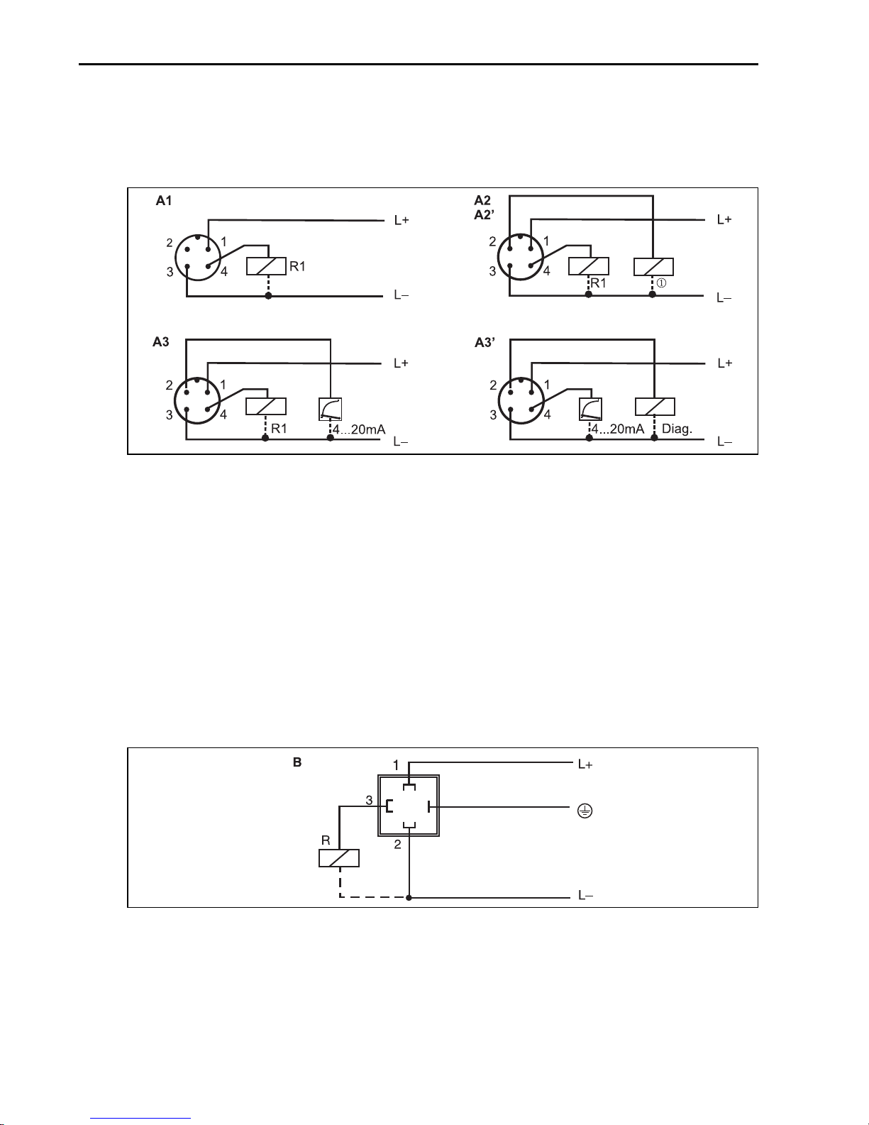
4. 1 DC voltage version with M12 connector
!
P01-PTx3xxxx-04-xx-xx-xx-002
Fig. 4: Thermophant T with M12x1 connector
A1: 1x PNP switch output
A2: PNP switch outputs R1 and m(R2)
A2’: PNP switch outputs R1 and m (diagnosis/break contact with adjustment "DESINA")
A3: PNP switch output with additional analog output
A3’: PNP switch output with additional analog output (PIN assignment with "DESINA" setting)
Note!
DESINA (→ Chap. 5.1.3 Basic settings):
R2 = Diagnosis/break contact (more informations about DESINA see www.desina.de)
4. 2 DC voltage version with valve connector
Fig. 5: Thermophant T with M 16x1.5 or ½ NPT valve plug
B: 1x PNP switch output
8 Endress+Hauser
P01-PTx3xxxx-04-xx-xx-xx-003
TTR31, TTR35 Operation
5 Operation
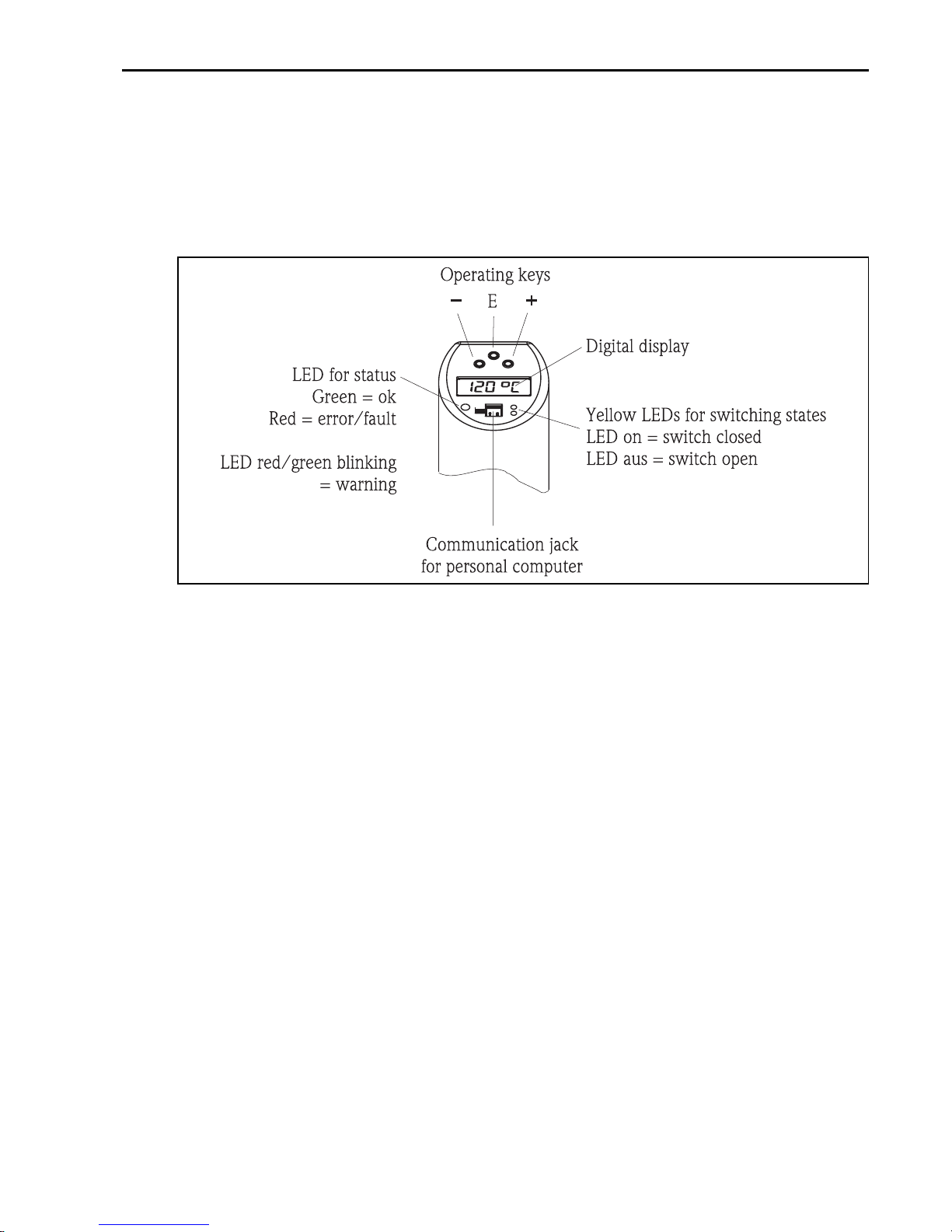
5. 1 On-site operation
The Thermophant T is operated by means of three keys. The digital display and the light emitting
diodes (LED) support navigation in the operating menu.
Fig. 6: Position of operating elements and possibilities for display
Background illumination of the digital display:
– White = OK status
– Red = error status
T09-TTR31xxx-19-xx-xx-en-001
Endress+Hauser 9
 Loading...