

Endress+Hauser Thermocouples TH51, Thermocouples TH52, Thermocouples TH56 Technical Information
Technical Information
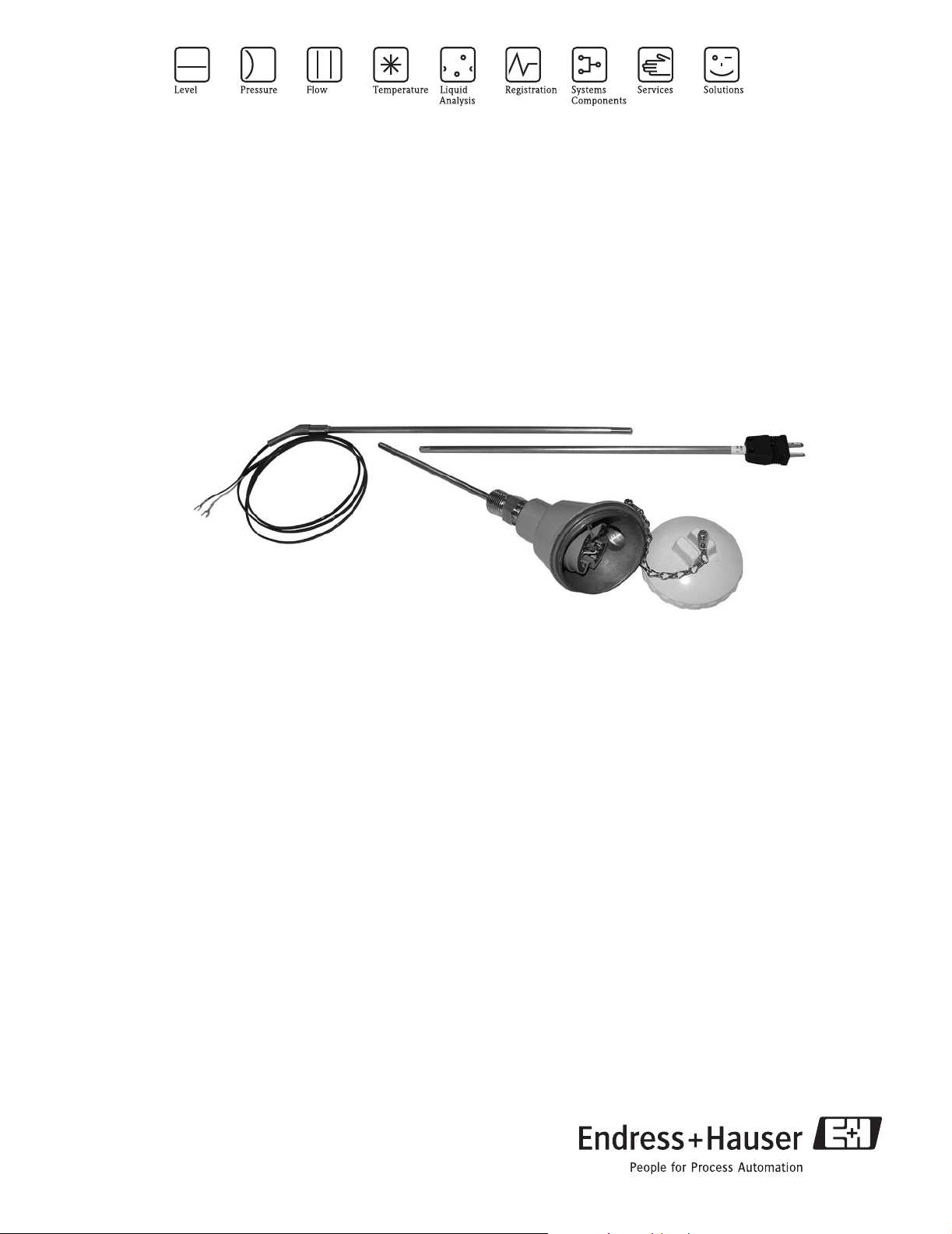
Thermocouples TH51, TH52 & TH56
General purpose MgO insulated thermocouples with connection
head, extension lead wires or connectors for process and laboratory
applications
Areas of application
Magnesium Oxide insulated thermocouples,
commonly referred to as MgO thermocouples, are
used in many process and laboratory applications.
They have many desirable characteristics making
thermocouples a good choice for general and special
purpose applications.
The sensors can be used on:
• Heat exchangers
• Power & recovery areas
• Furnaces
•Dryers
• Flue gas
• Compressor stations
• Process reactors
• Metallurgical and Glass manufacturing
Head transmitters
Instead of directly wiring your temperature sensors to
your control system, use transmitters to reduce
wiring and maintenance costs while increasing
measurement accuracy.
TI111R/24/ae
Your benefits
• One source shopping for temperature measurement
solutions. World class transmitter with integrated sensor
offering.
– Remove and install straight out of the box!
• Improved galvanic isolation on most devices (2 kV)
• Simplified model structure: Competitively priced, offers
great value. Easy to order and reorder. A single model
number includes sensor and transmitter assembly for a
complete point solution.
• All iTEMP
stability ≤ 0.05 % per year
®
transmitters provide long term
TH51, TH52, TH56
Function and system design
Measuring principle The thermocouple sensing element consists of two metal wires that are homogeneous but different from each
other and insulated along their entire length. The two wires are welded together at one end, known as "hot
junction". The other end, where the wires are free, is known as "cold junction" and is connected to an
electromotive force measurement circuit where the force is generated by the different thermoelectric power of
each of the thermocouple wires if there is a temperature difference between the hot junction and the cold
junction (Seebeck effect). The function that links the electromotive force to the temperatures difference is a
curve whose characteristics depend on the materials used in the construction of the thermocouple. The
thermocouples comply with the temperature-electromotive force (EMF) tables of ASTM E-230 and IEC60584
standards.
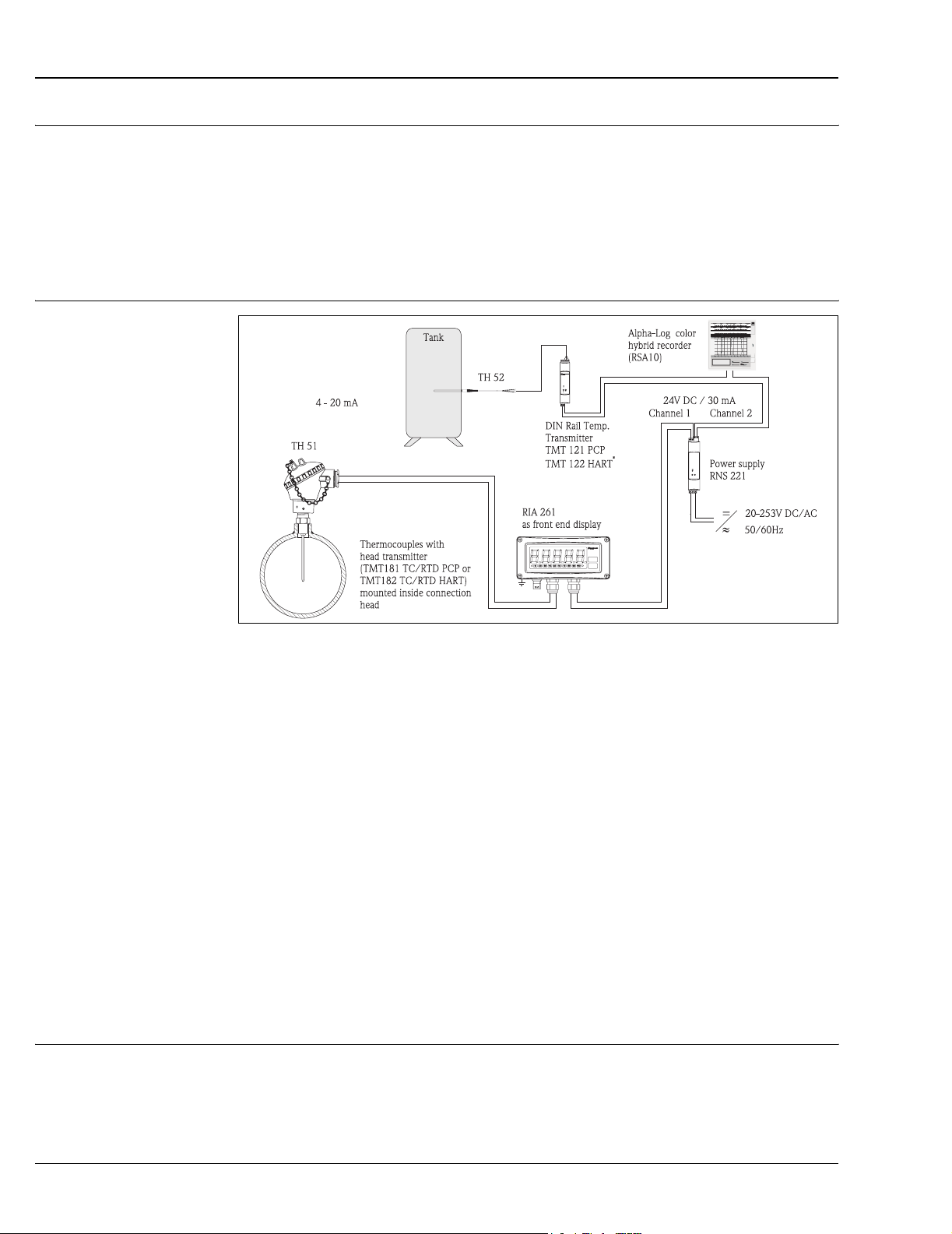
Measuring system
Example of an application of the temperature assemblies
RIA 261 Field display
The display measures an analog measurement signal and indicates this on the display. The display is connected
in a 4 to 20 mA current loop and also derives its supply from the loop. The volt drop is almost negligible
(< 2.5 V). The dynamic internal resistance (load) makes sure that independently from the loop current, the
maximum volt drop is never exceeded. The analog signal at the input is digitalized, analyzed, and shown in
the rear illuminated display. For details see Technical Information (see "Documentation").
RNS 221
The RNS 221S power supply (24 V DC, 30 mA) has two galvanically isolated outputs for supplying voltage to
loop powered transmitters. The two channel power supply has a wide-range input for main power, 20 to
250 V DC/AC, 50/60 Hz to be used in any electrical circuit. For details see Technical Information (see
"Documentation").
RNS 221 is an UL recognized component to UL-3111-1.
Accessory RMA 421A-VN
NEMA 4x protective housing for field mounting DIN rail instruments, see www.us.endress.com/e-direct.
alpha-Log, RSA10
Universal compact panel mounted color hybrid recorder with 1 to 6 analog inputs, automatic wind up system
for 190 ft. (58 m) roll chart paper and informative dual display concept (analog & digital).
Dimensions: 5.7 x 5.7 x 8.5 inches (144x144x215 mm)
For details see Technical Information (see "Documentation").
Equipment architecture MgO thermocouple assemblies consists of a thermocouple element swaged in hard-packed standard purity
(96%) Magnesium Oxide mineral insulation and encased in a metal sheath. Thermocouple sheaths have been
fully annealed; they can be formed into many configurations, and can be bent into a radius of twice the size of
its outer sheath. The hot junction of the thermocouple types according to ASTM E-230 specification are welded
to form a pure joint to ensure highest accuracy and long term stability.
2 Endress+Hauser
TH51, TH52, TH56
Measurement range Measuring range by type and size
Upper Temperature Limits for Various Sheath Diameters °F (°C)
Nominal Diameter Thermocouple Type
Sheath OD Element wire
Dia. (in)
∅ 1/16" 0.010 30 500 °F (260 °C) 825 °F (440 °C) 950 °F (510 °C) 1690 °F (920 °C)
∅ 1/8" 0.020 24 600 °F (315 °C) 970 °F (520 °C) 1200 °F (650 °C) 1960 °F (1070 °C)
∅ 3/16" 0.029 21
∅ 3/8" 0.060 15
Maximum Element
Temperature Range Limits
Element wire
Gauge
TJEKN
700 °F (370 °C)
-454 to 752 °F
(-270 to +400 °C)
1150 °F (620 °C) 1350 °F (730 °C)
1330 °F (720 °C) 1510 °F (820 °C)
-346 to 2192 °F
(-210 to +1200 °C)
-454 to 1832 °F
(-270 to +1000 °C)
2100 °F (1150 °C)∅ ¼" 0.039 19
-454 to 2500 °F
(-270 to +1372 °C)
-454 to 2372 °F
(-270 to +1300 °C)
!
!
Family of temperature transmitters
PC programmable device TMT 181
Note!
These values are valid for single and duplex thermocouples. The temperature limits given are intended only as
a guide to the user and should not be taken as absolute values or as guarantees of satisfactory life or
performance. These types and sizes are sometimes used at temperatures above the given limits, but usually at
the expense of stability or life or both. In other instances, it may be necessary to reduce the above limits in
order to achieve adequate service.
Note!
Duplex versions (2 elements) of Type N with 1/16", 3/16" and 3/8" sheath diameter are not available.
Thermocouples with 316 SS sheath are rated for a maximum temperature of 1700 °F (927 °C).
Electronics
Thermocouple assemblies with iTEMP® transmitters are an installation ready solution to improve the
functionality of temperature measurement by increasing accuracy and reliability when compared to direct
wired sensors. Overall installation costs are lower than with direct wired sensors, since an inexpensive pair of
signal (4 to 20 mA) wires can be run over long distances.
PC programmable devices offer you extreme flexibility and help control costs with the ability to stock one
device and program it for your needs. Regardless of your choice of output, all iTEMP
configured quickly and easily with a PC. To help you with this task, Endress+Hauser offers free software
ReadWin
®
2000 which can be downloaded from our website. Go to www.readwin2000.com to download
ReadWin® 2000 today.
®
transmitters can be
HART® device TMT 182 HART® communication is all about easy, reliable data access and getting better information more
inexpensively. iTEMP
®
transmitters integrate seamlessly into your existing control system and provide painless
access to preventative diagnostic information.
Configuration with a DXR 275 or 375 hand-held or a PC with configuration program (Commuwin II,
ReadWin
Field transmitter TMT 162 Field transmitter with HART
®
2000) or configure with AMS or PDM.
®
communication and blue backlit display. Can be read easily from a distance, in
sunlight and at night. Large measurement value, bargraph and fault indication displayed. Benefits are: dual
sensor input, highest reliability in harsh industrial environments, mathematic functions, thermometer drift
monitoring and sensor back-up functionality, corrosion detection.
Endress+Hauser 3
Performance characteristics
Response time 63% response time per ASTM E839
Junction Style ∅ 1/16" ∅ 1/8" ∅ 3/16" ∅ 1/4" ∅ 3/8"
Grounded 0.3 0.6 0.9 1.3 3.5
Ungrounded 0.4 1.6 2.4 2.9 7.2
TH51, TH52, TH56
!
Maximum measured error Thermocouples corresponding to ASTM E-230.
!
Measurement accuracy transmitter
Note!
Response Time for the sensor assembly without transmitter
Temperature Range Standard Tolerance
Type [°C] [°F] [°C]
E 0 to 870 32 to 1600 ±1.7 or ±0.5% ±1 or ±0.4%
J 0 to 760 32 to 1400 ±2.2 or ±0.75% ±1.1 or ±0.4%
K 0 to 1260 32 to 2300 ±2.2 or ±0.75% ±1.1 or ±0.4%
T 0 to 370 32 to 700 ±1 or ±0.75% ±0.5 or ±0.4%
N 0 to 1260 32 to 2300 ±2.2 or ±0.75% ±1.1 or ±0.4%
Note!
For measurement errors in °F, calculate using equation above in °C, then multiply the outcome by 1.8.
Transmitter
TMT 181 multifunctional PCP TMT 182 HART
0.36 °F (0.2 °C) or 0.08%
1
0.36 °F (0.2 °C) or 0.08%
(IEC Class 2)
(whichever is greater)
®
1
Special Tolerance
(IEC Class 1)
[°C]
(whichever is greater)
TMT 162 HART® Field Transmitter
≤ 0.19 °F (0.105 °C)
1) % is related to the adjusted measurement range (the larger value applies)
Transmitter long-term stability
≤ 0.18 °F / year (≤ 0.1 °C / year) or ≤ 0.05% / year
Data under reference conditions; % is related to the set span. The larger value applies.
4 Endress+Hauser
TH51, TH52, TH56
Insulation resistance Insulation resistance for MgO insulated thermocouples with ungrounded hot junction between terminals and
probe sheath, test voltage 500 Vdc.
• 1,000 MΩ at 77 °F (25 °C)
These values for insulation resistance apply also between each thermocouple wire at single and duplex
constructions with ungrounded hot junction.
Galvanic isolation Galvanic isolation of Endress+Hauser iTEMP® transmitters (input/output)
Transmitter type Sensor
TMT 181 PCP Û = 3.75 kV AC
TMT 182 HART
TMT 162 HART
In applications where fast response time is needed, grounded thermocouples are recommended. This
thermocouple design may cause a ground loop. This can be avoided by using iTEMP transmitters with high
galvanic isolation.
®
®
Field transmitter U = 2 kV AC
U = 2 kV AC
Wiring
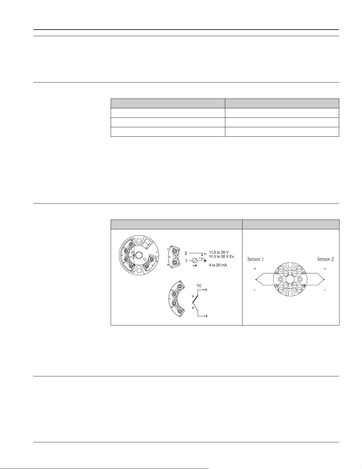
Wiring diagrams Type of sensor connection TH51
Head transmitter mounted Terminal block mounted
!
!
Note!
TH52 is available only with conductor external lead wires, DIN rail transmitters (TMT 121 PCP / TMT 122
®
) are available, see 'Documentation'.
HART
Note!
The blocks and transmitters are shown as they sit inside the heads in reference to the conduit opening.
T09-TH5156xx-04-xx-XX-ae-000
T09-TH5156xx-04-xx-XX-ae-001
Wire specifications TH51
Thermocouple grade, TFE insulated 20AWG, 7 strands with wire termination
Endress+Hauser 5
TH51, TH52, TH56
TH52
All thermocouple extension wires are thermocouple grade.
Sheath OD No of elements Extension wire (gauge)
∅ 1/16"
∅ 1/8"
∅ 3/16"
∅ ¼"
∅ 3/8"
Thermocouple wire types, Construction and Characteristics
124
224
120
224
120
224
120
220
120
220
Single conductor Duplex conductor Max. conti-
Insulation Impregnation Insulation Impregnation
0.006"
0.008"
Silicone modified resin
/ FEP extruded
Glass braid
0.006"
0.010"
Silicone modified resin
/ 400 °F
!
Type
Fiberglass Glass Braid
Teflon FEP extruded
Note!
Flex armor is 0.272" nominal OD, 304SS 0.010" thick, square lock style.
TH52 is also available with connector, see section "Connector style".
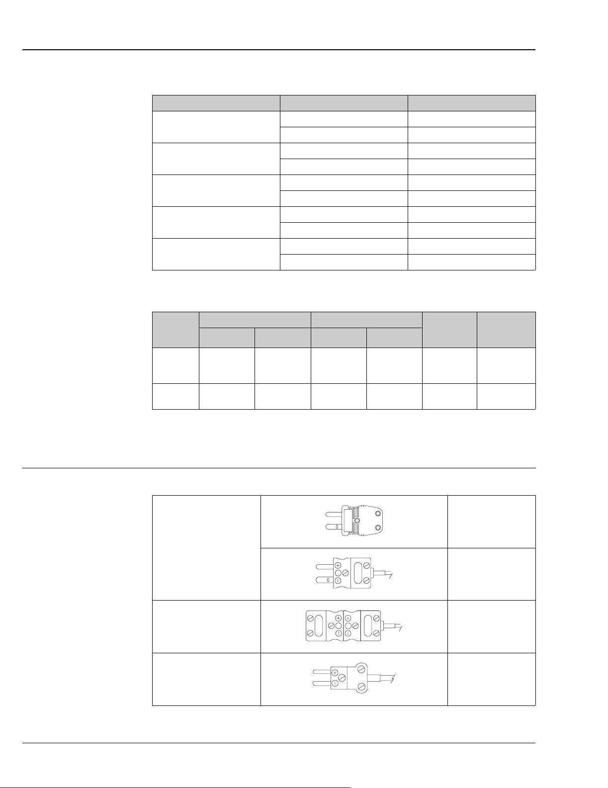
Connector style Type of connectors TH52 and TH56, standard and miniature plugs
A = STANDARD
B = STANDARD W/ FEMALE
nuous temperature
900 °F
(482 °C)
(204 °C)
T09-TH5156xx-04-xx-XX-ae-009
T09-TH5156xx-04-xx-XX-ae-008
Notes
Impregnation
retained to
400 °F (204 °C)
max. 350 °F
TH52, all types J and K
TH56, types J and K
3/16" and ¼" only
max. 350 °F
All Others!
max. 350 °F
T09-TH5156xx-04-xx-XX-ae-003
C = MINI
T09-TH5156xx-04-xx-XX-ae-004
max. 350 °F
6 Endress+Hauser
 Loading...