

Page 1
Technical Information
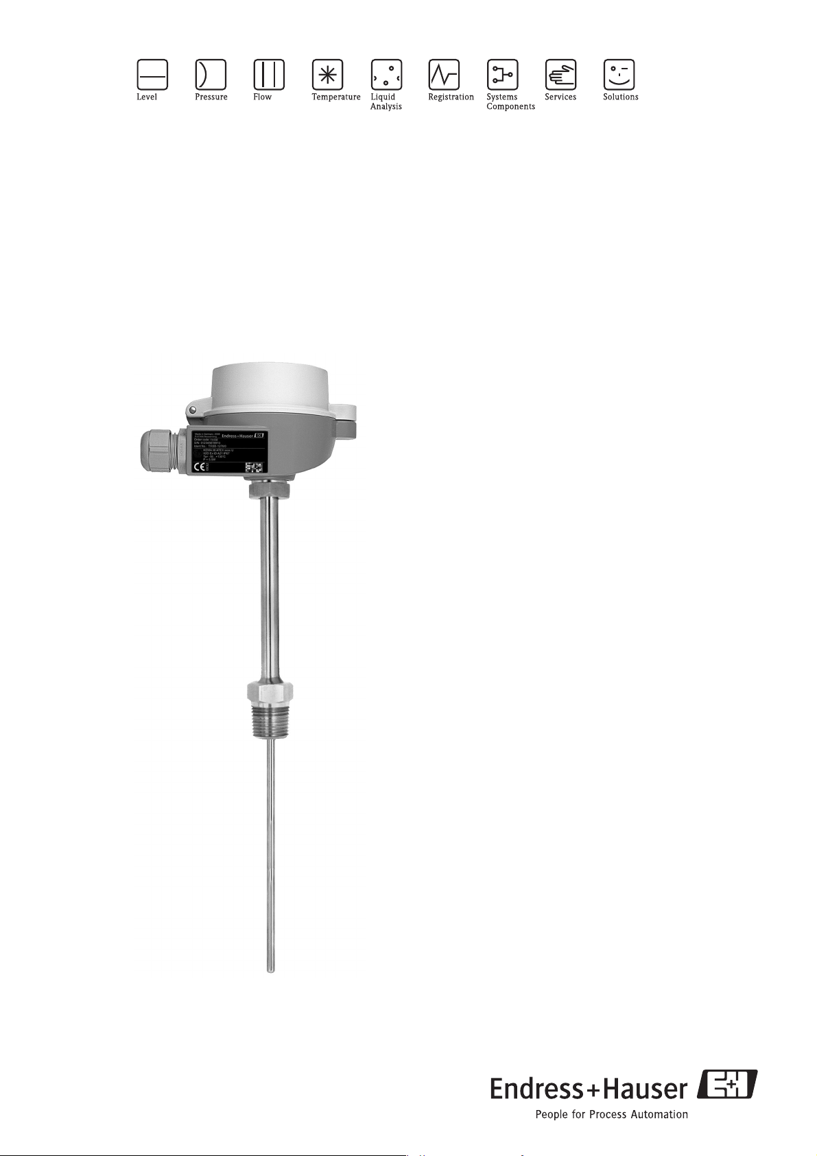
Omnigrad S TR88
Modular RTD assembly
Extension neck and threaded connection for installation in an
existing thermowell
Application
• Universal application
• Suitable for installation in already existing
thermowells
• Measuring range: -200 to +600 °C (-328 to +1112 °F)
• Installation without thermowell possible in
unpressurized processes
• Degree of protection up to IP 68
• Replaceable insert
Head transmitters
All Endress+Hauser transmitters are available with
enhanced accuracy and reliability compared to directly
wired sensors. Easy customizing by choosing one of the
following outputs and communication protocols:
• Analog output 4...20 mA
•HART
•PROFIBUS® PA
• FOUNDATION Fieldbus™
®
Your benefits
• High degree of flexibility thanks to modular design
with standard terminal heads and customer-specific
immersion lengths
• Variable total length in suitable thermowells thanks to
compression fitting on extension neck
• Types of protection for use in hazardous locations:
Intrinsic Safety (Ex ia)
Non-sparking (Ex nA)
4 0
TI271T/02/en
71107907
Page 2
TR88
Function and system design
Measuring principle These resistance thermometers use a Pt100 temperature sensor according to IEC 60751. This temperature
sensor is a temperature-sensitive platinum resistor with a resistance of 100 Ω at 0 °C (32 °F) and a temperature
coefficient α = 0.003851 °C
There are generally two different kinds of platinum resistance thermometers:
• Wire wound (WW): Here, a double coil of fine, high-purity platinum wire is located in a ceramic support.
This is then sealed top and bottom with a ceramic protective layer. Such resistance thermometers not only
facilitate very reproducible measurements but also offer good long-term stability of the resistance/
temperature characteristic within temperature ranges up to 600 °C (1112 °F). This type of sensor is relatively
large in size and it is comparatively sensitive to vibrations.
• Thin film platinum resistance thermometers (TF): A very thin, ultrapure platinum layer, approx. 1 μm
thick, is vaporized in a vacuum on a ceramic substrate and then structured photolithographically. The
platinum conductor paths formed in this way create the measuring resistance. Additional covering and
passivation layers are applied and reliably protect the thin platinum layer from contamination and oxidation
even at high temperatures.
The primary advantages of thin-film temperature sensors over wire wound versions are their smaller sizes and
better vibration resistance. A relatively low principle-based deviation of the resistance/temperature
characteristic from the standard characteristic of IEC 60751 can frequently be observed among TF sensors at
high temperatures. As a result, the tight limit values of tolerance category A as per IEC 60751 can only be
observed with TF sensors at temperatures up to approx. 300 °C (572 °F). For this reason, thin-film sensors are
generally only used for temperature measurements in ranges below 400 °C (932 °F).
-1
.
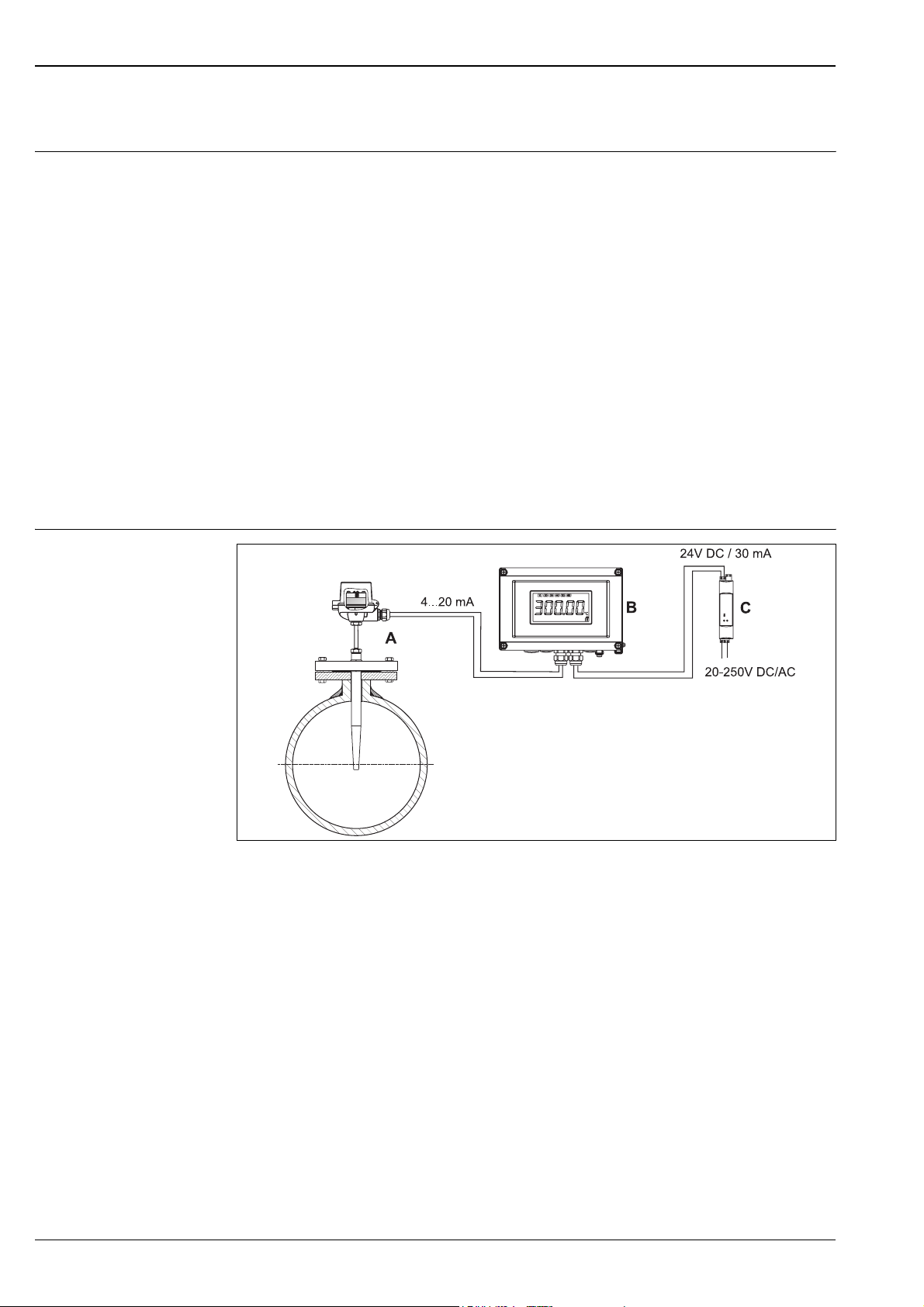
Measuring system
a0012641
Example of an application
A Thermometer with fitted head transmitter mounted in an existing onsite thermowell
B RIA16 field display unit
– The display unit records the analog measuring signal from the head transmitter and shows this on the display. The
LC display shows the current measured value in digital form and as a bar graph indicating a limit value violation. The
display unit is looped into the 4 to 20 mA circuit and gets the required energy from there. More information on this
can be found in the Technical Information (see "Documentation").
C Active barrier RN221N
– The RN221N active barrier (24 V DC, 30 mA) has an galvanically isolated output for supplying voltage to loop
powered transmitters. The universal power supply works with an input supply voltage of 20 to 250 V DC/AC, 50/
60 Hz, which means that it can be used in all international power grids. More information on this can be found in
the Technical Information (see "Documentation").
2 Endress+Hauser
Page 3
TR88
Equipment architecture
a0012672
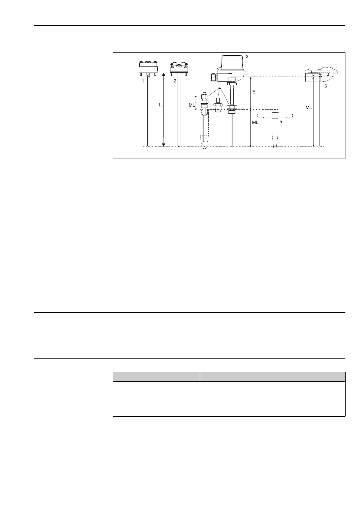
Thermometer design
12Insert (∅ 3 mm, 0.12 in) with mounted
head transmitter (example)
Insert (∅ 6 mm, 0.24 in) with mounted
ceramic connection socket (example)
34Terminal head
Thermowell connection: Threaded connection or
compression fitting on extension neck
The resistance thermometers from the Omnigrad S TR88 series have a modular design. The terminal head is
used as a connection module for the mechanical and electrical connection of the insert. The actual sensor
element of the resistance thermometer sits in the insert and is mechanically protected. If installed in a
thermowell, the insert can be replaced and calibrated directly in the process. Either ceramic connection sockets
or transmitters can be mounted on the internal connection socket.
The TR88 is designed for installation in an existing onsite thermowell. Different threaded connections are
available on the bottom of the extension neck for installation in the thermowell. Insofar as the thermowell is
suited to this purpose, the thermometer may also be mounted using a suitable compression fitting on the
extension neck. This means that thermometers with a fixed insertion length can be used variably, even in
thermowells of varying length, and can be installed in such a way that an optimum thermal contact is
guaranteed between the tip of the insert and the bottom of the thermowell.
Measurement range -200...+600 °C (-328...+1112 °F)
Performance characteristics
5
Existing onsite thermowell located in the process
6
Version without extension neck, if thermowell and
extension neck are present on site in the process
E
Length of extension neck
ILMLTotal length of insert = ML + E + 10 mm (0.4 in)
Insertion length for existing onsite components
Operating conditions Ambient temperature
Terminal head Temperature in °C (°F)
Without mounted head transmitter Depends on the terminal head used and the cable gland or fieldbus connec-
With mounted head transmitter -40 to 85 °C (-40 to 185 °F)
With mounted head transmitter and display -20 to 70 °C (-4 to 158 °F)
tor, see 'Terminal heads' section, → ä 8
Process pressure
The maximum process pressure depends on the thermowell into which the thermometer is screwed. For an
overview of the Endress+Hauser thermowells which may be used, see → ä 17.
Endress+Hauser 3
Page 4
Permitted flow rate as a function of immersion length
The maximum permitted flow rate to which the thermometer can be subjected, reduces the greater the
immersion depth of the thermowell in the flowing medium. In addition, it is dependent on the diameter of the
tip of the thermowell, the medium type, process temperature and process pressure. For an overview of the
Endress+Hauser thermowells which may be used, see → ä 17.
Shock and vibration resistance
3g / 10 to 500 Hz as per IEC 60751 (RTD-Thermometer)
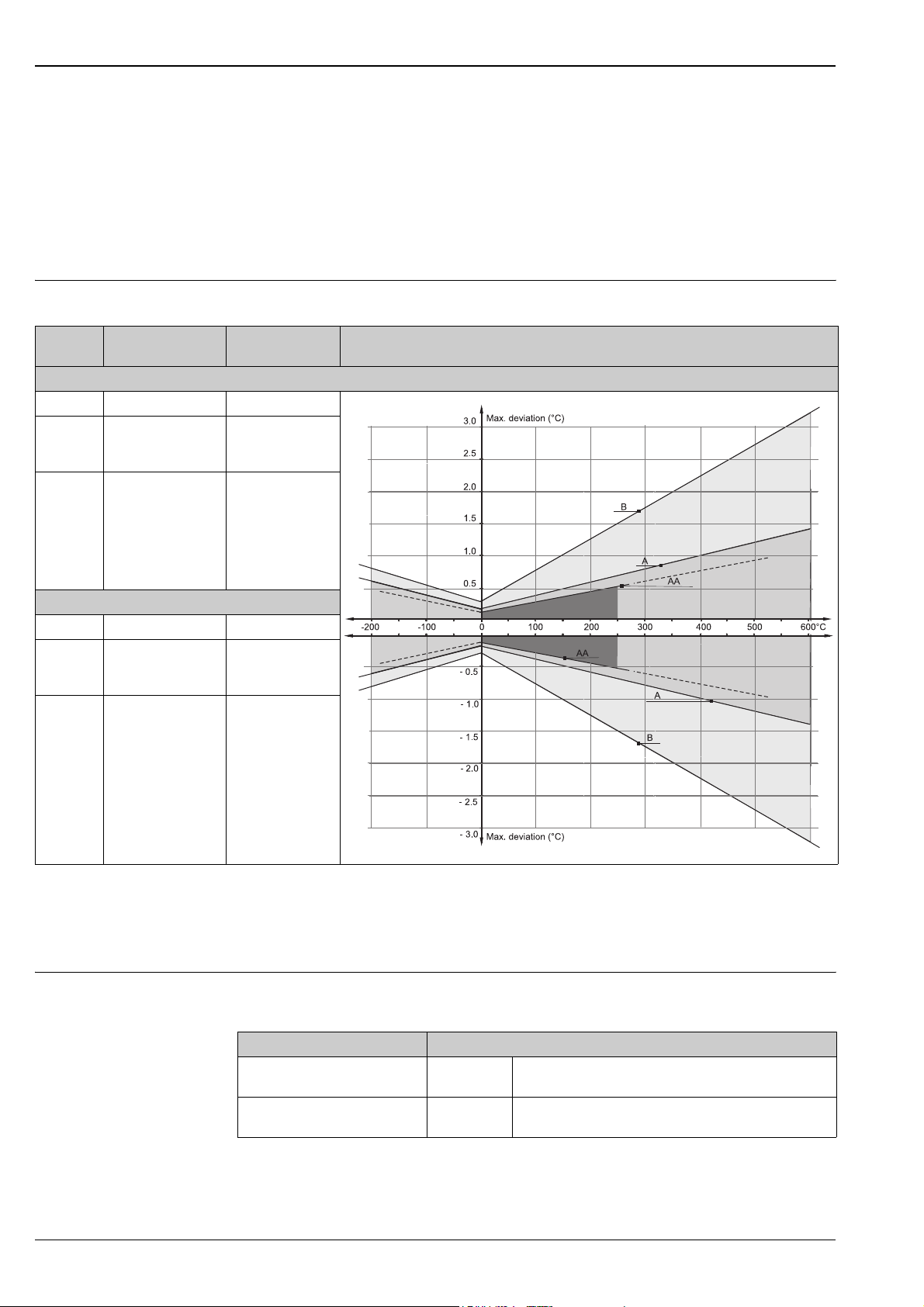
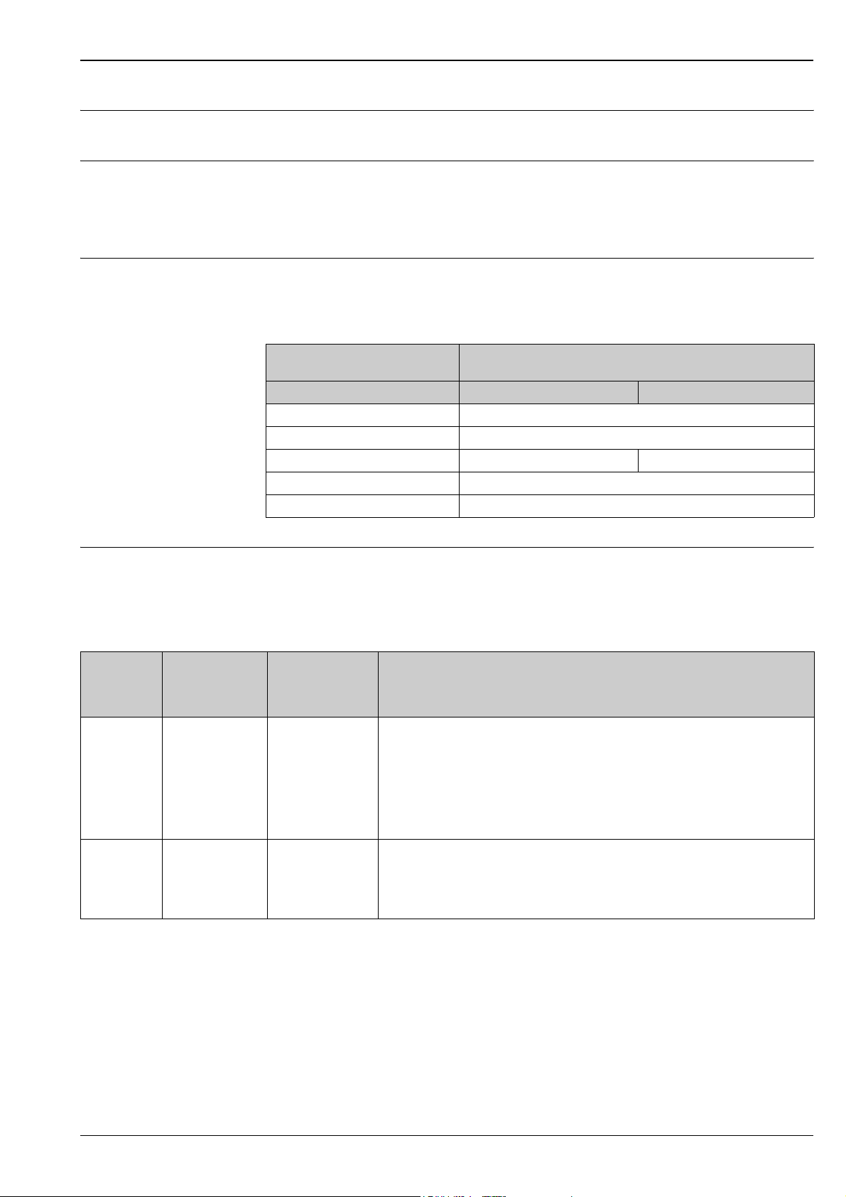
Accuracy RTD corresponding to IEC 60751
TR88
Class max. Tolerances
(°C)
RTD max. error type TF - range: -50 to +400 °C
Cl. A ± (0.15 + 0.002 · |t|
Cl. AA,
former 1/3
Cl. B
Cl. B ± (0.3 + 0.005 · |t|
RTD max. error type WW - range: -200 to +600 °C
Cl. A ± (0.15 + 0.002 · |t|
Cl. AA,
former
1/3 Cl. B
Cl. B ± (0.3 + 0.005 · |t|
± (0.1 + 0.0017 · |t|
± (0.1 + 0.0017 · |t|
Temperature range Characteristics
1)
) -50 °C to +250 °C
1)
) 0 °C to +150 °C
1)
) -50 °C to +400 °C
1)
) -200 °C to +600 °C
1)
) 0 °C to +250 °C
1)
) -200 °C to +600 °C
a0008588-en
1) |t| = absolute value °C
!
Note!
For measurement errors in °F, calculate using equations above in °C, then multiply the outcome by 1.8.
Response time Tests in water at 0.4 m/s (1.3 ft/s), according to IEC 60751; 10 K temperature step change. Measuring probe
Pt100, TF/WW:
Insert diameter Response time
3.5 s
8 s
2 s
5 s
!
6 mm (0.24 in) t
3 mm (0.12 in) t
50
t
90
50
t
90
Note!
Response time for RTD insert without transmitter.
4 Endress+Hauser
Page 5
TR88
Insulation resistance Insulation resistance ≥100 MΩ at ambient temperature.
Insulation resistance between each terminal and the sheath is measured with a voltage of 100 V DC.
Self heating RTD elements are passive resistances that are measured using an external current. This measurement current
causes a self heating in the RTD element itself which in turn creates an additional measurement error. In
addition to the measurement current the size of the measurement error is also affected by the temperature
conductivity and flow velocity of the process. This self heating error is negligible when an Endress+Hauser
®
temperature transmitter (very small measurement current) is connected.
iTEMP
Calibration specifications Endress+Hauser provides comparison temperature calibration from -80 to +600 °C (-110 °F to 1112 °F) based
on the International Temperature Scale (ITS90). Calibrations are traceable to national and international
standards. The calibration report is referenced to the serial number of the thermometer. Only the measurement
insert is calibrated.
Insert-Ø:
6 mm (0.24 in) and 3 mm (0.12 in)
Temperature range without head transmitter with head transmitter
-80 °C to -40 °C (-110 °F to -40 °F) 200 (7.87)
-40 °C to 0 °C (-40 °F to 32 °F) 160 (6.3)
0 °C to 250 °C (32 °F to 480 °F) 120 (4.72) 150 (5.9)
250 °C to 550 °C (480 °F to 1020 °F) 300 (11.81)
550 °C to 650 °C (1020 °F to 1202 °F) 400 (15.75)
Material Neck, measuring insert.
The temperatures for continuous operation specified in the following table are only intended as reference values
for use of the various materials in air and without any significant compressive load. The maximum operation
temperatures are reduced considerably in some cases where abnormal conditions such as high mechanical load
occur or in aggressive media.
Material name Short form Recommended max.
AISI 316L/
1.4404
1.4435
AISI 316Ti/
1.4571
X2CrNiMo17-12-2
X2CrNiMo18-14-3
X6CrNiMoTi17-12-2 700 °C (1292 °F)
temperature for
continuous use in
air
650 °C (1200 °F)
1)
1)
Minimum insertion length IL in mm (inch)
Properties
• Austenitic, stainless steel
• High corrosion resistance in general
• Particularly high corrosion resistance in chlorine-based and acidic, non-oxidizing atmospheres
through the addition of molybdenum (e.g. phosphoric and sulfuric acids, acetic and tartaric
acids with a low concentration)
• Increased resistance to intergranular corrosion and pitting
• Compared to 1.4404, 1.4435 has even higher corrosion resistance and a lower delta ferrite
content
• Properties comparable to AISI316L
• Addition of titanium means increased resistance to intergranular corrosion even after welding
• Broad range of uses in the chemical, petrochemical and oil industries as well as in coal
chemistry
• Can only be polished to a limited extent, titanium streaks can form
1) Can be used to a limited extent up to 800 °C (1472 °F) for low compressive loads and in non-corrosive media. Please contact your Endress+Hauser sales team
for further information.
Endress+Hauser 5
Page 6
Transmitter specifications
TR88
TMT180
PCP
Pt100
Measurement accuracy 0.2 °C (0.36 °F), optional
0.1 °C (0.18 °F) or 0.08%
% is related to the adjusted measurement range (the larger value applies)
Sensor current I ≤ 0.6 mA I ≤ 0.2 mA I ≤ 0.3 mA
Galvanic isolation (input/output) - Û = 2 kV AC
TMT181
PCP
Pt100, TC, Ω, mV
0.2 °C (0.36 °F) or 0.08% 0.1 °C (0.18 °F)
TMT182
®
HART
Pt100, TC, Ω, mV
TMT84 PA / TMT85 FF
Pt100, TC, Ω, mV
Components
Family of temperature transmitters
Thermometers fitted with iTEMP® transmitters are an installation ready complete solution to improve
temperature measurement by increasing accuracy and reliability, when compared to direct wired sensors, as
well as reducing both wiring and maintenance costs.
PC programmable head transmitter TMT180 and TMT181
They offer a high degree of flexibility, thereby supporting universal application with low inventory storage. The
®
transmitters can be configured quickly and easily at a PC. Endress+Hauser offers the ReadWin® 2000
iTEMP
configuration software for this purpose. This software can be downloaded free of charge at
www.readwin2000.com. More information can be found in the Technical Information (see
"Documentation" section).
®
TMT182 head transmitter
HART
®
HART
communication is all about easy, reliable data access and getting additional information about the
measurement point more inexpensively. iTEMP
®
system and provide painless access to numerous diagnostic information.
Configuration with a hand-held (Field Xpert SFX100 or DXR375) or a PC with configuration program
(FieldCare, ReadWin
®
2000) or configure with AMS or PDM. Details see Technical Information (see chapter
’Documentation’).
Type of transmitter Specification
®
iTEMP
TMT18x
PROFIBUS
R09-TMT182ZZ-06-06-xx-en-001
®
PA TMT84 head transmitter
• Material: Housing (PC), Potting (PUR)
• Terminals: Cable up to max. ≤ 2.5 mm
wire end ferrules
• Eyelets for easy connection of a HART
clips
• Degree of protection NEMA 4 (see also type of terminal head)
Details see Technical Information (see chapter ’Documentation’)
Universally programmable head transmitter with PROFIBUS
signals into a digital output signal. High accuracy over the complete ambient temperature range. Swift and easy
operation, visualization and maintenance using a PC directly from the control panel, e. g. using operating
software such as FieldCare, Simatic PDM or AMS.
Benefits are: dual sensor input, highest reliability in harsh industrial environments, mathematic functions,
thermometer drift monitoring, sensor back-up functionality, sensor diagnosis functions and sensor-transmitter
matching using Callendar-Van Dusen coefficients. Details see Technical Information (see chapter
’Documentation’).
transmitters integrate seamlessly into your existing control
2
/ 16 AWG (secure screws) or with
®
-handheld terminal with alligator
®
PA communication. Converting various input
6 Endress+Hauser
Page 7

TR88
FOUNDATION Fieldbus™ TMT85 head transmitter
Universally programmable head transmitter with FOUNDATION Fieldbus™ communication. Converting
various input signals into a digital output signal. High accuracy over the complete ambient temperature range.
Swift and easy operation, visualization and maintenance using a PC directly from the control panel, e. g. using
operating software such as ControlCare from Endress+Hauser or the NI Configurator from National
Instruments.
Benefits are: dual sensor input, highest reliability in harsh industrial environments, mathematic functions,
thermometer drift monitoring, sensor back-up functionality, sensor diagnosis functions and sensor-transmitter
matching using Callendar-Van Dusen coefficients. Details see Technical Information (see chapter
’Documentation’).
Type of transmitter Specification
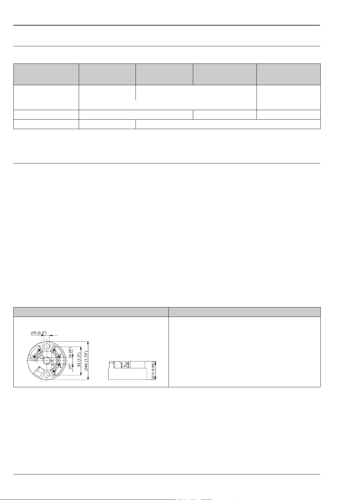
iTEMP® TMT84 and TMT85
Pluggable display TID10 as option
• Spring range L ≥ 5 mm (0.2"), see Pos. A
• Fixing elements for pluggable measured value display, see Pos. B
• Interface for contacting measured value display, see Pos. C
• Material (RoHS-compliant)
Housing: PC
Potting: PU
•Terminals:
Screw terminals (cable up to max. ≤ 2.5 mm
or spring terminals (e. g. from 0.25 mm
for flexible wires with wire-end ferrules with plastic ferrule)
• Degree of protection NEMA 4 (see also type of terminal head)
a0007301-en
Details see Technical Information (see chapter ’Documentation’)
• Displays the actual measured value and the measurement point identification
• Displays fault events in inverse color with channel ident and diagnostics code
• DIP-switches on the rear for hardware set-up, e. g. PROFIBUS
address
Note!
!
Display is only available with suitable terminal head with display window, e.g.
TA30
2
/ 16 AWG)
2
to 0.75 mm2/ 24 AWG to 18 AWG
®
PA bus
a0009955
Endress+Hauser 7
Page 8

Terminal heads All terminal heads have an internal shape and size in accordance with DIN EN 50446, flat face and a
thermometer connection of M24x1.5.
All dimensions in mm (inch). The cable glands in the diagrams correspond to M20x1.5 connections.
Specifications without head transmitter installed. For ambient temperatures with head transmitter installed, see
’Operating conditions’ section.
TA30A Specification
• Degree of protection: IP66/68
• Max. temperature: 150 °C (300 °F)
• Material: aluminum, polyester powder coated
Seals: silicone
• Cable entry incl. glands: ½" NPT and M20x1.5, only thread: G ½",
plugs: M12x1 PA, 7/8" FF
• Protection armature connection: M24x1.5
• Head color: blue RAL 5012
• Cap color: grey RAL 7035
• Weight: 330 g (11.64 oz)
a0009820
TR88
TA30A with display window Specification
• Degree of protection: IP66/68
• Max. temperature: 150 °C (300 °F)
• Material: aluminum, polyester powder coated
Seals: silicone
• Cable entry incl. glands: ½" NPT and M20x1.5, only thread: G ½",
plugs: M12x1 PA, 7/8" FF
• Protection armature connection: M24x1.5
• Head color: blue RAL 5012
• Cap color: grey RAL 7035
• Weight: 420 g (14.81 oz)
• Head transmitter optional with TID10 display
a0009821
TA30D Specification
• Degree of protection: IP66/68
• Max. temperature: 150 °C (300 °F)
• Material: aluminum, polyester powder coated
Seals: silicone
• Cable entry incl. glands: ½" NPT and M20x1.5, only thread: G ½",
plugs: M12x1 PA, 7/8" FF
• Protection armature connection: M24x1.5
• Two head transmitters can be mounted. In the standard version,
one transmitter is mounted in the terminal head cover and an
additional terminal block is installed directly on the insert.
• Head color: blue RAL 5012
• Cap color: grey RAL 7035
• Weight: 390 g (13.75 oz)
a0009822
8 Endress+Hauser
Page 9

TR88
TA20B Specification
• Degree of protection: IP65
• Max. temperature: 80 °C (176 °F)
• Material: polyamide (PA)
• Cable entry: M20x1.5
• Head and cap color: black
• Weight: 80 g (2.82 oz)
®
marked
•3-A
a0008663
TA21E Specification
• Degree of protection: IP65
• Max. temperature: 130 °C (266 °F) silicone, 100 °C (212 °F)
rubber (observe max. permitted temperature of the cable gland!)
• Material: aluminum alloy with polyester or epoxy coating; rubber
or silicone seal under the cover
• Cable entry: M20x1.5 or plug M12x1 PA
• Protection armature connection: M24x1.5, G ½" or NPT ½"
• Head color: blue RAL 5012
• Cap color: grey RAL 7035
• Weight: 300 g (10.58 oz)
®
marked
•3-A
a0008669
TA20J Specification
• Degree of protection: IP66/IP67
• Max. temperature: 70 °C (158 °F)
• Material: 316L (1.4404) stainless steel, rubber seal under the
cover (hygienic design)
• 4 digits 7-segments LC display (loop powered with 4...20 mA
transmitter)
• Cable entry: ½" NPT, M20x1.5 or plug M12x1 PA
• Protection armature connection: M24x1.5 or ½" NPT
• Head and cap color: stainless steel, polished
• Weight: 650 g (22.93 oz) with display
• Humidity: 25 to 95%, no condensation
®
marked
•3-A
The programming is executed through 3 keys at the bottom of the
display.
a0008866
* dimensions with optional display
Endress+Hauser 9
Page 10

TA20R Specification
• Degree of protection: IP66/67
• Max. temperature: 100 °C (212 °F)
• Material: SS 316L (1.4404) stainless steel
• Cable entry: ½" NPT, M20x1.5 or plug M12x1 PA
• Head and cap color: stainless steel
• Weight: 550 g (19.4 oz)
•LABS - free
®
marked
3-A
a0008667
Maximum ambient temperatures for cable glands and fieldbus connectors
Type Temperature range
Cable gland ½" NPT, M20x1.5 (non Ex) -40 to +100 °C (-40 to +212 °F)
Cable gland M20x1.5 (for dust ignition-proof area) -20 to +95 °C (-4 to +203 °F)
Fieldbus connector (M12x1 PA, 7/8" FF) -40 to +105 °C (-40 to +221 °F)
TR88
Design, dimensions All dimensions in mm (inch).
a0012662
ABInsert with mounted terminal block
Insert with mounted head transmitter
∅ ID Insert diameter
6 mm (0.24 in) or 3 mm (0.12 in)
C Insert with flying leads E Length of extension neck
D Model without extension neck, intended fo
mounting in an existing onsite extension neck
r
IL
ML
Total length of insert = ML + E + 10 mm (0.4 in)
Insertion length
10 Endress+Hauser
Page 11

TR88
Weight From 0.5 to 2.5 kg (1 to 5.5 lbs) for standard options.
Process connection The thermometer is designed for installation in an existing onsite thermowell or in a thermowell which can be
ordered separately. The installation is done using the threaded connection on the bottom of the extension neck
or using a compression fitting.
Threaded connection Version Thread length
TL in mm (inch)
Cylindrical (version M, G, R) Conical (version NPT) M M14x1.5
M18x1.5 24
GG½" as per
ISO 6149
NPT NPT ½" as per
ANSI B1.20.1
R R ¾", JIS B
0203
R ½", JIS B
0203
a0008620
E = Length of extended neck
ML, L = Insertion length, immersion length
12 (0.47)
15 (0.6) 27
8 (0.32)
Width across
flats AF
17
22
27
22
Compression fitting
The insert is pushed through a coupling together with the extension neck, Ø 12 mm (0.47 in), and secured
using a clamping ring made of 316L stainless steel. The clamping ring can not be reused. The compression
fitting must be secured again using a new clamping ring. The insertion length is completely adjustable.
Process connection compression fitting with thread
• Can be used in the case of thermowells with a sufficiently large internal
bore, Ø > 12 mm (0.47 in), to hold the extension neck.
• Coupling may be used only in unpressurized processes.
a0012642
K = Clamping ring
Spare parts • The RTD insert is available as spare part TPR100 (see "Documentation" section in the Technical
Information).
If the insert is required as a spare part, please note the following formula:
Total length of insert IL = ML + E + 10 mm (0.4 in)
• Extension neck welded with threaded connection to terminal head. DIN flat face, different connections to
separate thermowell, order number TN15-...
• Compression fitting with thread, Ø 12 mm (0.47 in), process connection thread G½", clamping ring made
of 316L stainless steel, order number TA50-KC
Endress+Hauser 11
Page 12

Wiring
Wiring diagrams Type of sensor connection
Head mounted transmitter TMT18x (single input)
TR88
T09-TH1112xx-04-xx-XX-ae-000
Head mounted transmitter TMT84 and TMT85 (dual input)
Terminal block mounted
a0008848-en
a0008591-en
12 Endress+Hauser
Page 13

TR88
Installation conditions
Orientation No restrictions.
Installation instructions
The thermometer is designed for installation in an
existing thermowell or in a thermowell which can be
ordered separately. Different threaded connections to
suit the thermowell are available on the
thermometer's extension neck (→ ä 11).
The necessary insertion length (ML) of the insert
depends on the total length of the thermowell (A) and
the type of thermowell used. It can be freely selected
within the range of 100 to 5000 mm (3.94 and 197
in). Longer insertion lengths are available on request.
The same also applies when ordering an insert as a
spare part. More detailed information on determining
the insertion length (ML) required in each case can be
found in the following table (applies to
Endress+Hauser thermowells with standard base
thicknesses).
a0012639
Thermometer installation
Type of
thermowell
TA535 ML = A TW15 ML = A TA570
TA540 ML = A - 2 (0.08) TA560
TA550 ML = A - 3 (0.12) TA562 TA572
TA555
TA557 TA566 TA576 ML = A - 2 (0.12)
ML in mm (inch) Type of
ML = A - 2 (0.08)
thermowell
TA565 TA575
ML in mm (inch) Type of
thermowell
TA571
ML = A - 3 (0.12)
ML in mm (inch)
ML = A - 3 (0.12)
In the case of thermowells with a noncompliant standard base thickness (D), the following formula must be
used: ML = A - D + 3 (0.12) in mm (inch).
Endress+Hauser 13
Page 14

Neck tube length The neck tube is the part between the process connection and the terminal head.
As illustrated in the following figure, the neck tube length may influence the temperature in the terminal head.
It is necessary that this temperature is kept within the limit values defined in the chapter "Operating
conditions".
TR88
a0011769-en
Heating of the terminal head consequent to the process temperature
Temperature in terminal head = ambient temperature 20 °C (68 °F) + ΔT
Certificates and approvals
CE Mark The device meets the legal requirements of the EC directives if applicable. Endress+Hauser confirms that the
device has been successfully tested by applying the CE mark.
Hazardous area approvals For further details on the available Ex versions (ATEX, CSA, FM, etc.), please contact your nearest
Endress+Hauser sales organization. All relevant data for hazardous areas can be found in separate Ex
documentation. If required, please request copies.
Other standards and
guidelines
• IEC 60529:
Degrees of protection by housing (IP-Code).
• IEC 61010-1:
Safety requirements for electrical measurement, control and laboratory instrumentation.
• IEC 60751:
Industrial platinum resistance thermometer
• DIN43772:
Thermowells
• DIN EN 50446, DIN 47229:
Terminal heads
• IEC 61326-1:
Electromagnetic compatibility (EMC requirements)
PED approval The thermometer complies with paragraph 3.3 of the Pressure Equipment Directive (97/23/CE) and is not
marked separately.
Test report and calibration The "Factory calibration" is carried out according to an internal procedure in a laboratory of Endress+Hauser
accredited by the European Accreditation Organization (EA) to ISO/IEC 17025. A calibration which is
performed according to EA guidelines (SIT or DKD calibration) may be requested separately. The calibration is
performed on the replaceable insert of the thermometer. In the case of thermometers without a replaceable
insert, the entire thermometer - from the process connection to the tip of the thermometer - is calibrated.
14 Endress+Hauser
Page 15

TR88
Ordering information
Product structure This information provides an overview of the order options available. The information is not exhaustive,
however, and may not be fully up to date. More detailed information is available from your local
Endress+Hauser representative.
RTD Thermometer TR88
Approval:
A Non-hazardous area
B ATEX II 1 GD Ex ia IIC
E ATEX II 1/2 GD Ex ia IIC
G ATEX II 1 G Ex ia IIC
H ATEX II 3 GD EEx nA II
K TIIS Ex ia IIC T4
L TIIS Ex ia IIC T6
Head; Cable entry:
B TA30A Alu, IP66/IP68; M20
C TA30A Alu, IP66/IP68; NPT ½"
D TA30A Alu, IP66/IP67; M12 plug PA
E TA21E Alu, screw cap IP65; M20
F TA30A Alu+Display, IP66/IP68; M20
G TA30A Alu+Display, IP66/IP68; NPT ½"
H TA30A Alu+Display, IP66/IP67; M12 plug PA
I TA30A Alu, G½" w/o gland
J TA20J 316L, IP66/IP67; M20
K TA20J 316L, display, IP66/IP67; M20
L TA30A Alu +Display; G1/2" w/o gland
M TA20J 316L, IP66/IP67; M12 plug PA
O TA30D Alu, high cover, IP66/IP68; M20
P TA30D Alu, high cover, IP66/IP68; NPT ½"
Q TA30D Alu, IP66/IP67; M12 plug PA
R TA20R 316L screw cap IP66/IP67; M20
S TA20R 316L screw cap IP66; M12 plug
T TA30A Alu, IP66/IP67; 7/8" plug FF
U TA30A Alu+Display, IP66/IP67; 7/8" plug FF
V TA30D Alu, IP66/IP67; 7/8" plug FF
3 TA30D Alu, high cover; G½" w/o gland
7 TA20B PA black, IP65; M20
Extension E:
0 w/o neck
1 80 mm
2 100 mm
3 155 mm
4 165 mm
5 200 mm
8 ..... mm
9 ..... mm, as specified
Process connection:
A Thread M14x1.5, 316Ti
B Thread M18x1.5, 316Ti
C Thread G½", 316Ti
E Thread ½" NPT, 316Ti
F Compression fitting G½"
G Thread R ¾", JIS B 0203, 316Ti
H Thread R ½", JIS B 0203, 316Ti
Y Special version, TSP-no. to be specified
0 not needed
Neck diameter; Material:
1 11 mm; 316Ti
2 w/o neck to build in on side existing neck
3 12 mm; 316 Ti
Insertion length ML:
A 110 mm
B 140 mm
C 170 mm
Endress+Hauser 15
Page 16

Insertion length ML:
D 200 mm
E 260 mm
F 410 mm
X ..... mm
Y ..... mm, as specified
1 100 mm
2 160 mm
3 400 mm
Insert diameter; Material:
1 3mm; 316L
2 6mm; 316L
Head transmitter; Range:
B TMT84 PA
C Terminal block
D TMT85 FF
F Flying leads
G TMT181 (PCP); temperature range to be specified
H TMT182 (HART, SIL2); temperature range to be specified
K TMT182 (HART), diagnostic, advanced
2 TMT180-A21 fix; 0.2 K, temperature range to be specified, span limit -200/650 °C
3 TMT180-A22 fix; 0.1 K, temperature range to be specified, span limit -50/250 °C
4 TMT180-A11 PCP; 0.2 K, temperature range to be specified, span limit -200/650 °C
5 TMT180-A12 PCP; 0.1 K, temperature range to be specified, span limit -50/250 °C
RTD; wire; measurement range; class; validity:
A 1x Pt100 WW; 3; -200/600 °C; A: -200/600 °C
B 2x Pt100 WW; 3; -200/600 °C; A: -200/600 °C
C 1x Pt100 WW; 4; -200/600 °C; A: -200/600 °C
F 2x Pt100 WW; 3; -200/600 °C; 1/3B; 0/250 °C
G 1x Pt100 WW; 3; -200/600 °C; 1/3B; 0/250 °C
Y Special version, TSP-no. to be specified
2 1x Pt100 TF; 3; -50/400 °C; A; -50/250 °C increased vibration resistance
3 1x Pt100 TF; 4; -50/400 °C; A; -50/250 °C increased vibration resistance
6 1x Pt100 TF; 3; -50/400 °C; 1/3B; 0/150 °C increased vibration resistance
7 1x Pt100 TF; 4; -50/400 °C; 1/3B; 0/150 °C increased vibration resistance
Material certificate:
0 Not needed
9 Special version, TSP-no. to be specified
Factory test:
A 0, 100 °C, RTD-Signal
B 0, 100 °C, RTD-Signal, 4-20 mA/loop
C 0, 100 °C, RTD-Signal, 2 Sensors
E 0, 100, 150 °C, RTD-Signal
F 0, 100, 150 °C, RTD-Signal, 4-20 mA/loop
G 0, 100, 150 °C, RTD-Signal, 2 Sensors
0 not needed
1 Inspection RTD-Signal
2 Inspection RTD-Signal, 4-20 mA/loop
Additional option:
0 not needed
9 Special version, TSP-no. to be specified
TR88- ← Order code (complete)
TR88
16 Endress+Hauser
Page 17

TR88
Documentation
Technical Information:
• RTD Insert for Temperature Sensor Omniset TPR100 (TI268t/02/en)
• Temperature head transmitter:
–iTEMP
–iTEMP
–iTEMP® HART® TMT182 (TI078r/09/en)
–iTEMP® TMT84 PA (TI138r/09/en)
–iTEMP
Technical Informations thermowells:
Type of thermowell
TA535 TI250t/02/en TW15 TI265t/02/en TA570 TI161t/02/en
TA540 TI166t/02/en TA560 TI159t/02/en TA571 TI178t/02/en
TA550 TI153t/02/en TA562 TI230t/02/ TA572 TI179t/02/en
TA555 TI154t/02/en TA565 TI160t/02/en TA575 TI162t/02/
TA557 TI156t/02/en TA566 TI177t/02/en TA576 TI163t/02/
®
PCP TMT181 (TI070r/09/en)
®
Pt TMT180 (TI088r/09/en)
®
TMT85 FF (TI134r/09/en)
Hazardous area supplementary documentation:
• Omnigrad TRxx RTD Thermometer ATEX II1GD or II 1/2GD (XA072r/09/a3)
• Omnigrad TRxx/TCxx RTD/TC Thermometer ATEX II 3GD (XA044r/09/a3)
Application example Technical Information:
• Field display RIA16 (TI144r/09/en)
• Active barrier with power supply RN221N (TI073R/09/en)
Endress+Hauser 17
Page 18

TR88
18 Endress+Hauser
Page 19

TR88
Endress+Hauser 19
Page 20

TR88
Instruments International
Endress+Hauser
Instruments International AG
Kaegenstrasse 2
4153 Reinach
Switzerland
Tel. +41 61 715 81 00
Fax +41 61 715 25 00
www.endress.com
info@ii.endress.com
TI271T/02/en/11.09
71107907
FM+SGML 6.0 ProMoDo
 Loading...