

Page 1

TI00151K/09/EN/02.13
71241091
Products Solutions Services
Technical Information
EngyCal® RH33
BTU meter
Custody transfer BTU meter for recording and
billing the heat/cold quantity given off by water,
water/glycol mixtures or other liquids
Transparent energy consumption helps you save on
energy costs
Application
Recording and billing the quantities of heat and cold in:
•Heating circuits
• Cooling circuits
• Combined heating and cooling circuits
Typical application areas in industry, long-distance heat networks and building automation.
Your benefits
• Verified and certified reliability and accuracy
• Standard models are suitable for connecting and supplying all common volume flow
transmitters and temperature measuring points
• Detailed data logging of current and counter values and of error messages, off-limit
conditions and changes to operating parameters
• Industry-compliant compact housing for field or wall mounting, panel mounting or
top-hat rail mounting
• Deficit counter for transparency in case of error or alarm
• Custody transfer logbook enables versatile device configuration in the field
• Tariff counter for requirements-based billing
• Calibrated, electronically paired temperature sensors ensure the highest accuracy
and enable replacement of individual temperature sensors even for certified devices
in the field (without reapproval!)
• Remote readout via Ethernet and fieldbuses
Page 2

EngyCal® RH33
q
T
warm
T
cold
Function and system design
Measuring principle The EngyCal® RH33 BTU meter is used to measure the heat and cold in systems with liquid heat trans-
fer fluids. It is easy to install and read. Thanks to its verified long-term stability and high-precision
measurements, the device helps optimize processes and control costs in the process. Comprehensive
data analysis options in the Field Data Manager software MS20 (see accessories) identify potential
areas for cost reduction.
Measuring system
Measuring system with EngyCal ® RH33, 2x paired temperature sensors and flow sensor
Functions Energy calculation
EngyCal
®
RH33 calculates the thermal energy of water, glycol/water mixtures or other liquids such as
thermal oils in accordance with EN1434.
Calculation basis: IAWPS-IF97
Calculated values:
• Power
•Volume
•Density
• Enthalpy & enthalpy differential
• DP flow compensation
•Mass
• Temperature differential
Counters
Volume, mass, energy, deficit
Optional: tariff1, tariff2 or separate heat/cold energy, balance energy
Fault mode / deficit counter
The fault mode of the EngyCal
error value). Thanks to the defined fault mode and the separate deficit counter, the device guarantees
transparency for energy calculation and documentation for billing.
For the case of further calculation with an error value, the total calculated energy during the error condition is counted on a deficit counter.
In this case, the output continues to supply the calculated energy value. If values are communicated via
buses, these are given the value "invalid". Optionally, an alarm relay can be switched.
a0013618-en
®
RH33 can be defined freely (no further calculation or calculation with
User-defined heat transfer media
Heat transfer media in cooling circuits usually consist of glycol-water mixtures. Mixtures for the following glycols are already predefined in the EngyCal®:
• Ethylene-glycol
•Antifrogen N
• Glykosol N
•Propylene glycol
For these glycol-water mixtures it is possible to enter the glycol concentration for accurate calculations.
If other heat transfer media are used (e.g. thermal oils, cooling agents), the liquid data must be programmed into the device. Tables are available for this purpose in which the user can enter the density
2 Endress+Hauser
Page 3

EngyCal® RH33
and thermal capacity (max. 10 support points). For devices with the "DP Flow Measurement" option,
another table with two support points is available for entering the viscosity data.
The values between or outside the support points are determined by interpolation or extrapolation.
Temperature sensor matching in the device
®
The temperature sensors are paired internally in the EngyCal
RH33 by storing the sensor characteristic curves via Callendar-van-Dusen coefficients. The Callendar-van-Dusen coefficients are determined by calibrating the temperature sensor.
The internal alignment function makes it possible to use unpaired sensors, and to replace one sensor
independently of the second sensor while maintaining or improving accuracy levels (compared to using
paired sensors).
Compensation of differential pressure flow measurement
The flow calculation according to the differential pressure method is a special form of flow measurement. Volume or mass flow values measured according to the DP method require a specific correction.
The iterative solution of the calculation equations listed there allow the best possible accuracy (ca. 0.6
– 1 %) to be attained for DP flow measurements.
Compensation of flow measurement for throttle methods (orifice plate, nozzle).
The measurement (orifice plate, nozzle, Venturi pipe) is carried out according to ISO5167. Flow measurements according to the dynamic pressure method are determined according to the relationship
between the differential pressure and flow.
Data logging and logbook
Event logbook:
The EngyCal RH33
®
BTU meter has a logbook for measured values and a logbook for events.
In the event logbook, all parameter changes, off-limit conditions, alarms and other events are documented with timestamp such that they are tamper-proof. At minimum, the last 1600 events are stored
in non-volatile memory.
The data logging allows process values and calculated values, as well as counters, to be stored in freely
definable intervals. Predefined analyses (Day, Month, Year, Billing dates) support the transparency of
the process and ensure a quick overview of all consumption values.
All entries into the event logbook and the logged data can be read out automatically via the visualization software (Field Data Manager Software) and backed up in an SQL database so that it is tamperproof.
For fast and easy-to-understand analysis in case of service, an internal diagnostic memory with
occurred error messages is also available.
Analysis No. of analyses
Interval (1min) Approx. 700
Day 260 days
Month/year/billing date 17 years
Events At least 1600 (depending on the length of the message text)
Approval for custody transfer and custody transfer logbook
The device is equipped with a custody transfer switch, which disables configuration ranges that are relevant for custody transfer.
The custody transfer switch is located inside the device. The housing is lead-sealed.
The switch is enabled before delivery if the device is ordered with approval for custody transfer. Following this, it is possible to reconfigure relevant device settings three times. All changes to the parameters are logged in the custody transfer logbook and time-stamped.
The switch can only be reset by the manufacturer.
Thus the seamless documentation enables versatile commissioning and parameter configuration of
the computer in the field (without loss of custody transfer approval).
Limit value monitoring
Three limits can be assigned as desired the following measured and calculated values:
Volume flow, temperature, pressure, mass flow, power (heat flow), density, enthalpy, operating volume, heat and tariff 1, tariff 2
Endress+Hauser 3
Page 4

EngyCal® RH33
In case of violation of the defined limits, an entry is made into the event logbook. In addition, relays
can be switched and the off-limit condition can be indicated in the display. Limits are also visible via
the integrated Web server.
Bidirectional measurement (optional)
®
EngyCal
RH33 enables bidirectional measurement, i.e. the combined measurement of heat and cold,
for example when charging/discharging a heat accumulator, including calculation of the quantities of
heat. The bidirectional measurement can be flow-dependent or temperature-dependent.
This option cannot be combined with the tariff function.
A digital input can be used to detect the flow direction.
Tariff counters (optional)
The tariff counters enable analysis and recording of the energy on an additional counter.
Two types of tariff counter are available: A defined tariff can be activated by an event or via the digital
inputs. If the defined event occurs, the calculated energy is counted at this tariff.
Tariff counters enable, for example, invoicing on specific billing dates (due date invoicing), requirements-based billing (daytime/nighttime tariff) and analysis of counters when reaching set points, e.g.
power-dependent.
Various tariff models are available for selection in the device, e.g. Energy; Power, warm; Power, cold;
Time.
The standard counters continue running at the same time, e.g. they are not affected by the activation
of the tariff counters.
This option cannot be combined with the bidirectional measurement function.
Real time clock (RTC)
The device has a real time clock that can be synchronized via a free digital input or using the Field Data
Manager software MS20.
The real time clock continues running even in case of a power failure, the device documents power on
and off; the clock switches automatically or (optionally) manually from daylight saving to standard
time.
Display
To display measured values, counters and calculated values, 6 groups are available. Each group can be
assigned up to 3 values or meter readings as desired.
Analyzing the stored data - Field Data Manager software MS20
The Field Data Manager Software allows the stored measured values, alarms and events, and the
device configuration to be read out from the device (automatically) so that they are tamper-proof and
stored securely in an SQL database. The software offers centralized data management with a variety of
visualization functions. Using an integrated system service, analyses and reports can be created,
printed and stored fully automatically. Security is provided by the FDA-compliant audit trail of the software and the extensive user management. Simultaneous access and analysis of data from various
workstations or users is supported (client-server architecture).
4 Endress+Hauser
Page 5

EngyCal® RH33
Input
Current/pulse input Th is inp ut can b e u sed eithe r a s a c urren t inpu t f or 0 /4 to 2 0 mA sig nals (n ot if th e appr oval fo r c ust ody
transfer option has been selected) or as a pulse/frequency input.
The input is galvanically isolated (500 V testing voltage towards all other inputs and outputs).
Cycle time
The cycle time is 250 ms or 500 ms respectively when using one or two RTD inputs.
Reaction time
In the case of analog signals, the reaction time is the time between the change at the input and the
time when the output signal is equivalent to 90% of the full scale value. The reaction time is lengthened
by 250 ms if an RTD with 3-wire measurement is connected.
Input Output Reaction time [ms]
Current Current ≤ 600
Current Relay/digital output ≤ 600
RTD Current/ relay/digital output ≤ 600
Cable open circuit detection Current/ relay/digital output ≤ 600
Cable open circuit detection, RTD Current/ relay/digital output ≤ 1100
Pulse input Pulse output ≤ 600
Current input
Measuring range: 0/4 to 20 mA + 10 % over range
Accuracy: 0.1 % of full scale value
Temperature drift: 0.01 %/K (0.0056 %/°F) of the full scale value
Loading capacity: Max. 50 mA, max. 2.5 V
Input impedance (load): 50 Ω
®
signals Not affected
HART
A/D converter resolution: 20 bit
Pulse/frequency input
The pulse/frequency input can be configured for different frequency ranges:
• Pulses and frequencies up to 12.5 kHz
• Pulses and frequencies up to 25 Hz (filters out bounce contacts, max. bounce time: 5 ms)
Minimum pulse width:
Range up to 12.5 kHz
Range up to 25 Hz
Maximum permissible contact bounce time:
Range up to 25 Hz 5 ms
Pulse input for active voltage pulses and contact sensors as per EN 1434-2, Class IB and IC:
Non-conductive state
Conductive state
No-load supply voltage: 3 V to 6 V
Current limiting resistance in the power supply
(pull-up at input): 50 kΩ to 2 MΩ
Maximum permissible input voltage: 30 V (for active voltage pulses)
40 μs
20 ms
≤ 1 V
≥ 2 V
Endress+Hauser 5
Page 6

EngyCal® RH33
Pulse input for contact sensors as per EN 1434-2, Class ID and IE:
Low-level
High-level
No-load supply voltage: 7 V to 9 V
Current limiting resistance in the power supply
(pull-up at input):
Not suitable for active input voltages.
Current/pulse input:
Low-level
High-level
Loading capacity: Max. 50 mA, max. 2.5 V
Input impedance (load): 50 Ω
Accuracy during frequency measurement:
Basic accuracy: 0.01 % of measured value
Temperature drift: 0.01 % of measured value over entire temperature range
≤ 1.2 mA
≥ 2.1 mA
562 Ωto 1 kΩ
≤ 8 mA
≥ 13 mA
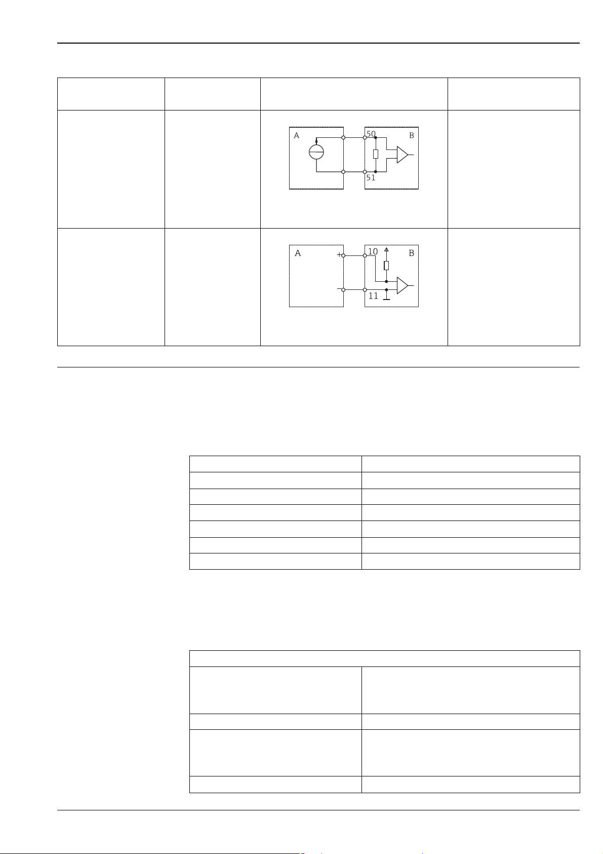
Pulse output of the flow
RH33 setting Electrical connection Remark
sensor
Mechanical contact Pulse ID/IE up to25 Hz
Open Collector (NPN) Pulse ID/IE up to 25 Hz
or up to 12.5 kHz
Active voltage Pulse IB/IC+U
A Sensor
B RH33
A Sensor
B RH33
"Pulse IB/IC+U" up to 25 Hz can
also be used. The current through
the contact is lower then (approx.
0.05 mA instead of 9 mA).
Advantage: less load;
disadvantage: lower interference
resistance.
A0015354
"Pulse IB/IC+U" can also be used.
The current through the contact is
lower then (approx. 0.05 mA
instead of 9 mA). Advantage: less
load; disadvantage: lower
interference resistance.
A0015355
The switching threshold is
between 1 V and 2 V
A0015356
A Sensor
B RH33
6 Endress+Hauser
Page 7
EngyCal® RH33
Pulse output of the flow
RH33 setting Electrical connection Remark
sensor
Active current Pulse I
The switching threshold is
between 8 mA and 13 mA
A0015357
A Sensor
B RH33
Namur sensor (as per
EN60947-5-6)
Pulse ID/IE up to 25 Hz
or up to 12.5 kHz
A Sensor
B RH33
A0015359
No monitoring for short circuit is
carried out.
2 x current/RTD input These inputs can be used either as current inputs (0/4 to 20 mA; not if the approval for custody trans-
fer option has been selected) or as resistance temperature detector (RTD = resistance thermometer)
inputs. It is also possible to configure one input as a current input and the other as an RTD input.
The two inputs are galvanically connected but galvanically isolated from the other inputs and outputs
(testing voltage: 500 V).
Current input
Measuring range: 0/4 to 20 mA + 10 % over range
Accuracy: 0.1 % of full scale value
Temperature drift: 0.01 %/K (0.0056 %/°F) of the full scale value
Loading capacity: Max. 50 mA, max. 2.5 V
Input impedance (load): 50 Ω
A/D converter resolution: 24 bit
®
signals are not affected.
HART
RTD input
Pt100, Pt500 and Pt1000 resistance temperature detectors can be connected to this input.
Endress+Hauser resistance temperature detectors, type TR10, are optionally available - see ordering
information.
Measuring ranges:
Pt100_exact:
Pt100_wide:
Pt500:
Pt1000:
Connection method: 2-, 3- or 4-wire connection
Accuracy: 4-wire:
Temperature drift: 0.01 %/K (0.0056 %/°F) of the measuring range
-200 °C to 300 °C (-328 to 572 °F)
-200 °C to 600 °C (-328 to 1112 °F)
-200 °C to 300 °C (-328 to 572 °F)
-200 °C to 300 °C (-328 to 572 °F)
0.06% of measuring range
3-wire:
0.06% of measuring range + 0.8 K (1.44 °F)
Endress+Hauser 7
Page 8

Delta T measurement (differential measurement
between
both RTD inputs):
Characteristic curves: DIN EN 60751:2008 IPTS-90
Max. cable resistance: 40 Ω
Cable open circuit detection: Outside the measuring range
0.03 °C (0.054 °F)
Digital inputs Two digital inputs are available for switching the following functions.
Digital input 1 Digital input 2
Activate tariff counter 1
Time synchronization
Lock device (Block set up)
Activate tariff counter 2
Change flow direction
Time synchronization
Lock device (Block set up)
Input level:
To IEC 61131-2 type 3:
Logical "0" (corresponds to -3 to +5 V), activation with logical "1" (corresponds to +11 to +30 V)
EngyCal® RH33
Input current:
Max. 3.2 mA
Input voltage:
Max. 30 V (steady-state, without destroying the input)
8 Endress+Hauser
Page 9
EngyCal® RH33
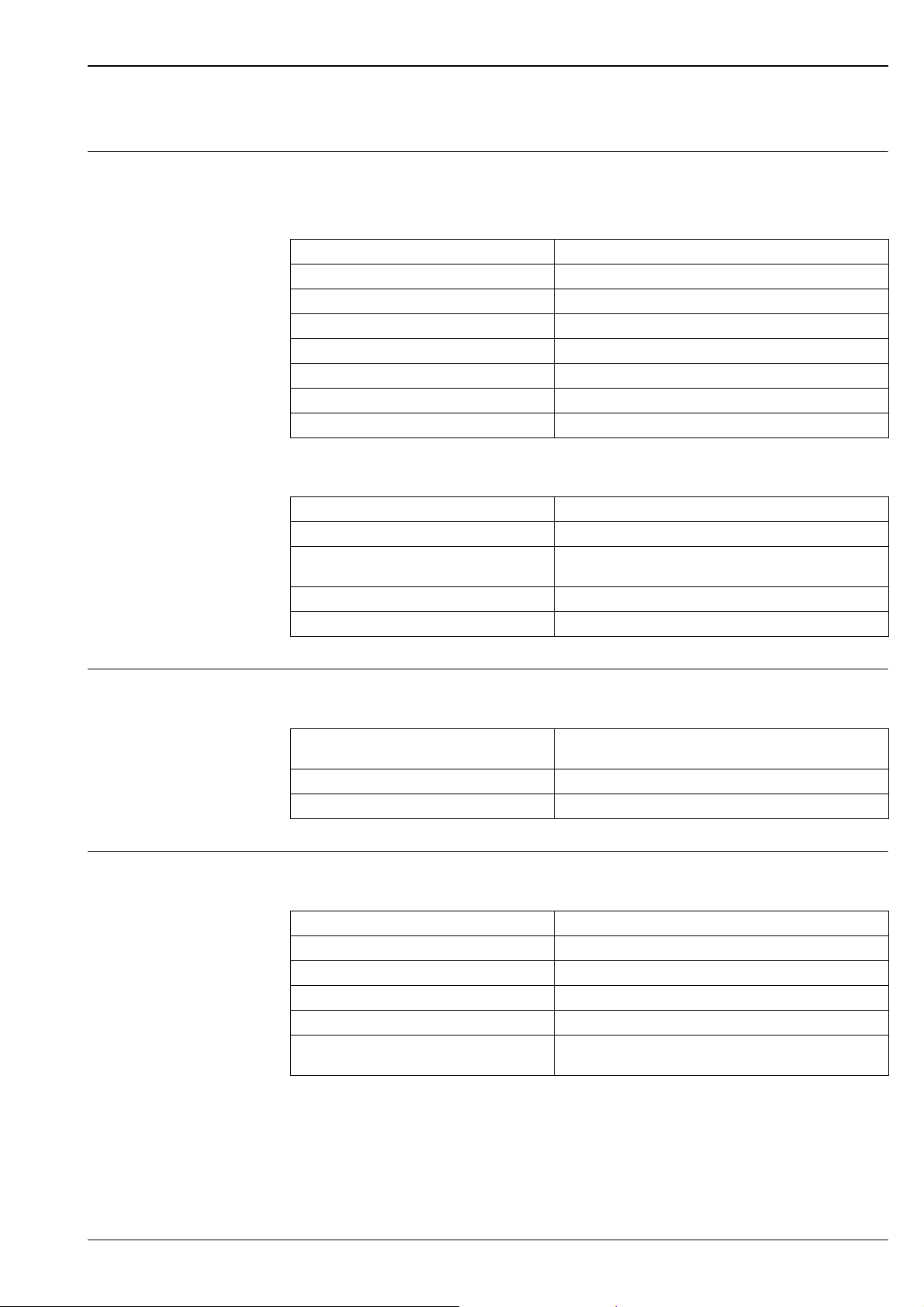
Output
Current/pulse output (option)
This output can be used either as a 0/4 to 20 mA current output or as a voltage pulse output. The output is galvanically isolated (500 V testing voltage towards all other inputs and outputs).
Current output
Output range: 0/4 to 20 mA + 10 % over range
Load: 0 to 600 Ω (as per IEC 61131-2)
Accuracy: 0.1 % of full scale value
Temperature drift: 0.01 %/K (0.0056 %/°F) of the full scale value
Inductive load: Max. 10 mH
Capacitance load: Max. 10 μF
Ripple: Max. 12 mVpp on 600 Ω for frequencies < 50 kHz
D/A converter resolution: 14 bit
Pulse output
Frequency: Max. 12.5 kHz
Pulse width: Min. 40 μs
Voltage level: Low: 0 to 2 V
High: 15 to 20 V
Maximum output current: 22 mA
Short-circuit proof
2 x relay output The relays are designed as NO contacts. The output is galvanically isolated (1500 V testing voltage
towards all other inputs and outputs).
2 x digital output, open collector (option)
Max. relay switching capacity: AC: 250 V, 3 A
Minimum contact load: 10 V, 1 mA
Min. switching cycles: >10
The two digital inputs are galvanically isolated from one another and from all the other inputs and outputs (testing voltage: 500 V). The digital outputs can be used as status or pulse outputs.
Frequency: Max. 1 kHz
Pulse width: Min. 500 μs
Current: Max. 120 mA
Voltage: Max. 30 V
Voltage drop: Max. 2 V in conductive state
Maximum load resistance: 10 kΩ
DC: 30 V, 3 A
5
For higher values, the switching edges are flattened.
Endress+Hauser 9
Page 10
EngyCal® RH33
Auxiliary voltage output (transmitter power supply)
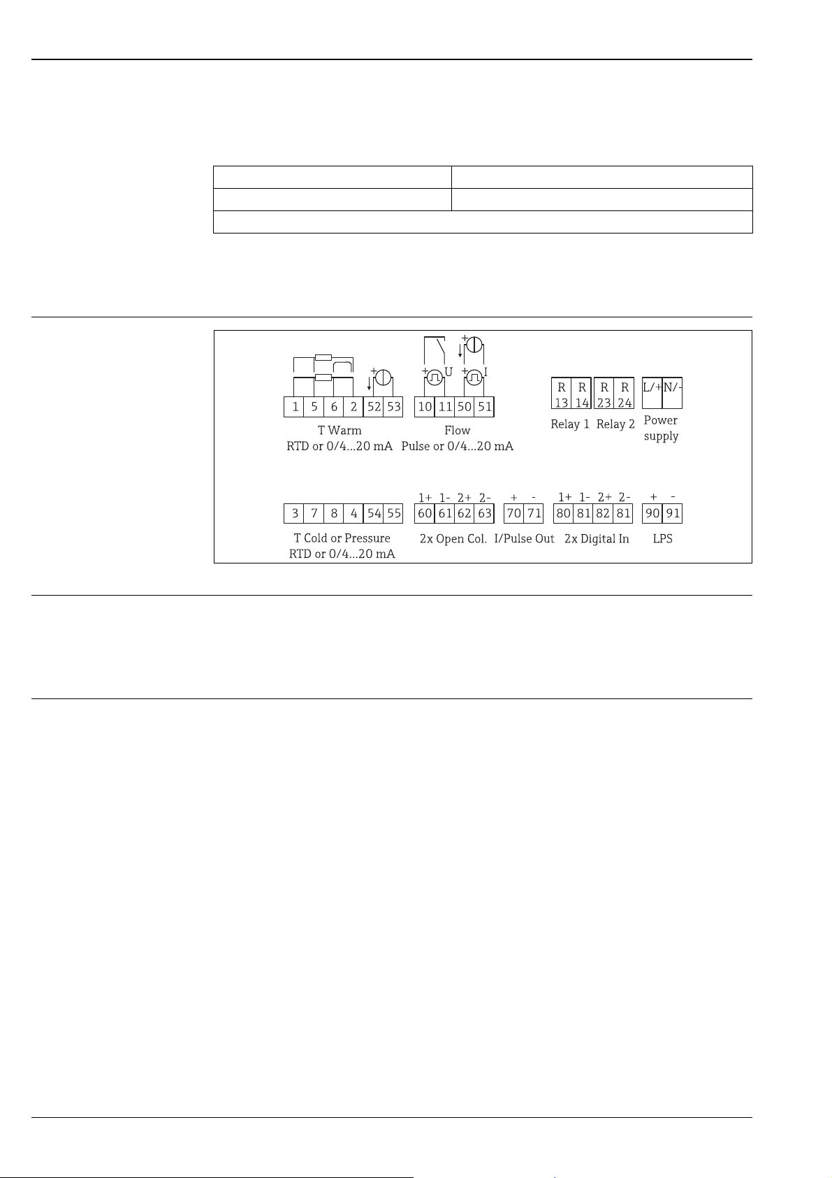
Electrical connection
The auxiliary voltage output can be used to power the transmitter or control the digital inputs. The auxiliary voltage is short-circuit proof and galvanically isolated (500 V testing voltage towards all other
inputs and outputs).
Output voltage: 24 V DC ±15% (not stabilized)
Output current: Max. 70 mA
®
signals are not affected.
HART
Terminal assignment
Terminal assignment of the EngyCal® RH33
Supply voltage • Low-voltage power unit: 100 to 230 V AC (-15% / +10%) 50/60 Hz
• Extra-low voltage power unit:
24 V DC (-50% / +75%)
24 V AC (±50%) 50/60 Hz
An overload protection unit (rated current ≤ 10 A) is required for the power cable.
Power consumption 15 VA
A0022341
10 Endress+Hauser
Page 11

EngyCal® RH33
Communication interfaces
A USB interface (with CDI protocol), and optionally Ethernet, are used to configure the device and read
out the values. ModBus and M-Bus are optionally available as communication interfaces.
None of the interfaces has a modifying effect on the device in accordance with PTB Requirement PTBA 50.1.
USB device
Connection: Type B socket
Specification: USB 2.0
Speed: Full speed (max. 12 MBit/sec)
Max. cable length: 3 m (9.8 ft.)
Ethernet TCP/IP The Ethernet interface is optional, and cannot be combined with other optional interfaces. It is galvan-
ically isolated (testing voltage: 500 V). A standard patch cable (e.g. CAT5E) can be used to connect the
Ethernet interface. A special cable gland is available for this purpose which allows users to guide preterminated cables through the housing. Via the Ethernet interface, the device can be connected to
office equipment using a hub or a switch.
Standard: 10/100 Base-T/TX (IEEE 802.3)
Socket: RJ-45
Max. cable length: 100 m (328 ft.)
Web server
When the device is connected via Ethernet, the display values can also be read out via the Internet
using a web server.
Data can be read out via the web server in HTML or XML format.
RS485
Connection 3-pin plug-in terminal
Transmission protocol RTU
Transmission rate 2400/4800/9600/19200/38400
Parity Choose from None, Even, Odd
Modbus TCP The Modbus TCP interface is optional, and cannot be ordered with other optional interfaces. It is used
to connect the device to higher-order systems to transmit all measured values and process values. The
Modbus TCP interface is physically identical to the Ethernet interface.
Modbus RTU The Modbus RTU (RS-485) interface is optional, and cannot be ordered with other optional interfaces.
It is galvanically isolated (testing voltage: 500 V) and used to connect the device to higher-order systems to transmit all measured values and process values. It is connected via a 3-pin plug-in terminal.
M-Bus The M-Bus (Meter Bus) interface is optional, and cannot be ordered with other optional interfaces. It
is galvanically isolated (testing voltage: 500 V) and used to connect the device to higher-order systems
to transmit all measured values and process values. It is connected via a 3-pin plug-in terminal.
Endress+Hauser 11
Page 12

Performance characteristics
EngyCal® RH33
Reference operating conditions
Arithmetic unit
• Power supply 230 V AC ± 10%; 50 Hz ± 0.5 Hz
• Warm-up time > 2 h
• Ambient temperature 25 °C ± 5 K (77 ± 9 °F)
• Humidity 39% ± 10% RH
Medium Variable Range
Temperature measuring range 0 to 350 °C (32 to 662 °F)
Temperature differential range ΔT 0 to 350 K (0 to 630 °F)
Measuring range approved for custody
Water
Water/glycol Glycol concentration 0-60 %
Liquids Temperature measuring range -200 to 600 °C (-328 to 1112 °F)
Measurement and calculation interval 500 ms
transfer
Accuracy 3 to 20 K (5.4 to 36 °F) < 0.7% of the measured
Accuracy acc. to EN1434/OIML75 ± (0.5 + ΔΘ min/ΔΘ) %
Temperature measuring range -40 to 350 °C (-40 to 662 °F)
Maximum temperature differential
range ΔT
Accuracy (0 - 40 % glycol) 3 to 20 K (5.4 to 36 °F) < 0.9% of the measured
Maximum temperature differential
range ΔT
Error limit for ΔTsee water
0 to 300 °C (32 to 572 °F)
ΔT: 3 to 297 K (5.4 to 534.6 °F)
value
20 to 300 K (36 to 540 °F) < 0.2% of the measured value
0 to 390 K (0 to 702 °F)
value
20 to 300 K (36 to 540 °F) < 0.4% of the measured value
0 to 390 K (0 to 702 °F)
Installation
Installation instructions Mounting location
Wall/pipe mounting, panel or top-hat rail as per IEC 60715
1)
Orientation
The orientation is only determined by the legibility of the display.
Environment
Ambient temperature range -20 to +60 °C (-4 to +140 °F)
Storage temperature -30 to +70 °C (-22 to 158 °F)
Climate class As per IEC 60 654-1 Class B2, as per EN 1434 ambient class C
1) According to UL approval panel or surface mountable only.
12 Endress+Hauser
Page 13
EngyCal® RH33
Humidity Maximum relative humidity 80 % for temperatures up to 31 °C (87.8 °F), decreasing linearly to 50 %
relative humidity at 40 °C (104 °F).
Electr. safety As per IEC 61010-1, UL61010-1 and CAN C22.2 No 1010-1.
• Protection class II
• Overvoltage category II
• Pollution degree 2
• Overload protection ≤ 10 A
• Operating altitude: up to 2000 m (6560 ft) above MSL
Degree of protection • Panel mounting: IP65 front panel, IP20 rear panel (not evaluated by UL)
• Top-hat rail: IP20
• Field housing: IP66, NEMA4x (for cable gland with double seal insert: IP65) (not evaluated by UL)
Electromagnetic compatibil-
As per EN 1434-4, EN 61326 and Namur NE21
ity
Mechanical construction
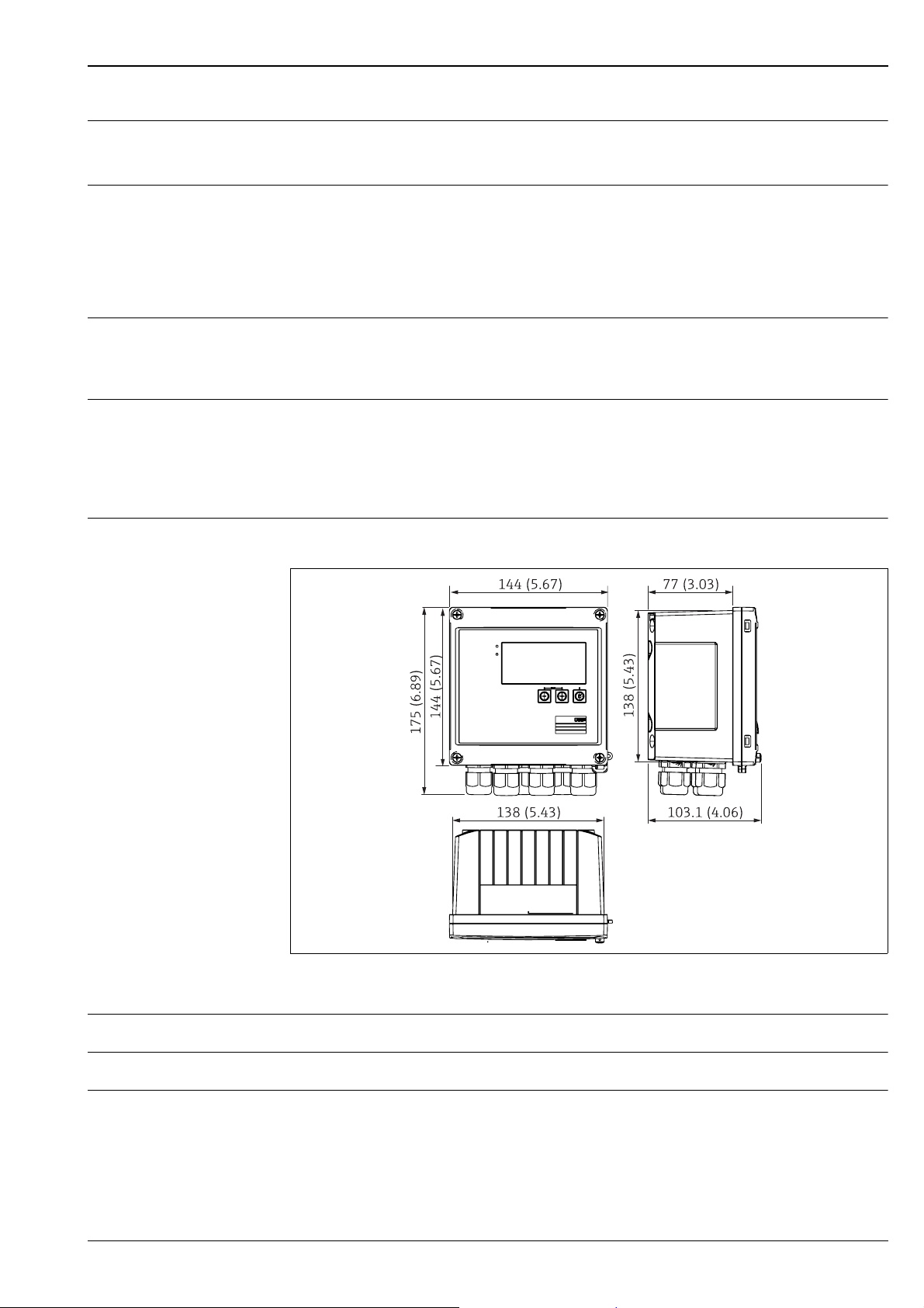
Design, dimensions EngyCal® RH33
a0013438
BTU meter housing; dimensions in mm (in)
Weight Approx. 700 g (1.5 lbs)
Material Housing: fiber-glass reinforced plastic, Valox 553
Terminals Spring terminals, 2.5 mm
2
(14 AWG); auxiliary voltage with plug-in screw terminal (AWG 30-12;
torque 0.5-0.6 Nm).
Endress+Hauser 13
Page 14
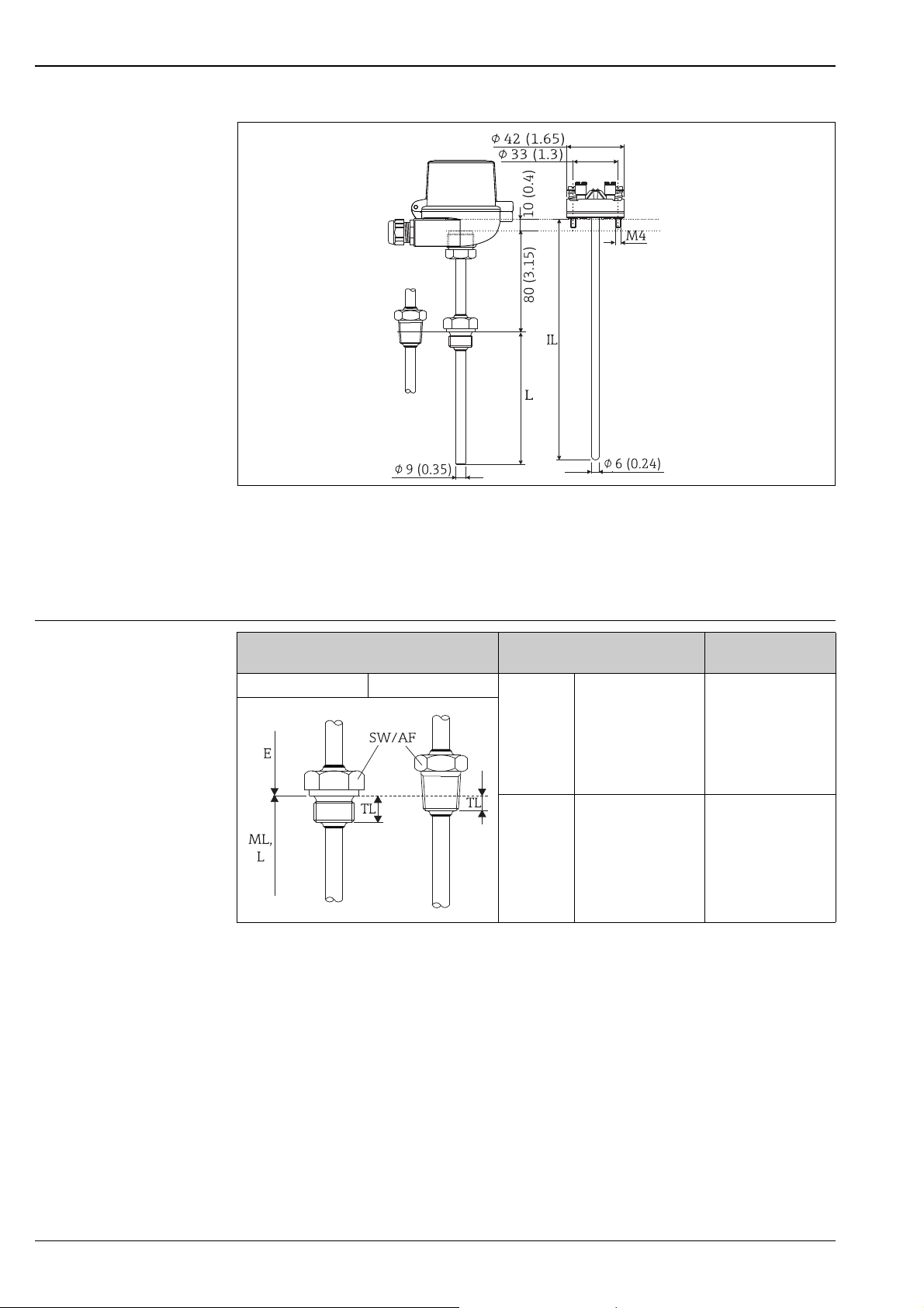
Resistance temperature detector TR10 (option)
EngyCal® RH33
a0015313
Optional resistance temperature detector TR10; dimensions in mm (dimensions in inches in brackets)
IL Insertion length
L Immersion length
Process connection of resistance temperature detector
TR10 (option)
More technical data on the resistance temperature detector TR10 can be found in the associated Technical Information, which you can download from www.de.endress.com/download.
Process connection Version Thread length TL in
mm (in)
Cylindrical Conical
G G1/2" 15 (0.6)
NPT NPT1/2" 8 (0.32)
a0008620
14 Endress+Hauser
Page 15
EngyCal® RH33
Human interface
Display elements •Display:
160 x 80 dot matrix LCD with white background, color switches to red in an alarm condition, active
display area 70 x 34 mm (2.76 x 1.34 ")
• LED status display:
Operation: 1 x green
Fault indication: 1 x red
a0013444
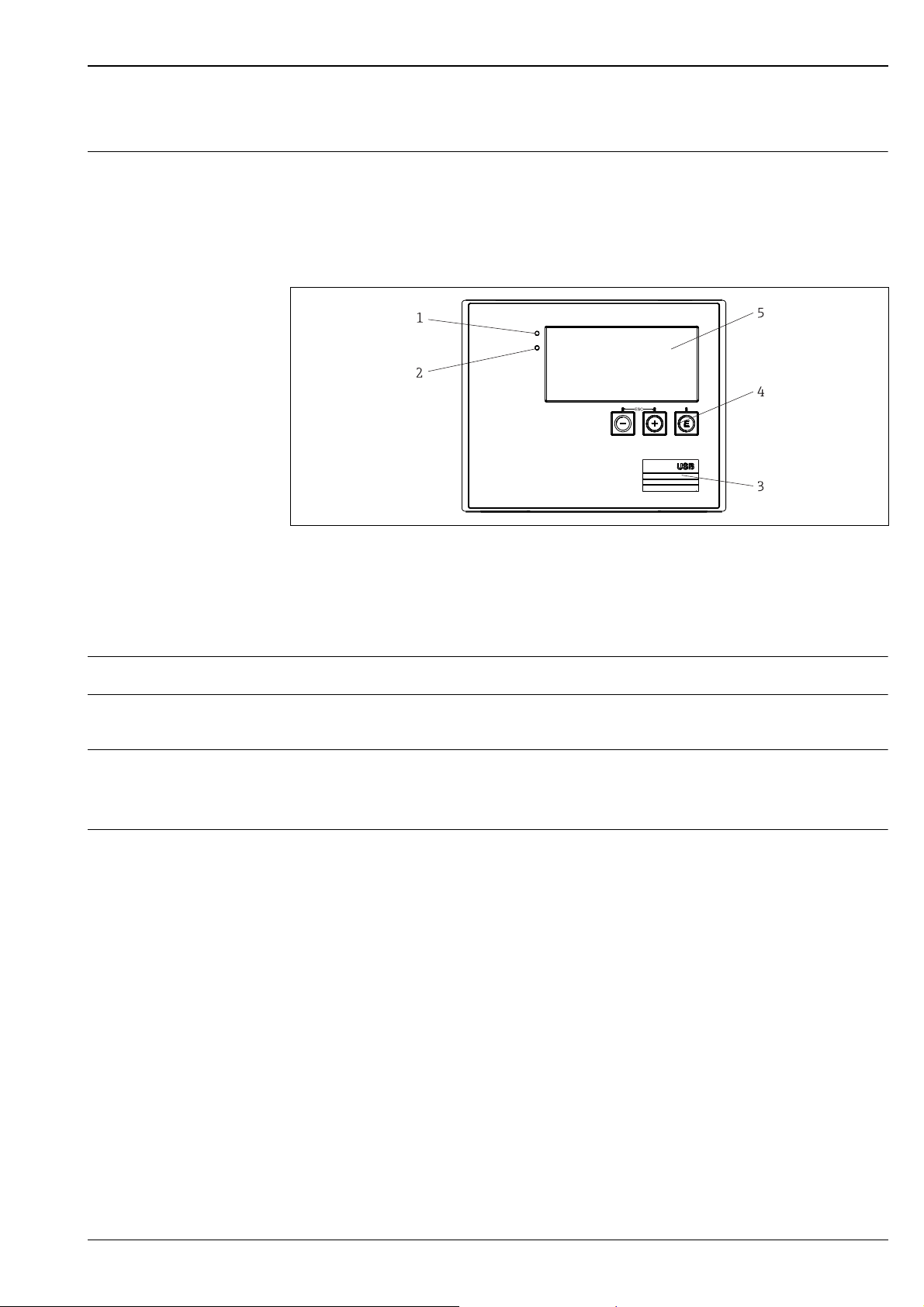
Display and operating elements of the BTU meter
1 LED green, "Operation"
2 LED red, "Fault indicator"
3 USB connection for configuration
4 Operating keys: -, +, E
5 160x80 DOT matrix display
Local operation 3 keys, "-", "+", "E".
Configuration interface USB interface, front-panel, optional Ethernet interface: configuration via PC with FieldCare Device
Setup configuration software.
Data logging Real time clock
• Drift: 15 min per year
• Power reserve: 1 week
Software • Field Data Manager software MS20: Visualization software and database for analyzing and eval-
uating the measuring data and calculated values, as well as tamper-proof data logging.
• FieldCare Device Setup: The device can be programmed using the FieldCare PC software. FieldCare
Device Setup is included in the scope of supply of the Commubox FXA291 or RXU10-G1 (see ‘Accessories’) or can be downloaded at no charge from www.products.endress.com/fieldcare.
Endress+Hauser 15
Page 16

EngyCal® RH33
Certificates and approvals
Approval for custody transfer As per MID (EN1434 water/liquids) and OIML R75
CE mark The measuring system meets the legal requirements of the EU directives. Endress+Hauser confirms
successful testing of the device by affixing to it the CE mark.
Other standards and guidelines
CSA GP • CAN/CSA-22.2 No. 61010-1, 2
UL approval • UL 61010-1, 2nd Edition
• IEC 60529:
Degrees of protection provided by enclosures (IP code)
• IEC 61010-1: 2001 cor 2003
Safety requirements for electrical equipment for measurement, control and laboratory use
• IEC 61326 series:
Electromagnetic compatibility (EMC requirements)
• NAMUR NE21, NE43
Association for Standards for Control and Regulation in the Chemical Industry
•IAWPS-IF 97
Internationally applicable and recognized calculation standard (since 1997) for steam and water.
Issued by the International Association for the Properties of Water and Steam (IAPWS).
•OIML R75
International construction and testing regulation for water energy managers by the Organisation
Internationale de Métrologie Légale.
• EN 1434
• EN ISO 5167
Measurement of fluid flow by means of pressure differential devices
nd
Edition
16 Endress+Hauser
Page 17

EngyCal® RH33
Ordering information
Detailed ordering information is available from the following sources:
• In the Product Configurator on the Endress+Hauser website: www.endress.com → Select country →
Instruments → Select device → Product page function: Configure this product
• From your Endress+Hauser Sales Center: www.endress.com/worldwide
Product Configurator - the tool for individual product configuration
• Up-to-the-minute configuration data
• Depending on the device: Direct input of information specific to measuring point, such as measuring
range or operating language
• Automatic verification of exclusion criteria
• Automatic creation of the order code and its breakdown in PDF or Excel output format
• Ability to order directly in the Endress+Hauser Online Shop
Accessories
Various accessories are available for the device, and these can be ordered with the device or at a later
stage from Endress+Hauser. Detailed information on the order code in question is available from your
local Endress+Hauser Sales Center or on the product page of the Endress+Hauser website:
www.endress.com
Device-specific accessories •Pipe mounting set
• DIN rail mounting set
• Panel mounting set
• Wall mounting set
• USB cable and FieldCare Device Setup calibration software incl. DTM library
– RXU10-G1
– FXA291
• Visualization software and Field Data Manager MS20, SQL-based database software
System components Overvoltage protection for sensors and devices:
• HAW569 surge arrester to screw into field housing, M20
• HAW562 surge arrester limiting high voltages on signal cables and components
Documentation
• Operating Instructions for 'EngyCal® RH33 BTU Meter' (BA00290K/09)
• Technical Information for 'Surge Arrester HAW562' (TI01012K/09)
• Technical Information for 'Surge Arrester HAW569' (TI01013K/09)
• Brochure 'System Components and Data Managers - Solutions for a Complete Measuring Point'
(FA00016K/09)
Endress+Hauser 17
Page 18

www.addresses.endress.com
 Loading...