

Page 1
Technical Information
Omnigrad S TMT162R
RTD assembly
®
with HART
or PROFIBUS
-, FOUNDATION Fieldbus™-
®
PA field transmitter
Application
• Chemical/pharmaceutical industry
• Petrochemical industry
• Energy industry
• Paper industry
• General industrial applications
The TMT162R RTD assembly comprises a measuring
insert (Pt100) and an electronic field transmitter with
®
, FOUNDATION Fieldbus™ or PROFIBUS® PA
HART
protocol.
Features and benefits
• Dual compartment housing
• Backlit display with large measured value, bargraph
and fault condition indication
• Galvanic isolation 2 kV (sensor input to the output)
• Wide range of threaded thermowell connections available as standard, additional connections available on
request
• Replaceable measuring insert comprising a mineralinsulated tube (SS 316L/1.4404)
• Pt100 measuring resistor with accuracy class A
(IEC 60751) or 1/3 DIN B to maximize the measuring
range: -200 to +600 °C (-328 to 1112 °F)
• Aluminum or stainless steel housing,
degree of protection IP67, NEMA 4x
• Approvals for hazardous areas:
Flameproof enclosure (Ex d)
Intrinsic safety (Ex ia)
Non-sparking (Ex nA)
• Optional: 2 x Pt100 (3-wire), e.g. for redundant applications or differential measurement
• Optional factory calibration
TI266t/02/en
71093902
Page 2
TMT162R
Function and system design
Measuring principle The resistance temperature detector (RTD) element has an electrical resistance with a value of 100 Ω at 0 °C
(32 °F). It is commonly known as Pt100 and complies with IEC 60751. This resistance value increases at higher
temperatures according to the characteristics of the sensor material (platinum). These kinds of sensors are
called Positive Temperature Coefficient elements (PTC). The coefficient is fixed with α = 0.00385 °C
lated between 0 and 100 °C (32 and 212 °F), according to ITS90 (International Temperature Scale).
Measuring system
-1
, calcu-
TMT162R
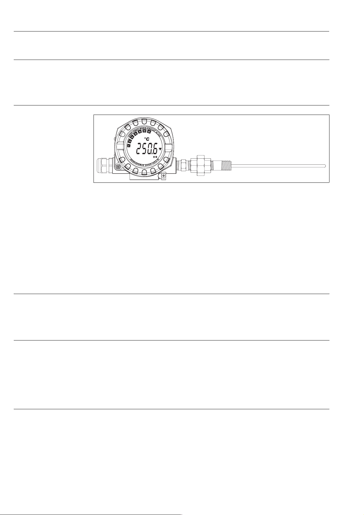
The TMT162R RTD assembly comprises a measuring insert with a Pt100 sensor element and the iTEMP®
TMT162 field transmitter which can be configured using the HART®, FOUNDATION Fieldbus™ or PROFIBUS® PA protocol. A thermowell can be ordered separately.
The Pt100 sensor element complies with IEC 60751 and withstands loads that typically occur in the most common industrial processes. The wire wound (WW) version of the sensor is supplied and is located in the tip of
the measuring insert. The measuring insert is a replaceable unit and is installed in a thermowell.
A spring system presses the measuring insert against the base of the thermowell to improve the transmission
of heat.
The transmitter housing is made of die-cast aluminum or stainless steel. It can be purchased with or without
an LC display. The minimum degree of protection, IP65, is achieved by sealing glands at the cable entry and
the thermometer connection. Depending on the customer's requirements, customers can choose from thermowells constructed from welded tubes and thermowells made of drilled barstock material. The thermowells
are available in various shapes and sizes and with a wide range of process connections (thread, flange or weldon connections, see page 12).
Measurement range -200... 600 °C (-328...1112 °F) according to IEC 60751
Performance characteristics
Operating conditions Ambient temperature limits
• Without display: -40 to +85 °C (-40 to 185 °F)
• With display: -40 to +80 °C (-40 to 176 °F)
TMT162R_G_dd_07_xx_04
For use in Ex area, see Ex certificate.
!
Storage temperature • Without display: -40 to +100 °C (-40 to 212 °F)
2 Endress+Hauser
Note!
At temperatures < -20 °C (-4 °F), the display may react slowly. Readability of the display cannot be guaranteed
at temperatures < -30 °C (-22 °F).
• With display: -40 to +80 °C (-40 to 176 °F)
Page 3
Process pressure/flow velocity
The load limits of the thermometer depend on the thermowell used and are listed in the technical information
specific to the individual thermowells (see page 12). Factors that affect the load limits include the process pressure, flow velocity, density of the medium, temperature, immersion depth, length of the thermowell in the
flowing medium etc. In critical situations, a load capacity calculation for the thermowell can be ordered from
Endress+Hauser.
Shock and vibration resistance
3 g (max. value)/ 10 to 500 Hz as per IEC 60 068-2-6
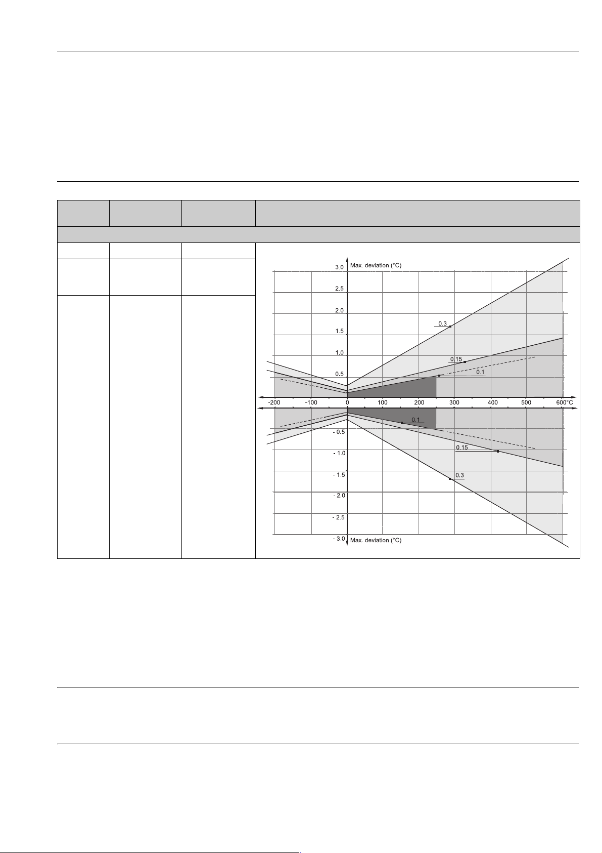
Accuracy RTD corresponding to IEC 60751
Class max. Tolerances
RTD max. error type WW - range: -200 to +600 °C
W0.15 (Cl. A) 0.15 ± 0.002 · |t|
W0.1 (Cl. AA
former
1/3 Cl. B)
W0.3 (Cl. B) 0.3 ± 0.005 · |t|
(°C)
0.10 ± 0.0017 · |t|
Temperature range Characteristics
1)
-200 °C to +600 °C
1)
0 °C to +250 °C
1)
-200 °C to +600 °C
TMT162R
a0008588-en
1. |t| = absolute value °C
Note!
!
For measurement errors in °F, calculate using equations above in °C, then multiply the outcome by 1.8.
The 4-wire technology is the optimum connection method for RTDs. Here, the measurement is effected by
means of a measuring and supply circuit, making it completely independent of the properties of the cable.
When using Pt100 sensors, Class A or 1/3DIN B, it is always presumed that 4-wire measurement is carried
out in accordance with IEC 60751 since the best measuring results can be obtained in practice in this way.
Response time Tests in water at 0.4 m/s (1.3 ft/s), according to IEC 60751; 10 K temperature step changes; response time
for the assembly without thermowell and transmitter:
: 3.5 s
•t
50
•t
: 8 s
90
Insulation resistance Insulation resistance ≥100 MΩ at ambient temperature.
Insulation resistance between each terminal and the sheath is tested with a voltage of 250 V DC.
Endress+Hauser 3
Page 4

TMT162R
Transmitter specifications
Measurement accuracy 0.1 °C (0.18 °F)
Sensor current ≤ 0.3 mA
Galvanic isolation
(input/output)
1. % relates to the set span. Accuracy = digital + D/A accuracy, for 4 to 20 mA output
Self heating Negligibly small
Material
Housing Nameplate Neck, insert
Die-cast aluminum housing AlSi10Mg
with powder coating on polyester basis
Stainless steel 1.4435 (AISI 316L) 1.4301 (AISI 304)
TMT162 FF/PA TMT162 HART
Accuracy
Digital D/A
0.1 °C (0.18 °F) 0.02%
U = 2 kV AC
Aluminum AlMgl, anodized in black Stainless steel 1.4404 (AISI 316L)
®
1
Installation conditions
Orientation No restrictions.
Electromagnetic compatibility (EMC)
CE Electromagnetic Compatibility Compliance
EMC meets all relevant requirements listed under EN 61326 Series and NAMUR NE21. Details as per declaration of conformity.
This recommendation is a uniform and practical way of determining whether the devices used in laboratories
and process control are immune to interference with an objective to increase its functional safety.
ESD (Electrostatic discharge) IEC 61000-4-2 6 kV cont., 8 kV air
Electromagnetic fields IEC 61000-4-3 0.08 to 2 GHz
Burst (fast transient) IEC 61000-4-4 1 kV (2 kV for HART)
surge IEC 61000-4-5 1 kV asym. (0.5 kV sym. for HART)
Conducted RF IEC 61000-4-6 0.01 to 80 MHz 10 V
(0.08 to 4 GHz for FF)
0.08 to 2 GHz for HART
2 to 2.7 GHz
10 V/m
10 V/m
30 V/m
1V/m
4 Endress+Hauser
Page 5
Installation instructions
a
a
a
a
a
a
a
a
a
a
a
a
a
a
a
a
a
a
a
a
a
a
a
a
a
a
a
a
a
a
a
a
a
a
a
a
a
a
a
a
a
a
a
a
a
a
a
a
a
a
a
a
a
a
a
a
a
a
a
a
a
a
a
a
a
a
a
a
a
a
a
a
a
a
a
a
a
a
a
a
a
a
a
a
a
a
a
a
a
a
a
a
a
a
a
a
a
a
a
a
a
a
a
a
a
a
a
a
a
a
a
a
a
a
a
a
a
a
a
a
a
a
a
a
a
a
a
a
a
a
a
a
a
a
a
a
a
a
a
a
a
a
a
a
a
a
a
a
a
a
a
a
a
a
a
a
a
a
a
a
a
a
a
a
a
a
a
a
a
a
a
a
a
a
a
a
a
a
a
a
a
a
a
a
a
a
a
a
a
a
a
a
a
a
a
a
a
a
a
a
a
a
a
a
a
a
a
a
a
a
a
a
a
a
a
a
a
a
a
a
a
a
a
a
a
a
a
a
a
a
a
a
a
a
a
a
a
a
a
a
a
a
a
a
a
a
a
a
a
a
a
a
a
a
a
a
a
a
a
a
a
a
a
a
a
a
a
a
a
a
a
a
a
a
a
a
a
a
a
a
a
a
a
a
a
a
a
a
a
a
a
a
a
a
a
a
a
a
a
a
a
a
a
a
a
a
a
a
a
a
a
a
a
a
a
a
a
a
a
a
a
a
a
a
a
a
a
a
a
a
a
a
TMT162R
!
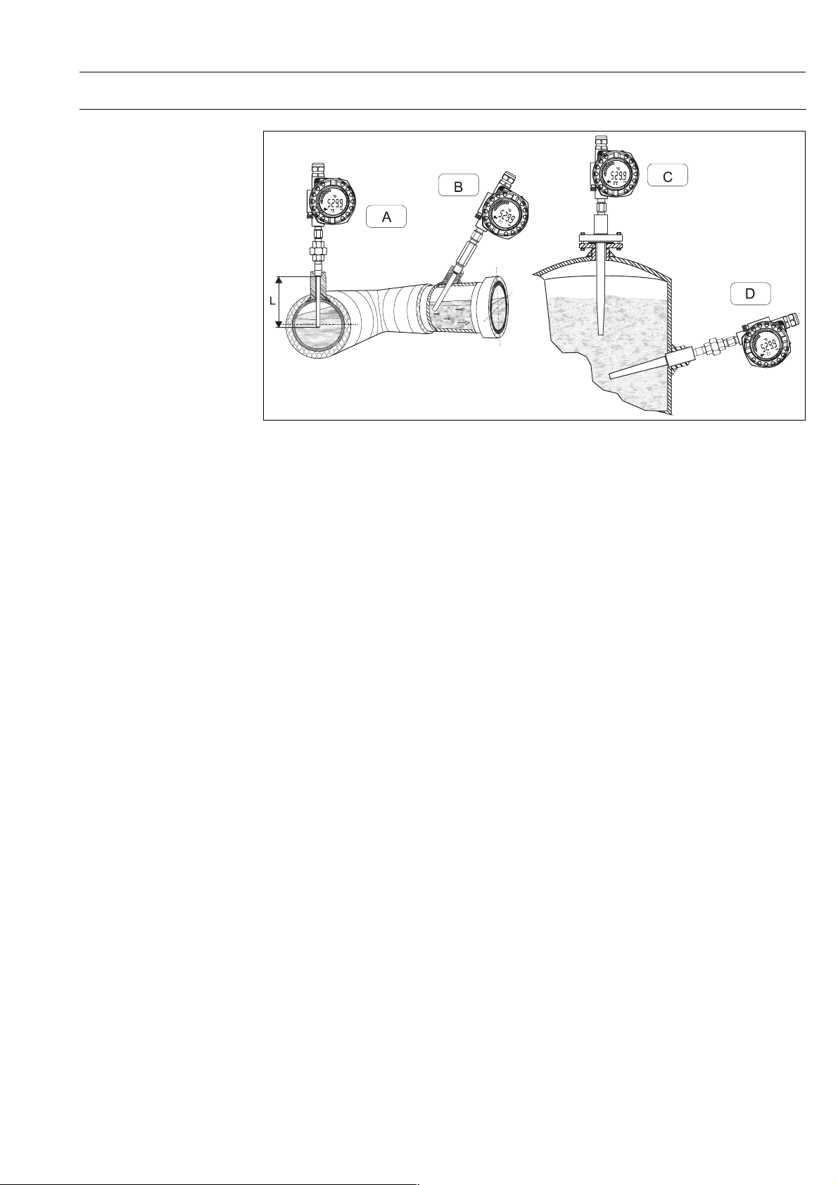
Installation examples
T09-TMT162RC-11-xx-xx-xx-003
A: In pipes with a small cross section the sensor tip should reach or extend slightly past the center line of the pipe (= L).
B, D: Tilted installation
C: Flanged installation
The immersion length of the thermometer influences the accuracy. If the immersion length is too small then
errors in the measurement are caused by heat conduction via the process connection and the pipe wall. If
installing into a pipe then the immersion length must be half of the pipe diameter, ideally.
• Installation possibilities: Pipes, tanks or other plant components
• Minimum immersion length = 80 to 100 mm (3.15 to 3.94 in)
The immersion length must be at least 8 times the protection tube diameter. Example: Protection tube diameter 12 mm (0.47 in) x 8 = 96 mm (3.8 in). Recommended standard immersion length according to DIN
43772: 120 mm (4.72 in)
• ATEX certification: Always take note of the installation regulations!
Note!
When operating in small nominal bore pipes it must be guaranteed that the protection tube tip is long enough
to extend past the pipe center line (see Pos. A and B). A further solution could be an angled (tilted) installation
(see Pos. C and D). When determining the immersion length all thermometer parameters and the process to
be measured must be taken into account (e.g. flow velocity, process pressure).
In the case of pipes in which the direction of flow changes, extreme caution should be exercised when selecting
the measuring point since these flows can cause the measured value to fluctuate. With regard to corrosion, the
choice of material for the thermowell is particularly important.
If the thermometer is to be disassembled into its individual component parts, the specified tightening torques
have to be observed when subsequently reassembling the thermometer in order to comply with the IP protection class of the coupling between the field transmitter and thermowell.
Endress+Hauser 5
Page 6
TMT162R
System components
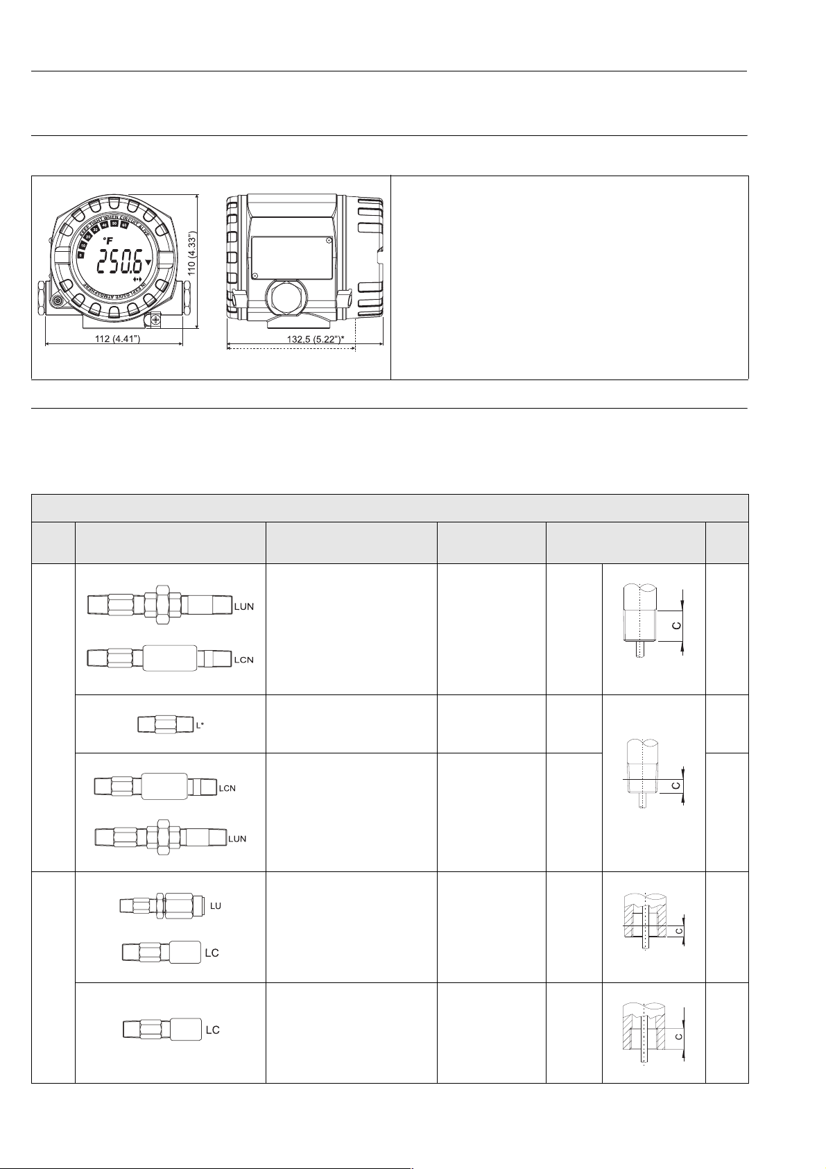
Field transmitter The field transmitter offers high reliability particularly in harsh industrial environments due to the dual com-
partment housing and fully potted electronics.
Temperature field transmitter iTEMP® TMT162
* Dimensions without display = 112 mm (4.41“)
T09-TMT162ZZ-06-00-xx-xx-001
Neck tube A neck tube is integrated between the thermowell and the field transmitter to prevent the field transmitter from
overheating as a result of the process temperature. This neck tube is made up of one or more different pipe
fittings (N, L = nipples and C, U = coupling, unions). The material of the neck tube is SS 316L/1.4404 as standard.
The neck tube versions and standard lengths (N) can be selected as follows:
.
Neck tube versions
• Material: die-cast aluminum housing AlSi10Mg with powder coating on polyester base or stainless steel 1.4435 (AISI 316L)
• Separate electronics compartment and connection compartment
• Display pluggable in 90° stages
• Cable entry: 2x ½" NPT, M20x1.5
• Thermowell connection (min. IP 65): M24x1.5, ½" NPT, ¾" NPT, G½"
• Degree of protection IP 67 (NEMA 4X)
• Blue backlit display with large measured value, bargraph and fault condition
indication
• Gold-plated terminals prevent corrosion and additional measured errors
For detailed information, see Technical Information iTEMP
®
TMT162
(see page 12).
Type Neck tube type Neck tube length N Thermowell con-
nection thread
– 156 mm (6.14 in)
(type LUN, field transmitter can
be aligned)
nckLUN_g_gd_15_xx_01
– 148 mm (5.83 in)
G ½”
(type LCN, field transmitter cannot be aligned)
nckLCN_g_gd_15_xx_01
– 52 mm (2 in)
*only ½” NPT
(type L, field transmitter cannot
External thread
nckLxx_g_gd_15_01
be aligned)
– 148 mm (5.83 in)
(type LCN, field transmitter can-
nckLUN_g_gd_15_xx_01
not be aligned)
– 156 mm (6.14 in)
½“ NPT,
¾” NPT
(type LUN, field transmitter can
nckLCN_g_gd_15_xx_01
be aligned)
– 104 mm (4.1 in)
(type LU, field transmitter can
be aligned)
nckLUx_g_gd_15_xx_01
½” NPT
– 96 mm (3.8 in)
(type LC, field transmitter can-
nckLCx_g_gd_15_xx_01
not be aligned)
Thread length C Digit
15 mm
(0.6 in)
ConGAS_G_dd_09_xx_01
8 mm
(0.3 in)
8.5 mm
(0.33 in)
ConNPT_G_dd_09_xx_01
8 mm
(0.3 in)
ConNPT_G_dd_09_xx_02
D
N
P
U
Internal thread
nckLCx_g_gd_15_xx_01
– 96 mm (3.8 in)
(type LC, field transmitter cannot be aligned)
M24x1.5
16 mm
(0.63 in)
5
ConM24_g_dd_09_xx_01
6 Endress+Hauser
Page 7
TMT162R
In addition to the standard versions listed, neck tubes with specific lengths can be ordered as part of the product
structure for the measuring insert.
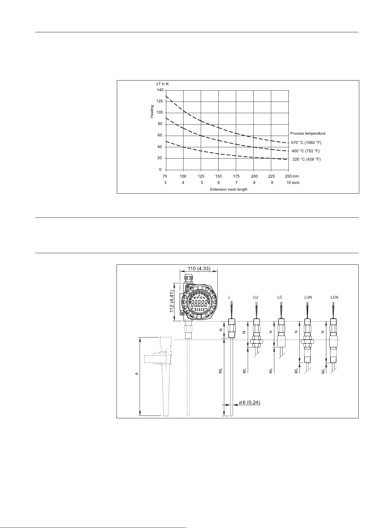
As illustrated in the following figure, the neck tube length may influence the temperature in the field transmitter. It is necessary that this temperature is kept within the limit values defined in the chapter "Operating conditions".
Heating of the field transmitter consequent to the process temperature.
Temperature in the field transmitter = ambient temperature + ΔT
a0010513-en
Thermowell The assembly is designed for installation in an existing thermowell, or a thermowell that has to be ordered sep-
arately. For this purpose, the neck tube connection to the thermowell is available in various sizes.
To make selection easier, please use the table with the insertion lengths of the measuring insert (ML) which is
described in the next section.
Measuring insert
Omnigrad S TMT162R, dimensions in mm (inch)
T09-TMT162RC-04-xx-xx-xx-000
The insertion length (ML) of the measuring insert can be selected anywhere in the range between 50 and 990
mm (1.97 and 39 in). Insertion lengths over 990 mm (39 in) are available on request.
Endress+Hauser 7
Page 8

TMT162R
The insertion length (ML) must be selected depending on the total length of the thermowell (A) and the type
of thermowell used (applies to standard thermowell base sizes). This also applies when ordering the measuring
insert as a spare part. Please refer to the table below for exact details.
Thermowell
type
TW10* ML = A - 8 mm (0.31 in) TA535 ML = A - 8 mm (0.31 in) TA560 ML = A - 11 mm (0.43 in)
TW11* ML = A - 8 mm (0.31 in) TA540 ML = A - 10 mm (0.4 in) TA566 ML = A - 11 mm (0.43 in)
TW12* ML = A - 8 mm (0.31 in) TA541* ML = A - 10 mm (0.4 in) TA570 ML = A - 11 mm (0.43 in)
TW13* ML = A - 8 mm (0.31 in) TA550 ML = A - 11 mm (0.4 in) TA571 ML = A - 11 mm (0.43 in)
TW10** ML = A - 15 mm (0.6 in) TA555 ML = A - 10 mm (0.4 in) TA572 ML = A - 11 mm (0.43 in)
TW11** ML = A - 15 mm (0.6 in) TA556 ML = A - 10 mm (0.4 in) TA575 ML = A - 11 mm (0.43 in)
TW12** ML = A - 15 mm (0.6 in) TA557 ML = A - 10 mm (0.4 in) TA576 ML = A - 10 mm (0.4 in)
TW13** ML = A - 15 mm (0.6 in) TA562 ML = A - 11 mm (0.43 in)
TW15** ML = A - 12 mm (0.47 in) TA565 ML = A - 11 mm (0.43 in)
ML in mm (inch) Thermowell
type
ML in mm (inch) Thermow-
If the thermowell selected also contains a neck tube (e.g. TW15), the total length A of the thermowell is the
sum of the length of the thermowell L plus the length of the neck tube E (A = L + E).
Caution!
"
* TMT162R with NPT threaded connection to the thermowell
** TMT162R with metric (M24x1.5) connection to the thermowell
Weight From 1.5 to 5 kg (3.3 to 12.1 lbs) for standard options (aluminum housing).
ell type
ML in mm (inch)
Electronics
The iTEMP® temperature field transmitter TMT162 is a two-wire transmitter with analog output or fieldbus
protocol, two (optional) measuring inputs for resistance thermometers in 2-wire, 3-wire or 4-wire connection
(for one resistance measuring input). The LC display shows the current measured value digitally and as a bar
graph with an indicator for alarms.
Corrosion detection
Corrosion of the sensor connections can lead to corruption of the measured value. The field transmitter offers
the option of detecting corrosion on thermocouples and resistance thermometers with a 4-wire connection
before measured value corruption occurs.
If the conductor resistance exceeds plausible limits, the transmitter shows a status message on the display and
forwards the corresponding message to the higher-order system via HART, FOUNDATION Fieldbus™ or
PROFIBUS
Optional 2-channel functions
These functions increase the reliability and availability of the process values:
• Sensor backup switches to redundant sensor if primary sensor fails
• Temperature dependent switching between sensors, which have advantages in different ranges
• Drift alert or alarm if sensor 1 and 2 deviate from one another
®
PA protocol.
8 Endress+Hauser
Page 9
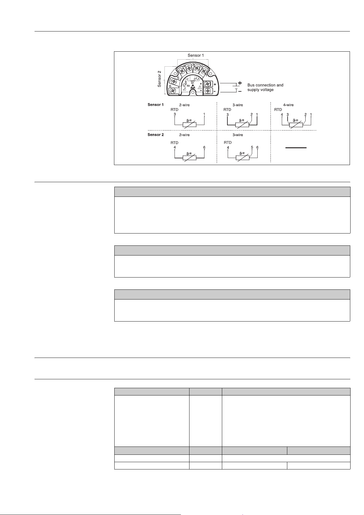
Wiring diagram
TMT162R
Supply voltage
Electrical connection
®
HART
TMT162Rx-04-xx-xx-en-000
Ub = 11 to 40 V (8 to 40 V without display), reverse polarity protection
Note!
!
(according to IEC 61010-1, CSA 1010.1-92)
The TMT162 must be powered by a 11 to 40 VDC power supply with a limited power according to NEC Class 02 (low
voltage, low current) limited to 8 A and 150 VA in case of a short circuit.
FOUNDATION Fieldbus™
U
= 9 to 32 V, reverse polarity protection,
b
max. voltage U
= 35 V
b
According to IEC 60079-27, FISCO/FNICO
PROFIBUS® PA
Ub= 9 to 32 V, reverse polarity protection,
max. voltage U
= 35 V
b
According to IEC 60079-27, FISCO/FNICO
Certificates and approvals
CE-Mark The device meets the legal requirements of the EC directives. Endress+Hauser confirms that the device has
been successfully tested by applying the CE mark.
Hazardous area approvals
ATEX II1G EEx ia IIC T6/T5/T4 HART
Power supply (+ and - terminals) U
ATEX II3G EEx nA II T6/T5/T4
Power supply (+ and - terminals) U ≤ 40 V DC U ≤ 32 V DC
Output I = 4 to 20 mA Curr. consumption I ≤ 12 mA Curr. consumption I ≤ 11 mA
Endress+Hauser 9
®
≤ 30 V DC
i
I
≤ 300 mA
i
P
≤ 1000 mW
i
C
≤ 5 nF
i
L
≈ 0
i
®
HART
FOUNDATION Fieldbus™/PROFIBUS® PA
≤ 17.5 V DC or:
U
i
I
≤ 500 mA
i
P
≤ 5.5 W
i
C
≤ 5 nF
i
L
= 10 μH
i
≤ 24 V DC
U
i
I
≤ 250 mA
i
P
≤ 1.2 W
i
Suitable for connecting to a fieldbus system in accordance with
the FISCO/FNICO model (valid for FOUNDATION Fieldbus™
protocol)
FOUNDATION Fieldbus™
PROFIBUS® PA
Page 10

TMT162R
ATEX II2D EEx tD A21 IP67 T110°C
ATEX II2G EEx d IIC T6/T5/T4
Power supply (+ and - terminals) U ≤ 40 V DC
Temperature range for Ex d
(electronics)
T6
T5
T4
®
HART
P ≤ 3 W
Ta = -40 °C to +55 °C
Ta = -40 °C to +70 °C
Ta = -40 °C to +80 °C
FOUNDATION Fieldbus™
PROFIBUS
®
PA
U ≤ 35 V DC
P ≤ 3 W
Temperature range for dust (electronics) Ta = -40 °C to +80 °C
For further details on the available Ex versions (ATEX, CSA, FM, etc.), please contact your nearest
Endress+Hauser sales organization. All relevant data for hazardous areas can be found in separate Ex
documentation. If required, please request copies.
PED approval The thermometer complies with paragraph 3.3 of the Pressure Equipment Directive (97/23/CE) and is not
marked separately.
Test report and calibration With regards to the tests and calibration, the "Inspection Report" consists of a compliance declaration for the
essential points of the standard IEC 60751.
The "Factory calibration" is carried out in an EA (European Accreditation) authorized laboratory of
Endress+Hauser according to an internal procedure. A calibration may be requested separately according to an
EA accredited procedure (SIT calibration). Calibration is carried out on the thermometer insert.
Other standards and guidelines
• IEC 60529: Degree of protection by housing (IP-Code)
• IEC 61010-1: Safety requirements for electrical measurement, control and laboratory instrumentation.
• EN 61326-series: Electrical equipment for measurement, control and laboratory use - EMC requirements.
• NAMUR: User association of automation technology in process industries (www.namur.de)
• NEMA: Standardization association for the electrical industry in North America.
Ordering information
Product structure
TMT162R Housing material; Approval
A Alu; housing, general purpose
B Alu; ATEX II1G EEx ia IIC T4/T5/T6
E Alu; ATEX II 2GD EEx d IIC T6
H Alu; ATEX EEx d, EEx ia
L Alu; ATEX II 3G EEx nA IIC T4/T5/T6
M Alu; ATEX II 1/2GD EEx d IIC T6
P 316L; ATEX II 1G EEx ia IIC T4/T5/T6
Q 316L; ATEX II 2GD EEx d IIC T6
R 316L; ATEX II 1/2GD EEx d IIC T6
T Alu; ATEX II 1/2GD EEx ia IIC T4/T5/T6
Cable connection; Display
A M20x1.5; w/o display, plug 7/8" FF
B M20x1.5; + display, plug 7/8" FF
C ½" NPT; w/o display, plug 7/8" FF
D ½" NPT; + display, plug 7/8" FF
E G½“; w/o display
F G½“; + display
1 M20x1.5; w/o display
2 M20x1.5; + display
3 ½” NPT; w/o display
4 ½” NPT; + display
5 M20x1.5; w/o display, plug M12 PA
6 M20x1.5; + display, plug M12 PA
7 ½" NPT; w/o display, plug M12 PA
8 ½" NPT; + display, plug M12 PA
Configuration; Communication
B Pt100; HART
E Pt100; PROFIBUS PA
F Pt100; FOUNDATION Fieldbus
Y Special version, to be specified
10 Endress+Hauser
Page 11
TMT162R
Neck length N; Type
1 52 mm; nipple type L
2 104 mm; nipple + union type LU
3 96 mm; nipple + union type LC
4 156 mm; nipple + union + nipple type LUN
5 148 mm; nipple + union + nipple type LCN
9 ... mm, as specified
Thermowell type
0 not needed
1 Bar stock, to order separately
2 Pipe, to order separately
Thermowell connection
D Thread G½"
N Thread ½" NPT-M
P Thread ¾" NPT-M
R Thread R ½", JIS B 0203
S Thread R ¾", JIS B 0203
U Thread M24x1.5-F
5 Thread ½" NPT-F
9 Special version, to be specified
Insert diameter; Material
3 6 mm; 316L
RTD; Wire; Measurement range; Class: validity
1 1xPt100 WW; 3; -200/600 °C; A: -200/600 °C
2 1xPt100 WW; 4; -200/600 °C; A: -200/600 °C
3 1xPt100 WW; 3; -200/600 °C; 1/3B: 0/250 °C
4 1xPt100 WW; 4; -200/600 °C; 1/3B: 0/250 °C
5 2xPt100 WW; 3; -200/600 °C; A: -200/600 °C
6 2xPt100 WW; 3; -200/600 °C; 1/3B: 0/250 °C
9 Special version, to be specified
Insertion length ML
X ... mm
Y ... mm, as specified
Factory test
A 0, 100 °C, Pt100-Signal
B 0, 100 °C, Pt100-Signal, 4-20mA/loop
C 0, 100 °C, Pt100-Signal, 2 Sensors
E 0, 100, 150 °C, Pt100-Signal
F 0, 100, 150 °C, Pt100-Signal, 4-20mA/loop
G 0, 100, 150 °C, Pt100-Signal, 2 Sensors
0 not needed
TMT162R-
⇐ Order code, complete
This ordering information can give an overview about the available order options. The Endress+Hauser sales
organization can provide detailed ordering information and information on the order code.
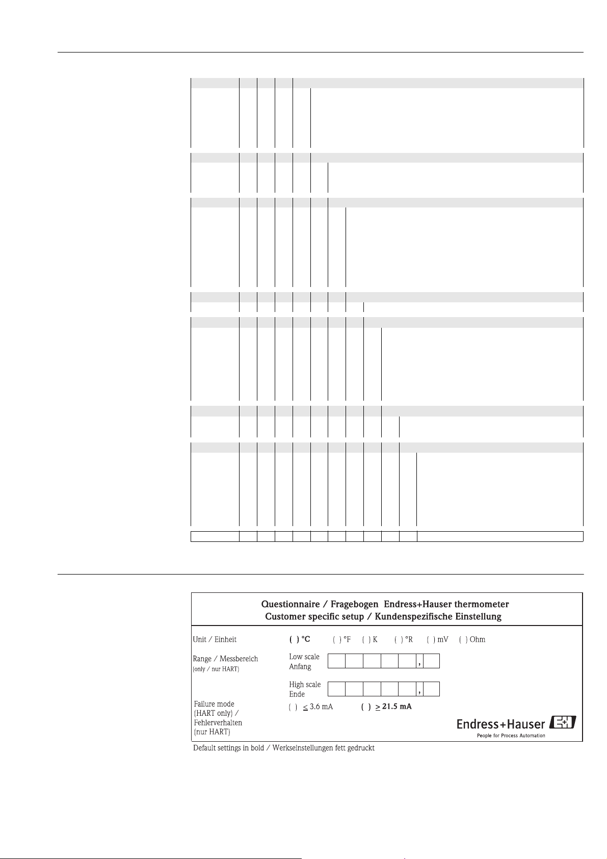
Questionnaire
A0011423
Endress+Hauser 11
Page 12
TMT162R
Documentation
Technical information:
• RTD thermometer Omnigrad TST - General information (TI088T/02)
• Temperature field transmitter iTEMP
• Measuring insert Pt100 - Omniset TET300 (TI227T/02/en)
Fitting thermowells:
• TW10 (TI261T/02)
• TW11 (TI262T/02)
• TW12 (TI263T/02)
• TW13 (TI264T/02)
• TW15 (TI265T/02)
• TA540 (TI166T/02)
Operating instructions temperature field transmitter iTEMP® TMT162:
•HART®-protocol (BA132R/09/)
• FOUNDATION Fieldbus™-protocol (BA224R/09/)
• PROFIBUS® PA-protocol (BA275R/09/)
Hazardous area supplementary documentation:
• ATEX II 1G (XA005T/02/a3)
• ATEX II 1/2G or 2G, ATEX II 1/2D or 2D (XA006T/02/a3)
®
TMT162 (TI086R/09/en)
• TA550 (TI153T/02)
• TA555 (TI154T/02)
• TA557 (TI156T/02)
• TA560 (TI159T/02)
• TA565 (TI160T/02)
• TA576 (TI163T/02)
Instruments International
Endress+Hauser
Instruments International AG
Kaegenstrasse 2
4153 Reinach
Switzerland
Tel. +41 61 715 81 00
Fax +41 61 715 25 00
www.endress.com
[email protected]
TI266T/02/en/04.09
71093902
FM+SGML 6.0
 Loading...