

Page 1
Technical Information
71105563
Omnigrad S -TC66
Thermocouple thermometer EEx-d certified, replaceable insert,
thermowell from bar stock, process connection: threaded or flanged
PCP (4...20 mA), HART® or PROFIBUS-PA® electronics
Range of uses
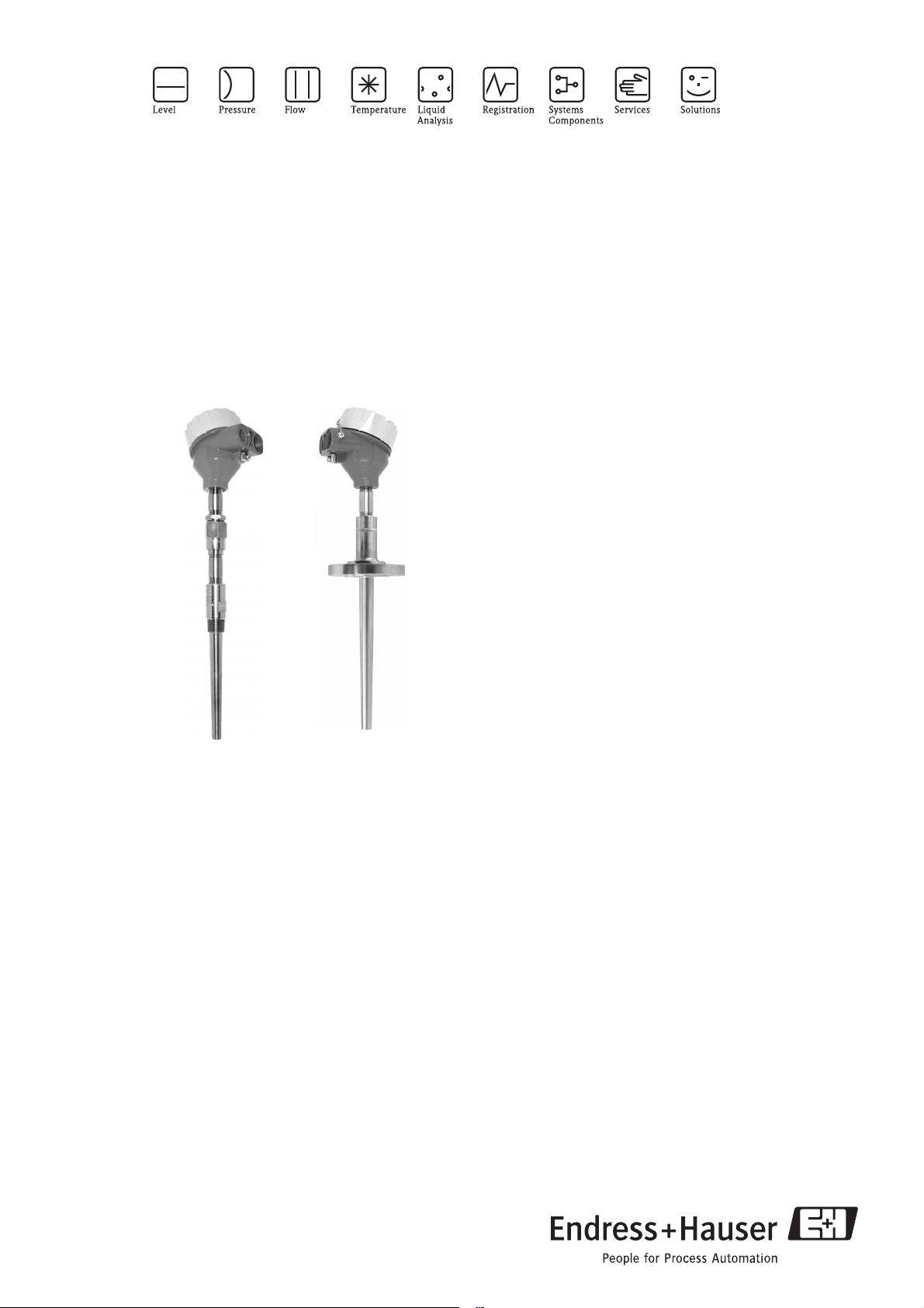
The Omnigrad S TC66 is an industrial thermometer (thermocouple TC: K or J) with a replaceable inset, a neck and a thermowell from bar stock.
It is developed for the use in the chemical, petrochemical and
energy industries, but suitable also for other generic heavy duty
applications.
In compliance to EN 50014/18/20 (ATEX certification) it is
therefore particularly suitable also for hazardous areas.
When required, it’s also available with a transmitter
(PCP, HART® or PROFIBUS-PA®) into the housing.
The process connection of the thermowell is threaded or
flanged in compliance to the standard of process requirements.
Application areas
• Chemicals industry
• Energy industry
• Gas Processing industry
• Petrochemical industry
• General industrial services
TI289T/02/en
Features and benefits
• Several types of process connection
• Several type of materials available for the thermowells
• Customized immersion length
• Aluminium housing, with protection grade from IP66 to IP68
• Thermocouple with hot junction grounded or ungrounded in
mineral oxide cable (MgO cable) diameter: 3 or 6 mm
• PCP, HART® and PROFIBUS-PA®,
(4...20 mA 2-wire transmitters)
• The accuracy of the thermocouple TC (K (NiCr-Ni) and
J (Fe-CuNi)) are: Cl. 1 - 2 (EN 60584) or Cl. Special Standard (ANSI MC96.1)
• The thermocouple TC (K or J) are available in single or double
element
• ATEX II 2 GD EEx-d IIC certification
• ATEX II 1/2 GD EEx d IIC certification
4 0
Page 2
Omnigrad S -TC66
Function and system design
Measuring principle The thermocouple (TC) thermometer’s sensing element consists of two metal wires that are homogeneous but
different one from the other and insulated along their entire length. The two wires are welded together at one
end, known as the “measurement or hot junction”. The other end, where the wires are free, is known as the
“cold or reference junction” and is connected to a electromotive force measurement circuit where the force is
generated by the different thermoelectric power of each of the thermocouple’s wires if there is a temperature
difference between the hot joint (T1) and the cold joint (Seebeck effect). The cold junction has to be “compensated” with reference to the temperature of 0°C (T0). The function that links the electromotive force to the
temperatures T1 and T0 is a curve whose characteristics depend on the materials used in the construction of
the thermocouple. Some thermocouples curves, and particularly those most reliable for the purposes of industrial readings, are those compliant with standards DIN EN 60584 and ANSI MC96.1.
Equipment architecture The construction of the TC66 temperature sensor is based on the following standards:
• EN 50014/18 (housing)
• Neck (1 or 2 nipple and 1 "3 union")
• EN 60584 (insert).
• Thermowells standard like: ASTM, DIN, ESSO, ENI, MONTEDISON, ENEL, etc.
The housing is in painted aluminium alloy; it is suitable to contain a transmitter and/or the ceramic block of the insert; the
“Ingress Protection” is from IP66 to IP68.
The neck composed by one or two nipple and one "3 union",
standard or EEx- execution, it is the exstension between the
head and the thermowell.
The hot junction of the thermocouple (type K or J) are positioned close to the tip of the probe. The thermocouple is available in two versions: grounded or ungrounded hot junction.
The electrical structure of the thermocouple always complies
with EN 60584/61515 or ANSI MC96.1/ASTM E585 standard rules.
The thermowell is from bar stock, with wetted part, conical,
straight or tapered. The process connection is: threaded or
flanged, in some case it can be to weld also.
Material & Weight
Operating conditions
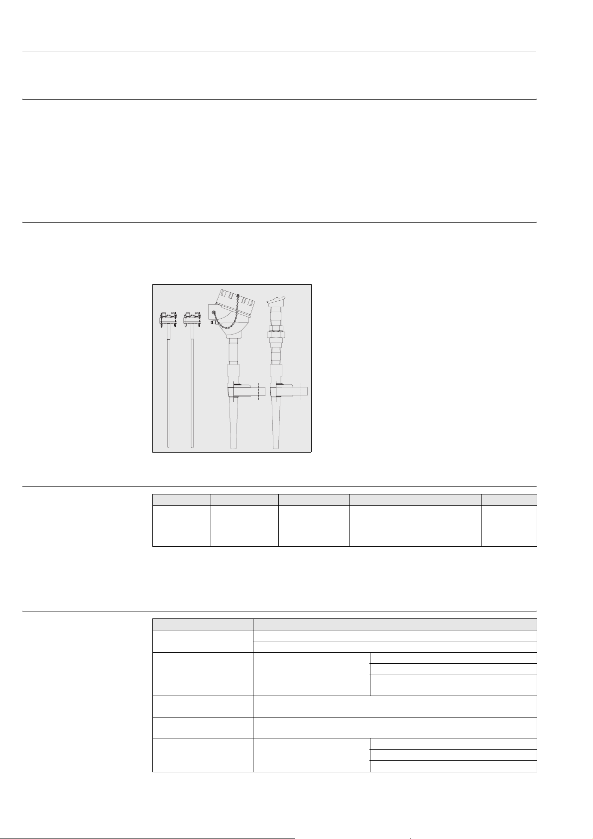
Fig. 1: TC66 with the various types of process connections and end parts of the probe
Housing Insert Neck Thermowell Weight
aluminium
epoxy coated
sheath in:
SS 316L/1.4404
Inconel®600/2.48
16
nipple and 3 union :
SS 316/1.4401 or
A105
thermowells: SS 316/1.4401, SS 316Ti
/1.4571, (Hastelloy C276/2.4819,
Monel® 400/2.4360, Inconel®
600/2.4816.)
From 1.5 to 5.0
kg for standard
options
Performance
Operating condition or test Product type or rules Value or data of test
Ambient temperature housing (without head-mounted transmitter -40÷130°C
housing (with head-mounted transmitter) -40÷85°C
Process temperature It is restricted by the thermowell
Process pressure (Maximum) The pressure values to which the thermowell can be subjected at the various tempera-
Maximum flow velocity The highest flow velocity, (of the stream or of the fluid), tolerated by the thermowell,
Shock and vibration resistance
test
material:
tures are illustrated by the drawings in fig. 2.
diminishes with increasing lengths, of the thermowell/probe exposed (fig. 2).
TC Inset in according to the rule
IEC 60751:
< 600°C SS 316L/1.4404
< 800°C SS 316Ti/1.4571
< 1100°C Hast.® C276/2.4819 -
Inc.600®/2.4816
Acceleration 3 g of peak
Frequency from 10Hz to 500Hz and back
Time test 10 hours
2 Endress+ Hauser
Page 3
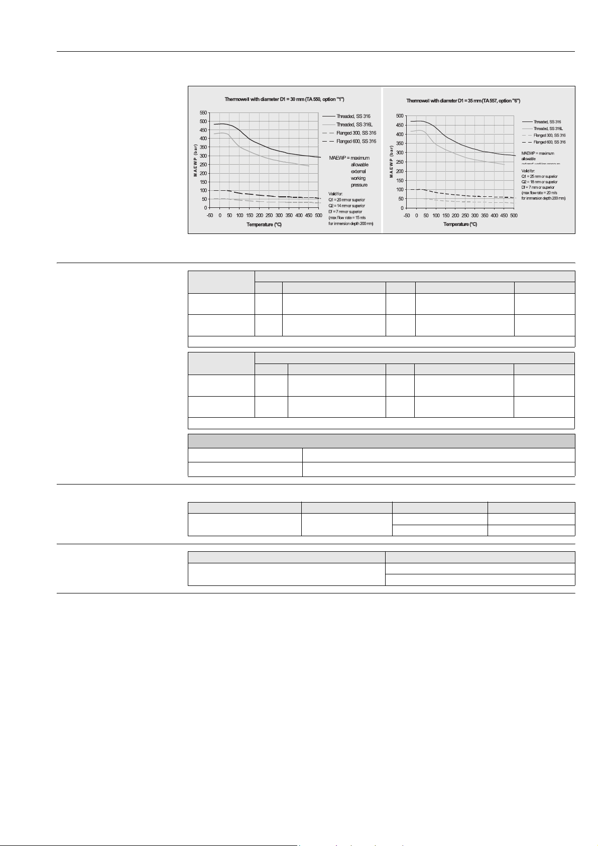
Fig. 2: Pressure/temperature grafic for thermowell from bar stock
Omnigrad S -TC66
Accuracy
Thermocouple
and range °C
J (Fe-CuNi)
-40° ... 750°C
K (NiCr-Ni)
-40 ... 1200°C
Thermocouple
and range °C
J (Fe-CuNi)
0 ...750°C
K (NiCr-Ni)
0...1250°C
Others errors
Transmitter maximum error See the corresponding documentation (codes at the end of the document)
Display maximum error 0.1% FSR + 1 digit (FSR = Full Scale Range)
Class Max deviation Class Max deviation Cable colors
2 +/-2.5°C (-40...333°C)
+/-0.0075 |t| (333...750°C)
2 +/-2.5°C (-40...333°C)
+/-0.0075 |t| (333...1200°C)
ItI = absolute temperature value in °C
Class Max deviation Class Max deviation Cable colors
Stand-
ard
Stand-
ard
+/-2.2°C (0...293°C)
+/-0.75%o(293...750°C)
+/-2.2°C (0...293°C)
+/-0.75%o(293...1250°C)
ItI = absolute temperature value in °C
EN 60584
1 +/-1.5°C (-40...375°C)
+/-0.004 |t| (375...750°C)
1 +/-1.5°C (-40...375°C)
+/-0.004 |t| (375...1000°C)
ANSI MC96.1
Special +/-1.1°C (0...275°C)
+/-0.4%o(275...750°C)
Special +/-1.1°C (0...275°C)
+/-0.4%o(275...1250°C)
Response time Tests, with the TC insert, in water at 0.4 m/s (according to IEC 60751) from 23 to 33°C:
Stem diameter of the insert Sensing element type Temperature of test Response time
Insulation
SS 316 - d. 6 mm K (NiCr-Ni)
J (Fe-CuNi)
Measurement Insulation type Result
Insulation resistance between terminals and probe sheath
according to EN 60584, test voltage 500 V
t
50
t
90
> 1GΩ at 25°C
> 5 MΩ at 500°C
2,5 s
7,0 s
+ black
- white
+ green
- white
+ black
- red
+ yellow
- red
Self heating Negligible when the E+H iTEMP® transmitters are employed.
Endress+Hauser 3
Page 4
Omnigrad S -TC66
Installation
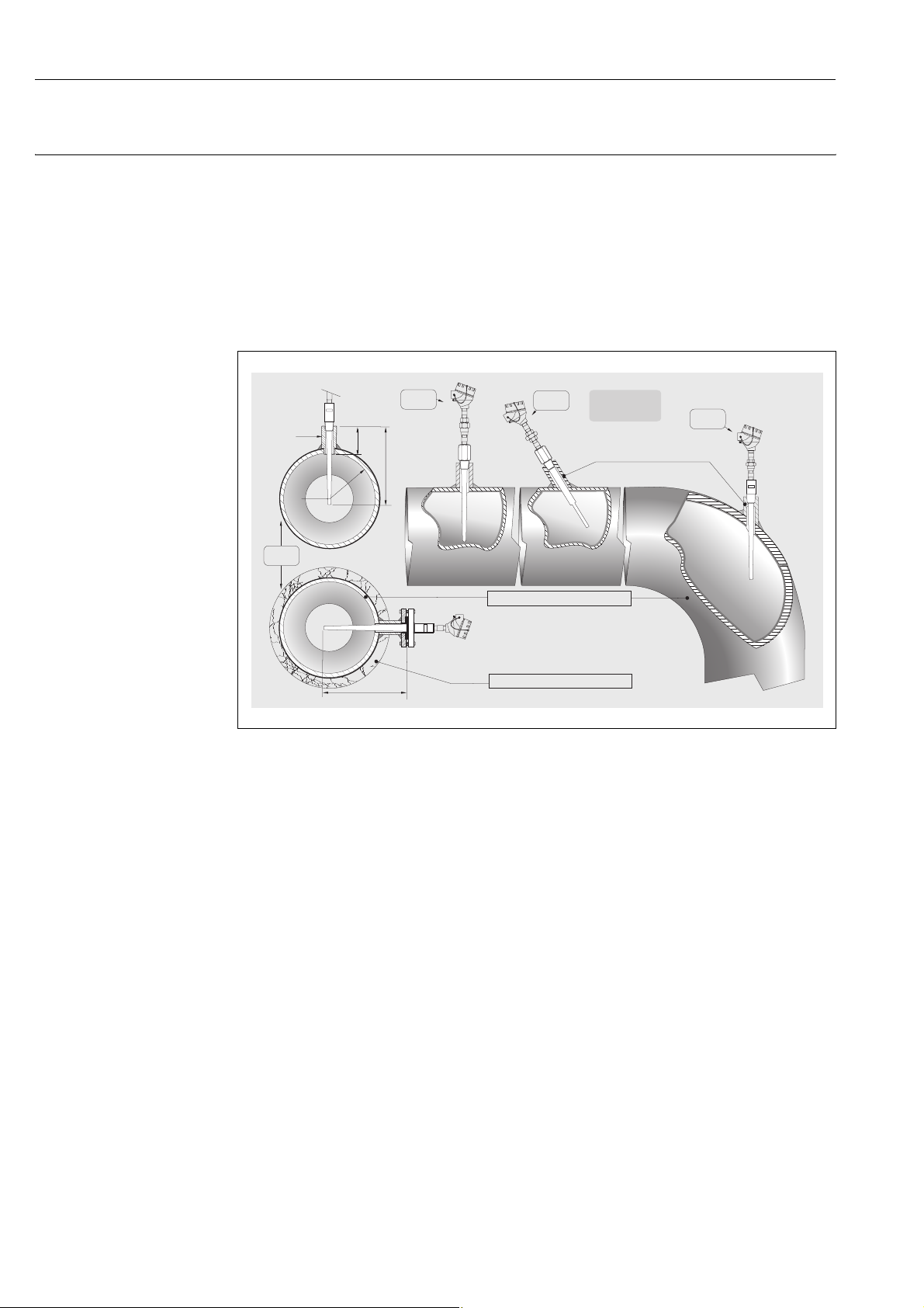
The TC66 can be installed on pipes, tanks or other heavy duty applications, by means of threaded or flanged
connections. The counterparts for process connections and gaskets, when required, are not supplied with the
sensor and must be purchased separately by the user. The immersion length must take into account all the
parameters of the thermometer and the process to measure. If the immersion is too low, an error may be generated in the temperature recorded due to the lower temperature of the process fluid near to the walls and heat
transfer, which takes place through the sensor stem. The incidence of such an error can be not negligible if
there is a big difference between the process temperature and the ambient temperature. To prevent measuring
errors of this kind, it is advisable to use thermowells with a small diameter and an immersion length (U) of at
least 100÷150 mm. In small section ducts the tubing’s axis must be reached and preferibly slightly exceeded
by the tip of the probe (see fig. 3A-3C). Insulation of the outer part of the sensor reduces the effect produced
by a low immersion. Alternatively, it is also possible to adopt a tilted installation (see fig. 3B-3D).
h ≈ d
L > D/2+h
welded coupling
B
Ød
ØD
A
Fig. 3: Installation examples
C
h
L
PIPE METALLIC SHEATH
L
THERMAL INSULATING
L
D
For a best installation, in the industries, it's better to follow the rule: h ( d, L > D/2 + h. As far as corrosion is
concerned, the base material for parts in contact with the fluid is able to withstand the most common corrosive
agents up to the highest temperatures. Even the nipples and 3 elements coupling supplied with the connection
fitting of the instrument are able to withstand a wide range of aggressive substances. With regard to corrosion,
the base material of the wetted parts (SS 316L, SS 316Ti, Hastelloy
® C276 or Inconel®600) can tolerate the
common corrosive media right up to even the highest temperatures.
For further information on specific applications, contact the E+H Customer Service Department. Disassembled
components of the sensors must be reassembled with the recommended clamping torques in order to ensure
the appropriate IP protection class within the sensor-housing coupling.
4 Endress+ Hauser
Page 5
Omnigrad S -TC66
System components
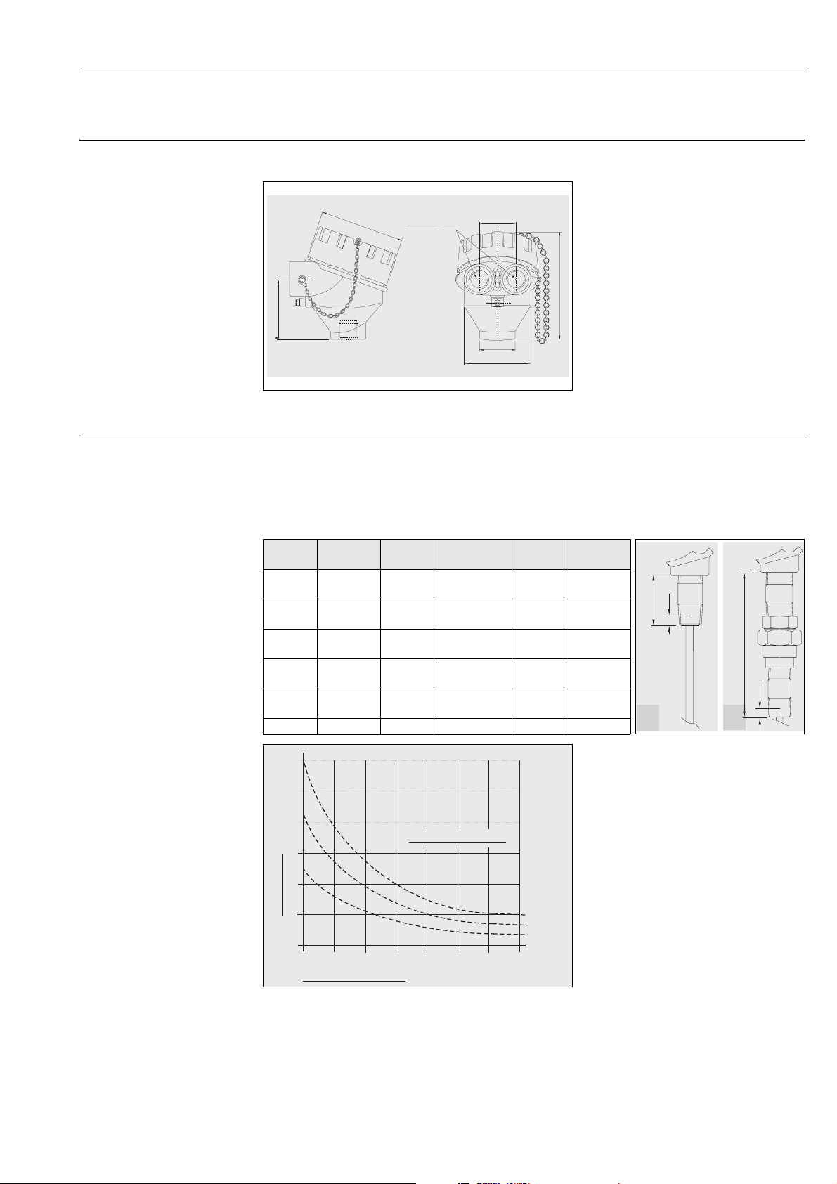
Housing The protection housing, our "TA21H", commonly referred to the “connection head”, is used to contain and
protect the terminal block or the transmitter and to join the electric connections to the mechanical component.
The TA21H used for the TC66 is compliant
with EN 50014/18 and EN 50281-1-1, EN
½ NPT, NPT
Ø90
64
Fig. 4: Housing TA21H
¾
G ½", M20x1.5
39
ø38
ø72
Extension neck A special extension is inserted between the husing and the thermowell connection, this part is calledneck. The
neck is constituted by a tube assembled to hydraulic hardware (nipples or joints) that is suitable to allow the
adjustment of the sensor to the thermowell.
In addition to the standard versions listed below, it is also possible to order the extension neck by specifying
the desired length (see “Sales structure” chart at the end of this document). In the TC66 the standard lengths
(N) and the versions of the extension neck can be selected among the following options:
Tp Material N lengthmmThread C
N 316 69 1/2" NPT M 8 A
N 316 109 1/2" NPT M 8 A
mm
50281-1-2 standards (EEx-d certification for
explosion proof type of protection).
The matching of the head with the extension
below the head and the cover (threaded)
ensures a degree of protection from IP66 to
115
~
IP68.
The head also has a chain to connect the body
to the cover, which facilitates the use of the
instrument during the maintenance on systems. The single or double threaded electrical
cable entry can be: M20x1.5, 1/2” NPT or
3/4” NPT, G1/2".
Neck
dwg type
N
C
N
NUN 316 148 1/2" NPT M 8 F
NA105691/2" NPT M8 A
N A105 109 1/2" NPT M 8 A
NUN A105 148 1/2" NPT M 8 F
As illustrated by the drawing in fig. 5, the
length of the extension neck may influence
the temperature in the head. It is necessary
that this temperature is kept within the limit
°C
30
25
values defined in the paragraph “Operating
20
Process temperature
15
Conditions”.
Before choosing the connection, it is better to
verify this graphic and therefore to choose a
suitable extension to avoid the heating of the
10
Head heating
5
0
100 125 150 175 20075
Neck extension length
225 250
570°C
400°C
220°C
mm
head.
Fig. 5:Heating of the head caused by the process temperature
A
C
F
Endress+Hauser 5
Page 6
Omnigrad S -TC66
1
-
+
-
+
1
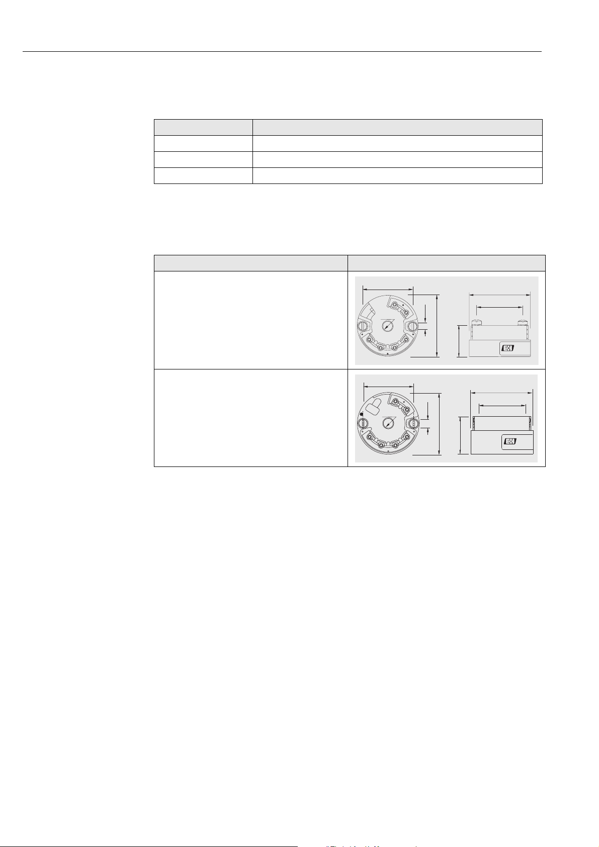
Electronic head transmitter The required type of output signal can be obtained by choosing the correct head mounted transmitter.
Endress+Hauser supplies “state-of-the-art” transmitters (the iTEMP® series) built in 2-wire technology and
with 4…20 mA output signal, HART® or PROFIBUS-PA®. All of the transmitters can be easily programmed
using a PC:
Head transmitter Communication software
PCP TMT181 ReadWin® 2000
HART
® TMT182 ReadWin® 2000, FieldCare, Hand held module DXR275, DXR375
PROFIBUS PA® TMT184 FieldCare
In the case of PROFIBUS-PA® transmitters, E+H recommends the use of PROFIBUS® dedicated connectors.
The Weidmüller type is provided as a standard option. For detailed information about transmitters, please refer
to the relevant documentation (refer to TI codes at the end of the document). If a head-mounted transmitter
is not employed, the sensor probe may be connected through the terminal block to a remote converter (i.e.
DIN rail transmitter). The customer may specify the configuration desired during the order phase. The headmounted transmitters available are:
Description Dwg
TMT181: PCP 4…20 mA.
The TMT181 is a PC programmable transmitters
TMT182: Smart HART®.
The TMT182 output consists of 4…20 mA and HART®
superimposed signals.
Ø33
2
Ø 6.5
6
5
Ø 4.5
Ø44
3
4
22.5
Ø44
Ø33
TMT184: PROFIBUS-PA®.
For the TMT184, with PROFIBUS-PA® output signal,
the communication address may be set via software or via
mechanical dip-switch.
Ø33
+
2
1
6
-
Ø 6.5
8
+
-
5
Ø 4.5
Ø44
3
4
26.8
Ø44
Ø33
6 Endress+ Hauser
Page 7
Omnigrad S -TC66
A
U
T
Ø Q2
Ø Q1
Ø Q2
Ø Q1
Ø D1
Ø Df
Ø D1
Ø Df
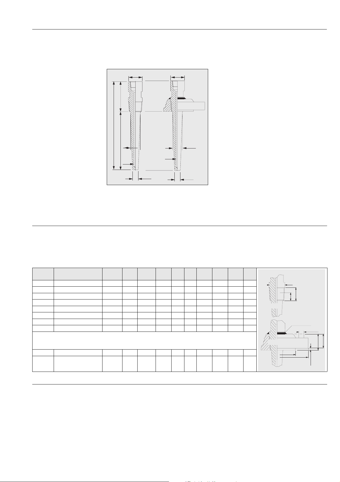
Thermowell The thermowell is the component of the TC66 that must tolerate most of the mechanical stress transmitted by
the process.
It is made from a round bar and supplied in different materials and dimensions, according the chemical/physical characteristics of the process: corrosion, temperature, pressure and speed of the fluid.
ØD1
ØD1
The thermowell consists of three parts:
•the extension neck (indicated as T), usually with a cylindrical shape (and standard diameters of 30 or 35 mm and
lengths of 70/100 mm), represents the external part of
the thermowell and is connected with the head of the
probe by means of a neck (usually a nipple)
•the immersed part (identified as U), with a conical or
cylindrical shape (the standard diameter of the area below
the fitting is 20 or 25 mm), is situated next to the process
connection in direct contact with the process fluid
•the threaded or flanged process connection represents
ØDf
ØQ1
ØDf
ØQ1
the part inserted between the extension and the immersed
part and guarantees the mechanical and hydraulic sealing
of the thermometer and plant.
The external finishing of the thermowell stem is available
with a standard value of Ra < 1.6 μm (different finishes
ØQ2
ØQ2
are available on request).
Fig. 6: Thermowell with threaded or flanged process connection
Warning:
#
The total standard length (A) of the thermowell must never exceed 1200 mm (that represents the maximum
drilling limit; higher lengths are available only on request).
Process connection The standard process connections are threaded or flanged. When the process connection is threaded the mate-
rial of connection is the same at the thermowell instead, when the process connection is flanged the material
can be different: SS 316/1.4401or ASTM A105/St 52.3.
When it is necessary to have a flange in special material, more resistant at the corrosion (example Hastelloy
®C276), it is cheaper to choose an economic version composed by a flange in SS316/1.4401 with on wetted
part platted a disk in Hastelloy ®C276/2.4819 (this solution is very less expensive).
Type Thread or Flange Ø
D!
Flange 1” ANSI 150 RF SO // 50,8 107,9 15,9 4 1,6 17,5 // // //
Flange 1” ANSI 300 RF SO // 50,8 123,8 19,0 4 1,6 27,0 // // //
Flange 1” ANSI 600 RF SO // 50,8 123,8 19.0 4 6,4 // 27,0 // //
Flange 1” 1/2 ANSI 150 RF SO // 73,0 127,0 15,9 4 1,6 22,2 // // //
Flange 1” 1/2 ANSI 300 RF SO // 73,0 155,6 22,2 4 1,6 30,2 // // //
Flange 1” 1/2 ANSI 600 RF SO // 73,0 155,6 22.2 4 6,4 // 31,7 // //
Flange 2” ANSI 300 RF SO // 92,1 165.1 19,0 8 1,6 33,3 // // //
Flange 2” ANSI 600 RF SO // 92,1 165,1 19,0 8 6,4 // 36,5 // //
All the dimension are in "mm"
Thread 1/2" NPT ≥ 21,4 // // // // // // // 19,9 8,1
Thread 3/4" NPT ≥ 26,7 // // // // // // // 20,2 8,6
Ø
D2ØD3
Ø
D4D4Nr
S1 S2 S3 A A1
THREAD
FLANGE
D1
A1
D2
A
WELDED
D3
On request, it is possible to select also different materials, finishings and connections.
D4
S3
S2
S1
Probe In the TC66 the measuring probe are two:
• the TPC100 (for general purpose application)
• the TPC300 (ATEX EEx d application)
Both of the probe are made in mineral insulated cable (MgO), with sheath in AISI316/1.4401 or Inconel®600.
The Immersion length (U) of the thermometer can be chosen within a standard range from 50 to 1000 mm
(see "Warning" in the "thermowell" section).
The thermometer with a Immersion length (U) > 1000 mm can be supplied after a technical verification of the
specific applications from our technical office in the E+H Customer Service Department.
Endress+Hauser 7
Page 8
Omnigrad S -TC66
+
-
+
-
+
-
-
+
-
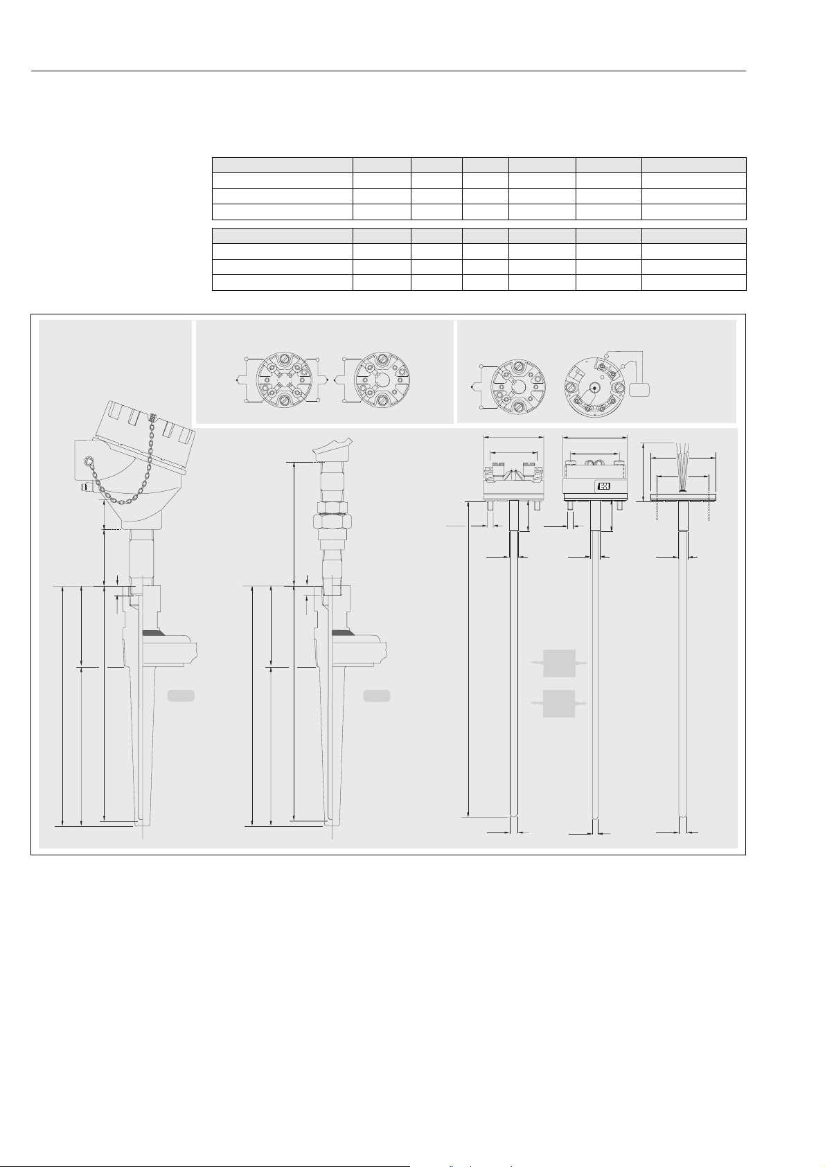
For replacement of the insert, it is necessary to refer the following table to have the IL (applicable only to standard thickness well bottoms). The immersion length of the insert spare part (IL) is calculated adding the total
length of the thermowell (A = U + T) and the length of neck (N) used. Please refer the following table:
Insert general purpose Ø, ..mm N , tp. N, mm N, material N, thread IL, (mm)
TPR100 6 N 69 A105/SS316 1/2"NPT M IL = U+T+ 69 + 41
TPR100 6 N 109 A105/SS316 1/2"NPT M IL = U+T+ 109 + 41
TPR100 6 NUN 148 A105/SS316 1/2"NPT M IL = U+T + 148 + 41
Insert ATEX EEx d Ø, ..mm N , tp. N, mm N, material N, thread IL, (mm)
TPR300 6 N 69 A105/SS316 1/2"NPT M IL = U+T + 69 + 41
TPR300 6 N 109 A105/SS316 1/2"NPT M IL = U+T + 109 + 41
TPR300 6 NUN 148 A105/SS316 1/2"NPT M IL = U+T + 148 + 41
ELECTRICAL DIAGRAM ON TERMINAL BLOCK
2xTC
2°TC1°TC
2 wires
41
N
N
C
T
IL
U
A
N
C
IL
UTA
1xTC
1°TC
2 wires
NUN
M4x1
...WITH
TERMINAL
BLOCK
1°TC
Ø8
Ø42
Ø33
40
M4x1
TPC300
ATEX
Certified
TPC100
General
Purpose
or
... WITH
TRANSMITTER
+
1
6
5
4
Ø44
Ø33
40
Ø8
-
2
mA
3
Ø42
Ø33
75
Ø8
Ø3
Ø6Ø6
Fig. 7: Functional components, standard electrical diagrams (ceramic terminal block)
8 Endress+ Hauser
Page 9

Omnigrad S -TC66
Certificates & approvals
Ex approval • ATEX Certificate CESI 05ATEX038 for explosion proof type of protection: ATEX II 2 GD EEx-d IIC T6..T5
T85°...T100°C. ATEX II 1/2 GD EEx-d IIC T6..T5 T85°...T100°C. The TC66 is 4 marked.
With regards to the NAMUR NE 24 certificate and the Manufacturer’s Declaration according to the standard
EN 50018, EN 50020, EN 50281-1-1, EN 50281-1-2, E+H Customer Service will be able to provide further
detailed information.
PED approval The Pressure Equipment Directive (97/23/CE) is respected. As paragraph 2.1 of article 1 is not applicable to
these types of instruments. The 4 mark according to PED Directive is not requested.
Material certification The material certificate EN 10204 3.1 can be directly selected from the sale structure of the product and refers
to the parts of the sensor in contact with the process fluid.
Other types of certificates related to materials can be requested separately.
The “short form” certificate includes a semplified declaration with no enclosures of documents related to the
materials used in the construction of the single sensor and guarantees the traceability of the materials through
the identification number of the thermometer.
The data related to the origin of the materials can subsequently be requested by the client if necessary.
Test on thermowell The pressure tests are carried out at ambient temperature in order to verify the resistance of the thermowell to
the specifications indicated by the norm ASME PTC 19.3.
With regards to the thermowells that do not comply with this norm (with a reduced tip, a tapered tip on a 9
mm tube, special dimensions, etc.), the pressure of the corresponding straight tube with similar dimensions is
verified. The sensors certified for use in Ex Zones, are always tested to pressure according to the same criterions.
Further details
Maintenance The Omnigrad S TC66 thermometers do not require any specific maintenance.
In the case of ATEX certified components (transmitter, insert or thermowell) please refer to the corresponding
specific relevant documentation (at the end of the document).
Endress+Hauser 9
Page 10
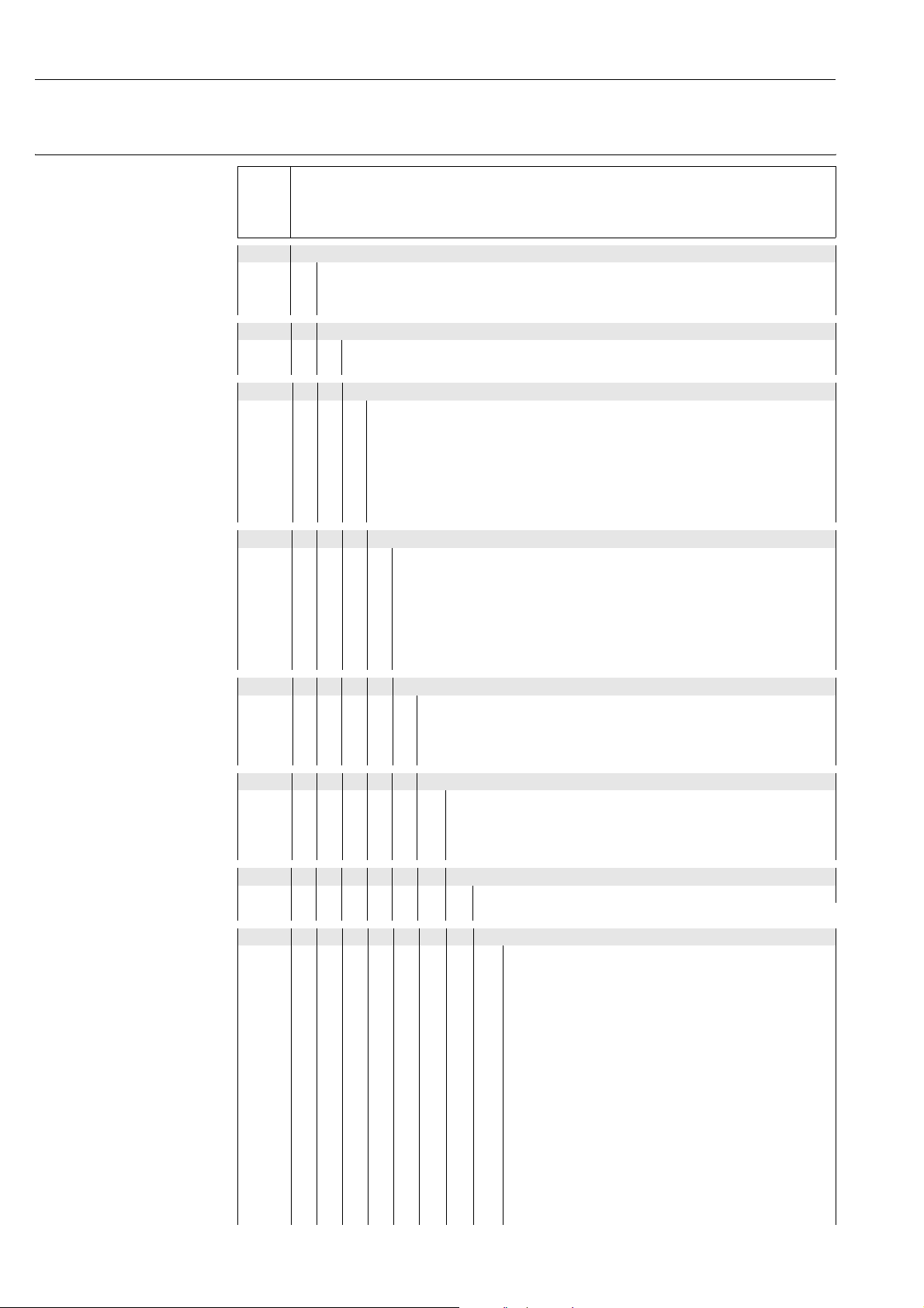
Ordering information
Omnigrad S -TC66
Sales structure
TC66- Omnigrad S TC66. ATEX EEx d certified.
Thermocouple thermometer complete of the thermowell from bar stock.
Replaceable mineral inset: gounded or ungrounded.
Terminal head connection with epoxy coating, IP66-IP68
Two operating and measurement ranges: from -40 to 750°C (with TC J); -40 to 1200°C (with TC K)
Approval:
Non-harzarus area
A
*ATEX II 2 GD EEx d IIC
E
*ATEX II 1/2 GD EEx d IIC
M
Head, material, IP grade
TA21H Alu. epoxy coating, , IP66 /IP68
A
Special version, to be specified
Y
Cable entry
1 x 1/2 NPT
A
2 x 1/2 NPT
B
1 x 3/4 NPT
C
2 x 3/4 NPT
D
1 x M20 x1,5
E
2 x M20 x1,5
F
Special version, to be specified
Y
Neck length N; Material; Fitting
69 mm, SS 316, N, 1/2"NPT M
B
109 mm, SS 316, N, 1/2"NPT M
C
148 mm, SS 316, NUN, 1/2"NPT M
E
69 mm, A105, N, 1/2"NPT M
F
109 mm, A 105, N, 1/2"NPT M
G
148 mm, A 105, NUN, 1/2"NPT M
J
Special version, to be specified
Y
Thermowell material:
SS 316Ti
B
SS 316
C
SS 316L
D
Special version, to be specified
Y
Extension T; D1; Df; Q1; Q2
70 mm, 30 mm, 7 mm, 20 mm, 14 mm,
1
75 mm, 35 mm, 7 mm, 24 mm, 14 mm,
2
100 mm, 35 mm, 7 mm, 25 mm, 18 mm,
6
Special version, to be specified
9
Insertion Length IL:
mm
X
Special version, to be specified
Y
Process connection:
11
22
CA
CB
CC
CD
CE
CF
CG
CH
CI
CK
CL
CM
CQ
CS
thread 1/2" NPT - M
thread 3/4" NPT - M
1" ANSI 150 RF SO, A105
1" ANSI 150 RF SO, SS 316
1" ANSI 300 RF SO, A105
1" ANSI 300 RF SO, SS 316
1" ANSI 600 RF SO, A105
1" ANSI 600 RF SO, SS 316
1"1/2 ANSI 150 RF SO, A105
1" 1/2 ANSI 150 RF SO, SS 316
1" 1/2 ANSI 300 RF SO, A105
1" 1/2 ANSI 300 RF SO, SS 316
1" 1/2 ANSI 600 RF SO, A105
1" 1/2 ANSI 600 RF SO, SS 316
2" ANSI 300 RF SO, A105
2" ANSI 600 RF SO, A105
10 Endress+ Hauser
Page 11
2" ANSI 300 RF SO, SS 316
CT
2" ANSI 600 RF SO, SS 316
CV
Special version, to be specified
YY
Head transmitter; Range:
Flying leads
F
Terminal block
C
TMT181-A, PCP, from...to...°C, 2-wire, isolated
P
TMT181-B, PCP ATEX, from...to...°C, 2-wire, isolated
Q
TMT182-A, HART®, from...to...°C, 2-wire, isolated
R
TMT182-B, HART ®ATEX, from...to...°C, 2-wire, isolated
T
TMT184-A, Profibus PA®, from...to...°C, 2-wire, isolated
S
TMT184-B, Profibus PA® ATEX, from...to...°C, 2-wire, isolated
V
THT1 separate item
1
TC Accuracy; Material;
1x type K cl. 1 special; Inconel®600
A
2x type K cl. 1 special; Inconel®600
B
1x type J cl. 1 special; SS 316L
E
2x type J cl. 1 special; SS 316L
F
Special version, to be specified
Y
TC Standard; Hot Junction;
EN 60584; ungrounded
1
EN 60584; grounded
2
ANSI MC96.1; ungrounded
3
ANSI MC96.1; grounded
4
Special version, to be specified
9
Additional options
Not needed
0
Special version, to be specified
Y
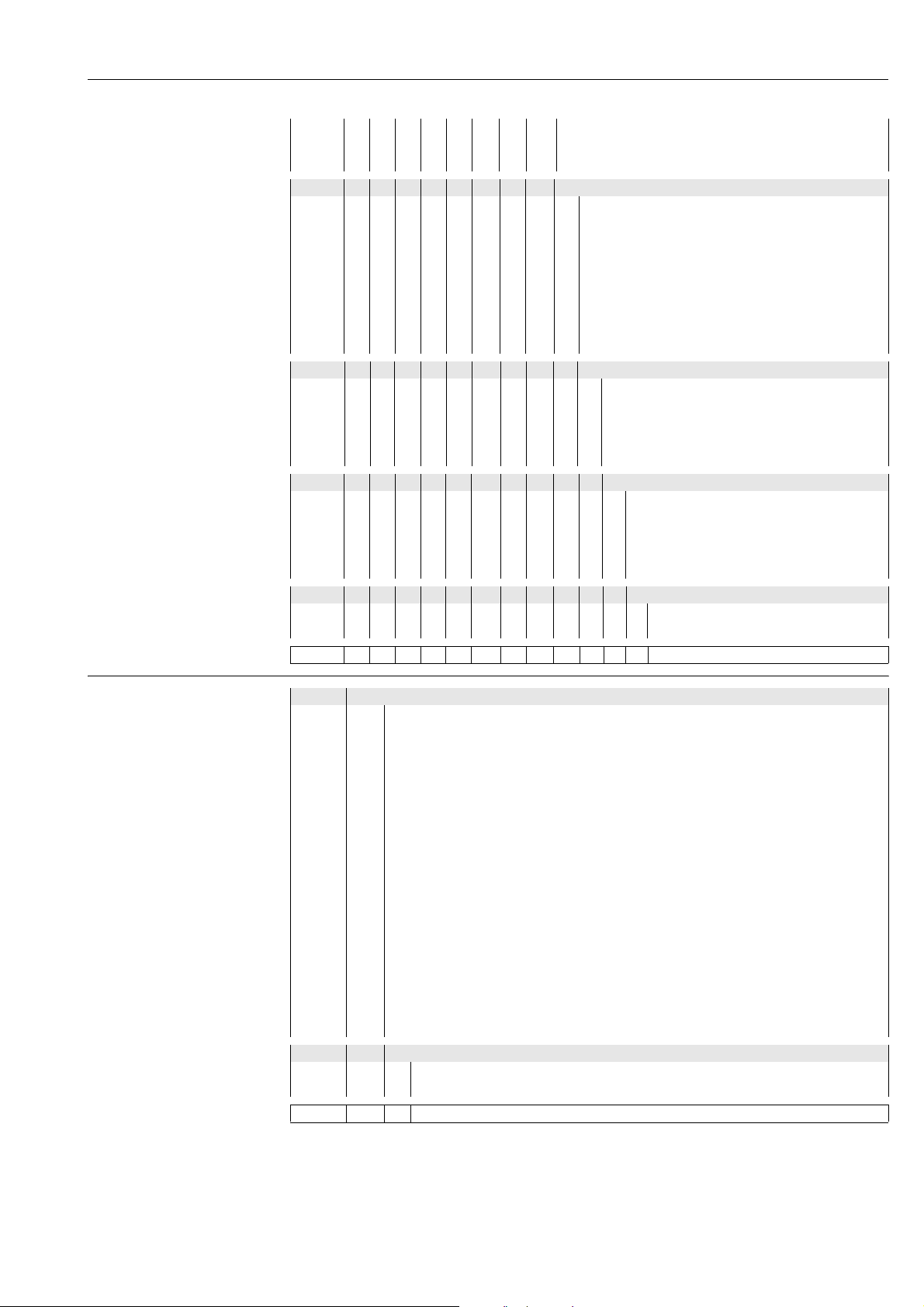
TC66- ⇐ Order code (complete)
Omnigrad S -TC66
Sales structure
THT1 Model and version of the head transmitter
TMT181-A PCP, 2-wire, isolated, programmable from...to...°C
F11
TMT181-B PCP ATEX, 2-wire, isolated, programmable from...to...°C
F21
TMT181-C PCP FM IS, 2-wire, isolated, programmable from...to...°C
F22
TMT181-D PCP CSA, 2-wire, isolated, programmable from...to...°C
F23
TMT181-E PCP ATEX II3D, 2-wire, isolated, programmable from...to...°C
F24
TMT181-F PCP ATEX II3D, 2-wire, isolated, programmable from...to...°C
F25
TMT182-A HART®, 2-wire, isolated, programmable from...to...°C
L11
TMT182-B HART® ATEX, 2-wire, isolated, programmable from...to...°C
L21
TMT182-C HART® FM IS, 2-wire, isolated, programmable from...to...°C
L22
TMT182-D HART® CSA, 2-wire, isolated, programmable from...to...°C
L23
TMT182-E HART® ATEX II3D, 2-wire, isolated, programmable from...to...°C
L24
TMT182-F HART® ATEX II3D, 2-wire, isolated, programmable from...to...°C
L25
TMT184-A PROFIBUS-PA®, 2-wire, programmable from...to...°C
K11
TMT184-B PROFIBUS-PA® ATEX, 2-wire, programmable from...to...°C
K21
TMT184-C PROFIBUS-PA® FM IS, 2-wire, programmable from...to...°C
K22
TMT184-D PROFIBUS-PA® CSA, 2-wire, programmable from...to...°C
K23
TMT184-E PROFIBUS-PA® CSA, 2-wire, programmable from...to...°C
K24
TMT184-F PROFIBUS-PA® ATEX II3D, 2-wire, isolated, programmable from...to...°C
K25
Special transmitter
YYY
Application and services
Assembled into position
1
Special version
9
THT1- ⇐ Order code (complete)
Endress+Hauser 11
Page 12

Supplementary documentation
71105563
Brochure Field of activities - Temperature measurement FA006T/09/en
Temperature head transmitter iTEMP® PCP TMT181 TI070R/09/en
Temperature head transmitter iTEMP® HART® TMT182 TI078R/09/en
Temperature head transmitter iTEMP® PA TMT184 TI079R/09/en
Industrial thermometers, RTD and Thermocouples TI236T/02/en
TC insert for temperature sensors - Omniset TPC100 TI278T/02/en
TC insert for temperature sensors - Omniset TPC300 (to be released) TI291T/02/en
Safety instructions for use in hazardous areas (TPC300, to be released) XA017T/02/en
TC thermometers Omnigrad TSC - General information TI090T/02/en
International Head Quarter
Endress+Hauser
GmbH+Co. KG
Instruments International
Colmarer Str. 6
79576 Weil am Rhein
Germany
Tel. +49 76 21 9 75 02
Fax +49 76 21 9 75 34 5
www.endress.com
[email protected]
TI289T/02/en/07.05
FM+SGML6.0
 Loading...