

Page 1

TI00251T/09/en/14.13
71214661
Products Solutions Services
Technical Information
Omnigrad S
TAF11, TAF12x, TAF16
High temperature assemblies
With metal or ceramic protection tubes
Adjustable process connection
Thermocouple sensor types J, K, N, R, S, B
Application
TAF11
• Applicable for steel treatment (annealing), concrete furnaces and primaries.
It contains a single or double TC insert and a ceramic protection tube.
TAF12x
• The versions S/D/T are assemblies with single/double/triple ceramic protection
tubes, designed specifically for applications such as ceramic baking ovens,
brickworks, porcelain production and glass industries. They contain a single or
double TC insert in ceramic insulators.
TAF16
• Applicable for cement production, steel treatment, incinerators and fluidized bed
furnaces. The TAF16 contains a single or double TC insert and a metal or ceramic
protection tube.
Process temperatures:
• TAF11 up to +1600 °C (+2912 °F)
• TAF12 up to +1700 °C (+3092 °F)
• TAF16 up to +1700 °C (+3092 °F)
Your benefits
• Long lifetime by usage of innovative protection tube materials with increased wear
and chemical resistance
• Long term stable measurement due to sensor protection with non-porous materials
• Flexible product selection by modular design
• Optimized life cycle costs by means of replaceable spare parts
Page 2
TAF11, TAF12x, TAF16
ENDRESS+HAUSER
TMT 122
B
°C
C D
A
Function and system design
Measuring principle Thermocouples are comparatively simple, robust temperature sensors which use the Seebeck effect for
temperature measurement: if two electrical conductors made of different materials are connected at a
point, a weak electrical voltage can be measured between the two open conductor ends if the
conductors are subjected to a thermal gradient. This voltage is called thermoelectric voltage or
electromotive force (emf.). Its magnitude depends on the type of conducting materials and the
temperature difference between the "measuring point" (the junction of the two conductors) and the
"cold junction" (the open conductor ends). Accordingly, thermocouples primarily only measure
differences in temperature. The absolute temperature at the measuring point can be determined from
these if the associated temperature at the cold junction is known or is measured separately and
compensated for. The material combinations and associated thermoelectric voltage/temperature
characteristics of the most common types of thermocouple are standardized in the IEC 60584 and
ASTM E230/ANSI MC96.1 standards.
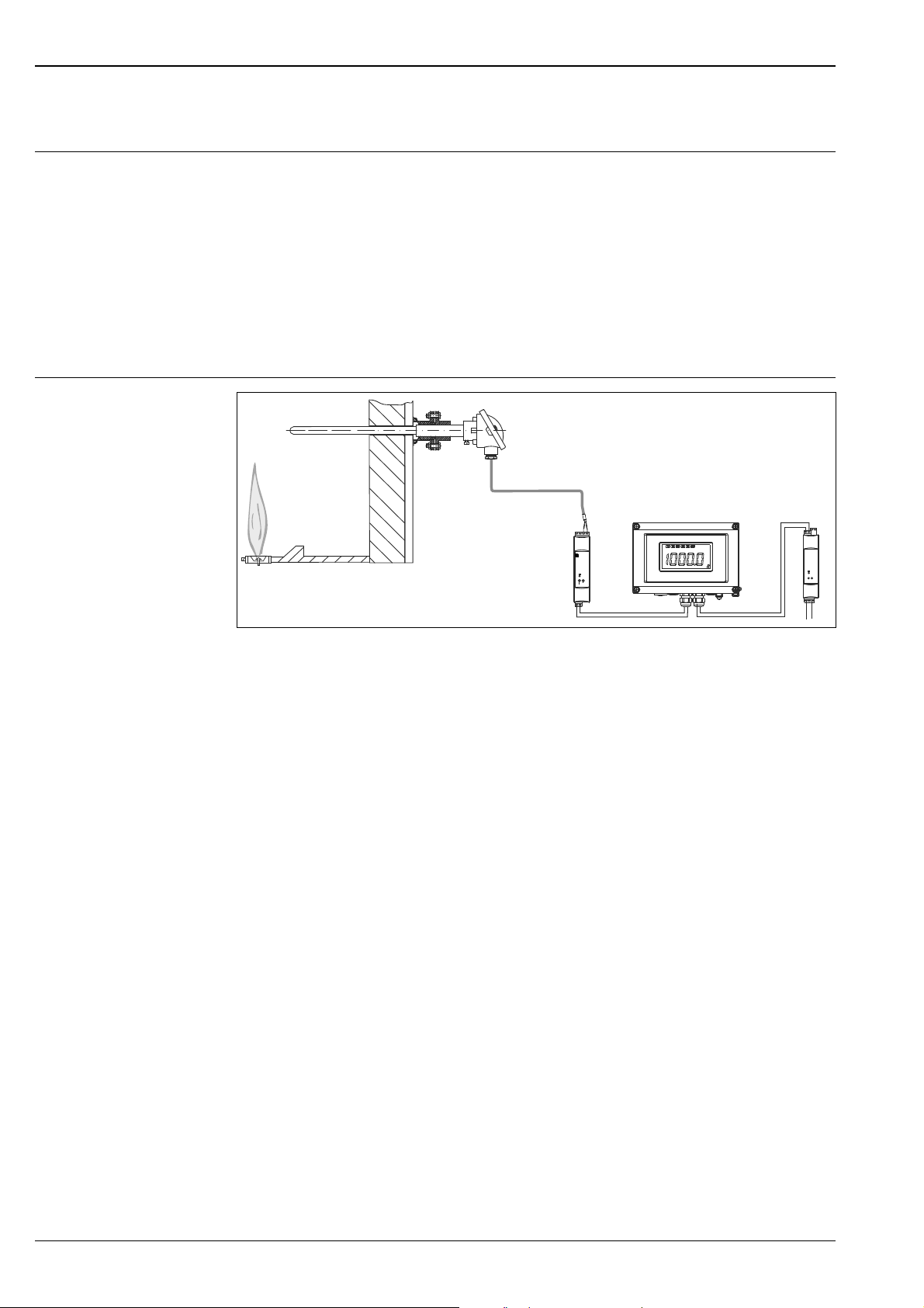
Measuring system
Example of an application
A Thermometer of the TAF series, installed in the reactor wall of a furnace
B Temperature transmitter iTEMP
of the
thermocouple thermometer and converts them into an analog 4 to 20 mA measurement signal.
C RIA16 field display unit
– The display unit records the analog measuring signal from the head transmitter and shows this on the
display. The LC display shows the current measured value in digital form and as a bar graph indicating a limit
value violation. The display unit is looped into the 4 to 20 mA circuit and gets the required energy from there.
More information on this can be found in the Technical Information (see "Documentation").
D Active barrier RN221N
– The RN221N active barrier (24 V DC, 30 mA) has an galvanically isolated output for supplying voltage to
loop powered transmitters. The universal power supply works with an input supply voltage of 20 to
250 V DC/AC, 50/60 Hz, which means that it can be used in all international power grids. More information
on this can be found in the Technical Information (see "Documentation").
®
DIN rail TMT12x. The two-wire transmitter detects the measurement signals
a0015182
2 Endress+Hauser
Page 3
TAF11, TAF12x, TAF16
Equipment architecture
a0015181
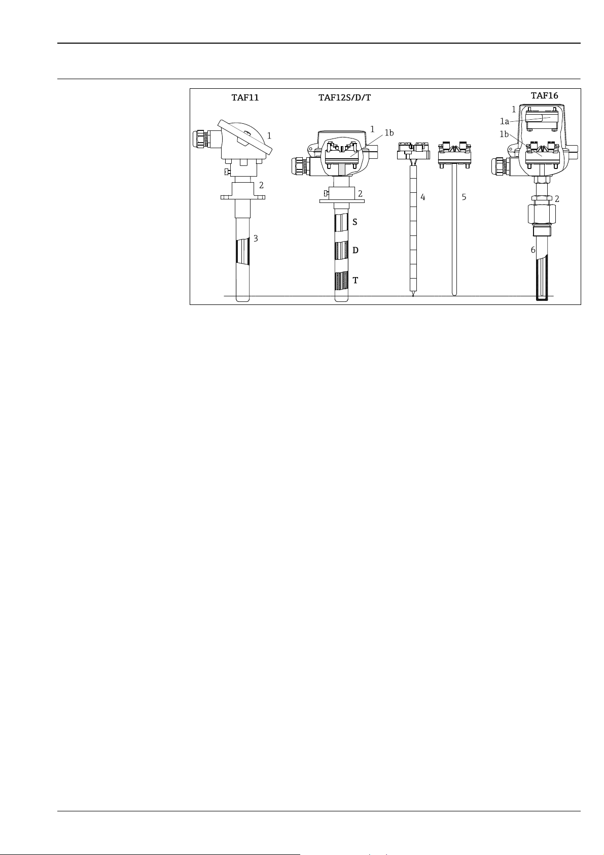
High temperature assemblies design
1
Terminal head DIN A (see left side) or DIN B (e.g.
see right side) with following available electrical
connections:
1a
– Terminal block DIN B with head transmitter
(only in high cover terminal head)
1b
–Terminal block (DIN B) or
– Flying leads, only with MgO insulated insert
2 Available process connections:
Stop flange according to DIN EN 50446,
adjustable flange, or gas-tight compression fitting
3 Ceramic protection tube (external sheath for
TAF11)
S
(Single) ceramic protection tube external sheath for
TAF12
D
(Double) ceramic protection tube external and middle
sheath for TAF12
T
(Triple) ceramic protection tube external, middle and
internal sheath for TAF12
45Measuring insert TPC200 with ceramic isolation
Measuring insert TPC100 with MgO insulation and
metallic sheath, selectable for TAF11 and TAF16
6 Metal or ceramic protection tube for TAF16
TAF series high temperature assemblies are manufactured according to international DIN EN 50446
standards. These products consist of a measuring insert, a protection tube, a metal sleeve (only TAF11/
TAF12x) and a terminal head, which contains a transmitter or terminal block as electrical connection.
Measuring insert
The measuring point of the thermocouple is located close to the tip of the insert. The operating
temperature ranges (→ ä 4) and permissible deviation limits of the thermoelectric voltages from the
standard characteristic (→ ä 5) vary according to the type of thermocouple used. The thermocouple
wires are inserted in appropriate high-temperature-resistant ceramic isolators or in a mineral
insulated insert.
Protection tube
Two types are commonly used in this type of assembly:
• Metallic protection tube, usually machined from tubes or bars.
• Ceramic protection tube.
The selection of the protection tube materials majorly depends on the following material properties,
which will directly influence the lifetime of the sensor:
•Hardness
• Chemical resistance
• Maximum operating temperature
• Wear/abrasion resistance
•Brittleness
• Porosity for process gases
• Creep resistance
Ceramic materials are commonly used for highest temperatures and, due to their hardness, for
applications with high abrasion rates. Attention has to be paid regarding the brittleness of these
materials when exposed to high mechanical loads inside the process. When using porous ceramics as
Endress+Hauser 3
Page 4
TAF11, TAF12x, TAF16
external protection sheath, an additional, non-porous inner protection sheath has to be used in order
to protect the noble sensor elements from contamination leading to temperature drift.
Metal alloys generally show higher mechanical resistance but lower maximum temperature limits and
less abrasion resistance. All metal alloys are non-porous and usually there is no need for an additional
inner protection sheath.
Metal sleeve and process connection
The TAF11 and TAF12 ceramic protection tubes are mounted into a metal sleeve which connects them
towards the terminal head. Also the process connection is fitted on the metal sleeve due to its higher
mechanical strength. The dimensions and material type for the sleeve are related to the process
temperatures and insertion length of the ceramic protection tubes.
All high temperature assemblies are available with an adjustable flange, stop flanges or gas tight
compression fittings.
Measuring range
Input Designation Measuring range limits
Thermocouples (TC)
as per IEC 60584,
part 1 - using an
Endress+Hauser -
®
iTEMP
temperature
head transmitter
Thermocouples (TC)
- flying leads - as per
IEC 60584
1) For definite ranges see respective Technical Information (→ ä 18) of the head transmitters.
2) Typical sensitivity above 0 °C (+32 °F)
Type J (Fe-CuNi)
Type K (NiCr-NiAl)
Type N (NiCrSi-NiSi)
Type S (PtRh10-Pt)
Type R (PtRh13-Pt)
Type B (PtRh30PtRh6)
• Internal cold junction (Pt100)
• Cold junction accuracy: ± 1 K
• Max. sensor resistance 10 kΩ
2)
Type J (Fe-CuNi)
Type K (NiCr-NiAl)
Type N (NiCrSi-NiSi)
Type S (PtRh10-Pt)
Type R (PtRh13-Pt)
Type B (PtRh30PtRh6)
typ. -200… +1200 °C (-328… +2192 °F)
typ. -200… +1372 °C (-328… +2502 °F)
typ. -270... +1300 °C (-454... +2372 °F)
typ. -50… +1768 °C (-58… +3214 °F)
typ. -50… +1768 °C (-58... +3214 °F)
typ. +40… +1820 °C (+104... + 3308 °F)
-210… +1200 °C (-346… +2192 °F), typical sensitivity ≈ 55 μV/K
-270… +1372 °C (-454… +2502 °F), typical sensitivity ≈ 40 μV/K
-270… +1300 °C (-454… +2372 °F), typical sensitivity ≈ 40 μV/K
-50… +1768 °C (-58… +3214 °F), typical sensitivity ≈ 11 μV/K
-50… +1768 °C (-58… +3214 °F), typical sensitivity ≈ 13 μV/K
0… +1820 °C (+32... +3308 °F), typical sensitivity ≈ 9 μV/K
1)
Min. span
50 K
50 K
50 K
500 K
500 K
500 K
Performance characteristics
Operating conditions Ambient temperature
Terminal head Temperature in °C (°F)
Without mounted head transmitter Depends on the terminal head and cable gland used, see 'Terminal
With mounted head transmitter -40 to +85 °C (-40 to +185 °F)
heads' section, → ä 8
Process pressure
Depends on material.
High temperature assemblies are generally designed for use in pressureless processes. Available
process connections can be gas tight up to 1 bar, details → ä 12.
Permitted flow rate as a function of immersion length
Depends on material and application. For process pressures ≥ 1 bar and a flow rate ≥ 1 m/s it is
recommended to order a protection tube stress calculation, please contact your nearest
Endress+Hauser sales organisation.
Shock and vibration resistance
Valid for MgO insulated inserts: 4g / 2 to 150 Hz as per IEC 60068-2-6
4 Endress+Hauser
Page 5
TAF11, TAF12x, TAF16
Accuracy Permissible deviation limits of thermoelectric voltages from standard characteristic for thermocouples
as per IEC 60584:
Standard Type Standard tolerance Special tolerance
Class Deviation Class Deviation
IEC 60584
J (Fe-CuNi) 2 ±2.5 °C (-40 to 333 °C)
±0.0075 |t|
750 °C)
K (NiCr-NiAl) 2
N (NiCrSiNiSi)
R (PtRh13Pt) and S
(PtRh10-Pt)
S (PtRh13Pt)
B (PtRh30PtRh6)
±2.5 °C (-40 to 333 °C)
±0.0075 |t|
21
1200 °C)
2
±1.5 °C (0 to 600 °C)
±0.0025 |t|
1600 °C)
21
2 ±1.5 °C or
±0.0025 |t|
1700 °C)
1)
(333 to
1)
(333 to
1)
(600 to
1)
(600 to
1 ±1.5 °C (-40 to 375 °C)
±0.004 |t|1) (375 to 750 °C)
1
±1.5 °C (-40 to 375 °C)
±0.004 |t|
1
±1 °C (0 to 1100 °C)
±[1 + 0.003(|t|1) -1100)]
(1100 °C to 1600 °C)
--
1)
(375 to 1000 °C)
1) |t| = Absolute temperature value in °C
In order to obtain the maximum tolerances in °F, the results in °C must be multiplied by a factor
of 1.8.
Response time
Assembly probe Response time1) for fast temperature change from 1000 °C
TAF12T with Ø26/Ø14/Ø9 mm triple
ceramic protection tube (material
C530+C610)
1) For the assembly without transmitter
(1832 °F) to room temperature in stationary air
t
50
t
90
195 s
500 s
Insulation resistance Insulation resistance between each terminal and the sheath is measured with a voltage of 500 V DC.
Insulation resistance ≥ 1000 MΩ at ambient temperature 25 °C (77 °F).
Insulation resistance ≥ 5 MΩ at temperature 500 °C (932 °F).
For TAF16 with 6 mm (0.24 in) mineral insulated insert versions, standard DIN EN 61515 is applied.
Calibration specifications Endress+Hauser provides comparison temperature calibration from -80 to +1400 °C (-110 °F to 2552
°F) based on the International Temperature Scale (ITS90). Calibrations are traceable to national and
international standards. The calibration report is referenced to the serial number of the thermometer.
Only the measurement insert is calibrated. In the case of thermometers without a replaceable insert,
the entire thermometer - from the process connection to the tip of the thermometer - is calibrated.
Minimum insertion length IL in mm (in)
Temperature range without head transmitter with head transmitter
-80 °C to -40 °C (-110 °F to -40 °F) 200 (7.87)
-40 °C to 0 °C (-40 °F to 32 °F) 160 (6.3)
0 °C to 250 °C (32 °F to 480 °F) 120 (4.72) 150 (5.9)
250 °C to 550 °C (480 °F to 1020 °F) 300 (11.81)
550 °C to 1400 °C (1020 °F to 2552 °F) 450 (17.75)
Endress+Hauser 5
Page 6

Material Sheath and protection tube.
The temperatures for continuous operation specified in the following table are only intended as
reference values for use of the various materials in air and without any significant compressive load.
The maximum operation temperatures are reduced considerably in some cases where abnormal
conditions such as high mechanical load occur or in aggressive media.
Endress+Hauser supplies DIN/EN threaded process connections and flanges made of stainless steel
according to AISI 316L (DIN/EN material number 1.4404 or 1.4435). With regard to their
temperature stability properties, the materials 1.4404 and 1.4435 are grouped under 13E0 in EN
1092-1 Tab. 18. The chemical composition of the two materials can be identical.
TAF11, TAF12x, TAF16
Material
name
AISI 316L/
1.4404
1.4435
AISI 310/
1.4841
AISI 304/
1.4301
AISI 446/
~1.4762/
~1.4749
INCONEL
/ 2.4816
INCONEL
/ 2.4851
INCOLOY
HT / 1.4959
Kanthal AF FeCrAl 1300 °C (2372 °F) • A high-temperature ferritic iron/chromium/aluminum alloy
Short form Recommended
X2CrNiMo17-12-2
X2CrNiMo18-14-3
X15CrNiSi25-20 1100 °C (2012 °F) • Austenitic, stainless steel
X5CrNi18-10 850 °C (1562 °F) • Austenitic, stainless steel
X10CrAl24 /
X18CrNi24
®
600
NiCr15Fe 1100 °C (2012 °F) • A nickel/chromium alloy with very good resistance to aggressive, oxidizing and
®
601
NiCr23Fe 1200 °C (2192 °F) • High temperature corrosion resistance enhanced by aluminum content
®
800
X8NiCrAlTi32-21 1100 °C (2012 °F) • A nickel/chromium/iron alloy that has the same basic composition as INCOLOY®800,
max. temperature
for continuous use
in air
650 °C (1200 °F)
1100 °C (2012 °F) • A ferritic, heat resistant, high-chromium stainless steel
Properties
1)
• Austenitic, stainless steel
• High corrosion resistance in general
• Particularly high corrosion resistance in chlorine-based and acidic, non-oxidizing
atmospheres through the addition of molybdenum (e.g. phosphoric and sulfuric acids,
acetic and tartaric acids with a low concentration)
• Increased resistance to intergranular corrosion and pitting
• Compared to 1.4404, 1.4435 has even higher corrosion resistance and a lower delta
ferrite content
• Good resistance to oxidizing and reducing atmospheres
• Due to the higher chromium content well resistant to oxidizing aqueous solution and
neutral salts melting at higher temperatures
• Only weakly resistant to sulphurous gases
• Well usable in water and lowly pollute waste water
• Only at relatively low temperatures resistant to organic acids, saline solutions,
sulphates, alkaline solutions, etc.
• Very high resistance to reducing sulphurous gases and salts with low content of
oxygen
• Very good resistance to constant as well as cyclical thermal stress, to incineration ash-
corrosion and to melts of copper, lead and tin
• Poorly resistant to gases containing nitrogen
reducing atmospheres, even at high temperatures
• Resistant to corrosion caused by chlorine gas and chlorinated media as well as many
oxidizing mineral and organic acids, sea water etc.
• Corrodible by ultrapure water
• Not to be used in a sulfur-containing atmosphere
• Resistance to oxide spalling and carburization under thermal cycling
• Good resistance against molten salt corrosion
• Particularly susceptible to sulfidation
but has significantly higher creep rupture strength, resultant from the close control of
the carbon, aluminum and titanium contents.
• Good strength and excellent resistance to oxidation and carburization at high
temperature environments.
• Good resistance to stress corrosion cracking, attack by sulfur, internal oxidation,
scaling and corrosion in a multitude of industrial environments. Suitable for sulfurous
environments.
• High resistance to sulfurous, carburizing and oxidising environments
• Good hardness and weldability
• Good form stability at high temperature
• Not to be used in a chloride-containing atmosphere and in nitrogenous gases (cracked
ammonia)
6 Endress+Hauser
Page 7

TAF11, TAF12x, TAF16
Material
name
Short form Recommended
max. temperature
Properties
for continuous use
in air
Special nickel/
cobalt alloy
NiCo 1200 °C (2192 °F) • Very good resistance to sulfidation and chloride environment
• Exceptionally good resistance to oxidation, hot corrosion, carburization, metal dusting,
• Good creep resistance
• Average surface hardness
• High wear resistance
Recommended applications
• Cement industry
• Waste incinerators: successfully tested with up to 12 times longer life span than
• Fluidized bed furnace (biogas reactor): successfully tested with up to 5 times longer life
Ceramic material types according to DIN VDE0335
C530 1400 °C (2552 °F) • Al
• The cheapest porous ceramic material
• Very resistant to temperature shocks, mainly used as external protection tube
C610 1500 °C (2732 °F) • Al
• The most economic non porous ceramic material
• Highly resistant to hydrogen fluoride, temperature shocks and mechanical influences,
C799 1800 °C (3272 °F) • Al
• Can be used for both internal and external protection tubes and insulators
• Resistance to hydrogen fluoride gases and alkaline vapors, to oxydizing, reducing and
• This material is very pure and has a very low porosity (gas tight) compared to all other
Sinterized
silicon carbide
SiC 1650 °C (3000 °F) • High thermal shock resistance due to its porosity
• Good thermal conductivity
• Very hard and stable at high temperature
Recommended applications
• Glass industry: glass feeders, float glass production
•Ceramic industry
•Furnaces
Kanthal Super MoSi
phase component
with a glass
2
1700 °C (3092 °F) • High thermal shock resistance
• Very low porosity (< 1%) and very high hardness
• Not to be used in environments with chlorine and fluorine compounds
• Not suitable for mechanical shock affected applications
• Not to be used in applications with powder
Special silicon
nitride ceramic
SiN 1400 °C (2552 °F) • Excellent wear and thermal shock resistance
•No porosity
• Good heat response
• Not resistant to impacts (brittleness)
Recommended applications
• Cement industry
• Generally all applications with extreme abrasive conditions; mechanical shocks/
and nitridation
– gas standpipe: successfully tested with up to 20 times longer life span compared to
AISI310
– clinker cooler: successfully tested with up to 5 times longer life span compared to
AISI310
®
INCONEL
span than e.g. INCOLOY
600 and C276
®
800HT or INCONEL®600.
-content approx. 73-75 %
2O3
-content approx. 60 %, alkali-content 3 %
2O3
used for internal and external protection tube as well as insulators
-content approx. 99.7 %
2O3
neutral atmospheres as well as temperature changes
types of ceramics
– Cyclone preheater: successfully tested with up to 5 times longer life span compared
to AISI310
– Secondary air pipe
impacts have to be avoided because of brittleness
1) Can be used to a limited extent up to 800 °C (1472 °F) for low compressive loads and in non-corrosive media. Please contact your Endress+Hauser
sales team for further information.
Endress+Hauser 7
Page 8

Components
107.5 (4.23)
68.5 (2.7)
28
(1.1)
78 (3.1)
15.5 (0.6)
TAF11, TAF12x, TAF16
Family of temperature transmitters
Thermometers fitted with iTEMP
® transmitters are an installation-ready complete solution to
improve temperature measurement by significantly increasing accuracy and reliability, when
compared to direct wired sensors, as well as reducing both wiring and maintenance costs.
PC programmable head transmitters
They offer a high degree of flexibility, thereby supporting universal application with low inventory
storage. The iTEMP
® transmitters can be configured quickly and easily at a PC. Endress+Hauser
offers free configuration software which can be downloaded from the Endress+Hauser Website.
More information can be found in the Technical Information. → ä 18
®
HART
programmable head transmitters
The transmitter is a 2-wire device with one or two measuring inputs and one analog output. The
device not only transfers converted signals from resistance thermometers and thermocouples, it also
transfers resistance and voltage signals using HART
® communication. It can be installed as an
intrinsically safe apparatus in Zone 1 hazardous areas and is used for instrumentation in the
terminal head (flat face) as per DIN EN 50446. Swift and easy operation, visualization and
maintenance by PC using operating software, Simatic PDM or AMS. For more information, see the
Technical Information. → ä 18
®
PROFIBUS
PA head transmitters
Universally programmable head transmitter with PROFIBUS® PA communication. Conversion of
various input signals into digital output signals. High accuracy over the complete ambient
temperature range. Swift and easy operation, visualization and maintenance using a PC directly from
the control panel, e. g. using operating software, Simatic PDM or AMS. For more information, see
the Technical Information. → ä 18
FOUNDATION Fieldbus™ head transmitters
Universally programmable head transmitter with FOUNDATION Fieldbus™ communication.
Conversion of various input signals into digital output signals. High accuracy over the complete
ambient temperature range. Swift and easy operation, visualization and maintenance using a PC
directly from the control panel, e.g. using operating software such as ControlCare from
Endress+Hauser or NI Configurator from National Instruments. For more information, see the
Technical Information. → ä 18
Advantages of the iTEMP
® transmitters:
• Dual or single sensor input (optionally for certain transmitters)
• Unsurpassed reliability, accuracy and long-term stability in critical processes
• Mathematical functions
• Monitoring of the thermometer drift, sensor backup functionality, sensor diagnostic functions
• Sensor-transmitter matching for dual sensor input transmitter, based on Callendar/Van Dusen
coefficients
Terminal heads All terminal heads have an internal shape and size in accordance with DIN EN 50446, form B.
All dimensions in mm (in). The cable glands in the diagrams correspond to M20x1.5 connections.
Specifications without head transmitter installed. For ambient temperatures with head transmitter
installed, see ’Operating conditions’ section. → ä 4
TA30A Specification
• Available with one or two cable entries
• Protection class: IP66/68 (NEMA Type 4x encl.)
• Max. temperature: -50...150 °C (–58 to +302 °F) without
cable gland
• Material: aluminum, polyester powder coated
Seals: silicone
• Cable entry incl. glands: ½" NPT and M20x1.5, only thread: G
½", plugs: M12x1 PA, 7/8" FF
• Head color: blue RAL 5012
• Cap color: grey RAL 7035
• Weight: 330 g (11.64 oz)
• Ground terminal, internal and external
a0009820
8 Endress+Hauser
Page 9

TAF11, TAF12x, TAF16
107.5 (4.23)
110 (4.3)
28
(1.1)
78 (3.1)
15.5 (0.6)
94 (3.7)
78 (3.1)
28
(1.1)
96 (3.8)
67 (2.6)
TA30D Specification
• Available with one or two cable entries
• Protection class: IP66/68 (NEMA Type 4x encl.)
• Max. temperature: -50...150 °C (–58 to +302 °F) without
cable gland
• Material: aluminum, polyester powder coated
Seals: silicone
• Cable entry incl. glands: ½" NPT and M20x1.5, only thread: G
½", plugs: M12x1 PA, 7/8" FF
• Two head transmitters can be mounted. In the standard
version, one transmitter is mounted in the terminal head
cover and an additional terminal block is installed directly
on the insert.
• Head color: blue RAL 5012
• Cap color: grey RAL 7035
• Weight: 390 g (13.75 oz)
• Ground terminal, internal and external
a0009822
DIN A Specification
• Degree of protection: IP66
• Max. temperature: 130 °C (266 °F)
• Material: aluminum, polyester powder coated
Seals: CR (Neoprene
•Cable entry: G ½"
• Head and cap color: white RAL 9006
• Weight: 270 g (9.52 oz)
®
rubber)
a0015176
Maximum ambient temperatures for cable glands
Type Temperature range
Cable gland ½" NPT, M20x1.5 (non Ex) -40 ... +100 °C (-40 ... +212 °F)
Cable gland M20x1.5 (for dust ignition-proof area) -20 ... +95 °C (-4 ... +203 °F)
Endress+Hauser 9
Page 10

Design, dimensions All dimensions in mm (in).
1
2
3
He
Lg
Lm
Dg
Dm
Dg
Lg
4
M4
33 (1.3)
42 (1.65)
5
X
6
Lg
Dg
L
TAF11, TAF12x, TAF16
1
TAF11/TAF12
2
TAF16 with SiN protection tube
3
TAF16 with metallic protection tube
4
TPC100: Insert with MgO insulation, metallic
sheath and mounted terminal block (DIN B)
for TC types J, K and N
5
TPC200: Insert with segmented ceramic
insulation and mounted terminal block
(DIN B) for TC types J and K
6
TPC200: Insert with ceramic insulation and
Lg
Immersion length
L
Usable immersion length, L = Lg - 97 mm (3.82 in)
Lm
Sleeve length
DgDmDiameter protection tube
Diameter of sleeve
HeXInsert length:
- for TAF16 is simplified: He = Lg + 80 mm (3.15 in)
- for replacement of the insert is: He = Lg + X
Additional length, see table below
mounted terminal block (DIN B) for TC types
B, R and S
For replacement of the insert, it is necessary to refer to the following table. The length of the insert
(He) is calculated adding the total length of the protection tube (Lg) and a defined length (X), which
depends on the protection tube material used. Dimensions in mm (in).
Insert length He calculation rules (He = Lg + X)
Material Insert TPC 200 Insert TPC100, MgO insulation
Without internal ceramic sheath
14x10 (contact with tip)
Terminal head
DIN A (41 mm)
Terminal
head DIN B
Terminal head
DIN A (41 mm)
Terminal head
DIN B (26 mm)
(26 mm)
TAF11 protection tube:
C610 + sleeve Lg + 30 (1.2) Lg + 15 (0.6) Lg + 30 (1.2) Lg + 15 (0.6) - -
Sinterized silicon carbide SIC + sleeve Lg + 20 (0.8) Lg + 5 (0.2) Lg + 20 (0.8) Lg + 5 (0.2) - -
Special silicon nitride ceramic SiN + sleeve Lg + 25 (1.0) Lg + 10 (0.4) Lg + 25 (1.0) Lg + 10 (0.4) - -
TAF16 protection tube:
NiCo special nickel/cobalt alloy (metal cap) Lg + 20 (0.8) Lg + 5 (0.2) Lg + 30 (1.2) Lg + 15 (0.6) Lg + 20 (0.8) Lg + 5 (0.2)
All metal protection tubes, e. g. 310, 446, 316,
etc.
Protection tube tip made from bar stock material
NiCo and INCOLOY 800HT
Lg + 30 (1.2) Lg + 15 (0.6) Lg + 40 (1.57) Lg + 25 (1.0) Lg + 30 (1.2) Lg + 15 (0.6)
Lg + 25 (1.0) Lg + 10 (0.4) Lg + 30 (1.2) Lg + 15 (0.6) Lg + 20 (0.8) Lg + 5 (0.2)
Kanthal Super Lg + 25 (1.0) Lg + 10 (0.4) Lg + 25 (1.0) Lg + 10 (0.4) Lg + 15 (0.6) Lg + 0 (0)
With internal ceramic sheath
14x10 (-10 mm)
Terminal
head DIN A
(41 mm)
A0015286
Terminal
head DIN B
(26 mm)
10 Endress+Hauser
Page 11

TAF11, TAF12x, TAF16
Insert length He calculation rules (He = Lg + X)
Material Insert TPC 200 Insert TPC100, MgO insulation
SiN (special silicon nitride ceramic) Lg + 25 (1.0) Lg + 10 (0.4) Lg + 25 (1.0) Lg + 10 (0.4) Lg + 15 (0.6) Lg + 0 (0)
Kanthal AF Lg + 25 (1.0) Lg + 10 (0.4) Lg + 40 (1.57) Lg + 25 (1.0) Lg + 30 (1.2) Lg + 15 (0.6)
When configuring the high temperature assemblies of the TAF family the thermocouple wire
diameter also needs to be defined. The higher the temperature the larger the wire diameter
needs to be selected. A large wire diameter will increase the lifetime of the sensor. The insert
diameter depends on the inner diameter of the protection tube. If possible, the insert with the
greater diameter will be installed. This leads to a stable measurement of high temperatures.
Replaceable insert TPC200:
Type of insert
1x K, 2x K 1.63 (0.06)
1x K, 2x K 2.3 (0.09)
1x K, 2x K 3.26 (0.13)
1x J, 2x J 1.63 (0.06)
1x J, 2x J 2.3 (0.09)
1x J, 2x J 3.26 (0.13)
1x S, 2x S 0.35 (0.014)
1x S, 2x S 0.5 (0.02)
1x R, 2x R 0.5 (0.02)
1x B, 2x B 0.5 (0.02) 1700 °C (3092 °F) 1600 °C (2912 °F)
Wire diameter
in mm (in)
Maximum temperature
as per IEC EN 60584-1
1200 °C (2192 °F) 1100 °C (2012 °F)
750 °C (1382 °F) 700 °C (1292 °F)
1600 °C (2912 °F)
Recommended max.
temperature for
continuous use
1300 °C (2372 °F)
1500 °C (2732 °F)
Insert diameter in
mm (in)
8 (0.31), 12 (0.47),
14 (0.55)
12 (0.47), 14
(0.55)
8 (0.31), 12 (0.47),
14 (0.55)
12 (0.47), 14
(0.55)
6 (0.24)
Replaceable insert TPC100:
Type of insert MgO-sheath
material
1x K, 2x K INCONEL
1x N, 2x N Pyrosil
®
600 1100 °C (2012 °F)
®
600 750 °C (1382 °F)
®
Maximum temperature
as per IEC EN 60584-1
1150 °C (2102 °F)
Recommended max.
temperature for
continuous use
Insert diameter in
mm (in)
6 (0.24)1x J, 2x J INCONEL
Endress+Hauser 11
Page 12

Protection tubes Diameter ceramic tubes. Dimensions in mm.
40 (1.57)
70 (2.76)
25 (0.99)
TAF11, TAF12x, TAF16
Type Order option
TAF11
TAF12S
TAF12D
TAF12T
sheath material,
diameter,
maximum length
AA/AB/AC 14 x 10 2
AD/AE/AF 17 x 13 2 - - - - - -
AG/AH/AJ 24 x 19 2.5 - - - - - -
BA/BB/BC 17 x 7 5
BD/BE/BF/BG/
BH/BI
CA/CB/CC 16 x 9 3.5
CD/CE/CF/CG 22 x 12 5 - - - - - -
SA/SB/SC/SD/SE/SF9 x 6 1.5 C610 or
DA/DB/DC 14 x 10 2 C610 - - - 9 x 6 1.5 C610
DD/DE/DF 15 x 11 C799 - - - 9 x 6 1.5 C799
TA/TB/TC 26 x 18 4
TD/TE/TF 15 x 11 2 C799 9 x 6 1.5 C799
TG/TH/TJ 24 x 18 3 C799 15 x 11 2 C799 9 x 6 1.5 C799
External
sheath (
outside x
inside)
26.6 x 13 6.8 - - - - - -
⌀
Wall
thickness
Material Middle sheath
C610
SiC,
sinterized
SiN
C799
C530
⌀ outside x
(
inside)
------
------
------
------
14 x 10 2 C610 9 x 6 1.5 C610
Wall
thickness
Material Internal
sheath (
outside x
inside)
⌀
Wall
thickness
Material
Weight From 2 to 30 kg (4.4 to 66.1 lbs), depending on version. Some examples:
• TAF11, length 1000 mm, metallic sleeve 100 mm, terminal head DIN B: 2 kg (4.4 lbs)
• TAF12S, length 1000 mm, metallic sleeve 100 mm, terminal head DIN B: 2 kg (4.4 lbs)
• TAF12D, length 1000 mm, metallic sleeve 100 mm, terminal head DIN B: 2.5 kg (5.5 lbs)
• TAF12T, length 1000 mm, metallic sleeve 100 mm, terminal head DIN B: 3 kg (6.6 lbs)
• TAF16, length 1000 mm, tube A106, D=22 mm, terminal head DIN B: 3 kg (6.6 lbs)
Process connection
Type
Adjustable flange
• Max. temperature: +350 °C (+662 °F)
• Material: Aluminum
• Diameter depends on sleeve (TAF11 and TAF12) or protection tube pipe (TAF16) diameter
• No gas tight connection
Internal diameter in mm (in): Order numbers for order as
22 (0.87) 71217094
14.5 (0.57) 71217093
a0015177
accessories:
12 Endress+Hauser
Page 13

TAF11, TAF12x, TAF16
32 (1.26)
d
2
8 (0.31)
9.5
(0.37)
c
a
M6
~ 54 (2.13)
20 (0.79)
37 (1.46)
SW/Wr.
C
D
Type
Stop flange according to DIN EN 50446
• Max. temperature: +400 °C (+752 °F)
• Material: Cast iron
• No gas tight connection
• Counter flange and gasket is not provided
d2 in mm
(in)
a in mm (in) c in mm (in) Clampable sleeve
diameter in mm (in):
Order numbers for order as
accessories:
23 (0.91) 90 (3.54) 70 (2.76) 21...22 (0.83...0.87) 60000516
33 (1.3) 90 (3.54) 70 (2.76) 31...33 (1.22...1.3) 60000517
16 (0.63) 75 (2.95) 55 (2.16) 14...15 (0.55...0.59) 60008385
Gas tight GCP assembly
29 (1.14) 90 (3.54) 70 (2.76) 27...28 (1.06...1.1) 71039792
a0015178
• Max. temperature: +350 °C (+662 °F)
• Material: AISI 316Ti
• Maximum process pressure ≤ 1 bar (14.5 psi)
D C in mm (in) Clampable sleeve
SW/Wr. Order numbers for order as
diameter in mm (in)
G½" 15.5 (0.61)
G¾" 15.5 (0.61)
G1" 15.5 (0.61)
a0015179
17.5 (0.69)
18 (0.71)
19 (0.75)
22.5 (0.89)
18 (0.71)
19 (0.75)
22.5 (0.89)
28 (1.1)
13.7...14 (0.54...0.55)
17...17.2 (0.67)
13.7...14 (0.54...0.55)
17...17.2 (∼0.67)
17.5...18 (0.69...0.71)
21.3...22 (0.84...0.86)
13.7...14 (0.54...0.55)
17...17.2 (∼0.67)
17.5...18 (0.69...0.71)
21.3...22 (0.84...0.86)
26.7...27 (1.05...1.06)
36
36
36
36
36
41
41
41
41
41
46
G1¼" 29 (1.14) 27.5...28 (∼1.1) 55 71125353
G1½" 22.5 (0.89)
29 (1.14)
35 (1.38)
21.3...22 (0.84...0.86)
27.5...28 (∼1.1)
33.4...34 (1.32...1.34)
55
55
55
accessories:
60019126
60019129
71031438
60019130
71125362
60020836
60022699
60021758
71125364
60021757
71001827
60021425
71125354
60022497
Endress+Hauser 13
Page 14

Wiring
-
+
6
4
1
2
Power supply
head transmitter and
analog output 4...20 mA
or bus connection
-
+
+
1
-
2
7
6
5
4
3
1
2
7
6
5
4
3
Sensor
input 2
Sensor
input 1
Bus connection
and supply voltage
Display connection
TC
TC
1 x TC
2 x TC
-
+
-
+
+
-
Wiring diagrams Thermocouple wire colors
As per IEC 60584
• Type J: black (+), white (-)
• Type K: green (+), white (-)
• Type N: pink (+), white (-)
TAF11, TAF12x, TAF16
• Type B: grey (+), white (-)
• Type R: orange (+), white (-)
• Type S: orange (+), white (-)
Head mounted transmitter TMT18x
(single input)
Terminal block mounted
Head mounted transmitter TMT8x
(dual input)
a0012698-en
a0012699-en
14 Endress+Hauser
a0012700
Page 15

TAF11, TAF12x, TAF16
A
B
1
2
3
4
Lg
Lg
Installation conditions
Orientation Vertical and horizontal installation. A vertical installation should be preferred due to possible
irreversible bending of metal tubes and the brittleness of the ceramic materials, which could be hit by
falling parts.
Installation instructions
a0015175
Examples of vertical thermometer installation
A = TAF11 and TAF12x with ceramic protection tube
B = TAF16 with metal or ceramic protection tube
1
Terminal head
2
Metal sleeve
3
Stop flange according to DIN EN 50446
4LgProtection tube
Immersion length
Recommended maximum immersion length Lg for horizontal mounting:
• 1500 mm (59 in) for diameter > 20 mm (0.8 in)
• 1200 mm (47.3 in) for diameter < 20 mm (0.8 in)
When installing longer lengths than the recommended maximum in horizontal position, the
protection tube might be bend irreversibly under its own weight in the hot environment.
Installation of ceramic sheaths
Gas tight ceramic protection tubes and inserts are sensitive to fast temperature changes: In order to
reduce the risk of thermal shock and prevent the sheaths from failure, gas tight ceramic sheaths must
be heated before installation. Two possibilities are applicable:
• Installation with pre-heating
At process temperatures ≥ 1000 °C (1832 °F) the ceramic part of the protection tube must be preheated from room temperature to 400 °C (752 °F). It is suggested to use a horizontal, cylindrical
cross-section oven or cover the ceramic part with electric heating elements. Do not use direct flames.
It is suggested to pre-heat the ceramic sheath in situ and then proceed immediately with the
insertion. The protection tube and inserts shall be installed carefully with an insertion rate of 100
mm/min, avoiding any mechanical shock. If it is not possible to run the pre-heating phase near the
plant, the insertion rate must be lowered to 30 mm/min because of the cooling of the system during
the transportation.
• Installation without pre-heating
The insert shall be installed at process working temperature inserting the ceramic sheath in the
plant for a length equal to the wall thickness, including the insulation material, and left in that
position for 2 hours.
After this time, the device shall be installed at a rate of 30 mm/min avoiding any mechanical shock.
Endress+Hauser 15
Page 16

At process temperatures < 80 °C (176 °F) it is not necessary to consider any insertion rate. It is
250 °C (482 °F)
400 °C (752 °F)
600 °C (1112 °F)
2 4 6 8 10 12 in
800 °C (1472 °F)
20
40
60
80
100
120
140
160
180
50 100 150 200 250 300 mm
ΔT in K
1000 °C (1832 °F)
Sleeve length
Terminal head heating
Process temperature
recommended to avoid any impact or collision among the ceramic sheath and the components of the
plant.
Sleeve length The sleeve is the part between the process connection and the terminal head.
As illustrated in the following figure, the sleeve length may influence the temperature in the terminal
head. It is necessary that this temperature is kept within the limit values defined in the chapter
"Operating conditions".
TAF11, TAF12x, TAF16
Heating of the terminal head consequent to the process temperature
Temperature in terminal head = ambient temperature 20 °C (68 °F) +
Sleeve-diameter = ¾" schedule 40
Δ
T
Certificates and approvals
CE Mark The device meets the legal requirements of the EC directives if applicable. Endress+Hauser confirms
that the device has been successfully tested by applying the CE mark.
Other standards and guidelines
PED approval The thermometer complies with paragraph 3.3 of the Pressure Equipment Directive (97/23/CE) and
Test report and calibration The "Factory calibration" is carried out according to an internal procedure in a laboratory of
16 Endress+Hauser
• IEC 60529:
Degrees of protection by housing (IP-Code).
• IEC 61010-1:
Safety requirements for electrical measurement, control and laboratory instrumentation.
• IEC 60584:
Thermocouples
• DIN EN 50446:
Straight thermocouple assembly with metal or ceramic protection tube and accessories, including
terminal heads
• IEC 61326-1:
Electromagnetic compatibility (EMC requirements)
is not marked separately.
Endress+Hauser accredited by the European Accreditation Organization (EA) to ISO/IEC 17025. A
calibration which is performed according to EA guidelines (SIT/Accredia or DKD/DAkks calibration)
may be requested separately. The calibration is performed on the replaceable insert of the
thermometer. In the case of thermometers without a replaceable insert, the entire thermometer - from
the process connection to the tip of the thermometer - is calibrated.
a0014996-en
Page 17

TAF11, TAF12x, TAF16
Ordering information
Product structure Detailed ordering information is available from the following sources:
•In the Product Configurator on the Endress+Hauser website:
www.endress.com È Select country È Instruments È Select device È Product page function:
Configure this product
• From your Endress+Hauser Sales Center:
www.endress.com/worldwide
Product Configurator - the tool for individual product configuration:
• Up-to-the-minute configuration data
• Depending on the device: Direct input of measuring point-specific information such as measuring
range or operating language
• Automatic verification of exclusion criteria
• Automatic creation of the order code and its breakdown in PDF or Excel output format
• Ability to order directly in the Endress+Hauser Online Shop
Accessories
Various accessories, which can be ordered with the device or subsequently from Endress+Hauser, are
available for the device. Detailed information on the order code in question is available from your
local Endress+Hauser sales center or on the product page of the Endress+Hauser website:
www.endress.com.
Device-specific accessories
Service-specific accessories
Accessories Order codes or documentation codes
Protection tubes:
TWF11 for high temperature assembly TAF11
TWF16 for high temperature assembly TAF16
Inserts:
TPC100, for high temperature assemblies TAF11 and TAF16
TPC200, for high temperature assemblies TAF11, TAF12D,
TAF12T and TAF16
Process connections:
Adjustable flange, stop flange according to DIN EN 50446 and
gas tight GCP assembly
Accessories Description
Applicator Software for selecting and sizing Endress+Hauser measuring devices:
• Calculation of all the necessary data for identifying the optimum measuring
device: e.g. pressure loss, accuracy or process connections
• Graphic illustration of the calculation results
Administration, documentation and access to all project-related data and
parameters over the entire life cycle of a project.
Applicator is available:
• Via the Internet: https://wapps.endress.com/applicator
• On CD-ROM for local PC installation.
Konfigurator
+temperature
Software for selecting and configuring the product depending on the measuring task,
supported by graphics. Includes a comprehensive knowledge database and calculation
tools:
• For temperature competence
• Quick and easy design and sizing of temperature measuring points
• Ideal measuring point design and sizing to suit the processes and needs of a wide
range of industries
The Konfigurator is available:
On request from your Endress+Hauser sales office on a CD-ROM for local PC
installation.
TWF11TWF16-
TPC100TPC200-
All types are available as accessories, order
numbers see chapter ’Process connection’.
→ ä 12
Endress+Hauser 17
Page 18

Accessories Description
W@M
FieldCare
Life cycle management for your plant
W@M supports you with a wide range of software applications over the entire
process: from planning and procurement, to the installation, commissioning and
operation of the measuring devices. All the relevant device information, such as
the device status, spare parts and device-specific documentation, is available for
every device over the entire life cycle.
The application already contains the data of your Endress+Hauser device. Endress
+Hauser also takes care of maintaining and updating the data records.
W@M is available:
• Via the Internet: www.endress.com/lifecyclemanagement
• On CD-ROM for local PC installation.
FDT-based plant asset management tool from Endress+Hauser.
It can configure all smart field units in your system and helps you manage them. By
using the status information, it is also a simple but effective way of checking their
status and condition.
For details see operating instructions BA00027S and BA00059S
TAF11, TAF12x, TAF16
System components
Accessories Description
Field display units
RIA14, RIA16
RN221N Active barrier with power supply for safe separation of 4...20 mA standard signal
The display unit is looped into the 4...20 mA circuit and gets the required energy from
there, RIA14 is available with explosion proof metallic enclosure.
For details:
Technical Information TI143R/09 and TI144R/09
circuits. Offers bidirectional HART transmission.
For details:
Technical Information TI073R/09
Documentation
Technical Information:
• iTEMP® Temperature head transmitter:
– TMT181, PC programmable, single input, RTD, TC, Ω, mV (TI070R/09/en)
– TMT182 HART
– TMT82 HART
– TMT84 PROFIBUS
– TMT85 FOUNDATION Fieldbus™, dual input, RTD, TC, Ω, mV (TI134R/09/en)
•Protection tubes:
TWF11, TWF16 (TI01015T/09/en)
•Inserts:
TPC100 (TI278T/02/en)
TPC200 (TI01016T/09/en)
®
, single input, RTD, TC, Ω, mV (TI078R/09/en)
®
, dual input, RTD, TC, Ω, mV (TI01010T/09/en)
®
PA, dual input, RTD, TC, Ω, mV (TI138R/09/en)
Application example Technical Information:
• Field display RIA16 (TI144R/09/en)
• Active barrier with power supply RN221N (TI073R/09/en)
18 Endress+Hauser
Page 19

TAF11, TAF12x, TAF16
Endress+Hauser 19
Page 20

www.addresses.endress.com
 Loading...