

Endress+Hauser Smartec S CLD132 PROFIBUS-PA, Smartec S CLD132 PROFIBUS-DP, Smartec S CLD134 PROFIBUS-PA, Smartec S CLD134 PROFIBUS-DP Operating Instructions Manual
Page 1
BA00213C/07/EN/14.13
71228814
Products Solutions Services
Operating Instructions
PROFIBUS-PA/-DP
Field Communication for Smartec S CLD132/134
8
Page 2
About this document
DANGER
!
WARNING
!
CAUTION
!
NOTICE
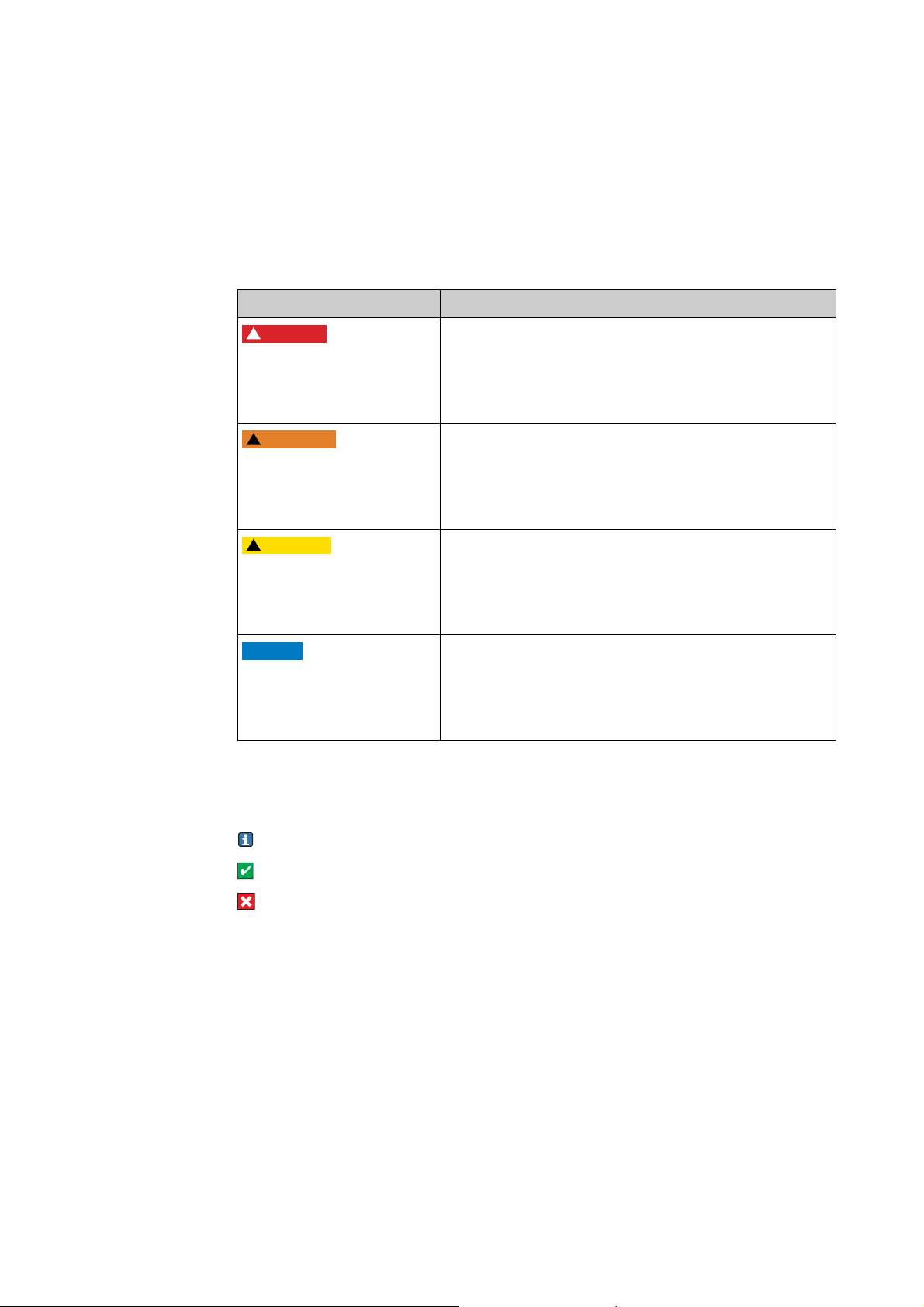
Safety messages
The structure, signal words and safety colors of the signs comply with the specifications of
ANSI Z535.6 ("Product safety information in product manuals, instructions and other
collateral materials").
Safety message structure Meaning
This symbol alerts you to a dangerous situation.
Cause (/consequences)
Consequences if safety
message is not heeded
‣ Corrective action
Cause (/consequences)
Consequences if safety
message is not heeded
‣ Corrective action
Cause (/consequences)
Consequences if safety
message is not heeded
‣ Corrective action
Failure to avoid the situation will result in a fatal or serious
injury.
This symbol alerts you to a dangerous situation.
Failure to avoid the situation can result in a fatal or serious
injury.
This symbol alerts you to a dangerous situation.
Failure to avoid this situation can result in minor or
medium injury.
Cause/situation
Consequences if safety
message is not heeded
‣ Action/note
Symbols
Additional information, tips
Permitted or recommended
Forbidden or not recommended
This symbol alerts you to situations that can result in
damage to property and equipment.
Endress+Hauser
Page 3

Smartec S CLD132/134 PROFIBUS-PA/-DP
Table of contents
1 Basic safety instructions . . . . . . . . . . . . . 4
1.1 Requirements for the personnel . . . . . . . . . . . . . . . 4
1.2 Designated use . . . . . . . . . . . . . . . . . . . . . . . . . . . . . 4
1.3 Workplace safety . . . . . . . . . . . . . . . . . . . . . . . . . . . 4
1.4 Operational safety . . . . . . . . . . . . . . . . . . . . . . . . . . . 4
1.5 Product safety . . . . . . . . . . . . . . . . . . . . . . . . . . . . . . 5
2 Installation . . . . . . . . . . . . . . . . . . . . . . . . 6
2.1 System equipment . . . . . . . . . . . . . . . . . . . . . . . . . . 6
2.2 Post-installation check . . . . . . . . . . . . . . . . . . . . . . . 7
3 Wiring . . . . . . . . . . . . . . . . . . . . . . . . . . . . 8
3.1 Electrical connection . . . . . . . . . . . . . . . . . . . . . . . . 8
3.2 Post-connection check . . . . . . . . . . . . . . . . . . . . . 10
4 Operability. . . . . . . . . . . . . . . . . . . . . . . . 11
4.1 Display and operating elements . . . . . . . . . . . . . 11
4.2 Operation via FieldCare . . . . . . . . . . . . . . . . . . . . 11
5 System integration. . . . . . . . . . . . . . . . . 12
5.1 Block model of PROFIBUS PA/DP . . . . . . . . . . . . 12
5.2 Cyclical data exchange (Data_Exchange) . . . . . 18
5.3 Acyclical data exchange . . . . . . . . . . . . . . . . . . . . 22
6 Commissioning . . . . . . . . . . . . . . . . . . . .30
6.1 Function check . . . . . . . . . . . . . . . . . . . . . . . . . . . 30
6.2 Setting of device address . . . . . . . . . . . . . . . . . . . 30
6.3 Device data and type files . . . . . . . . . . . . . . . . . . . 32
7 Diagnostics and troubleshooting . . . . .35
8 Accessories . . . . . . . . . . . . . . . . . . . . . . .37
9 Technical data . . . . . . . . . . . . . . . . . . . .39
9.1 Output PROFIBUS-PA . . . . . . . . . . . . . . . . . . . . . . 39
9.2 Output PROFIBUS-DP . . . . . . . . . . . . . . . . . . . . . . 39
9.3 Display and user interface . . . . . . . . . . . . . . . . . . 40
9.4 Standards and guidelines . . . . . . . . . . . . . . . . . . . 40
Index. . . . . . . . . . . . . . . . . . . . . . . . . . . . . 42
Endress+Hauser 3
Page 4

Basic safety instructions Smartec S CLD132/134 PROFIBUS-PA/-DP
1 Basic safety instructions
1.1 Requirements for the personnel
‣ Installation, commissioning, operation and maintenance of the measuring system must
only be carried out by trained technical personnel.
‣ The technical personnel must be authorized by the plant operator to carry out the
specified activities.
‣ The electrical connection may only be performed by an electrical technician.
‣ The technical personnel must have read and understood these Operating Instructions
and must follow the instructions they contain.
‣ Measuring point faults may only be rectified by authorized and specially trained
personnel.
Repairs not described in the enclosed Operating Instructions may only be carried out
directly at the manufacturer's or by the service organization.
1.2 Designated use
These Operating Instructions were designed specifically for use with transmitters of the
family Smartec S CLD132/134. They contain specific information for instruments with the
PROFIBUS PA interface (Process Field Bus - Process Automation) or the PROFIBUS DP
interface (Process Field Bus - Decentralized Peripherals).
PROFIBUS is an open field bus standard according to IEC 61158 / IEC 61784. It has been
created specifically for process control purposes and permits connection of several
measuring instruments to a bus line. The transmission method according to IEC 1158-2
guarantees safe signal transmission.
The PROFIBUS PA interface permits operation of the instrument from the PC:
• via FieldCare (Plant Asset Management Tool)
Any other use than the one described here compromises the safety of persons and the entire
measuring system and is not permitted.
The manufacturer is not liable for damage caused by improper or non-designated use.
1.3 Workplace safety
As the user, you are responsible for complying with the following safety conditions:
• Regulations for explosion protection
• Installation instructions
• Local standards and regulations
Electromagnetic compatibility
With regard to electromagnetic compatibility, this device has been tested in accordance with
the applicable European standards for industrial applications.
The electromagnetic compatibility indicated only applies to a device that has been connected
in accordance with the instructions in these Operating Instructions.
1.4 Operational safety
‣ Before commissioning the entire measuring point, make sure all the connections are
correct. Ensure that electrical cables and hose connections are not damaged.
‣ Do not operate damaged products, and safeguard them to ensure that they are not
operated inadvertently. Mark the damaged product as defective.
‣ If faults cannot be rectified, the products must be taken out of service and secured against
unintentional commissioning.
4 Endress+Hauser
Page 5

Smartec S CLD132/134 PROFIBUS-PA/-DP Basic safety instructions
1.5 Product safety
The product is designed to meet state-of-the-art safety requirements, has been tested and
left the factory in a condition in which it is safe to operate. Relevant regulations and
European standards have been observed.
Endress+Hauser 5
Page 6
Installation Smartec S CLD132/134 PROFIBUS-PA/-DP
PROFIBUS PA
PROFIBUS DP
1
2
3
4
5
ENDRESS+HAUSER
SMARTECS
ENDRESS+HAUSER
SMARTECS
ALARM
CAL
E
+
–
6
7
2Installation
2.1 System equipment
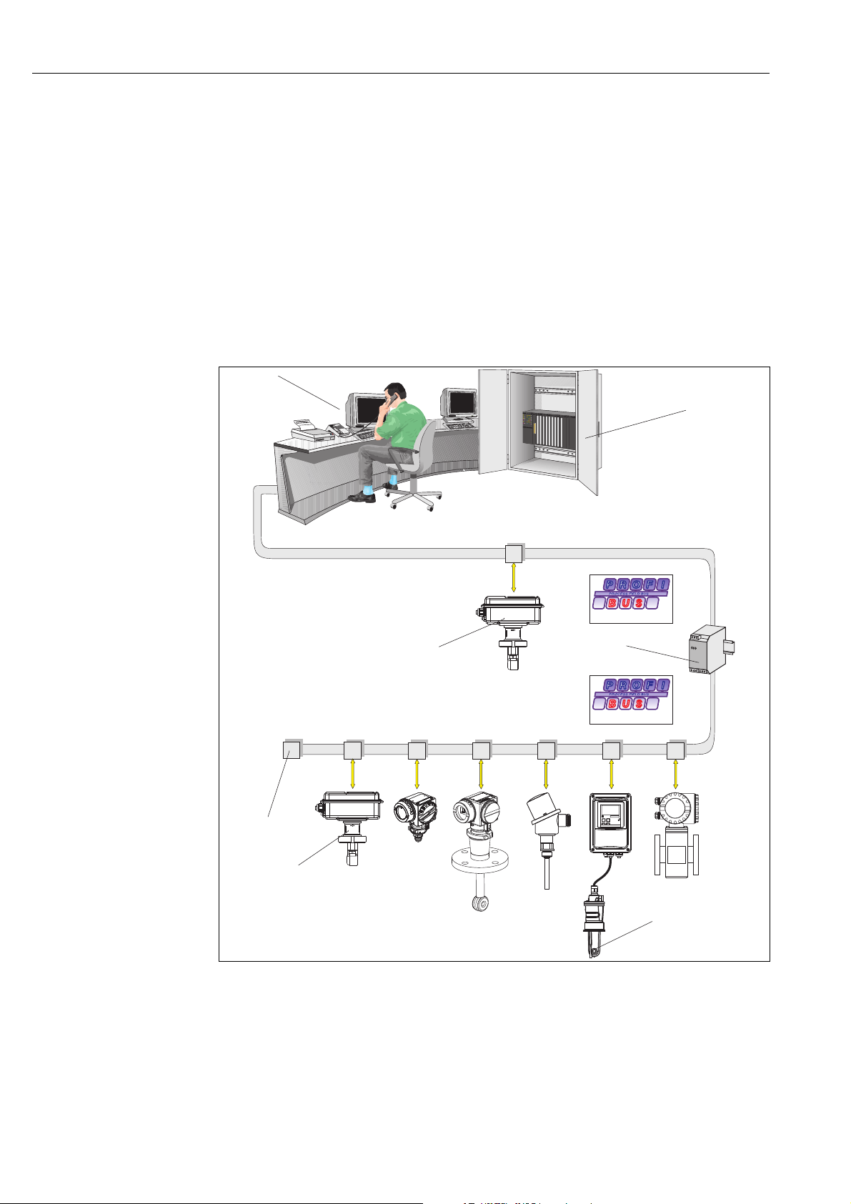
A complete system architecture comprises:
• Transmitter Smartec S CLD132 or CLD134
• Segment coupler (PA only)
• PROFIBUS termination
• Cabling incl. bus distributor
• either
– PC with FieldCare or
– Programmable logic controller (PLC)
Fig. 1: Measuring systems with PROFIBUS interface
1 PC with PROFIBUS interface
2PLC
3 Smartec S CLD132/134 PROFIBUS DP compact version
4Segment coupler
5Termination
6 Smartec S CLD132/134 PROFIBUS PA compact version
7 Smartec S CLD132/134 PROFIBUS PA separate version with CLS52/54
a0005890
6 Endress+Hauser
Page 7

Smartec S CLD132/134 PROFIBUS-PA/-DP Installation
The maximum number of transmitters in a bus segment is determined by their power
consumption, the bus coupler output and the required bus length.
For detailed information on function and connection of a PROFIBUS system, please
refer to Technical Information TI00260F/00/en
2.2 Post-installation check
• After installation, check the transmitter for damage.
• Check whether the transmitter is protected against moisture and direct sunlight (e.g. by
the weather protection cover).
Endress+Hauser 7
Page 8
Wiring Smartec S CLD132/134 PROFIBUS-PA/-DP
WARNING
!
WARNING
!
3 Wiring
Device is energized
Improper connection can cause injury or death.
‣ The electrical connection must only be carried out by a certified electrician.
‣ Technical personnel must have read and understood the instructions in this manual and
must adhere to them.
‣ Prior to beginning any wiring work, make sure voltage is not applied to any of the cables.
3.1 Electrical connection
Proceed as follows to connect the bus cable to the transmitter:
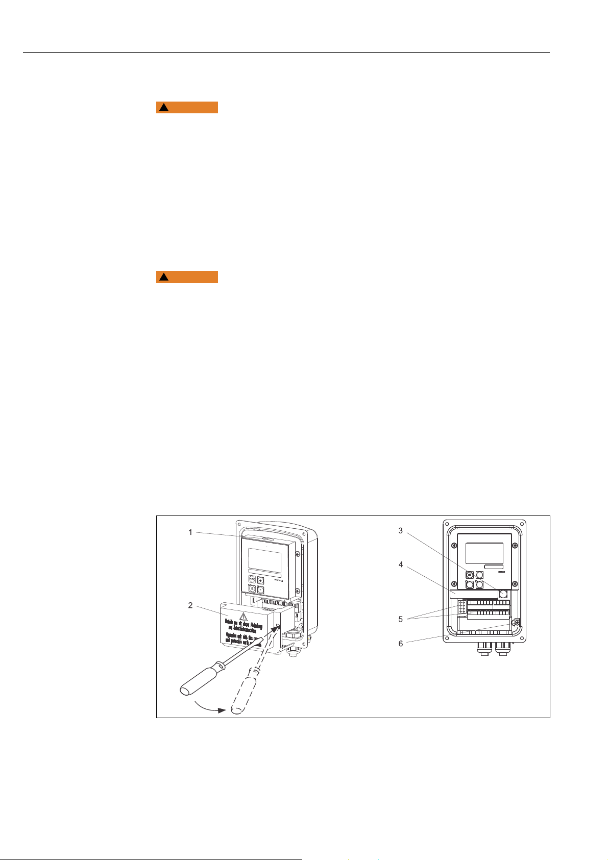
1. Loosen the 4 Phillips screws on the housing cover and remove the cover.
Instrument is energized
Inproper connection can cause injury or death.
‣ Make sure the instrument is disconnected from the power source before you remove the
cover frame.
2. Remove the cover frame from the terminal blocks. To do this, introduce a screwdriver in
the recess (A) according to å 2 and push the tab inward (B).
3. Thread the cables through the open cable glands into the connection compartment.
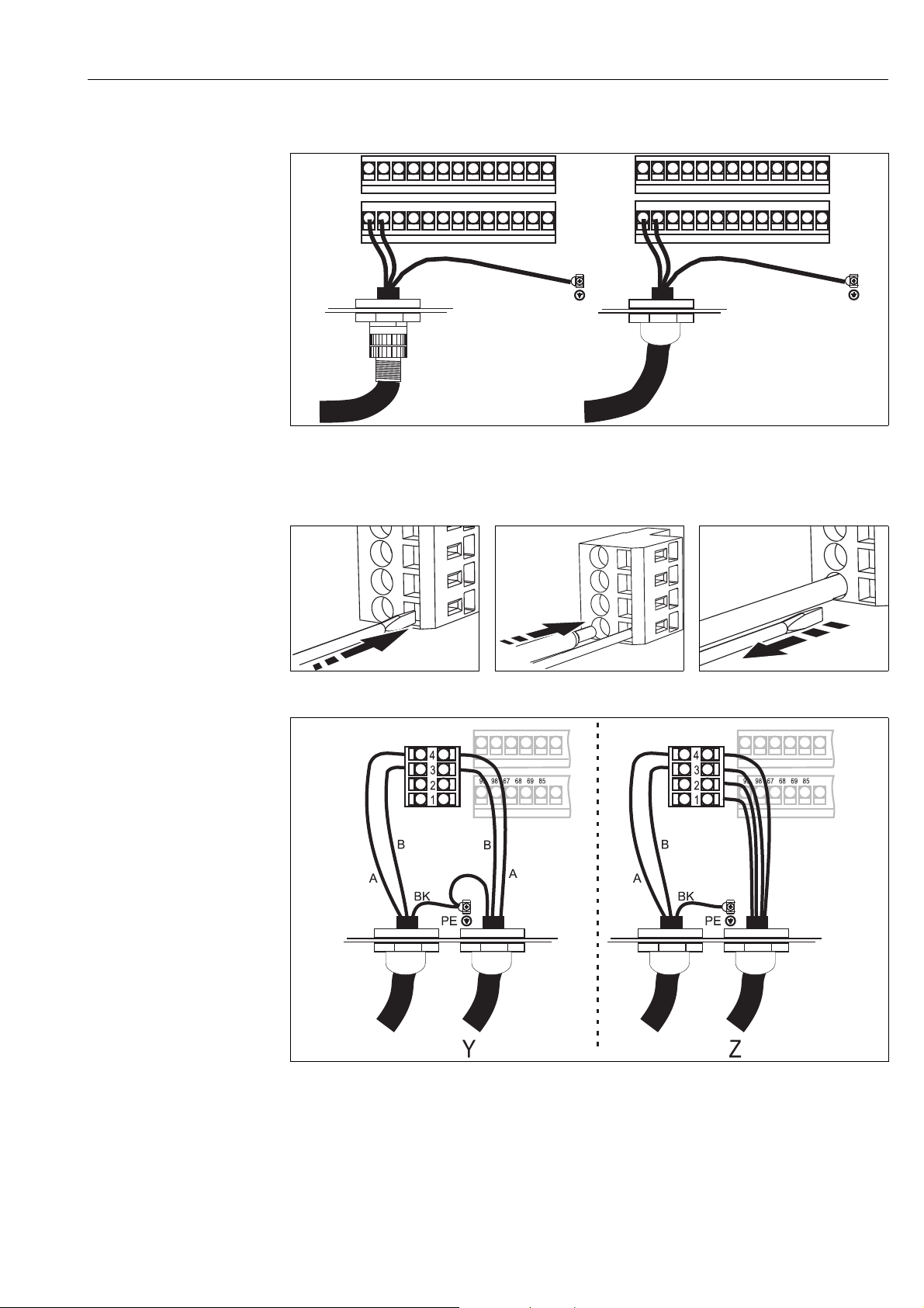
4. Cable connection for PA devices: Connect the cable wires of the bus cable in
accordance with å 3 to the terminal block. Mixing up the polarity of the PA+ and
PA- connections does not have any influence on operation. The bus cable can be
connected to the PA device via the Pg cable gland or an M12 plug.
5. Cable connection for DP devices: Connect the cable wires of the bus cable in
accordance with å 7 to the terminal block.
6. Tighten the cable gland.
7. Close the housing cover.
Fig. 2: Bus cable connection Smartec S PROFIBUS
1 Port for DIL switch
2Cover frame
3Fuse
4 Removable electronics box
5Terminals
6 Housing ground
8 Endress+Hauser
a0005891
Page 9
Smartec S CLD132/134 PROFIBUS-PA/-DP Wiring
99 98 67 68 69 85 86 93 94 81 82
99 98 67 68 69 85 86 93 94 81 82
M12
PE
PE
PA+PA+
PA–
BK
BK
PA–
PA device
a0005892
Fig. 3: PA device electrical connection
DP device
a0012694
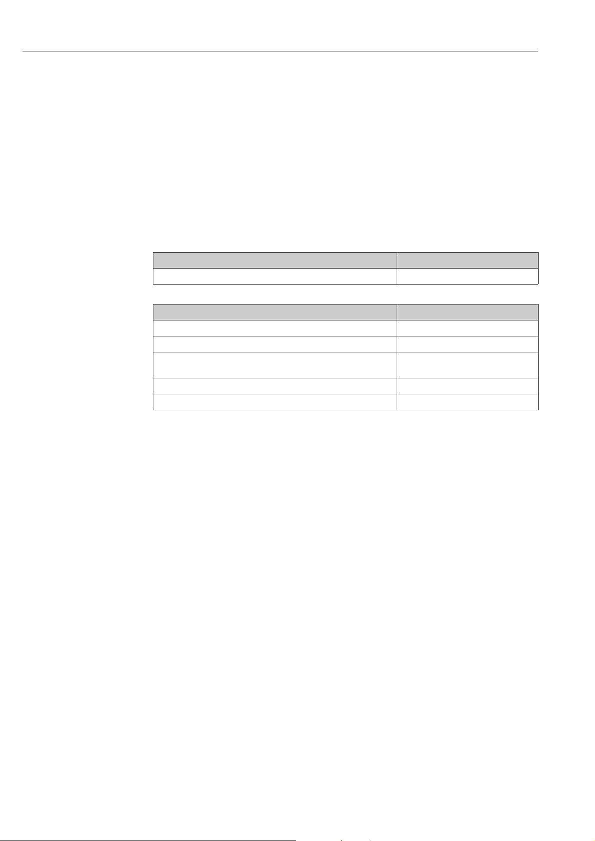
Fig. 4: Insert the screwdriver (opens
Fig. 7: DP device electrical connection
1GND
2 Power supply +5 V for bus termination
3 B (RxD / TxD-P)
4A (RxD / TxD-N)
Y Next PROFIBUS device
Z Bus termination
the terminal)
a0012695
Fig. 5: Insert the cable until the limit
stop
a0012696
Fig. 6: Remove the screwdriver
(closes the terminal)
a0017420
Endress+Hauser 9
Page 10
Wiring Smartec S CLD132/134 PROFIBUS-PA/-DP
The remaining connection (sensor, power supply etc.) are described in the standard
Operating Instructions (BA00207C/07/EN for CLD132, BA00401C/07/EN for CLD134).
Bus termination
The bus terminations for PROFIBUS PA and DP are different.
Each PROFIBUS PA segment must be terminated with a passive bus termination on each
end.
Each PROFIBUS DP segment must be terminated with an active bus termination on each
end.
3.2 Post-connection check
After the electrical connection, carry out the following checks:
Device condition and specifications Notes
Are the transmitter and cables damaged on the outside? Visual inspection
Electrical connection Notes
Are the mounted cables strain relieved?
Cable run without loops and cross-overs?
Are the signal lines correctly connected in accordance with the wiring
diagram?
Are all screw terminals tightened?
Are all cable entries installed, tightened and sealed?
10 Endress+Hauser
Page 11
Smartec S CLD132/134 PROFIBUS-PA/-DP Operability
ENDRESS+HAUSER
SMARTEC S
ALARM
CAL
E
+
–
2000
mS/cm
O213
20 mA
1
4Operability
4.1 Display and operating elements
a0005901
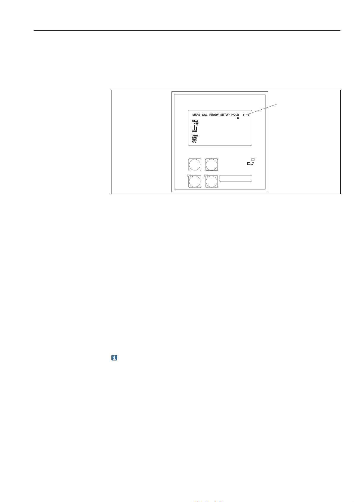
Fig. 8: User interface of Smartec S
1 Display symbol for active communication via PROFIBUS interface
Please refer to the standard Operating Instructions for an explanation of the key assignment
and the other icons and symbols.
4.2 Operation via FieldCare
FieldCare is Endress+Hauser's FDT-based Plant Asset Management Tool. It can configure all
intelligent field devices in your plant and supports you in managing them. By using status
information, it also provides a simple but effective means of checking their health.
• Supports HART and PROFIBUS
• Operates all Endress+Hauser devices
• Integrates third-party devices such as actuators, I/O systems and sensors supporting the
FDT standard
• Ensures full functionality for all devices with DTMs
• Offers generic profile operation for third-party fieldbus devices that do not have a vendor
DTM
For information on FieldCare installation see the operating instructions "Getting started"
BA00027S/04/a4.
Endress+Hauser 11
Page 12
System integration Smartec S CLD132/134 PROFIBUS-PA/-DP
Sensor
Signal processing
Manufacturer specific
parameters
Analyzer Transducer Block 1
Main Meas. Value
Main Process Value
Analog Input Block 1
Main Meas. Value
Main Process Value
Analyzer Transducer Block 2
Temperature Value
Temperature
Analog Input Block 2
Temperature Value
Temperature
OUT VALUE
Value/Status
OUT VALUE
Value/Status
PROFIBUS Master Class 1 (cyclical data)
MRS
Local operation
Physical Block
Funktionsgruppe
ALPHA-TABELLE
Eingabeder Anzahl der
Tabellenstützpunkte
1... 10
1
Auswahlder
Tabellen
1... 4
(>1nur bei MBU)
1
Auswahlder
Tabellenoption
edit
lesen
T2
Multiplikationsfaktor
fürden Konzentrationswert
einerUser-Tabelle
(nurbei MBU)
0,5... 1,5
1
K2
T1
Auswahldes
Tabellenwertepaares
1... Anzahl aus R3
fertg
1
T4
Eingabedes
Temperaturwertes
(x-Wert)
–35,0... 250,0 °C
0,0°C
T5
T
T3
Funktionsgruppe
KONZENTRATION
K
Auswahlder aktiven
Konzentrationstabelle
;H SO ;
HPO ; HNO
User ... 4
NaOH
1
24
34 3
K1
Auswahlder
Tabellen
1... 4
(>1nur bei MBU)
1
K3
Auswahlder
Tabellenoption
edit
lesen
K4
Eingabeder Anzahl der
Tabellenstützpunkte
1... 16
1
K5
Funktionsgruppe
SERVICE
S
Auswahlder
Sprache
;GER
ITA;FRA
ESP;NEL
ENG
S1
HOLD-Konfiguration
Kein= kein HOLD
Setup= bei Parametrieren
CAL= bei Kalibrieren
S+C= bei Parametrieren
undKalibrieren
S4
Eingabedes
Festwertes
(nurfall Fest)
0... 100 %
von20 bzw. 16 mA
0
Auswahldes
HOLD-Effektes
Fest= fester Wert
Letzt= letzter Wert
S3S2
ManuellerHOLD
ein
aus
S5
5 System integration
5.1 Block model of PROFIBUS PA/DP
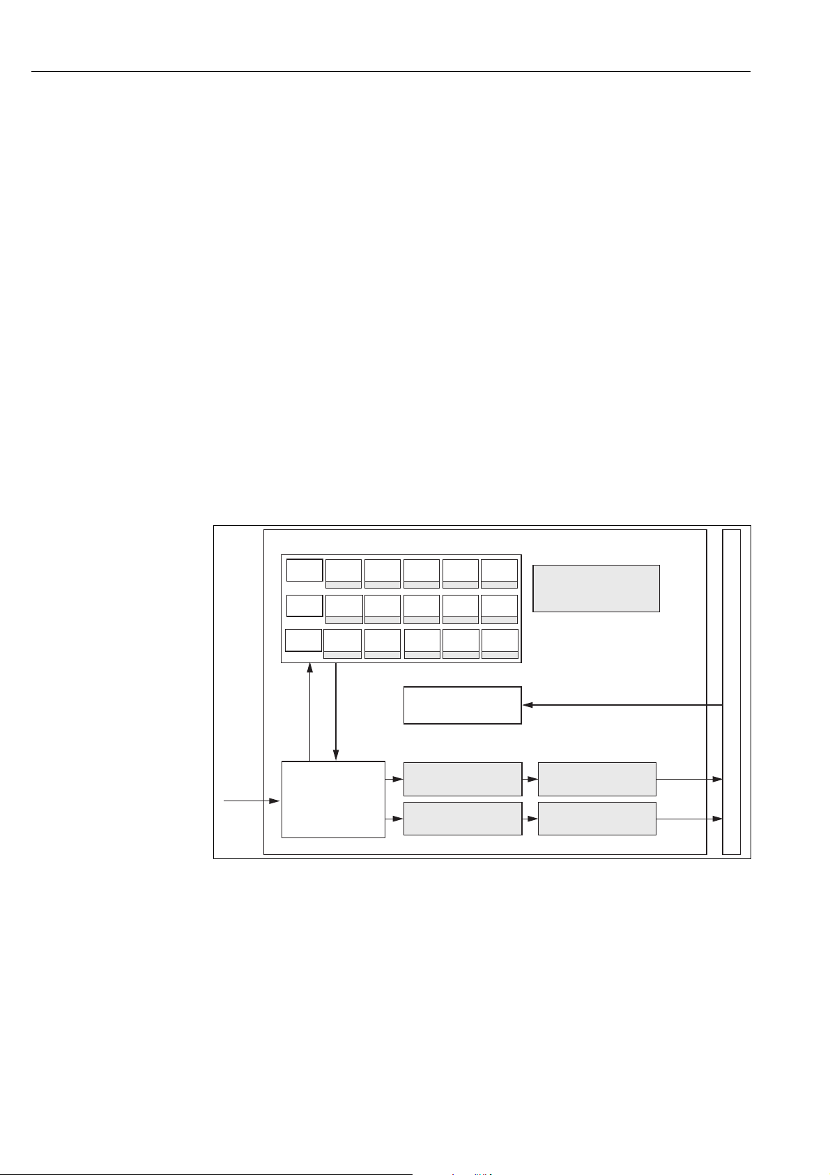
In the PROFIBUS configuration, all the device parameters are categorized according to their
functional properties and tasks and are generally assigned to three different blocks. A block
may be regarded as a container in which parameters and the associated functionalities are
contained.
A PROFIBUS device has the following block types (see å 9):
• A Physical Block (device block)
The Physical Block contains all device-specific features of the unit.
• One or more Transducer Blocks
The Transducer Block contains all the measuring and device-specific parameters of the
device. The measuring principles (e.g. conductivity, temperature) are depicted in the
Transducer Blocks in accordance with the PROFIBUS Profile 3.0 Specification.
• One or more function blocks
A function block contains the automation functions of the device. The transmitter contains
Analog Input blocks by means of which the measured values can be scaled and examined
for limit value overshoot.
A number of automation-related tasks can be implemented with these blocks. In addition to
these blocks, a transmitter can have any number of additional blocks, for example several
Analog Input function blocks if the transmitter can process more than one process variable.
Fig. 9: Block model of Smartec S (grey = profile blocks)
a0005920-en
12 Endress+Hauser
Page 13

Smartec S CLD132/134 PROFIBUS-PA/-DP System integration
Physical Block (device block)
A Physical Block contains all the data that uniquely identify and characterize the
transmitter. It is an electronic version of a nameplate on the transmitter. Parameters of the
Physical Block are, for example, device type, device name, manufacturer's identification,
serial number, etc.
A further task of the Physical Block is the management of general parameters and functions
that influence the execution of the other blocks in the transmitter. The Physical Block is thus
the central unit that also checks the device status and thereby influences or controls the
operability of the other blocks and thus also of the device.
Write protection
• On-site hardware write protection
By pressing the "Enter" and the "Plus" keys simultaneously, you can lock the device for onsite configuration operations.
Use the "Cal" and "Minus" keys to unlock the device. You can find more information in the
standard Operating Instructions under "Locking/Unlocking keypad".
• Hardware write protection via PROFIBUS
The HW_WRITE_PROTECTION parameter indicates the status of the hardware write
protection. The following statuses are possible:
1: Hardware write protection enabled, device data cannot be overwritten.
0: Hardware write protection disabled, device data can be overwritten.
• Software write protection
You can also set software write protection to prevent all parameters from being acyclically
overwritten. You can do so by making an entry in the WRITE_LOCKING parameter. The
following entries are permitted:
2457: Device data can be overwritten (factory setting).
0: Device data cannot be overwritten.
Parameter LOCAL_OP_ENABLE
You can use the LOCAL_OP_ENABLE parameter to permit or lock local operation at the
device. The following values are possible:
• 0: Deactivated.
Local operation is locked. You can only change this status via the bus.
The code 9998 is displayed in the local operation. The transmitter behaves just as with
hardware write protection via the keyboard (see above).
• 1: Activated.
Local operation is active. However, commands from the master have a higher priority than
local commands.
Local operation is automatically activated if communication should fail for longer than
30 seconds.
If communication fails when local operation is locked, the device will immediately
return to the locked status as soon as communication is functioning again.
Parameter PB_TAG_DESC
You can set the client-specific device number (tag number) via:
• local operation in menu field I2 (INTERFACE function group) or via
• PROFIBUS parameter TAG_DESC of the Physical Block.
If you change the tag number via one of the two options, the change can also be seen
immediately at the other position.
Endress+Hauser 13
Page 14
System integration Smartec S CLD132/134 PROFIBUS-PA/-DP
HI_HI_ALM
HI_ALM
LO_ALM
LO_LO_ALM
Transducer
Block
ACTUAL_MODE
1
1
1
0
PV
OUT
0
PV_SCALE
PV_SCALE_MIN
PV_SCALE_MAX
OUT_SCALE
OUT_SCALE_UNIT
OUT_SCALE_MIN
OUT_SCALE_MAX
HI_HI_LIM
HI_LIM
LO_LIM
LO_LO_LIM
ALARM_HYS
HI_HI_ALM
HI_ALM
LO_ALM
LO_LO_ALM
SIMULATION
VALUE
STATUS
ON_OFF
LIN_TYPE
CHANNEL
NORMAL_MODE
PERMITTED_MODE
ACTUAL_MODE
FSAFE_TYPE
FSAFE_VALUE
MODE_BLK
MAN
MAN
PV_TIME
1
t
FAIL
SAFE
OUT
MODE/
STATUS
AUTO
O/S
Parameter FACTORY_RESET
You can reset the following data via the FACTORY_RESET parameter:
1 all data to PNO default values
2506 transmitter warm start
2712 bus address
32768 calibration data
32769 setting data
Via local operation you can either reset all data to the factory settings or delete the sensor
data in menu field S10 (SERVICE function group).
Parameter IDENT_NUMBER_SELECTOR
You can use the IDENT_NUMBER_SELECTOR parameter to switch the transmitter between
three operating modes, each of which has different functionality in relation to the cyclic
data:
IDENT_NUMBER_SELECTOR Functionality
0 Cyclic communication only possible with Profile GSD. Only standard
diagnosis in cyclic data.
1 (default) Full functionality with Profile 3.0 and extended diagnosis in cyclic
data. The manufacturer-specific GSD is required.
2 Downwards compatible Profile 2.0 functionality without diagnosis in
cyclic data. The manufacturer-specific Profile 2.0 GSD is required.
See also table "Device Master Files for Smartec S".
Analog Input Block (function block)
In the Analog Input function block, the process variables (conductivity and temperature) of
the Transducer Block are prepared, in terms of instrumentation and control, for the
subsequent automation functions (e.g. scaling, limit value processing). There are two
Analog Input function blocks available for the Smartec S PROFIBUS transmitter.
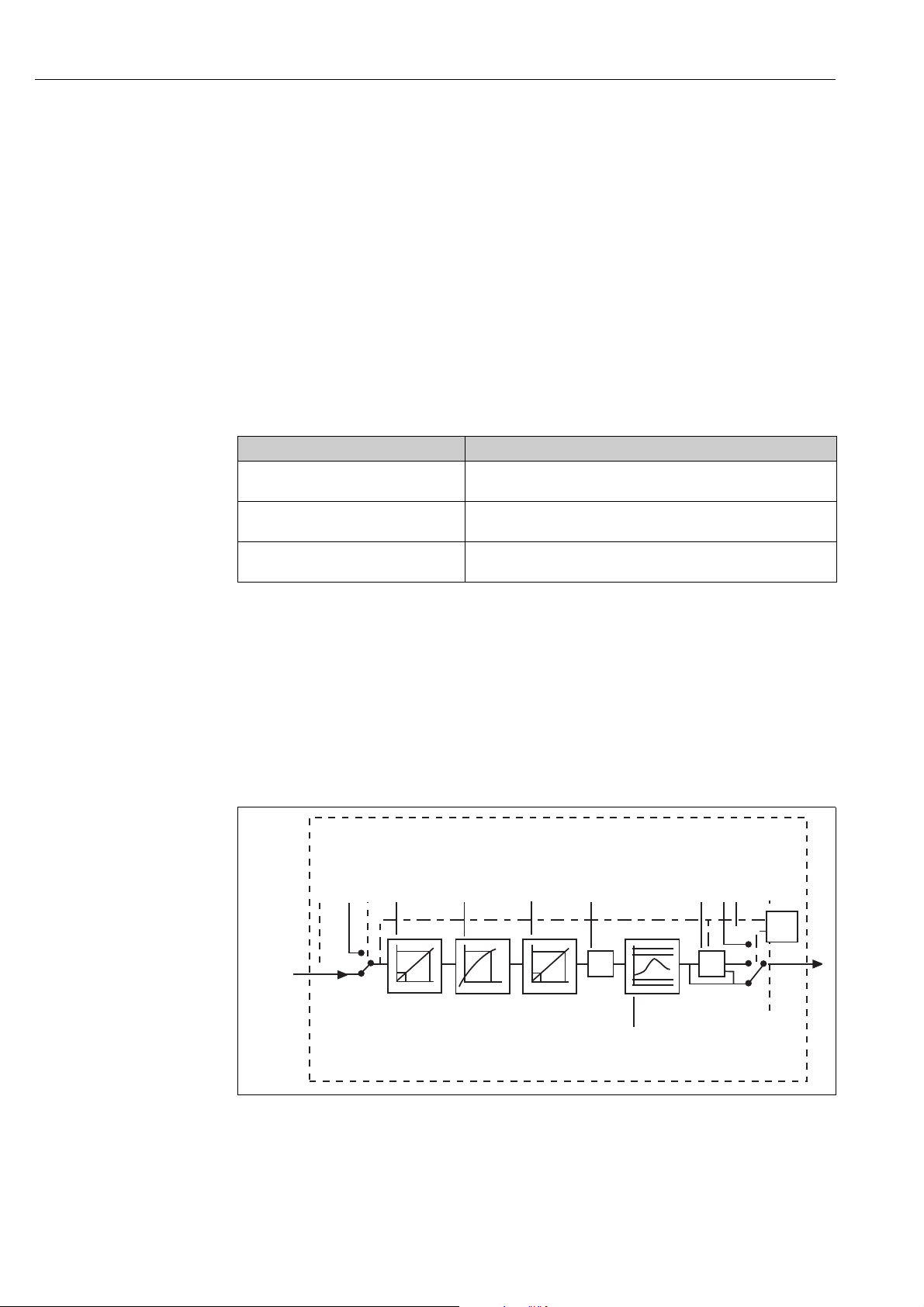
Signal processing
The diagram shows a schematic of the internal structure of an Analog Input function block:
Fig. 10: Schematic internal structure of an Analog Input function block
The Analog Input function block receives its input value from the Analyzer Transducer Block.
The input values are permanently assigned to each Analog Input function block:
• Main measured value (Main Process Value) – Analog Input function block 1 (AI 1)
• Measured temperature value (temperature) – Analog Input function block 2 (AI 2)
14 Endress+Hauser
a0005921
Page 15

Smartec S CLD132/134 PROFIBUS-PA/-DP System integration
SIMULATE
In the SIMULATE parameter group you can replace the input value with a simulation value
and activate simulation. By specifying the status and the simulation value, you can test the
reaction of the automation system.
PV_FTIME
In the PV_FTIME parameter you can dampen the converted input value (primary value = PV)
by specifying a filter time. If a time of 0 seconds is specified, the input value is not dampened.
MODE_BLK
The MODE_BLK parameter group is used to select the operating mode of the Analog Input
function block. By selecting the MAN (manual) operating mode, you can directly specify the
OUT output value and the OUT status.
The most important functions and parameters of the Analog Input Block are listed below.
Selecting the operating mode
The operating mode is set by means of the MODE_BLK parameter group. The Analog Input
function block supports the following operating modes:
• AUTO (automatic mode)
•MAN (manual mode)
• O/S (out of service)
Selecting the units
The system unit for one of the measured values can be changed in the Analog Input Block.
The way of changing the unit is to use the PV_SCALE and OUT_SCALE parameters (see
"Rescaling the input value").
OUT
The OUT output value is compared to warning limits and alarm limits (e.g. HI_LIM,
LO_LIM), which can be entered via diverse parameters. If one of these limit values is
violated, a limit value process alarm (e.g. HI_ALM, LO_ALM) is triggered.
Endress+Hauser 15
Page 16

System integration Smartec S CLD132/134 PROFIBUS-PA/-DP
OUT status
The status of the Analog Input function block and the validity of the OUT output value are
relayed to the downstream function blocks by means of the status of the OUT parameter
group. The following status values can be displayed:
• GOOD_NON_CASCADE
The OUT output value is valid and can be used for further processing.
•UNCERTAIN
The OUT output value can only be used for further processing to a limited extent.
• BAD
The OUT output value is invalid. Occurs when the Analog Input function block is switched
to the O/S operating mode (Out of Service) or in the event of a serious error (see status
codes and system or process-specific error messages in the Operating Instructions
BA207C/07/en or BA401C/07/en).
In addition to the device-internal error messages, other device functions have an influence
on the status of the OUT value:
• Automatic hold
If "Hold" is switched on, the Out Status is set to BAD not specific (0x00).
• Calibration
During calibration, the OUT Status is set to the UNCERTAIN sensor calibration value
(0x64) (even when hold is switched on).
Simulation of input/output
You can simulate the input and output of the function block by means of various parameters
of the Analog Input function block:
1. Simulating the input of the Analog Input function block:
The SIMULATION parameter group can be used to specify the input value (measured
value and status). Since the simulation value runs through the entire function block, you
can check all the parameter settings of the block.
2. Simulating the output of the Analog Input function block:
Set the operating mode in the MODE_BLK parameter group to MAN and directly specify
the desired output value in the OUT parameter.
Measured value simulation in local operation
In the case of measured value simulation in local operation, the status UNCERTAIN –
simulated value is relayed to the function blocks. This triggers the failsafe mechanism in the
AI blocks.
Error response (FSAFE_TYPE)
If an input or simulation value has the status BAD, the Analog Input function block uses the
error response defined in the FSAFE_TYPE parameter. The FSAFE_TYPE parameter offers
the following error response options:
•FSAFE_VALUE
The value specified in the FSAFE_VALUE parameter is used for further processing.
• LAST_GOOD_VALUE
The last good value is used for further processing.
•WRONG_VALUE
The current value is used for further processing, despite the BAD status.The default is the
setting (FSAFE_VALUE) with value “0”.
Error response is also activated if the Analog Input function block is set to the “OUT OF
SERVICE” operating mode.
16 Endress+Hauser
Page 17
Smartec S CLD132/134 PROFIBUS-PA/-DP System integration
Transducer
Block
25 °C
-10
150
°C
77 °F
14
°F
302
OUT
PV_SCALE OUT_SCALE
0
0
100
100
%
tempe-
rature
Analog Input Function Block
–10 ... 150 °C
ENDRESS+HAUSER
SMARTECS
ENDRESS+HAUSER
SMARTECS
ALARM
CAL
E
+
–
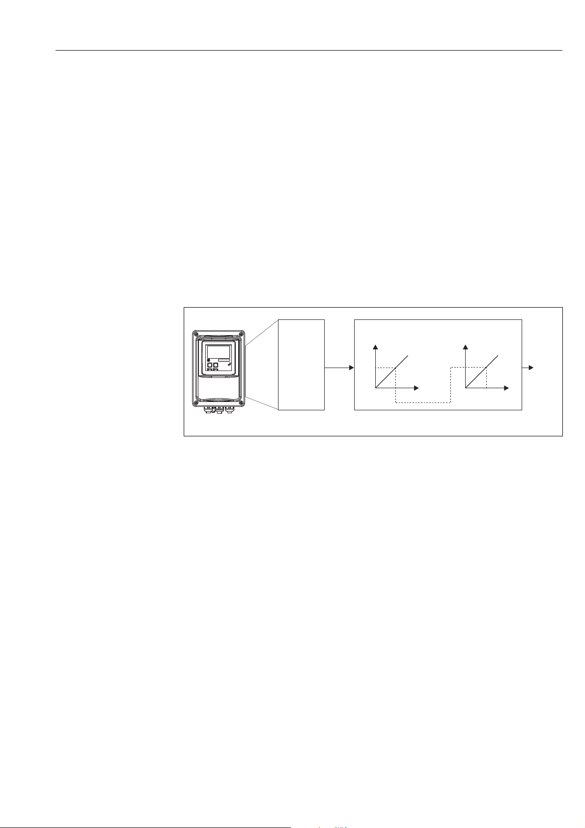
Rescaling the input value
In the Analog Input function block, the input value or input range can be scaled in
accordance with the automation requirements.
Example:
• The system unit in the Transducer Block is °C.
• The measuring range of the device is –10 to 150 °C.
• The output range to the automation system should be 14 °F to 302 °F.
• The measured value from the Transducer Block (input value) is rescaled linearly via the
input scaling PV_SCALE to the desired output range OUT_SCALE.
• Parameter group PV_SCALE
PV_SCALE_MIN (V1H0) –10
PV_SCALE_MAX (V1H1) 150
• Parameter group OUT_SCALE
OUT_SCALE_MIN (V1H3) 14
OUT_SCALE_MAX (V1H4) 302
OUT_UNIT (V1H5) [F]
The result is that with an input value of 25 °C, for example, a value of 77 °F is output via the
OUT parameter ( å 11).
a0005922-en
Fig. 11: Scaling the input value for the Analog Input function block
Limit values
You can set two warning limits and two alarm limits for monitoring your process. The status
of the measured value and the parameters of the limit-value alarms are indicative of the
measured value's relative position. You also have the option of defining an alarm hysteresis
in order to avoid frequent changes of the limit-value flags and frequent enabling/disabling
of alarms.
The limit values are based on the OUT output value. If the OUT output value exceeds or
undershoots the defined limit values, the automation system is alarmed via the limit value
process alarms (see below).
The following limit values can be defined:
– HI_LIM, HI_HI_LIM
– LO_LIM, LO_LO_LIM
Alarm detection and processing
Limit value process alarms are generated by the Analog Input function block. The status of
the limit value process alarms is communicated to the automation system by means of the
following parameters:
– HI_ALM, HI_HI_ALM
– LO_ALM, LO_LO_ALM
Endress+Hauser 17
Page 18
System integration Smartec S CLD132/134 PROFIBUS-PA/-DP
5.2 Cyclical data exchange (Data_Exchange)
The Smartec S provides the following modules as input data (data from transmitter to PLC)
for the cyclic data telegram:
Input data (data from transmitter to PLC)
• Main Process Value
This byte transfers the main measured value.
• Temperature
This byte transfers the temperature.
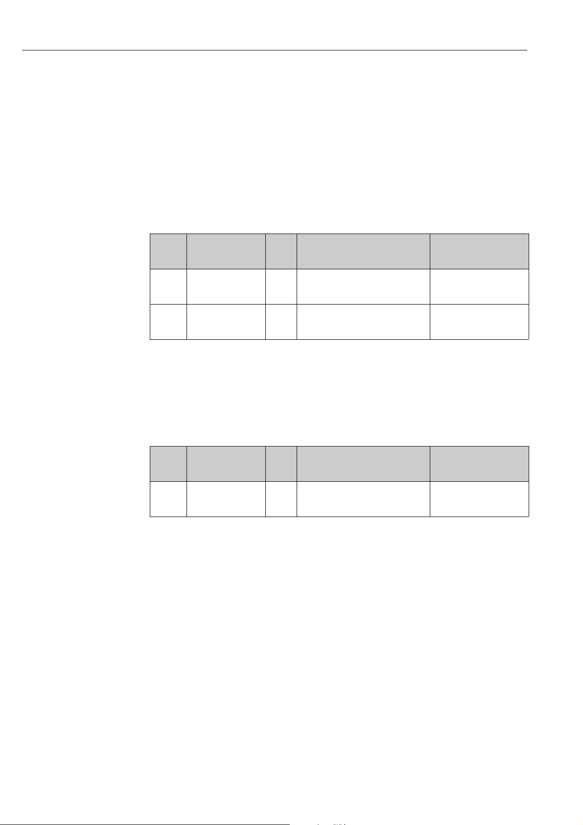
Structure of the input data (Smartec S to PLC)
The input data is transferred from the transmitter in the following structure:
Index
Input
Data
0...4 Analog Input Block 1
5...9 Analog Input Block 2
Data Access Data format Configuration data
0x42, 0x84, 0x08, 0x05 or
0x42, 0x84, 0x81, 0x81 or
0x94
0x42, 0x84, 0x08, 0x05 or
0x42, 0x84, 0x81, 0x81 or
0x94
"Main Process Value"
"Temperature"
read Measured value (32-bit floating point
number; IEEE-754)
Status byte (0x80) = Ok
read Measured value (32-bit floating point
number; IEEE-754)
Status byte (0x80) = Ok
Outut data (data from PLC to transmitter)
• MRS (Measuring Range Switch)
This byte transfers the external hold and the parameter set switch from the PLC to the
transmitter.
Structure of the output data (PLC to Smartec S)
The output data of the PLC for device control have the following structure:
Index
Input
Data
0MRS writeByte
Data Access Data format Configuration data
0x42, 0x84, 0x08, 0x05 or
Status byte (0x80) = Ok
0x42, 0x84, 0x81, 0x81 or
0x94
18 Endress+Hauser
Page 19
Smartec S CLD132/134 PROFIBUS-PA/-DP System integration
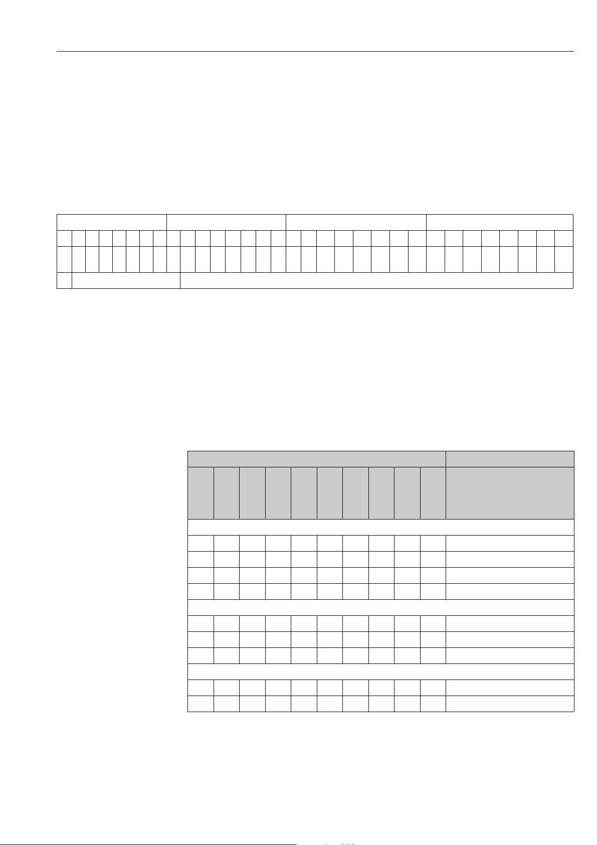
PROFIBUS processes data in hexadecimal code and converts them into 4 bytes (each 8 bits,
4x8=32 bits).
In accordance with IEEE 754, a number has three components:
•Sign (S)
The sign requires exactly 1 bit and has the values 0 (+) or 1(-).
Bit 7 of the 1st byte of a 32-bit floating-point number defines the sign.
• Exponent
The exponent is composed of bits 6 to 0 of the 1st byte plus bit 7 of the 2nd byte (= 8 bits).
• Mantissa
The remaining 23 bits are used for the mantissa.
Byte 1 Byte 2 Byte 3 Byte 4
7654321076543210765 4 3 21076543210
-
-
-
-
-
-
-
-
-
-
-
-
-
-
-
-
-
-
-
-
-
-
VZ27262524232221202
-
2
2
1
2
2
4
3
2
2
6
5
2
2
8
7
2
2
10
9
2
2
12
11
2
2
14
13
2
2
16
15
SExponent Mantissa
2
17
19
18
21
20
2
2
2
2
2
2
23
22
Formula (IEEE 754): Value = (-1)VZ * 2
(exponent - 127)
* (1 + Mantissa)
Example: 40 F0 00 00 = 0 10000001 1110000 00000000 00000000
(hexadecimal) Byte 1 Byte 2 Byte 3 Byte 4
0
Value =
(-1)
=
1 * 22 * (1 + 0.5 + 0.25 + 0.125)
=
1 * 4 * 1.875
=
7.5
* 2
(129 - 127)
* (1 + 2-1 + 2-2 + 2-3)
Explanation of measuring range switch (MRS)
MRS Function
E2
E1
reserved
reserved
reserved
reserved
reserved
number of binary inputs = 2; E1 and E2 active
- - - - - 0 0 0 0x00 MRS 1
- - - - - 0 1 1 0x01 MRS 2
- - - - - 1 0 2 0x02 MRS 3
- - - - - 1 1 3 0x03 MRS 4
number of binary inputs = 1; E1 and E2 active
- - - - - 0 0 0 0x00 MRS 1
- - - - - - 1 1 0x01 Hold on
- - - - - 1 0 2 0x02 MRS 2
number of binary inputs = 0; E1 active
- - - - - - 0 - 0x00 Hold off
- - - - - 1 1 0x01 Hold on
decimal
hexadecimal
Endress+Hauser 19
Page 20
System integration Smartec S CLD132/134 PROFIBUS-PA/-DP
Customizing the cyclic data telegram
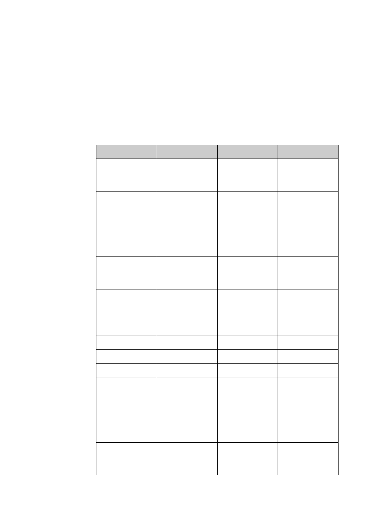
You can customize the cyclic telegram to better meet the requirements of a process. The
tables above represent the maximum contents of the cyclic data telegram.
If you do not want to use all output variables of the transmitter, you can use the device
configuration (CHK_CFG) to eliminate individual data blocks from the cyclic telegram via the
PLC software. Shortening the telegram improves the data throughput rate of a PROFIBUS
system. You should only keep those blocks active which you process further in the system.
You can do this by means of a ”negative” selection in the configuration tool.
To achieve the correct structure of the cyclic data telegram, the PROFIBUS master must send
the identification FREE_PLACE (00h) for the non-active blocks.
Status codes for the OUT parameter of the Analog Input block
Status code Device status Meaning Limits
0x00
0x01
0x02
0x03
0x04
0x05
0x06
0x07
0x0C
0x0D
0x0E
0x0F
0x10
0x11
0x12
0x13
0x1F BAD out of service CONST
0x40
0x41
0x42
0x43
0x47 UNCERTAIN last usable value CONST
BAD non-specific OK
LOW_LIM
HIGH_LIM
CONST
BAD configuration error OK
LOW_LIM
HIGH_LIM
CONST
BAD device failure OK
LOW_LIM
HIGH_LIM
CONST
BAD sensor failure OK
LOW_LIM
HIGH_LIM
CONST
UNCERTAIN non-specific OK
LOW_LIM
HIGH_LIM
CONST
0x4B UNCERTAIN substitute set CONST
0x4F UNCERTAIN initial value CONST
0x50
0x51
0x52
0x53
0x5C
0x5D
0x5E
0x5F
0x60
0x61
0x62
0x63
UNCERTAIN sensor conversion not
accurate
UNCERTAIN configuration error OK
UNCERTAIN simulated value OK
OK
LOW_LIM
HIGH_LIM
CONST
LOW_LIM
HIGH_LIM
CONST
LOW_LIM
HIGH_LIM
CONST
20 Endress+Hauser
Page 21

Smartec S CLD132/134 PROFIBUS-PA/-DP System integration
Status code Device status Meaning Limits
0x64
0x65
0x66
0x67
0x80
0x83
0x84
0x85
0x86
0x87
0x89
0x8A
0x8D
0x8E
UNCERTAIN sensor calibration OK
LOW_LIM
HIGH_LIM
CONST
GOOD ok OK
CONST
GOOD update event OK
LOW_LIM
HIGH_LIM
CONST
GOOD active advisory alarm LOW_LIM
HIGH_LIM
GOOD active critical alarm LOW_LIM
HIGH_LIM
Endress+Hauser 21
Page 22

System integration Smartec S CLD132/134 PROFIBUS-PA/-DP
5.3 Acyclical data exchange
Acyclic data exchange is used to transfer parameters during commissioning, during
maintenance or to display other measured variables that are not contained in the cyclic user
data traffic.
Generally, a distinction is made between Class 1 and Class 2 master connections. Depending
on the implementation of the transmitter, it is possible to simultaneously establish several
Class 2 connections.
• Two Class 2 masters are permitted with Smartec S. This means that two Class 2 masters
can access the transmitter at the same time. However, you must make certain that they do
not both attempt to write to the same data. Otherwise the data consistency can no longer
be guaranteed.
• When a Class 2 master reads parameters, it sends a request telegram to the transmitter
specifying the device address, the slot/index and the expected record length. The
transmitter answers with the requested record if the record exists and has the correct
length (byte).
• When a Class 2 master writes parameters, it transmits the address of the transmitter, the
slot and index, length information (byte) and the record. The transmitter acknowledges
this write job after completion.
22 Endress+Hauser
Page 23
Smartec S CLD132/134 PROFIBUS-PA/-DP System integration
Slot/index tables
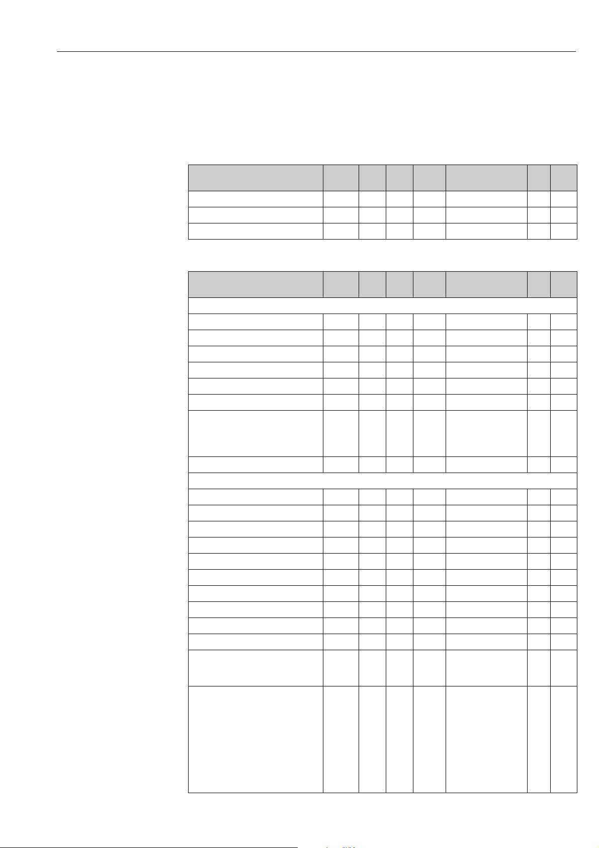
The device parameters are listed in the following tables. You can access these parameters by
means of the slot and index number.
Each individual block comprises standard parameters, block parameters and manufacturerspecific parameters to an extent.
Device management
Parameter E+H
Matrix
DIR_OBJECT HEADER 1 0 12 Array of unsigned16 r Cst.
COMP_LIST_DIR_ENTRIES 1 1 32 Array of unsigned16 r Cst.
COMP_DIR_ENTRIES_CONTINUES 1 2 12 Array of unsigned16 r Cst.
Slot Index Size
(bytes)
Type Acc. Store
Physical Block
Parameter E+H
Matrix
Standard parameter
BLOCK_OBJECT 1 160 20 DS-32* r C
ST_REV 1 161 2 Unsigned16 r N
TAG_DESC VAH0 1 162 32 Octetstring r, w S
STRATEGY 1 163 2 Unsigned16 r, w S
ALERT_KEY 1 164 1 Unsigned8 r, w S
TARGET_MODE 1 165 1 Unsigned8 r, w S
MODE_BLK
Actual
Permitted
Normal
ALARM_SUM 1 167 8 DS-42* r D
Blockparameter
SOFTWARE_REVISION 1 168 16 Visible string r Cst
HARDWARE_REVISION 1 169 16 Visible string r Cst
DEVICE_MAN_ID 1 170 2 Unsigned16 r Cst
DEVICE_ID 1 171 16 Visible string r Cst
DEVICE_SER_NUM 1 172 16 Visible string r Cst
DIAGNOSIS 1 173 4 Octetstring r D
DIAGNOSIS_EXTENSION 1 174 6 Octetstring r D
DIAGNOSIS_MASK 1 175 4 Octetstring r Cst
DIAGNOSIS_MASK_EXTENSION 1 176 6 Octetstring r Cst
DEVICE_CERTIFICATION 1 177 32 Visible string r N
WRITE_LOCKING 1 178 2 Unsigned16
FACTORY_RESET 1 179 2 Unsigned16
Slot Index Size
(bytes)
1 166 3 DS-37*
Type Acc. Store
Unsigned8
Unsigned8
Unsigned8
0: acyclic refused
2457: writeable
0x8000:
reset calibration data
0x8001:
reset set data
0x0001:
PNO defaults
all data
2506: warm start
2712: reset bus adr.
r
N
Cst
Cst
r, w N
r, w S
Endress+Hauser 23
Page 24

System integration Smartec S CLD132/134 PROFIBUS-PA/-DP
Parameter E+H
Matrix
DESCRIPTOR 1 180 32 Octetstring r, w S
DEVICE_MESSAGE 1 181 32 Octetstring r, w S
DEVICE_INSTALL_DATE 1 182 16 Octetstring r, w S
LOCAL_OP_ENABLE 1 183 1 Unsigned8
IDENT_NUMBER_SELECTOR 1 184 1 Unsigned8
HW_WRITE_PROTECTION 1 185 1 Unsigned8
DEVICE_CONFIGURATION 1 196 32 Visible string r N
INIT_STATE 1 197 1 Unsigned8
DEVICE_STATE 1 198 1 Unsigned8
GLOBAL_STATUS 1 199 2 Unsigned16 r D
Gap 1 200 -
E+H-Parameter
ACTUAL_ERROR VAH2 1 208 2 Unsigned16 r D
LAST_ERROR VAH3 1 209 2 Unsigned16 r D
UPDOWN_FEATURES_SUPP 1 210 1 Octetstring r C
DEVICE_BUS_ADDRESS VAH1 1 213 1 Signed8 r N
SET_UNIT_TO_BUS VAH9 1 214 1 Unsigned8
CLEAR_LAST_ERROR VAH4 1 215 1 Unsigned8
Slot Index Size
(bytes)
207
Type Acc. Store
r, w N
0: disabled
1: enabled
r, w S
0: profile specific
1: manufacturer
specific P 3.0
2: manufacturer
specific P2.0
rD
0: unprotected
1: protected
r, w S
1: status before reset
2: run
5: maintenance
r, w D
2: run
5: maintenance
r, w D
0: off
1: confirm
r, w D
0: off
1: confirm
24 Endress+Hauser
Page 25
Smartec S CLD132/134 PROFIBUS-PA/-DP System integration
Analyzer Transducer Block
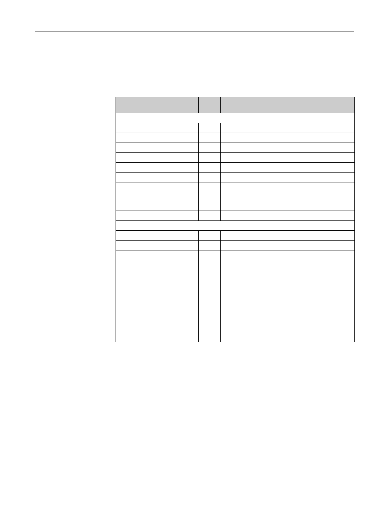
There are two Analyzer Transducer Blocks in the SmarTec S. These are distributed to slots 1
and 2 in the following order:
1. Main measured value (Main Process Value)
2. Measured temperature value (Temperature)
Parameter E+H
Matrix
Standard parameter
BLOCK_OBJECT 1 - 2 100 20 DS-32* r C
ST_REV 1 - 2 101 2 Unsigned16 r N
TAG_DESC 1 - 2 102 32 Octetstring r, w S
STRATEGY 1 - 2 103 2 Unsigned16 r, w S
ALERT_KEY 1 - 2 104 1 Unsigned8 r, w S
TARGET_MODE 1 - 2 105 1 Unsigned8 r, w S
MODE_BLK
Actual
Permitted
Normal
ALARM_SUM 1 - 2 107 8 DS-42* r D
Block parameter
COMPONENT_NAME 1 - 2 108 32 Octetstring r, w S
PV 1 - 2 109 12 DS-60* r D
PV_UNIT 1 - 2 110 2 Unsigned16 r, w S
PV_UNIT_TEXT 1 - 2 111 8 Visible string r, w S
ACTIVE_RANGE 1 - 2 112 1 Unsigned8
AUTORANGE_ON 1 - 2 113 1 Boolean r, w S
SAMPLING_RATE 1 - 2 114 4 Time_difference r, w S
Gap reserved PNO 1 - 2 115 -
NUMBER_OF_RANGES 1 - 2 125 1 Unsigned8 r N
RANGE_1 1 - 2 126 8 DS-61* r, w N
Slot Index Size
(bytes)
1 - 2 1016 3 DS-37*
124
Type Acc. Store
Unsigned8
Unsigned8
Unsigned8
1: Range 1
r
r, w S
N
Cst
Cst
Endress+Hauser 25
Page 26
System integration Smartec S CLD132/134 PROFIBUS-PA/-DP
Analog Input Block
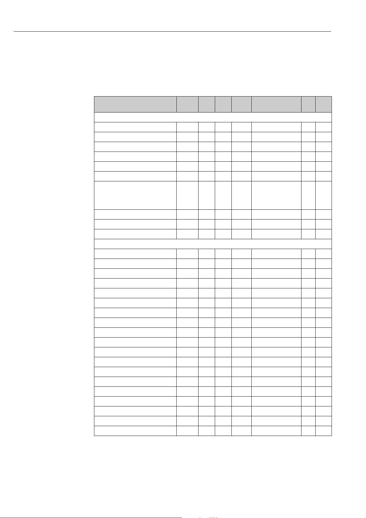
There are two Analog Input Blocks in the Smartec S transmitter. These are distributed to
slots 1 and 2 in the following order:
1. Main measured value (Main Process Value)
2. Measured temperature value (Temperature)
Parameter E+H
Matrix
Standard parameter
BLOCK_OBJECT 1 - 2 16 20 DS-32* r C
ST_REV 1 - 2 17 2 Unsigned16 r N
TAG_DESC 1 - 2 18 32 Octetstring r, w S
STRATEGY 1 - 2 19 2 Unsigned16 r, w S
ALERT_KEY 1 - 2 20 1 Unsigned8 r, w S
TARGET_MODE 1 - 2 21 1 Unsigned8 r, w S
MODE_BLK
Actual
Permitted
Normal
ALARM_SUM 1 - 2 23 8 DS-42* r D
BATCH 1 - 2 24 10 DS-67* r, w S
Gap 1 - 2 25
Block parameter
OUT 1 - 2 26 5 DS-33* r D
PV_SCALE 1 - 2 27 8 Float r, w S
OUT_SCALE 1 - 2 28 11 DS-36* r, w S
LIN_TYPE 1 - 2 29 1 Unsigned8 r, w S
CHANNEL 1 - 2 30 2 Unsigned16 r, w S
PV_FTIME 1 - 2 32 4 Float r, w S
FSAFE_TYPE 1 - 2 33 1 Unsigned8 r, w S
FSAFE_VALUE 1 - 2 34 4 Float r, w S
ALARM_HYS 1 - 2 35 4 Float r, w S
HI_HI_LIM 1 - 2 37 4 Float r, w S
HI_LIM 1 - 2 39 4 Float r, w S
LO_LIM 1 - 2 41 4 Float r, w S
LO_LO_LIM 1 - 2 43 4 Float r, w S
HI_HI_ALM 1 - 2 46 16 DS-39* r D
HI_ALM 1 - 2 47 16 DS-39* r D
LO_ALM 1 - 2 48 16 DS-39* r D
LO_LO_ALM 1 - 2 49 16 DS-39* r D
SIMULATE 1 - 2 50 6 DS-50* r, w S
VIEW_1 1 - 2 61 18 Unsigned8 r D
Slot Index Size
(bytes)
1 - 2 22 3 DS-37*
Type Acc. Store
Unsigned8
Unsigned8
Unsigned8
r
N
Cst
Cst
26 Endress+Hauser
Page 27

Smartec S CLD132/134 PROFIBUS-PA/-DP System integration
Manufacturer-specific parameters Smartec S
Parameter E+H
Matrix
Measured value V0H0 3 100 4 Float r D
Temperature V0H1 3 101 4 Float r D
Operating mode V0H2 3 102 1 Unsigned8
Unit of measurement (concentration) V0H3 3 103 1 Unsigned8
Number of decimal places V0H4 3 104 1 Unsigned8
Unit of measurement (conductivity) V0H5 3 105 1 Unsigned8
Signal damping V0H6 3 106 1 Unsigned8 r, w N
Raw value V0H7 3 107 4 Float r D
Current measuring range V0H9 3 108 1 Unsigned8 r, w N
Temperature measurement V1H0 3 109 1 Unsigned8
Process temperature V1H3 3 110 4 Float r, w N
Cell constant V1H4 3 111 4 Float r, w N
Installation factor V1H6 3 112 4 Float r, w N
Calibration temperature V1H8 3 113 4 Float r, w N
Temperature correction V1H9 3 114 4 Float r, w N
Contact function V3H0 3 115 1 Unsigned8
Switch-on delay V3H3 3 116 2 Unsigned16 r, w N
Switch-off delay V3H4 3 117 2 Unsigned16 r, w N
Number of binary inputs V4H0 3 118 1 Unsigned8 r, w N
Source of binary inputs V4H1 3 119 1 Unsigned8
Processed measuring range V4H2 3 120 1 Unsigned8 r, w N
Operating mode of processed
measuring range
Substance selection of processed
measuring range
V4H3 3 121 1 Unsigned8
V4H4 3 122 1 Unsigned8
Slot Index Size
(bytes)
Type Acc. Store
rD
0: Conductivity
1: Concentration
r, w N
57: %
139: ppm
245: mg/l
106: tds
251: without
r, w N
0: X.xxx
1: XX.xx
2: XXX.x
3: XXXX
r, w N
66: mS/cm
67: μm/cm
240: S/m
r, w N
0: fixed
1: Pt 100
2: Pt 1000
3: NTC
r, w N
0: Alarm function
1: Limit function
2: Limit + alarm fct.
r, w N
0: binary contacts
1: cyclic data
r, w N
0: Conductivity
1: Concentration
r, w N
0: NaOH
1: H2SO4
2: H3PO4
3: HNO3
4: User 1...
Endress+Hauser 27
Page 28

System integration Smartec S CLD132/134 PROFIBUS-PA/-DP
Parameter E+H
Matrix
Temperature compensation of
processed measuring range
Alpha value of processed measuring
range
Switch-on point of processed
measuring range
Switch-off point of processed
measuring range
Correction factor V5H0 3 127 4 Float r, w N
Substance selection V5H1 3 128 1 Unsigned8
Current concentration table V5H2 3 129 1 Unsigned8 r, w D
Read/edit concentration table V5H3 3 130 1 Unsigned8
Number of concentration table
elements
Selection of concentration table
elements
Conductivity concentration table V5H6 3 133 4 Float r, w N
Concentration concentration table V5H7 3 134 4 Float r, w N
Temperature concentration table V5H8 3 135 4 Float r, w N
Status concentration table V5H9 3 136 1 Unsigned8
Current alpha table V6H0 3 137 1 Unsigned8
Read/edit alpha table V6H1 3 138 1 Unsigned8
Number of alpha table elements V6H2 3 139 1 Unsigned8 r, w N
Selection of alpha table elements V6H3 3 140 1 Unsigned8 r, w D
Temperature alpha table V6H4 3 141 4 Float r, w N
Alpha value alpha table V6H5 3 142 4 Float r, w N
Status alpha table V6H6 3 143 1 Unsigned8
PCS alarm V7H0 3 144 1 Unsigned8
V4H5 3 123 1 Unsigned8
V4H6 3 124 4 Float r, w N
V4H8 3 125 4 Float r, w N
V4H9 3 126 4 Float r, w N
V5H4 3 131 1 Unsigned8 r, w N
V5H5 3 132 1 Unsigned8 r, w D
Slot Index Size
(bytes)
Type Acc. Store
r, w N
0: without
1: linear
2: NaCl
3: User 1...
rD
0: NaOH
1: H2SO4
2: H3PO4
3: HNO3
4: User 1...
r, w D
0: read
1: edit
rD
0: Ok
1: Service
2: Processing
3: Invalid
r, w D
1: User
r, w D
0: read
1: edit
rD
0: Ok
1: Service
2: Processing
3: Invalid
r, w N
0: no PCS
1: 1 hour
2: 2 hours
3: 4 hours
28 Endress+Hauser
Page 29
Smartec S CLD132/134 PROFIBUS-PA/-DP System integration
Parameter E+H
Matrix
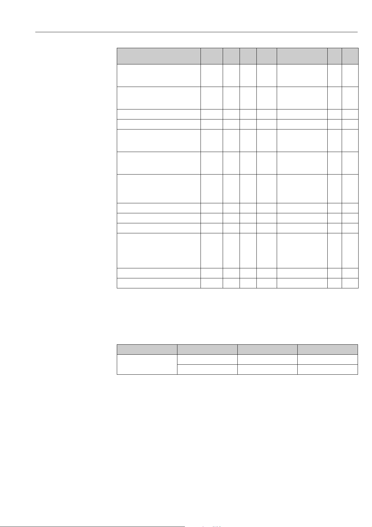
Relaiy contact type V8H1 3 145 1 Unsigned8
Relay time unit V8H2 3 146 1 Unsigned8
Alarm delay V8H3 3 147 2 Unsigned16 r, w N
Diagnostic code selection V8H4 3 148 1 Unsigned8 r, w D
Alarm status V8H5 3 149 1 Unsigned8
Alarm relay V8H6 3 150 1 Unsigned8
Security locking V8H9 3 151 2 Unsigned16
Hold function V9H0 3 152 1 Unsigned8 r, w N
Hold dwell period V9H1 3 153 2 Unsigned16 r, w N
MRS version V9H2 3 154 1 Unsigned8 r Cst
Factory values V9H4 3 155 1 Unsigned8
SW version VAH5 3 156 2 Unsigned16 r Cst
HW version VAH6 3 157 2 Unsigned16 r Cst
Slot Index Size
(bytes)
Type Acc. Store
r, w N
0: steady contact
1: fleeting contact
r, w N
0: seconds
1: minutes
rD
0: no
1: yes
r, w N
0: no
1: yes
r, w N
22: not protected
9998: loc. op. disabl.
9999: hardware prot.
r, w D
1: Device data
2: Sensor data
3: User data
4: Address data
Data strings
Some data types in the slot/index table (e. g. DS-33) are marked with a asterisk (*). These
data types are data strings which are structured as per the PROFIBUS Specification Part 1,
Version 3.0. They consist of several elements which are additionally addressed via a subindex, as shown in the following example.
Parameter type Sub-index Type Size (byte)
DS-33 1 Float 4
5 Unsigned8 1
Endress+Hauser 29
Page 30
Commissioning Smartec S CLD132/134 PROFIBUS-PA/-DP
WARNING
!
6 Commissioning
6.1 Function check
Incorrect connection, incorrect supply voltage
Safety risks for staff and incorrect operation of the device
‣ Check that all connections have been established correctly in accordance with the wiring
diagram.
‣ Make sure that the supply voltage matches the voltage indicated on the nameplate.
6.2 Setting of device address
The address must be set for each PROFIBUS device. The process control system does not
recognize the transmitter if the address is not set correctly.
All devices have the address 126 on leaving the factory. You can use this address for device
function checking and for connection to a PROFIBUS PA network. You must change this
address to be able to integrate additional devices.
The device address can be set via:
• Local operation
• PROFIBUS communication
• DIL switch in the device
Valid device addresses are in the range 0 to 125.
Each address may only be given once in a PROFIBUS network.
The double arrow in the display indicates active communication with PROFIBUS.
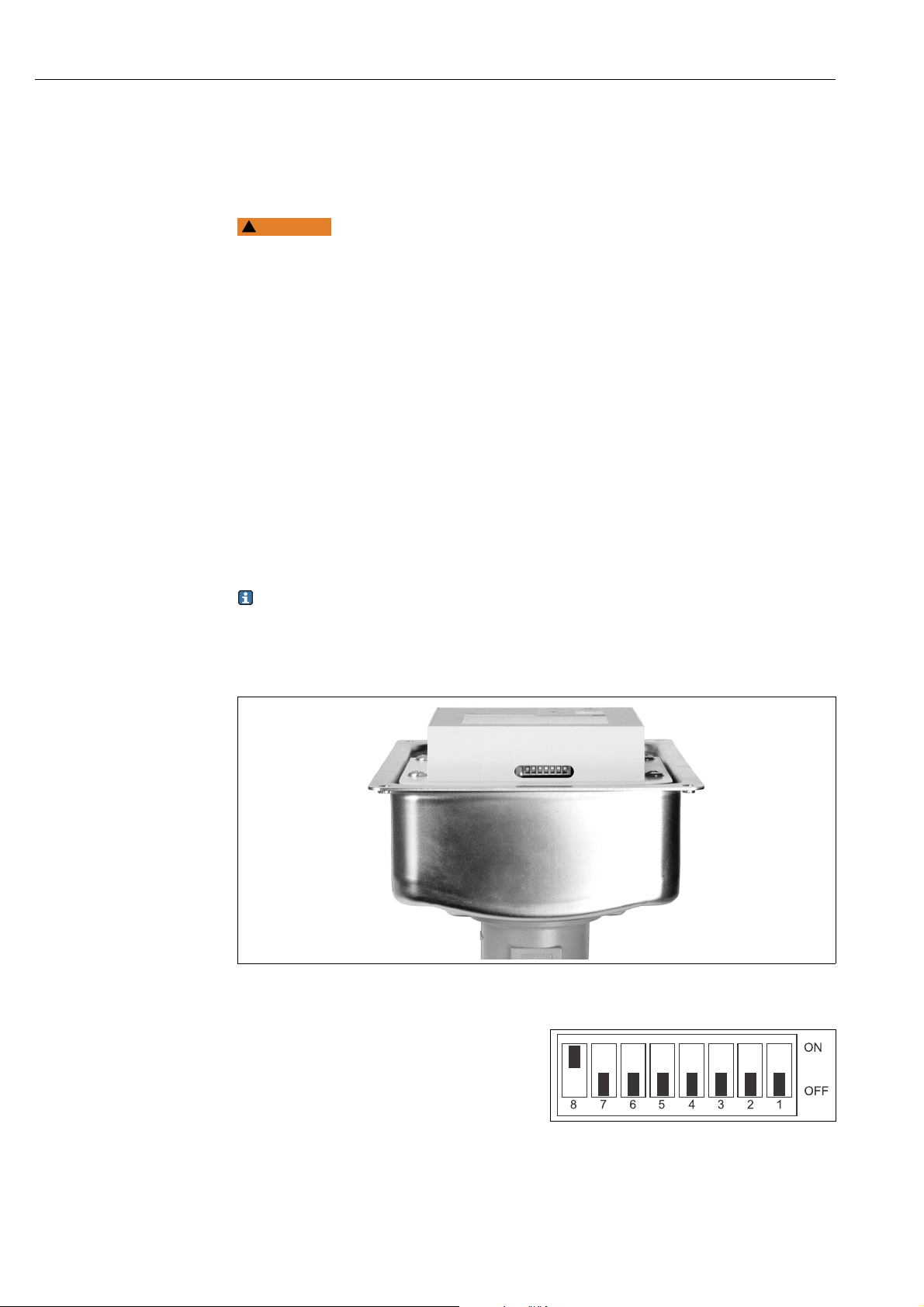
Position of the DIL switch
Fig. 12: Position of the DIL switch (only accessible with open housing cover)
You can only set the address via the
software if DIL switch 8 is set to "ON". The
factory setting of the DIL switch is "ON"
( å 13).
a0005929
Fig. 13: Factory setting of the DIL switch
30 Endress+Hauser
a0005211
Page 31
Smartec S CLD132/134 PROFIBUS-PA/-DP Commissioning
126
I1
Address
Set the device address via the INTERFACE
function group in menu field I1.
Setting the device address via PROFIBUS communication
The address is set via the Set_Slave_Add service.
Setting the device address via DIL switch (hardware setting)
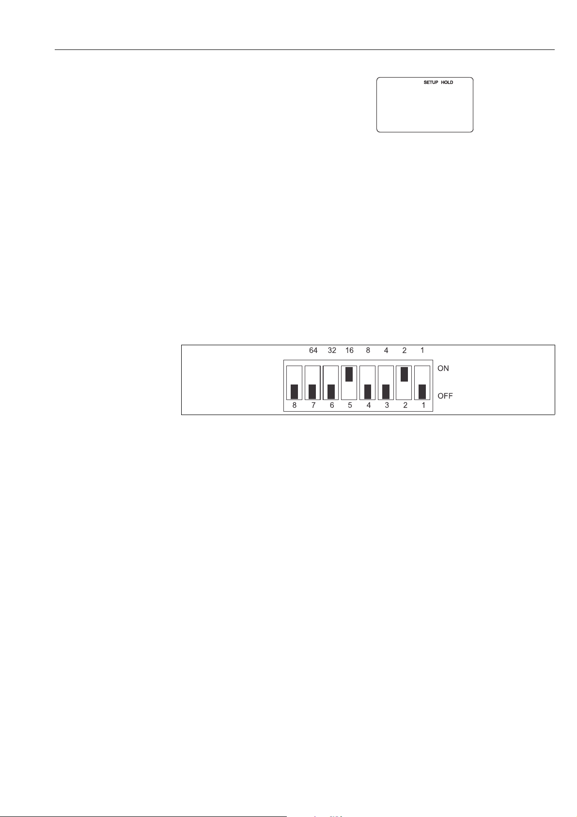
Please proceed as follows to set the device address:
1. Loosen the four Phillips screws and remove the housing cover. The DIL switch is
situated on the electronic module above the display.
2. Set the device address (from 0 to 126) at switches 1 to 7.
Example: 18 = 2 + 16 (switch 2 and switch 5 = ON)
3. Set switch 8 to "OFF".
4. Close the housing cover.
Fig. 14: Hardware setting of the device address (example address = 18)
a0005212
Endress+Hauser 31
Page 32

Commissioning Smartec S CLD132/134 PROFIBUS-PA/-DP
6.3 Device data and type files
The device data base (GSD) is required to configure a PROFIBUS DP network. The GSD (a
simple text file) describes e. g. which data transfer rate is supported by the device or which
digital information in which format the PLC receives from the device.
Each device is assigned an ID number by the PROFIBUS use organization (PNO). The name
of the device data base (GSD) is derived from this ID number.
For Endress+Hauser devices the ID number always starts with "15XX".
Types of Device Master Files
Prior to configuration, decide which GSD you want to use to operate the system.
You can change the setting by means of a Class 2 master (under Physical Block -
Parameter Ident_Number_Selector).
Generally, the following Device Master Files with different functionalities are available to
you:
• Manufacturer-specific GSD with Profile 3.0 functionality:
This GSD guarantees the unlimited functionality of the field device. Device-specific process
parameters and functions are therefore available.
• Manufacturer-specific GSD with Profile 2.0 functionality:
This GSD guarantees downward compatibility to the Smartec S transmitter with Profile 2.0
functionality. With this you can use the Smartec S transmitter with Profile 3.0
functionality even in applications with Smartec S transmitter with Profile 2.0
functionality.
• Profile GSD
If a system is configured with profile GSDs, it is possible to exchange devices that are
supplied by various manufacturers. It is, however, essential that the cyclic process values
follow the same sequence.
Example:
The Smartec S transmitter supports the profile GSD PA139750.gsd (IEC 61158-2). This GSD
comprises AI blocks. The AI blocks are always assigned to the following measured variables:
AI 1 = Main process value
AI 2 = Temperature
This guarantees that the first measured variable agrees with the field devices of other
manufacturers.
32 Endress+Hauser
Page 33

Smartec S CLD132/134 PROFIBUS-PA/-DP Commissioning
Name of device ID no. GSD Ident_Number_
Selector
Smartec S - only Profile 3.0 functionality:
Smartec S PA 9750 Hex PA139750.gsd 0 PA_9750n.bmp
Smartec S DP 9750 Hex PA039750.gsd 0 PA_9750n.bmp
Smartec S - manufacturer-specific functions with Profile 2.0 functionality:
Smartec S PA
additional cycl. data
for
digital I/O (parameter
set switch)
Smartec S DP
additional cycl. data
for
digital I/O (parameter
set switch)
Smartec S - manufacturer-specific functions with Profile 2.0 functionality:
Smartec S PA 151B Hex EH__151B.gsd 2
Smartec S DP 151A Hex EH__151A.gsd 2
153E Hex EH3x153E.gsd 1
153D Hex EH3x153D.gsd 1
Bitmaps
EH153E_d.bmp
EH153E_n.bmp
EH153E_s.bmp
EH153D_d.bmp
EH153D_n.bmp
EH153D_s.bmp
EH151B_d.bmp
EH151B_n.bmp
EH151B_s.bmp
EH151A_d.bmp
EH151A_n.bmp
EH151A_s.bmp
The GSD files for all Endress+Hauser devices can be obtained from the following sources:
•Via the Internet:
– E+H: http://www.endress.com
– PNO: http://www.profibus.com
• On CD-ROM from E+H; order no. 56003894
Contents of the download file and of CD-ROM:
• All Endress+Hauser GSD files
• All Endress+Hauser bitmap files
• Useful information on the devices
Content structure of GSD files from Endress+Hauser
For the E+H transmitter with PROFIBUS interface, you receive all the data needed for
configuration with one exe-file. Once unpacked, this file automatically creates the following
structure:
At the top level, you have the measuring parameters available for the transmitter. Beneath
this, you can find:
• Revision x.xx” folder
This ID stands for the special device version. Device-specific bitmaps can be found in the
“BMP” and “DIB” subdirectories.
•"GSD" folder
• “Info” folder:
Information relating to the transmitter and any dependencies in the device software.
Please read the information in the "Info" folder carefully before configuring.
Endress+Hauser 33
Page 34

Commissioning Smartec S CLD132/134 PROFIBUS-PA/-DP
Working with the GSD / type files
The GSD files must be copied to a specific subdirectory of the PROFIBUS DP configuration
software of your PLC.
Example:
Siemens S7-300/400 PLC with configuration software Siemens STEP 7
• Copy the GSD files to the subdirectory:
...\siemens\step7\s7data\gsd
• The bitmap files also belong to the GSDs. These bitmap files are used to display the
measuring points in image form. Load the bitmap files to the directory:
...\siemens\step7\s7data\nsbmp
If you are using configuration software other than that referred to above, ask your PLC
manufacturer which directory you should use.
34 Endress+Hauser
Page 35
Smartec S CLD132/134 PROFIBUS-PA/-DP Diagnostics and troubleshooting
7 Diagnostics and troubleshooting
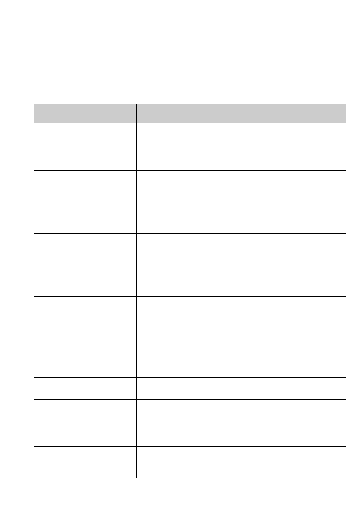
System error messages
The DIAGNOSIS and DIAGNOSIS_EXTENSION parameters are generated from the devicespecific errors.
Smartec S PROFIBUS diagnosis
NAMUR
class
Failure E001 Memory error 01 00 00 80 - DIA_HW_ELECTR 01 00 00 00 00 00BAD device failure 0C
Failure E002 Data error in EEPROM 10 00 00 80 - DIA_MEM_CHKSUM 02 00 00 00 00 00BAD device failure 0C
Failure E003 Invalid configuration 00 04 00 80 - DIA_CONF_INVAL 04 00 00 00 00 00BAD device failure 0C
Failure E007 Transmitter faulty 20 00 00 80 - DIA_MEASUREMENT 08 00 00 00 00 00BAD device failure 0C
Failure E008 Sensor or sensor
Failure E010 Temperature sensor
Failure E025 Limit value for airset offset
Failure E036 Sensor calibration range
Failure E037 Sensor calibration range
Failure E045 Calibration aborted 20 00 00 80 - DIA_MEASUREMENT 00 02 00 00 00 00BAD configuration
Failure E049 Installation factor
Failure E050 Installation factor
Failure E055 Measuring range of the
Failure E057 Measuring range of the
Failure E059 Temperature range
Failure E061 Temperature range
Failure E067 Limit contactor setpoint
Failure E077 Temperature outside of the
Failure E078 Temperature outside of the
Failure E079 Conductivity outside of the
Funct.
check
Error
no.
E101 Service function active – –
Description DIAGNOSIS DIAGNOSIS_
20 00 00 80 - DIA_MEASUREMENT 10 00 00 00 00 00BAD sensor failure 10
connection faulty
20 00 00 80 - DIA_MEASUREMENT 20 00 00 00 00 00BAD sensor failure 10
defective
20 00 00 80 - DIA_MEASUREMENT 40 00 00 00 00 00BAD configuration
exceeded
20 00 00 80 - DIA_MEASUREMENT 80 00 00 00 00 00BAD configuration
exceeded
20 00 00 80 - DIA_MEASUREMENT 00 01 00 00 00 00BAD configuration
undershot
20 00 00 80 - DIA_MEASUREMENT 00 04 00 00 00 00BAD configuration
exceeded
00 20 00 80 - DIA_MAINTENANCE 00 08 00 00 00 00BAD configuration
undershot
20 00 00 80 - DIA_MEASUREMENT 00 10 00 00 00 00UNCERTAIN sensor
main parameter undershot
20 00 00 80 - DIA_MEASUREMENT 00 20 00 00 00 00UNCERTAIN sensor
main parameter exceeded
20 00 00 80 - DIA_MEASUREMENT 00 40 00 00 00 00UNCERTAIN sensor
undershot
20 00 00 80 - DIA_MEASUREMENT 00 80 00 00 00 00UNCERTAIN sensor
exceeded
00 20 00 80 - DIA_MAINTENANCE 00 00 00 04 00 00UNCERTAIN non-specific 40
exceeded
00 04 00 80 - DIA_CONF_INVAL 00 00 01 00 00
value table
00 04 00 80 - DIA_CONF_INVAL 00 00 02 00 00 00BAD configuration
concentration table
0 04 00 80 - DIA_CONF_INVAL 00 00 04 00 00 00BAD configuration
concentration table
EXTENSION
00
Measured value status
Quality Sub-Status Hex*
BAD configuration
04
error
04
error
04
error
04
error
04
error
5C
error
50
conversion not
accurate
50
conversion not
accurate
50
conversion not
accurate
50
conversion not
accurate
04
error
04
error
04
error
Endress+Hauser 35
Page 36

Diagnostics and troubleshooting Smartec S CLD132/134 PROFIBUS-PA/-DP
NAMUR
class
Funct.
check
Funct.
check
Failure E116 Download error 00 04 00 80 - DIA_CONF_INVAL 00 00 08 00 00 00BAD configuration
Maint. E150 Distance of the
Failure E152 Live-Check alarm (PCS) 20 00 00 80 - DIA_MEASUREMENT 00 00 00 02 00 00BAD sensor failure 10
Error
no.
E102 Manual operation active - -
E106 Download active 00 00 00 80 -
Description DIAGNOSIS DIAGNOSIS_
EXTENSION
00 00 00 00 00 80--
EXTENSION_AVAILABLE
00 20 00 80 - DIA_MAINTENANCE 00 00 00 01 00 00UNCERTAIN configuration
temperature values or
value table too low
Measured value status
Quality Sub-Status Hex*
04
error
5C
error
* Depending on the limit bits you have to add from 00 up to 03
36 Endress+Hauser
Page 37
Smartec S CLD132/134 PROFIBUS-PA/-DP Accessories
E+H
PROFIBUS-PA
PROFIBUS-DP
ENDRESS+HAUSER
SMARTECS
ENDRESS+HAUSER
SMARTECS
ALARM
CAL
E
+
–
ENDRESS+HAUSER
SMARTECS
ENDRESS+HAUSER
SMARTECS
ALARM
CAL
E
+
–
ENDRESS+HAUSER
SMARTECS
ENDRESS+HAUSER
SMARTECS
ALARM
CAL
E
+
–
1
2
3
4
5
6
7
8
9
8
5
n.c.
n.c.
A (PA-)
A (PA-)
S
S
B (PA+)
B (PA+)
A (PA-)
S (PE)
B (PA+)
45
1.77”
7
0.28”
150 / 300
5.91” / 11.81”
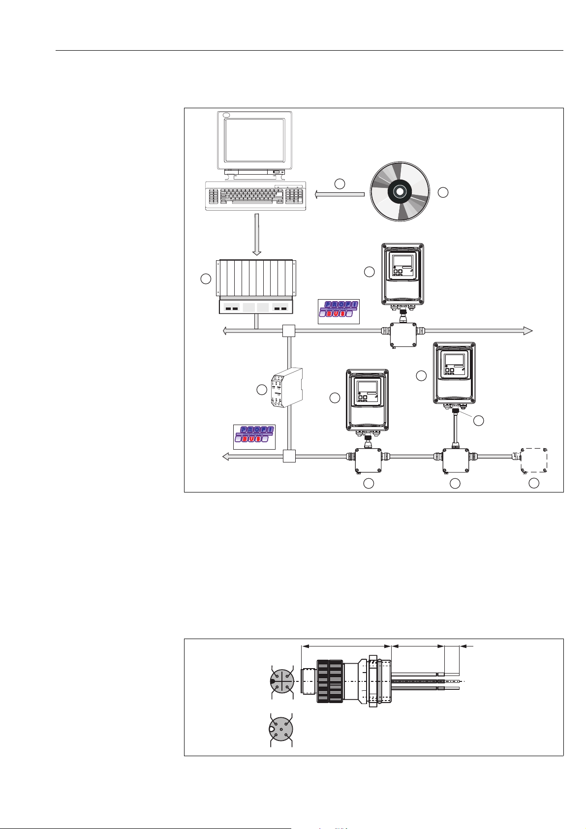
8 Accessories
Fig. 15: Instrumentation overview Smartec S PROFIBUS
1 PLC configuration tools 6 Smartec S separate mounting
2 GSD 7 M12 plug
3 PLC 8 Fieldbus connection box
4 Segment coupler 9 Bus termination box
5 Smartec S direct mounting
• Four-pole metal plug for mounting to the transmitter
For connection to the connection box or to a cable socket. Cable length 150 mm (5.90").
order no. 51502184
Fig. 16: M-12 plug with socket
Endress+Hauser 37
a0005936
a0006068
Page 38
Accessories Smartec S CLD132/134 PROFIBUS-PA/-DP
n.c.
A (PA-)
B (PA+)
B (PA+)
S
C2
64/2.52
18.5/ 18.5/
0.73 0.73
58/2.28
17.5/0.69
37/1.46
mm/inch
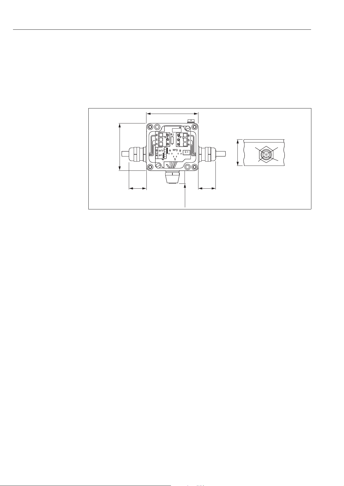
• PROFIBUS connection box
For direct mounting to the transmitter.
Aluminum housing, IP 67, with four-pole plug connector and bus termination, two cable
threads Pg 9.
order no. 017 481-0130
• PROFIBUS connection box with grounding capacitor
as above, additional internal grounding capacitor.
order no. 017 481-0110
a0005214
Fig. 17: Fieldbus connection box for PA
• Metal Y-adapter with two cable glands Pg 13.5.
order no. 51502183
• Ready-made cable with M12 plug and M12 coupling of hard PU and nickel-plated brass
threads. IP 67, screen connected to the thread, PVC sheath, twisted and screened
conductor pair 2/18 AWG, temperature range –40 to +70 °C (–40 to +178 °F).
– Cable length 1 m (3.28 ft), order no. 52001025
– Cable length 2 m (6.56 ft), order no. 52001040
– Cable length 5 m (16.41 ft), order no. 52001041
– Cable length 10 m (32.81 ft), order no. 52001042
• FieldCare
Tool for Plant Asset Management
Supports Ethernet, HART, PROFIBUS, FOUNDATION Fieldbus
FieldCare Standard, order no. SFE551-xxxx
FieldCare Professional, order no. SFE552-xxxx
38 Endress+Hauser
Page 39

Smartec S CLD132/134 PROFIBUS-PA/-DP Technical data
9Technical data
9.1 Output PROFIBUS-PA
Output signal PROFIBUS PA acc. to EN 50170 vol. 2, profile version 3.0
PA function Slave
Transmission rate 31.25 kbps
Signal coding Manchester II
Response time slave Approx. 20 ms
Signal on alarm Status and alarm messages in accordance with PROFIBUS PA, profile version 3.0
Display: error code
Physical layer IEC 61158-2, MBP (Manchester bus coded)
Bus voltage 9 to 32 V
Bus error consumption 10 mA ±1 mA
Error current consumption
I
FDE
0 mA
9.2 Output PROFIBUS-DP
Output signal PROFIBUS DP acc. to EN 50170 vol. 2, profile version 3.0
DP function Slave
Transmission rate 9.6 kbps, 19.2 kbps, 45.45 kbps, 93.75 kbps, 187.5 kbps,
500 kbps, 1.5 Mbps
Signal coding NRZ code
Response time slave Approx. 20 ms
Signal on alarm Status and alarm messages in accordance with PROFIBUS DP, profile version 3.0
Display: error code
Physical layer RS 485
Endress+Hauser 39
Page 40

Technical data Smartec S CLD132/134 PROFIBUS-PA/-DP
9.3 Display and user interface
Local operation Via keyboard
PC operation Via PROFIBUS with FieldCare
Bus address Set via DIL switch or
via operating menu or
via Set_Slave_Adr service
Communication interface PROFIBUS PA/DP
9.4 Standards and guidelines
PROFIBUS EN 50170, vol. 2
PROFIBUS DP EN 50170, vol. 2
RS 485
PNO guidelines for PROFIBUS DP
PROFIBUS PA EN 50170, vol. 2
RS 485
PNO guidelines for PROFIBUS PA
40 Endress+Hauser
Page 41

Smartec S CLD132/134 PROFIBUS-PA/-DP Technical data
Endress+Hauser 41
Page 42

Smartec S CLD132/134 PROFIBUS-PA/-DP
Index
A
Acyclical data exchange . . . . . . . . . . . . . . . . . . . . . . . . . . 22
Address . . . . . . . . . . . . . . . . . . . . . . . . . . . . . . . . . . . . . . . . 30
B
Block model . . . . . . . . . . . . . . . . . . . . . . . . . . . . . . . . . . . . 12
C
Communication . . . . . . . . . . . . . . . . . . . . . . . . . . . . . . . . . 12
Customizing the cyclic data telegram . . . . . . . . . . . . . . . 20
Cyclic data telegram . . . . . . . . . . . . . . . . . . . . . . . . . . . . . 20
Cyclical data exchange . . . . . . . . . . . . . . . . . . . . . . . . . . . 18
D
Data exchange
Acyclical . . . . . . . . . . . . . . . . . . . . . . . . . . . . . . . . . . . . 22
Cyclical . . . . . . . . . . . . . . . . . . . . . . . . . . . . . . . . . . . . . 18
Designated use. . . . . . . . . . . . . . . . . . . . . . . . . . . . . . . . . . . . 4
Device address . . . . . . . . . . . . . . . . . . . . . . . . . . . . . . . . . . 30
Device data file. . . . . . . . . . . . . . . . . . . . . . . . . . . . . . . . . . 32
Diagnostics . . . . . . . . . . . . . . . . . . . . . . . . . . . . . . . . . . . . . 35
Display. . . . . . . . . . . . . . . . . . . . . . . . . . . . . . . . . . . . . . . . . 11
E
Electrical connection . . . . . . . . . . . . . . . . . . . . . . . . . . . . . . . 8
Electromagnetic compatibility . . . . . . . . . . . . . . . . . . . . . . . 4
S
Safety instructions . . . . . . . . . . . . . . . . . . . . . . . . . . . . . . . . 4
Set device address . . . . . . . . . . . . . . . . . . . . . . . . . . . . . . . . 30
Slot/index tables . . . . . . . . . . . . . . . . . . . . . . . . . . . . . . . . . 23
Standards and guidelines . . . . . . . . . . . . . . . . . . . . . . . . . . 40
Statuscodes . . . . . . . . . . . . . . . . . . . . . . . . . . . . . . . . . . . . . 20
System equipment. . . . . . . . . . . . . . . . . . . . . . . . . . . . . . . . . 6
System error messages . . . . . . . . . . . . . . . . . . . . . . . . . . . . 35
System integration . . . . . . . . . . . . . . . . . . . . . . . . . . . . . . . 12
T
Troubleshooting . . . . . . . . . . . . . . . . . . . . . . . . . . . . . . . . . 35
Type files . . . . . . . . . . . . . . . . . . . . . . . . . . . . . . . . . . . . . . . 32
W
Workplace safety. . . . . . . . . . . . . . . . . . . . . . . . . . . . . . . . . . 4
F
FieldCare. . . . . . . . . . . . . . . . . . . . . . . . . . . . . . . . . . . . . . . 11
Floating-point number . . . . . . . . . . . . . . . . . . . . . . . . . . . 19
Function check. . . . . . . . . . . . . . . . . . . . . . . . . . . . . . . . . . 30
I
IEEE floating-point number . . . . . . . . . . . . . . . . . . . . . . . 19
Input-Daten . . . . . . . . . . . . . . . . . . . . . . . . . . . . . . . . . . . . 18
O
Operation . . . . . . . . . . . . . . . . . . . . . . . . . . . . . . . . . . . . . . 11
FieldCare. . . . . . . . . . . . . . . . . . . . . . . . . . . . . . . . . . . . 11
Operational safety . . . . . . . . . . . . . . . . . . . . . . . . . . . . . . . . . 4
Output
DP . . . . . . . . . . . . . . . . . . . . . . . . . . . . . . . . . . . . . . . . . 39
PA . . . . . . . . . . . . . . . . . . . . . . . . . . . . . . . . . . . . . . . . . 39
P
Post connection check. . . . . . . . . . . . . . . . . . . . . . . . . . . . 10
Post-installation check . . . . . . . . . . . . . . . . . . . . . . . . . . . . . 7
Product safety . . . . . . . . . . . . . . . . . . . . . . . . . . . . . . . . . . . . 5
R
Requirements for the personnel . . . . . . . . . . . . . . . . . . . . . 4
42 Endress+Hauser
Page 43

Smartec S CLD132/134 PROFIBUS-PA/-DP
Endress+Hauser 43
Page 44

www.addresses.endress.com
71228814
 Loading...