

Page 1
Operating Instructions
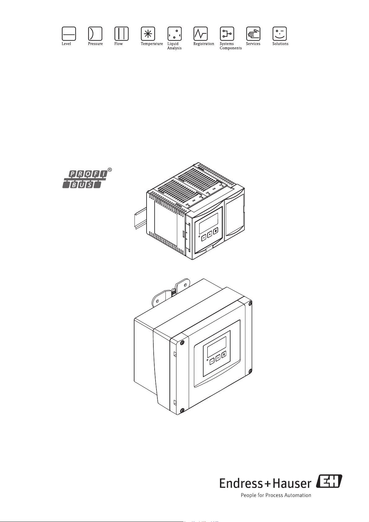
Prosonic S FMU95
Transmitter for 5 or 10 ultrasonic sensors
BA00344F/00/EN/13.12
71164423
Page 2

Page 3

Prosonic S FMU95 Table of Contents
Table of Contents
1 Safety Instructions . . . . . . . . . . . . . . . . 4
1.1 Designated use . . . . . . . . . . . . . . . . . . . . . . . . . . . . 4
1.2 Installation, commissioning, operation . . . . . . . . . . . 4
1.3 Operational safety and process safety . . . . . . . . . . . . 4
1.4 Notes on safety conventions and symbols . . . . . . . . . 5
2 Identification . . . . . . . . . . . . . . . . . . . . 6
2.1 Parts of the Prosonic S FMU95 . . . . . . . . . . . . . . . . 6
2.2 Nameplate (Example) . . . . . . . . . . . . . . . . . . . . . . . 7
2.3 Product structure . . . . . . . . . . . . . . . . . . . . . . . . . . 8
2.4 Scope of delivery . . . . . . . . . . . . . . . . . . . . . . . . . . . 9
2.5 Certificates and approvals . . . . . . . . . . . . . . . . . . . . 9
2.6 Registered trademarks . . . . . . . . . . . . . . . . . . . . . . . 9
3 Installation . . . . . . . . . . . . . . . . . . . . . 10
3.1 Incoming acceptance, transport, storage . . . . . . . . . 10
3.2 Mounting the field housing . . . . . . . . . . . . . . . . . . 10
3.3 Mounting the DIN-rail housing . . . . . . . . . . . . . . . 12
3.4 Mounting the remote display and operating module 13
3.5 Mounting of the sensors . . . . . . . . . . . . . . . . . . . . 14
3.6 Installation check . . . . . . . . . . . . . . . . . . . . . . . . . 14
4 Wiring . . . . . . . . . . . . . . . . . . . . . . . . 15
8 Maintenance . . . . . . . . . . . . . . . . . . . . 85
8.1 Exterior cleaning . . . . . . . . . . . . . . . . . . . . . . . . . . 85
8.2 Repairs . . . . . . . . . . . . . . . . . . . . . . . . . . . . . . . . . 85
8.3 Repairs to Ex-approved devices . . . . . . . . . . . . . . . 85
8.4 Replacement . . . . . . . . . . . . . . . . . . . . . . . . . . . . . 85
8.5 Replacing a sensor . . . . . . . . . . . . . . . . . . . . . . . . . 85
8.6 Spare Parts . . . . . . . . . . . . . . . . . . . . . . . . . . . . . . 86
8.7 Return . . . . . . . . . . . . . . . . . . . . . . . . . . . . . . . . . . 87
8.8 Disposal . . . . . . . . . . . . . . . . . . . . . . . . . . . . . . . . . 87
8.9 Contact addresses of Endress+Hauser . . . . . . . . . . . 87
9 Accessories . . . . . . . . . . . . . . . . . . . . . 88
9.1 Commubox FXA291 . . . . . . . . . . . . . . . . . . . . . . . 88
9.2 Protection cover for the field housing . . . . . . . . . . . 88
9.3 Mounting plate for the field housing . . . . . . . . . . . . 88
9.4 Mounting bracket . . . . . . . . . . . . . . . . . . . . . . . . . 89
9.5 Adaption plate for remote display . . . . . . . . . . . . . . 90
9.6 Overvoltage protection (in IP66 housing) . . . . . . . . 90
9.7 Overvoltage protection HAW562 . . . . . . . . . . . . . . 91
9.8 Extension cable for sensors . . . . . . . . . . . . . . . . . . 91
10 Technical Data. . . . . . . . . . . . . . . . . . . 92
10.1 Technical data at a glance . . . . . . . . . . . . . . . . . . . 92
4.1 Terminal compartment . . . . . . . . . . . . . . . . . . . . . 15
4.2 Terminal assignment . . . . . . . . . . . . . . . . . . . . . . . 18
4.3 Connection to a PROFIBIS DP network . . . . . . . . . 20
4.4 Sensor connection . . . . . . . . . . . . . . . . . . . . . . . . . 21
4.5 Shortening the sensor cable . . . . . . . . . . . . . . . . . . 23
4.6 Synchronization line. . . . . . . . . . . . . . . . . . . . . . . 24
4.7 Connection of the separate display and operating
module . . . . . . . . . . . . . . . . . . . . . . . . . . . . . . . . . 25
4.8 Potential equalization . . . . . . . . . . . . . . . . . . . . . . 26
4.9 Post-connection check . . . . . . . . . . . . . . . . . . . . . . 28
5 Operation . . . . . . . . . . . . . . . . . . . . . . 29
5.1 Operating options . . . . . . . . . . . . . . . . . . . . . . . . . 29
5.2 Operation via the display and operating module . . . 31
5.3 Operation via Endress+Hauser operating tool
"FieldCare" . . . . . . . . . . . . . . . . . . . . . . . . . . . . . . 43
6 Commissioning. . . . . . . . . . . . . . . . . . 44
6.1 Preparatory steps . . . . . . . . . . . . . . . . . . . . . . . . . . 44
6.2 Configuration of the measurement . . . . . . . . . . . . . 49
6.3 Parametrization of the Analog Input Blocks . . . . . . 68
6.4 Parametrization of the cyclic data telegram . . . . . . 69
6.5 Parametrization of the on-site display . . . . . . . . . . . 71
11 Operating menu. . . . . . . . . . . . . . . . . . 96
11.1 "level" . . . . . . . . . . . . . . . . . . . . . . . . . . . . . . . . . . 96
11.2 "safety settings" . . . . . . . . . . . . . . . . . . . . . . . . . . . 98
11.3 "outputs/calculations" . . . . . . . . . . . . . . . . . . . . . . 98
11.4 "device properties" . . . . . . . . . . . . . . . . . . . . . . . . . 99
11.5 "system information" . . . . . . . . . . . . . . . . . . . . . . 100
11.6 "display" . . . . . . . . . . . . . . . . . . . . . . . . . . . . . . . 102
11.7 "sensor management" . . . . . . . . . . . . . . . . . . . . . . 102
12 Appendix. . . . . . . . . . . . . . . . . . . . . . 103
12.1 Default Block Configuration . . . . . . . . . . . . . . . . . 103
Index . . . . . . . . . . . . . . . . . . . . . . . . . . . . . 105
7 Troubleshooting . . . . . . . . . . . . . . . . . 74
7.1 System error messages . . . . . . . . . . . . . . . . . . . . . . 74
7.2 Possible calibration errors . . . . . . . . . . . . . . . . . . . 80
7.3 Envelope curve display . . . . . . . . . . . . . . . . . . . . . 81
7.4 Software history . . . . . . . . . . . . . . . . . . . . . . . . . . 84
Endress + Hauser 3
Page 4

Safety Instructions Prosonic S FMU95
1Safety Instructions
1.1 Designated use
The Prosonic S FMU95 is a transmitter for up to 10 ultrasonic sensors FDU90, FDU91, FDU91F,
FDU92, FDU93, FDU95 and FDU96. The sensors of the class FDU8x can be connected as well.
Functions:
• display of up to 10 measuring values
• interference echo suppression for each connected sensor
• linearistaion for each sensor individually programmable
• configurable calculation of sums and average values
• measuring value transmission via PROFIBUS DP
1.2 Installation, commissioning, operation
The Prosonic S FMU95 is fail-safe and constructed to the state-of-the-art. It meets the appropriate
standards and EC directives. However, if you use it improperly or other than for its designated use,
it may pose application-specific hazards, e.g. product overflow due to incorrect installation or
configuration. Installation, electrical connection, start-up, operation and maintenance of the
measuring device must therefore be carried out exclusively by trained specialists authorised by the
system operator. Technical personnel must have read and understood these operating instructions
and must adhere to them. You may only undertake modifications or repair work to the device when
it is expressly permitted by the operating instructions.
#
1.3 Operational safety and process safety
Alternative monitoring measures must be taken to ensure operational safety and process safety
during configuration, testing and maintenance work on the device.
Hazardous areas
Measuring systems for use in hazardous environments are accompanied by separate "Ex
documentation", which is an integral part of this Operating Manual. Strict compliance with the
installation instructions and ratings as stated in this Additional documentation is mandatory.
• Ensure that all personnel are suitably qualified.
• Observe the specifications in the certificate as well as national and local regulations.
The transmitter may only be installed in suitable areas. Sensors with a certificate for hazardous areas
may be connected to a transmitter without a certificate.
Warning!
The sensors FDU83, FDU84, FDU85 and FDU86 with an ATEX, FM or CSA certificate are not
certified for connection to the FMU90 transmitter.
For installations in the USA:
Installation should be in accordance with the National Electrical Code NFPA 70 (NEC)
For installations in Canada:
Installation should be in accordance with the Canadian Electrical Code (CEC)
4 Endress + Hauser
Page 5

Prosonic S FMU95 Safety Instructions
t >85°C
1.4 Notes on safety conventions and symbols
In order to highlight safety-relevant or alternative operating procedures in the manual, the following
conventions have been used, each indicated by a corresponding symbol in the margin.
Safety conventions
Warning!
#
"
!
Explosion protection
0
A warning highlights actions or procedures which, if not performed correctly, will lead to personal
injury, a safety hazard or destruction of the instrument
Caution!
Caution highlights actions or procedures which, if not performed correctly, may lead to personal
injury or incorrect functioning of the instrument
Note!
A note highlights actions or procedures which, if not performed correctly, may indirectly affect
operation or may lead to an instrument response which is not planned
Device certified for use in explosion hazardous area
If the device has this symbol embossed on its name plate it can be installed in an explosion hazardous
area
-
.
Electrical symbols
%
&
)
*
+
Explosion hazardous area
Symbol used in drawings to indicate explosion hazardous areas. Devices located in and wiring
entering areas with the designation “explosion hazardous areas” must conform with the stated type
of protection.
Safe area (non-explosion hazardous area)
Symbol used in drawings to indicate, if necessary, non-explosion hazardous areas. Devices located in
safe areas still require a certificate if their outputs run into explosion hazardous areas
Direct voltage
A terminal to which or from which a direct current or voltage may be applied or supplied
Alternating voltage
A terminal to which or from which an alternating (sine-wave) current or voltage may be applied or
supplied
Grounded terminal
A grounded terminal, which as far as the operator is concerned, is already grounded by means of an
earth grounding system
Protective grounding (earth) terminal
A terminal which must be connected to earth ground prior to making any other connection to the
equipment
Equipotential connection (earth bonding)
A connection made to the plant grounding system which may be of type e.g. neutral star or
equipotential line according to national or company practice
Temperature resistance of the connection cables
States, that the connection cables must be resistant to a temperature of at least 85 °C.
Endress + Hauser 5
Page 6
Identification Prosonic S FMU95
M
ade
inG
erm
an
y
D
-79
6
89
M
a
u
lb
u
rg
MadeinGer
m
a
ny
D-79689Maulbu
rg
P
r
o
s
o
n
i
c
S
Prosonic
S
T
a
>
6
0
°
C
:
T
a
>
60°C
:
II
3
D
T
=
x
x
x
°
C
II
3
D
T=xxx°C
I
P
6
6
/
N
E
M
A
4
X
I
P66
/
NEMA4X
X
A
xx
x
F
-
A
XAx
xxF-A
D
a
t.
/
I
n
s
p
.
:
Dat./Insp.:
ifm
od
ifi
cat
io
n
se
e
s
e
p.
la
be
l
if
mod
ification
seesep.la
b
el
X=X
=
1
0
,
5
…3
2
V
D
C
1
0
W
10,5…32
V
DC
10W
4…2
0
m
A
H
A
R
T
4…20
m
AHART
O
r
d
e
r
C
o
d
e
:
S
e
r
.-
N
o
.:
5
A
0
1
0
9
0
1
0
9
A
F
M
U
9
0
-
J
1
1
A
B
1
11
A
A
1
A
Order
Code:
Ser.-No.: 5A010901
0
9A
FMU
90
-J11A
B111AA1A
M
a
d
e
inG
e
r
m
a
n
y
D
-
7
9
6
8
9
M
a
u
l
b
u
r
g
MadeinGermany
D-79689Maulburg
P
r
o
s
o
n
i
c
S
Prosonic
S
O
r
d
e
r
C
o
d
e
:
S
e
r
.
-
N
o
.
:
5
A
0
1
0
9
0
1
0
9
A
F
M
U
9
0
-
J
1
1
A
B
1
11
A
A
1
A
Order
Code:
Ser.-
No
.: 5A01090109A
FMU90-J11AB111AA1A
4
3
9
2
5
10
8
1
7
6
M
a
d
e
i
n
G
e
r
m
a
n
y
D
-
7
9
6
8
9
M
a
u
l
b
u
r
g
ProsonicS
Ta
>
6
0
°C
:
II3
D
T=xxx°C
IP
66
/NEM
A4X
X
A
x
x
x
F
-
A
D
at./Insp.:
ifmodification
seesep.label
X=
10,5…32
V
D
C
10W
4…20 m
A
HART
O
rderC
ode:
Ser.-No.: 5A
0109
0109A
FM
U90-J1
1AB111AA1
A
M
a
d
e
i
n
G
e
r
m
a
n
y
D
-
7
9
6
8
9
M
a
u
l
b
u
r
g
ProsonicS
Ta
>
6
0
°
C
:
II3
D
T=xxx°C
IP
66
/NE
MA
4X
X
A
x
x
x
F
-
A
Da
t./Insp.:
ifmodification
seesep.label
X=
1
0,5…32
V
D
C
10W
4…20 m
A
HA
R
T
OrderC
ode:
Se
r
.-N
o.:
5
A0109
0109A
FM
U90
-J1
1
AB1
11AA
1
A
1
2
3
7
4
5
6
2 Identification
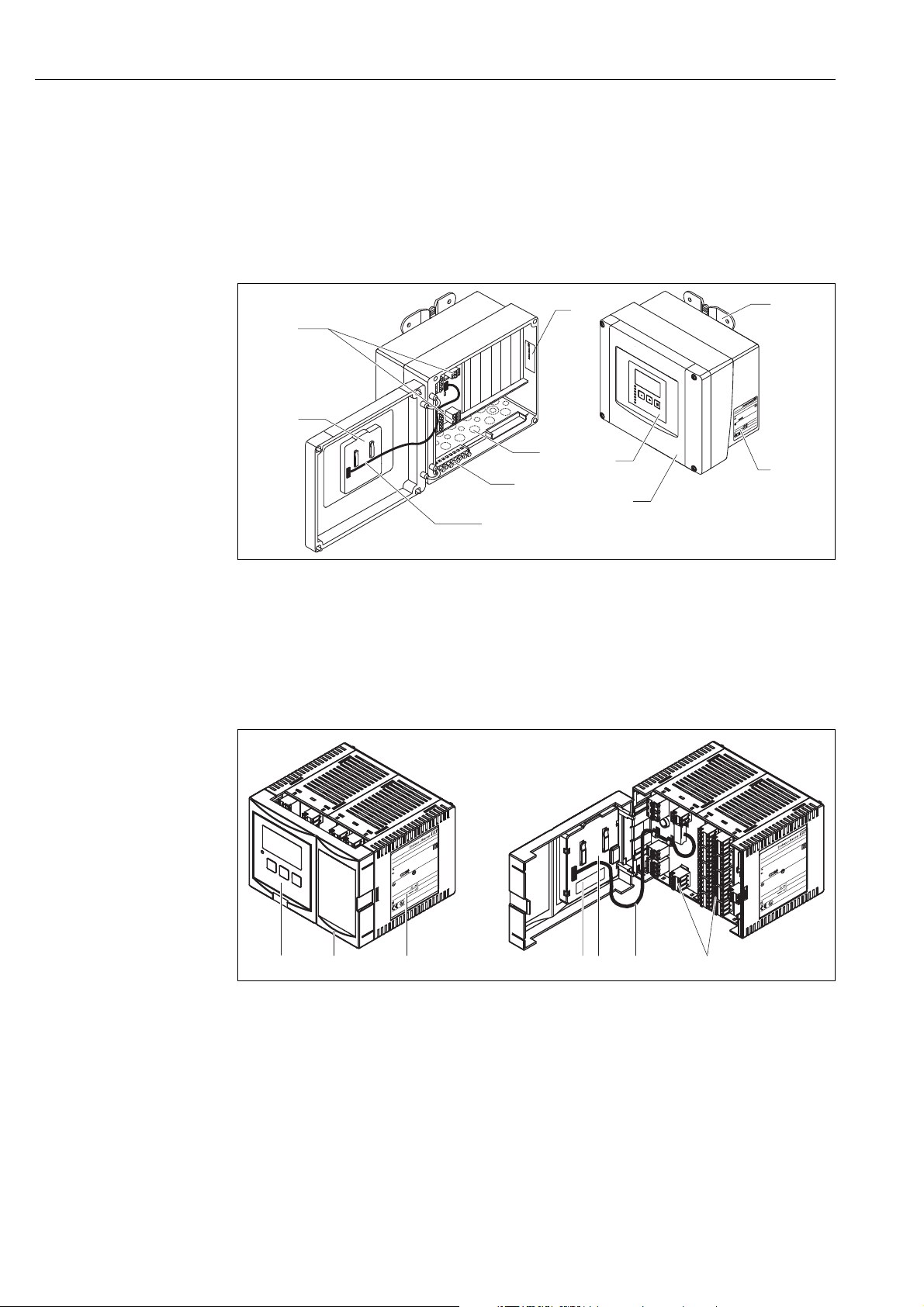
2.1 Parts of the Prosonic S FMU95
2.1.1 FMU95 in the field housing
L00-FMU90xxx-03-00-00 -xx-001
1 Terminals 6 Display and operating module
2 Instrument designation and identification 7 Prestamped openings for cable entries
3 Mounting help 8 Grounding terminals
4 Nameplate 9 Display cable
5 Cover of the terminal compartment 10 Short instructions
2.1.2 FMU95 in the DIN-rail housing
L00-FMU95xxx-03-00-00 -xx-001
1 Display and operating module 5 Display cable
2 Cover of the terminal compartment 6 Short instructions
3 Nameplate 7 Terminals
4 Terminals Instrument designation and identification
6 Endress + Hauser
Page 7
Prosonic S FMU95 Identification
M
a
d
e
inG
e
r
m
a
n
y
D
-
7
9
6
8
9
M
a
u
l
b
u
r
g
P
ro
s
o
n
ic
S
Ta
>
6
0
°C
:
II3D T=xxx°C
IP66/NEMA4X
X
A
x
x
x
F
-
A
Dat./Insp.:
if
m
o
dificatio
n
se
e
sep.
lab
el
X
=
10,5…32 V DC 10W
4…20 mA HART
OrderCode:
Ser.-No.: 5A01090109A
FMU90-J11AB111AA1A
1
2
3
Made in Germany
D-79689 Maulburg
Prosonic S
10,5 … 32 V DC 14W
Profibus DP
Order Code:
Ser.-No.: 5A01090109A
FMU95-J11CBA31A
II 3 D T=xxx°C
IP66 / NEMA4X
XAxxxF-A
if modification
see sep. label
X=
Ta > 60°C :
11
9
8
7
6
5
4
1
2
3
10
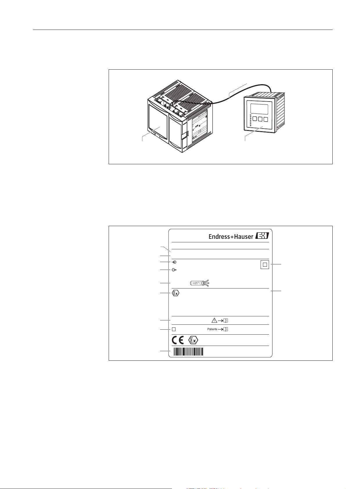
2.1.3 FMU95 with remote display and operating module for cabinet
door and switchboard mounting (96 x 96 mm (3.78 x 3.78 in))
L00-FMU95xxx-03-00-00-xx-002
1 DIN-rail housing without display
2 Remote display and operating module for cabinet mounting
3 The cable (3 m (9.8 ft)) is supplied
2.2 Nameplate (Example)
1 Specification of the electrical protection class (protective insulation)
2 Ingress protection
3 Barcode
4 Marked if a modification nameplate is present
5 Reference to additional safety-relevant documentation
6 Certificate-related data
7 Specification of required temperature resistance of the connection cables
8Output signal
9 Power supply
10 Serial number
11 Order code (as defined by the product structure)
L00-FMU95xxx-18-00-00-xx-001
Endress + Hauser 7
Page 8
Identification Prosonic S FMU95
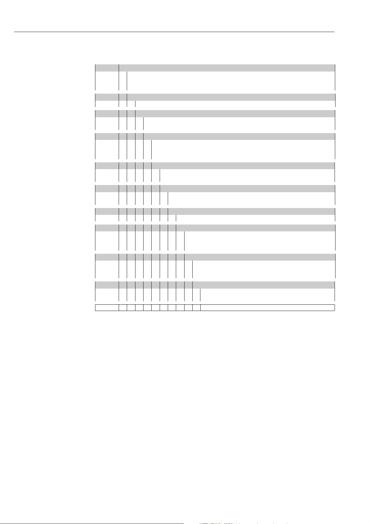
2.3 Product structure
010 Approval
R Non-hazarous area
JATEX II 3D
N CSA General Purpose
020 Application
1Level
030 Housing, material
1 Field mounting PC, IP66 NEMA 4x
2 DIN rail mounting PBT, IP20
040 Operation
C Illuminated display + keypad
E Illuminated display + keypad, 96x96, panel mounting, front IP65
K w/o display, via communication
050 Power supply
A 90-253 VAC
B 10.5-32 VDC
060 Level input
A 5x sensor FDU9x/8x
B 10x sensor FDU9x/8x
080 Output
3PROFIBUS DP
110 Language (*)
1 de, en, nl, fr, es, it, pt
2 de, en, ru, pl, cs
3 en, zh, ja, ko, th, id
120 Additional option
A Basic version
L 5-point linearity protocol only to order with FDU9x sensor +
5-point linearity protocol
995 Marking
1 Tagging (TAG)
2Bus address
FMU95 - complete product designation
(*): meaning of the language code:
cs: Czech; de: German; en: English; es: Spanish; fr: French; id: Bahasa (Indonesia, Malaysia); it:
Italian; ja: Japanese; ko: korean; nl: Dutch; pl: Polish; pt: Portuguese; ru: Russian; th: Thai; zh:
Chinese
8 Endress + Hauser
Page 9

Prosonic S FMU95 Identification
2.4 Scope of delivery
• Instrument according to the version ordered
• Endress+Hauser operating program on the enclosed CD-ROM
• For FMU95-***E*****:
remote display and operating module; retainers; connection cable (3 m (9.8 ft))
• Accessories ä 88
• Approval documentation: if this is not included in the operating manual (Refer to the nameplate
for the names of the safety instructions that apply to your device version.)
• CD-ROM with further documentation, e.g.
– Technical Information
– Operating Instructions
– Description of Instrument Functions
– Slot/Index tables
• Brief operating instructions for quick commissioning: KA01069F
2.5 Certificates and approvals
CE mark, declaration of conformity
The device is designed to meet state-of-the-art safety requirements, has been tested and left the
factory in a condition in which it is safe to operate. The device complies with the applicable
standards and regulations as listed in the EC declaration of conformity and thus complies with the
statutory requirements of the EC directives. Endress+Hauser confirms the successful testing of the
device by affixing to it the CE mark.
2.6 Registered trademarks
PROFIBUS
Registered trademark of the PROFIBUS Trade Organisation, Karlsruhe, Germany
ToF
Registered trademark of the company Endress+Hauser GmbH+Co. KG, Maulburg, Germany
FieldCare
Trademark of Endress+Hauser Process Solutions AG
®
®
®
Endress + Hauser 9
Page 10
Installation Prosonic S FMU95
215 (8.46)
180 (7.09)
150 (5.91)
15 (0.59)
170 (6.69)
190 (7.48)
80
(3.15)
100
(3.94)
ø6.5 (0.26)
10 (0.39)
A
B
»1,6 kg (3.53 lbs)
153 (6.02)
C
³55 (2.17)
³55 (2.17)
3 Installation
3.1 Incoming acceptance, transport, storage
3.1.1 Incoming acceptance
Check the packing and contents for any signs of damage.
Check the shipment, make sure nothing is missing and that the scope of supply matches your order.
3.1.2 Transport, storage
Pack the measuring instrument so that it is protected against impacts for storage and transport. The
original packing material provides the optimum protection for this.
Permissible storage temperature: -40 to +60 °C (-40 to +140 °F)
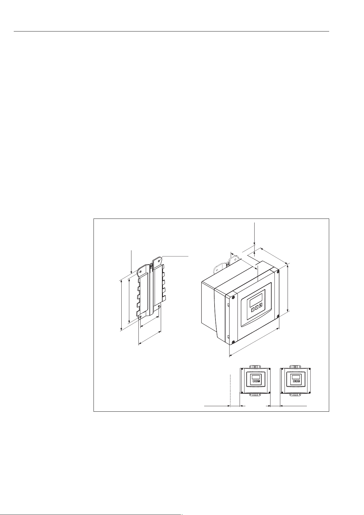
3.2 Mounting the field housing
3.2.1 Dimensions of the field housing
Dimensions in mm (in)
A Mounting help (supplied); can also be used as drilling template
B Field housing
C Minimum mounting distance
The dimensions of the field housing are the same for all instrument versions.
To open the housing, a minimum mounting distance of 55 mm (2.17 in) is required on the left.
L00-FMU90xxx-06-00-00 -xx-001
10 Endress + Hauser
Page 11
Prosonic S FMU95 Installation
1.
2.
3.
4.
1
3.2.2 Installation conditions
Weather protection
In order to avoid excessive sunlight exposure, the instrument should be mounted in a position
which is protected against direct sunlight or a protection cover should be applied ( ä 88,
"Accessories").
Overvoltage protection
In order to protect the Prosonic against overvoltages (especially if mounted outdoors), connection
of an overvoltage protection is recommended ( ä 88, "Accessories").
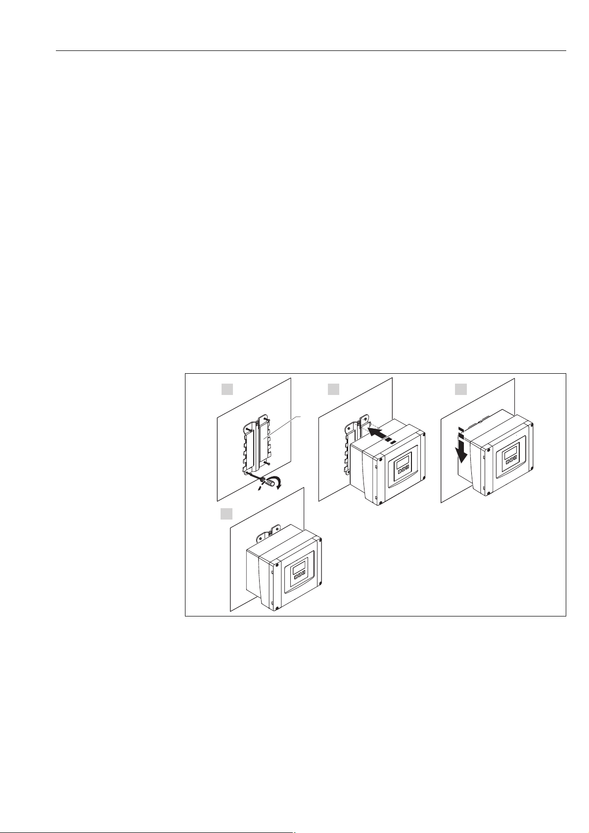
Wall mounting
A mounting help for wall mounting is supplied. It also serves as drilling template. The mounting
help should be mounted on a flat surface and may not become distorted.
Pipe mounting
A mounting plate is available for mounting of the field housing to 1" to 2" pipes ( ä 88,
"Accessories").
3.2.3 Installation
1 Wall mounting with mounting help
L00-FMU90xxx-17-00-00-xx-003
Endress + Hauser 11
Page 12
Installation Prosonic S FMU95
150 (5.91)
104 (4.09)
140 (5.51)
EN 60715
TH 35x7.5/15
(1.4x0.3/0.6)
35 (1.38)
»0,7 kg (1.54 lbs)
42 (1.65)
A
B
1.
2.
1.
2.
EN 60715
TH 35x7.5/15
(1.4x0.3/0.6)
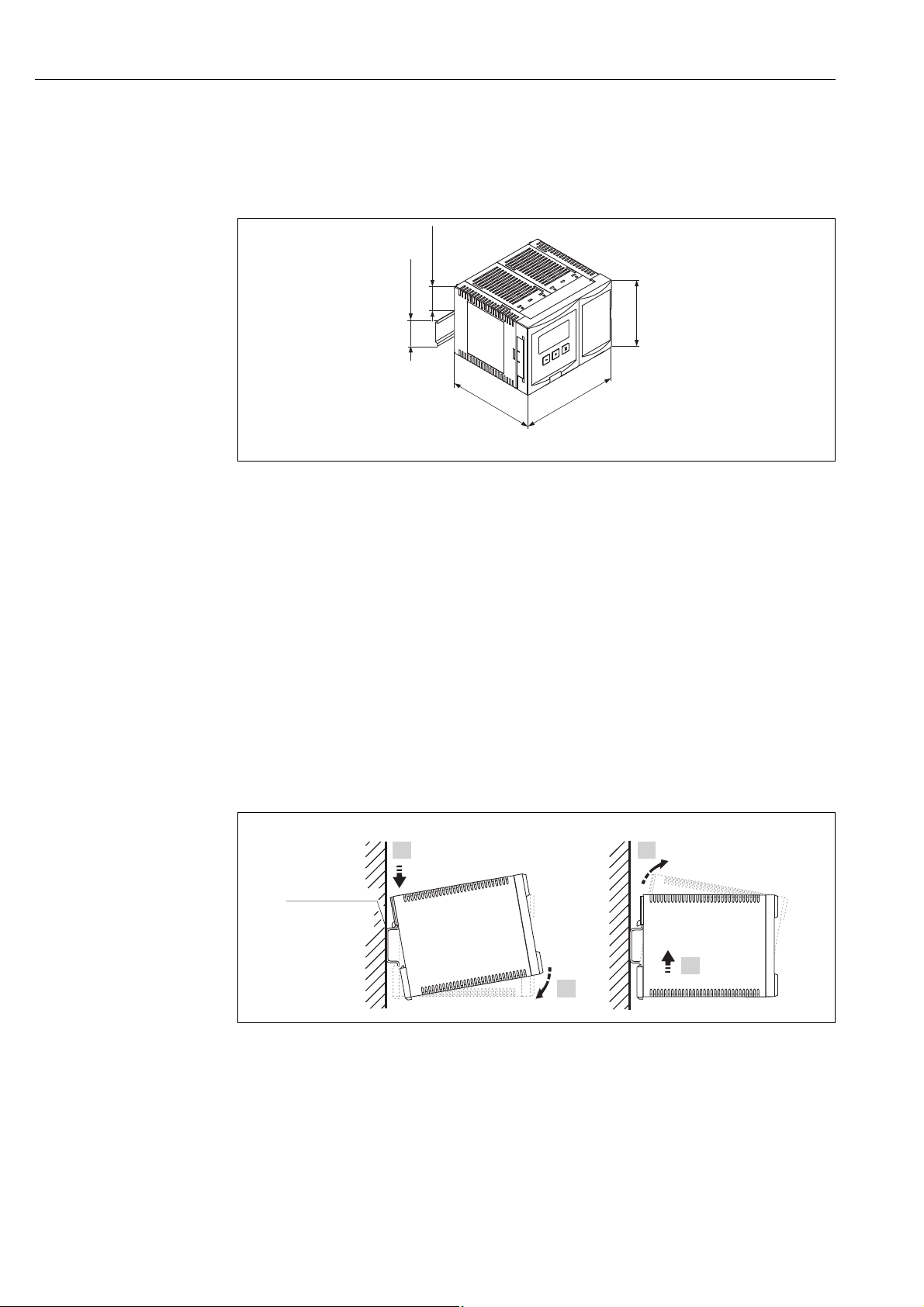
3.3 Mounting the DIN-rail housing
3.3.1 Dimensions of the DIN-rail housing
L00-FMU90xxx-06-00-00 -xx-005
Dimensions in mm (in)
3.3.2 Installation conditions
• The DIN-rail housing must be mounted outside hazardous areas in a cabinet.
• The housing is mounted on a DIN rail EN 60715 TH 35x7.5 or TH 37x15.
• Do not install the instrument in the vicinity of high-voltage lines, motor lines, contactors or
frequency converters. The installation regulations for high-voltage lines, motor lines, contactors
or frequency converters must be observed.
• To ensure easy mounting and opening of the housing, a distance of approx. 10 mm (0.39 in)
should be kept between the instruments.
• In order to avoid interference signals, the sensor cables must not be laid parallel to high voltage
or electric power lines.
• The cables may not be laid in the proximity to frequnecy converters.
3.3.3 Mounting
L00-FMU90xxx-17-00-00 -xx-001
A Attaching the instrument to the rail
B Detaching the instrument from the rail
12 Endress + Hauser
Page 13
Prosonic S FMU95 Installation
96
55
max. 6
92
min. 11
~0,5 kg (1.10 lbs)
(0.43)
(3.62)
(0.24)
(3.78)
(2.17)
mm (in)
1.
3.
4.
2.
3.4 Mounting the remote display and operating module
3.4.1 Scope of delivery
If the Prosonic S is ordered with the display for cabinet door mounting, the following is contained
in the scope of delivery:
• Display and operating module, 96 x 96 mm (3.78 x 3.78 in)
• 4 retainers (with nuts and screws)
• Connection cable (3 m (9.8 ft)) for connection to the transmitter
(preassembled with suitable plugs).
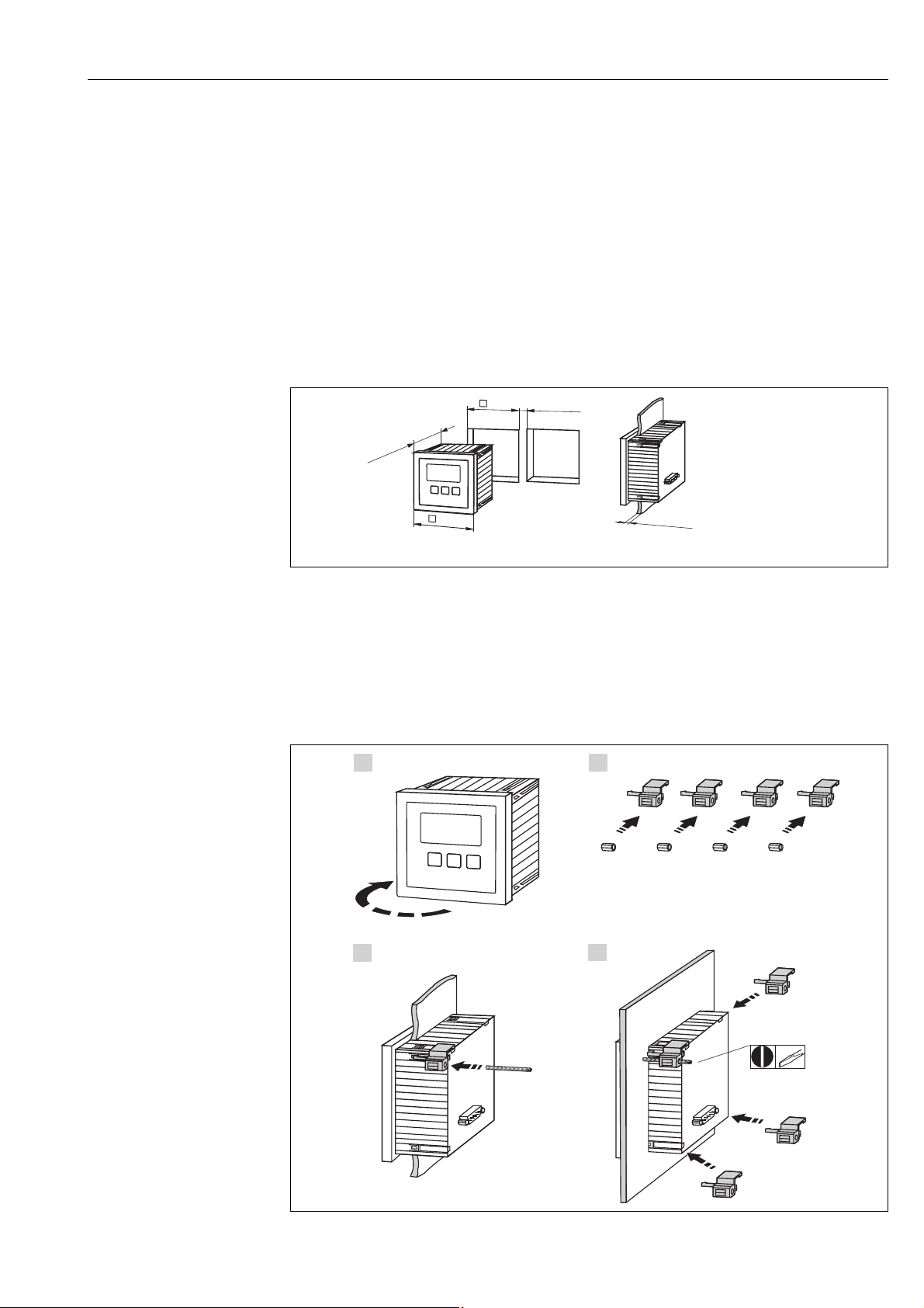
3.4.2 Dimensions of the separate display and operating module
L00-FMU90xxx-06-00-00-xx-004
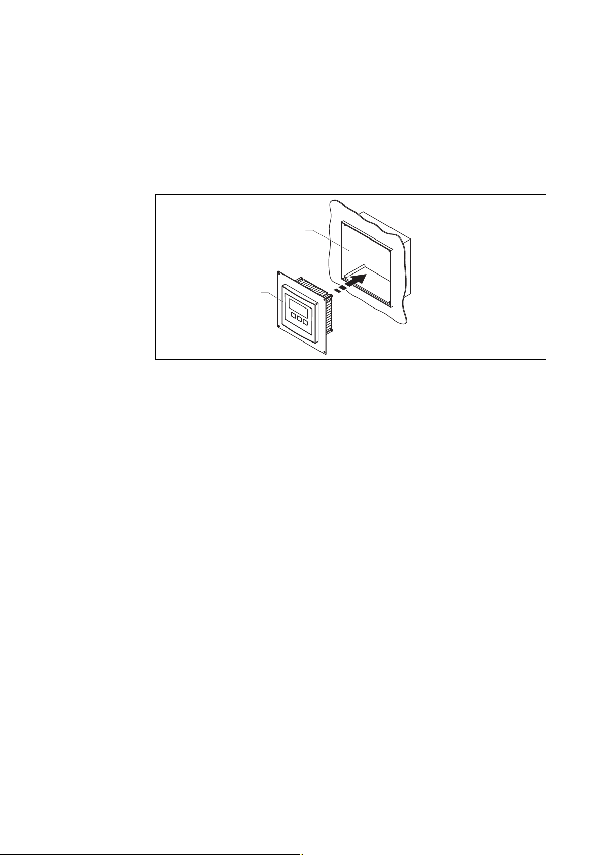
3.4.3 Mounting
1. Cut an opening of 92 x 92 mm (3.62 x 3.62 in) into the intended mounting position (e.g.
cabinet door).
2. Insert the remote display module into the opening and fix the retainers as shown in the
following figure:
Endress + Hauser 13
L00-FMU90xxx-17-00-00-xx-002
Page 14
Installation Prosonic S FMU95
1
2
3.4.4 Adaption plate
If an opening of 138 x 138 mm and the remote display of the Prosonic FMU860/861/862 are
already present, you can use the adaption plate (Order Code: 52027441, ( ä 88, "Accessories").
It is inserted into the remote display of the FMU860/861/862.
!
Note!
The adapter plate is mounted directly in the housing of the old remote display of the FMU86x series.
The housing of the remote display of the FMU86x is the holder for the adapter plate and the new
remote display of the FMU90/FMU95 in the format 96 x 96 mm (3.78 x 3.78 in).
L00-FMU90xxx-06-00-00 -xx-006
1 Remote display of the FMU90 with adaption plate
2 Opening of the remote display of the FMU860/861/862
3.5 Mounting of the sensors
Information on the mounting of the sensors can be found in the following documents:
• Technical Information TI00189F (for FDU8x)
• Technical Information TI00396F (for FDU9x)
These documents are supplied with the sensors.
3.6 Installation check
After installing the device, carry out the following checks:
• Is the device damaged (visual inspection)?
• Does the device correspond to the meausring point specifications such as process temperature,
process pressure, ambient temperature, measuring range etc?
• If available: Are the measuring point number and labelling correct?
• Is the instrument sufficiently protected against rainfall and direct sunlight?
• For the field housing: Are the cable glands tightened correctly?
• Is the instrument securely mounted to the DIN rail or the mounting help (visual inspection)?
• For the field housing: Are the screws of the terminal compartment cover securely tightened
(visual inspection)?
14 Endress + Hauser
Page 15
Prosonic S FMU95 Wiring
1.
2.
3.
1.
2.
4 Wiring
#
Warning!
The instrument may only be installed if the supply voltage is switched off.
4.1 Terminal compartment
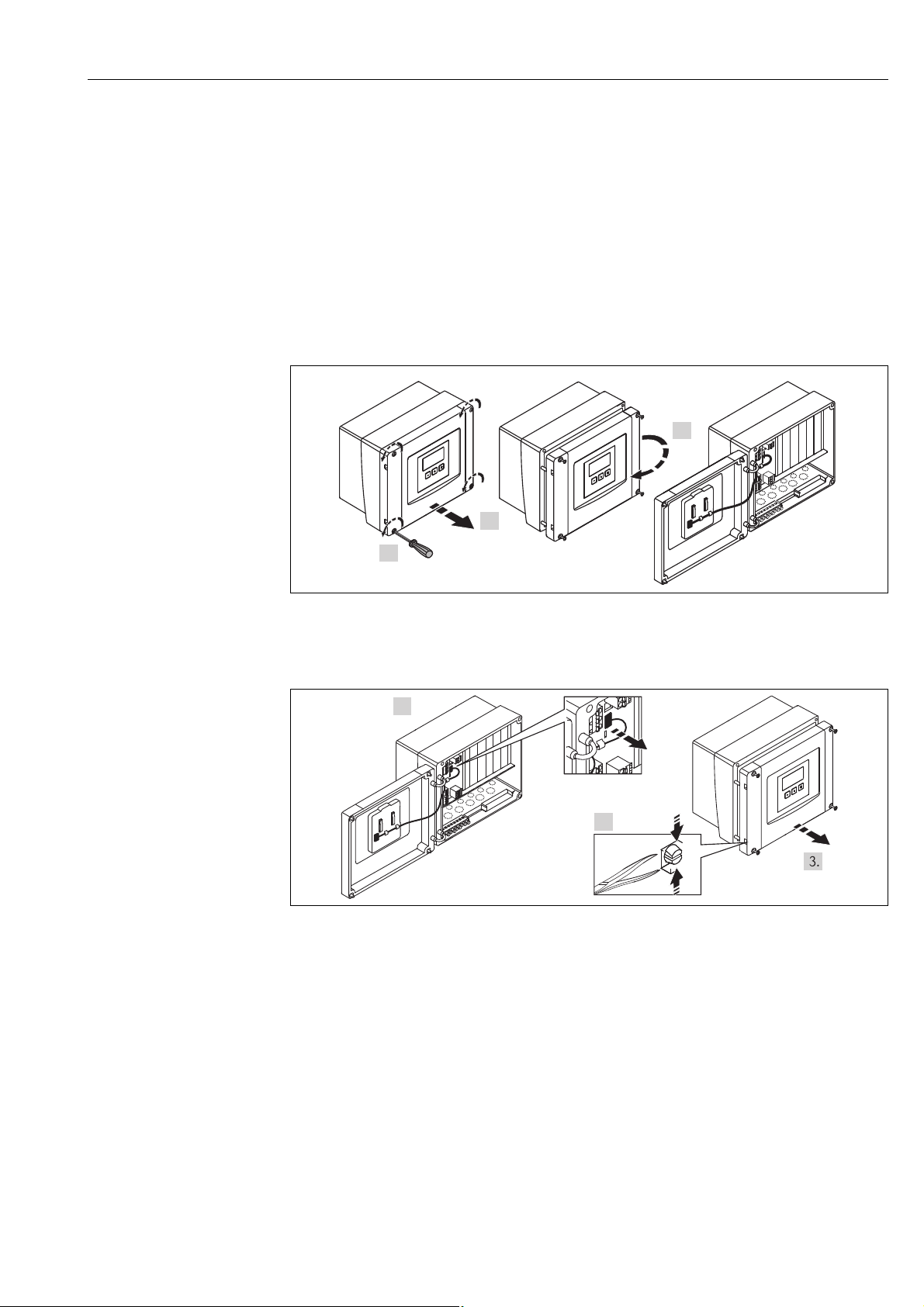
4.1.1 Terminal compartment of the field housing
The field housing has a separate terminal compartment. It can be opened after loosening the four
screws of the lid.
L00-FMU90xxx-04-00-00-xx-002
For easier wiring, the lid can be completely removed by unplugging the display plug (1) and loosening the hinges (2):
L00-FMU90xxx-04-00-00-xx-009
4.1.2 Cable entries of the field housing
The following openings for cable entries are prestamped on the bottom of the housing :
• M20x1,5 (10 openings)
• M16x1,5 (5 openings)
• M25x1,5 (1 opening)
The required number and types of cable entries depend on the application at hand.
The prestamped openings can be removed by a suitable tool (e.g. knife or boring bit) or by punching
them out cautiously.
Endress + Hauser 15
Page 16
Wiring Prosonic S FMU95
1.
2.
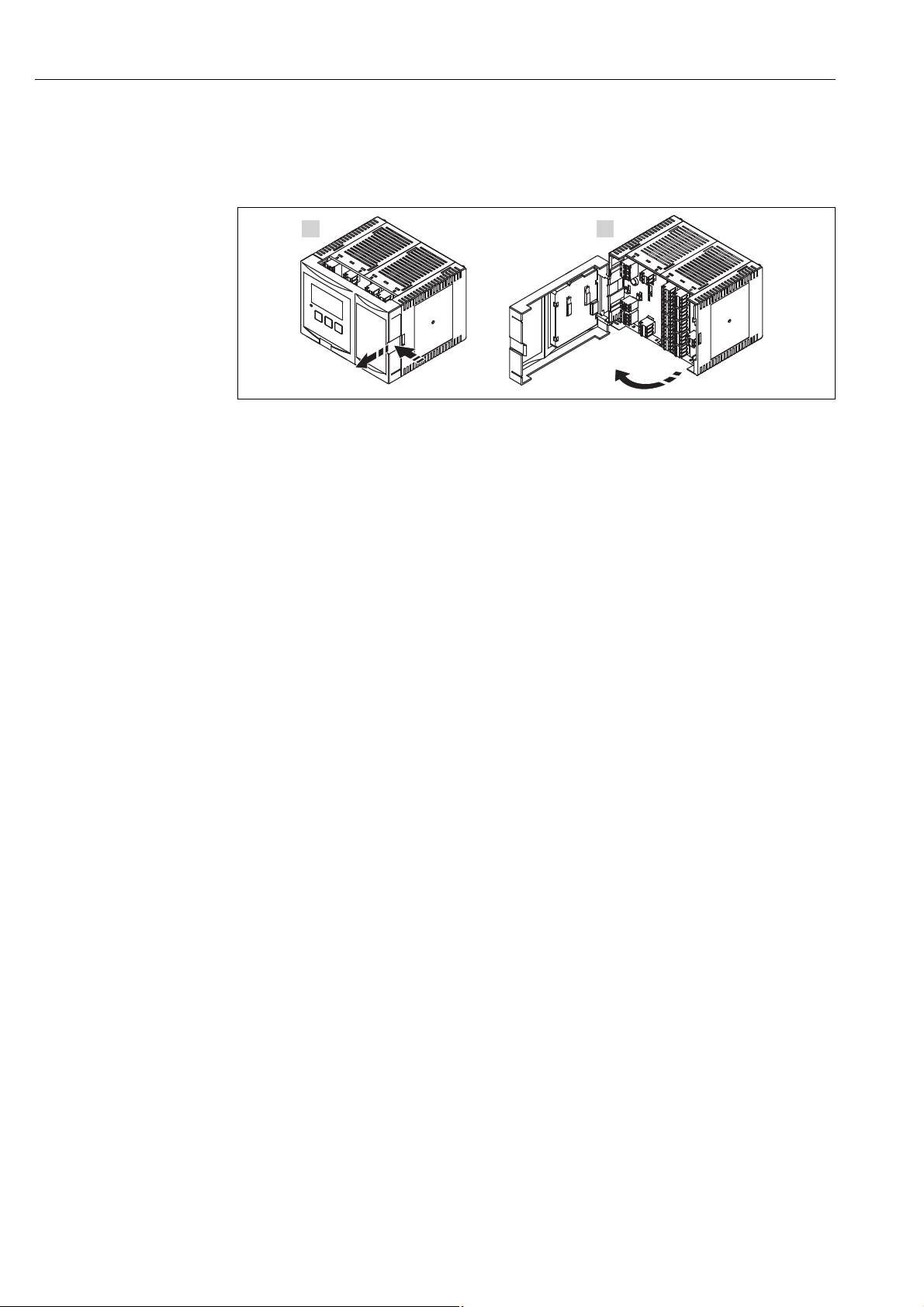
4.1.3 Terminal compartment of the DIN-rail housing
Single instrument
L00-FMU95xxx-04-00-00 -xx-005
The catch can be unlocked by slightly pressing onto the clip. Then, the cover of the terminal
compartment can be opened.
16 Endress + Hauser
Page 17
Prosonic S FMU95 Wiring
1.
2.
3.
1.
2.
3.
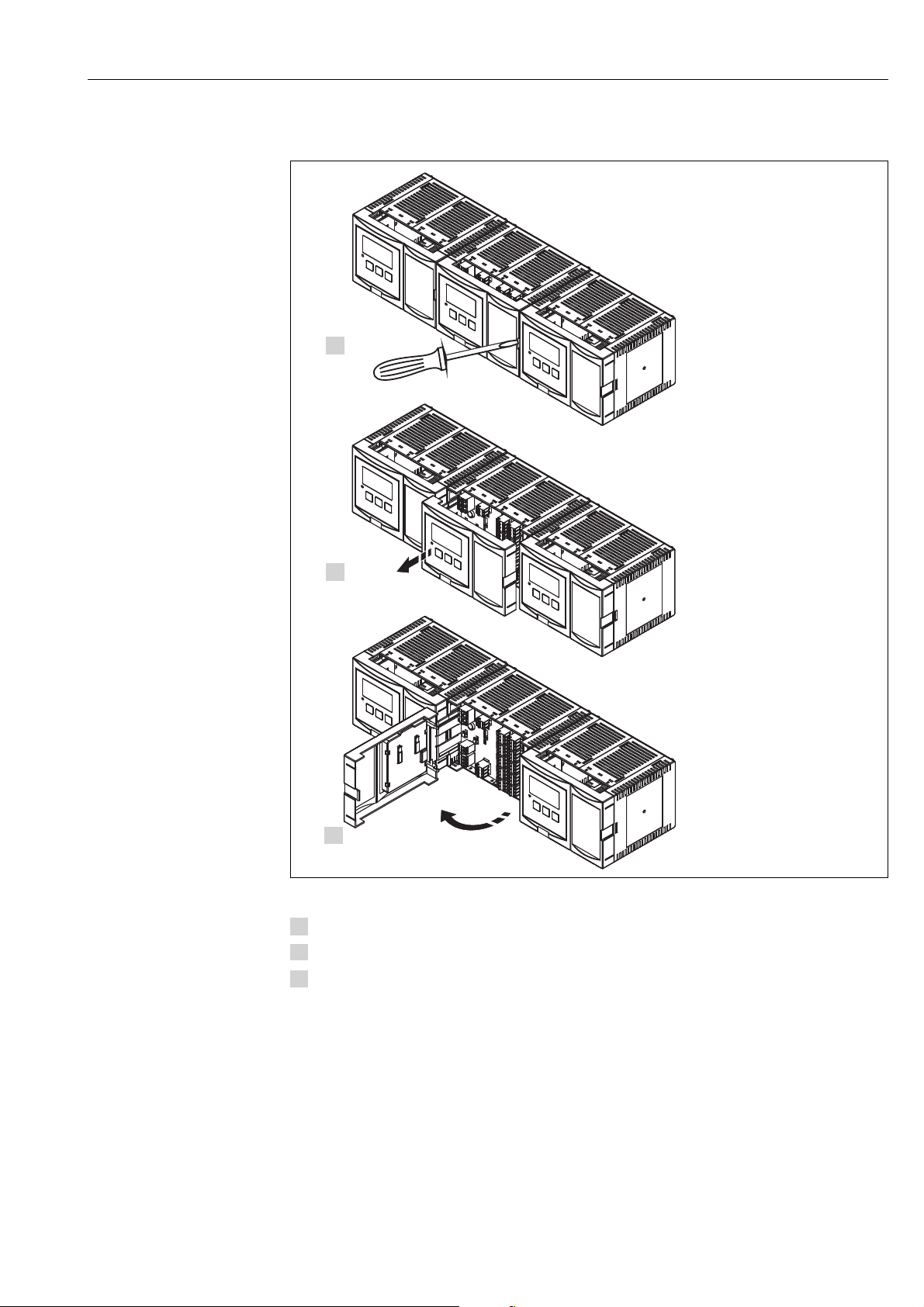
Several instruments mounted side by side
L00-FMU95KAx-04-00-00-xx-005
Open the catch of the cover (e.g. by a screwdriver).
Pull the cover out by approx. 20 mm (0.79 in) .
The cover can now be opened.
!
Note!
• The cables can be inserted into the housing from above or from below.
• If the instruments are mounted next to each other and if the sensor cables run in parallel, the
synchronization terminals (39 and 40) must be interconnected ( ä 18 "Terminal assignment"
und ä 24 "Synchronization line").
Endress + Hauser 17
Page 18
Wiring Prosonic S FMU95
Address
Term.
DP
off
on
off
on
SW
HW
1
2
3
4
5
6
7
8
1
2
3
4
A(N)
66
B(P)
65
Display
POWER
Sync
Fuse
40
39
Service
32
1
11
10
9
1
FDU-Sensor
YE BK RD
14
13
12
2
YE BK RD
17
16
15
3
YE BK RD
20
19
18
4
YE BK RD
23
22
21
5
YE BK RD
26
25
24
6
YE BK RD
29
28
27
7
YE BK RD
32
31
30
8
YE BK RD
35
34
33
9
YE BK RD
38
37
36
10
YE BK RD
FDU-Sensor
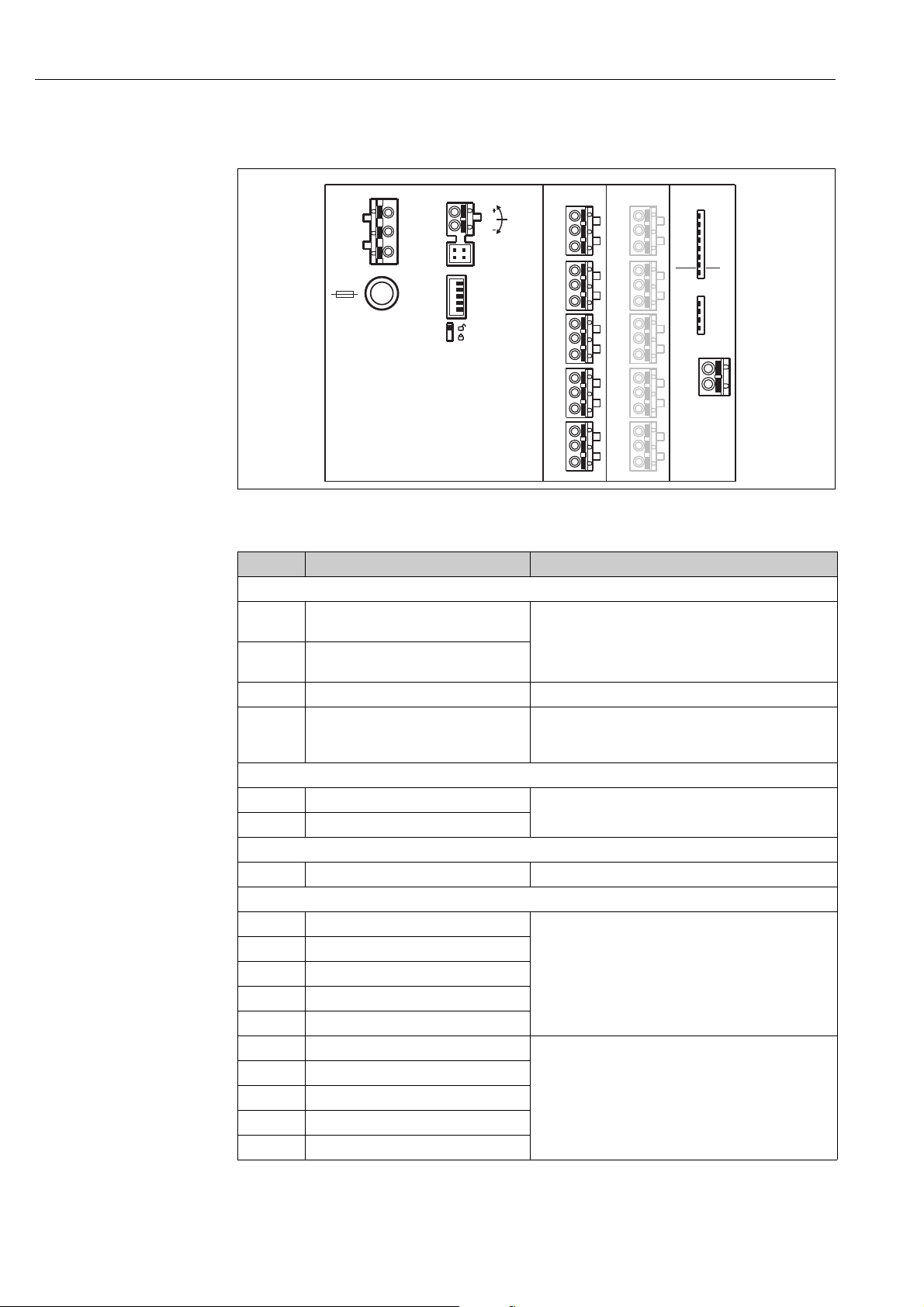
4.2 Terminal assignment
L00-FMU90xxx-04-00-00 -xx-001
Terminals of the Prosonic S FMU95; the terminals depicted in grey are not present in every instrument version.
Terminals Meaning Remarks
Auxiliary energy
1
2
•L (for AC version)
•L+ (for DC version)
•N (for AC version)
•L- (for DC version)
depending on instrument version:
• 90 ... 253 V
• 10,5 ... 32 V
AC
DC
3 Potential equalization
depending on instrument version:
Fuse
• 400 mA T (for AC)
•2 A T (for DC)
Bus communication
65 PROFIBUS A (RxT/TxD - N)
66 PROFIBUS B (RxT/TxD - P)
Synchronization
39, 40 Synchronization ä 24, "Synchronization line"
Level inputs
09,10,11 Sensor 1 (FDU8x/9x)
12, 13, 14 Sensor 2 (FDU8x/9x)
15, 16, 17 Sensor 3 (FDU8x/9x)
18, 19, 20 Sensor 4 (FDU8x/9x)
18 Endress + Hauser
21, 22, 23 Sensor 5 (FDU8x/9x)
24, 25, 26 Sensor 6 (FDU8x/9x)
27, 28, 29 Sensor 7 (FDU8x/9x)
30, 31, 32 Sensor 8 (FDU8x/9x)
33, 34, 35 Sensor 9 (FDU8x/9x)
36, 37, 38 Sensor 10 (FDU8x/9x)
YE: yellow strand
BK: black strand
RD: red strand
only available for the version with 10 sensor inputs
YE: yellow strand
BK: black strand
RD: red strand
Page 19
Prosonic S FMU95 Wiring
#
!
#
Warning!
When using the public supply mains, an easily accesible power switch must be installed in the
proximity of the device. The power switch must be marked as a disconnector for the device (IEC/
EN 61010)
Note!
• In order to avoid interference signals, the sensor cables should not be laid parallel to high voltage
or electric power lines.
• The cables may not be laid in the proximity to frequnecy converters.
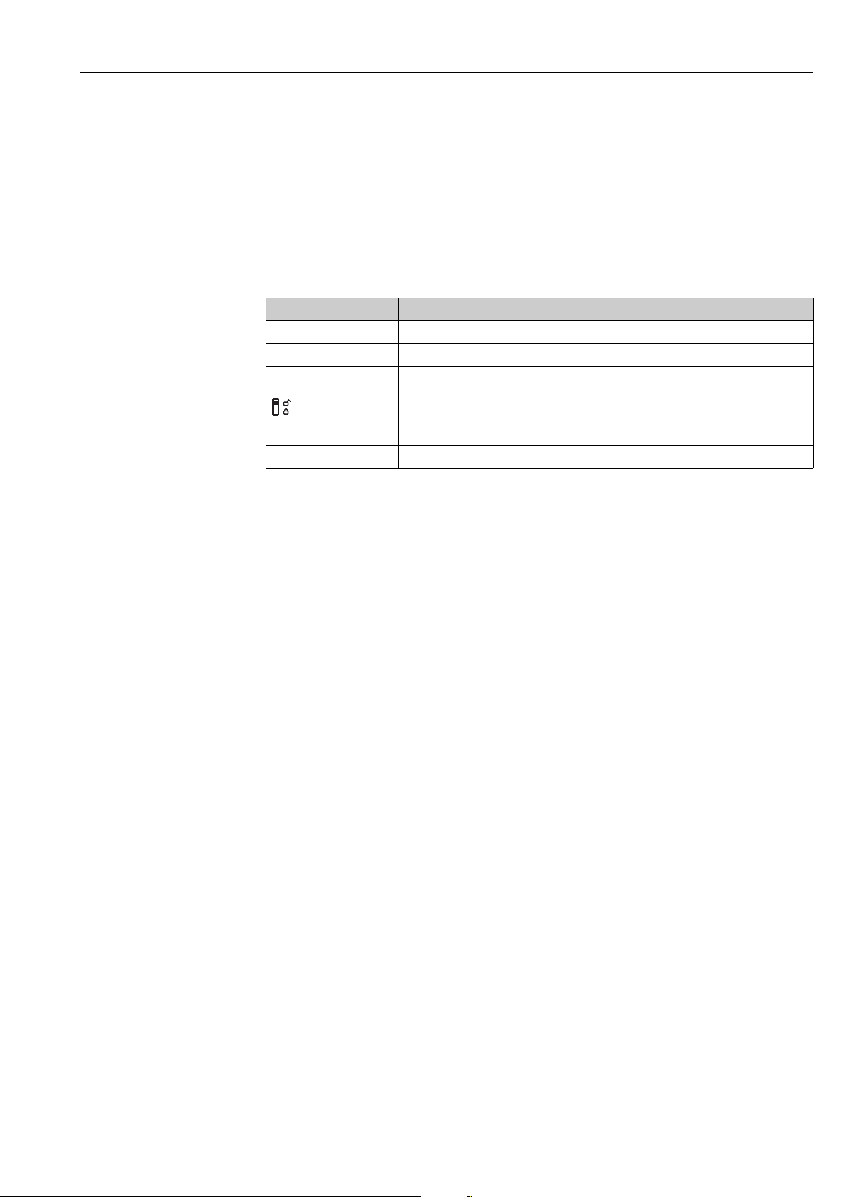
Additional elements on the terminal areas
Designation Meaning/Remarks
Fuse Fuse: 2 A T /DC or 400 mA T/AC
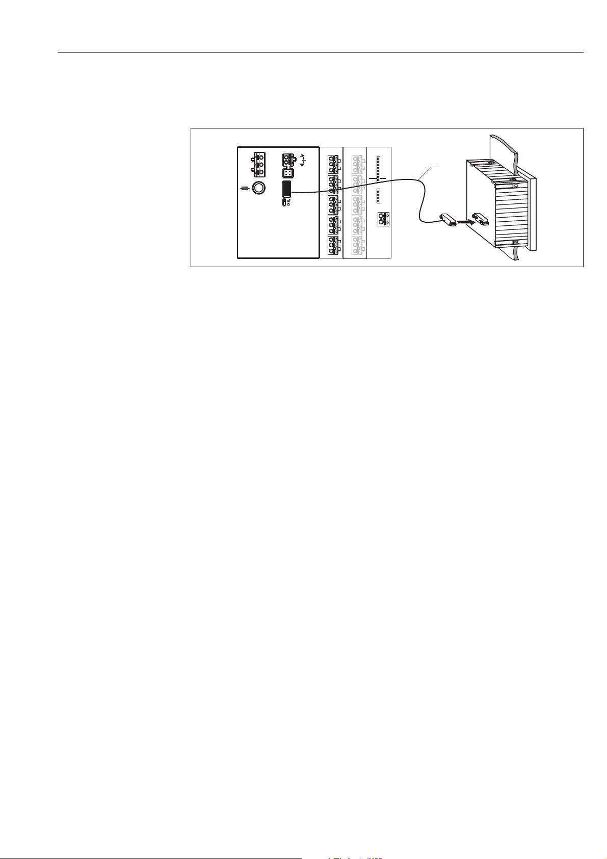
Display Connection of the display or the remote display and operating module ( ä 25)
Service Service interface for connection of a PC/Notebook via Commubox FXA291 ( ä 29)
Locking switch, ä 47 "Unlock configuration"
Term. Bus termination
Address Bus address
Warning!
On wiring, the supply voltage must be switched off.
Endress + Hauser 19
Page 20

Wiring Prosonic S FMU95
4.3 Connection to a PROFIBIS DP network
!
Note!
Information on the structure of a PROFIBUS DP network can be found in the Operating Instructions
BA 034S ("PROFIBUS PA/DP - Guidelines for planning and commissioning".
4.3.1 Cable specifications
For transmission rates up to 12 MBit/s cable type A according to EN 50170 can be used. The
specifications are summarized in the following table:
Terminator 135 to 165 at a measuring frequency from 3 MHz to 20 MHz
Cable capacitance < 30pF per meter
Core cross-section > 0.34 mm
Cable type twisted pairs, 1x2, 2x2 or 1x4 core
Loop resistance 110 per km
Siganl attenuation max. 9 dB over the entire length of the segment
Screening woven copper sheath or woven sheath and foil sheath
Pre-assembled cables are available from Endress+Hauser ( ä 88, "Accessories").
2
, corresponds to AWG 22
4.3.2 T-box
It is recommended to connect the Prosonic S to the bus by a T-box.
Suitable T-boxes are available from Endress+Hauser ( ä 88, "Accessories").
4.3.3 Spurs
Spurs are the connection cables from the bus to the instrument.
Caution!
"
Obeserve the following:
• Total length of all spurs < 6.6 m (22 ft), (for a maximum baudrate of 1.5 MBit/s)
• For baud rates > 1.5 MBit/s no spurs should be used. A spur is the cable between the connector
and the bus driver in the field instrument. Plant experience has shown that much care should be
taken when planning the spurs. It can not be guaranteed that the sum of all spurs at 1.5 MBit/s
may be 6.6 m (22 ft). The actual arrangement of the field intruments has a great influence on this.
Therefore it is strictly recommended to use no spurs for transmission rates > 1.5 MBit/s.
• If usage of spurs can not be avoided, these may not have a bus bus termination.
20 Endress + Hauser
Page 21
Prosonic S FMU95 Wiring
YE
BK
RD
FDU90/91/92
(FDU80/80F/81/81F/82)
BK
YE
RD
(1)
YE
BK
RD
FDU91F/93/95/96
(FDU83/84/85/86)
BK
YE
RD
GNYE
(2)
(3)
FMU95
(1)
(2)
(3)
FMU95
(A)
max.
300 m
YE
BK
RD
FDU91F/93/95/96
(FDU83/84/85/86)
BK
YE
RD
GNYE
(1)
FMU95
(B)
max.
30 m
max.
300 m
max.
30 m
FDU90/91/92
(FDU80/80F/81/81F/82)
FDU91F/93/95/96
(FDU83/84/85/86)
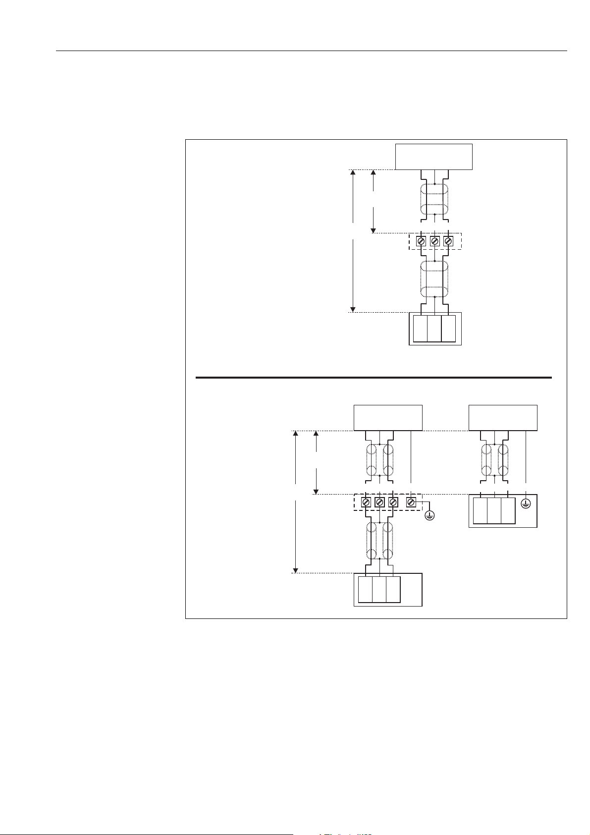
4.4 Sensor connection
4.4.1 Connection diagram
(A): grounding at the terminal box;
(B): grounding at the transmitter FMU90;
(1): Screen of the sensor cable;
(2): Terminal box;
(3): Screen of the extension cable;
Colours of the strands: YE = yellow; BK = black; RD = red; GNYE = green-yellow
L00-FMU95xxx-04-00-00-xx-004
Endress + Hauser 21
Page 22

Wiring Prosonic S FMU95
4.4.2 Connection hints
Caution!
"
• In order to avoid interference signals, the sensor cables should not be laid parallel to high voltage
electric power lines. The cables may not be laid in the proximity to frequency converters.
• The cable screen serves as a return cable and must be connected to the transmitter without any
electrical break. With the pre-assembled cables, the screen ends in a black strand (BK). With the
extension cable, the screen must be twisted together and connected to the "BK" terminal.
#
Warning!
• The sensors FDU83, FDU84, FDU85 and FDU86 with an ATEX, FM or CSA certificate are not
certified for connection to the FMU90 transmitter.
• for the sensors FDU91F/93/95/96 and FDU83/84/85/86:
The ground lead (GNYE) must be connected to the local potential equalization after a maximum
distance of 30 m (98 ft). This can be done
– either at the terminal box
– or at the transmitter FMU90 or in the cabinet (if the distance to the sensor does not exceed
30 m (98 ft).
!
"
Note!
For easier mounting it is advisable to use the sensors FDU90/91/92 and FDU80/80F/81/81F/82
with a maximum cable length of 30 m (98 ft) as well. For longer distances an extension cable with
a terminal box should be used.
4.4.3 Extension cables for the sensors
For distances up to 30 m (98 ft) the sensor can be directly connected by the sensor cable. For longer
distances, it is recommended to use an extension cable. The extension cable is connected via a
terminal box. The total length (sensor cable + extension cable) may be up to 300 m (984 ft).
Caution!
If the terminal box is installed in explosion hazardous areas, all applicable national guidelines must
be observed.
Suitable extension cables can be obtained from Endress+Hauser ( ä 88, "Accessories")
Alternatively, cables with the following properties can be used:
• Number of cores according to the connection diagram (see above)
• braided wire screen for the yellow (YE) and red (RD) core (no foil screen)
• Length: up to 300 m (984 ft), sensor cable + extension cable
• Cross section: 0.75 mm
•up to 8 per core
• max. 60 nF (between core and screen)
• for FDU91F/93/95/96 and FDU 83/84/85/86:
The earth lead must not be within the screening.
2
to 2.5 mm2 (18 to 14 AWG)
22 Endress + Hauser
Page 23
Prosonic S FMU95 Wiring
FDU90/91/92
(FDU80/80F/81/81F/82)
FDU91F/93/95/96
(FDU83/84/85/86)
RD
BK
YE
RD
BK
YE
GNYE
1. 1.
RD
YE
GNYE
RD
YE
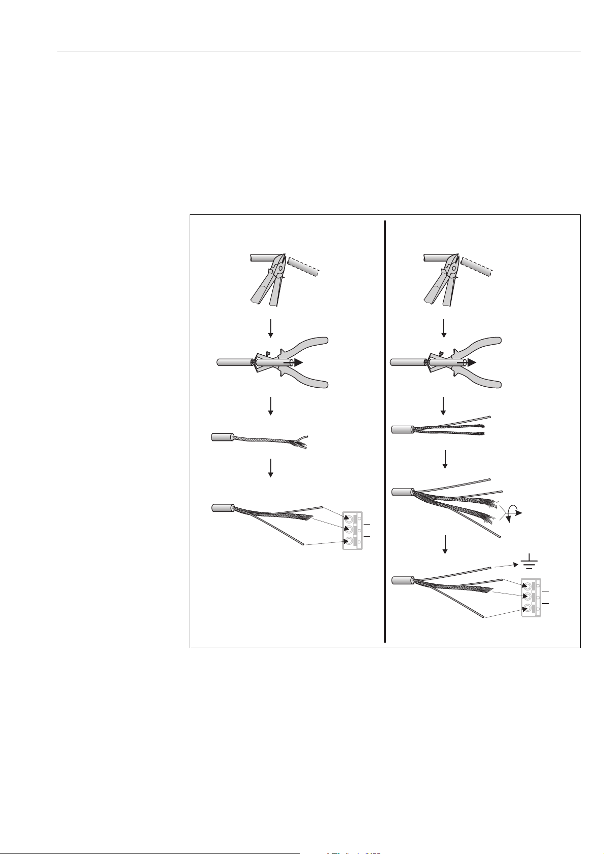
4.5 Shortening the sensor cable
If required, the sensor cable can be shortened. Please note:
• Do not damage the cores when removing the insulation.
• The cable is shielded by a metallic braiding. This shielding serves as a return cable and
corresponds to the black (BK) strand of the unshortened cable. After shortening the cable, loosen
the metallic braiding, twist it together securely and connect it to the "BK" terminal.
Caution!
"
The protective earth conductor (GNYE), which is present in some of the sensor cables, may not be
electrically connected to the cable shield.
Endress + Hauser 23
Colours of the strands: YE = yellow; BK = black; RD = red; GNYE = green-yellow
L00-FMU95xxx-04-00-00-xx-011
Page 24
Wiring Prosonic S FMU95
Prosonic S
FMU90/95
39 40
1
23
20
……
FMU90 FMU90 FMU90
Prosonic S
FMU90/95
39 40
Prosonic S
FMU90/95
39 40
Prosonic S
FMU90/95
39 40
Prosonic
FMU860/861/862
63 64
1
2
10
……
FMU90
VH
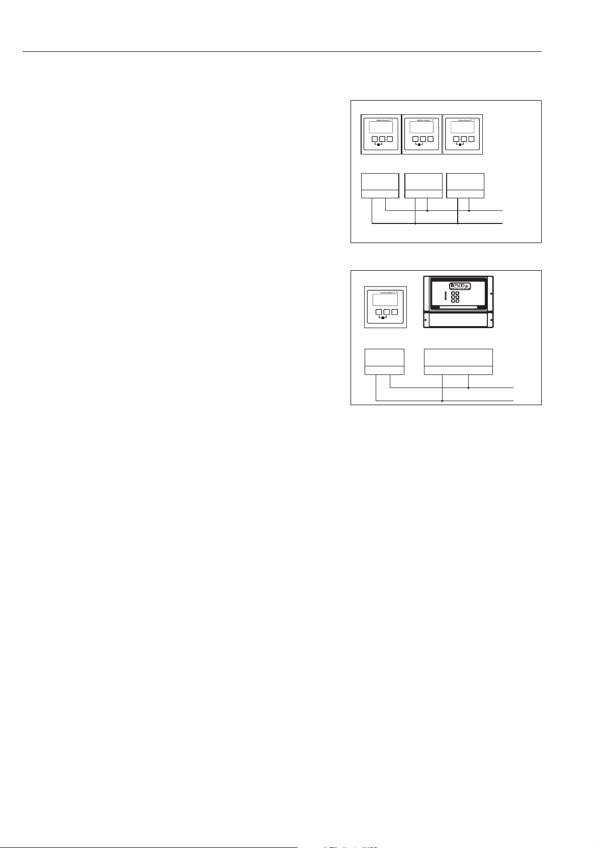
4.6 Synchronization line
• If wiring several Prosonic S (FMU90/FMU95)
which are mounted in a common cabinet and
if the sensor cables run in parallel, the
synchronization terminals (39 and 40) must
be interconnected.
• Up to 20 instruments can be synchronized in
this way.
• The synchronization causes the evaluation
units FMU9x to send the pulses
simultaneously. Only after all sensors have
received their signal, new simultaneous pulses
are sent. This prevents pulses in the sensor
cable of one sensor from influencing the
received signal on the cable of a different
sensor.
• If there are more than 20 instruments, groups
must be formed, each containing a maximum
of 20 instruments. For the instruments within
each group, the sensor cables may run in
parallel. The sensor cables of different groups
must be seperated from each other.
• Usual commercial screened cable can be used
for synchronization
– max. length: 10 m (33 ft) between the
individual instruments
– cross section: 2 x (0.75 to 2.5 mm
2
(18 to 14 AWG))
– for lengths up to 1 m (3.3 ft), an unscreened
cable can be used; for lenghts exceeding
1 m (3.3 ft), screening is required. The
screen must be connected to ground
• Instruments of the Prosonic FMU86x family
can be connected to the synchronization line
as well. In this case a maximum of 10
instruments can be connected to each
synchronisation line.
L00-FMU90xxx-04-00-00 -xx-004
L00-FMU90xxx-04-00-00 -xx-017
24 Endress + Hauser
Page 25
Prosonic S FMU95 Wiring
Address
Term.
DP
off
on
off
on
SW
HW
1
2
3
4
5
6
7
8
1
2
3
4
A(N)
66
B(P)
65
Display
POWER
Sync
Fuse
40
39
Service
32
1
11
10
9
1
FDU-Sensor
YE BK RD
14
13
12
2
YE BK RD
17
16
15
3
YE BK RD
20
19
18
4
YE BK RD
23
22
21
5
YE BK RD
26
25
24
6
YE BK RD
29
28
27
7
YE BK RD
32
31
30
8
YE BK RD
35
34
33
9
YE BK RD
38
37
36
10
YE BK RD
FDU-Sensor
1
4.7 Connection of the separate display and operating
module
L00-FMU95xxx-04-00-00-xx-008
1 Connection of the display plug with the cable (3 m (9.8 ft))
For the version of the Prosonic S with a separate display for panel mounting, a pre-assembled
connecting cable (3 m (9.8 ft)) is supplied. The cable must be connected to the display plug of the
Prosonic S.
!
Note!
Minimum diameter for cable bushing: 20 mm (0.79 in).
Endress + Hauser 25
Page 26
Wiring Prosonic S FMU95
1
90 … 253 VAC
10,5 … 32 VDC
NLPE
FDU91F/93/95/96
(FDU83/84/85/86)
1
FMU95
Address
Term.
DP
off
on
off
on
SW
HW
1
2
3
4
5
6
7
8
1
2
3
4
A(N)
66
B(P)
65
Display
POWER
Sync
Fuse
40
39
Service
32
1
11
10
9
1
FDU-Sensor
YE BK RD
14
13
12
2
YE BK RD
17
16
15
3
YE BK RD
20
19
18
4
YE BK RD
23
22
21
5
YE BK RD
26
25
24
6
YE BK RD
29
28
27
7
YE BK RD
32
31
30
8
YE BK RD
35
34
33
9
YE BK RD
38
37
36
10
YE BK RD
FDU-Sensor
GNYE
FDU91F/93/95/96
(FDU83/84/85/86)
GNYE
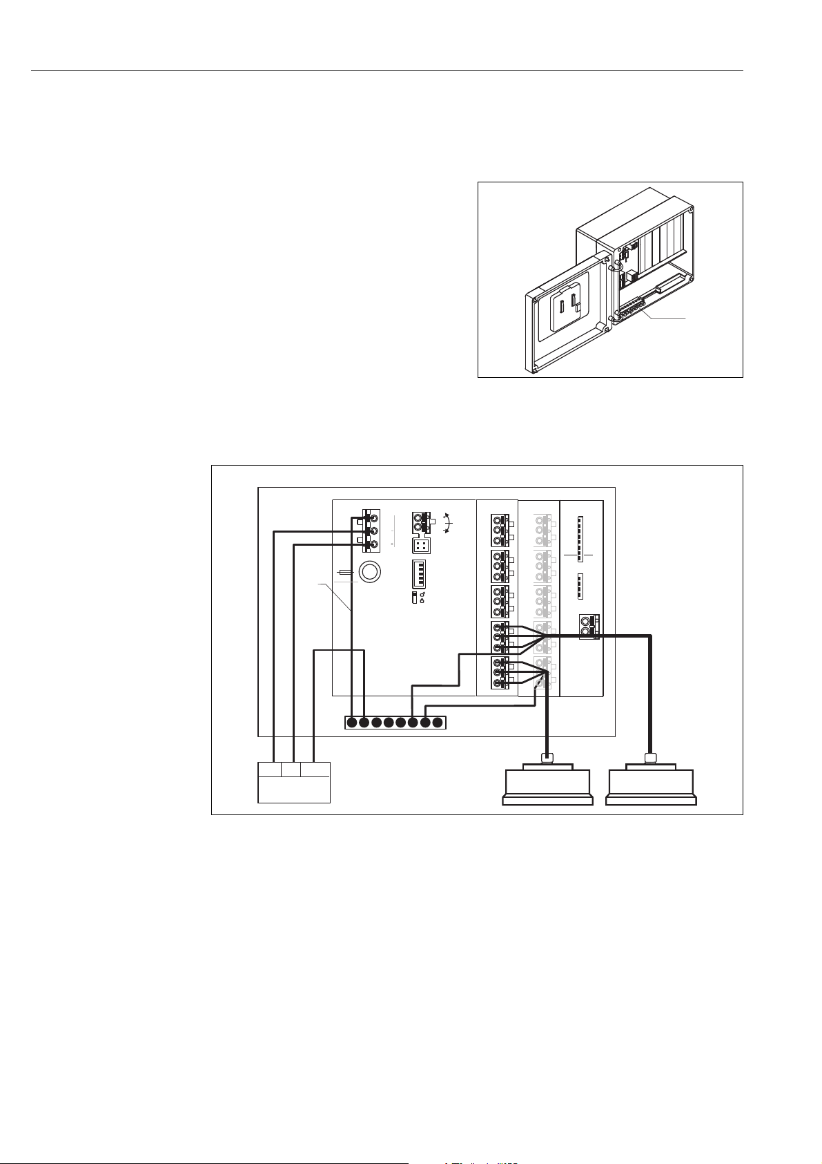
4.8 Potential equalization
4.8.1 Potential equalization in the field housing
Warning!
#
The grounding line of the sensors FDU91F/93/
95/96 and FDU83/84/85/86 must be
connected to the local potential equalization
system after a maximum of 30 m (98 ft),
( ä 20). The metallic terminal block (1) in
the field housing can be used for this.
L00-FMU90xxx-04-00-00 -xx-006
Example
L00-FMU95xxx-04-00-00 -xx-009
1 The wire is already connected on delivery
26 Endress + Hauser
Page 27
Prosonic S FMU95 Wiring
90 … 253 VAC
10.5 … 32 VDC
FMU95
Address
Term.
DP
off
on
off
on
SW
HW
1
2
3
4
5
6
7
8
1
2
3
4
A(N)
66
B(P)
65
Display
POWER
Sync
Fuse
40
39
Service
32
1
11
10
9
1
FDU-Sensor
YE BK RD
14
13
12
2
YE BK RD
17
16
15
3
YE BK RD
20
19
18
4
YE BK RD
23
22
21
5
YE BK RD
26
25
24
6
YE BK RD
29
28
27
7
YE BK RD
32
31
30
8
YE BK RD
35
34
33
9
YE BK RD
38
37
36
10
YE BK RD
FDU-Sensor
GNYE
FDU91F/93/95/96
(FDU83/84/85/86)
GNYE
PE
PE
PE
FDU91F/93/95/96
(FDU83/84/85/86)
L
N
1 2
3
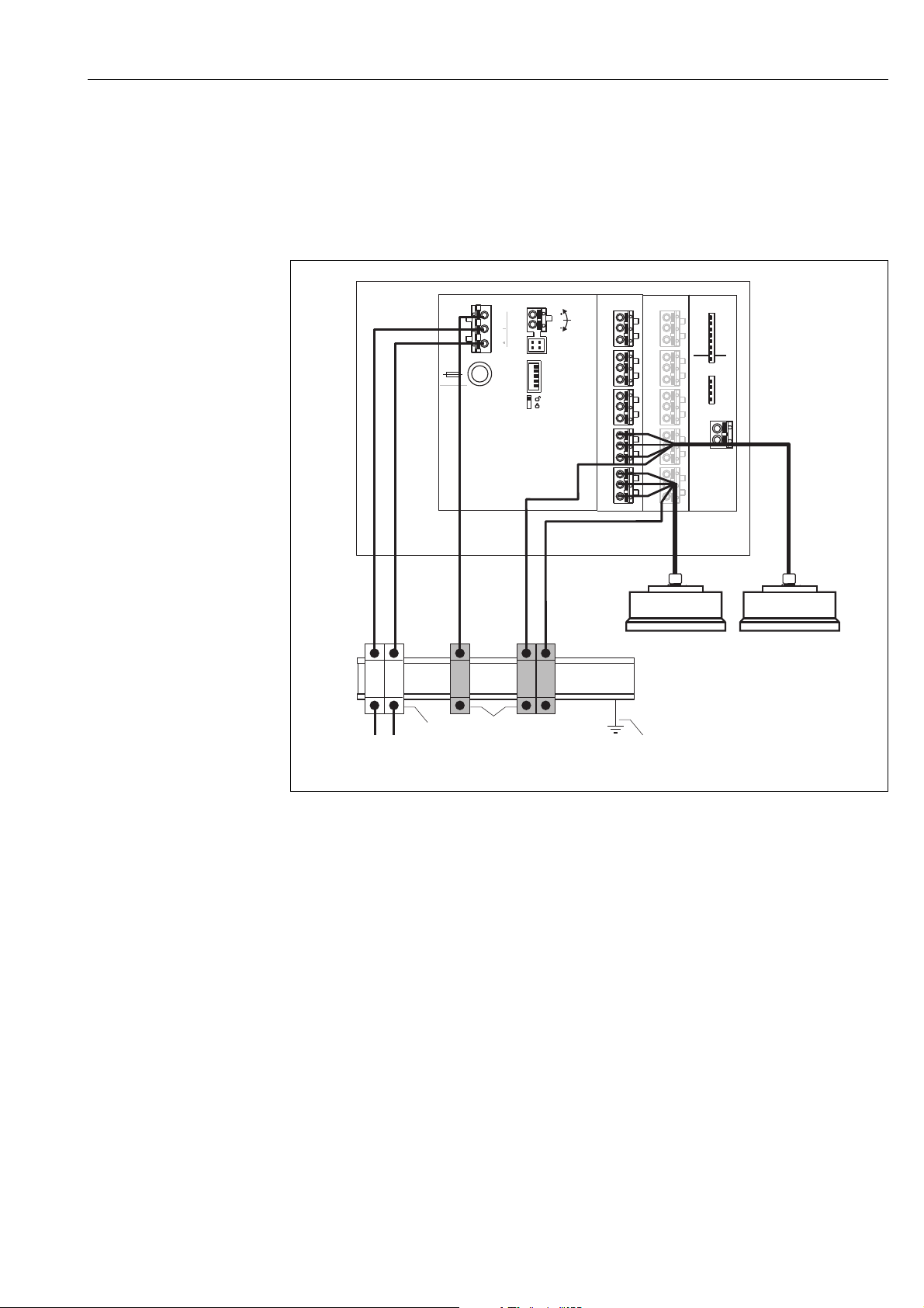
4.8.2 Potential equalization for the DIN-rail hosuing
If the DIN-rail housing is used, the potential equalization must be connected in the cabinet, e.g. at
a metallic DIN rail:
#
Warning!
The grounding line of the sensors FDU91F/93/95/96 and FDU83/84/85/86 must be connected
to the local potential equalization system after a maximum of 30 m (98 ft), ( ä 20).
L00-FMU95xxx-04-00-00-xx-010
1 Terminal (isolated from the DIN rail)
2 Protective earth terminal (with contact to the DIN rail)
3 Protective ground via DIN rail
Caution!
The signal evaluation electronics and its direct connections (display interface, service interface etc.)
are galvanically isolated from the supply voltage and the communication signals. Their electric
potential is identiacal to the potential of the sensor electronics.
Pay attention to the potential difference if the sensors are connected to ground!
Note!
• The longest required distance has to be taken into account when removing the jacket of the sensor
cable (GNYE in the above example).
"
!
• When shortening the sensor cable, comply to the notes ä 23.
Endress + Hauser 27
Page 28

Wiring Prosonic S FMU95
4.9 Post-connection check
After wiring the transmitter, carry out the following checks:
• Is the terminal assignment correct?
• For the field housing: Are the cable glands tight and is the cover of the terminal compartment
securely closed?
• If auxiliary energy is switched on: Does a display appear on the display module (if available) and
does the green LED light up?
28 Endress + Hauser
Page 29
Prosonic S FMU95 Operation
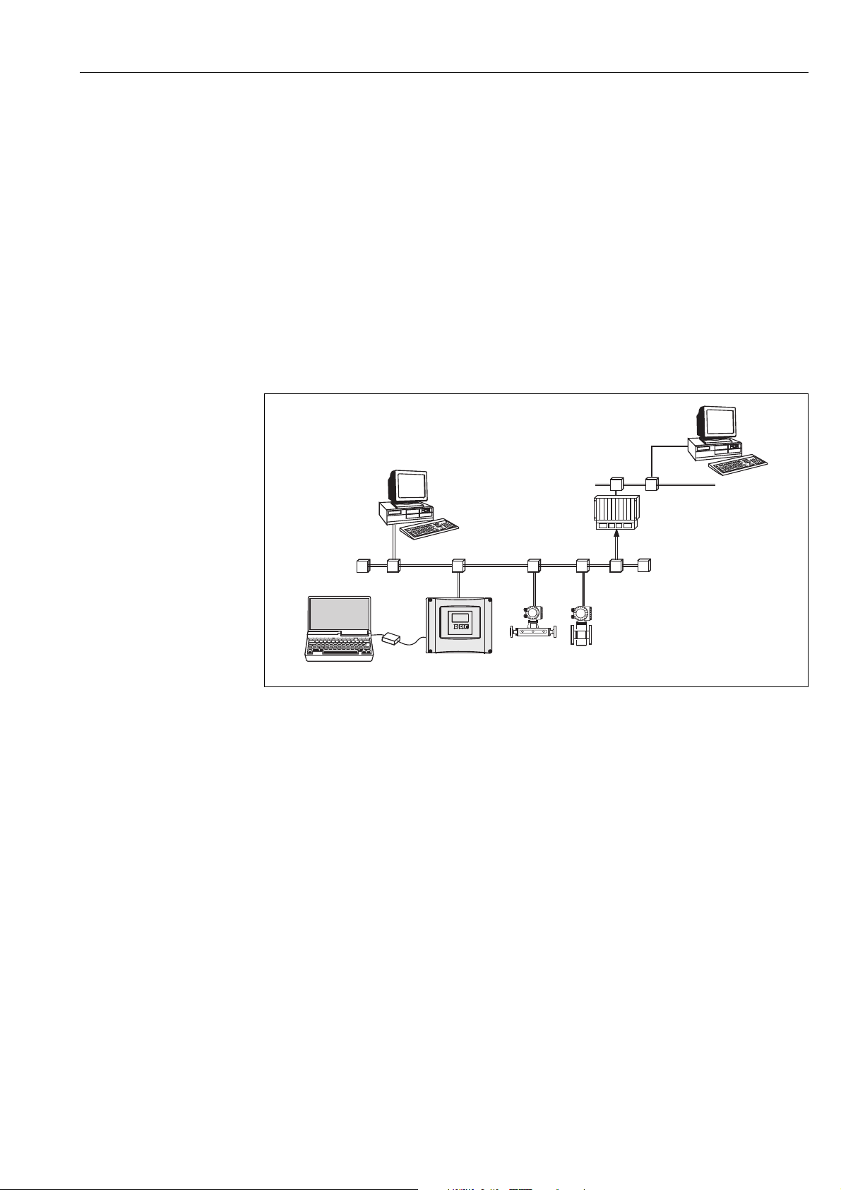
PROFIBUS DP
SPS /
PLC/
API
Ethernet
PDM
...
Prosonic S
PROFIboard
PROFIcard
PROFIusb
Commubox
FXA 291
FieldCare
T
T
FieldCare
5Operation
This chapter gives an overview of the operating options for the intrument. It describes the different
methods of parameter access and states the pre-conditions for each case.
The measning of the individual parameters is not part of this chapter but can be found in:
• Chap. 6: "Commissioning"
• Operating Intructions BA00345F: "Prosonic S FMU95 - Description of Instrument Functions"
This chapter contains the following sections:
• Chap. 5.1 Operating options
• Chap. 5.2 Operation via the display and operating module
• Chap. 5.3 Operation via Endress+Hauser operating tool "FieldCare"
5.1 Operating options
!
!
L00-FMU90xxx-14-00-00-xx-021
5.1.1 On-site operation
• Display and operating module at the Prosonic S
• Endress+Hauser operating tool "FieldCare" with Commubox FXA291
Note!
Commubox FXA291 is an interface adapter from Endress+Hauser.
5.1.2 Remote oepration
Endress+Hauser operating tool "FieldCare" with PROFIcard, PROFIboard or PROFIusb
Note!
PROFIboard, PROFIcard and PROFIusb are interface adapters from Endress+Hauser.
Acyclic data exchange
Remote operation makes use of the acyclic data exchange, which allows device parameters to be
changed independently of the communication between the device and a PLC.
Acyclic data exchange is used
• to transmit device parameters during commissioning and maintenance;
• to display measured values that are not acquired in cyclic traffic.
The Prosonic S supports class 2 masters:
Endress + Hauser 29
Page 30

Operation Prosonic S FMU95
Acyclic communication with a Class 2 master (MS2AC)
In the case of MS2AC, a Class 2 master opens a communication channel via a so-called service
access point (SAP) in order to access the device. Class 2 masters is for example:
• FieldCare
Before data can be exchanged via PROFIBUS, however, the Class 2 master must be made aware of
the parameters contained within the field device. This can be done by:
• a device description (DD)
• a device type manager (DTM)
• a software component within the master, which accesses the parameters via slot and index
addresses.
!
Note!
• The DD or DTM is supplied by the device manufacturer.
• The Prosonic S has two Service Access Points. Therefore, it can be simultaneously accessed by
two Class 2 masters.
• The use of a Class 2 master increases the cycle time of the bus system. This must be taken into
consideration when the control system or PLC is programmed.
Slot-Index tables
The Slot-Index tables for the general acyclic data exchange are summarized in the document
BA00346F on the enclosed CD-ROM (can be downloaded from www.endress.com).
30 Endress + Hauser
Page 31

Prosonic S FMU95 Operation
FMU95
3
1
2
6
5
4
5.2 Operation via the display and operating module
5.2.1 Display and operating elements
L00-FMU95xxx-07-00-00-xx-001
1 Softkey symbol
2Key
3 LED indicating the operating state
4 Display symbols
5 Value of the parameter, including unit
6 Name of the parameter
Display symbols
Symbol Meaning
Operating mode of the instrument
User
User parameters can be edited. Service parameters are locked.
Diagnosis
The service interface is connected.
Service
User and service parameters can be edited.
Locked
All parameters are locked.
Locking state of the currently displayed parameter
Display parameter
The parameter can not be edited in the current operating mode of the instrument.
Editable parameter
The parameter can be edited.
Scroll symbols
Scroll list available
Indicates that the list contains more parameters than can be represented on the display. By pressing
V or W repeatedly, all parameters of the list can be accessed.
Navigation in the envelope curve display
Move left
Move right
Zoom in
Zoom out
Endress + Hauser 31
Page 32

Operation Prosonic S FMU95
LEDs
LED indicating the operating state (pos. 3 in the figure)
green normal measuring mode; no error detected
Warning:
red (flashing)
red
off supply voltage missing
An error is detected but the measurement continues. Reliability of the measured value is no longer
ensured.
Alarm:
An error is detected. The measurement is interrupted. The measured value assumes the value
specified by the user (parameter "output on alarm").
Keys (softkey operation)
The function of the keys depends on the current position within the operating menu (softkey
functionality). The key functions are indicated by softkey symbols in the bottom line of the display.
Symbol Meaning
Move downwards
Moves the marking bar downwards within a selection list.
Move upwards
Moves the marking bar upwards within a selection list.
Enter
• Opens the marked submenu, the marked parameter set or the marked parameter
• Confirms the edited parameter value
Previous parameter set
Reopens the previous parameter set within the submenu.
Next parameter set
Opens the next parameter set within the submenu.
Confirm selection
Selects the option of a selection list which is currently marked by the bar.
Increase value
Increases the active digit of an alphanumeric parameter.
Decrease value
Decreases the active digit of an alphanumeric parameter
Error list
Opens the list of all errors which are currently detected.
If a warning is present, this symbol flashes.
If an alarm is present, the symbol is displayed continuously.
Change Display
Change to the next page of measured values (only available if more than one pages of measured
values have been defined; see "display" menu)
Info
Opens the Shortcut Menu, which contains the most important information about the current state
of the instrument
Menu
Opens the Main Menu, which contains all parameters of the Prosonic S
32 Endress + Hauser
Page 33

Prosonic S FMU95 Operation
32
1
General key combinations
The following key combinations do not depend on the menu position:
Key combination Meaning
Escape
• While editing a parameter: Exit the editing mode without accepting the changes.
• Within the navigation: Move upwards to the previous layer of the menu.
Increase contrast
Increases the contrast of the display module.
Decrease contrast
Decreases the contrast of the display module.
Locking
Locks the instrument against parameter changes.
The instrument can only be unlocked again by the keys.
5.2.2 The operating menu
Structure of the menu
The parameters of the Prosonic S are organized in an operating menu (consisting of a main menu
and several submenus). Parameters which are related to each other are comprised in a common
parameter set. To simplify the navigation within the menu, a five-digit position code is displayed
with each parameter set.
LVL 1 appl.para L1004
tank shape :dome ceiling
medium property:liquid
process cond:standard liq.
Identification of the parameter sets:
1Submenu
2 Number of the associated input or output
3 Number of the parameter set within the submenus
•The first digit (1) specifies the submenu
– L: "level"
– A: "safety settings"
– O: "output/calculations"
– D: "device properties", "calibr. display" and "sensor management"
– I: "system information"
– S: "service" (only available if the service password has been entered)
1)
:
Diagrams of the submenus can be found in the chapter "Operating menu".
1) Depending on the instrument version, the installation environment and the selected operating mode, some of the submenus may not be present.
Endress + Hauser 33
Page 34

Operation Prosonic S FMU95
•The second digit (2) is used if the parameter set occurs several times within the Prosonic S (e.g.
for different inputs or outputs).
Example:
– L1002: level 1
– L2002: level 2
– ...
– L9002: level 9
– LA002: level 10
If the parameter set occurs only once wihtin the Prosonic S, "X" is indicated at this position.
•The last three digits (3) specify the individual parameter sets within the submenu.
Parameter types
Display parameters
Parameters for which the symbol is displayed in the left bottom corner of the display
module, are either locked or display-only parameters.
Editable parameters
L00-FMU90xxx-07-00-00-e n-041
L00-FMU90xxx-07-00-00-e n-044
Parameters, for which the symbol is displayed in the left bottom corner of the display
module, can be entered for editing by pressing
.
The editing procedure depends on the type of
parameter:
• when entering a selection parameter, the
associated selection list appears (see below:
"Editing a parameter with selection list").
• when entering a numerical or alphanume-
rical parameter, the text and number editor
appears (see below: "Entering numbers and
characters").
34 Endress + Hauser
Page 35

Prosonic S FMU95 Operation
CX001
main menu
level
flow
safety settings
ralay/controls
…
LX001
level
L1002
level 1
Return
input: sensor 1
sensor sel.: autom.
detected: FDU91
tank shape: dome
medium proper: liq.
proc. cond.: stand.
5.00 m
level (LVL) 1
...
...
basic setup
extended calibr.
simulation
L1004
LVL1 appl. para
tank shape: dome
medium proper: liq.
proc. cond.: stand.
L100A
tank shape
dome ceiling
horizontal cyl.
bypass
stilling well
L1004
LVL1 appl. para
L100A
tank shape
dome ceiling
horizontal cyl.
bypass
stilling well
L1004
LVL1 appl. para
tank shape: bypass
medium proper: liq.
proc. cond.: stand.
L1004
LVL1 appl. para
tank shape: bypass
medium proper: liq.
proc. cond.:stand.
L1005
LVL1 empty cal.
level 1
67.60 %
=
L1003
LVL1 sensor sel.
Menu
Main Menu
Submenus
Parameter Set
(here: with 3 parameters)
Editing a
parameter with
selection list
Navigation within the menu (Example)
Endress + Hauser 35
L00-FMU90xxx-19-00-00-en-050
Page 36

Operation Prosonic S FMU95
shortcut menu main menu
actual error
level
Warning 01802
safety settings
Alarm 01502
tag marking
envelope curve
language
device information
password/reset
...
...
...
...
FMU95
Entering the menu
The navigation always starts from the main screen (measured value display
2)
). From there, the
following menus can be opened by the keys:
• shortcut menu
The shortcut menu is accessed via the "Info" key. It allows quick access to device information:
–tag marking
– envelope curve: used to check the signal quality
– language: sets the display language
– device information: serial number, versions of software and hardware
– password/reset: used to enter the password or reset code
All parameters of the shortcut menu are contained in the main menu as well.
• main menu
The main menu is accessed via the "Menu" key. It contains all parameters of the Prosonic S. It
is divided into submenus. Some of the submenus consist of further submenus. Which submenus
are actually present, depends on the instrument version and the installation environment.
An overview of all submenus and parameters is given in the chapter "Operating menu".
• actual error
If the self-monitoring of the Prosonic S detects an error, the softkey symbol appears
above the middle key.
If the softkey symbol flashes, only "warnings" are present.
If the softkey symbol is displayed permanently, at least one "alarm" is present.
After pressing the key, a list of all currently present errors appears.
L00-FMU95xxx-19-00-00-en-002
2) Note: Depending on the configuration, the appearance of the measured value display may be differemt from the example in the figure.
36 Endress + Hauser
Page 37

Prosonic S FMU95 Operation
1.
2.
3.
main menu
“device properties”
submenu
“distance unit”
parameter set
Selecting a submenu
1. In the main menu press W or V until the
required submenu is marked by the bar.
Note!
!
The symbols indicate that the
selection list contains more items than can be
displayed on the module. Press W or V several
times, to mark one of the hidden items.
2. Press , in order to enter the marked
submenu.
3. If the submenu contains further submenus,
continue until you reach the level of the
parameter sets. This level is reached if the
softkey symbols U and T appear.
L00-FMU95xxx-19-00-00-en-005
!
Note!
If necessary, you can return to the previous level of the menu by pressing .
Endress + Hauser 37
Page 38

Operation Prosonic S FMU95
1.
1.
3.
2.
4.
Selecting a parameter
By pressing U or T you can switch between the parameter sets of the current submenu. For each
parameter set the values of all its parameters are displayed. In order to change one of the values,
proceed as follows:
1. Press U or T, until you have reached the
required parameter set.
2. Press , in order to enter the parameter set.
3. Select the required parameter by pressing
W or V.
(This step is not required if the set contains
only one parameter.)
4. Press , in order to enter the editing mode
of the parameter.
The editing method depends on the type of
parameter (selection list, numeric or
alphanumeric parameter). For details refer
to the following sections.
!
Note!
If necessary, you can exit the parameter and parameter set by pressing .
L00-FMU90xxx-19-00-00-e n-040
38 Endress + Hauser
Page 39

Prosonic S FMU95 Operation
1.
2.
3.
Editing a parameter with selection list
1. Press W or V, until the required option is
marked by the bar (in the example: "turb.
surface").
Note!
!
The symbols indicate that the
selection list contains more items than can
be displayed on the module. Press W or V
several times, to mark one of the hidden
items.
2. Press ✓, in order to select the marked
option. It is then stored in the instrument.
3. Press the left and middle keys
simultaneously in order to quit the
parameter.
The software key symbols U and T
reappear and you can switch to the next
parameter set.
!
Note!
By pressing before ✓ you can quit the parameter without accepting your changes.
L00-FMU90xxx-19-00-00-en-041
Endress + Hauser 39
Page 40

Operation Prosonic S FMU95
1.
2.
3.
4.
5.
6.
Entering numbers and characters
When you select a numeric parameter ("empty
calibration", "full calibration" etc.) or an alphanumeric parameter ("device marking" etc.), the
editor for numbers and text strings appears.
Enter the desired value in the following way:
1. The cursor is at the first digit. Press S or O
until this digit has the required value.
jump to the next digit.
3. Repeat the procedure for all relevant digits.
2. Press in order to confirm the value and to
4. If all relevant digits have been entered:
Press S or O, until appears at the cursor.
5. Press to store the complete value in the
device.
6. Press the left and middle keys simultaneously in order to quit the parameter.
L00-FMU90xxx-19-00-00-yy-042
40 Endress + Hauser
Page 41

Prosonic S FMU95 Operation
Special editing functions
Within the editor for alphanumeric characters, pressing S or O does not only lead to numbers and
characters but also to the following symbols for special editing functions. They simplify the editing
procedure.
L00-FMU90xxx-19-00-00-yy-043
Enter: The number left of the cursor is transferred to the instrument.
L00-FMU90xxx-19-00-00-yy-044
Escape: The editor is closed. The parameter maintains its former value. The same behavior can be achieved by pressing
the left and the middle key simultaneously ( ).
L00-FMU90xxx-19-00-00-yy-045
Next digit: The cursor moves on to the next digit.
L00-FMU90xxx-19-00-00-yy-046
Previous digit: The cursor moves back to the previous digit.
Endress + Hauser 41
Page 42

Operation Prosonic S FMU95
FMU95
L00-FMU90xxx-19-00-00-yy-047
Delete: The current digit and all digits to its right are deleted.
Return to the measured value display
By pressing the left and middle keys
simultaneously you can return
• from a parameter to the parameter set
• from the parameter set to the submenu
• from the submenu to the main menu
• from the main menu to the measured value
display
L00-FMU95xxx-19-00-00-e n-003
42 Endress + Hauser
Page 43

Prosonic S FMU95 Operation
1
2
5.3 Operation via Endress+Hauser operating tool
"FieldCare"
L00-FMU90xxx-19-00-00-en-087
Operation via the FieldCare is similar to the operation via the display module.
• The operating menu can be found in the navigation bar (1).
• Input fields for the parameters can be found in the parameter editor (2).
• When you click on a parameter name, the help pages appear. They contain a detailed description
of the respective parameter.
Endress + Hauser 43
Page 44

Commissioning Prosonic S FMU95
6 Commissioning
#
Warning!
For the version with field housing: The instrument may only be operated if the field housing is
closed.
This chapter describes the steps of the commissioning procedure:
• 6.1 Preparatory steps
– 6.1.1 Setting the device address
– 6.1.2 Bus termination
– 6.1.3 Loading the devic database files (GSD files)
– 6.1.4 Unlock configuration
– 6.1.5 Reset to the default configuration
• 6.2 Configuration of the measurement
– 6.2.1 First setup
– 6.2.2 Preparing the basic setup
– 6.2.3 Basic setup
– 6.2.4 Checking the measuring signal (envelope curve display)
– 6.2.5 Deactivation of unused sensor inputs
• 6.3 Parametrization of the Anaolg Input Blocks
• 6.4 Parametrization of the cyclic data telegram
• 6.5 Parametrization of the on-site display
6.1 Preparatory steps
6.1.1 Setting the device address
Selecting the device address
• Every PROFIBUS device must be given an address. If the address is not set correctly, the device
will not be recognised by the process control system.
• A device address may appear only once within a particular PROFIBUS network.
• Valid device addresses are in the range between 1 and 126. All devices are delivered from the
factory with the address 126, which is set by software.
• The default address can be used to check the function of the device and connect it to an operating
PROFIBUS system. Afterwards the address must be changed to allow other devices to be
connected to the network.
Software addressing
Software addressing comes into operation, when DIP-switch 8 on the PROFIBUS DP terminal area
is in the position "ON".
In this case, the address can be set by an operating tool ("FieldCare").
The address is displayed in the function "Output-calculations/PROFIBUS DP/instrument address".
44 Endress + Hauser
Page 45

Prosonic S FMU95 Commissioning
Address
Term.
DP
off
on
off
on
SW
HW
1
2
3
4
5
6
7
8
1
2
3
4
Address
off
on
SW
HW
1
2
3
4
5
6
7
8
8 + 2 = 10
A(N)
66
B(P)
65
Address
Term.
DP
off
on
off
on
SW
HW
1
2
3
4
5
6
7
8
1
2
3
4
A(N)
66
B(P)
65
Term.
off
on
1
2
3
4
Term.
off
on
1
2
3
4
AB
Hardware addressing
L00-FMU90xxx-04-00-00-xx-016
Hardware addressing comes into operation when DIP switch 8 is in the position "HW (OFF)". In this
case the address is determinded by the position of DIP-switches 1 to 7 according to the following
table:
Switch No. 1234567
Value in position "OFF"0000000
Value in Position "ON"1248163264
The new address becomes valid 10 seconds after switching.
6.1.2 Bus termination
The termination resistor must be activated for the last instrument on the bus. This is done by setting
all four termination switches into the "on" position.
L00-FMU90xxx-04-00-00-xx-018
A: termination off (factory setting); B: termination on
Endress + Hauser 45
Page 46

Commissioning Prosonic S FMU95
Prosonic_S/DP/Profile3/Revision1.0/
BMP/
Eh154E_d.bmp
Eh154E_n.bmp
Eh154E_s.bmp
DIB/
Eh154E_d.dib
Eh154E_n.dib
Eh154E_s.dib
GSD/
Extended/Eh3x154E.gsd
Info/
Liesmich.pdf
Readme.pdf
6.1.3 Loading the device database and type files (GSD)
Meaning of the GSD files
A device database file (GSD) contains a description of the properties of the PROFIBUS device, e.g.
the supported transmission rates and the type and format of the digital information output to the
PLC. Additional bitmap files are required in order to represent the device by an icon in the network
design software. The device database and bitmap files are needed for the commissioning of a
PROFIBUS DP network.
Name of the GSD file
Every device is allocated an identity code by the PROFIBUS User Organisation (PNO). This appears
in the device data base file name (.gsd).
The FMU95 has the ID number 154E(hex) = 5454 (dec).
Therefore, the name of the GSD file is: EH3x154E.gsd
Sources of supply
• www.endress.com
click on "Download" and enter "GSD" into the "Text search" field. The "Software" link opens a list
containing the links to all available GSD files.
• CD-ROM with GSD files for all Endress+Hauser devices. Order-Code: 50097200
• GSD library of the PROFIBUS User Organisation (PNO):http: //www.PROFIBUS.com
Directory structure
The files are organized in the following structure:
L00-FMU95xxx-02-00-00 -xx-001
Universal Database File
As an alternative to the device specific GSD file, the PNO provides an universal database file without
instrument specific features.
When the universal database file is used, the option "profile" must be selected in the "Output-
46 Endress + Hauser
calculation/PrOFIBUS DP/ident number" parameter.
Usage of the GSD files
The GSD files must be loaded to a specific subdirectory of the PROFIBUS DP configuration software.
Depending on the software, the GSD files must be copied into the directory or an import
functionality of the software may be used.
Detailed information about the appropriate file location can be obtained from the manual of the
respective configuration software.
Page 47

Prosonic S FMU95 Commissioning
6.1.4 Unlock configuration
If appears on the display, the instrument is locked against parameter changes. Before
commissioning the instrument must be unlocked.
For the Prosonic S there are three types of locking:
• Software locking
• Locking by key combination
• Hardware locking
Indication of the locking state
The current locking state of the instrument is displayed in the parameter "device properties/
password-reset/status". The following states may occur:
• unlocked
All parameters (except of service parameters) can be changed.
• code locked
The instrument has been locked via the operating menu. It can be unlocked by entering the
unlocking code into the "code" parameter.
• key locked
The key has been locked by a key combination. It can only be unlocked by pressing all three keys
simultaneously.
• switch locked
The instrument has been locked by the switch in the terminal compartment. It can only be
unlocked by this switch.
Software locking
Locking
Go to the parameter "device properties/passoword-reset/code" and enter a value 2457. The
instrument is locked against parameter changes.
The symbol appears on the display.
Unlocking
If you try to change a parameter, the "password-reset" parameter set appears. Select the "code"
parameter and enter "2457". Parameters can be changed again.
Locking by key combination
Locking
Press all three keys simultaneously. The instrument is locked against parameter changes.
The symbol appears on the display.
Unlocking
If you try to change a parameter, the "password/reset" parameter set appears. "key locked" is
displayed in the "status" parameter. Press all three keys simultaneously. Parameters can be changed
again.
Endress + Hauser 47
Page 48

Commissioning Prosonic S FMU95
Display
POWER
Sync
Fuse
40
39
Service
3
2
1
A
B
Hardware locking
The instrument can be locked against parameter changes by the locking switch in the terminal
compartment of the Prosonic S.
"
!
L00-FMU90xxx-19-00-00-yy-105
Switch position A: unlocked; parameters can be changed
Switch position B: locked; parameters can not be changed.
If the switch is in position B, appears on the display and parameters can not be changed. The
instrument can only be unlocked by the switch.
6.1.5 Reset to the default configuration
Caution!
A reset may lead to impairment of the measurement. As a rule, a basic calibration is required after
a reset.
Application of the Reset
It is advisable to reset the customer parameters if you want to use a device with an unknown history.
Effects of the Reset
• All parameters are reset to their default values.
• The linearisation type is switched to "none". If a linearisation table is present, it is not deleted. If
required, it can be reactivated at a later point of time.
• An interference echo curve is set "inactive". However, the curve is not deleted and can be
reactivated at a later point of time.
Note!
In the menu diagrams ( ä 96, "Operating menu") the default values of the parameters are printed
in bold.
Performing a Reset
In order to perform a reset, enter "33333" into the parameter "device properties/password-reset/
reset".
48 Endress + Hauser
Page 49

Prosonic S FMU95 Commissioning
5-point linearity protocol
!
!
Note!
The specified measuring accuracy is a typical value ä 94, "Performance characteristics".
With the production of the 5-point linearity protocol the measuring system (FDU9x sensor and
FMU9x transmitter electronic) is adjusted exactly to one another and the measuring accuracy is
optimized for the specified range.
To realize this, the parameter "zero distance" is fine adjusted. After a reset the value for the zero
distance has to be re-parameterized in the service menu according to the data on the associated 5point linearity protocol for the FDU9x sensor. Please contact the Endress+Hauser service.
6.2 Configuration of the measurement
6.2.1 First setup
Note!
This chapter describes the commissioning of the Prosonic S via the display and operating module.
Commissioning via FieldCare is similar. For further instructions refer the FieldCare Online Help.
After switching on the power supply for the first time, the instrument asks for a number of operating
parameters:
1. Select the display language.
!
a. Press or to move the marking bar to the
desired language.
b. Press to confirm your selection.
L00-FMU90xxx-07-00-00-yy-027
2. Select the unit for distance measurements.
L00-FMU90xxx-07-00-00-en-028
3. Select the temperature unit.
L00-FMU90xxx-07-00-00-en-029
Note!
By pressing you can return to the previous parameter (e.g. in order to correct the value).
All these parameters can also be changed at a later point of time in the "device properties/operating
parameters" and "device properties/language" parameter sets.
Endress + Hauser 49
Page 50

Commissioning Prosonic S FMU95
6.2.2 Preparing the basic setup
1. After the first setup the main screen appears.
However, the displayed value does not correspond
to the real level before you have performed the
basic setup. To do so, enter the main menu by
pressing "Menu" (right key).
Note!
!
In the "calibr. display" menu you can adjust the
display to your requirements (displayed values,
display format). The figure shows an example for a
2-channel instrument.
2. Select the "level" submenu.
– Select by and
– Confirm by
3. In the following submenu select the level channel
you are going to calibrate.
L00-FMU90xxx-07-00-00-en-049
L00-FMU95xxx-07-00-00-en-003
4. In the following submenu select "basic setup".
This submenu contains all parameters needed for
the basic setup.
L00-FMU95xxx-07-00-00-en-004
L00-FMU90xxx-07-00-00-en-035
50 Endress + Hauser
Page 51

Prosonic S FMU95 Commissioning
6.2.3 Basic setup
Overview
The following table gives an overview of the basic setup for level measurements. Detailed
information on the parameters can be found in the sections 6.3.2. to 6.3.11.
Step Parameter Set Parameter Remarks page
Configuring the sensor
1 LVL N sensor selection
(N = 1 - 10)
2 LVL N application parameter
(N = 1 - 10)
3 LVL N empty calibration
(N = 1 - N)
4 LVL N full calibration
(N = 1 - 10)
5LVL N unit
(N = 1 - 10)
Linearisation (if no linearisation is required: continue by step 7: "distance correction")
6 LVL N linearisation
(N = 1 - 10)
input Allocate a sensor to the channel. 53
sensor selection Specify the type of sensor ("automatic" for FDU9x)
detected only available for "sensor selection" = "automatic";
indicates the detected type of sensor.
tank shape Select the appropriate values for your application 54
medium property
process conditions
empty E Specify the distance between the sensor membrane and the minimum level
full F Specify the distance between the minimum (0%) and maximum (100%)
blocking distance (BD) Display parameter; the maximum value for the full calibration is:
unit level Select the unit for the level measurement. 58
level N (N = 1 - 10) Displays the currently measured level.
sensor Displays the currently measured distance between the sensor membrane and
type Select type of linearisation 59
mode Specify, to which value the measurement refers:
customer unit Specify the unit for the linearized value;
max. scale Specify the maximum contents of the vessel (in customer units);
diameter Specify the diameter of the tank;
intermediate height Specify the intermediate height of the tank or silo;
edit Used to enter, change or delete a linearisation table;
status table Enables or disables the linearisation table;
(0%).
level.
F
= E - BD
max
the product level.
"level" or "ullage"
(not available for "type" = "none")
(not available for "type" = "none")
(only available for "type" = "horizontal cylinder" or "sphere")
(only available for "type" = "pyramid bottom", "conical bottom" oder "angled
bottom")
(only available for "type" = "table")
(only available for "type" = "table")
56
57
Endress + Hauser 51
Page 52

Commissioning Prosonic S FMU95
Step Parameter Set Parameter Remarks page
Interference echo suppression
7 lvl N check value
(N = 1 - 10)
8LVL N dist. map.
(N = 1 - 10)
9LVL N state
(N = 1 - 10)
act. distance N
(N = 1 - 10)
check distance Compare the indicated distance with the real value:
act. distance N
(N = 1 - 10)
range of mapping Determines the range over which the mapping is recorded;
start mapping Select:
level N
(N = 1 - 10)
act. distance Indicates the currently measured distance between the sensor membrane
status Used to enable, disable or delete a mapping
Indicates the currently measured distance between the sensor membrane
and the product surface.
• "distance = ok" "distance mapping" (see below)
• "distance too small" "distance mapping" (see below)
• "distance too big" Basic setup completed
• "distance unknown" Basic setup completed
• "manual" "distance mapping" (see below)
Indicates the currently measured distance between the sensor membrane
and the product surface.
confirm the predefined value or enter your own value.
• no: the mapping is not recorded
• yes: the mapping is recorded; after completion the "LVL N state" function
appears (see below)
Indicates the currently measured level. 67
and the product surface. Check the value:
• Value correct: Basic setup completed.
Return to the measured value display by pressing several times
• Value not incorrect: go back to step 7 ("distance correction")
65
66
!
Hinweis!
In order to optimeze the cycle time of the measured value update, it is recommended to deactivate
unused measuring channels in the "sensor management" menu ä 67.
52 Endress + Hauser
Page 53

Prosonic S FMU95 Commissioning
"LVL N sensor selection" (N = 1 - 10)
LVL1 sensor sel. L1003
input:
!
"
sensor selection:
detected:
"input"
Use this parameter to assign a sensor to the channel.
Selection:
• no sensor
•sensor 1
• ...
•sensor 10
"sensor selection"
Use this parameter to specify the type of the connected ultrasonic sensor.
Note!
• For the sensors FDU9x the option "automatic" is recommended (default setting). With this setting
the Prosonic S recognizes the type of sensor automatically.
• For the sensors FDU8x the type has to be assigned explicitly. The automatic sensor recognition
does not work for these sensors.
Caution!
After exchanging a sensor, observe the following:
The automatic sensor recognition is also active after a sensor has been exchanged
recognizes the type of the new sensor automatically and changes the "detected" parameter if
required. The measurement continues without a break.
Nevertheless, in order to ensure perfect measurement, the following checks are required:
•Check the "empty calibration" and "full calibration" parameters. Adjust these values if
required. Take into account the blocking distance of the new sensor.
•Go to the "LVL N check value" parameter set (last set of the basic setup) and check the
displayed distance. If required, perform a new interference echo suppression.
3)
. The Prosonic S
"detected" (only available for "sensor selection" = "automatic")
Indicates the type of the automatically detected sensor.
3) if the new sensor is of the type FDU9x
Endress + Hauser 53
Page 54

Commissioning Prosonic S FMU95
A
BC
D
E
F
"LVL N application parameters" (N = 1 - 10)
LVL1 appl. para. L1004
tank shape:
medium property:
process cond.:
"tank shape"
Use this parameter to specify the tank shape of your application.
Selection:
L00-FMU90xxx-14-00-00 -xx-002
A Dome ceiling
B Horizontal cyl.
C Bypass, stilling well/ultrasonic guide pipe
D No ceiling, e.g. dumps, open levels, chanels, weirs
E Sphere
F Flat ceiling
"medium property"
Use this parameter to specify the type of medium.
Selection:
!
• liquid
• paste like
•solid < 4 mm
•solid > 4 mm
• unknown
Note!
If the medium does not fit into one of the groups, select "unknown".
54 Endress + Hauser
Page 55

Prosonic S FMU95 Commissioning
"process conditions"
Use this parameter to specify the process conditions of your application. The filters of the signal
evaluation are automatically adjusted to the selected conditions.
"process conditions" for the following situations Example filter settings
standard liquid for all fluid applications which do
not fit in any of the following
groups
calm surface Storage tanks with immersion
tube or bottom filling
The filters and output damping are set
to average values.
The averaging filters and output
damping are set to large values.
-> stable measured value
-> accurate measurement
-> slow reaction time
turbulent surface Storage/accumulation tanks with
uneven surface due to free filling,
mixing nozzles or small bottom
stirrers
additional agitator Moving surfaces (possibly with
vortex formation) due to agitators
fast change Rapid level change, particularly in
small tanks
standard solid For all bulk solid applications
which do not fit in any of the
following groups.
Special filters for stabilizing the input
signal are activated.
-> stable measured value
-> medium reaction time
Special filters for stabilizing the input
signal are set to large values.
-> stable measured value
-> medium reaction time
The averaging filters are set to small
values.
-> rapid reaction time
-> possibly unstable measured value
The filter and output damping are set
to average values.
solid dusty Dusty bulk solids The averaging filters are set to detect
even relatively weak signals.
conveyor belt Bulk solids with rapid level change The averaging filters are set to small
test: no filter For service and diagnosis only All filters are switched off
values.
-> rapid reaction time
-> possibly unstable measured value
Endress + Hauser 55
Page 56

Commissioning Prosonic S FMU95
0/4 mA
0%
E
"LVL N empty calibration" (N = 1 - 10)
LVL1 empty cal. L1005
empty E: 0,00 m
"empty E"
Use this parameter to specify the empty distance E, i.e. the
distance between the sensor membrane (reference point of the
measurement) and the minimum level (zero point).
– Default: max. measuring range of the respective sensor
– Range of values: depending on sensor type
Caution!
"
The zero point should not be deeper than the point at which the
L00-FMU90xxx-19-00-00-yy-007
ultrasonic wave impinges on the tank bottom
56 Endress + Hauser
Page 57

Prosonic S FMU95 Commissioning
20 mA
100%
0/4 mA
0%
BD
F
E
"LVL N full calibration" (N = 1 - 10)
LVL1 full calib. L1006
full F: 0,00 m
block.dist. BD:
"full F"
Use this parameter to specify the span F, i.e. the distance from the
minimum level to the maximum level.
– Default setting: depending on sensor type
– Range of values: depending on sensor type
– blocking distance BD: depending on sensor type (see table)
Caution!
"
The maximum level may not project into the blocking distance:
L00-FMU90xxx-19-00-00 -yy-008
F
max
= E - BD
"blocking distance"
Indicates the blocking distance of the respective sensor. The blocking distance is measured from the
sensor membrane (reference point of the measurement).
Type of sensor Blocking distance (BD) Maximum measuring distance
FDU90 0.07 (0.2) 3.0 (9.8) (for liquids)
FDU91/FDU91F 0.3 (1.0) 10 (33) (for liquids)
FDU92 0.4 (1.3) 20 (66) (for liquids)
FDU93 0.6 (2.0) 25 (82) (for liquids)
FDU95 - *1*** (low temperature version) 0.7 (2.3) 45 (148) (for solids)
FDU95 - *2*** (high temperature version) 0.9 (3.0) 45 (148) (for solids)
FDU96 1.6 (5.2) 70 (230) (for solids)
FDU80/FDU80F 0.3 (1.0) 5 (16) (for liquids)
FDU81/81F 0.5 (1.6) 10 (33) (for liquids)
FDU82 0.8 (2.6) 20 (66) (for liquids)
FDU83 1.0 (3.3) 25 (82) (for liquids)
FDU84 0.8 (2.6) 25 (82) (for solids)
FDU85 0.8 (2.6) 45 (148) (for solids)
FDU86 1.6 (5.2) 70 (230) (for solids)
m (ft)
1)
1) valid for optimum process conditions
Endress + Hauser 57
Page 58

Commissioning Prosonic S FMU95
0/4 mA
0%
F
D
"LVL N unit" (N = 1 to 10)
LVL 1 unit level L1007
unit level:
level 1:
sensor:
"unit level"
Use this parameter to select the distance unit.
If no linearization is performed, the level is displayed in this unit.
Selection:
•m
•ft
•inch
•mm
• % (Default)
"level N" (N = 1 - 10)
Displays the currently measured level F (from the zero point to the product surface) in the selected
unit.
L00-FMU90xxx-19-00-00-yy-021
"sensor"
Displays the currently measured distance D (from the sensor membrane (reference point of the
measurement) to the product surface) in the distance unit. If the display value does not match the
real distance, an interference echo suppression must be performed prior to linearization.
L00-FMU90xxx-19-00-00-yy-022
!
58 Endress + Hauser
Note!
The distance unit is defined during the first setup of the instrument. If required, it can be changed
in the "device properties/operating params" menu.
Page 59

Prosonic S FMU95 Commissioning
100%
20
mA
0%
0/4
mA
(a)
kg
m
ft
3
3
"LVL N linearisation" (N = 1 - 10)
LVL 1 linearisat. L1008
type:
mode:
Note!
!
Number and type of the parameters in this set depend on the
selected linearization type.
Only the parameters "type" and "mode" are always present.
The "linearization" is used to convert the level into other quantities. Especially, it can calculate the
volume or mass within a vessel of arbitrary shape. The Prosonic S provides different linearization
modes for the most common types of vessels. Additionally, a linearization table for arbitrarily shaped
vessels can be entered.
"type"
Use this parameter to select the type of linearisation.
Selection:
• none
In this linearization type the measured level is not converted but displayed in the selected level
unit (see above, "unit level").
• linear
In this linearization type the displayed value is proportional to the measured level.
The following additional parameter have to be specified:
– the unit for the linearized value, e.g. kg, m
3
, ft3, ... ("customer unit")
– the maximum capacity (a) of the vessel, measured in the customer unit ("maximum scale").
Endress + Hauser 59
Page 60

Commissioning Prosonic S FMU95
100%
20
mA
0%
0/4
mA
(D)Ø
(a)
kg
m
ft
3
3
100%
20
mA
0%
0/4
mA
= kg,m3,ft3, ...
H
(a)
A
B
• horizontal cylinder
4)
• sphere
In these linearization types the measured level is convertet to the volume in a horizontal cylinder
or a spherical tank.
The following additional parameters have to be specified:
– the unit of the linearized value, e.g. kg, m
3
, ft3, ... ("customer unit")
– the diameter (D) of the tank ("diameter")
– the maximum capacity (a) of the tank, measured in the customer unit ("maximum scale").
• angled bottom (A)
• pyramid bottom (B)
• conical bottom (B)
In these linearisation modes the measured level is converted to the volume in the respective type
of vessel.
The following additional parameters have to be specified:
– the unit for the linearized value, e.g. kg, m
3
, ft3, ... ("customer unit")
– the intermediate height H according to the diagram ("intermediate height")
– the maximum capacity (a) of the tank, measured in the customer unit ("maximum scale").
4) This option is only valid for horizontal cylinders without bumped ends. For tanks with bumped ends, a linearization table can be calculated and stored in the
instrument with the FieldCare operating program.
60 Endress + Hauser
Page 61

Prosonic S FMU95 Commissioning
100%
20
mA
0%
0/4
mA
kg
m
ft
3
3
• table
In this linearization mode the measured value is calculated from a linearization table. The table
may consist of up to 32 pairs of values (level - volume). The table must be monotonically
increasing or decreasing.
The following additional parameters have to be specified:
– the unit of the linearized value, e.g. kg, m
3
, ft3, ... ("customer unit")
– the linearization table ("edit")
Endress + Hauser 61
Page 62

Commissioning Prosonic S FMU95
100%
20
mA
0%
0/4
mA
A
B
"customer unit"
Use this parameter to select the desired unit for the linearized values (e.g. kg, m
3
, ft3, ...). This unit
is only indicated on the display. It does not cause a conversion of the measured value.
!
Note!
After selecting the option "customer specific", the parameter "customized text" appears. An arbitrary
string (consisting of up to 5 alphanumeric characters) can be entered into this parameter.
"maximum scale"
Use this parameter to specify the maximum content of the vessel in the customer unit.
"diameter"
Use this parameter to specify the diamter of the horizontal cylinder or the spherical tank
respecitvely.
"intermediate height"
Use this parameter to specify the intermediate height of the vessel.
"mode"
L00-FMU90xxx-19-00-00-yy-015
Use this parameter to specify if the measurement
refers to the "level" (A) or to the "ullage" (B).
62 Endress + Hauser
Page 63

Prosonic S FMU95 Commissioning
No.
Level
Value
1
0,0000
0,0000
2
0,0000
0,0000
3
0,0000
0,0000
…
0,0000
0,0000
: go to next row
: go to previous row
: open marked row
for editing
No.
Level
Value
1
0,0000
0,0000
2
0,0000
0,0000
3
0,0000
0,0000
…
0,0000
0,0000
: navigate within the table
: (for "Level" und "Value”)
open marked number
for editing
: (for "No.")
open row editor
Row function
(before current row)
Query: new position
Return to the previous
step by this
key combination.
- Delete row
- Insert row
- Move row
"edit"
Use this parameter to enter, change or read a linearization table. There are the following options:
• read:
The table editor is opened. The existing table can be read but not changed.
• manual:
The table editor is opened. Table values can be entered and changed.
• semi-automatic:
The table editor is opened. The level is automatically read by the Prosonic S. The measured value
(volume, weight or flow) must be entered by the user.
• delete:
The linearization table is deleted.
The table editor
"status table"
Use this parameter to enable or disable the linearization table.
Selection:
• enabled
The table is used.
• disabled
The table is not used. The measured values is transferred to the output without linearization.
L00-FMU90xxx-19-00-00-de-006
Endress + Hauser 63
Page 64

Commissioning Prosonic S FMU95
A
B
(a) (a)
(b)
(c)
C
(a)
(b)
Interference echo suppression: Basic principles
The "check value" and "distance mapping" parameters are used to configure the interference
echo suppression of the Prosonic S.
The following picture shows the operating principle of the interference echo suppression:
L00-FMU90xxx-19-00-00-yy-017
A: The envelope curve (a) contains the level echo and an interference echo. Without interference echo suppression, the
interference echo is evaluated.
B: The interference echo suppression generates the mapping curve (b). This curve suppresses all echos within the range
of mapping (c).
C: From now on, only those echos are evaluated, which are higher than the mapping curve. The interference echo is below
the mapping curve and is therefore ignored.
!
Note!
In order to include all interference echos, the interference echo suppression should be performed
with the level as low as possible. If during commissioning the vessel can not be sufficiently emptied,
it is advisable to repeat the interference echo suppression at a later point of time (as soon as the level
reaches nearly 0%).
64 Endress + Hauser
Page 65

Prosonic S FMU95 Commissioning
L100B
LVL1 dist. corr.
act. distance:D
D
display
D
display
=D
D
display
>D
D
display
<D
?
check distance:
"LVL N check value" (N = 1 - 10)
LVL1 check value L100B
act. distance 1:
check distance:
L00-FMU90xxx-19-00-00-de-016
"actual distance N" (N = 1 - 10)
Displays the currently measured distance D
display
.
"check distance"
Use this parameter to state if the displayed distance D
matches the real distance D (measured
display
by a rule for example). Based on your selection, the Prosonic S automatically proposes a suitable
range of mapping.
You have got the following options:
• distance = ok
Choose this option if the displayed value D
matches the real distance D.
display
After selecting this option, the Prosonic S changes to the "distance mapping" parameter set.
The preset range of mapping is identical to D. That means: all interference echos above the
current product surface will be suppressed by the mapping curve.
• distance too small
Choose this option if the displayed value D
is smaller than the real distance D.
display
In this case the currently evaluated echo is an interference echo.
After selecting this option, the Prosonic S changes to the "distance mapping" parameter set.
The preset range of mapping is slightly larger than D
. Therefore, the currently evaluated
display
interference echo is suppressed by the mapping curve.
If after the mapping D
still is too small, repeat the mapping until D
display
matches the real
display
distance D.
• distance too big
Choose this option if the displayed value D
exceeds the real distance D.
display
This error is not caused by interference echos. Therefore, no interference echo suppression is
performed and the Prosonic S returns to the "level 1(2)" submenu. Check the calibration
parameters, especially the "empty calibration" and the "application parameters".
• distance unknown
Choose this option if you do not know the real distance D.
In this case, an interference echo suppression can not be performed and the Prosonic S returns to
the "level N" submenu.
• manual
Choose this option if you want to define the range of mapping manually.
Endress + Hauser 65
Page 66

Commissioning Prosonic S FMU95
The Prosonic S changes to the "distance mapping" parameter set, where you can define the
required range of mapping.
"LVL N distance mapping" (N = 1 - 10)
LVL1 dist.map. L100B
act. distance 1:
range of mapping:
start mapping:
status:
"actual distance N" (N = 1 - 10)
Displays the currently measured distance between the sensor membrane (reference point of the
measurement) and the product surface. Compare this value to the real distance in order to find out
if currently an interference echo is evaluated.
"range of mapping"
Use this parameter to specify the range of the mapping curve. Normally, a suitable value has already
been entered automatically. Nevertheless, you can change this value if required.
"start mapping"
Select "yes" in this parameter in order to start the mapping. When the mapping is finished, the state
is automatically changed to "enable map".
The "LVL N state" parameter set appears, in which the currently mesaured level and distance are
displayed. Compare the displayed distance to the real distance in order to decide if a further mapping
is necessary.
If yes: Press the left-arrow key () in order to return to the "LVL N dist. map" parameter set.
If no: Press the right-arrow key (), in order to return to the "level (LVL) N" submenu.
66 Endress + Hauser
Page 67

Prosonic S FMU95 Commissioning
"LVL N state" (N = 1 - 10)
LVL1 state L100C
level 1:
act. distance 1:
status:
"level N" (N = 1 - 10)
Displays the currently measured level.
"act. distance N" (N = 1 - 10)
Displays the currently measured distance.
"status"
Use this parameter to define the status of the interference echo suppression.
• enable map
Choose this option in order activate the interference echo suppression. The mapping is then used
for signal evaluation.
• disable map
Choose this option in order to deactivate the interference echo suppression. The mapping is then
no longer used for signal evaluation but it can be reactivated if required.
• delete map
Choose this option in order to delete the mapping. It can not be reactivated again and the
instrument uses the preprogrammed default mapping.
!
6.2.4 Envelope curve display
After the basic setup an evaluation of the measurement with the aid of the envelope curve is
recommended, ä 74 "Troubleshooting".
6.2.5 Deactivation of unused sensor inputs
Note!
Sensor management
For instruments with multiple sensor inputs it is possible to deactivate inputs (or sensors) which are
not used. To do so, go to the function "sensor management/FDU sensor N/sensor operation" and
select the desired option:
• on
The sensor is switched on.
• hold
The sensor is switched off. The last measured value is held.
• off
The sensor is switched off. No measured value is transmitted.
Endress + Hauser 67
Page 68

Commissioning Prosonic S FMU95
6.3 Parametrization of the Analog Input Blocks
The measured values are transmitted to the PLC via the Analog Input Blocks of the Prosonic S. The
Prosonic S FMU95 provides 20 Analog Input Blcks. They are parametrized in the parameter set
"output calculations/analog input/analog input N" (N = 1 to 20). The parameters of this set are
described in this section.
6.3.1 "analog input N" (N = 1 - 20)
analog input 1 01A02
measured value 1:
!
value:
status:
"measured value N" (N = 1 - 20)
Use this parameter to select the measured or calulated variable which is transferred by the AI block.
Selection
•none
• level N (N = 1 to10)
• sum N (N = 1 to 5)
• average N (N = 1 to 5)
• temperature sensor N (N = 1 to 10)
• distance sensor N (N = 1 to10)
Note!
If "sum N" or "average N" are selected, the Prosonic S returns to the "analog input N" parameter
set, which now contains the parameters "level 1" to "level 10". Select "yes" for each parameter
which is to be included in the sum or average. Select "no" (default) if the respective parameter is
not to be included in the sum or average.
Default setting for 5 sensor inputs
• measured value 1 = level 1
• ...
• measured value 5 = level 5
• measured value 6 = none
• ...
• measured value 20 = none
Default setting for 10 sensor inputs
• measured value 1 = level 1
• ...
• measured value 10 = level 10
• measured value 11 = none
• ...
• measured value 20 = none
"value"
Displays the current value of the measured or calculated variable.
"status"
Displays the status which is transferred with the measured value.
68 Endress + Hauser
Page 69

Prosonic S FMU95 Commissioning
6.4 Parametrization of the cyclic data telegram
!
Note!
• Basic information on the cyclic data exchange between the measuring instrument and an
automation system (e.g. PLC) are given in the manual BA00034S "PROFIBUS DP/PA Guidelines for planning and commissioning"
• The cyclic data exchange requires that the correct device type files (GSD) have been loaded to the
automation system. For details ä 46 "Loading the device database and type files (GSD)".
6.4.1 Data format
With PROFIBUS DP, analogue measuring values are transmittted to the PLC in blocks (modules) of
5 bytes each. The measured value is encoded in the first four bytes in the form of a floating point
number accordint to the IEEE standard. The fifth byte containes a standardized status information
about the instrument. For details refer to the manual BA00034S, "PROFIBUS DP/PA - Guidelines
on planning and commissioning".
6.4.2 Modules for the cyclic data telegram
Each AI Block of the Prosonic S FMU95 provides a module of five bytes for the cyclic data telegram.
According to the PROFIBUS specifications "Profiles for process control devices" there are two
options for each module:
• AI (OUT): The module is contained in the cyclic data telegram.
• Free Place: The module is not contained in the cyclic data telegram.
The options are selected in the configuration tool of the respective PLC. For details refer to the
manual of the tool.
6.4.3 Default configuration of the cyclic data telegram
5-channel version (FMU95 - *****A***)
AI Blocks 1 to 5 are contained in the data telegram and transmit one level value each. The other AI
Blocks (AI6 to AI20) are not used by default. If required, they can be used to transmit sensor
temperatures, averages or sums.
Byte Block Access type Format Measured value
0, 1, 2, 3 AI 1 read IEEE754 level 1 m
4 Status byte Status level1 -
5, 6, 7, 8 AI 2 read IEEE754 level 2 m
9 Status byte Status level2 -
10, 11, 12, 13 AI 3 read IEEE754 level 3 m
14 Status byte Status level3 -
15, 16, 17, 18 AI 4 read IEEE754 level 4 m
19 Status byte Status level4 -
20, 21, 22, 23 AI 5 read IEEE754 level 5 m
24 Status byte Status level5 -
1) The allocation of the measured values can be changed in "output calculations/analog input/analog input N/
measured value N" (N = 1 to 20).
2) The unit can be changed in
"level/level N/basic setup/unit level"
"device properties/operating params/distance unit"
"device properties/operating params/temperature unit"
1)
Unit
2)
Endress + Hauser 69
Page 70

Commissioning Prosonic S FMU95
10-channel version (FMU95 - *****B***)
The AI Blocks 1 to 10 are contained in the cyclic data telegram and transmit the respective level
values. The other AI Blocks (AI11 to AI20) are not used by default. If required, they can be used to
transmit sensor temperatures, averages or sums.
Byte Block Access type Format measured value
0, 1, 2, 3 AI 1 read IEEE754 level 1 m
4 Status byte Status level1 -
5, 6, 7, 8 AI 2 read IEEE754 level 2 m
9 Status byte Status level2 -
10, 11, 12, 13 AI 3 read IEEE754 level 3 m
14 Status byte Status level3 -
15, 16, 17, 18 AI 4 read IEEE754 level 4 m
19 Statu sbyte Status level4 -
20, 21, 22, 23 AI 5 read IEEE754 level 5 m
24 Status byte Status level5 -
25, 26, 27, 28 AI 6 read IEEE754 level 6 m
29 Status byte Status level6 -
30, 31, 32, 33 AI 7 read IEEE754 level 7 m
34 Status byte Status level7 -
35, 36, 37, 38 AI 8 read IEEE754 level 8 m
39 Status byte Status level8 -
40, 41, 42, 43 AI 9 read IEEE754 level 9 m
44 Status byte Status level9 -
45, 46, 47, 48 AI 10 read IEEE754 level 10 m
49 Status byte Status level10 -
1)
unit
2)
1) The allocation of the measured values can be changed in "output calculations/analog input/analog input N/
measured value N" (N = 1 to 20).
2) This unit can be changed in "level/level N/basic setup/unit level".
70 Endress + Hauser
Page 71

Prosonic S FMU95 Commissioning
6.5 Parametrization of the on-site display
6.5.1 "display"
display DX202
type:
time:
value 1:
cust. text 1:
"type"
Use this parameter to select the format of the measured value display.
Selection:
• 1x value+bargraph
• 2x value+bargraph
• value max. size
Up to two values are displayed alternately using the entire display:
• alter 5x2 values
Up to 10 values can be displayed on five alternating pages. Each pages contains two values.
Endress + Hauser 71
Page 72

Commissioning Prosonic S FMU95
• bargraph profile (default)
Bargraphs are displayed for up to 10 measuring values.
"time"
This parameter is used for the options "value max. size" and "alter 53x2 values". It specifies the time
after which the next page appears.
!
Note!
To change to the next page immediately, press .
"value 1" ... "value 10"
Use these parameters to allocate a measured or calculated value to each of the display values. The
selection depends on the instrument version and installation environment.
"cust. text 1" ... "cust. text 10"
These parameters can be used to allocate a text string to each of the display values. This text is
displayed together with the value if "customized text" (in the "display format" parameter set) has
been set to "yes".
6.5.2 "display format"
display format DX201
format:
no. of decimals:
sep. character:
customized text:
"format"
Use this parameter to select the display format for numbers.
Selection:
• decimal (Default)
•ft-in-1/16"
"no. of decimals"
Use this parameter to select the number of decimals for the representation of numbers.
Selection:
•x
•x.x
• x.xx (Default)
•x.xxx
"sep. character"
Use this parameter to select the separation character for the representation of decimal numbers.
Selection:
• point (.) (Default)
•comma (,)
72 Endress + Hauser
Page 73

Prosonic S FMU95 Commissioning
"customized text"
Determines if "text 1" to "text 10" from the "display" parameter set are displayed.
Selection:
•no (Default)
• yes
6.5.3 "back to home"
back to home DX200
back to home:
"back to home"
Use this parameter to specify the return time. If no entry is made during the specified time, the
display returns to the measured value display.
• Range of values: 3 ... 9999 s
•Default: 900s
Endress + Hauser 73
Page 74

Troubleshooting Prosonic S FMU95
7Troubleshooting
7.1 System error messages
7.1.1 Error signal
Errors occurring during commissioning or operation are signalled in the following way:
• Error symbol, error code and error description on the display and operating module
• Status of the output values in the cyclic data telegram
• In the menu: "system information/error list/actual error"
7.1.2 Last error
To access a list of the last errors which have been cleared, go to "system information/error list/last
error".
7.1.3 Types of errors
Type of error Display symbol Meaning
The output signal assumes a value which can be defined by the "output on alarm" function:
• MAX: 110%
• MIN: -10%
Alarm (A)
continuous
Warning (W)
flashing
• Hold: last value is held
• user-specific value
An error message appears on the display.
The operating state LED lights red
The status of the output signal of the affected blocks is
BAD.
The instrument continues to measure.
An error message appears on the display.
The operating state LED flashes red.
The status of the output signal of the affected blocks is
UNCERTAIN.
74 Endress + Hauser
Page 75

Prosonic S FMU95 Troubleshooting
7.1.4 Error codes
The error code consists of 6 digits with the following meaning:
• Digit 1: Type of error
– A: alarm
–W: warning
– E: error (the user can define if the error behaves like an alarm or a warning.)
• Digits 2 and 3:
indicate the input channel, output channel or the relay to which the error refers. "00" means that
the error does not refer to a specific channel or relay.
• Digits 4-6:
indicate the error according to the following table.
Example:
W 01 641 • W: Warning
• 01: sensor input 1
• 641: loss of echo
Code Description of error Remedy
A 00 100 software version does not fit to hard-
A 00 101 checksum error full reset and recalibration required
A 00 102 checksum error full reset and recalibration required
W 00 103 initializing - please wait if the message does not disappear after a couple of seconds:
A 00 106 downloading - please wait wait for completion of the download
A 00 110 checksum error full reset and recalibration required
A00111
A00112
A00114
A00115
A 00 116 download error repeat download
A 00 117 hardware not recognised after exchange
A 00 125 electronics defective replace electronics
A 00 152 checksum error full reset and recalibration required
W 00 153 initializing if the message does not disappear after a couple of seconds:
A 00 155 electronics defective replace electronics
A 00 164 electronics defective replace electronics
A 00 171 electronics defective replace electronics
A 00 180 synchronization faulty check synchronization wiring ( ä 15 "Wiring")
A 00 183 hardware not supported check if the installed board complies with the order code of
A01231
...
A10231
A01281
...
A10281
ware version
replace electronics
electronics defective switch instrument off/on;
if the error persists:
call Endress+Hauser service
replace electronics
the instrument;
call Endress+Hauser service
sensor 01 - 10 defective - check connection
temperature measurement 01 - 10
defective - check connection
check for correct connection of the sensor
( ä 15 "Wiring")
check for correct connection of the sensor
( ä 15 "Wiring")
Endress + Hauser 75
Page 76

Troubleshooting Prosonic S FMU95
Code Description of error Remedy
W 01 501
...
W 10 501
A01502
...
A10502
A 00 511 no factory calibration present
A01512
...
A10512
W01 521
...
W10 521
W01 601
...
W10 601
A01604
...
A10604
W01 611
...
W10 611
E 01 641
...
E 10 641
A01651
...
A10651
E 01 661
...
E 10 661
W01 691
...
W10 691
W00 801 simulation level switched on switch off level simulation
W01 802
...
W10 802
A00820
...
A00832
no sensor selected for channel 01 - 10 allocate sensor
("level" or "flow" menu)
Sensor 01 - 10 not recognized Enter type of sensor manually
("level" or "flow" menu, submenu "basic calibration".
mapping in process wait for completion of mapping
new sensor 01 - 10 detected
non-monotonic linearisation curve for
level 01 - 10
faulty calibration for level 01 - 10 adjust calibration
linearisation points level 01 - 10: number < 2
no usable echo sensor 01 - 10 check basic calibration for the respective sensor
Safety distane reached for sensor 01 10: danger of overfilling
temperature sensor 01 - 10 too high
filling noise detected sensor 01 - 10
simulation sensor 01 -10 switched on switch off simulation
Different units for calculation of average
value or sum
re-enter linearisation
(s. "level" menu")
(s. "level" menu)
enter further linearisation points
(s. "level" menu)
(s. "level" or "flow" menu)
Error disappears if the level is out of the safety distance again.
Possibly, the function "acknowledge alarm" must be used
(s. "safety settings" menu)
(s. "level" menu)
Check the units of the respective basic calibrations
(s. "level" menu)
76 Endress + Hauser
Page 77

Prosonic S FMU95 Troubleshooting
US1
LE1 AI1
W01661
GOOD
UNCERTAIN UNCERTAIN UNCERTAIN
FDU9x
LE1 AI1
W01661
W01601
BAD
UNCERTAINBAD BAD
LE1
GOOD
GOOD
GOOD GOOD
LE2
W01601
BAD
GOOD BAD
AL1
BAD
AI1
BAD
A
B
C
FDU9xFDU9x
US1
LE1
AI1
D
T
AI1
UNCERTAIN
AI2
GOOD
US1
US1
D
T
US1
US1
D
T
FDU9x
FDU9x
GOOD
US1
US1
D
T
PROFIBUSDP
7.1.5 Influence of the errors on the status byte of the output signal
The following table specifies the status, which the block output values assume if an error is present.
There are three possible status values: GOOD, UNCERTAIN and BAD.
The status is transmitted to the next block. If different status values occur in one chain, the weaker
status is overwritten by the stronger one according to the following priority:
• BAD overwrites UNCERTAIN and GOOD.
• UNCERTAIN overwrites GOOD.
• GOOD overwrites no other status.
Therefore, the strongest status of the chain remains at the output of the AI Block. This status is
transferred to the PLC together with the measured value.
Examples
!
Note!
Errors may occur at different places within the instrument. Each error is allocated to one of the
following areas:
• sensor error => sensor block (US 1 - US 10)
• level error => level block (LE 1 - LE 10)
• calculation error => sum block/averaging block (SL 1 - SL 10; AL 1 - AL 10)
• output error => AI Block (AI 1 - AI 20)
Each sensor block (US1 to US10) has two outputs. The first transmits for the measured distance D,
the second transmits the sensor temperature T.
Endress + Hauser 77
A: UNCERTAIN from the sensor block (US1) overwrites GOOD from the level block (LE1);
B: BAD from the level block (LE1) overwrites UNCERTAIN from the sensor block (US1);
C: BAD from the second level block (LE2) overwrites GOOD from the first level block (LE1). Therefore, the status at the
output of the averaging block AL1 is BAD.
L00-FMU95xxx-19-00-00-yy-006
Page 78

Troubleshooting Prosonic S FMU95
Errors in the sensor block (US1 to US10)
Code Output Status
A 01 231
...
A 10 231
A 01 281
...
A 10 281
W 01 281
...
W 10 281
W 01 501
...
W 10 501
A 01 502
...
A 10 502
W 01 521
...
W 10 521
A 01 641
...
A 10 641
A 01 651
...
A 10 651
W 01 651
...
W 10 651
A 01 661
...
A 10 661
W 0N 661
...
W 10 661
W 01 691
...
W 10 691
W 01 802
...
W 10 802
distance BAD
temperature GOOD
distance BAD
temperature BAD
distance UNCERTAIN
temperature UNCERTAIN
distance BAD
temperature BAD
distance BAD
temperature BAD
distance UNCERTAIN
temperature BAD
distance BAD
temperature GOOD
distance BAD
temperature GOOD
distance UNCERTAIN
temperature GOOD
distance BAD
temperature GOOD
distance UNCERTAIN
temperature GOOD
distance UNCERTAIN
temperature GOOD
distance UNCERTAIN
temperature GOOD
Errors in the level block (LE1 to LE10)
Code Output Status
A 01 604
...
A 10 604
W 01 601
...
W 10 601
W 01 611
...
W 10 611
A 0N 671
...
A 10 671
level BAD
level BAD
level BAD
level BAD
78 Endress + Hauser
Page 79

Prosonic S FMU95 Troubleshooting
Code Output Status
W 0N 801
...
W 10 801
level UNCERTAIN
Errors in the averaging and sum blocks (SL1 to SL5 and AL1 to AL5)
Code Output Status
A 00 820
...
A 00 832
•sum
•average
BAD
!
Note!
The output of the AI Block assumes the strongest status of all blocks connected to it. See the
example in the above diagram.
Endress + Hauser 79
Page 80

Troubleshooting Prosonic S FMU95
7.2 Possible calibration errors
Error Remedy
Incorrect measured value Check "actual distance"
a. "Actual distance" is incorrect
– For measurements in bypasses or ultrasound guide pipes:
Select the appropriate option in the "application parameters" parameter set.
– Perform tank map ("distance mapping")
b. "Actual distance" is correct
– Check "empty calibration" and "full calibration"
– Check the linearization
Measured value does not
change when filling or
emptying a vessel
With an uneven surface the
measured value jumps
sporadically to higher levels
When filling the vessel, the
measured value sporadically
drops to lower levels
Echo loss (Error E@@641) a. Check all settings in the "application parameters" parameter set.
a. Perform tank map (interference echo suppression)
b. clean sensor if necessary
c. choose better mounting position of the sensor (to avoid interference echos)
a. Perform tank map (interference echo suppression)
b. Select "turbulent surface" or "additional agitator" in the "process conditions"
parameter
c. Increase "output damping"
d. if possible: choose better mounting position and/or larger sensor
a. Change the "tank geometry" to "dome ceiling" or "horizontal cylinder"
("application parameters" parameter set)
b. If possible: avoid central mounting position of the sensor.
c. if possible: install sensor in bypass or ultrasound guide pipe.
b. if possible: choose better mounting position and/or larger sensor.
c. Align the sensor membrane parallely to the product surface (especially for solid
applications).
80 Endress + Hauser
Page 81

Prosonic S FMU95 Troubleshooting
865
9
4
1
2
7
3
7.3 Envelope curve display
The measuring signal can be checked by the envelope curve display. From the envelope curve it is
possible to see if there are interference echos and if they are completely suppressed by the interference echo suppression.
The envelope curve can be displayed on the display and operating module of the Prosonic S or in
the FieldCare.
7.3.1 Envelope curve on the display module
1. Go to the "system information" submenu.
2. Select the "envelope curve" submenu.
3. (only relevant for instruments with two sensor inputs): Select the sensor whose envelope curve
you want to check.
4. Select the curves to be displayed:
– Envelope curve: Only the envelope curve is displayed.
– Env. curve + FAC: The envelope curve and the Floating Average Curve (FAC) are dis-
played.
– Env. curve + cust. map: The envelope curve and the customer mapping curve (for inter-
ference echo suppression) are displayed.
5. Select the plot setting:
– single curve
– cyclic
6. Now, the envelope curve display appears:
L00-FMU90xxx-19-00-00-en-083
1 Customer mapping curve (dotted line5))
2 Echo quality of the evaluated echo
3 Marking of the evaluated echo
4 Marking of the empty calibration E
5 Upper limit of the display range
6 Distance of the evaluated echo (measured from the reference point of the sensor)
7 Envelope curve (solid line)
8 Lower limit of the display range
9 Marking of the full calibration F
6)
7. Scaling of the envelope curve display
To display a part of the envelope curve in more detail, the curve can be scaled horizontically.
To do so, press the left or middle key. The or symbol appears in the upper right corner
of the display. You have got the following options:
–Press the middle key to zoom in the envelope curve.
–Press the left key to zoom out the envelope curve.
5) The Floating Average Curve (FAC) is represented by a dotted line as well.
6) The echo quality is the distance (in dB) between the peak of the echo and the Floating Average Curve (FAC).
Endress + Hauser 81
Page 82

Troubleshooting Prosonic S FMU95
L00-FMU90xxx-19-00-00-en-084
8. Moving the envelope curve display
To move the envelope curve display, press the right key a second time. The or symbol
appears in the upper right corner of the display. You have got the following options:
–Press the middle key to move the envelope curve to the right.
–Press the left key to move the envelope curve to the left.
9. Quitting the envelope curve display
Press to quit the envelope curve display.
L00-FMU90xxx-19-00-00-en-085
82 Endress + Hauser
Page 83

Prosonic S FMU95 Troubleshooting
1.
2.
3.
4.
5.
7.3.2 Envelope curve display in the FieldCare
L00-FMU90xxx-19-00-00-xx-208
Klick on "F" "Additional Function" "Envelope Curve".
Select the sensor whose envelope curve you want to check.
Click on "read curve" to display a single curve.
Click on "cyclic read" to display the curves cyclically.
Select the curves you want to check in the "Curves" window:
- Envelope Curve
- Map (= mapping of the interference echo suppression)
- FAC (= Floating Average Curve)
Endress + Hauser 83
Page 84

Troubleshooting Prosonic S FMU95
7.4 Software history
Date Software version Changes to software Documentation
04.2007 01.00.00 Original software BA344F/00/en/04.07
71034224
07.2009 01.01.00 Integration of the FDU90 sensor • BA344F/00/en/07.09
05.2011 01.01.03 Improvement temperature plausibility
71100152
• BA00344F/00/EN/13.12
71164423
84 Endress + Hauser
Page 85

Prosonic S FMU95 Maintenance
8 Maintenance
8.1 Exterior cleaning
When cleaning the exterior, always use cleaning agents that do not attack the surface of the housing
and the seals.
8.2 Repairs
The Endress+Hauser repair concept assumes that the measuring devices have a modular design and
that customers are able to undertake repairs themselves ä 86, "Spare Parts". For more
information on service and spare parts, please contact your Endress+Hauser sales representative.
8.3 Repairs to Ex-approved devices
When carrying out repairs to Ex-approved devices, please note the following:
• Repairs to Ex-approved devices may only be carried out by trained personnel or by the
Endress+Hauser Service.
• Comply with the prevailing standards, national Ex-area regulations, safety instructions (XA) and
certificates.
• Only use original spare parts from Endress+Hauser.
• When ordering a spare part, please note the device designation on the nameplate. Only replace
parts with identical parts.
• Carry out repairs according to the instructions. On completion of repairs, carry our the specified
routine test on the device.
• Only Endress+Hauser Service may convert a certified device into a different certified variant.
• Document all repair work and conversions.
8.4 Replacement
After a complete instrument or electronic module has been replaced, the parameters can be
downloaded into the instrument again via the communication interface. Prerequisite to this is that
the data were uploaded to the PC beforehand using FieldCare. Measurement can continue without
having to carry out a new setup. Only a linearisation and a tank map (interference echo suppression)
have to be recorded again.
8.5 Replacing a sensor
Sensors can be replaced if required.
After replacing a sensor, the following parameters of the "basic setup" submenu must be checked:
• for sensors FDU8x: sensor type
(sensors of the type FDU9x are automatically detected by the Prosonic S)
• the empty calibration
• for level measurements: the full calibration
• the interference echo suppression
After that, the measurement can be continued without further restrictions.
Endress + Hauser 85
Page 86

Maintenance Prosonic S FMU95
8.6 Spare Parts
An overview of the spare parts for your device is available in the internet at www.endress.com.
To obtain information on the spare parts, proceed as follows:
1. Go to "www.endress.com" and select your country.
2. Click "Instruments".
3. Enter the product name into the "product name" field.
4. Select the device.
5. Click the "Accessories/Spare parts" tab.
6. Select the required spare parts (You may also use the overview drawing on the right side of the
screen.)
When ordering spare parts, always quote the serial number indicated on the nameplate. As far as
necessary, the spare parts also include replacement instructions.
86 Endress + Hauser
Page 87

Prosonic S FMU95 Maintenance
8.7 Return
Returning devices
The measuring device must be returned if repairs or a factory calibration are required, or if the
wrong measuring device has been ordered or delivered. According to legal regulations, Endress+Hauser, as an ISO-certified company, is required to follow certain procedures when handling
returned products that are in contact with medium.
To ensure swift, safe and professional device returns, please read the return procedures and conditions on the Endress+Hauser website at www.services.endress.com/return-material
8.8 Disposal
In case of disposal please seperate the different components according to their material consistence.
8.9 Contact addresses of Endress+Hauser
Contact addresses can be found on our homepage: www.endress.com/worldwide. If you have any
questions, please contact your Endress+Hauser sales representative.
Endress + Hauser 87
Page 88

Accessories Prosonic S FMU95
275 (10.8)
227±1.5 (8.94)
194 (7.6)
mm (in)
1
9Accessories
9.1 Commubox FXA291
For intrinsically safe communication with FieldCare via the service interface (IPC) of the instrument
and the USB interface of a PC/Notebook.
Ordering Code: 51516983
9.2 Protection cover for the field housing
• Material: 316Ti (1.4571)
• is mounted by the mounting help of the
Prosonic S
• Order-Code: 52024477
9.3 Mounting plate for the field housing
• suited for the mounting help of the Prosonic S
• for 1" - 2" tubes
• Dimensions: 210 x 110 mm (8.27 x 4.33 in)
• Material: 316Ti (1.4571)
• fixing clips, screws and nuts are supplied
• Order code: 52024478
1 Mounting help of the field housing
L00-FMU90xxx-06-00-00 -xx-003
L00-FMU90xxx-00-00-00 -xx-001
88 Endress + Hauser
Page 89

Prosonic S FMU95 Accessories
3.2 (0.13)
20 (0.8)
55
(2.17)
100 (3.9)
25
(0.98)
700/1400
(27.6 / 55.1)
45 (1.77)
76
(2.99)
100
(3.94)
200 (7.87)
13 (0.5)
ø33.7(1.3)
130 (5.12)
150 (5.91)
100
(3.94)
60 (2.36)
4 (0.16)
6.5 (0.3)
mm (in)
9.4 Mounting bracket
L00-FMUxx-00-00-00-xx-005
Height Material Order Code
700 (27.6) galv. steel 919791-0000
700 (27.6) 316Ti (1.4571) 919791-0001
1400 (55.16) galv. steel 919791-0002
1400 (55.16) 316Ti (1.4571) 919791-0003
mm (in)
Endress + Hauser 89
Page 90

Accessories Prosonic S FMU95
1
2
9.5 Adaption plate for remote display
Used to mount the remote display into the
opening (138 x 138 mm (5.43 x 5.43 in)) of the
remote display module of the Prosonic
FMU860/861/862 (Display size:
144 x 144 mm (5.67 x 5.67 in)).
Order-Code: 52027441
Note!
!
The adapter plate will be mounted directly in
the old remote display of the FMU86x series.
The housing of the remote display of FMU860/
861/862 is the holder for the adapter plate and
the new remote display of the FMU90/95 in the
format 96 x 96 mm (3.78 x 3.78 in).
L00-FMU90xxx-00-00-00 -xx-001
1 Remote display of the Prosonic S with adaption plate
2 Opening of the remote display FMU860/861/862
Option:
Adaption plate 160 x 160 mm (6.3 x 6.3 in), thickness 3 mm (0.12 in), aluminum, opening
92 x 92 mm (3.62 x 3.62 in)for remote display of the FMU90 (size of the display: 96 x 96 mm
(3.78 x 3.78 in)).
Can be used to replace the FMU86x remote display or DMU2160/2260.
Order Code: TSPFU 0390
Please contact your Endress+Hauser sales representative.
9.6 Overvoltage protection (in IP66 housing)
• Overvoltage protection for the mains voltage and up to 3 signal outputs
• Dimensions of housing: 292 x 253 x 106 mm (11.5 x 9.96 x 4.17 in)
• Order Code: 215095-0001
90 Endress + Hauser
Page 91

Prosonic S FMU95 Accessories
Prosonic S
FMU90
FMU95
or
9.7 Overvoltage protection HAW562
9.7.1 System principle
L00-FMU9x-15-00-00-en-001
9.8 Extension cable for sensors
for Sensor Material Cable type Order code
•FDU90
•FDU91
•FDU92
•FDU91F
•FDU93
•FDU95
•FDU95
•FDU96
•FDU90/FDU91
with heater
Total length (sensor cable + extension cable): up to 300 m (984 ft)
PVC LiYCY 2x(0.75) 71027742
PVC (-40 to +105 °C)
(-40 to +221 °F)
Silicone (-40 to +150 °C)
(-40 to +302 °F)
PVC LiYY 2x(0.75)D+2x0.75 71027746
LiYY 2x(0.75)D+1x0.75 71027743
Li2G2G 2x(0.75)D+1x0.75 71027745
Endress + Hauser 91
Page 92

Technical Data Prosonic S FMU95
10 Technical Data
10.1 Technical data at a glance
10.1.1 Input
Sensor inputs Depending on the instrument version, up to 5 or up to 10 of the sensors FDU90, FDU91, FDU91F,
FDU92, FDU93, FDU95 and FDU96 can be connected. The Prosonic S identifies these sensors
automatically.
#
Sensor FDU90
max. range
max. range
m (ft)
1) This table gives the maximum range. The range depends on the measuring conditions. For an estimation see
Technical Information TI00396F, chapter "Input".
1)
in liquids
1
in solids 1.2 (3.9) 5 (16) 10 (33) 15 (49) 45 (148) 70 (230)
3 (9.8) 10 (33) 20 (66) 25 (82) - -
FDU91
FDU91F
FDU92 FDU93 FDU95 FDU96
In order to support existing installations, the sensors of the former series FDU8x can be connected
as well. The type of sensor must be entered manually.
Sensor
max. range
max. range
m (ft)
1) This table gives the maximum range. The range depends on the measuring conditions. For an estimation see
Technical Information TI00189F, chapter "Planning Recommendations".
1)
in liquids
1
in solids 2 (6.6) 5 (16) 10 (33) 15 (49) 25 (82) 45 (148) 70 (230)
FDU80
FDU80F
5 (16) 10 (33) 20 (66) 25 (82) - - -
FDU81
FDU81F
FDU82 FDU83 FDU84 FDU85 FDU86
Warning!
The sensors FDU83, FDU84, FDU85 and FDU86 with an ATEX, FM or CSA certificate are not
certified for connection to the transmitter FMU95.
92 Endress + Hauser
Page 93

Prosonic S FMU95 Technical Data
10.1.2 Output
PROFIBUS DP interface
Profile 3.0
Transmittable values • main value (level 1 to level 10
•distances
•temperatures
• averages/sums
Function blocks • 20 Analog Input Blocks (AI)
Supported baud rates • 9.6 kbaud
• 19.2 kbaud
• 45,45 kbaud
• 93.75 kbaud
• 187.5 kbaud
• 500 kbaud
•1.5 Mbaud
•3 Mbaud
•6 Mbaud
• 12 Mbaud
Service Access Points (SAPs) 2
ID number 154E (hex) = 5454 (dec)
GSD file EH3x154E.gsd
Addressing via dip switches at the instrument or via software (e.g. FieldCare)
Default address: 126 per software
Termination can be activated/deactivated in the instrument
Locking The device can be locked by hardware or software.
10.1.3 Power supply
Supply voltage/
Power consumption/
Current consumption
Galvanic isolation The following terminals are galvanically isolated from each other:
Fuse • 2 A T /DC
Instrument version Supply voltage Power consumption Current consumption
AC voltage
(FMU95 - ****A****)
DC voltage
(FMU95 - ****B****)
90 ... 253 V
10,5 ... 32 V
(50/60 Hz) max. 23 VA max. 100 mA at 230 V
AC
DC
max. 14 W (typically 8 W) max. 580 mA at 24 V
• auxiliary energy
•sensor inputs
• bus connection (PROFIBUS DP)
• 400 mA T /AC
accesible in the terminal compartment
AC
DC
Endress + Hauser 93
Page 94

Technical Data Prosonic S FMU95
10.1.4 Performance characteristics
Reference operating
conditions
Measuring uncertainty
Typical accuracy
Measured value resolution 1 mm (0.04 in) with FDU90/FDU91
Measuring frequency • 0.2 Hz (with 5 sensors)
7)
8)
!
• Temperature = 24±5 °C (75±9 °F)
• Pressure = 960±100 mbar (14±1.45 psi)
• Relative humidity = 60±15 %
• Ideally reflecting surface, sensor vertically aligned
(e.g. calm, plane liquid surface of 1 m
• No interference echoes within the signal beam
• Settings of the application parameters:
– tank shape = flat ceiling
– medium property = liquid
– process condition = calm surface
±0.2 % of the maximum span of the sensor
±2 mm (0.08 in) + 0.17 % of the measured distance
• 0.1 Hz (with 10 sensors)
The exact value depends on the settings of the application parameters and the instrument version
(5 sensors or 10 sensors).
Note!
If unused sensor inputs are switched off (in the "sensor management" menu), the measuring
frequency increases. The Prosonic S measures with one sensor per second.
2
(10.76 ft2))
Influence of the vapor pressure The vapor pressure at 20 °C (68 °F) gives a hint on the accuracy of the ultrasonic level
measurement. If the vapor pressure at 20 °C (68 °F) is below 50 mbar (1 psi), ultrasonic level
measurement is possible with a very high accuracy. This is valid for water, aqueous solutions, watersolid-solutions, dilute acids (hydrochloric acid, sulfuric acid, ...), dilute bases (caustic soda, ...), oils,
greases, slurries, pastes, ...
High vapor pressures or outgassing media (ethanol, acetone, ammonia, ...) can influence the
accuracy. If conditions like these are present, please contact your Endress+Hauser sales
representative.
10.1.5 Ambient conditions
Ambient temperature -40 to 60 °C (-40 to 140 °F)
The functionality of the LC display becomes restricted at T
If the device is operated outdoors in strong sunlight, a protective cover should be used ( ä 88,
"Accessories").
Storage temperature -40 to 60 °C (-40 to 140 °F)
Climate class • Field housing: according to DIN EN 60721-3 4K2/4K5/4K6/4Z2/4Z5/4C3/4S4/4M2
(DIN 60721-3 4K2 corresponds to DIN 60654-1 D1)
• Housing for DIN rail mounting: according to
DIN EN 60721-3 3K3/3Z2/3Z5/3B1/3C2/3S3/3M1
(DIN 60721-3 3K3 corresponds to DIN 60654-1 B2)
< -20 °C ( TU < -4 °F).
U
7) according to NAMUR EN 61298-2
8) after calibration
94 Endress + Hauser
Page 95

Prosonic S FMU95 Technical Data
Vibration resistance • Housing for DIN rail: DIN EN 60068-2-64 / IEC 68-2-64; 20 ... 2000 Hz; 0,5 (m/s2)2/Hz
• Field housing: DIN EN 60068-2-64 / IEC 68-2-64; 20 ... 2000 Hz; 1,0 (m/s
2)2
/Hz
Ingress protection • Field housing: IP66 / NEMA 4x
• Housing for DIN rail: IP20
• separate display:
– IP65 / NEMA 4 (front panel , if mounted in cabinet door)
– IP20 (rear panel, if mounted in cabinet door)
Electromagnetic compatibility
(EMC)
• Electromagnetic compatibility according to all relevant requirements of the EN 61326- series and
NAMUR recommendation EMC (NE21). For details see declaration of conformity.
• With respect to interference emission the devices meet the requirements of class A and are only
provided for use in an "industrial environment"!
10.1.6 Mechanical construction
Dimensions ä 10 "Installation"
Weight
Housing version Weight
Field housing approx. 1.6 to 1.8 kg (3.53 to 3.97 lbs); depending on instrument version
Housing for DIN rail
separate display and
operating module
approx. 0.5 to 0.7 kg (1.10 to 1.54 lbs); depending on instrument version
( ä 12 "Dimensions of the DIN-rail housing")
approx. 0.5 kg (1.10 lbs)
Materials
Part Material
Housing bracket PC-FR
Field housing PC-FR
Housing for DIN rail PBT-GF
For details see Technical Information TI00398F/00.
Endress + Hauser 95
Page 96

Operating menu Prosonic S FMU95
full F:
blocking dist.:
Default:dependent
on sensor
blocking distance:
main menu
level…
LX001
level
level (LVL) 1
...
...
level (LVL) 10
L1002
level (LVL) 1
basic setup
L1003
LVL1 sensor sel.
L1004
LVL1 appl.para.
L1005
LVL1 empty cal.
L1006
LVL1 full calib.
L1002
level (LVL) 1
extended calibr.
L1017
LVL1 dist.corr.
L1018
LVL1 correction
L1002
level (LVL) 1
simulation
input:
sensor selection:
FDU91
…
detected:
sensor 1
autom.
tank shape:
sphere
...
medium property:
paste like
…
process cond.:
turb. surface
…
flat ceiling
liquid
calm surface
L1016
LVL1 dist.map.
act. distance:
range of mapping:
start mapping:
status:
L1020
LVL1 block. dist.
L1022
LVL 1 simulation
simulation:
sim. level
sim. volume
sim. level value:
sim. vol. value:
sim. off
empty E:
Default: dependent
on sensor
correction:
default: 0 mm
offset:
default: 0 mm
ESC ESC ESC ESC ESC
equal to L100B,
see above
11 Operating menu
11.1 "level"
L00-FMU95xxx-19-01-01-en-001
96 Endress + Hauser
Page 97

Prosonic S FMU95 Operating menu
L1007
LVL 1 unit
L1008
LVL1 linearisation
L100B
LVL 1 check value
L100B
LVL1 dist.map.
type:
L100C
LVL1 state
customer unit:
diameter:
max. scale:
mode:
customer unit:
intermed. height:
max. scale:
mode:
customer unit:
edit:
status table:
mode:
none
linear
horizontal cyl.
sphere
pyramid bottom
conical bottom
angled bottom
table
unit level:
m
…
level 1:
sensor:
% (Default)
customer unit:
max. scale:
mode:
customer unit:
%
l
...
mode:
ullage
level
table editor
act. distance:
range of mapping:
start mapping:
status
yes
level 1:
act. distance:
status:
ESC ESC ESC ESC ESC
limitation:
off
high limit
low/high limit
lower limit:
upper limit:
low limit
Default: 0 %
L1019
LVL1 limitation
L100D
edit
read
manual
semi-automatic
delete
act distance:
check distance:
- dist unknown
- dist. too big
- distance = ok
- dist. too small
- manual
L00-FMU95xxx-19-01-02-en-001
Endress + Hauser 97
Page 98

Operating menu Prosonic S FMU95
saf. dist. sen 1
...
...
saf. dist. sen 10
default: 0,0 m
main menu
safety settings
…
AX102
outp. echo loss
level 1:
ramp %/min
customer spec.
Alarm
level 2:
...
...
level 10:
hold
value level 1
AX103
delay echo loss
AX104
safety distance
delay sensor 1
...
...
delay sensor 10
default: 60s
ESC ESC ESC
ramp level 1
measured value 1:
value:
status:
main menu
output calculat.
…
O1000
output/calculat.
analog input
OXA01
output calculat.
O1A02
analog input 1
analog input 1
...
...
analog input 20
O1C01
Profibus DP
O1C11
ident number
profile version:
instrument addr.:
ident number:
profile
manufacturer
O1A02
output
none
...
...
average level
...
level 1
Profibus DP
11.2 "safety settings"
L00-FMU95xxx-19-03-01-en-001
11.3 "outputs/calculations"
98 Endress + Hauser
L00-FMU95xxx-19-12-01-en-001
Page 99

Prosonic S FMU95 Operating menu
in saf. dist. s 1
alarm
self holding
(reset sensor 1)
...
...
in saf. dist. s 10
(reset sensor 10)
warning
AX107
react. high temp
AX108
def. temp. sensor
AX105
in safety dist.
overtemp. sen 1
warning
max.temp. sen. 1
...
...
...
overtemp sen 10
max.temp. sen. 10
alarm
def.temp. sensor 1
warning
...
...
...
...
...
def.temp. sensor 10
alarm
ESC ESCESC
temperature unit:
°F
°C
main menu
device properties
…
D1001
device properties
operating param.
D1101
distance unit
D110B
temperature unit
distance unit:
ft
mm
inch
m
tag marking
D1102
tag marking
device marking:
D1103
language
language:
English
…
language
password/reset
D1104
password/reset
reset:
(s. manual)
code:
(s. manual.)
status:
L00-FMU95xxx-19-03-02-en-001
11.4 "device properties"
Endress + Hauser 99
L00-FMU95xxx-19-14-01-en-001
Page 100

Operating menu Prosonic S FMU95
serial no.:order code:device name:
act error
max. value:
min. value:
reset level 1:
erase
reset min.
reset max.
keep
level (LVL) 1
...
...
level (LVL) 10
level
temperature
input:
sensor selection:
detected:
main menu
system informat.
…
IX001
system informat.
device information
IX101
device family
IX102
device
IX103
order code
E1000
error list
error description
I1405
act. meas value
en. curve sen. 1
...
...
en curve sen. 10
IX108
level (LVL) 1
IX105
serial no.
Ix108
level (LVL) 10
I1405
appl. param.
I1406
echo quality sen.
IX126
envelope curve
IX127
Plot settings
in/output info
(display the main
links - depending on
settings and
instrument version)
input:
sensor selection:
detected:
IX300
min/max values
IX301
level
I1302
level (LVL) 1
min/max values
Envelope curve
Env.curve + FAC
Env.curve + cust.map
single curve
cyclic
IX128
Plot settings
envelope curve
diagnostics
level 1:
…
sensor 1:
…
echo quality 1:
…
error list
E1002
act error
1:
2:
3:
error description
E1003
last error
1:
2:
3:
last error
device family:
I1404
actual distance
actual distance 1:
…
ESC
I1403
operating hours
operating hours:
IX129
Envelope curve
11.5 "system information"
100 Endress + Hauser
L00-FMU95xxx-19-15-01-en-001
 Loading...