


BA01432D/06/EN/01.15
71291309
Valid as of version
01.00.zz (Device firmware)
Products Solutions Services
Operating Instructions
Proline Promass S 100
PROFINET
Coriolis flowmeter

Proline Promass S 100 PROFINET
• Make sure the document is stored in a safe place such that it is always available when
working on or with the device.
• To avoid danger to individuals or the facility, read the "Basic safety instructions" section
carefully, as well as all other safety instructions in the document that are specific to
working procedures.
• The manufacturer reserves the right to modify technical data without prior notice. Your
Endress+Hauser Sales Center will supply you with current information and updates to
these instructions.
2 Endress+Hauser

Proline Promass S 100 PROFINET Table of contents
Table of contents
1 Document information .............. 6
1.1 Document function ..................... 6
1.2 Symbols used .......................... 6
1.2.1 Safety symbols .................. 6
1.2.2 Electrical symbols ................ 6
1.2.3 Tool symbols .................... 6
1.2.4 Symbols for certain types of
information .................... 7
1.2.5 Symbols in graphics ............... 7
1.3 Documentation ........................ 7
1.3.1 Standard documentation ........... 8
1.3.2 Supplementary device-dependent
documentation .................. 8
1.4 Registered trademarks ................... 8
2 Basic safety instructions ............ 9
2.1 Requirements for the personnel ............ 9
2.2 Designated use ........................ 9
2.3 Workplace safety ...................... 10
2.4 Operational safety ..................... 10
2.5 Product safety ........................ 10
2.6 IT security ........................... 11
6.2 Mounting the measuring device ........... 25
6.2.1 Required tools .................. 25
6.2.2 Preparing the measuring device ..... 25
6.2.3 Mounting the measuring device ..... 25
6.2.4 Turning the display module ........ 25
6.3 Post-installation check .................. 26
7 Electrical connection .............. 28
7.1 Connection conditions .................. 28
7.1.1 Required tools .................. 28
7.1.2 Requirements for connecting cable ... 28
7.1.3 Terminal assignment ............. 29
7.1.4 Pin assignment, device plug ........ 30
7.1.5 Preparing the measuring device ..... 30
7.2 Connecting the measuring device .......... 30
7.2.1 Connecting the transmitter ........ 31
7.2.2 Ensuring potential equalization ..... 32
7.3 Special connection instructions ............ 32
7.3.1 Connection examples ............. 32
7.4 Hardware settings ..................... 33
7.4.1 Setting the device name ........... 33
7.5 Ensuring the degree of protection .......... 34
7.6 Post-connection check .................. 35
3 Product description ................ 12
3.1 Product design ........................ 12
3.1.1 Device version with PROFINET
communication type ............. 12
4 Incoming acceptance and product
identification ..................... 13
4.1 Incoming acceptance ................... 13
4.2 Product identification ................... 13
4.2.1 Transmitter nameplate ........... 14
4.2.2 Sensor nameplate ............... 15
4.2.3 Symbols on measuring device ...... 16
5 Storage and transport ............. 17
5.1 Storage conditions ..................... 17
5.2 Transporting the product ................ 17
5.2.1 Measuring devices without lifting
lugs ......................... 17
5.2.2 Measuring devices with lifting lugs .. 18
5.2.3 Transporting with a fork lift ........ 18
5.3 Packaging disposal ..................... 18
6 Installation ....................... 19
6.1 Installation conditions .................. 19
6.1.1 Mounting position ............... 19
6.1.2 Requirements from environment and
process ....................... 21
6.1.3 Special mounting instructions ...... 24
8 Operation options ................. 36
8.1 Overview of operating options ............ 36
8.2 Structure and function of the operating
menu .............................. 37
8.2.1 Structure of the operating menu .... 37
8.2.2 Operating philosophy ............ 38
8.3 Access to the operating menu via the Web
browser ............................. 38
8.3.1 Function range ................. 38
8.3.2 Prerequisites ................... 39
8.3.3 Establishing a connection ......... 39
8.3.4 Logging on .................... 40
8.3.5 User interface .................. 41
8.3.6 Disabling the Web server .......... 42
8.3.7 Logging out .................... 42
8.4 Access to the operating menu via the
operating tool ........................ 43
8.4.1 Connecting the operating tool ...... 43
8.4.2 FieldCare ..................... 44
8.4.3 DeviceCare .................... 45
9 System integration ................ 46
9.1 Overview of device description files ......... 46
9.1.1 Current version data for the device ... 46
9.1.2 Operating tools ................. 46
9.2 Device master file (GSD) ................. 47
9.2.1 File name of the device master file
(GSD) ........................ 47
9.3 Cyclic data transmission ................ 47
9.3.1 Overview of the modules .......... 47
Endress+Hauser 3

Table of contents Proline Promass S 100 PROFINET
9.3.2 Description of the modules ........ 47
9.3.3 Status coding .................. 53
9.3.4 Factory setting ................. 54
10 Commissioning .................... 55
10.1 Function check ....................... 55
10.2 Identifying the device in the PROFINET
network ............................ 55
10.3 Startup parameterization ................ 55
10.4 Establishing a connection via FieldCare ...... 55
10.5 Setting the operating language ............ 55
10.6 Configuring the measuring device .......... 55
10.6.1 Defining the tag name ............ 56
10.6.2 Setting the system units .......... 56
10.6.3 Displaying the communication
interface ...................... 58
10.6.4 Selecting and setting the medium ... 59
10.6.5 Configuring the low flow cut off ..... 61
10.6.6 Configuring the partial filled pipe
detection ..................... 62
10.7 Advanced settings ..................... 63
10.7.1 Calculated values ................ 63
10.7.2 Carrying out a sensor adjustment .... 64
10.7.3 Configuring the totalizer .......... 65
10.7.4 Carrying out additional display
configurations .................. 67
10.8 Simulation ........................... 70
10.9 Protecting settings from unauthorized
access .............................. 71
10.9.1 Write protection via access code ..... 71
10.9.2 Write protection via write protection
switch ........................ 72
10.9.3 Write protection via startup
parameterization ................ 72
12.5 Adapting the diagnostic information ....... 83
12.5.1 Adapting the diagnostic behavior .... 83
12.6 Overview of diagnostic information ........ 86
12.6.1 Diagnostic of sensor ............. 86
12.6.2 Diagnostic of electronic ........... 90
12.6.3 Diagnostic of configuration ........ 95
12.6.4 Diagnostic of process ............. 99
12.7 Pending diagnostic events .............. 107
12.8 Diagnostic list ....................... 107
12.9 Event logbook ....................... 107
12.9.1 Event history .................. 107
12.9.2 Filtering the event logbook ....... 108
12.9.3 Overview of information events .... 108
12.10 Resetting the measuring device .......... 109
12.10.1 Function scope of the "Device reset"
parameter .................... 110
12.11 Device information ................... 110
12.12 Firmware history ..................... 112
13 Maintenance .................... 113
13.1 Maintenance tasks .................... 113
13.1.1 Exterior cleaning ............... 113
13.1.2 Interior cleaning ............... 113
13.2 Measuring and test equipment ........... 113
13.3 Endress+Hauser services ............... 113
14 Repair ........................... 114
14.1 General notes ....................... 114
14.2 Spare parts ......................... 114
14.3 Endress+Hauser services ............... 114
14.4 Return ............................. 114
14.5 Disposal ........................... 115
14.5.1 Removing the measuring device .... 115
14.5.2 Disposing of the measuring device .. 115
11 Operation ......................... 73
11.1 Reading the device locking status .......... 73
11.2 Adjusting the operating language .......... 73
11.3 Configuring the display ................. 73
11.4 Reading measured values ................ 73
11.4.1 Process variables ................ 73
11.4.2 Totalizer ...................... 75
11.5 Adapting the measuring device to the process
conditions ........................... 76
11.6 Performing a totalizer reset .............. 76
12 Diagnostics and troubleshooting ... 78
12.1 General troubleshooting ................. 78
12.2 Diagnostic information via light emitting
diodes .............................. 79
12.2.1 Transmitter .................... 79
12.3 Diagnostic information in the Web browser .. 80
12.3.1 Diagnostic options ............... 80
12.3.2 Calling up remedy information ...... 82
12.4 Diagnostic information in FieldCare ........ 82
12.4.1 Diagnostic options ............... 82
12.4.2 Calling up remedy information ...... 83
15 Accessories ...................... 116
15.1 Device-specific accessories .............. 116
15.1.1 For the sensor ................. 116
15.2 Service-specific accessories .............. 116
15.3 System components ................... 117
16 Technical data ................... 118
16.1 Application ......................... 118
16.2 Function and system design ............. 118
16.3 Input .............................. 119
16.4 Output ............................ 120
16.5 Power supply ........................ 124
16.6 Performance characteristics ............. 125
16.7 Installation ......................... 128
16.8 Environment ........................ 129
16.9 Process ............................ 129
16.10 Mechanical construction ............... 132
16.11 Operability ......................... 134
16.12 Certificates and approvals .............. 136
16.13 Application packages .................. 137
16.14 Accessories ......................... 138
4 Endress+Hauser

Proline Promass S 100 PROFINET Table of contents
16.15 Supplementary documentation ........... 138
Index ................................. 140
Endress+Hauser 5
Document information Proline Promass S 100 PROFINET
DANGER
WARNING
CAUTION
NOTICE
1 Document information
1.1 Document function
These Operating Instructions contain all the information that is required in various phases
of the life cycle of the device: from product identification, incoming acceptance and
storage, to mounting, connection, operation and commissioning through to
troubleshooting, maintenance and disposal.
1.2 Symbols used
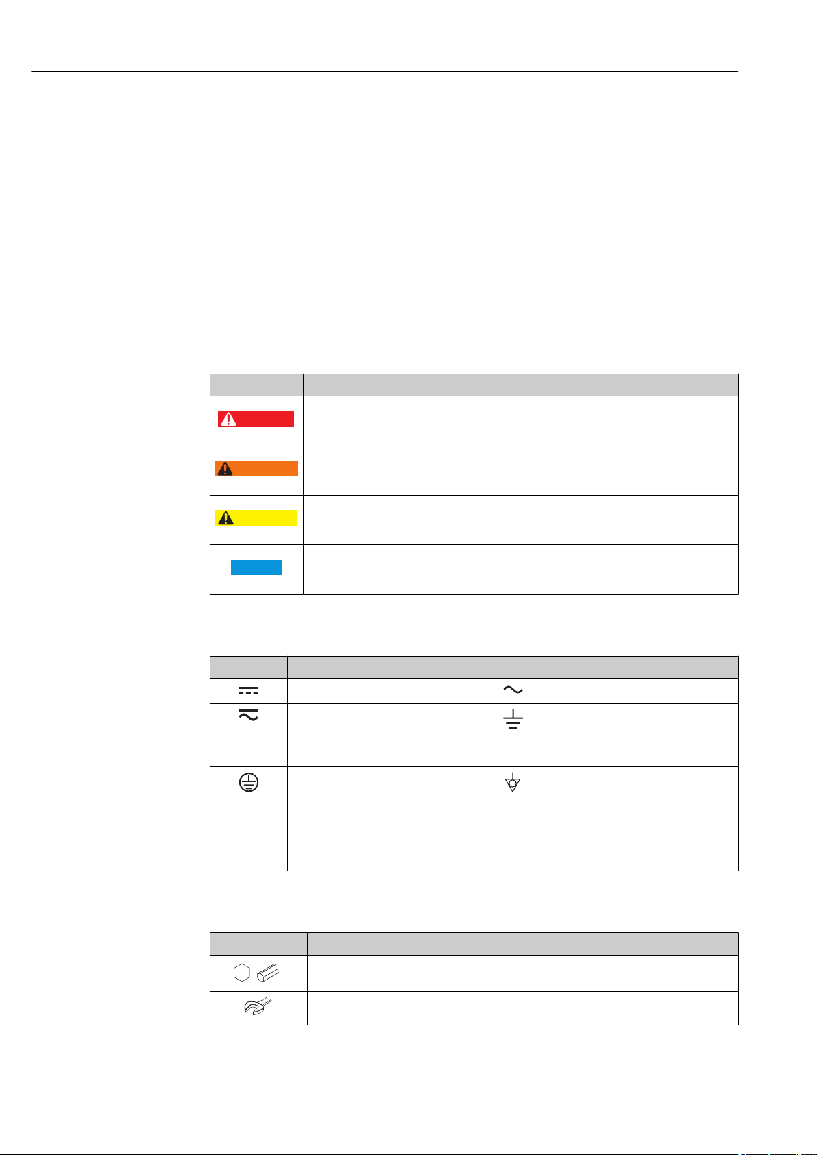
1.2.1 Safety symbols
Symbol Meaning
DANGER!
This symbol alerts you to a dangerous situation. Failure to avoid this situation will result in
serious or fatal injury.
WARNING!
This symbol alerts you to a dangerous situation. Failure to avoid this situation can result in
serious or fatal injury.
CAUTION!
This symbol alerts you to a dangerous situation. Failure to avoid this situation can result in
minor or medium injury.
NOTE!
This symbol contains information on procedures and other facts which do not result in
personal injury.
1.2.2 Electrical symbols
Symbol Meaning Symbol Meaning
Direct current Alternating current
Direct current and alternating current Ground connection
Protective ground connection
A terminal which must be connected
to ground prior to establishing any
other connections.
1.2.3 Tool symbols
Symbol Meaning
Allen key
Open-ended wrench
A grounded terminal which, as far as
the operator is concerned, is
grounded via a grounding system.
Equipotential connection
A connection that has to be connected
to the plant grounding system: This
may be a potential equalization line
or a star grounding system depending
on national or company codes of
practice.
6 Endress+Hauser
Proline Promass S 100 PROFINET Document information
,…,
,…,
-
.
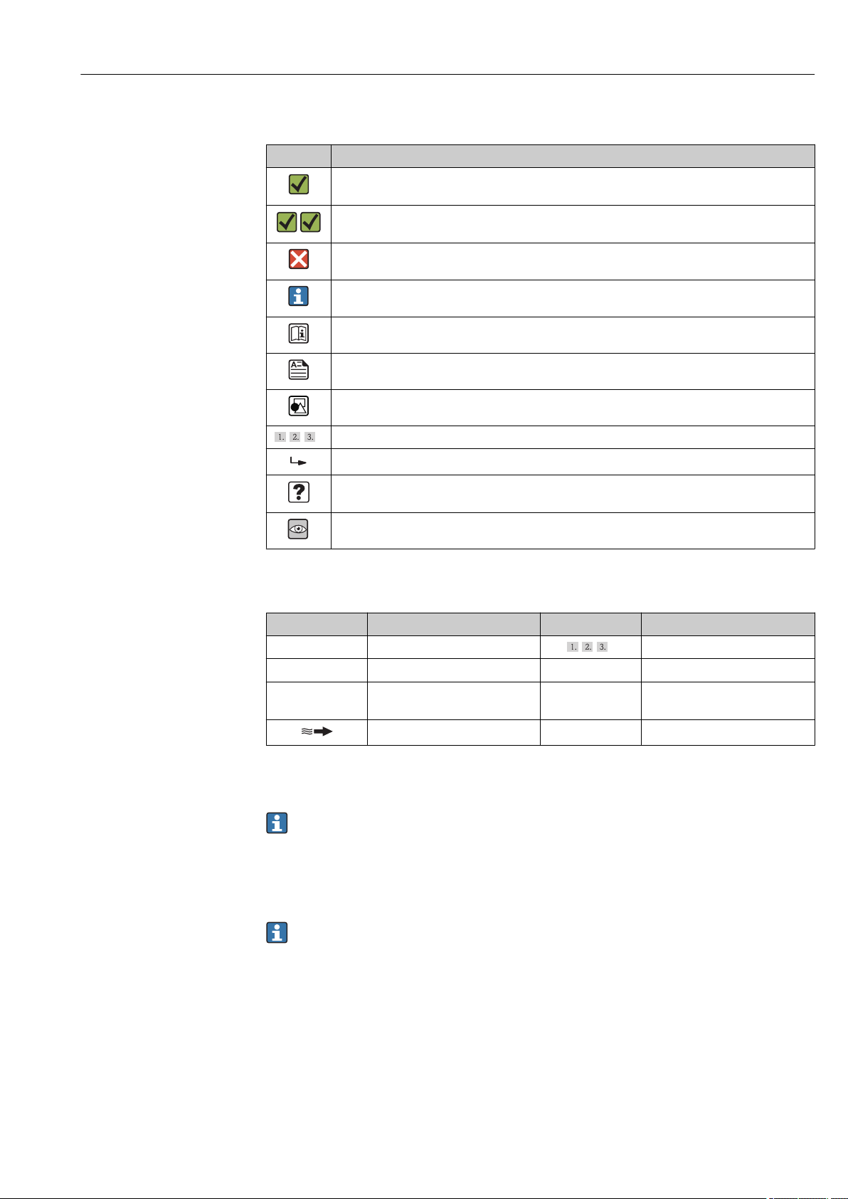
1.2.4 Symbols for certain types of information
Symbol Meaning
Permitted
Procedures, processes or actions that are permitted.
Preferred
Procedures, processes or actions that are preferred.
Forbidden
Procedures, processes or actions that are forbidden.
Tip
Indicates additional information.
Reference to documentation
Reference to page
Reference to graphic
Series of steps
Result of a step
Help in the event of a problem
Visual inspection
1.2.5 Symbols in graphics
Symbol Meaning Symbol Meaning
1, 2, 3,... Item numbers
A, B, C, ... Views A-A, B-B, C-C, ... Sections
Hazardous area
Flow direction
Series of steps
Safe area (non-hazardous area)
1.3 Documentation
For an overview of the scope of the associated Technical Documentation, refer to the
following:
• The W@M Device Viewer : Enter the serial number from the nameplate
(www.endress.com/deviceviewer)
• The Endress+Hauser Operations App: Enter the serial number from the nameplate
or scan the 2-D matrix code (QR code) on the nameplate.
For a detailed list of the individual documents along with the documentation code
Endress+Hauser 7

Document information Proline Promass S 100 PROFINET
1.3.1 Standard documentation
Document type Purpose and content of the document
Technical Information Planning aid for your device
The document contains all the technical data on the device and provides
an overview of the accessories and other products that can be ordered for
the device.
Brief Operating Instructions Guide that takes you quickly to the 1st measured value
The Brief Operating Instructions contain all the essential information
from incoming acceptance to initial commissioning.
1.3.2 Supplementary device-dependent documentation
Additional documents are supplied depending on the device version ordered: Always
comply strictly with the instructions in the supplementary documentation. The
supplementary documentation is an integral part of the device documentation.
1.4 Registered trademarks
PROFINET
Registered trademark of the PROFIBUS User Organization, Karlsruhe, Germany
Microsoft
Registered trademark of the Microsoft Corporation, Redmond, Washington, USA
TRI-CLAMP
Registered trademark of Ladish & Co., Inc., Kenosha, USA
®
®
®
Applicator®, FieldCare®, DeviceCare ®, Field XpertTM, HistoROM®, TMB®, Heartbeat
Technology
TM
Registered or registration-pending trademarks of the Endress+Hauser Group
8 Endress+Hauser

Proline Promass S 100 PROFINET Basic safety instructions
2 Basic safety instructions
2.1 Requirements for the personnel
The personnel for installation, commissioning, diagnostics and maintenance must fulfill
the following requirements:
Trained, qualified specialists must have a relevant qualification for this specific function
‣
and task
Are authorized by the plant owner/operator
‣
Are familiar with federal/national regulations
‣
Before beginning work, the specialist staff must have read and understood the
‣
instructions in the Operating Instructions and supplementary documentation as well as
in the certificates (depending on the application)
Following instructions and basic conditions
‣
The operating personnel must fulfill the following requirements:
Being instructed and authorized according to the requirements of the task by the
‣
facility's owner-operator
Following the instructions in these Operating Instructions
‣
2.2 Designated use
Application and media
The measuring device described in these Instructions is intended only for flow
measurement of liquids and gases.
Depending on the version ordered, the measuring device can also measure potentially
explosive, flammable, poisonous and oxidizing media.
Measuring devices for use in hazardous areas, in hygienic applications or in applications
where there is an increased risk due to process pressure, are labeled accordingly on the
nameplate.
To ensure that the measuring device remains in proper condition for the operation time:
Only use the measuring device in full compliance with the data on the nameplate and
‣
the general conditions listed in the Operating Instructions and supplementary
documentation.
Check the nameplate to verify if the device ordered can be put to its intended use in the
‣
approval-related area (e.g. explosion protection, pressure vessel safety).
Use the measuring device only for media against which the process-wetted materials
‣
are adequately resistant.
If the measuring device is not operated at atmospheric temperature, compliance with
‣
the relevant basic conditions specified in the associated device documentation is
absolutely essential: "Documentation" section → 7.
Protect the measuring device permanently against corrosion from environmental
‣
influences.
Incorrect use
Non-designated use can compromise safety. The manufacturer is not liable for damage
caused by improper or non-designated use.
WARNING
L
Danger of breakage of the measuring tube due to corrosive or abrasive fluids or from
environmental conditions.
Housing breakage due to mechanical overload possible!
Verify the compatibility of the process fluid with the measuring tube material.
‣
Ensure the resistance of all fluid-wetted materials in the process.
‣
Keep within the specified pressure and temperature range.
‣
Endress+Hauser 9

Basic safety instructions Proline Promass S 100 PROFINET
Verification for borderline cases:
For special fluids and fluids for cleaning, Endress+Hauser is glad to provide assistance
‣
in verifying the corrosion resistance of fluid-wetted materials, but does not accept any
warranty or liability as minute changes in the temperature, concentration or level of
contamination in the process can alter the corrosion resistance properties.
Residual risks
The external surface temperature of the housing can increase by max. 20 K due to the
power consumption of the electronic components. Hot process fluids passing through the
measuring device will further increase the surface temperature of the housing. The surface
of the sensor, in particular, can reach temperatures which are close to the fluid
temperature.
Possible burn hazard due to fluid temperatures!
For elevated fluid temperature, ensure protection against contact to prevent burns.
‣
2.3 Workplace safety
For work on and with the device:
Wear the required personal protective equipment according to federal/national
‣
regulations.
For welding work on the piping:
Do not ground the welding unit via the measuring device.
‣
If working on and with the device with wet hands:
It is recommended to wear gloves on account of the higher risk of electric shock.
‣
2.4 Operational safety
Risk of injury.
Operate the device in proper technical condition and fail-safe condition only.
‣
The operator is responsible for interference-free operation of the device.
‣
Conversions to the device
Unauthorized modifications to the device are not permitted and can lead to unforeseeable
dangers.
If, despite this, modifications are required, consult with Endress+Hauser.
‣
Repair
To ensure continued operational safety and reliability,
Carry out repairs on the device only if they are expressly permitted.
‣
Observe federal/national regulations pertaining to repair of an electrical device.
‣
Use original spare parts and accessories from Endress+Hauser only.
‣
2.5 Product safety
This measuring device is designed in accordance with good engineering practice to meet
state-of-the-art safety requirements, has been tested, and left the factory in a condition in
which it is safe to operate.
It meets general safety standards and legal requirements. It also complies with the EC
directives listed in the device-specific EC Declaration of Conformity. Endress+Hauser
confirms this by affixing the CE mark to the device.
10 Endress+Hauser

Proline Promass S 100 PROFINET Basic safety instructions
2.6 IT security
We only provide a warranty if the device is installed and used as described in the
Operating Instructions. The device is equipped with security mechanisms to protect it
against any inadvertent changes to the device settings.
IT security measures in line with operators' security standards and designed to provide
additional protection for the device and device data transfer must be implemented by the
operators themselves.
Endress+Hauser 11
Product description Proline Promass S 100 PROFINET
3
2
1
4
5
6
7
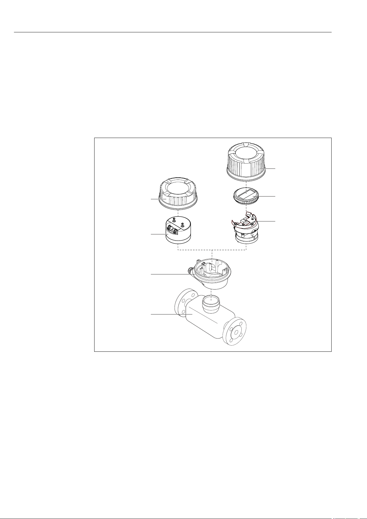
3 Product description
The device consists of a transmitter and a sensor.
The device is available as a compact version:
The transmitter and sensor form a mechanical unit.
3.1 Product design
3.1.1 Device version with PROFINET communication type
1 Important components of a measuring device
1 Sensor
2 Transmitter housing
3 Main electronics module
4 Transmitter housing cover
5 Transmitter housing cover (version for optional onsite display)
6 Onsite display (optional)
7 Main electronics module (with bracket for optional onsite display)
12 Endress+Hauser
A0023153
Proline Promass S 100 PROFINET Incoming acceptance and product identification
1
+
2
1
+
2
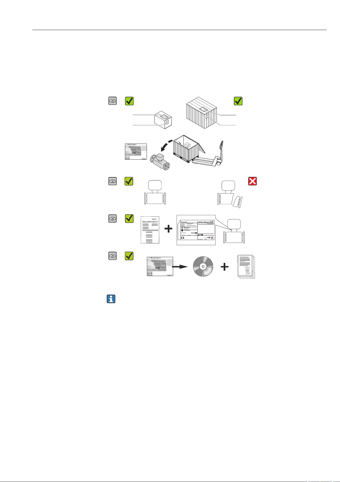
4 Incoming acceptance and product
identification
4.1 Incoming acceptance
Are the order codes on the
delivery note (1) and the
product sticker (2)
identical?
Are the goods undamaged?
Do the nameplate data
match the ordering
information on the delivery
note?
Is the CD-ROM with the
Technical Documentation
(depends on device
version) and documents
present?
• If one of the conditions is not satisfied, contact your Endress+Hauser Sales Center.
• Depending on the device version, the CD-ROM might not be part of the delivery!
The Technical Documentation is available via the Internet or via the Endress+Hauser
Operations App, see the "Product identification" section → 14.
4.2 Product identification
The following options are available for identification of the measuring device:
• Nameplate specifications
• Order code with breakdown of the device features on the delivery note
• Enter serial numbers from nameplates in W@M Device Viewer
(www.endress.com/deviceviewer): All information about the measuring device is
displayed.
• Enter the serial number from the nameplates into the Endress+Hauser Operations App
or scan the 2-D matrix code (QR code) on the nameplate with the Endress+Hauser
Operations App: all the information for the measuring device is displayed.
Endress+Hauser 13
Incoming acceptance and product identification Proline Promass S 100 PROFINET
i
1
2
3
4
5
6
7
8
9
101112
Order code:
Ext. ord. cd.:
Ser. no.:
13
For an overview of the scope of the associated Technical Documentation, refer to the
following:
• The chapters "Additional standard documentation on the device" → 8 and
"Supplementary device-dependent documentation" → 8
• The W@M Device Viewer: Enter the serial number from the nameplate
(www.endress.com/deviceviewer)
• The Endress+Hauser Operations App: Enter the serial number from the nameplate or
scan the 2-D matrix code (QR code) on the nameplate.
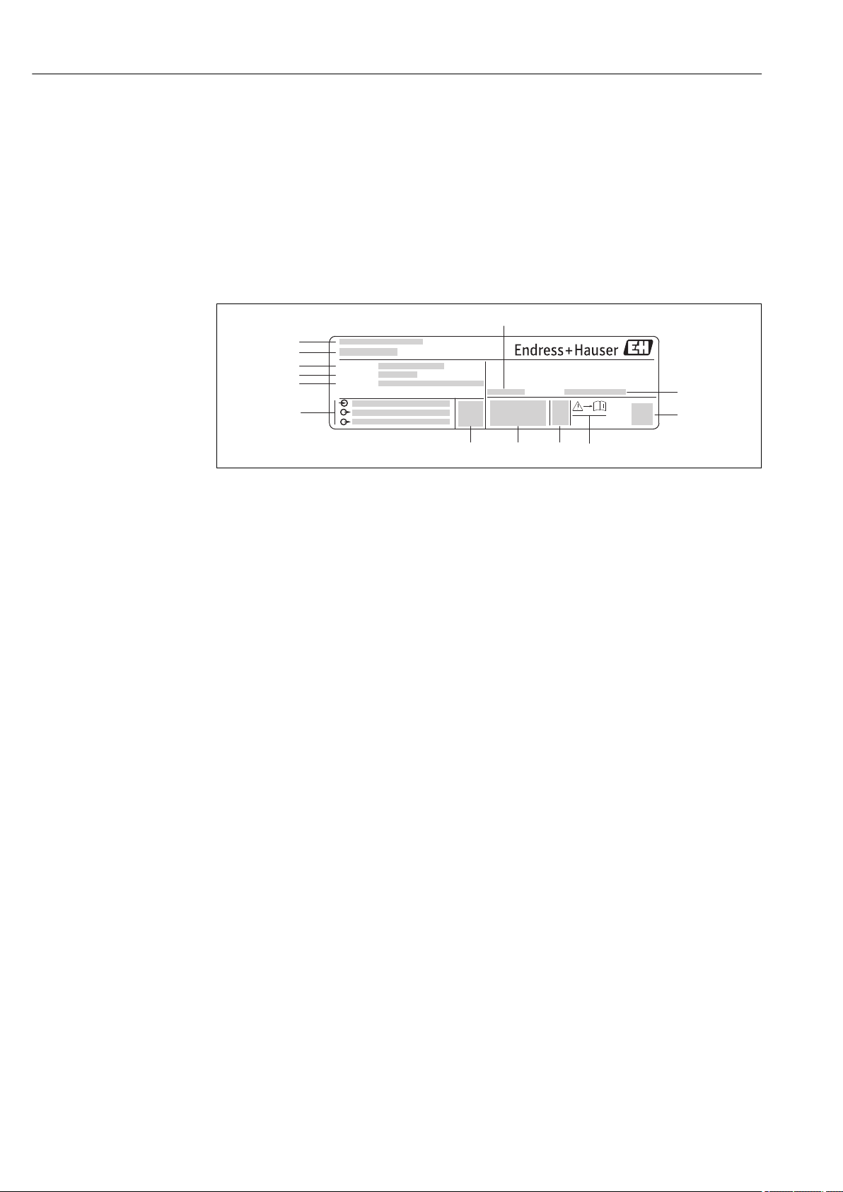
4.2.1 Transmitter nameplate
2 Example of a transmitter nameplate
1 Manufacturing location
2 Name of the transmitter
3 Order code
4 Serial number (Ser. no.)
5 Extended order code (Ext. ord. cd.)
6 Electrical connection data, e.g. available inputs and outputs, supply voltage
7 Permitted ambient temperature (Ta)
8 Degree of protection
9 2-D matrix code
10 Document number of safety-related supplementary documentation
11 Manufacturing date: year-month
12 CE mark, C-Tick
13 Firmware version (FW)
A0017520
14 Endress+Hauser
Proline Promass S 100 PROFINET Incoming acceptance and product identification
Ext. ord. cd.:
Order code:
Ser. no.:
Material:
Tm:
Size:
Ta:
Date:
6
10
11
1 2
3
4
5
Ptest:
7
8
12
Patents
16
17
19
18
13
15
9
14
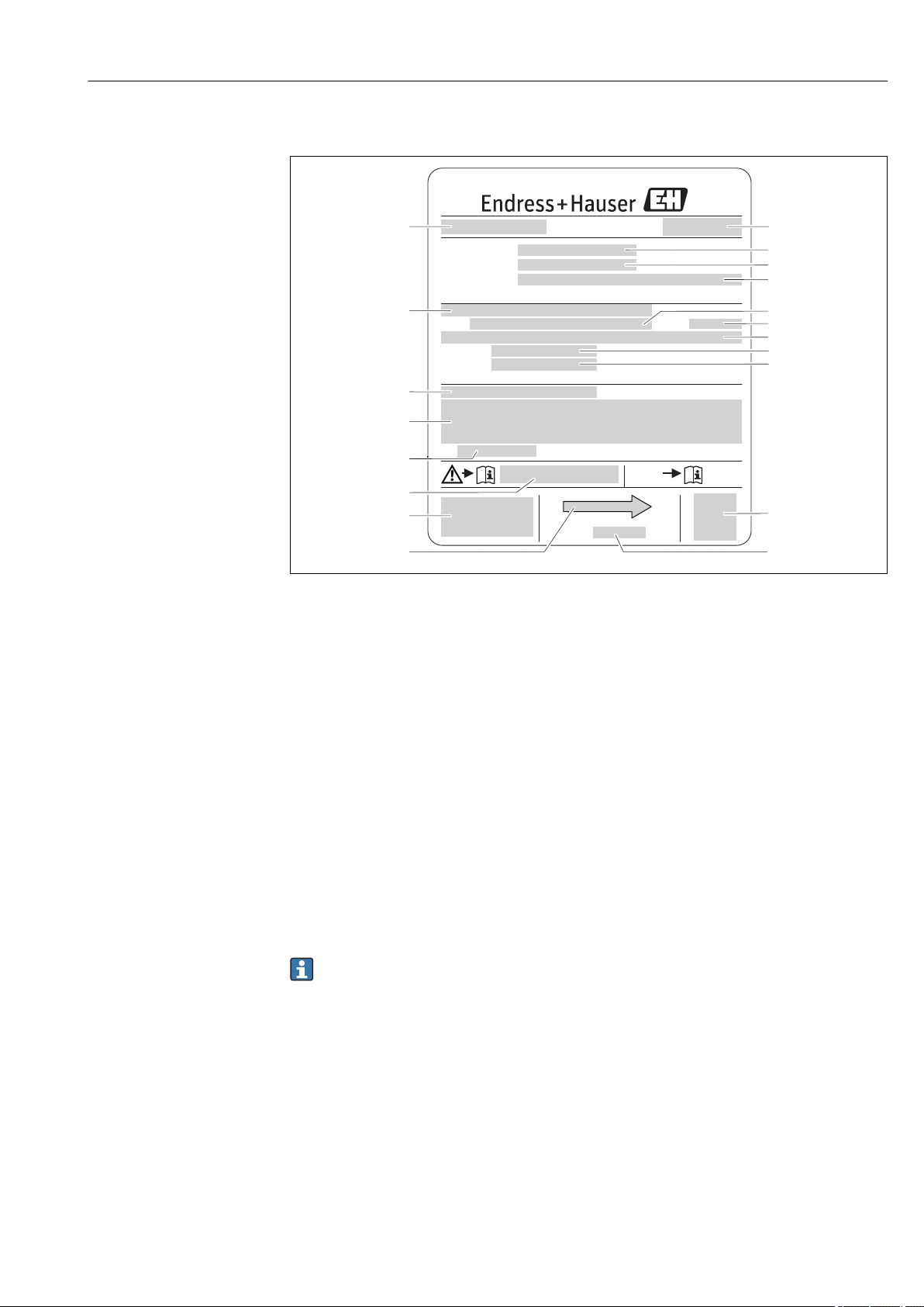
4.2.2 Sensor nameplate
3 Example of a sensor nameplate
1 Name of the sensor
2 Manufacturing location
3 Order code
4 Serial number (ser. no.)
5 Extended order code (ext. ord. cd.)
6 Flange nominal diameter/nominal pressure
7 Test pressure of the sensor
8 Nominal diameter of sensor
9 Sensor-specific data: e.g. pressure range of secondary containment, wide-range density specification (special
density calibration)
10 Material of measuring tube and manifold
11 Medium temperature range
12 Degree of protection
13 Approval information for explosion protection and Pressure Equipment Directive
14 Permitted ambient temperature (Ta)
15 Document number of safety-related supplementary documentation
16 CE mark, C-Tick
17 Flow direction
18 Manufacturing date: year-month
19 2-D matrix code
Order code
The measuring device is reordered using the order code.
Extended order code
• The device type (product root) and basic specifications (mandatory features) are
always listed.
• Of the optional specifications (optional features), only the safety and approvalrelated specifications are listed (e.g. LA). If other optional specifications are also
ordered, these are indicated collectively using the # placeholder symbol (e.g. #LA#).
• If the ordered optional specifications do not include any safety and approval-related
specifications, they are indicated by the + placeholder symbol (e.g. XXXXXX-ABCDE
+).
A0017923
Endress+Hauser 15

Incoming acceptance and product identification Proline Promass S 100 PROFINET
4.2.3 Symbols on measuring device
Symbol Meaning
WARNING!
This symbol alerts you to a dangerous situation. Failure to avoid this situation can result in serious
or fatal injury.
Reference to documentation
Refers to the corresponding device documentation.
Protective ground connection
A terminal which must be connected to ground prior to establishing any other connections.
16 Endress+Hauser
Proline Promass S 100 PROFINET Storage and transport
5 Storage and transport
5.1 Storage conditions
Observe the following notes for storage:
• Store in the original packaging to ensure protection from shock.
• Do not remove protective covers or protective caps installed on process connections.
They prevent mechanical damage to the sealing surfaces and contamination in the
measuring tube.
• Protect from direct sunlight to avoid unacceptably high surface temperatures.
• Store in a dry and dust-free place.
• Do not store outdoors.
Storage temperature: –40 to +80 °C (–40 to +176 °F),
Order code for "Test, Certificate", option JM: –50 to +60 °C (–58 to +140 °F),
preferably at +20 °C (+68 °F)
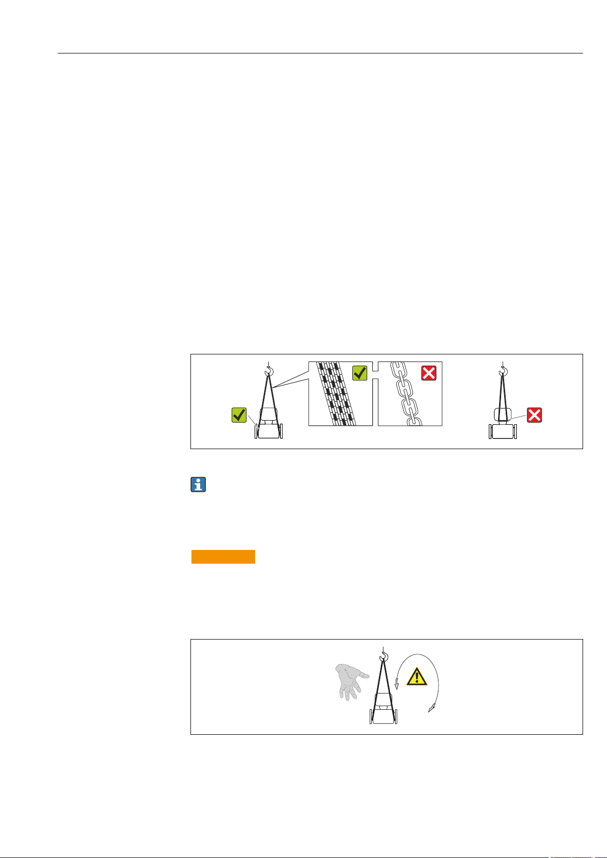
5.2 Transporting the product
Transport the measuring device to the measuring point in the original packaging.
A0015604
Do not remove protective covers or caps installed on process connections. They
prevent mechanical damage to the sealing surfaces and contamination in the
measuring tube.
5.2.1 Measuring devices without lifting lugs
WARNING
L
Center of gravity of the measuring device is higher than the suspension points of the
webbing slings.
Risk of injury if the measuring device slips.
Secure the measuring device against slipping or turning.
‣
Observe the weight specified on the packaging (stick-on label).
‣
A0015606
Endress+Hauser 17

Storage and transport Proline Promass S 100 PROFINET
5.2.2 Measuring devices with lifting lugs
CAUTION
L
Special transportation instructions for devices with lifting lugs
Only use the lifting lugs fitted on the device or flanges to transport the device.
‣
The device must always be secured at two lifting lugs at least.
‣
5.2.3 Transporting with a fork lift
If transporting in wood crates, the floor structure enables the crates to be lifted lengthwise
or at both sides using a forklift.
5.3 Packaging disposal
All packaging materials are environmentally friendly and 100% recyclable:
• Measuring device secondary packaging: polymer stretch film that conforms to EC
Directive 2002/95/EC (RoHS).
• Packaging:
– Wood crate, treated in accordance with ISPM 15 standard, which is confirmed by the
affixed IPPC logo.
or
– Carton in accordance with European Packaging Directive 94/62EC; recyclability is
confirmed by the affixed RESY symbol.
• Seaworthy packaging (optional): Wood crate, treated in accordance with ISPM 15
standard, which is confirmed by the affixed IPPC logo.
• Carrying and mounting hardware:
– Disposable plastic pallet
– Plastic straps
– Plastic adhesive strips
• Dunnage: Paper cushion
18 Endress+Hauser
Proline Promass S 100 PROFINET Installation
1
2
3
4
5
6 Installation
6.1 Installation conditions
No special measures such as supports are necessary. External forces are absorbed by the
construction of the device.
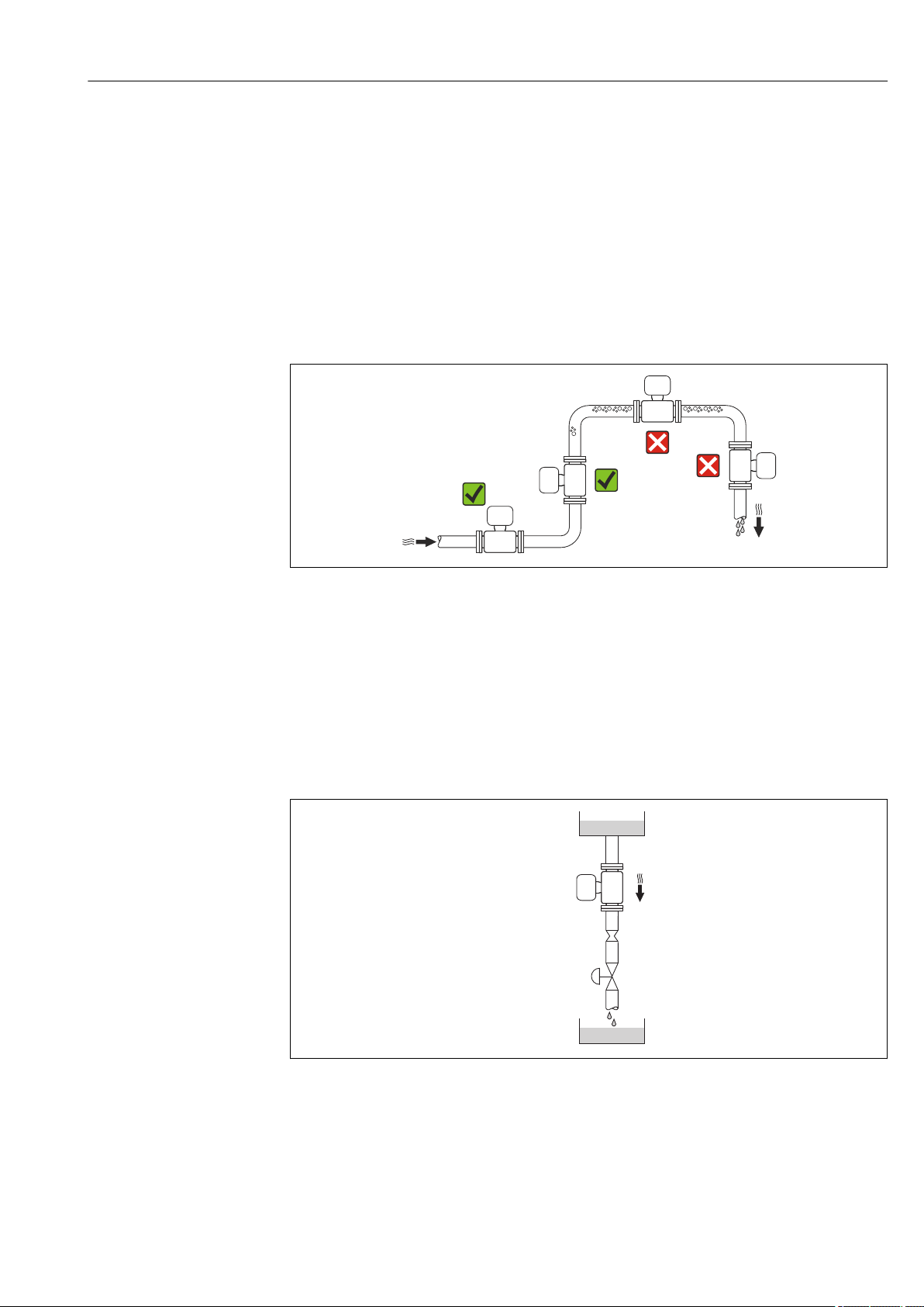
6.1.1 Mounting position
Mounting location
To prevent measuring errors arising from accumulation of gas bubbles in the measuring
tube, avoid the following mounting locations in the pipe:
• Highest point of a pipeline.
• Directly upstream of a free pipe outlet in a down pipe.
Installation in down pipes
However, the following installation suggestion allows for installation in an open vertical
pipeline. Pipe restrictions or the use of an orifice with a smaller cross-section than the
nominal diameter prevent the sensor running empty while measurement is in progress.
A0023344
A0015596
4 Installation in a down pipe (e.g. for batching applications)
1 Supply tank
2 Sensor
3 Orifice plate, pipe restriction
4 Valve
5 Batching tank
Endress+Hauser 19
Installation Proline Promass S 100 PROFINET
1 2
DN Ø orifice plate, pipe restriction
[mm] [in] [mm] [in]
8 ³⁄₈ 6 0.24
15 ½ 10 0.40
25 1 14 0.55
40 1½ 22 0.87
50 2 28 1.10
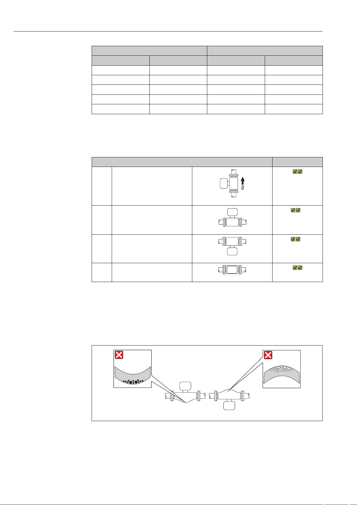
Orientation
The direction of the arrow on the sensor nameplate helps you to install the sensor
according to the flow direction (direction of medium flow through the piping).
Orientation Recommendation
A Vertical orientation
A0015591
B Horizontal orientation, transmitter
head up
1)
Exceptions:
→ 5, 20
A0015589
C Horizontal orientation, transmitter
head down
2)
Exceptions:
→ 5, 20
A0015590
D Horizontal orientation, transmitter
head at side
A0015592
1) Applications with low process temperatures may decrease the ambient temperature. To maintain the
minimum ambient temperature for the transmitter, this orientation is recommended.
2) Applications with high process temperatures may increase the ambient temperature. To maintain the
maximum ambient temperature for the transmitter, this orientation is recommended.
If a sensor is installed horizontally with a curved measuring tube, match the position of the
sensor to the fluid properties.
A0014057
5 Orientation of sensor with curved measuring tube
1 Avoid this orientation for fluids with entrained solids: Risk of solids accumulating.
2 Avoid this orientation for outgassing fluids: Risk of gas accumulating.
20 Endress+Hauser
Proline Promass S 100 PROFINET Installation
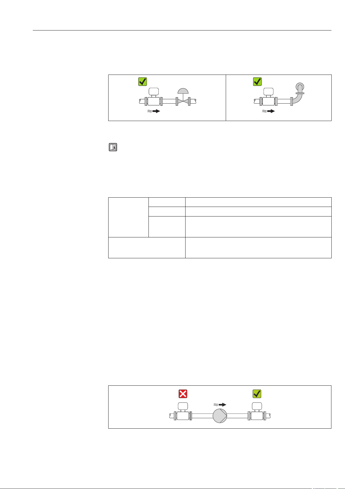
Inlet and outlet runs
No special precautions need to be taken for fittings which create turbulence, such as
valves, elbows or T-pieces, as long as no cavitation occurs → 21.
A0015597 A0015598
Installation dimensions
For the dimensions and installation lengths of the device, see the "Technical
Information" document, "Mechanical construction" section
6.1.2 Requirements from environment and process
Ambient temperature range
Measuring device Non-Ex –40 to +60 °C (–40 to +140 °F)
Ex na, NI version –40 to +60 °C (–40 to +140 °F)
Ex ia, IS version • –40 to +60 °C (–40 to +140 °F)
• –50 to +60 °C (–58 to +140 °F) (order code for "Test, certificate",
option JM))
Readability of the local display –20 to +60 °C (–4 to +140 °F)
The readability of the display may be impaired at temperatures outside
the temperature range.
If operating outdoors:
‣
Avoid direct sunlight, particularly in warm climatic regions.
System pressure
It is important that cavitation does not occur, or that gases entrained in the liquids do not
outgas.
Cavitation is caused if the pressure drops below the vapor pressure:
• In liquids that have a low boiling point (e.g. hydrocarbons, solvents, liquefied gases)
• In suction lines
Ensure the system pressure is sufficiently high to prevent cavitation and outgassing.
‣
For this reason, the following mounting locations are recommended:
• At the lowest point in a vertical pipe
• Downstream from pumps (no danger of vacuum)
A0015594
Endress+Hauser 21
Installation Proline Promass S 100 PROFINET
t
a
0
10
30
20
40
[mm][in]
80 90 100 110
[°C]
[°F]
200 250 290
0.5
1.0
1.5
0
T
40(104)
T
60(140)
t
120 130 140
T
m
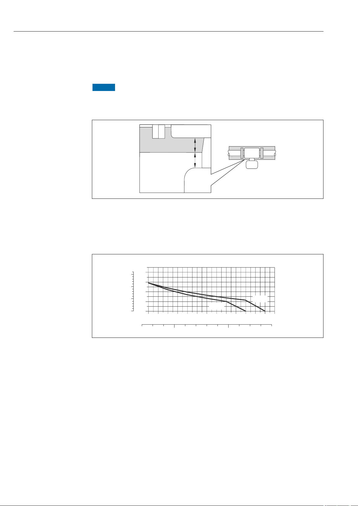
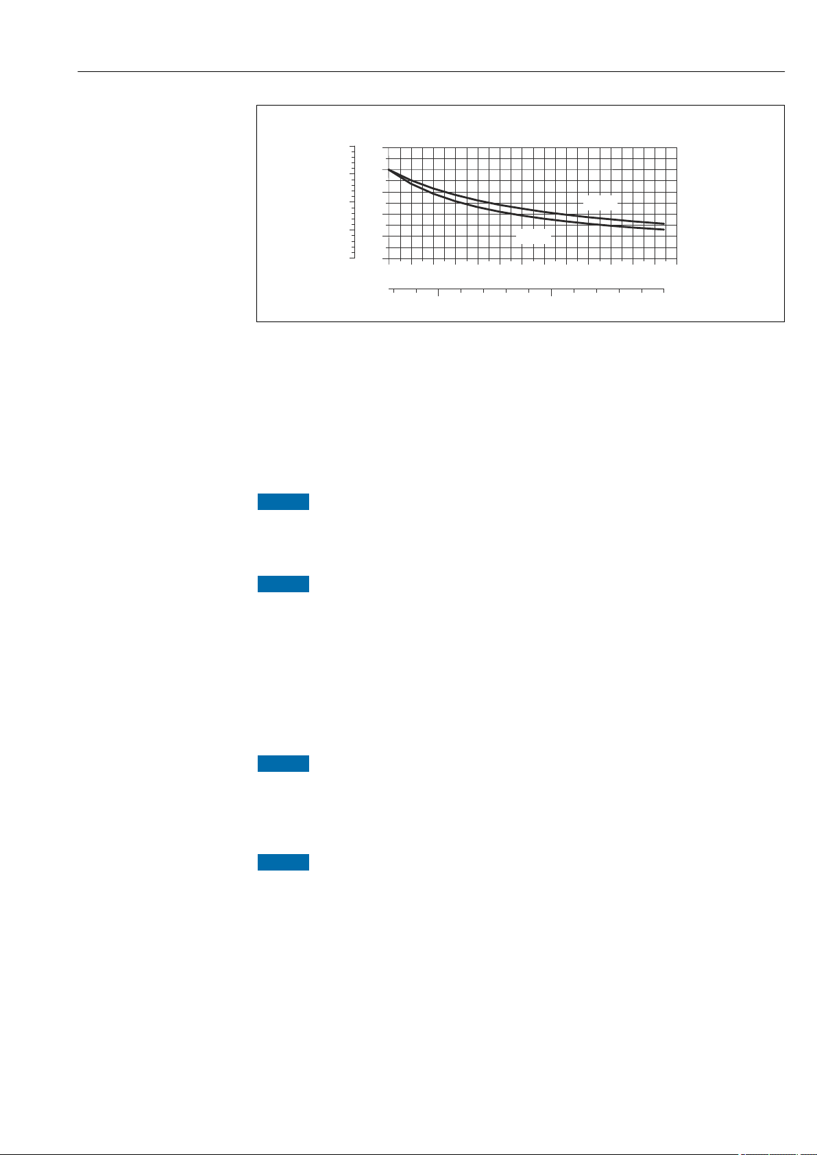
Thermal insulation
In the case of some fluids, it is important that the heat radiated from the sensor to the
transmitter is kept to a minimum. A wide range of materials can be used for the required
insulation.
NOTICE
Electronics overheating on account of thermal insulation!
Observe maximum permitted insulation height of the transmitter neck so that the
‣
transmitter head is completely free.
a Minimum distance to insulation
t maximum Insulation thickness
The minimum distance between the transmitter housing and the insulation is
10 mm (0.39 in) so that the transmitter head remains completely exposed.
Maximum recommended insulation thickness
6 Maximum recommended insulation thickness depending on the temperature of the medium and the
ambient temperature
t Insulation thickness
T
m
T
40(104)
T
60(140)
Medium temperature
Maximum recommended insulation thickness at an ambient temperature of Ta = 40 °C (104 °F)
Maximum recommended insulation thickness at an ambient temperature of Ta = 60 °C (140 °F)
A0019919
A0023173
Maximum recommended insulation thickness for the extended temperature range
and insulation
22 Endress+Hauser
For the extension neck for insulation version, order code for "Sensor option", option CG:
Proline Promass S 100 PROFINET Installation
0
20
60
40
80
[in]
1
2
3
0
t
100
4
[mm]
T
40(104)
T
60(140)
80 100 120 140
200 300 400
160 180 200
[°F]
T
m
[°C]
A0023177
7 Maximum recommended insulation thickness depending on the temperature of the medium and the
ambient temperature
t Insulation thickness
T
m
T
40(104)
T
60(140)
Medium temperature
Maximum recommended insulation thickness at an ambient temperature of Ta = 40 °C (104 °F)
Maximum recommended insulation thickness at an ambient temperature of Ta = 60 °C (140 °F)
Endress+Hauser 23
Danger of overheating with insulation
‣
The insulation can also be thicker than the maximum recommended insulation
thickness.
Prerequisite:
‣
‣
Heating
Electronics can overheat due to elevated ambient temperature!
‣
‣
Danger of overheating when heating
‣
‣
‣
NOTICE
Ensure that the temperature at the lower end of the transmitter housing does not
exceed 80 °C (176 °F)
NOTICE
Ensure that convection takes place on a sufficiently large scale at the transmitter neck.
Ensure that a sufficiently large area of the housing support remains exposed. The
uncovered part serves as a radiator and protects the electronics from overheating and
excessive cooling.
NOTICE
Observe maximum permitted ambient temperature for the transmitter .
Depending on the fluid temperature, take the device orientation requirements into
account .
NOTICE
Ensure that the temperature at the lower end of the transmitter housing does not
exceed 80 °C (176 °F)
Ensure that convection takes place on a sufficiently large scale at the transmitter neck.
Ensure that a sufficiently large area of the housing support remains exposed. The
uncovered part serves as a radiator and protects the electronics from overheating and
excessive cooling.
Installation Proline Promass S 100 PROFINET
A
B
C
Heating options
If a fluid requires that no heat loss should occur at the sensor, users can avail of the
following heating options:
• Electrical heating, e.g. with electric band heaters
• Via pipes carrying hot water or steam
• Via heating jackets
Using an electrical trace heating system
If heating is regulated via phase angle control or pulse packages, magnetic fields can affect
the measured values (= for values that are greater than the values approved by the EN
standard (sine 30 A/m)).
For this reason, the sensor must be magnetically shielded: the housing can be shielded
with tin plates or electric sheets without a privileged direction (e.g. V330-35A).
The sheet must have the following properties:
• Relative magnetic permeability µr ≥ 300
• Plate thickness d ≥ 0.35 mm (d ≥ 0.014 in)
Vibrations
The high oscillation frequency of the measuring tubes ensures that the correct operation of
the measuring system is not influenced by plant vibrations.
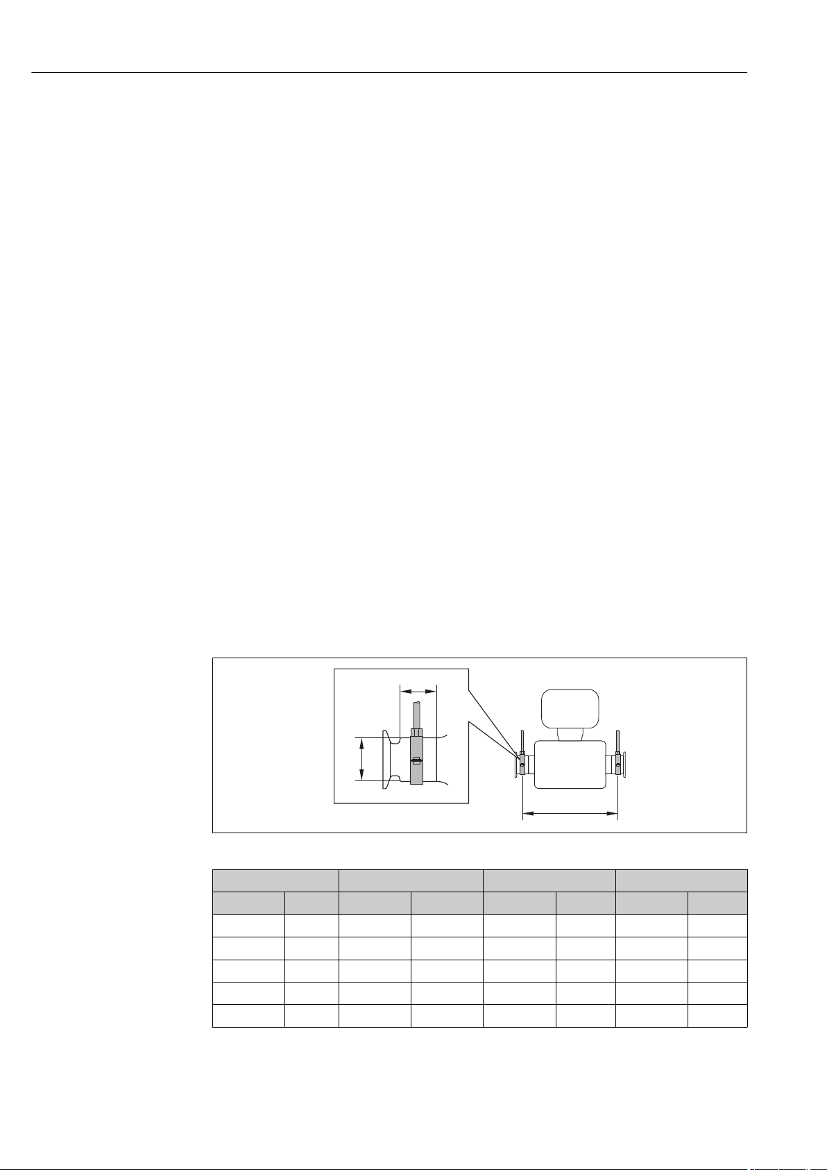
6.1.3 Special mounting instructions
Securing with mounting clamp in the case of hygiene connections
It is not necessary to provide additional support for the sensor for operational performance
purposes. If, however, additional support is required for installation purposes, the
following dimensions must be observed.
Use mounting clamp with lining between clamp and measuring instrument.
A0016588
DN A B C
[mm] [in] [mm] [in] [mm] [in] [mm] [in]
8 ³⁄₈ 298 11.73 33 1.3 28 1.1
15 ½ 402 15.83 33 1.3 28 1.1
25 1 542 21.34 33 1.3 38 1.5
40 1 ½ 658 25.91 36.5 1.44 56 2.2
50 2 772 30.39 44.1 1.74 75 2.95
24 Endress+Hauser
Proline Promass S 100 PROFINET Installation
Zero point adjustment
All measuring devices are calibrated in accordance with state-of-the-art technology.
Calibration takes place under reference conditions → 125. Therefore, a zero point
adjustment in the field is generally not required.
Experience shows that zero point adjustment is advisable only in special cases:
• To achieve maximum measuring accuracy even with low flow rates
• Under extreme process or operating conditions (e.g. very high process temperatures or
very high-viscosity fluids).
6.2 Mounting the measuring device
6.2.1 Required tools
For sensor
For flanges and other process connections: Corresponding mounting tools
6.2.2 Preparing the measuring device
1. Remove all remaining transport packaging.
2. Remove any protective covers or protective caps present from the sensor.
3. Remove stick-on label on the electronics compartment cover.
6.2.3 Mounting the measuring device
WARNING
L
Danger due to improper process sealing!
Ensure that the inside diameters of the gaskets are greater than or equal to that of the
‣
process connections and piping.
Ensure that the gaskets are clean and undamaged.
‣
Install the gaskets correctly.
‣
1. Ensure that the direction of the arrow on the nameplate of the sensor matches the
flow direction of the fluid.
2. Install the measuring device or turn the transmitter housing so that the cable entries
do not point upwards.
A0013964
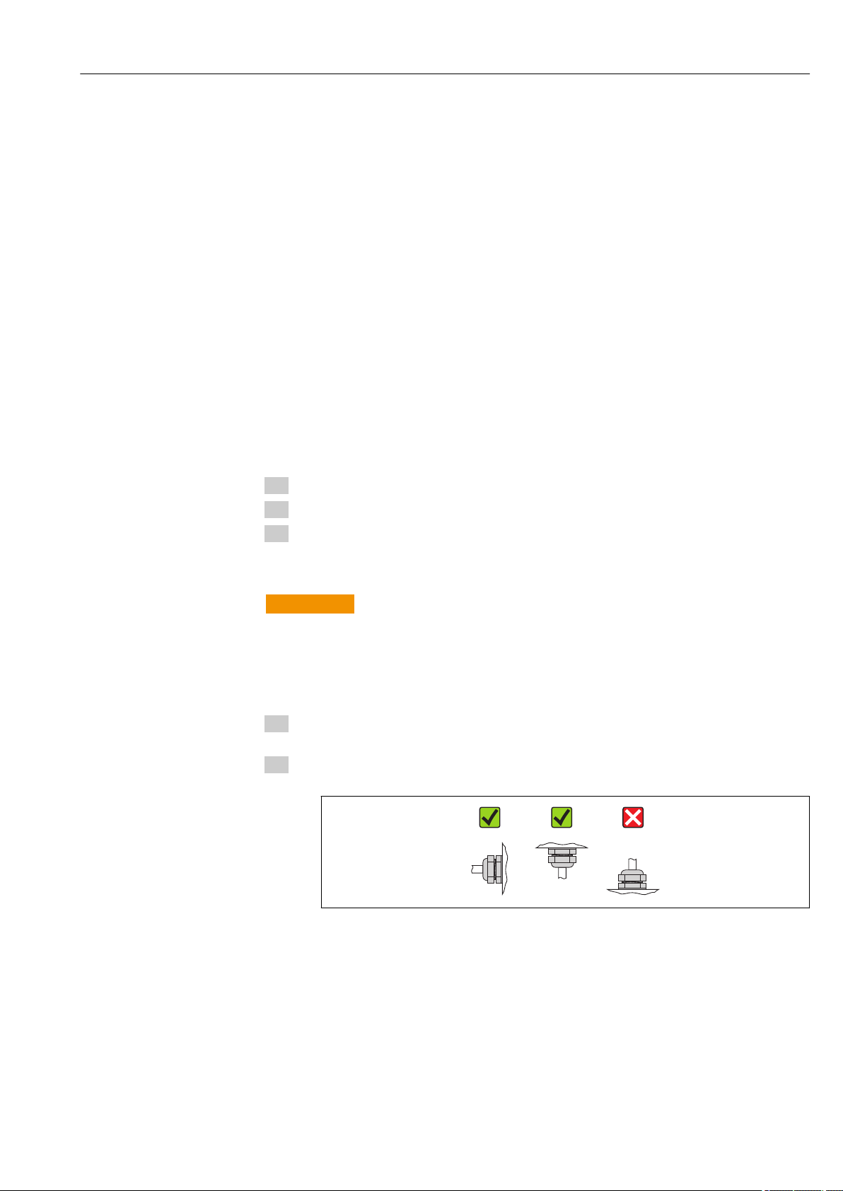
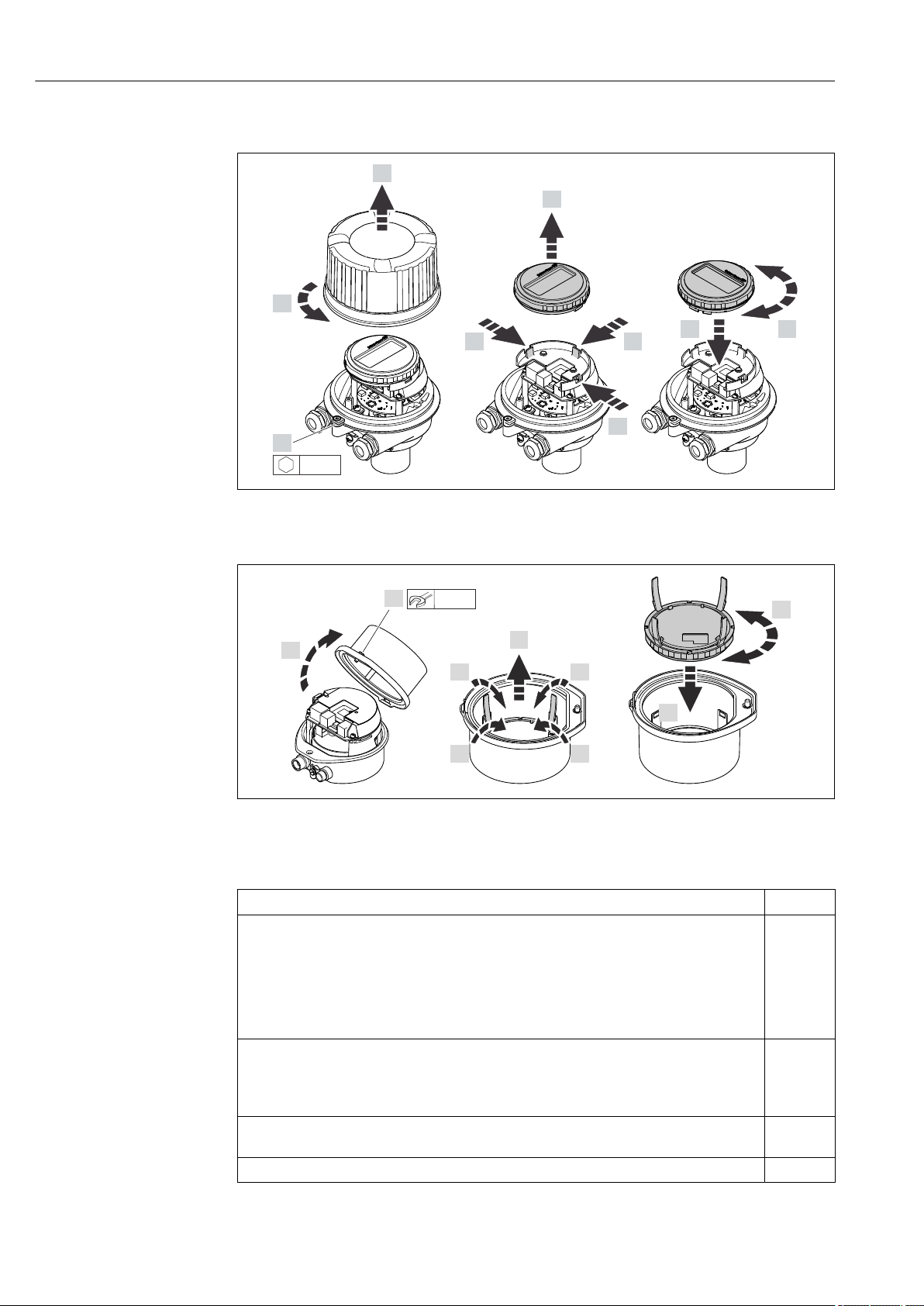
6.2.4 Turning the display module
The local display is only available with the following device version:
Order code for "Display; Operation", option B: 4-line; lit, via communication
The display module can be turned to optimize display readability.
Endress+Hauser 25
Installation Proline Promass S 100 PROFINET
1.
2.
3.
4.
5.
6.
7.
4.
4.
3 mm
1.
2.
3.
4.
5.
6.
3.
3. 3.
8 mm
Aluminum housing version, AlSi10Mg, coated
A0023192
Compact and ultra-compact housing version, hygienic, stainless
A0023195
6.3 Post-installation check
Is the device undamaged (visual inspection)?
Does the measuring device conform to the measuring point specifications?
For example:
• Process temperature → 129
• Process pressure (refer to the chapter on "Pressure-temperature ratings" of the "Technical
Information" document)
• Ambient temperature
• Measuring range
Has the correct orientation for the sensor been selected ?
• According to sensor type
• According to medium temperature
• According to medium properties (outgassing, with entrained solids)
Does the arrow on the sensor nameplate match the direction of flow of the fluid through the
piping → 20?
Are the measuring point identification and labeling correct (visual inspection)?
26 Endress+Hauser

Proline Promass S 100 PROFINET Installation
Is the device adequately protected from precipitation and direct sunlight?
Are the securing screw and securing clamp tightened securely?
Endress+Hauser 27

Electrical connection Proline Promass S 100 PROFINET
7 Electrical connection
The measuring device does not have an internal circuit breaker. For this reason,
assign the measuring device a switch or power-circuit breaker so that the power
supply line can be easily disconnected from the mains.
7.1 Connection conditions
7.1.1 Required tools
• For cable entries: Use corresponding tools
• For securing clamp (on aluminum housing): Allen screw3 mm
• For securing screw (for stainless steel housing): open-ended wrench 8 mm
• Wire stripper
• When using stranded cables: crimping tool for ferrule
7.1.2 Requirements for connecting cable
The connecting cables provided by the customer must fulfill the following requirements.
Electrical safety
In accordance with applicable federal/national regulations.
Permitted temperature range
• –40 °C (–40 °F) to +80 °C (+176 °F)
• Minimum requirement: cable temperature range ≥ ambient temperature +20 K
Power supply cable
Standard installation cable is sufficient.
Signal cable
PROFINET
Standard IEC 61156-6 specifies CAT 5 as the minimum category for a cable used for
PROFINET. CAT 5e and CAT 6 are recommended.
For more information on planning and installing PROFINET networks, see: "PROFINET
Cabling and Interconnection Technology", Guideline for PROFINET
Cable diameter
• Cable glands supplied:
M20 × 1.5 with cable 6 to 12 mm (0.24 to 0.47 in)
• Spring terminals:
Wire cross-sections 0.5 to 2.5 mm2 (20 to 14 AWG)
28 Endress+Hauser
Proline Promass S 100 PROFINET Electrical connection
L
L
1
2
+
_
1
2
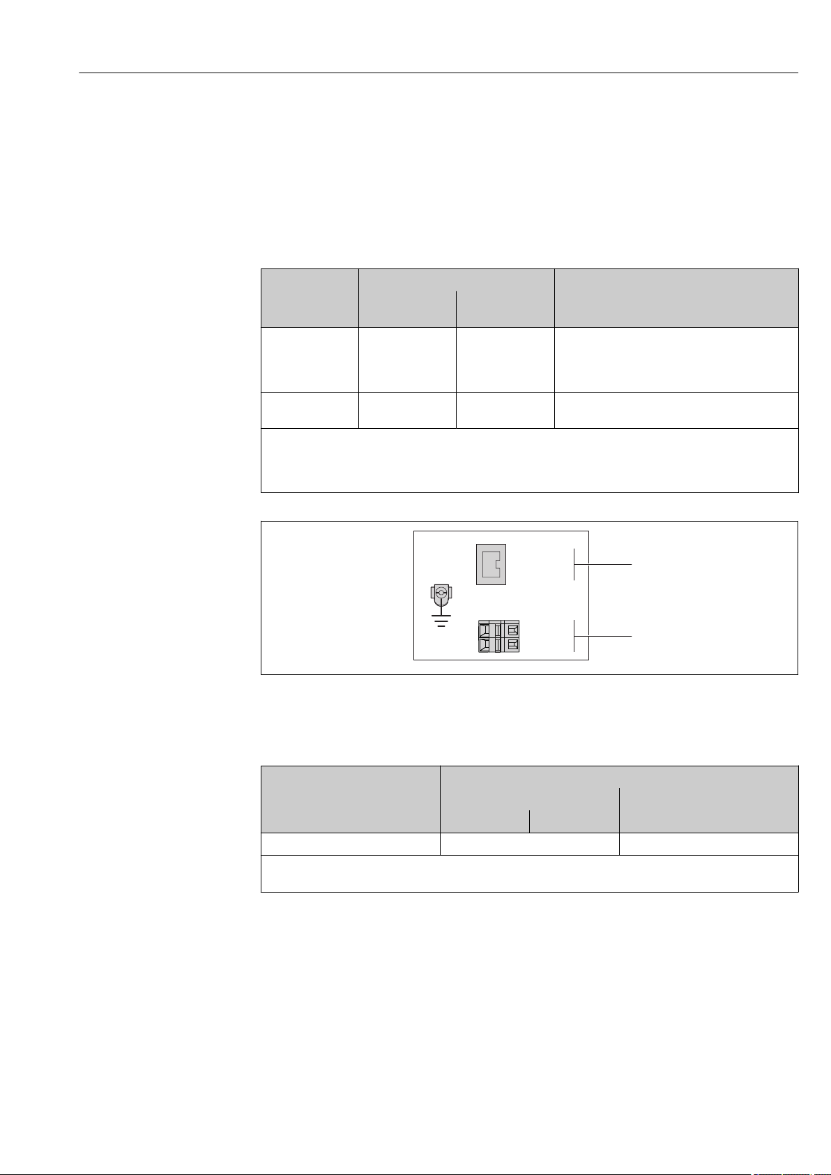
7.1.3 Terminal assignment
Transmitter
PROFINET connection version
Order code for "Output", option R
Depending on the housing version, the transmitters can be ordered with terminals or
device plugs.
Order code for
"Housing"
Options
A, B
Options
A, B, C
Order code for "Housing":
• Option A: compact, coated aluminum
• Option B: compact, hygienic, stainless
• Option C ultra-compact, hygienic, stainless
8 PROFINET terminal assignment
1 Power supply: DC 24 V
2 PROFINET
Connection methods available
Output
Device plugs
→ 30
Device plugs
→ 30
Power
supply
Terminals • Option L: plug M12x1 + thread NPT ½"
Device plugs
→ 30
Possible options for order code
"Electrical connection"
• Option N: plug M12x1 + coupling M20
• Option P: plug M12x1 + thread G ½"
• Option U: plug M12x1 + thread M20
Option Q: 2 x plug M12x1
A0017054
Terminal number
Order code for
"Output"
Option R DC 24 V PROFINET
Order code for "Output":
Option R: PROFINET
Power supply Output
2 (L-) 1 (L+) Device plug M12x1
Endress+Hauser 29
Electrical connection Proline Promass S 100 PROFINET
1
2
4
3
5
3
2
4
1
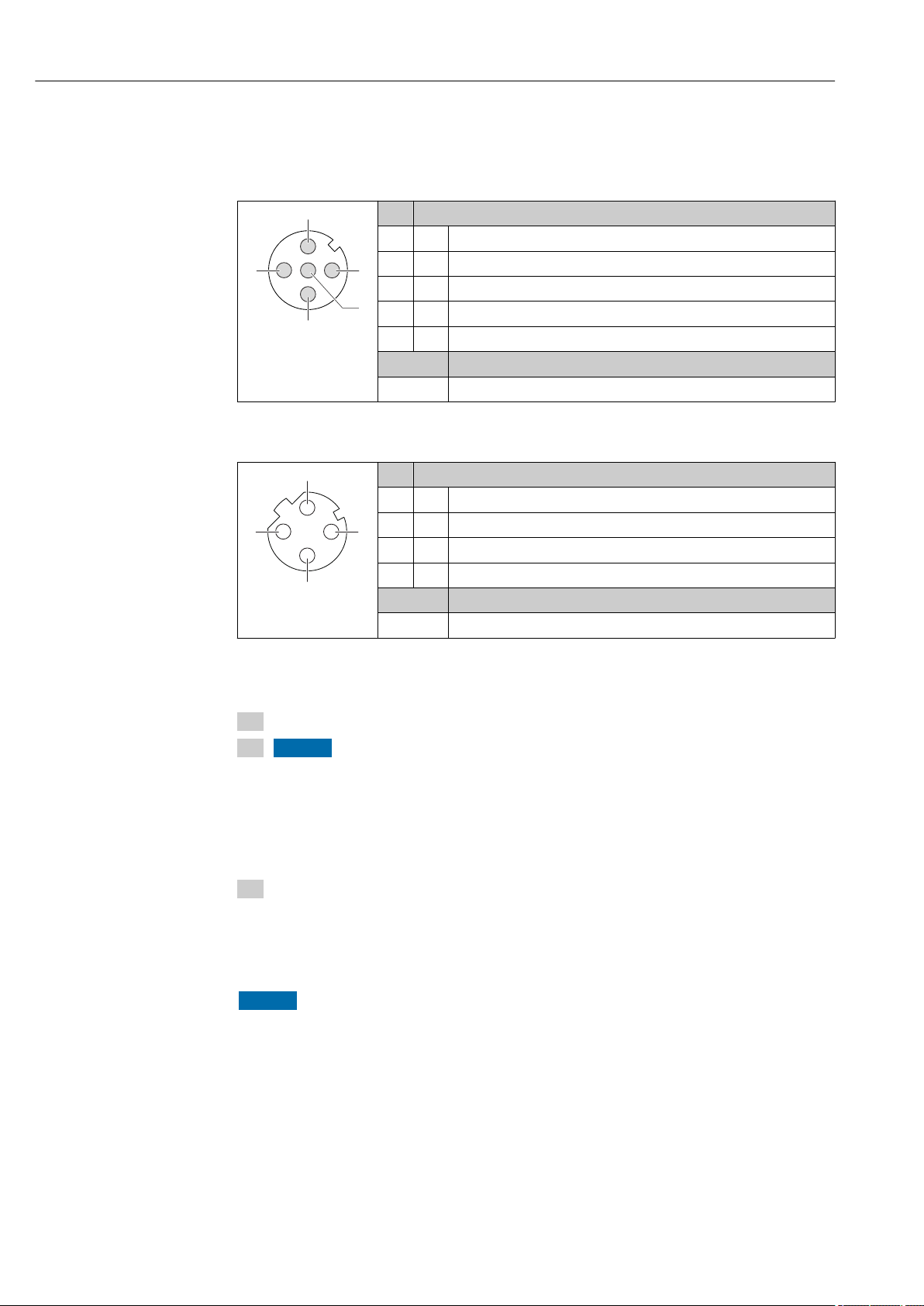
7.1.4 Pin assignment, device plug
Supply voltage
Pin Assignment
1 L+ DC 24 V
2 Not assigned
3 Not assigned
4 L- DC 24 V
A0016809
Device plug for signal transmission (device side)
A0016812
5 Grounding/shielding
Coding Plug/socket
A Plug
Pin Assignment
1 + TD +
2 + RD +
3 - TD –
4 - RD –
Coding Plug/socket
D Socket
7.1.5 Preparing the measuring device
1. Remove dummy plug if present.
2. NOTICE
Insufficient sealing of the housing!
Operational reliability of the measuring device could be compromised.
Use suitable cable glands corresponding to the degree of protection.
‣
If measuring device is delivered without cable glands:
Provide suitable cable gland for corresponding connecting cable .
3. If measuring device is delivered with cable glands:
Observe cable specification .
7.2 Connecting the measuring device
NOTICE
Limitation of electrical safety due to incorrect connection!
Have electrical connection work carried out by correspondingly trained specialists only.
‣
Observe applicable federal/national installation codes and regulations.
‣
Comply with local workplace safety regulations.
‣
For use in potentially explosive atmospheres, observe the information in the device-
‣
specific Ex documentation.
30 Endress+Hauser