

Endress+Hauser RSG35 Specifications
TI01079R/09/EN/05.18
71400825
2018-06-29
Products
Solutions Services
Technical Information
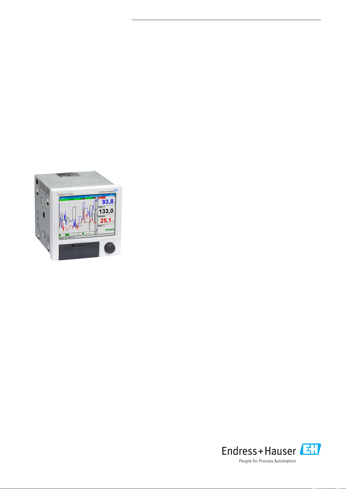
Ecograph T, RSG35
Universal Data Manager
Record, visualize and monitor
Application
The Ecograph T graphic display recorder records and visualizes relevant process
values via analog or digital input signals. The measured values are securely saved and
limit values are monitored. Furthermore the Ecograph T offers intuitive operation
and simple system integration. Remote configuration and visualization of the current
and recorded data is easy thanks to the integrated web server - no additional
software needs to be installed. In addition the Essential Version of the Field Data
Manager software is also supplied with the product as standard. This software can be
used to export the recorded data, save the data to an SQL database in a way that the
data cannot be manipulated, and visualize the data externally.
The Ecograph T is the right solution for a wide range of applications such as:
• Quality and quantity monitoring in the water and wastewater industry
• Monitoring of processes in power stations
• Displaying and recording of critical process parameters
• Tank and level monitoring
• Temperature monitoring in metal working
Your benefits
• Versatile: up to 12 universal inputs record a wide range of measuring signals
• Clear layout: 5.7" TFT screen for displaying measured values in a maximum of four
groups, with digital, bar graph and curve display
• Fast: 100 ms scan rate for all channels
• Compact: low installation depth, saves space and money
• Easy: intuitive operation via the navigator (jog/shuttle dial) on site, or userfriendly operation at the PC via the integrated web server
• Safe: reliable data archiving with internal memory and separate SD card
• Informative: e-mail notification in event of alarms and limit violation
• System-enabled: common interfaces such as Ethernet, RS232/485, USB and
optional slave function for Modbus RTU/TCP
• Smart: optional mathematics functions to calculate other values
• WebDAV: data saved on SD card transmitted directly to a PC via HTTP without any
additional software.

Function and system design
Ecograph T, RSG35
Measuring principle
Measuring system
Reliability Dependability
Electronic acquisition, display, recording, analysis, remote transmission and archiving of analog and
digital input signals.
The device is intended for installation in a panel or cabinet. There is also the option of operating it in
a desktop housing or field housing.
Multichannel data recording system with multicolored TFT display (145 mm / 5.7" screen size),
galvanically isolated universal inputs (U, I, TC, RTD, pulse, frequency), digital inputs, transmitter
power supply, limit relay, communication interfaces (USB, Ethernet, optional RS232/485), optionally
available with Modbus protocol, 128 MB internal memory, external SD card and USB stick. An
Essential Version of the Field Data Manager software is included for SQL-supported data analysis at
the PC.
The number of inputs available in the basic device can be individually increased using a
maximum of 3 plug-in cards. The device supplies power directly to connected two-wire
transmitters. The device is configured and operated via the navigator (jog/shuttle dial), via the
integrated web server and a PC, or via an external keyboard. Online help facilitates local
operation.
Depending on the device version, the MTBF is between 52 years and 24 years (calculated based on
SN29500 standard at 40°C)
Serviceability
Battery-backed time and data memory. It is advisable to have the backup battery replaced by a
service technician after 10 years.
Real time clock (RTC)
• Configurable summer/normal time changeover
• Battery buffer. It is advisable to have the backup battery replaced by a service technician after 10
years.
• Drift: <10 min./year
• Time synchronization possible via SNTP or via digital input.
Standard diagnostic functions as per Namur NE 107
The diagnostic code is made up of the error category as per Namur NE 107 and the message number.
• Cable open circuit, short-circuit
• Incorrect wiring
• Internal device errors
• Overrange/underrange detection
• Ambient temperature out-of-range detection
Device error/alarm relay
One relay can be used as an alarm relay. If the device detects a system error (e.g. hardware defect) or
a malfunction (e.g. cable open circuit), the selected output/relay switches.
This "alarm relay" switches if "F"-type errors occur (F = failure), i.e. "M"-type errors (M= Maintenance
required) do not switch the alarm relay.
Safety
The tamper-proof recorded data are saved and can be transferred to an external SQL database for
archiving in a way that prevents subsequent manipulation.
IT security
The manufacturer only provides a warranty if the device is installed and used as described in the
Operating Instructions. The device is equipped with security mechanisms to protect it against any
inadvertent changes to the device settings.
IT security measures in line with operators' security standards and designed to provide additional
protection for the device and device data transfer must be implemented by the operators themselves.
2 Endress+Hauser

Ecograph T, RSG35
Input
Measured values Number of analog universal inputs
Standard version without universal inputs. Optional input cards (slot 1-3) with 4 universal inputs
(4/8/12) each.
Number of digital inputs
6 digital inputs
Number of mathematics channels
4 mathematics channels (optional). Mathematics functions can be freely edited via a formula editor.
Integration of calculated values e.g. for totalization.
Number of limit values
30 limit values (individual channel assignment)
Function of analog universal inputs
You are free to choose between the following measured variables for each universal input: U, I, RTD,
TC, pulse input or frequency input.
Integration of input variable for totalization e.g. flow rate (m3/h) in quantity (m3).
Calculated values
The values of the universal inputs can be used to perform calculations in the mathematics channels.
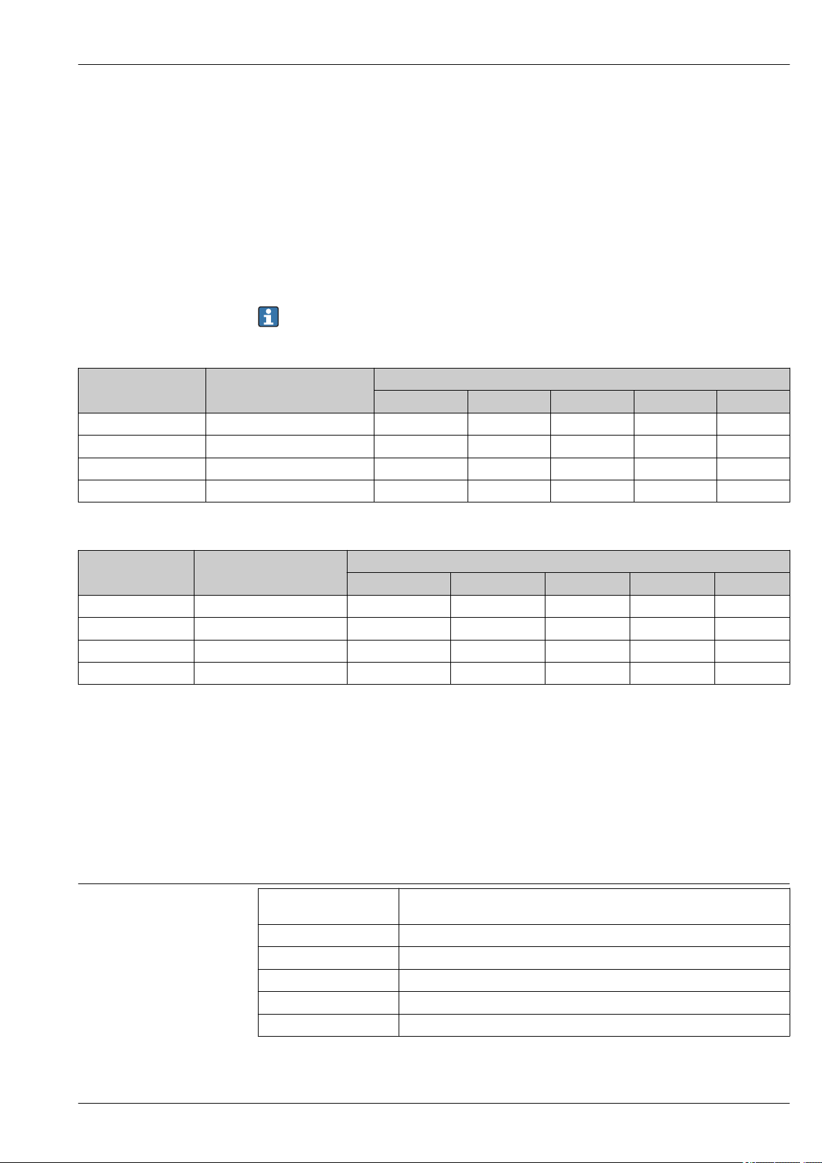
Measuring range of analog universal inputs
According to IEC 60873-1: An additional display error of ±1 digit is permitted for every measured
value.
User-definable measuring ranges per universal input of the multifunction card:
Measured
variable
Current (I) 0 to 20 mA; 0 to 20 mA quadratic
Voltage (U)
>1 V
Voltage (U)
≤1 V
Resistance
thermometer
(RTD)
Measuring range Maximum measured error of
0 to 5 mA
4 to 20 mA; 4 to 20 mA quadratic
±20 mA
Overrange: up to 22 mA or -22 mA
0 to 10 V; 0 to 10 V quadratic
0 to 5 V
1 to 5 V; 1 to 5 V quadratic
±10 V
±30 V
0 to 1 V; 0 to 1 V quadratic
±1 V
±150 mV
Pt100: -200 to 850 °C (-328 to 1562 °F) (IEC 60751:2008, α=0.00385)
Pt100: -200 to 510 °C (-328 to 950 °F) (JIS C 1604:1984, α=0.003916)
Pt100: -200 to 850 °C (-328 to 1562 °F) (GOST 6651-94, α=0.00391)
Pt500: -200 to 850 °C (-328 to 1562 °F) (IEC 60751:2008, α=0.00385)
Pt500: -200 to 510 °C (-328 to 950 °F) (JIS C 1604:1984, α=0.003916)
Pt1000: -200 to 600 °C (-328 to 1112 °F) (IEC 60751:2008, α=0.00385)
Pt1000: -200 to 510 °C (-328 to 950 °F) (JIS C 1604:1984, α=0.003916)
Cu50: -50 to 200 °C (-58 to 392 °F) (GOST 6651-94, α=4260)
Cu50: -200 to 200 °C (-328 to 392 °F) (GOST 6651-94, α=4280)
Pt50: -200 to 1100 °C (-328 to 2012 °F) (GOST 6651-94, α=0.00391)
Cu100: -200 to 200 °C (-328 to 392 °F) (GOST 6651-94, α=4280)
measuring range (oMR),
temperature drift
±0.1% oMR
Temperature drift: ±0.01%/K oMR
±0.1% oMR
Temperature drift: ±0.01%/K oMR
±0.1% oMR
Temperature drift: ±0.01%/K oMR
4-wire: ±0.1% oMR
3-wire: ±(0.1% oMR + 0.8 K)
2-wire: ±(0.1% oMR + 1.5 K)
Temperature drift: ±0.01%/K oMR
4-wire: ±0.2% oMR
3-wire: ±(0.2% oMR + 0.8 K)
2-wire: ±(0.2% oMR + 1.5 K)
Temperature drift: ±0.02%/K oMR
Input
resistance
Load: 50 Ω
±1 Ω
≥1 MΩ
≥2.5 MΩ
Endress+Hauser 3

Ecograph T, RSG35
Measured
variable
Thermocoupl
es (TC)
Pulse input
1)
(I)
Frequency
1)
input (I)
Measuring range Maximum measured error of
measuring range (oMR),
temperature drift
Pt46: -200 to 1100 °C (-328 to 2012 °F) (GOST 6651-94, α=0.00391)
Cu53: -200 to 200 °C (-328 to 392 °F) (GOST 6651-94, α=4280)
Type J (Fe-CuNi): -210 to 1200 °C (-346 to 2192 °F) (IEC 60584:2013)
Type K (NiCr-Ni): -270 to 1300 °C (-454 to 2372 °F) (IEC 60584:2013)
Type L (NiCr-CuNi): -200 to 800 °C (-328 to 1472 °F) (GOST R8.585:2001)
Type L (Fe-CuNi): -200 to 900 °C (-328 to 1652 °F) (DIN 43710-1985)
Type N (NiCrSi-NiSi): -270 to 1300 °C (-454 to 2372 °F) (IEC 60584:2013)
Type T (Cu-CuNi): -270 to 400 °C (-454 to 752 °F) (IEC 60584:2013)
Type A (W5Re-W20Re): 0 to 2500 °C (32 to 4532 °F) (ASTME 988-96)
Type B (Pt30Rh-Pt6Rh): 42 to 1820 °C (107.6 to 3308 °F) (IEC 60584:2013)
Type C (W5Re-W26Re): 0 to 2315 °C (32 to 4199 °F) (ASTME 988-96)
Type D (W3Re-W25Re): 0 to 2315 °C (32 to 4199 °F) (ASTME 988-96)
Type R (Pt13Rh-Pt): -50 to 1768 °C (-58 to 3214 °F) (IEC 60584:2013)
Type S (Pt10Rh-Pt): -50 to 1768 °C (-58 to 3214 °F) (IEC 60584:2013)
Min. Pulse length 40 μs, max. 12.5 kHz; 0 to 7 mA = LOW; 13 to 20 mA = HIGH Load: 50 Ω
0 to 10 kHz, overrange: up to 12.5 kHz; 0 to 7 mA = LOW; 13 to 20 mA = HIGH ±0.02% @ f <100 Hz of reading
4-wire: ±0.3% oMR
3-wire: ±(0.3% oMR + 0.8 K)
2-wire: ±(0.3% oMR + 1.5 K)
Temperature drift: ±0.02%/K oMR
±0.1% oMR from -100 °C (-148 °F)
±0.1% oMR from -130 °C (-202 °F)
±0.1% oMR from -100 °C (-148 °F)
±0.1% oMR from -100 °C (-148 °F)
±0.1% oMR from -100 °C (-148 °F)
±0.1% oMR from -200 °C (-328 °F)
Temperature drift: ±0.01%/K oMR
±0.15% oMR from 500 °C (932 °F)
±0.15% oMR from 600 °C (1112 °F)
±0.15% oMR from 500 °C (932 °F)
±0.15% oMR from 500 °C (932 °F)
±0.15% oMR from 100 °C (212 °F)
±0.15% oMR from 100 °C (212 °F)
Temperature drift: ±0.01%/K oMR
±0.01% @ f ≥100 Hz of reading
Temperature drift: 0.01% of
measured value over the entire
temperature range
Input
resistance
≥1 MΩ
≥1 MΩ
±1 Ω
1) If a universal input is used as a frequency or pulse input, a series resistor must be used in series connection with the voltage source. Example: 1.2
kΩ series resistor at 24 V
Maximum load of inputs
Limit values for input voltage and current as well as cable open circuit detection/line influence/temperature compensation:
Measured variable Limit values (steady-state, without
destroying input)
Current (I) Maximum permitted input voltage: 2.5 V
Maximum permitted input current: 50 mA
Pulse, frequency (I) Maximum permitted input voltage: 2.5 V
Maximum permitted input current: 50 mA
Voltage (U) >1 V Maximum permitted input voltage: 35 V 1 to 5 V range with disengageable cable open circuit monitoring:
Voltage (U) ≤1 V Maximum permitted input voltage: 24 V
Resistance
thermometer (RTD)
Thermocouples (TC) Maximum permitted input voltage: 24 V Influence of line resistance: <0.001%/Ω
Measuring current: ≤1 mA Maximum barrier resistance (or line resistance):
Cable open circuit detection/line influence/temperature compensation
4 to 20 mA range with disengageable cable open circuit monitoring to NAMUR
NE43. The following error ranges apply when NE43 is switched on:
≤3.8 mA: underrange
≥20.5 mA: overrange
≤ 3.6 mA or ≥ 21.0 mA: open circuit (display shows: – – – –)
No cable open circuit monitoring
<0.8 V or >5.2 V: cable open circuit (display shows: - - - -)
4-wire: max. 200 Ω; 3-wire: max. 40 Ω
Maximum influence of barrier resistance (or line resistance) for Pt100, Pt500
and Pt1000: 4-wire: 2 ppm/Ω, 3-wire: 20 ppm/Ω
Maximum influence of barrier resistance (or line resistance) for Pt46, Pt50,
Cu50, Cu53, Cu100 and Cu500: 4-wire: 6 ppm/Ω, 3-wire: 60 ppm/Ω
Cable open circuit monitoring if any connection is interrupted.
Error, internal temperature compensation: ≤ 2 K
Scan rate
Current/voltage/pulse/frequency input: 100 ms per channel
4 Endress+Hauser
Ecograph T, RSG35
Thermocouples and resistance temperature detector: 1 s per channel
Data storage/save cycle
Selectable save cycle. Choose from: 1s / 2s / 3s / 4s / 5s / 10s / 15s / 20s / 30s / 1min / 2min /
3min / 4min / 5min / 10min / 15min / 30min / 1h
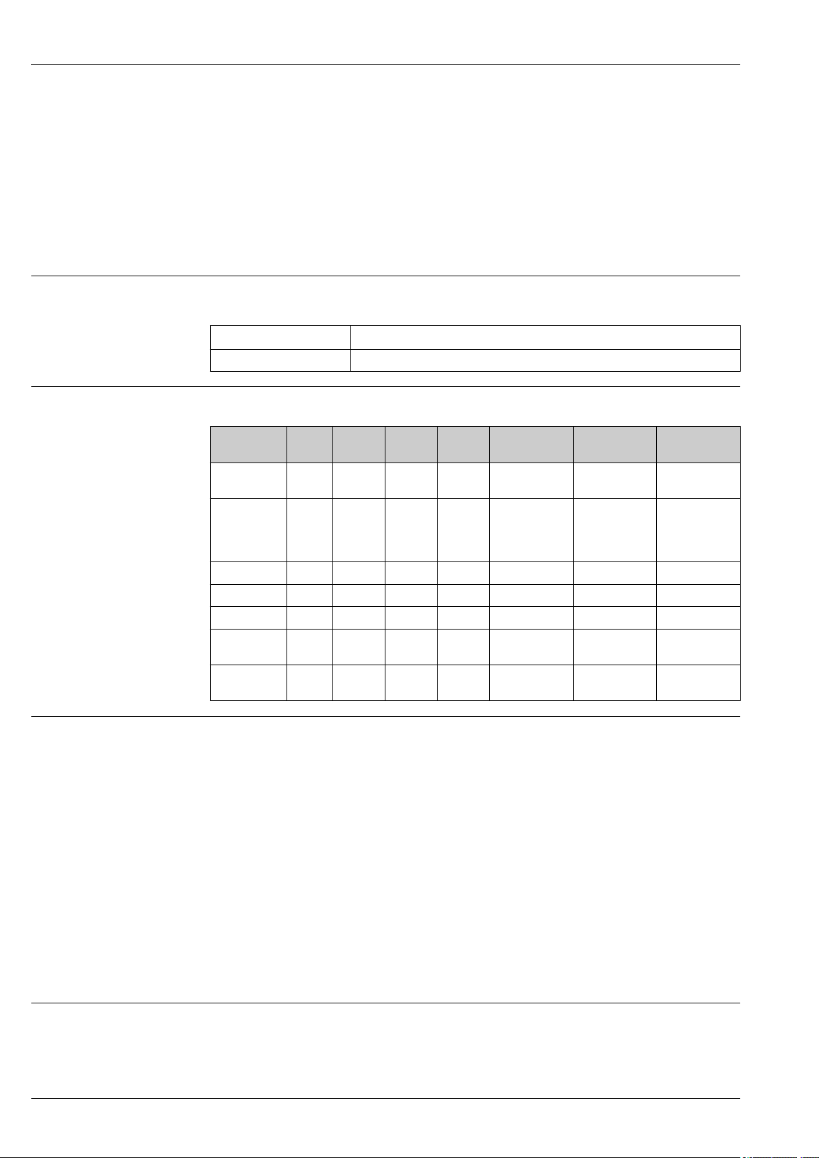
Typical recording duration
Prerequisites for following tables:
• No limit value violation / integration
• Digital input not used
• Signal analysis 1: off, 2: day, 3: month, 4: year
• No active mathematics channels
Frequent entries in the event log reduce the memory availability!
128 MB internal memory:
Analog inputs Channels in groups Storage cycle (weeks, days, hours)
5 min 1 min 30 s 10 s 1 s
1 1/0/0/0 668, 4, 14 135, 0, 5 67, 4, 4 22, 3, 20 2, 1, 18
4 4/0/0/0 491, 0, 10 99, 4, 17 49, 6, 12 16, 4, 15 1, 4, 16
8 4/4/0/0 246, 1, 14 49, 6, 1 24, 6, 19 8, 2, 7 0, 5, 20
12 4/4/4/0 164, 2, 4 33, 1, 18 16, 4, 13 5, 3, 21 0, 3, 21
External memory, 1 GB SD card:
Analog inputs Channels in groups Storage cycle (weeks, days, hours)
5 min 1 min 30 s 10 s 1 s
1 1/0/0/0 12825, 5, 20 2580, 4, 18 1291, 2, 5 430, 4, 14 43, 0, 12
4 4/0/0/0 8672, 5, 12 1749, 6, 13 875, 6, 13 292, 1, 8 29, 1, 14
8 4/4/0/0 4343, 1, 1 875, 1, 17 438, 0, 6 146, 0, 17 14, 4, 7
12 4/4/4/0 2896, 6, 13 583, 3, 21 292, 0, 6 97, 2, 20 9, 5, 4
Converter resolution
24 bit
Totalization
The interim, daily, monthly and yearly value and the total value can be determined (13-digit, 64 bit).
Analysis
Recording of quantity/operating time (standard function), also a min/max/median analysis within
the set time frame.
Digital inputs
Input level To IEC 61131-2: logical “0" (corresponds to -3 to +5 V), activation with logical "1"
(corresponds to +12 to +30 V)
Input frequency max. 25 Hz
Pulse length Min. 20 ms (pulse counter)
Pulse length Min. 100 ms (control input, messages, operating time)
Input current max. 2 mA
Input voltage Max. 30 V
Endress+Hauser 5
Ecograph T, RSG35
Selectable functions
• Functions of the digital input: control input, ON/OFF message, pulse counter (13-digit, 64 bit),
operating time, message+operating time, quantity from time, Modbus slave.
• Functions of the control input: start recording, screen saver on, lock setup, time synchronization,
limit monitoring on/off, lock keyboard/navigator, start/stop analysis.
Output
Auxiliary voltage output
Galvanic isolation
The auxiliary voltage output can be used for loop power supply or to control the digital inputs. The
auxiliary voltage is short-circuit proof and galvanically isolated.
Output voltage 24 VDC ±15%
Output current Max. 250 mA
All inputs and outputs are galvanically isolated from each other and designed for the following testing
voltages:
Relay DigitalinAnaloginEthernet RS232/RS485 USB Auxiliary
voltage output
Relay 500
V
Digital in 2 kVDCGalvanic
Analog in 2 kVDC500 VDC500 VDC500 VDC500 V
Ethernet 2 kVDC500 VDC500 VDC- 500 V
RS232/RS485 2 kVDC500 VDC500 VDC500 VDC- 500 V
USB 2 kVDC500 VDC500 VDC500 VDC500 V
Auxiliary
2 kVDC500 VDC500 VDC500 VDC500 V
voltage output
2 kV
DC
2 kV
DC
2 kV
DC
500 VDC500 VDC500 V
2 kV
DC
DC
DC
2 kV
500 V
DC
DC
2 kV
500 V
DC
DC
ally
connecte
d
DC
DC
DC
500 V
DC
500 V
DC
DC
Galvanically
500 V
500 V
500 V
500 V
DC
DC
DC
DC
connected
DC
500 V
DC
-
Relay outputs
A mix of low voltage (230 V) and safety extra low voltage (SELV circuits) is not permitted at the
connections of the relay contacts.
Alarm relay
1 alarm relay with changeover contact.
Standard relay
5 relays with NO contact, e.g. for limit value messages (can be configured as NC contact).
Relay switching capacity
• Max. switching capacity: 3 A @ 30 V DC
• Max. switching capacity: 3 A @ 250 V AC
• Min. switching load: 300 mW
Switching cycles
5
>10
Cable specification Cable specification, spring terminals
All connections on the rear of the device are designed as pluggable screw or spring terminal blocks
with reverse polarity protection. This makes the connection very quick and easy. The spring
terminals are unlocked with a slotted screwdriver (size 0).
6 Endress+Hauser
 Loading...