

Page 1

RID 261
PROFIBUS-PA
Betriebsanleitung
Operating instructions
Mise en service
Manuale operativo
BA 098R/09/c4/08.00
No.: 510 01238
Page 2

RID 261 PROFIBUS-PA
Endress+Hauser
Page 3

PROFIBUS-PA Display
Betriebsanleitung
(Bitte lesen, bevor Sie das Gerät in Betrieb nehmen)
Gerätenummer:...........................
PROFIBUS-PA Display
Operating instructions
(Please read before installing the unit)
Unit number:................................
PROFIBUS-PA Display
Mise en service
(A lire avant de mettre l’appareil en service)
N° d’appareil:....................................
PROFIBUS-PA Display
Manuale operativo
(Leggere prima di installare l’unità)
Numero unità:....................................
Deutsch
1 ... 20
Français
41...60
English
21... 40
Italiano
61...80
PROFIBUS-PA Display
1
Page 4

Inhaltsverzeichnis Seite
1. Sicherheitshinweise 3
1.1 Bestimmungsgemäße Verwendung 3
1.2 Montage, Inbetriebnahme, Bedienung 3
1.3 Betriebssicherheit 4
1.4 Rücksendung 4
1.5 Sicherheitszeichen und Symbole 4
2. Identifizierung 4
2.1 Gerätebezeichnung 4
2.2 Lieferumfang 4
3. Arbeitsweise und Systemaufbau 5
3.1 Funktionsweise 5
3.2 Systemaufbau 5
4. Montage 5
4.1 Einbaubedingungen und Einbau 5
5. Verdrahtung 7
5.1 Klemmenplan 7
6. Inbetriebnahme und Bedienung 8
6.1 Installationskontrolle 8
6.2 Anzeige- und Bedienelemente 8
6.3 Inbetriebnahme 11
7. Störungsbehebung 12
7.1 Fehlermeldungen 12
7.2 Fehleranalyse 12
8. Wartung 13
8.1 Instandhaltung 13
8.2 Reparatur, Entsorgung 13
9. Zubehör 14
10. Technische Daten 15
11. Anhang 19
11.1Einstellung des Gerätes 19
11.2Grenzwertverletzungen 19
Anlagendokumentation
Deutsch
Inhaltsverzeichnis
2
Page 5

1. Sicherheitshinweise
1.1 Bestimmungsgemässe Verwendung
- Der PROFIBUS-PA Anzeiger hat das Werk in
sicherheitstechnisch einwandfreiem Zustand
verlassen.
- Ein gefahrloser Betrieb ist nur sichergestellt, wenn
die Betriebsanleitung beachtet wird.
- Für Schäden aus unsachgemässem oder nicht
bestimmungsgemässem Gebrauch haftet der
Hersteller nicht.
- Gerät nur in dem dafür vorgesehenen
Temperaturbereich betreiben.
- Messsysteme, die im explosionsgefährdetem
Bereich eingesetzt werden, liegt eine separate
Ex-Dokumentation bei, die ein fester Bestandteil
dieser Betriebsanleitung ist. Die darin aufgeführten
Installationsvorschriften und Anschlusswerte müssen
ebenfalls konsequent beachtet werden!
1.2 Montage, Inbetriebnahme,
Bedienung
Das Gerät ist nach dem Stand der Technik betriebssicher
gebaut und berücksichtigt die einschlägigen Vorschriften und
EU-Richtlinien. Wenn es jedoch unsachgemäss oder nicht
bestimmungsgemäss eingesetzt wird, können von ihm
applikationsbedingte Gefahren ausgehen.
Montage, elektrische Installation, Inbetriebnahme und Wartung
des Gerätes dürfen nur durch ausgebildetes Fachpersonal
erfolgen, das vom Anlagenbetreiber dazu autorisiert wurde.
Das Fachpersonal muss diese Betriebsanleitung unbedingt
gelesen und verstanden haben und deren Anweisungen
unbedingt befolgen. Der Installateur hat dafür Sorge zu tragen,
dass das Messsystem gemäss den elektrischen
Anschlussplänen korrekt angeschlossen ist.
Veränderungen und Reparaturen am Gerät dürfen nur
vorgenommen werden, wenn dies die Betriebsanleitung
ausdrücklich zulässt. Beachten Sie grundsätzlich die in Ihrem
Land geltenden Vorschriften bezüglich Öffnen und Reparieren
von elektrischen Geräten.
Deutsch
1. Sicherheitshinweise
3
Page 6

1.3 Betriebssicherheit
Explosionsgefährdeter Bereich
Bei Einsatz des Messsystems in explosionsgefährdeten
Bereichen sind die entsprechenden nationalen Normen
einzuhalten. Stellen Sie sicher, dass das Fachpersonal
ausreichend ausgebildet ist. Die messtechnischen und
sicherheitstechnischen Auflagen an die Messstellen sind
einzuhalten.
Technischer Fortschritt
Der Hersteller behält sich vor, technische Daten ohne spezielle
Ankündigung dem entwicklungstechnischen Fortschritt
anzupassen. Über die Aktualität und eventuelle Erweiterungen
dieser Betriebsanleitung erhalten Sie bei Ihrer Vertriebsstelle
Auskunft.
1.4 Rücksendung
Bei Rücksendung des Gerätes zur Reparatur legen Sie bitte
eine Notiz mit der Beschreibung des Fehlers und der
Anwendung bei.
Bei Transportschäden informieren Sie bitte den Spediteur und
den Lieferanten.
1.5 Sicherheitszeichen und Symbole
Bitte beachten Sie folgende Zeichen:
Hinweis: Ratschläge zur besseren Inbetriebnahme
Achtung: Nichtbeachtung kann zum Defekt des
Gerätes oder zu Fehlfunktionen führen!
2. Identifizierung
2.1 Gerätebezeichnung
Das richtige Gerät?
Vergleichen Sie bitte den Bestellcode auf dem Typenschild
(am Gerät) mit dem auf dem Lieferschein.
2.2 Lieferumfang
- PROFIBUS-PA Anzeiger, Ausführung nach Bestellung.
- Betriebsanleitung
- Zubehör laut Bestellung
2. Identifizierung
4
Page 7

3. Arbeitsweise und Systemaufbau
3.1 Funktionsweise
Anzeige von Prozessinformationen (z.B. Messwert und
Grenzwertverletzung), der am PROFIBUS-PA-Netzwerk
angeschlossenen Feldbusteilnehmer (z.B. Sensoren oder
Aktoren). Der Prozesswert wird als 7stellige Zahl
angezeigt, der Prozesswertstatus über Grenzwertmarken.
3.2 Systemaufbau
Microcontroller gesteuerter Vorortanzeiger mit
PROFIBUS-PA-Schnittstelleund LC-Anzeige. Die
Aktualisierung der Anzeige erfolgt sekündlich.
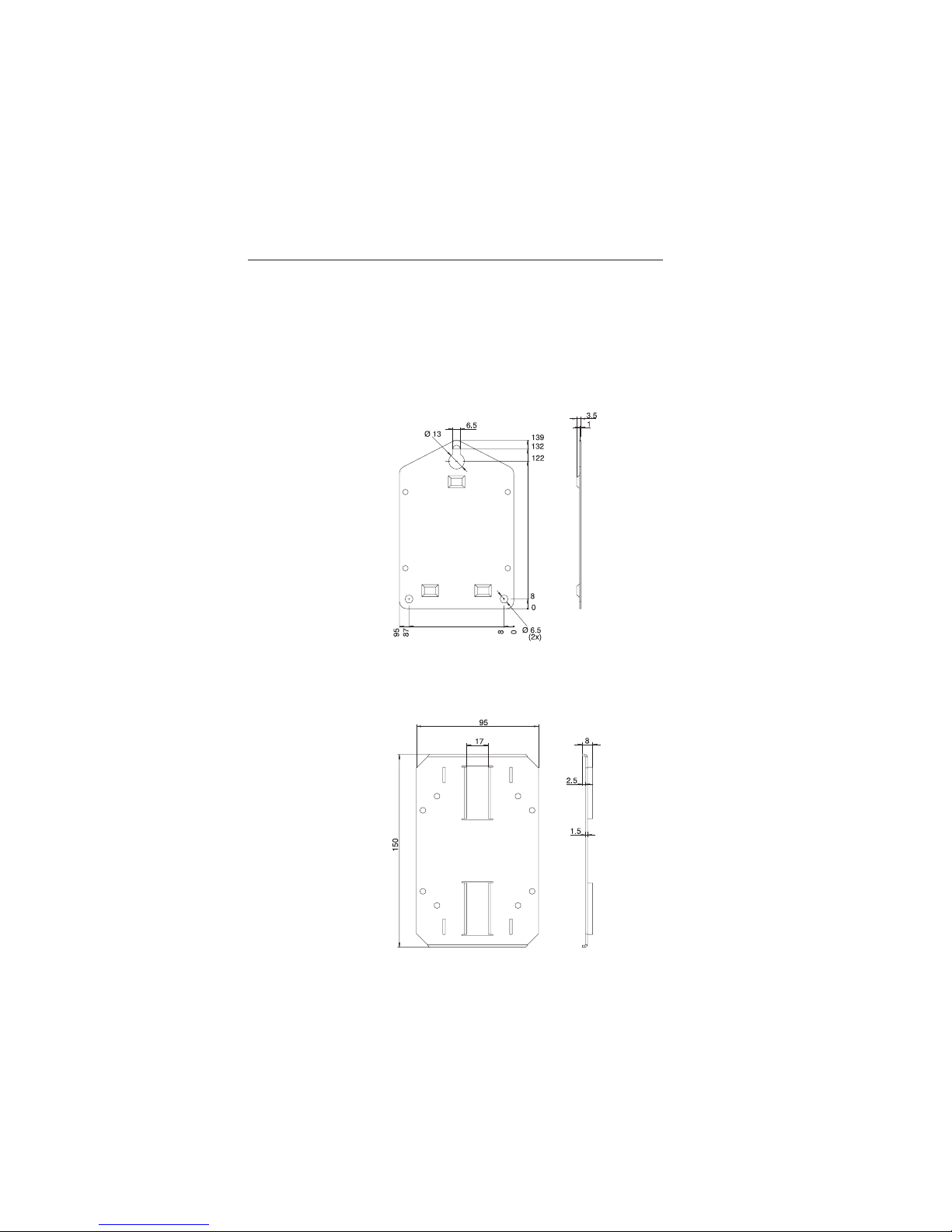
4. Montage
4.1 Einbaubedingungen und Einbau
Einbaumaße (in mm)
Das Gerät ist für die Wand-, und Rohrmontage geeignet.
Hierzu kann optional ein Wand-, bzw. Rohrhalter bestellt
werden. (Siehe 9. Zubehör)
3. Arbeitsweise und Systemaufbau
5
Page 8

Wandmontage
Öffnen Sie den Gehäusedeckel und montieren Sie das Gerät (siehe Skizze).
Rohrmontage
Öffnen Sie den Gehäusedeckel und montieren Sie das Gerät (siehe Skizze).
4. Montage
6
Page 9

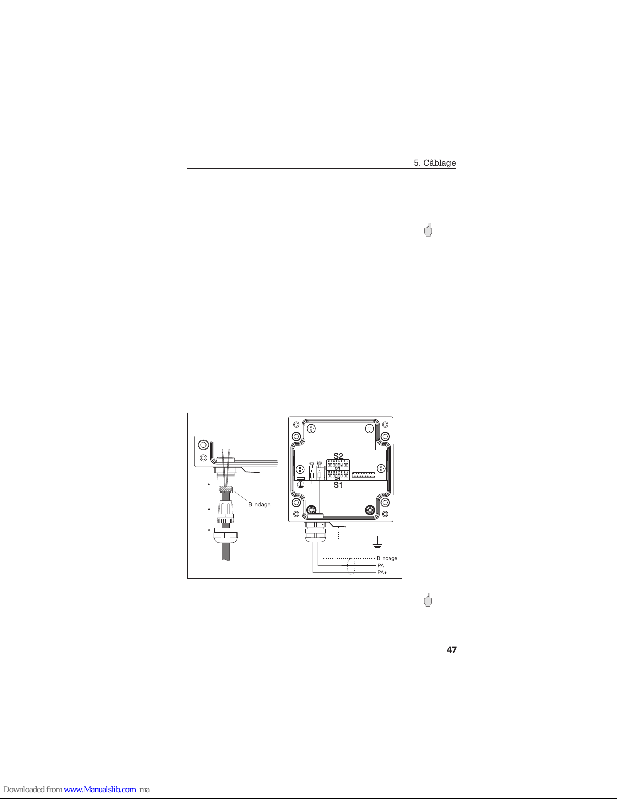
5. Verdrahtung
Achtung: Beachten Sie für den Anschluss von Geräten für den
explosionsgefährdeten Bereich die entsprechenden Hinweise
und Anschlussbilder in den Ex-spezifischen Zusatzdokumentationen zu dieser Betriebsanleitung.
Schutzart
Die Geräte erfüllen alle Anforderungen gemäss IP 66. Um nach
erfolgter Montage oder nach einem Service-Fall diese zu
gewährleisten, müssen folgende Punkte zwingend beachtet
werden:
- Die Gehäusedichtungen müssen sauber und unbeschädigt in
die Dichtungsnut eingelegt sein. Gegebenenfalls sind die
Dichtungen zu reinigen, zu trocknen oder zu ersetzen.
- Sämtliche Gehäuseschrauben und die Kabeldurchführung
müssen fest angezogen sein.
5.1 Klemmenplan
Die Anschlussklemmen für die PROFIBUS-PA Leitungen
befinden sich unter der Schraubabdeckungan der linken Seite
des Gerätes. Öffnen Sie die PG-Verschraubungund schliessen
Sie die PROFIBUS-PA Leitung gemäss Skizze an.
Achtung: Sorgen Sie so für eine leitfähige Verbindung des
Schirmes mit der metallischen PG-Verschraubung. Erden Sie
das Gerät über die Erdungslasche. Nur so ist eine
ausreichende Störfestigkeit gewährleistet.
aaaaaaa
aaaaaaa
a
aaaaaaaa
bbbbbbb
bbbbbbb
b
bbbbbbbb
5. Verdrahtung
7
Page 10

6. Inbetriebnahme und Bedienung
6.1 Installationskontrolle
Vor dem ersten Anklemmen des Anzeigers sollten Sie nochmals folgende
Kontrollen durchführen:
Überprüfen Sie die elektrischen Anschlüsse und Klemmenbelegungen.
Machen Sie sich bereits vor dem ersten Anklemmen mit der Bedienung des
Anzeigers vertraut.
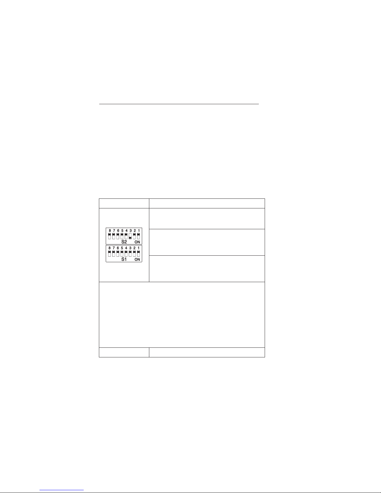
6.2 Anzeige- und Bedienelemente
Bedienelemente
DIP-Schalter Beschreibung
S2/8:
off=Eingangsdaten, on=Ausgangsdaten,
Werkseinstellung: Eingangsdaten
S2/1-7:
Binär kodiert
Busadresse [0...126],
Werkseinstellung: Busadresse 4 (S2/3 = on)
S1/1-8:
Binär kodiert
Offset in Byte [0...244],
Werkseinstellung: kein Offset
Die 7 niederwertigen Pins (PIN1 bis PIN7) des Adress-DIP-Schalters (S2)
spezifizieren die Feldbusadresse des Teilnehmers, dessen Prozesswert
erfasst werden sollen. Der Wertebereich beträgt beim PROFIBUS-PA 0...125.
PIN8 des Adress-DIP-Schalters (S2) legt fest, ob die Ausgangsdaten
(PIN8=1, z.B. Steuerung Aktor) oder die Eingangsdaten (PIN8=0, z.B.
Prozesswert Sensor) erfasst werden sollen.
Über die 8 Pins des Offset-DIP-Schalters (S1) erfolgt die Offseteinstellung.
Der Offset gibt die Stelle im Datentelegramm (bei Sensoren mit einem
Prozesswert = 0, z.B. Temperatursensor) an, an der der anzuzeigende
Prozesswert (4 Byte Prozesswert, 1 Byte Status) beginnt. Der Wertebereich
beträgt beim PROFIBUS-PA 0...245 Byte.
Werkseinstellung 1. Prozesswert des Sensors an der Adresse 4
6. Inbetriebnahme und Bedienung
8
Page 11

Wertigkeitstabelle:
S 12345678
Wertigkeit 1 2 4 8 16 32 64 128
Beispiel:
Adresse 6 entspricht einer Wertigkeit 2+4, daraus folgt:
S2/2 ⇒ ON
S2/3 ⇒ ON (siehe Abbildung)
Hinweis: Änderung der DIP-Schaltereinstellung wird nach
wenigen Sekunden aktiv (kein Reset erforderlich).
In Kapitel 11.1 finden Sie die Einstellung der DIP-Schalter für
die Anzeige des Volumenfluss eines Durchflussmessgerätes an
der Adresse 68.
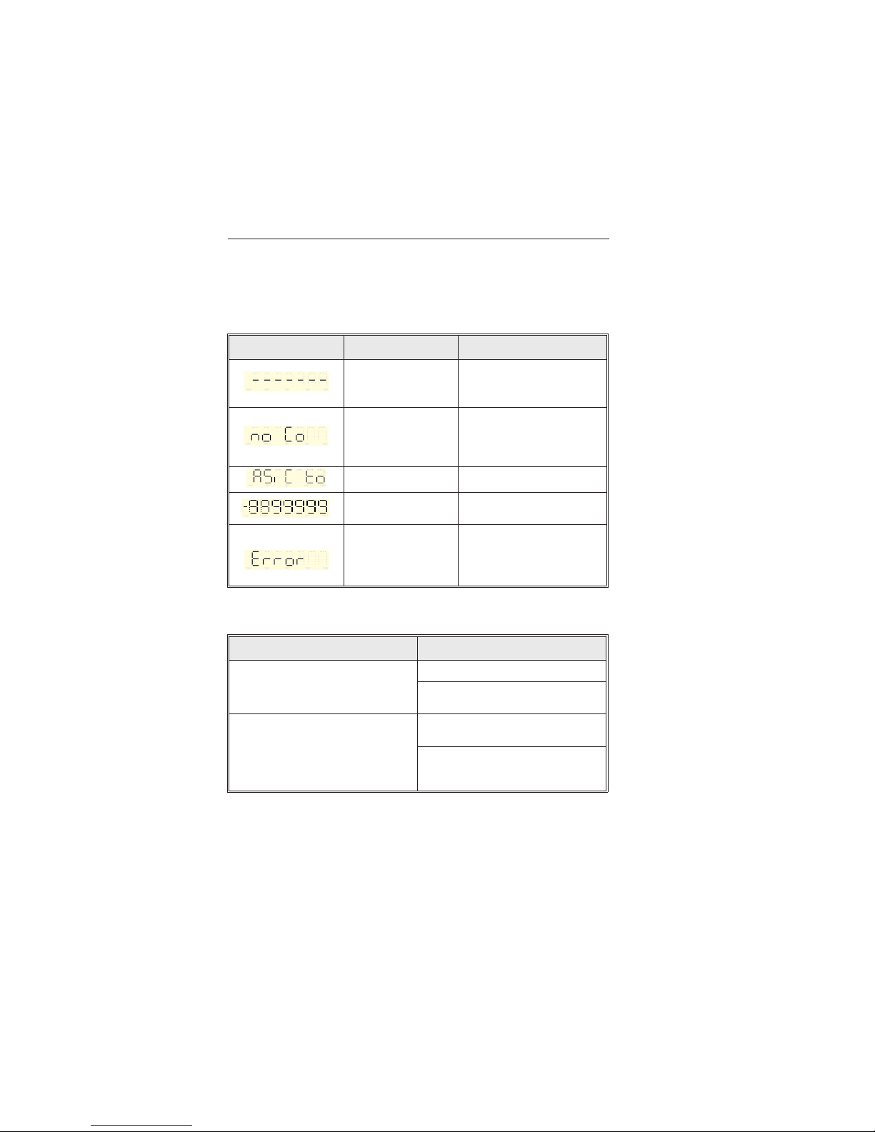
Anzeigelemente LC-Display
Anzeige
7-stellige LC-Anzeige,
Ziffernhöhe 7,5 mm
Der Profibus-PA Anzeiger liefert neben dem Prozesswert
folgende Informationen:
Anzeige Beschreibung
Start:
Anzeige nach Reset
Prozesswert: Zahl (evtl. mit
negativem Vorzeichen) mit maximal
3 Nachkommastellen und OK-Marke
bei Prozesswertstatus OK
Prozesswert mit
Grenzwertmarken:
Prozesswertstatus OK oder
UNCERTAIN Grenzwertverletzung
[1]
[1] Grenzwertverletzungab PROFIBUS-PAProfil V3.0 (siehe auch Kap. 11.2)
6. Inbetriebnahme und Bedienung
9
Page 12

Anzeige Beschreibung
Error: Prozesswertstatus enthält Status BAD, einen
nicht definierten Wert oder keinen gültigen
Prozesswert
kein Prozesswert:
Prozesswertübertragung ist gestört, kein gültiger
Prozesswert
no Co:
10 s kein gültiger Prozesswert
Status
(hex)
Meldung Bedeutung
40...7f
Wert
Status UNCERTAIN
80
Wert
Status OK
89
Wert OK mit active advisory
alarm, low limit
[1]
8d
Wert OK mit active critical
alarm, low limit
[1]
8a
Wert OK mit active advisory
alarm, high limit
[1]
8e
Wert OK mit active critical
alarm, high limit
[1]
00...3F
Wert Status BAD
[1] Grenzwertmeldungenab PROFIBUS-PA Profil V3.0(siehe auch Kap. 11.2)
6. Inbetriebnahme und Bedienung
10
Page 13

Beschriftungsfelder
Die Frontfolie besitzt drei Beschriftungsfelder.
Beschriftung der einzelnen Felder:
Entfetten und reinigen Sie die Frontfolie (z.B. mit Spiritus).
Beschriften Sie die Felder mit einem lichtbeständigen,
wasserfesten Folienschreiber.
6.3 Inbetriebnahme
Nach dem Anschluss und den Einstellungen kann das Gerät in
Betrieb genommen werden. Bitte beachten Sie hierbei die
Funktion des Displays.
Ê = Beschriftungsfeld für
physikalische Einheit
Ë = Beschriftungsfelder
Anzeigebereich
Wertebereich Anzeige Anmerkung
0...9.999,999
1234,567
10.000...99.999,99 12345,67
100.000...999.999,99 123456,7
1.000.000...9.999.999 1234567
> 9.999.999 9999999
blinkend mit
1Hz
Aktualisierung < 1 / s
6. Inbetriebnahme und Bedienung
11
Page 14

7. Störungsbehebung
7.1 Fehlermeldungen
Meldung Bedeutung Fehlerbehebung
Prozesswertübertragung ist
gestört, Prozesswert ist
unvollständig.
Überprüfen Sie die Offseteinstellung
des PROFIBUS-PAAnzeigers und die
Konfiguration des ausgewählten
Busteilnehmers. (6.2)
10 s kein gültiger
Prozesswert,
kein Slavemit dieser
Adresse
Passen Siedie Adresse des
PROFIBUS-PA Anzeigers an die
Adresse desausgewählten
Busteilnehmers an (6.2). Überprüfen
Sie dieOffseteinstellung des
PROFIBUS-PA Anzeigers.
Gerät defekt
Austausch desGerätes erforderlich
Prozesswert istzu gross,
oder falscherOffset
eingestellt.
Überprüfen Sie die Konfigurationdes
ausgewählten Busteilnehmers und die
Offseteinstellungdes PROFIBUS-PA
Anzeigers. (6.2)
Prozesswertstatus enthält
nicht definiertenWert,
keinen gültigen
Prozesswert oderStatus
BAD
Überprüfen Sie die Offseteinstellung
des PROFIBUS-PAAnzeigers. Bei
Übertragung der Daten vom Master
zum Busteilnehmerstellen Sie sicher,
dass derProzesswertstatus definierte
Werte enthält(6.2).
7.2 Fehleranalyse
blinkend
Fehler Fehlerbehebung
Keine Anzeige auf dem Display
Versorgung vomBus überprüfen
Gerät defekt (CPUoder Klemmenplatine),
schicken Sie dasGerät an den Hersteller
zurück.
Prozesswert des
Busteilnehmers/Anzeigers nicht
Identisch
Überprüfen Siedie Offseteinstellung des
PROFIBUS-PA Anzeigers.
Passen Sie dieAdresse des
PROFIBUS-PA Anzeigersan die Adresse
des ausgewähltenBusteilnehmers an.
7. Störungsbehebung
12
Page 15

8. Wartung
8.1 Instandhaltung
Für den PROFIBUS-PA Anzeiger sind keine speziellen
Instandhaltungs- und Wartungsarbeiten erforderlich.
8.2 Reparatur
Für eine spätere Wiederverwendung oder einen
Reparaturfall ist das Gerät geschützt zu verpacken.
Optimalen Schutz bietet die Originalverpackung.
Reparaturen dürfen nur durch Fachpersonal
durchgeführt werden. Bei Einsendung zur Reparatur
legen Sie bitte dem Gerät eine Notiz mit der
Beschreibung des Fehlers und der Anwendung bei.
Warnung: Bei Ex-Geräten kann keine Fehlerdiagnose
am offenen Gerät durchgeführt werden. Dadurch wird
die Zündschutzart aufgehoben.
Entsorgung:
Für eine spätere Entsorgung beachten Sie bitte die
örtlichen Vorschriften.
8. Wartung
13
Page 16

9. Zubehör
(Für Bestellungen sprechen Sie bitte Ihren Lieferanten an)
Montagehalter zur Wandmontage
Halteplatte aus V2A 1 mm Stärke Best. Nr. 510 00946
Montagehalter zur Rohrmontage
Halteplatte aus V2A 1,5 mm Stärke Best. Nr. 510 00924
9. Zubehör
14
Page 17

10.Technische Daten
Funktionsprinzip Anzeige von Prozessinformationen (z.B. Messwert
und Grenzwertverletzung), der am PROFIBUS-PANetzwerk angeschlossenen Feldbusteilnehmer (z.B.
Sensoren oder Aktoren). Der Prozesswert wird als
7-stellige Zahl angezeigt, der Prozesswertstatus über
Grenzwertmarken.
Systemaufbau Microcontroller gesteuerter Vorortanzeiger mit
PROFIBUS-PA- Schnittstelle und LC-Anzeige
Blockdiagramm
Protokoll PROFIBUS-PA gemäss EN 50170 Volume 2,
Übertragungstechnik gemäss IEC 1158-2
Daten 5 Byte, Eingangs- oder Ausgangsdaten
(Prozesswert und Grenzwertanzeige)
10. Technische Daten
15
Page 18

Prozesswert 4 Byte, 32-Bit Gleitpunktzahl (IEEE-754)
Grenzwertanzeige 1 Byte, Status PROFIBUS-PA Profile V3.0
PA-Funktion Listener
Übertragungsrate
PROFIBUS-PA 31,25 kBit/s
Physikalische Schicht IEC 1158-2
Spannungsversorgung
und Anschluss
siehe Kapitel 5.1
Hilfsenergie Speisung über PROFIBUS-PA non-EEx: 9...32 V
DC
Speisung über PROFIBUS-PA EEx: 9...15 V
DC
Leistungsaufnahme < 1 W
DC
Stromaufnahme 10 mA ± 1 mA
Achtung: Die Stromaufnahme von
max. 11 mA des PROFIBUS-PAAnzeigers
muss bei der Planung des PROFIBUS-PANetzwerkes berücksichtigt werden!
Einbaubedingungen
Einbaulage keine Einschränkungen
Umgebungsbedingungen
Umgebungstemperatur
-25...+60 °C (für EEx-Bereich siehe Ex-Schutz)
Lagertemperatur -25...+70 °C
Klimaklasse nachEN 60 654-1, Klasse C1
Schutzart IP 66
Schwingungsfestigkeit IEC 60 654-3, v<3 mm/s, 1<f<150 Hz
10. Technische Daten
16
Page 19

Elektromagnetische Verträglichkeit
EMV Störfestigkeit und Störaussendung nach EN 61 326-1
Bauform/Masse 100 x 100 x 61 mm; siehe Kapitel 4.1
Gewicht ca. 0,6 kg
Werkstoffe Gehäuse Aluminiumdruckguss, Oberfläche
Pulverbeschichtet
Wand-/ Rohrmontagehalter: 1.4301
Spannband: 1.4301
Anschlussklemmen
(Schraubklemmen) ≤ 2,5 mm²
Kabeleinführung Buskabel:
Kabelverschraubung PG 13,5
(für 5...9 mm Kabeldurchmesser) oder
Kabeldurchführung NPT 1/2 “ oder
Feldbus Gerätestecker (WDM) 150 mm
Bedienelemente
DIP-Schalter siehe Kapitel 6.2
Werkseinstellung 1. Prozesswert des Sensors an der Adresse 4
Anzeigeelemente LC-Display
Anzeige 7-stellige LC-Anzeige,
Ziffernhöhe 7,5 mm; siehe Kapitel 6.2
Anzeigebereich siehe Kapitel 6.2
Prozesswertstatus siehe Kapitel 6.2
Aktualisierung < 1 / s
10. Technische Daten
17
Page 20

CE-Kennzeichnung Das Gerät erfüllt die gesetzlichen Anforderungen aus
den EU-Richtlinien
Zertifikationsnummer DMT 99 ATEX 062
Max. Umgebungs-
temperatur T5 = +60 °C
Höchstwerte im Fehlerfall
Eingangsspannung 15 V
Kurzschlussstrom 31 mA
Kapazität C
i
≅ 0µF
Induktivität L
i ≤
2µH
10. Technische Daten
18
Page 21

11. Anhang
11.1 Beispiel für Einstellung des
PROFIBUS-PA Anzeigers
Anzeige des Summenzählers 1 eines
Durchflussmessgerätes mit der Busadresse 68.
Das Durchflussmessgerät kann ein Datentelegramm mit der
Länge 55 Byte senden. Vor dem Summenzähler 1 wird der
Massefluss (5 Byte) übertragen.
Der Offset wird am Schalter S1 auf 5 eingestellt.
Der Summenzähler ist ein Prozesswert des Sensors
(Eingangsdaten),
d. h. S2/8= off.
Am Schalter S2 wird die Busadresse des PROFIBUS-PAGerätes (Durchflussmessgerät), in diesem Beispiel 68,
eingestellt.
11.2 Grenzwertverletzungen PROFIBUS-PA Profile V3.0
Prozesswert
11. Anhang
19
Page 22

Notizen
20
Page 23

PROFIBUS-PA Display
Betriebsanleitung
(Bitte lesen, bevor Sie das Gerät in Betrieb nehmen)
Gerätenummer:...........................
PROFIBUS-PA Display
Operating instructions
(Please read before installing the unit)
Unit number:................................
PROFIBUS-PA Display
Mise en service
(A lire avant de mettre l’appareil en service)
N° d’appareil:....................................
PROFIBUS-PA Display
Manuale operativo
(Leggere prima di installare l’unità)
Numero unità:....................................
Deutsch
1 ... 20
Français
41...60
English
21... 40
Italiano
61...80
PROFIBUS-PA Display
21
Page 24

Contents Page
1.Safetynotes 23
1.1Correctuse 23
1.2Installation,settingup,operation 23
1.3Operationalsafety 24
1.4Returns 24
1.5Safetysignsandsymbols 24
2.Identification 24
2.1Unitidentification 24
2.2Whatisdelivered 24
3.Operationandsystemconstruction 25
3.1Operation 25
3.2System 25
4.Installation 25
4.1Installationconditions 25
5.Electricalconnection 27
5.1Terminallayout 27
6.Settingupandoperation 28
6.1Installationcontrol 28
6.2Displayandoperatingelements 28
6.3Settingup 31
7.Faultfinding 32
7.1Faultmessages 32
7.2Faultanalysis 32
8.Maintenance 33
8.1Generalmaintenance 33
8.2 Repairs,disposal 33
9.Accessories 34
10.Technicaldata 35
11.Appendix 39
11.1Devicesettings 39
11.2Alarmsetpointcondition 39
Plantdocumentation
English
Contents
22
Page 25

1. Safety notes
1.1 Correct use
- The PROFIBUS-PA display leaves the factory in
perfect and safe condition.
- Safe operation can only be guaranteed if the
contents of the operating manual are followed.
- The manufacturer does not take responsibility for any
damage caused by incorrect use of the unit.
- The unit must only be used within the temperature
range specified.
- For measurement systems in hazardous areas there
is a separate Ex-operating manual. The contents are
a fixed part of this document. All installation
requirements and connection values must be taken
into consideration when installing the unit!
1.2 Installation, initial setting up,
operation
The unit has been constructed using the most up to date safety
technology and includes takes EU-recommendations into
consideration. However if it is installed incorrectly or not in line
with regulations then it could become dangerous. Mechanical
and electrical installation, setting up and maintenance of the
unit must only be carried out by skilled and qualified personnel
who have been authorised to do so by the plant operator. The
skilled personnel must have read and understood these
installation and operating instructions. They must follow them
carefully. The installer must make sure that that the unit is
correctly connected by following the electrical connection
diagrams. Changes and repairs to the unit must only be done if
it is stated in these instructions that these are permitted. Always
take the national safety regulations of your country into
consideration when opening or repairing electrical
instrumentation.
English
1. Safety notes
23
Page 26

1.3 Operational safety
Hazardous areas
When using the unit in hazardous areas the respective national
safety regulations must be observed. Make sure that all
personnel is appropriately skilled and trained. All measurement
and safety relevant requirements of the measurement point
must be observed.
Technical advancement
The manufacturer reserves the right to improve and update the
technical details without the necessity for any advance notice.
Information on amendments made to these operating
instructions can be obtained from the relative dealership.
1.4 Returns
When returning the unit for repair please always place as
detailed a description of the fault and the application as
possible with the unit. On transport damage please immediately
inform both your suppliers as well as the shipping agent.
1.5 Safety hints and pictograms
Please take note of the following pictograms:
Hint: Hints for better installation
Attention: Ignoring this note can lead to damage of the device
or faulty operation!
2. Identification
2.1 Unit identification
The correct unit?
Please compare the order code on the legend plate with that on
the delivery note.
2.2 What is delivered
- PROFIBUS-PA display, model dependent on order.
- Operating manual
- Accessories according to the order
2. Identification
24
Page 27

3. Function and system
construction
3.1 Function
Display of process information (e.g. measured value and
alarm condition), for the fieldbus user (e.g. sensor or
actuator) connected to the PROFIBUS-PA network. The
process value is displayed as a 7 digit number, process
condition is displayed using set point markers.
3.2 System construction
Microcontrolled front end display with PROFIBUS-PA
interface and LC display. The display is updated every
second.
4. Installation
4.1 Installation conditions
Installation dimensions (in mm)
The unit can be installed either on a wall or a stand pipe.
In order to do this an optional wall or stand pipe mounting
kit can be ordered and used. (See chap. 9 Accessories).
3. Function and system construction
25
Page 28

Wall mounting
Open the unit cover and screw the unit to the mounting plate as shown in the
diagram.
Stand pipe mounting
Open the unit cover and screw the unit to the mounting plate as shown in the
diagram.
4. Installation
26
Page 29

5. Electrical connection
Attention: When connecting the device in hazardous areas
please take note of the respective hints and connection
diagrams in the Ex-specific additional documentation to these
instructions.
Ingress protection
The unit fulfils all the requirements to be classified as IP66. In
order to maintain this classification after installation or a service
condition the following points must be noted and carried out:
- The housing gaskets must be replaced clean and in good
condition into the gasket recess. The gaskets must also be
dried, cleaned or if damaged replaced.
- All housing screws and cable glands must be tightened.
5.1 Terminal layout
The terminals for the PROFIBUS-PAcablescan be found
under the cover on the left side of the device. Open the PG
glands and connect the PROFIBUS-PAcablesas per drawing.
Attention: Make sure there is a conductive connection of the
shield with the metallic PG screw fixing. Ground the device via
the grounding flap. Only then the interference protection can be
guaranteed.
aaaaaaa
aaaaaaa
a
aaaaaaaa
bbbbbbb
bbbbbbb
b
bbbbbbbb
5. Electrical connection
27
Page 30

6. Setting up and operation
6.1 Installation control
Before connecting the unit for the first time the following points should be
checked:
Check the electrical connections are correct and secure.
Make sure you are conversant with the operation of the display before
connecting.
6.2 Display and operating elements
Operating elements
DIP-Switches Description
S2/8:
off = Input data, on = Output data,
Factory default: Input data
S2/1-7:
Binary coded
Bus address [0...126],
Factory default: Bus address 4 (S2/3 = on)
S1/1-8:
Binary coded
Offset in Byte [0...244],
Factory default: No offset
The 7 lower pins (PIN1 to PIN7) of the address DIP switch (S2) specify the
user field bus address, from which the process value is to be read. The range
on PROFIBUS-PA is 0...125.
PIN8 of the address DIP switch (S2) sets if the values to be displayed are
output data (PIN8=1, e.g. actuator control) or input data (PIN8=0, e.g. sensor
process value).
Using the 8 pins of the offset DIP switch (S1) the offset is set up. The offset
indicates the point in the data telegram (on sensors with a process value = 0,
e.g. temperature sensors) where the process value is to be displayed (4 Byte
process value, 1 Byte status)starts. The range on PROFIBUS-PA is
0...245 Byte.
Factory default 1. Sensor process value in address 4
6. Setting up and operation
28
Page 31

Value tabel:
S 12345678
Value
1 248163264128
Example:
Address 6 is in accordance with the value 2+4, so:
S2/2 ⇒ ON
S2/3 ⇒ ON (see figure below)
Hint: Changes to the DIP switch settings are immediately
active (no reset required). The settings for the DIP switches for
displaying volumetric flow from a flow measuring device in
address 68 can be found in chapter 11.1.
[1] Alarmset point infringement from PROFIBUS-PAProfile V3.0 (also see chap. 11.2)
Display elements LC display
Display
7 digit LC display
7.5 mm character height
In addition to the process value the PROFIBUS-PA display also
delivers the following information:
Display Description
Start:
Display after reset
Process value: Number (poss. with
negative prefix) with maximum 3
decimal points and OK marks
indicating process value status is OK
Process value with alarm
markings:
Process value status OK or
UNCERTAIN alarm condition
[1]
6. Setting up and operation
29
Page 32

[1] Alarmmessages from PROFIBUS-PAProfile V3.0 (also see chap.11.2)
Display Description
Error: Process value status contains status BAD, no
defined value or no valid process value
No process value:
Process value transmission is interrupted, no valid
process value
no Co:
10 s no valid process value
Status
(hex)
Message Meaning
40...7f
Value
status UNCERTAIN
80
Value
status OK
89
Value OK with active advisory
alarm, low limit
[1]
8d
Value OK with active critical
alarm, low limit
[1]
8a
Value OK with active advisory
alarm, high limit
[1]
8e
Value OK with active critical
alarm, high limit
[1]
00...3F
Value Status BAD
6. Setting up and operation
30
Page 33

Identification fields
The front of the unit has three fields that can be filled out.
Filling out individual fields:
Remove all grease by cleaning the front of the
unit (e.g. using spirits).
Write on the fields using light proof water
resistant markers.
6.3 Start up
Once the unit has been connected and all setting completed
the unit can be started up. Please take note of the display
functions.
Ê = Identification fields for
measurement units
Ë = Identification fields
Display range
Value range Display Comments
0...9,999.999
1234,567
10,000...99,999.99 12345,67
100,000...999,999.9 123456,7
1,000,000...9,999,999 1234567
>9,999,999 9999999
Flashes at
1Hz
Up-date <1 / s
6. Setting up and operation
31
Page 34

7. Fault finding
7.1 Fault messages
Message Meaning Cure
Process valuetransmission
faulty, processvalue is
incomplete.
Check theoffset settings in the
PROFIBUS-PA display and the
configuration of the bus user selected.
(6.2)
10 s no valid process value,
no slavewith this address
Match thePROFIBUS-PA display
address withthe address of the bus
user selected(6.2).
Check theoffset settings in the
PROFIBUS-PA display.
Unit defective
Unit exchangeis required
Process valuetoo high, or
incorrect offsetset up.
Check theconfiguration of the bus user
selected andthe offset settings in the
PROFIBUS-PA display (6.2).
Process valuestatus
contains anon defined
value, novalid process
value orstatus BAD
Check theoffset settings in the
PROFIBUS-PA display. Make sure that
the processvalue status contains
defined values on data transmission
from masterto bus user(6.2).
7.2 Fault analysis
flashing
Fault Fault cure
No indication in the display
Check power supplyfrom the bus
Unit defective(CPU or terminal board),
please sendbackto manufacturer
Process value of the bus user and
the display are not identical
Check the offsetsettings in the
PROFIBUS-PA display.
Match the addressof the PROFIBUS- PA
display withtheaddress of the selected
bus user.
7. Fault finding
32
Page 35

8. Maintenance
8.1 General maintenance
There is no special general maintenance work required in order
to keep the PROFIBUS-PA display in good working order.
8.2 Repairs
The unit should be safely packed when not in use or if
being returned for repair. The best protection is given
by the original package.
Repairs must only be carried out by suitably skilled and
trained personnel. When returning the device for repair
please provide a detailed fault description as well as a
description of the application.
Warning: A fault diagnosis on an open unit cannot be
made on Ex units. This would invalidate the protection
classification.
Disposal:
Please take note of the national regulations when
disposing of the unit.
8. Maintenance
33
Page 36
9. Accessories
(If you wish to order please contact your supplier)
Wall mounting kit
Base plate in stainless steel, thickness 1 mm
Order number 51000946
Stand pipe mounting kit
Base plate in stainless steel, thickness 1.5 mm
Order number 51000924
9. Accessories
34
Page 37

10.Technical data
Measurement
principle
Display of process information (e.g. measured value
and alarm condition), for the field bus user (e.g.
sensor or actuator) connected to the PROFIBUS-PA
network. Process value is displayed as a 7 digit
number, process condition is displayed using set
point markers.
System construction Microcontrolled front end display with PROFIBUS-PA
interface and LC display
Block diagram
Protocol PROFIBUS-PA in accordance to EN 50170 Volume
2,
transmission to IEC 1158-2
Data 5 Byte, input or output data
(process value and alarm condition display)
10. Technical data
35
Page 38

Process value 4 Byte, 32-Bit floating point number (IEEE-754)
Alarm display 1 Byte, status PROFIBUS-PA Profile V3.0
PA function Listener
Transmission rate of
PROFIBUS-PA 31.25 kBit/s
Physical level IEC1158-2
Power supply and
connections
See chapter 5.1
Power supply Powered from PROFIBUS-PA non-EEx: 9...32 V
DC
Powered from PROFIBUS-PA EEx: 9...15 V
DC
Power consumption < 1 W
DC
Current consumption 10 mA ± 1 mA
Attention: The current consumption of
max. 11 mA by the PROFIBUS-PA display
must be taken into account when planning
the PROFIBUS-PA network!
Installation conditions
Installation angle Nolimit
Ambient conditions
Ambient temperature -25...+60 °C (for Eex areas see Ex protection)
Storage temperature -25...+70 °C
Climatic class To EN 60 654-1, Class C1
Ingress protection IP 66
Vibration protection IEC 60 654-3, v<3 mm/s, 1<f<150 Hz
10. Technical data
36
Page 39

EMC immunity
EMC Interferanceimmunity and emission according to
EN 61 326-1
Dimensions 100 x 100 x 61 mm; see chapter 4.1
Weight Approx. 0.6 kg
Materials Housing in die cast aluminium, surface powder
sintered
Wall/stand pipe brackets: St. St. 1.4301
Tension strip: St. St. 1.4301
Terminals
(Screw terminals) ≤ 2.5 mm²
Cable entry Bus cable:
PG 13.5 cable gland (for 5...9 mm cable diameter) or
NPT 1/2 “ or
Field bus connector (WDM) 150 mm
Operating elements
DIP switches Seechapter 6.2
Factory default 1. Process value of sensor to the address 4
Display elements in the LC display
Display 7 digit LC display,
7.5 mm character height; see chapter 6.2
Display range See chapter 6.2
Process value status See chapter 6.2
Up date < 1 / s
10. Technical data
37
Page 40

CE mark This unit complies with the legal requirements laid out
within the EU regulations
Certificate number DMT 99 ATEX 062
Max. ambient
temperature T5 = +60°C
Peak values in fault condition
Input voltage 15 V
Short circuit current 31 mA
Capacitance C
i
≅ 0µF
Inductance L
i ≤
2µH
10. Technical data
38
Page 41

11. Appendix
11.1 Setting up example for
the PROFIBUS-PA display
Display of totaliser 1 from a flow measuring device
on bus address 68.
The flow measurement device can transmit a data telegram
with a length of 55 Byte. Before transmitting totaliser 1 the
mass flow (5 Byte) is transmitted.
The offset on switch S1 is set to 5.
The totaliser is a process value of the sensor (input data),
This means S2/8 = off.
The PROFIBUS-PA-device bus address (flow measuring
device) is set by DIP-switch 2: bus address 68 as seen
opposite.
11.2 Alarm set point condition on the
PROFIBUS-PA Profile V3.0
Process value
11. Appendix
39
Page 42

Notes
40
Page 43

PROFIBUS-PA Display
Betriebsanleitung
(Bitte lesen, bevor Sie das Gerät in Betrieb nehmen)
Gerätenummer:...........................
PROFIBUS-PA Display
Operating instructions
(Please read before installing the unit)
Unit number:................................
PROFIBUS-PA Display
Mise en service
(A lire avant de mettre l’appareil en service)
N° d’appareil:....................................
PROFIBUS-PA Display
Manuale operativo
(Leggere prima di installare l’unità)
Numero unità:....................................
Deutsch
1 ... 20
Français
41...60
English
21... 40
Italiano
61... 80
PROFIBUS-PA Display
41
Page 44

Sommaire Page
1. Conseils de sécurité 43
1.1 Remarques sur l’utilisation du display 43
1.2 Montage, mise en service et exploitation 43
1.3 Sécurité de fonctionnement 44
1.4 Retour de matériel 44
1.5 Symboles et pictogrammes 44
2. Indentification 44
2.1 Désignation de l’appareil 44
2.2 Ensemble livré 44
3. Fonctionnement et construction 45
3.1 Principe de fonctionnement 45
3.2 Construction du système 45
4. Montage 45
4.1 Conditions d’implantation 45
5. Câblage 47
5.1 Emplacement des bornes 47
6. Mise en service et utilisation 48
6.1 Contrôle de l’installation 48
6.2 Eléments d’affichage et de commande 48
6.3 Mise en service 51
7. Suppression des défauts 52
7.1 Messages erreur 52
7.2 Analyse de défauts 52
8. Maintenance 53
8.1 Maintenance 53
8.2 Réparations 53
9. Accessoires 54
10. Caractéristiques techniques 55
11. Annexe 59
11.1Réglage du display 59
11.2Dépassements de seuil 59
Documentation
Français
Sommaire
42
Page 45

1. Conseils de sécurité
1.1 Remarques sur l’utilisation du display
- L’afficheur PROFIBUS-PA a quitté nos
établissements dans un état technique irréprochable.
- Un fonctionnement sans danger n’est pas garanti si
les directives du présent manuel ne sont pas
respectées.
- Le fabricant n’est pas responsable des dommages
résultant d’une utilisation non conforme.
- Les appareils ne doivent être exploités que dans la
gamme de température indiquée.
- Pour les systèmes de mesure utilisés en zone
explosible, il existe une documentation Ex séparée,
partie intégrante du présent manuel. Les directives
d’installations et valeurs de raccordement indiquées
doivent être scrupuleusement respectées!
1.2 Montage, mise en service et exploitation
L’appareil intègre les derniers progrès techniques et respecte
les règles et directives CE en vigueur. Toutefois s’il est utilisé
de manière non conforme, il peut être source de dangers.
Le montage, le raccordement électrique, la mise en service et
la maintenance de l’appareil doivent être exclusivement confiés
à du personnel qualifié, autorisé par l’exploitant de l’installation.
Ce personnel doit avoir lu et compris les instructions.
L’installeur devra veiller à ce que le système soit raccordé
conformément aux schémas de raccordement. La protection
contre le contact (électrocution) est supprimée lorsque le
couvercle du boîtier est retiré. Les modifications et réparations
ne pourront être effectuées que si cela est clairement spécifié
dans le manuel de mise en service. Tenir compte des règles
nationales en vigueur concernant l’ouverture et la réparation
d’appareils électriques.
Français
1. Conseils de sécurité
43
Page 46

1.3 Sécurité de fonctionnement
Zone explosible
Lors de l’utilisation du système de mesure en zone explosible il
convient de respecter les règles nationales en vigueur. Veuillez
vous assurer que le personnel spécialisé est suffisamment
formé. Il convient de respecter les exigences techniques et de
sécurité formulées quant au point de mesure.
Progrès technique
Le fabricant se réserve le droit de procéder à toute modification
de caractéristiques techniques sans avis préalable. Veuillez
vous adresser à votre agence locale qui vous informera des
éventuels changements apportés à ce manuel de mise en
service.
1.4 Retour de matériel
Lors du renvoi de matériel pour les besoins de réparation, nous
vous prions d’y joindre une note avec la description du défaut
rencontré et de l’application.
Pour tout dommage dû au transport nous vous prions de
contacter le transporteur ou fournisseur.
1.5 Symboles et pictogrammes
Veuillez tenir compte des pictogrammes suivants:
Remarque: Conseils pour une mise en service simplifiée.
Attention: Un non respect peut entrainer un défaut ou un
dysfonctionnement de l’appareil!
2. Indentification
2.1 Désignation de l’appareil
Est-ce le bon appareil?
Comparer la référence de la plaque signalétique (sur l’appareil)
à celle figurant sur le bulletin de livraison.
2.2 Ensemble livré
- PROFIBUS-PA display selon l’exécution commandée
- Manuel de mise en service
- Accessoires selon commande
2. Indentification
44
Page 47

3. Fonctionnement et construction
3.1 Principe de fonctionnement
Affichage d’informations de process (par ex. valeur
mesurée et dépassement de seuil) des instruments (par
ex. capteurs ou actionneurs) raccordés au réseau
PROFIBUS PA. La valeur de process est affichée sous
forme d’un nombre à 7 digits, le statut via des marques
de seuil.
3.2 Construction du système
Indicateur LCD local piloté par microprocesseur avec
interface PROFIBUS PA. Rafraichissement de l’affichage
toutes les secondes.
4. Montage
4.1 Conditions d’implantation
Dimensions (mm)
L’appareil est conçu pour un montage mural ou sur tube,
les accessoires de montage pourront être commandés en
option (Voir 9. Accessoires).
3. Fonctionnement et construction
45
Page 48

Montage mural
Ouvrir le couvercle du boîtier et monter l’appareil (voir schéma).
Montage sur tube
Ouvrir le couvercle du boîtier et monter l’appareil (voir schéma).
4. Montage
46
Page 49
5. Câblage
Attention: pour le raccordement d’appareils destinés aux
zones explosibles, tenir compte des remarques et schémas de
raccordement figurant dans les documentations Ex spécifiques,
complémentaires du présent manuel.
Mode de protection
Les appareils satisfont à toutes les exigences selon IP 66. Pour
pouvoir les garantir après le montage ou une intervention du
SAV, il est impératif de tenir compte des points suivants:
- les joints du boîtier doivent être placés proprement dans la
rainure prévue à cet effet. Le cas échéant il convient de
nettoyer les joints, de les sécher ou de les remplacer.
- toutes les vis du boîtier et les entrées de câble doivent être
serrées fortement.
5.1 Emplacement des bornes
Les bornes de raccordement pour le câble PROFIBUS PA se
trouvent du côté gauche de l’appareil, sous le cache des vis.
Ouvrir le PE et raccorder le câble PROFIBUS-PA selon le
schéma.
Attention: Veiller à assurer un bon contact entre le blindage et
la bague métallique. Mettre l’appareil à la terre via la borne de
masse. Ce montage garantit une bonne immunité aux parasites
électromagnétiques.
aaaaaaa
aaaaaaa
a
aaaaaaaa
bbbbbbb
bbbbbbb
b
bbbbbbbb
5. Câblage
47
Page 50

6. Mise en service et utilisation
6.1 Contrôle de l’installation
Avant le premier raccordement de l’afficheur il convient de procéder aux
contrôles suivants:
Vérifier les raccordements électriques et les occupations des bornes.
Avant de procéder à ce premier raccordement, il est recommandé de se
familiariser avec la manipualtion de l’appareil.
6.2 Eléments d’affichage et de commande
Eléments de commande
Micro-commutateurs Description
S2/8:
off = données d’entrée, on = données de sortie,
réglage usine: données d’entrée
S2/S1-7:
codage binaire
adresse bus [0…126],
réglage usine: adresse bus 4 (S2/3 = on)
S1/1-8:
binaire codé
offset en octets [0…244],
réglage usine: pas d’offset
Les 7 (PIN1 à PIN7) commutateurs de poids faible du bloc d’adresse (S2)
spécifient l’adresse bus de terrain du participant, dont la valeur de process
doit être affichée. La gamme de valeurs pour PROFIBUS PA est de 0…125.
PIN8 du commutateur d’adresse (S2) détermine quelle est la valeur à afficher
sortie (PIN8 = 1, par ex. commande actionneur) ou entrée
(PIN8 = 0, par ex. valeur de process capteur).
Par le biais des 8 commutateurs du bloc d’offset (S1) on procède au réglage
de l’offset. L’offset indique quelle est la position de la valeur à afficher dans la
trame de données émise par l’instrument. Pour les capteurs ne délivrant
qu’une seule information, l’offset est égal à 0. Si le capteur délivre plusieurs
valeurs de mesure, il faut indiquer la position du premier octet de la trame de
mesure souhaitée. Une information est normalement constituée de 5 octets
(4 pour la valeur en flottant, 1 pour le statut). Si l’on souhaite afficher la 2
ème
valeur émise par le capteur, on règlera l’offset à 5. La plage d’offset
admissible pour le PROFIBUS PA est 0 à 245.
Réglage usine 1
ère
valeur de process du capteur à l’adresse 4
6. Mise en service et utilisation
48
Page 51

Tableau des valeurs:
S 12345678
Valeur
1 248163264128
Exemple:
Adresse 6 correspond à une valeur de 2+4, d’où:
S2/2 ⇒ ON
S2/3 ⇒ ON (voir représentation)
Remarque: La modification du réglage des
micro-commutateurs devient active après quelques secondes
(pas de reset nécessaire).
Dans le chapitre 11.1 vous trouverez le réglage des
micro-commutateurs pour l’affichage du totalisateur du appareil
de mesure d’écoulement à l’adresse 68.
Eléments d’affichage LCD
Affichage
Affichage LCD digits,
hauteur des chiffres 7,5 mm
L’afficheur PROFIBUS PA fournit, en plus de la valeur de
process, également les informations suivantes:
Affichage Description
Start:
Affichage après reset
Valeur de process: Nombre
(éventuellement avec signe négatif)
avec max. 3 décimales et signe OK
pour état de valeur de process OK
Valeur de process avec marques
de seuil:
Etat valeur process OK ou UNCERTAIN (dépassement de seuil)
[1]
[1] Dépassementde seuil à partir du profil PROFIBUS-PA V3.0(voir aussi chap.11.2)
6. Mise en service et utilisation
49
Page 52

Affichage Description
Error: le statut de la valeur est BAD, une valeur non
encore définie ou une valeur de process invalide
Pas de valeur de process:
transmission de valeur de process erronée, pas de
valeur de process valable
no Co:
pas de valeur de process valable pendant 10 s
Etat
(hex)
Message Signification
40...7f
Valeur
état UNCERTAIN
80
Valeur
état OK
89
Valeur OK mais
alarme basse active
[1]
8d
Valeur OK mais
alarme très basse active
[1]
8a
Valeur OK mais
alarme haute active
[1]
8e
Valeur OK mais
alarme très haute active
[1]
00...3F
Valeur état BAD
[1] Message de seuilà partir de profil PROFIBUS-PAV3.0 (voir aussi chap. 11.2)
6. Mise en service et utilisation
50
Page 53

Zone de marquage
La face avant possède trois zones de marquage.
Marquage des différentes zones:
Dégraisser et nettoyer la face avant (par ex. avec de l’alcool à
brûler).
Marquer les zones avec un feutre indélébile résistant aux UV.
6.3 Mise en service
Après le raccordement et les réglages il est possible de mettre
l’appareil en service. Veuillez tenir compte du fonctionnement
de l’affichage.
Ê = Zone de marquage
pour l’unité physique
Ë = Zones de marquage
Gamme d’affichage
Gamme de valeurs Affichage Remarque
0...9.999,999
1234,567
10.000...99.999,99 12345,67
100.000...999.999,99 123456,7
1.000.000...9.999.999 1234567
> 9.999.999 9999999
clignotant
1Hz
Actualisation < 1 / s
6. Mise en service et utilisation
51
Page 54
7. Suppression des défauts
7.1 Messages erreur
Message Signification Suppression de défauts
Information corrompue;
valeur deprocess non
valide.
Vérifier le réglage de l’offset de
l’afficheur PROFIBUSPA et la
configuration des participants bus
sélectionnés (6.2).
Pas devaleur de process
valable pendant10 s, pas
d’esclave àcette adresse.
Adapter l’adresse de l’afficheur
PROFIBUS-PA à l’adresse du
participant bus sélectionné (6.2).
Vérifier le réglage offsetde l’afficheur
PROFIBUS PA.
Appareil défectueux
Remplacement de l’appareil
nécessaire.
Valeur tropimportante, ou
mauvais offsetréglé.
Vérifier la configuration du participant
bus sélectionnéet le réglageoffset de
l’afficheur PROFIBUSPA (6.2).
Information statutnon
définie, pasde valeur de
process valableou état BAD
Vérifier le réglage offsetde l’afficheur
PROFIBUS-PA. Lors de la transmission
des donnéesdu maitre vers le
participant du bus, il fauts’assurer que
l’état de valeur de process comprend
des valeursdéfinies (6.2).
7.2 Analyse de défauts
clignote
Défaut Suppression du défaut
Pas d’affichage
Vérifier l’alimentation du bus
Appareil défectueux(CPU ou circuit à
bornes).
Valeur de mesure différente de la
valeur affichée
Vérifier leréglage offset de l’afficheur
PROFIBUS-PA.
Adapter l’adressede l’afficheur
PROFIBUS-PA à l’adresse du participant
bus sélectionné.
7. Suppression des défauts
52
Page 55

8. Maintenance
8.1 Maintenance
L’afficheur PROFIBUS PA ne nécessite aucune maintenance
particulière.
8.2 Réparations
Emballer l’appareil pour un usage ultérieur ou pour
toute réparation. Une protection optimale est assurée
par le carton d’origine.
Les réparations ne doivent être effectuées que par un
personnel spécialisé.
Lors d’un renvoi de matériel pour réparations, nous
vous prions d’y joindre une note avec la description du
défaut rencontré et de l’application.
Avertissement: Pour les appareils Ex il n’est pas
possible de procéder à un diagnostic ou à une
modification des commutateurs sur l’appareil ouvert, ce
qui aurait pour conséquence de supprimer le mode de
protection.
Mise au rebut:
Tenir compte des directives locales lors d’une mise au
rebut.
8. Maintenance
53
Page 56

9. Accessoires
(Pour toute commande veuillez prendre contact avec votre
fournisseur.)
Support pour montage mural
Plaque support en V2A épaisseur 1 mm
Référence: 510 00946
Support pour montage sur tube
Plaque support en V2A épaisseur 1,5 mm
Référence: 510 00924
9. Accessoires
54
Page 57

10. Caractéristiques techniques
Principe de
fonctionnement
Affichage d’informations de process (par ex. valeurs
de mesure et dépassements de seuils) en
provenance d’instruments raccordés au réseau
PROFIBUS PA (par ex. capteurs ou actionneurs). La
valeur de process est affichée sous forme de
nombres à 7 digits, l’état de la valeur de process à
l’aide de marques de seuil.
Construction du
système
Afficheur local piloté par microprocesseur avec
interface PROFIBUS PA et affichage LCD.
Diagramme
Protocole PROFIBUS PA selon EN 50170 volume 2, technique
de transmission selon CEI 1158-2
Données 5 octets, données d’entrée et de sortie (valeur de
process et statut)
10. Caractéristiques techniques
55
Page 58

Valeur de process 4 octets, nombre à virgule flottante 32 bits (IEEE 754)
Affichage du seuil 1octet, état PROFIBUS PA profil V3.0
Fonction PA Espion
Taux de transmission
PROFIBUS PA 31,25 kbits
Couche physique CEI 1158-2
Alimentation et
raccordement
Voir chapitre 5.1
Alimentation
auxiliaire
Alimentation par le biais de PROFIBUS PA non EEx :
9…32 V
DC
Alimentation par le biais de PROFIBUS PA EEx :
9…15 V
DC
Consommation < 1 W
DC
Consommation de
courant
10 mA +/- 1 mA
Attention: La consommation de courant
max. 11 mA du l’afficheur PROFIBUS PA
doit être prise en compte lors de la
planification du réseau PROFIBUS PA.
Conditions d’implantation
Implantation Aucune restriction
Conditions environnantes
Température ambiante -25°C…+60°C
(pour zone EEx voir protection antidéflagrante)
Température de
stockage -25…+70°C
Classe climatique selon EN 60 654-1, classe C1
Mode de protection IP66
Résistance aux
vibrations
CEI 60 654-3, v<3 mm/s, 1<f<150 Hz
10. Caractéristiques techniques
56
Page 59

Compatibilité électromagnétique
CEM Résistanceet émission selon EN 61 326-1
Construction/
dimensions
100x100x61 mm; voir chapitre 4.1
Poids env. 0,6 kg
Matériaux Boîtier en fonte d’aluminium moulée, peinture époxy
cuite au four
Support pour montage mural/sur tube: inox 1.4301
Collier de serrage: 1.4301
Bornes de raccordement (à visser) ≤ 2,5 mm²
Entrée de câble Câble bus: entrée de câble PE 13,5 ou
entrée de câble NPT ½" ou
connecteur bus de terrain (WDM) 150 mm
Eléments de commande
Micro-commutateurs voir chapitre 6.2
Réglage usine 1
ère
valeur de process du capteur à l’adresse 4
Eléments d’affichage LCD
Affichage Affichage LCD 7 digits,
hauteur des caractères 7,5 mm, voir chapitre 6.2
Gamme d’affichage voir chapitre 6.2
Etat valeur de
process
voir chapitre 6.2
Actualisation < 1 / s
10. Caractéristiques techniques
57
Page 60

Marquage CE L’appareilsatisfaitaux exigences des directives CE
Numéro certification DMT 99 ATEX 062
Température amb.
max. T5 = +60 °C
Valeurs max. en cas de défaut
Tension d’entrée 15 V
Courant de rupture 31mA
Capacité C
i
≅ 0µF
Inductance L
i ≤
2µH
10. Caractéristiques techniques
58
Page 61

11. Annexe
11.1 Exemple de réglage du PROFIBUS PA
Affichageducompteur totalisateur 1 de appareilde
mesure d’écoulement avec l’adresse bus 68.
Le appareil de mesure d’écoulement peut envoyer un
télégramme de données avec une longueur de 55 octets. Le
débit massique (5 octets) est transmis avant le compteur
totalisateur 1.
L’offset est réglé à 5 sur le commutateur S1.
Le compteur totalisateur est une valeur de process du capteur
(données d’entrée), c’est à dire S2/8 = off.
L’adresse bus de l’appareil PROFIBUS-PA (appareil de mesure
d’écoulement), dans notre exemple 68, est réglée avec le
commutateur S2.
11.2 Dépassements de seuil
PROFIBUS PA profil V3.0
Valeur de process
11. Annexe
59
Page 62

Notes
60
Page 63

PROFIBUS-PA Display
Betriebsanleitung
(Bitte lesen, bevor Sie das Gerät in Betrieb nehmen)
Gerätenummer:...........................
PROFIBUS-PA Display
Operating instructions
(Please read before installing the unit)
Unit number:................................
PROFIBUS-PA Display
Mise en service
(A lire avant de mettre l’appareil en service)
N° d’appareil:....................................
PROFIBUS-PA Display
Manuale operativo
(Leggere prima di installare l’unità)
Numero unità:....................................
Deutsch
1 ... 20
Français
41...60
English
21... 40
Italiano
61...80
PROFIBUS-PA Display
61
Page 64

Indice Pag.
1. Note sulla sicurezza 63
1.1 Uso corretto 63
1.2 Installazione, messa in funzione,
funzionamento 63
1.3 Sicurezza operativa 64
1.4 Riparazioni 64
1.5 Note e simboli per la sicurezza 64
2. Identificazione 64
2.1 Identificazione unità 64
2.2 Elementi della fornitura 64
3. Funzionamneto e struttura del sistema 65
3.1 Funzionamento 65
3.2 Sistema 65
4. Installazione 65
4.1 Condizioni di installazione 65
5. Connessione elettrica 67
5.1 Assegnazione dei morsetti 67
6. Impostazione e funzionamento 68
6.1 Controllo dell’installazione 68
6.2 Display ed elementi operativi 68
6.3 Messa in funzione 71
7. Individuazione anomalie 72
7.1 Messaggi di anomalia 72
7.2 Analisi delle anomalie 72
8. Manutenzione 73
8.1 Manutenzione generale 73
8.2 Riparazioni, smaltimento 73
9. Accessori 74
10. Dati tecnici 75
11. Appendice 79
11.1Impostazioni del display 79
11.2Condizione di allarme setpoint 79
Documentazione di impianto
Italiano
Indice
62
Page 65

1. Note sulla sicurezza
1.1 Uso corretto
- Il display PROFIBUS-PA lascia la fabbrica in perfette
condizioni operative e di sicurezza.
- La sicurezza operativa è garantita solo se si
osservano scrupolosamente le istruzioni contenute
nel presente manuale operativo.
- Il costruttore non è responsabile per eventuali danni
causati dall’uso errato dell’unità.
- L’unità deve essere usata solo per il campo di
temperatura specificato.
- Per sistemi di misura in aree con pericolo di
esplosione, esiste un manuale operativo (Ex)
separato. Per l’installazione dell’unità tenere
presente tutti i requisiti ed i valori di connessione qui
riportati!
1.2 Installazione, messa a punto
iniziale, funzionamento
L’unità è stata fabbricata secondo le tecnologie di sicurezza più
aggiornate, includendo le raccomandazioni EU. Tuttavia, se
installato in modo errato o non secondo la normativa vigente,
potrebbe risultare pericoloso. L’installazione meccanica ed
elettrica, l’impostazione e la manutenzione dell’unità devono
essere eseguite da personale esperto e qualificato, che è stato
autorizzato dall’operatore dell’impianto. Tale personale deve
avere letto e compreso le istruzioni di installazione ed operative
contenute nel presente manuale operativo e deve osservarle
scrupolosamente. L’installatore deve assicurarsi che l’unità sia
stata collegata correttamente seguendo gli schemi di cablaggio.
Sostituzioni di pezzi e riparazioni all’unità sono consentite solo
se espressamente indicate nel presente manuale. Per
l’apertura e la riparazione di apparecchiature elettriche
osservare sempre le norme di sicurezza locali.
Italiano
1. Note sulla sicurezza
63
Page 66

1.3 Sicurezza operativa
Aree con pericolo di esplosione
Se si usa l’unità in un’area con pericolo di esplosione,
osservare le corrispondenti norme di sicurezza valide
localmente. Assicurarsi che il personale sia esperto ed
opportunamente addestrato. Osservare tutti i requisiti principali
per la misura e la sicurezza del sistema di misura.
Migliorie tecniche
Il costruttore si riserva il diritto di apportare migliorie tecniche
ed aggiornare i dettagli tecnici senza la necessità di preavviso.
Informazioni su eventuali aggiornamenti del presente manuale
operativo si possono ottenere presso la filiale commerciale di
zona.
1.4 Riparazioni
Se possibile, allegare all’unità da inviare per riparazioni una
descrizione dettagliata dell’anomalia e dell’applicazione. In
caso di danni dovuti al trasporto, informare immediatamente sia
il fornitore che il corriere.
1.5 Note e simboli per la sicurezza
I simboli di seguito indicati hanno il seguente significato:
Nota: osservazioni per una installazione ottimale
Attenzione: ignorando queste istruzioni è possibile
danneggiare l’unità o causarne il malfunzionamento!
2. Identificazione
2.1 Identificazione dell’unità
Unità corretta?
Confrontare il codice d’ordine sulla targhetta informativa con
quello indicato sulla bolla di consegna.
2.2 Elementi della fornitura
- Display PROFIBUS-PA (il modello dipende dall’ordine).
- Manuale operativo
- Accessori secondo quanto ordinato
2. Identificazione
64
Page 67

3. Funzionamento e struttura del
sistema
3.1 Funzionamento
Visualizzazione delle informazioni di processo (p.e. valore
misurato e condizione di allarme) per l’utente fieldbus
(p.e. sensore o attuatore) connesso alla rete
PROFIBUS-PA. Il valore di processo viene visualizzato
con un numero di 7 cifre, la condizione di processo viene
indicata con marcatori dei setpoint.
3.2 Struttura del sistema
Display front-end controllato da microprocessore con
interfaccia PROFIBUS-PA e display LC. Il display viene
aggiornato ogni secondo.
4. Installazione
4.1 Condizioni di installazione
Dimensioni per l’installazione (in mm)
L’unità può essere installata sia a parete che su palina
verticale. Il gruppo di montaggio opzionale (parete o
palina verticale) deve essere ordinato sepratamente (vds.
cap. 9 Accessori).
3. Funzionamento e struttura del sistema
65
Page 68

Montaggio a parete
Aprire il coperchio dell’unità e avvitare l’unità alla piastra di montaggio, come
mostrato in figura.
Montaggio su palina verticale
Aprire il coperchio dell’unità ed avvitare l’unità alla piastra di montaggio, come
mostrato in figura.
4. Installazione
66
Page 69

5. Connessione elettrica
Attenzione: quando si collega uno strumento situato in un’area
con pericolo di esplosione, osservare le istruzioni corrispondenti e gli schemi di cablaggio contenuti nella documentazione
aggiuntiva e specifica per le aree Ex.
Classe di protezione
L’unità soddisfa tutti i requisiti richiesti dalla classificazione
IP66. Per mantenera valida la classe di protezione dopo
l’installazione o un intervento di servizio, osservare i seguenti
punti ed eseguire quanto di seguito riportato:
- le guarnizioni della custodia devono essere sostituite con altre
pulite ed in buone condizioni e inserite correttamente
nell’apposita sede. Controllare le guarnizioni ed asciugare,
pulire o sostituire, se necessario.
- Tutte le viti della custodia ed i passacavi devono essere bene
serrati.
5.1 Assegnazione dei morsetti
I morsetti dei cavi PROFIBUS-PA si trovano sotto il coperchio
sul lato sinistro dell’unità. Aprire i passacavi PG e collegare i
cavi PROFIBUS-PA secondo la figura.
Attenzione: assicurarsi che esista una connessione conduttiva
tra schermo e la filettatura metallica del passacavo PG.
Collegare l’unità alla terra mediante la linguetta di messa a
terra. Solo in questo caso si garantisce l’immunità da
interferenze.
aaaaaaa
aaaaaaa
a
aaaaaaaa
bbbbbbb
bbbbbbb
b
bbbbbbbb
5. Connessione elettrica
67
Page 70
6. Impostazione e funzionamento
6.1 Controllo dell’installazione
Prima di collegare l’unità per la prima volta controllare quanto segue:
Controllare le connessioni elettriche siano state eseguite in modo corretto e
sicuro.
Prendere confidenza con il funzionamento del display prima di eseguire
le connessioni.
6.2 Display ed elementi operativi
Elementi operativi
DIP-Switch Descrizione
S2/8:
off = dati di ingresso, on = dati di uscita,
Impost. di fabbrica: dati di ingresso
S2/1-7:
Codifica binaria
Indirizzo bus [0...126],
Impost. di fabbrica: indirizzo bus 4 (S2/3 = on)
S1/1-8:
Codifica binaria
Offset in byte [0...244],
Impost. di fabbrica: nessun offset
I primi 7 pin inferiori (da PIN1 a PIN7) del DIP switch di indirizzo (S2)
specificano l’indirizzo filedbus dell’utente, dal quale si deve leggere il valore di
processo. Il campo su PROFIBUS-PA è 0...125.
Il PIN8 del DIP switch di indirizzo (S2) definisce se i valori da visualizzare
sono dati di uscita (PIN8=1, p.e. controllo attuatorel) o di ingresso (PIN8=0,
p.e. valore di processo sensore).
Usando gli 8 pin del DIP switch di offset (S1) si imposta l’offset, che indica il
punto in cui inizia il valore di processo da visualizzare (4 byte valore di
processo, 1 byte di stato) all’interno del pacchetto di dati (su sensori con
valore di processo = 0, p.e. sensori di temperatura). Il campo su
PROFIBUS-PA è di 0...245 byte.
Imp. di fabbrica 1. Valore di processo sensore all’indirizzo4
6. Impostazione e funzionamento
68
Page 71

Tabella valori:
S 12345678
Valore
1 248163264128
Esempio:
L’indirizzo 6 corrisponde al valore 2+4, così:
S2/2 ⇒ ON
S2/3 ⇒ ON (vds. figura sotto)
Nota: le modifiche apportate alle impostazione dei DIP switch
sono immediatamente attive (non è necessario eseguire il
reset). Le impostazioni dei DIP switch per visualizzare la
portata volumetrica di un strumento per la misura del flusso
all’indirizzo 68 si trovano al capitolo 11.1.
[1] Violazionedel setpoint di allarme da PROFIBUS-PA Profilo V3.0(vds. anche
cap. 11.2)
Elementi di visualizzazione del display LC
Display
Display LC 7 cifre
altezza caratteri 7,5 mm
Oltre al valore di processo, il display PROFIBUS-PA fornisce
anche le seguenti informazioni:
Display Descrizione
Avvio:
Display dopo il reset
Valore di processo: numero (possi-
bile con segno negativo) con max. 3
decimali e marcatore OK, che indica
che lo stato del valore di processo è
corretto
Valore di processo con indicatori
di allarme: stato valore di processo
OK o condizione di allarme
INCERTA
[1]
6. Impostazione e funzionamento
69
Page 72

[1] Messaggidi allarme provenientida PROFIBUS-PA Profilo V3.0 (vds.anche cap. 11.2)
Display Descrizione
Errore: stato valore di processo: ERRORE, nessun
valore definito/valori di processo non validi
Nessun valore di processo:
trasmissione valori di processo interrotta, nessun
valore di processo valido
no Co:
per 10 s nessun valore di processo valido
Stato
(esad.)
Messaggio Significato
40...7f
Stato valore
INCERTO
80
Stato valore
OK
89
Valore OK con allarme di
avviso attivo, limite inferiore
[1]
8d
Valore OK con allarme critico
attivo, limite inferiore
[1]
8a
Valore OK con allarme di
avviso attivo, limite superiore
[1]
8e
Valore OK con allarme critico
attivo, limite superiore
[1]
00...3F
Stato valore ERRORE
6. Impostazione e funzionamento
70
Page 73

Campi di identificazione
Sul frontalino dell’unità ci sono tre campi che si possono
compilare.
Compilazione dei singoli campi:
Eliminare eventuali tracce di grasso, pulendo il frontalino
dell’unità (p.e. con alcool).
Scrivere sul campo usando un pennarello non idrosolubile.
6.3 Messa in funzione
Dopo aver eseguito i collegamenti ed aver completato tutte le
impostazioni, l’unità può essere messa in funzione. Vedere le
funzioni del display.
Ê = Campi di identificazione
per unità di misura
Ë = Campi di identificazione
Campo display
Campo valori Display Commenti
0...9,999.999
1234,567
10,000...99,999.99 12345,67
100,000...999,999.9 123456,7
1,000,000...9,999,999 1234567
>9,999,999 9999999
Lampeggia
a1Hz
Aggiornamento <1 / s
6. Impostazione e funzionamento
71
Page 74

7. Individuazione delle anomalie
7.1 Messaggi di anomalia
Messaggio Significato Rimedio
Anomalia di trasmissione
del valoredi processo,
valore di processo
incompleto.
Controllare le impostazione di offset del
display PROFIBUS-PAe la configurazione dell’utentebus selezionato.(6.2)
Per 10s valore di processo
non valido,
nessuno slavecon questo
indirizzo
Far corrisponderel’indirizzo del display
PROFIBUS-PA a quello dell’utentebus
selezionato (6.2).
Controllare le impostazioni di offset del
display PROFIBUS-PA.
Unità difettosa
Sostituire l’unità
Valore diprocesso troppo
alto oimpostato offset
errato.
Controllare la configurazione dell’utente
bus selezionatoe le impostazioni di
offset del display PROFIBUS-PA (6.2).
Lo statodel valore di
processo contieneun
valore indefinito,valore di
processo nonvalido o stato
ERRATO
Controllare le impostazioni di offset del
display PROFIBUS-PA.Assicurarsi che
lo statodel valore di processo abbia un
valore definitoper la trasmissione dati
dal masteral bus utente(6.2).
7.2 Analisi delle anomalie
lampeggia
Anomalia Rimedio
Nessuna indicazione sul display
Controllare l’alimentazione proveniente
dal bus.
Unità difettosa(CPU o morsettiera),
inviare alcostruttore.
I valori di processo dell’utente bus
e e del display non sono identici
Controllare leimpostazioni di offset del
display PROFIBUS-PA.
Far corrisponderel’indirizzo del display
PROFIBUS- PA aquello dell’utente bus
selezionato.
7. Individuazione delle anomalie
72
Page 75

8. Manutenzione
8.1 Manutenzione generale
Non è richiesta alcuna manutenzione generale, per mantenere
il display PROFIBUS-PA in buona efficienza operativa.
8.2 Riparazioni
L’unità deve essere imballata bene, quando non viene usata o
se viene spedita per riparazioni. La migliore protezione la
forniscono gli imballi originali.
Le riparazioni devono essere eseguite solamente da personale
esperto e opportunamente addestrato.
Quando si invia un’unità per riparazioni, unire una descrizione
dettagliata dell’anomalia ed una descrizione dell’applicazione.
Attenzione: non è consentito verificare le cause di
un’anomalia aprendo un’unità Ex. In tal caso non
sarebbe più garantita la classe di protezione.
Smaltimento:
Osservare la normativa nazionale per lo smaltimento
dell’unità.
8. Manutenzione
73
Page 76

9. Accessori
(Per ordini contattate il Vostro fornitore)
Gruppo di montaggio a parete
Piastra di base in acciaio inox , spessore 1 mm
Codice d’ordine nr. 510 00946
Gruppo di montaggio su palina verticale
Piastra di base in acciaio inox, spessore 1,5 mm
Codice d’ordine nr. 510 00924
9. Accessori
74
Page 77

10.Dati tecnici
Principio di misura Visualizzazione delle informazioni di processo (p.e.
valore misurato e condizione di allarme), per l’utente
fieldbus (p.e. sensore o attuatore) connesso alla rete
PROFIBUS-PA. Valore di processo visualizzato come
numero di 7 cifre, condizioni di processo visualizzate
usando marcatori dei setpoint.
Struttura del sistema Display front-end controllato da microprocessore con
interfaccia PROFIBUS-PA e display LC
Diagramma a blocchi
Protocollo PROFIBUS-PA secondo EN 50170 volume 2,
trasmissione secondo IEC 1158-2
Dati 5 byte, dati di ingresso o di uscita
(visualizzazione del valore di processo e della
condizione di allarme)
10. Dati tecnici
75
Page 78

Valore di processo 4 byte, numero 32-Bit virgola mobile (IEEE-754)
Display allarme 1 byte, stato PROFIBUS-PA Profilo V3.0
Funzione PA Ascoltatore
Velocità trasmissione
del PROFIBUS-PA 31.25 kBit/s
Livello fisico IEC 1158-2
Alimentazione e
connessioni Vds. cap. 5.1
Alimentazione Alimentato da PROFIBUS-PA non-EEx: 9...32 V
DC
Alimentato da PROFIBUS-PA EEx: 9...15 V
DC
Assorbimento di
potenza < 1 W
DC
Assorbimento di
corrente
10 mA ± 1 mA
Attenzione: l’assorbimento di corrente di
max. 11 mA da parte del display
PROFIBUS-PA deve essere preso in
considerazione in fase di progettazione della rete
PROFIBUS-PA!
Condizioni di installazione
Angolo di installazione Nessun limite
Condizioni ambientali
Temp. ambiente -25...+60 °C (per aree Eex, vds protezione Ex)
Temp. di stoccaggio -25...+70 °C
Classe climatica Secondo EN 60 654-1, classe C1
Classe di protezione IP 66
Protezione
anti-vibrazioni IEC60 654-3, v<3 mm/s, 1<f<150 Hz
10. Dati tecnici
76
Page 79

Immunità EMC
EMC Immunità ed emissione interferenze secondo
EN 61 326-1
Dimensioni 100 x 100 x 61 mm; vds. cap. 4.1
Peso ca. 0,6 kg
Materiali Custodia in fusione di alluminio, superficie verniciata
a polveri
Staffe per il montaggio a parete/su palina verticale:
acciaio inox 1.4301
Fascetta di fissaggio: acciaio inox. 1.4301
Morsetti
(a vite) ≤ 2,5 mm²
Ingresso cavi Cavo del bus:
passacavo PG 13,5 (per diametri cavo 5...9 mm) o
NPT 1/2 “ oppure
connettore per fieldbus (WDM) 150 mm
Elementi operativi
DIP switch Vds. cap. 6.2
Imp. di fabbrica 1. Valore processo del sensore all’indirizzo4
Elementi di visualizzazione del display LC
Display Display LC a 7 cifre,
altezza caratteri 7,5 mm; vds. cap. 6.2
Campo display Vds. cap. 6.2
Stato valore processo Vds. cap. 6.2
Aggiornamento < 1 / s
10. Dati tecnici
77
Page 80

Marchio CE Questa unità soddisfa tutti i requisiti legali che
rientrano nella normativa EU
Nr. certificato DMT 99 ATEX 062
Max. temperatura
ambiente T5 = +60°C
Valore di picco in condizioni di anomalia
Tensione di ingresso 15 V
Corrente di
cortocircuito 31 mA
Capacità C
i
≅ 0µF
Induttanza L
i ≤
2µH
10. Dati tecnici
78
Page 81

11. Appendice
11.1 Esempio di impostazione del
display PROFIBUS-PA
Visualizzazione del totalizzatore 1 proveniente dal
strumento per la misura del flusso all’indirizzo bus
68.
Il strumento per la misura del flusso è in grado di trasmettere
un pacchetto di dati con una lunghezza di 55 byte. Prima di
trasmettere il totalizzatore 1, viene inviata la portata in massa
(5 byte).
L’impostazione dell’offset, che corrisponde all’interruttore
S1,è5.
l totalizzatore è il valore di processo del sensore (dati di
ingresso), il che significa S2/8 = off.
L’indirizzo sul bus dell’unità PROFIBUS-PA (Strumento per la
misura del flusso) si imposta mediante il DIPswitch 2: in figura,
indirizzo bus 68.
11.2 Condizione di allarme setpoint su
PROFIBUS-PA Profilo V3.0
Valore di
processo value
11. Appendice
79
Page 82

Note
80
Page 83

Anlagendokumentation
Geräteeinstellung
Gerätenummer:..........
Offset:................ Byte (octets)
S1
ON
OFF
1
2
3
4
5
6
7
8
Plant documentation
Device setting
Documentation
Réglage usine
Unit number:............
N° d’appareil:...........
Bus address:............
S2 ON OFF
1
2
3
4
5
6
7
Input data
données d’entrée
Output data
données de sortie
S2
ON OFF
8
Page 84

Europe
Austria
❑ Endress+Hauser Ges.m.b.H.
Wien
Tel.01/ 8 80 56-0, Fax 01/ 88056-35
Belarus
Belorgsintez
Minsk
Tel.(01 72) 5084 73, Fax (01 72) 50 85 83
Belgium / Luxembourg
❑ Endress+Hauser S.A./N.V.
Brussels
Tel.(02) 2 48 0600, Fax (02) 2 48 0553
Bulgaria
INTERTECH-AUTOMATION
Sofia
Tel.(02) 66 4869,
Fax (02) 9 63 1389
Croatia
❑ Endress+Hauser GmbH+Co.
Zagreb
Tel.(01) 6 6377 85,
Fax (01) 6 63 7823
Cyprus
I+G Electrical Services Co. Ltd.
Nicosia
Tel.(02) 48 47 88, Fax (02) 484690
Czech Republic
❑ Endress+Hauser GmbH+Co.
❑ Endress+Hauser GmbH+Co.
Praha
Tel.(0 26) 678 42 00, Fax(0 26)6 78 41 79
Denmark
❑ Endress+Hauser A/S
S borgø
Tel.70 13 1132,
Fax70132133
Estonia
Elvi-Aqua
Tar tu
T
el. (+3 72) 74 41-638,
Fax (+3 72) 74 41-582
Finland
❑ Endress+Hauser Oy
Espoo
Tel.(90) 8 59 6155, Fax (90) 8 59 6055
France
❑ Endress+Hauser
Huningue
Tel.89 696768, Fax89 694802
Germany
❑ Endress+Hauser
Messtechnik GmbH+Co.
Weil am Rhein
Tel.(0 76 21) 975-01, Fax (0 7621) 975-555
Great Britain
❑ Endress+Hauser Ltd.
Manchester
Tel.(01 61) 2 865000, Fax (0161) 9 9818 41
Greece
I & G Building ServicesAutomation S.A.
Athens
Tel.(01) 9 24 1500, Fax (01) 9 22 1714
Hungary
Mile Ipari-Elektro
Budapest
Address see ‘All other countries’
Address see ‘All other countries’
Tel.(01) 2 61 5535, Fax (01) 2 61 5535
Iceland
BIL ehf
Reykjavik
Tel.(05) 61 9616, Fax(05) 61 96 17
Ireland
Flomeaco Company Ltd.
Kildare
Tel.(0 45) 86 8615, Fax (0 45) 86 8182
Italy
❑ Endress+Hauser ItaliaS.p.A.
Cernusco s/N Milano
Tel.(02) 92 10 6421, Fax (02) 92 10 7153
Latvia
RINO TK
Riga
Tel.+371 731 5087, Fax +371 731 50 84
Lithuania
Agava Ltd.
Kaunas
Tel.(07) 20 24 10, Fax (07) 207414
Netherlands
❑ Endress+Hauser B.V.
Naarden
Tel.(0 35) 6 958611, Fax (0 35) 6 95 8825
Norway
❑ Endress+Hauser A/S
Lierskogen
Tel.(0 32) 85 9850, Fax(0 32)85 98 51
Poland
❑ Endress+Hauser Polska Sp.z o.o.
Raszyn
Tel.(0 22) 720 10 90, Fax (0 22) 720 10 85
Portugal
Tecnisis,Lda
Cacém
Tel.(21) 426 7290, Fax(21) 426 72 99
Romania
Romconseng SRL
S.C.
Buchares
Moskow
t
Tel.:+40 (1) 410 16 34, Fax +40(1) 41125 01
E-mail: rce@fx.ro
Russia
Tel.(0 95) 1 5875 64, Fax (0 95)1 58 98 71
Slovak Republic
Transcom technik s.r.o.
Bratislava
Tel.(0 74) 488 86 84, Fax (0 74)4 8871 12
Slovenia
❑ Endress+Hauser D.O.O.
Ljubljana
Tel.(0 61) 1 5922 17, Fax (061) 1 5922 98
Spain
❑ Endress+Hauser S.A.
Barcelona
Tel.(93) 4 8033 66,
Fax (93) 4 73 3839
Sweden
❑ Endress+Hauser AB
Sollentuna
Tel.(08) 6 26 1600, Fax(08) 62694 77
Switzerland
❑ Endress+Hauser AG
Reinach/BL1
Tel.(0 61) 7 157575 Fax (0 61) 7 1116 50
Turkey
Intek Endüstriyel Ölcü ve Kontrol Sistemleri
Istanbul
Tel.(02 12) 2 7513 55, Fax (0212) 26627 7
Ukraine
Photonika GmbH
Kiev
Tel.(0 44) 268 81 02, Fax(0 44)2 6908 05
YugoslaviaRep.
MERIS
Beograd
Tel.(11) 4 4461 64,
Fax (11) 4 44 1966
Africa
Egypt
ANASIA Industrial Agencies
ET Heliopolis/Cairo
T
el. (02)
4179007
Fax
(02) 4 17 9008
Morocco
Oussama S.A.
Casablanca
Tel.(02) 24 13 38, Fax (02) 40 26 57
Nigeria
South Africa
❑ Endress+Hauser Pty. Ltd.
Sandton
Tel.(0 11) 444 13 86, Fax (0 11) 44419 77
Tunesia
America
❑
Argentina
Endress + Hauser ArgentinaS.A.
BuenosAires
Tel.(01) 5 2279 70
Fax
(01)
5227909
Bolivia
TritecS.R.L.
BOL - Cochabamba
E-Mail: tritec@albatros.cnb.net
Tel.(0 42) 5 69 93,Fax (042) 5 0981
5
Fax (0 21) 54 90 23 03
❑ Endress+Hauser
Beijing Office
Beijing
Tel.(0 10) 6834 40 58,
Fax (0 10) 68 34 40 68
Asia
❑ Endress+Hauser GmbH +Co.
Shenyang
Tel.(0 24) 2279 14 95, Fax(0 24) 2279 0055
China
❑ Endress+Hauser Shanghai
Instrumentation Co. Ltd.
Shanghai
Tel.(0 21) 5490 23 00,
Brazil
Samson Endress + HauserLtda.
SaoPaulo
Tel.(011) Fax
(011)
50 31 30 67
50 31 30 67,
Canada
❑
❑ Endress+Hauser Ltd.
❑ Endress+Hauser Chile Ltd.
Burlington,Ontario
Tel.(905) 68192 92, Fax (9 05) 6 81 9444
Chile
Santiago de Chile
Tel.(02) 321 3009, Fax (02) 321 30 25
E-Mail: info@ .clendress
Colombia
ColseinLtda.
Bogota D.C.
Tel.(01) 2 367659, Fax (01)6 10 7868
Costa Rica
EURO-TEC S.A.
SanJose
Tel.29615 42, Fax 2 96 1542
Ecuador
InsetecCia. Ltda.
Quito
Tel.(02) 25 12 42, Fax (02) 4618 33
Guatemala
ACISA S. A.
Ciudadde Guatemala, C.A.
Tel.(02)34 59 85, Fax (02)32 74 31
Paraguay
IncoelS.R.L.
Asuncion
Tel.(021) 21 39 89,
Fax (021) 2 12 6583
Peru
Process Control S.A.
Lima
Tel.(01) 2 61 0515,
Fax
(01)
2612978
(02) (02)
Uruguay
CircularS.A.
Montevideo
Tel. 925785, Fax 9291 51
Mexico
Endress + Hauser S.A.de C.V.
MEX-C.P. 01900Mexico City
Tel.(5) 5 6896 58, Fax(5) 568 41 83
❑
USA
❑ Endress+Hauser Inc.
Greenwood,Indiana
Tel.(317) 535-7138, Fax (3 17) 5 35-84 98
Venezuela
CONTROVALC. A.
Caracas; Estado Miranda
Tel.(02) 9 4409 66, Fax(02) 9 44 4554
(21) (21)
Hong Kong
❑ Endress+Hauser (H.K.) Ltd.
HongKong
Tel.25 28 3120, Fax28 65 41 71
India
❑ Endress+Hauser (India) Pvt.Ltd.
Mumbai
Tel.(0 22) 852 14 58, Fax(0 22)8 52 19 27
Indonesia
PTGrama Bazita
Jakarta
Tel. 79750 83, Fax 7 97 5089
Japan
❑ Sakura Endress Co., Ltd.
Tokyo
Tel.(0422) 540611, Fax (0422) 55 0275
Pakistan
Speedy Automation
Karachi
Tel.(0 21) 772 29 53, Fax (0 21)7 7368 84
Philippines
Tel.(2) 638 8041,
Fax (2)6388042
Singapore
❑
❑ Endress+Hauser
❑ Endress+Hauser PhilippinesInc.
(S.E.A.)Pte.,Ltd.
Singapore
Pasig City, Metro Manila, Philippines
Tel.5 6682 22,
Fax 5 66 68 48
South Korea
Endress + Hauser (Korea)Co., Ltd.
Seoul
Tel.(02) 6 5872 00, Fax (02) 6 5928 38
Taiwan
Kingjarl Corporation
Taipei
Tel.(02) 27 18 39 38, Fax (02)27 1341 90
Thailand
❑ Endress+Hauser Ltd.
Bangkok
Tel.(2) 9 9678 11 -20, Fax (2) 9 96 7810
Vietnam
TanViet Bao Co.Ltd.
Ho Chi Minh City
Tel.(08) 8 33 5225, Fax (08) 8 33 5227
Iran
PATSA Co.
Tehran- IRAN
(
Tel.(0 21) 875 47 48,
E-Mail: Saffari@Patsa.com
Fax (0 21) 8 74 77 61
Israel
Instrumetrics Industrial Control Ltd.
Tel-Aviv
Tel.(03) 6 48 0205, Fax (03) 6 47 1992
Jordan
A.P.Parpas Engineering S.A.
Amman
Tel.(06) 5 5392 83,
Fax (06) 5 53 92 05
Kingdom of Saudi Arabia
Anasia - Industrial Agencies
Jeddah
Tel.(02) 6 7100 14, Fax (02) 6 7259 29
Lebanon
Mr.Nabil Ibrahim
Network Engineering
Tel.(01) 9 9440 80,
Fax (01) 9 54 80 38
Sultanate of Oman
Mustafa & Jawad Sience &IndustryCo.
L.L.C.
Ruwi
Tel.60 2009, Fax 60 7066
United Arab Emirates
Descon Trading EST..
Dubai
Tel.(04) 2 65 36 51, Fax
(04)
2653264
Yemen
YemenCompany forGhee andSoap Industry
Taiz
Tel.(04) 23 06 64, Fax (04) 212338
Australia + New Zealand
Australia
ALSTOM Australia Ltd.
MILPERRA NSW 2214
Tel.(02) 9774 7444, Fax (02) 97744667
New Zealand
EMC Industrial Instrumentation
Auckland
Tel.
(09) 4 15 5110, Fax(09) 415 5115
All other countries
❑ Endress+Hauser GmbH+Co.
Instruments International
Weil am Rhein
Tel.(0 7621) 975-02, Fax (0 7621) 975345
http://www.endress.com
BA 098R/09/c4/08.00
510 01238
HO/CV5
❑ Members ofthe Endress+Hausergroup 07.00/MVM
Malaysia
❑ Endress+Hauser (M) Sdn.Bhd.
PetalingJaya, Selangor Darul Ehsan
Tel.(03) 7 33 4848, Fax(03) 73388 00
E-Mail: martaqua@server.ee
 Loading...