

Page 1
BA00300K/09/EN/05.19
71416522
Software version:
01.03.xx
Products Solutions Services
Operating Instructions
RA33
Batch controller
Page 2

Page 3
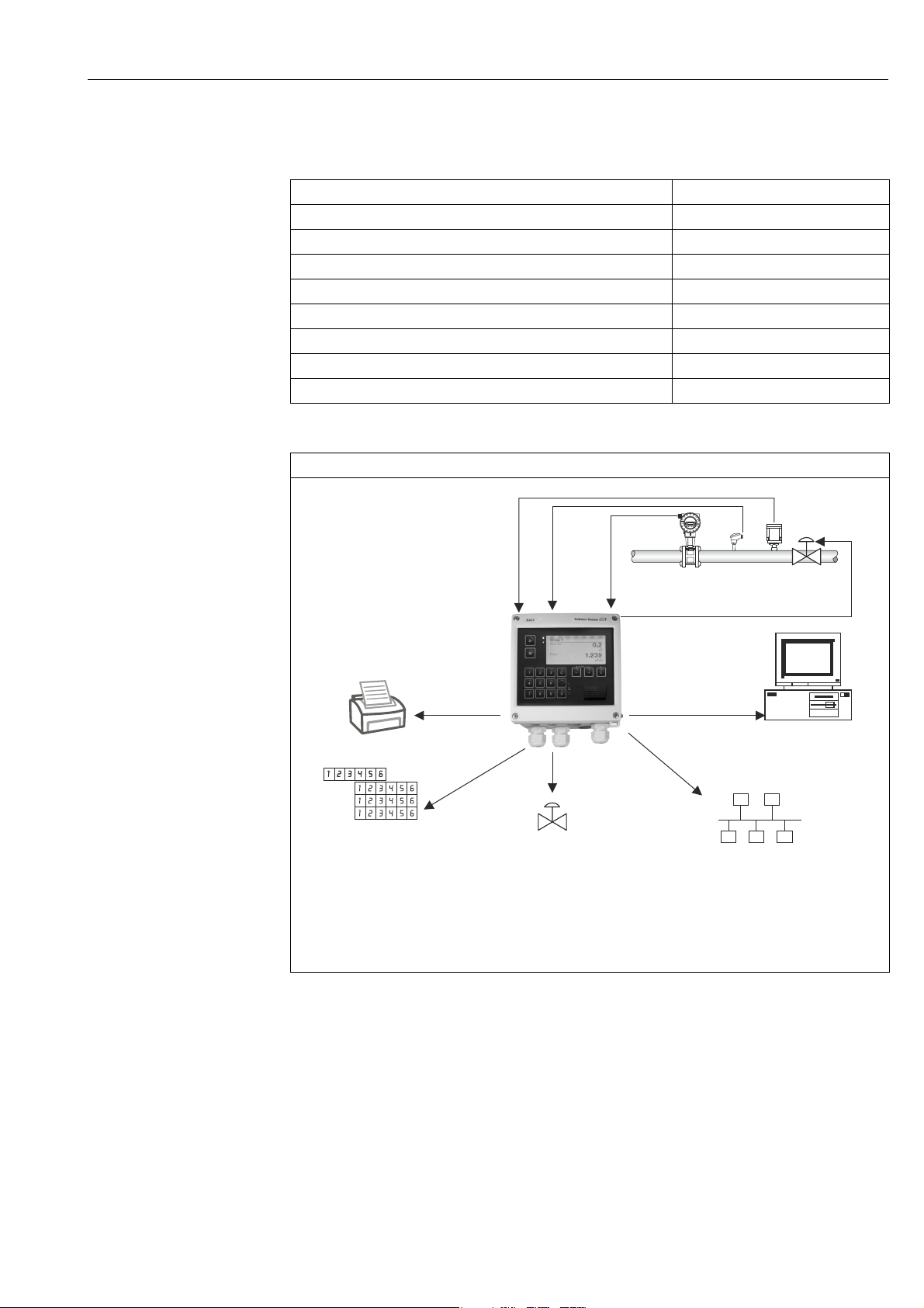
Batch Controller RA33
Q
T
ρ
RS232
Interfaces (USB, Ethernet)
Open collector /
pulse output
Analog output
Counter
Relay
outputs
Ethernet, web server
ModBus TCP
RTUModBus
Valve
Printer
Brief overview
For quick and easy commissioning:
Safety instructions ä 6
▾
Installation ä 10
▾
Wiring ä 15
▾
Display and operating elements ä 22
▾
Commissioning ä 26
Applications for the batch controller
Endress+Hauser 3
1: Brief overview of applications
a0014548-EN
Page 4

Batch Controller RA33
4 Endress+Hauser
Page 5

Batch Controller RA33
Table of contents
1 Safety instructions . . . . . . . . . . . . . . . . . . 6
1.1 Designated use . . . . . . . . . . . . . . . . . . . . . . . . . . . . . 6
1.2 Installation, commissioning and operation . . . . . . 6
1.3 Operational safety . . . . . . . . . . . . . . . . . . . . . . . . . . . 6
1.4 Return . . . . . . . . . . . . . . . . . . . . . . . . . . . . . . . . . . . . . 6
1.5 Notes on safety conventions and icons . . . . . . . . . 7
2 Identification . . . . . . . . . . . . . . . . . . . . . . 8
2.1 Device tag . . . . . . . . . . . . . . . . . . . . . . . . . . . . . . . . . . 8
2.2 Scope of delivery . . . . . . . . . . . . . . . . . . . . . . . . . . . . 8
2.3 Certificates and approvals . . . . . . . . . . . . . . . . . . . . 9
3 Installation . . . . . . . . . . . . . . . . . . . . . . . 10
3.1 Incoming acceptance, transport and storage . . . 10
3.2 Dimensions . . . . . . . . . . . . . . . . . . . . . . . . . . . . . . 10
3.3 Installation . . . . . . . . . . . . . . . . . . . . . . . . . . . . . . . 11
3.4 Installation . . . . . . . . . . . . . . . . . . . . . . . . . . . . . . . 12
3.5 Post-installation check . . . . . . . . . . . . . . . . . . . . . 14
4 Wiring . . . . . . . . . . . . . . . . . . . . . . . . . . . 15
4.1 Connection requirements . . . . . . . . . . . . . . . . . . . 15
4.2 Quick wiring guide . . . . . . . . . . . . . . . . . . . . . . . . 15
4.3 Connecting the sensors . . . . . . . . . . . . . . . . . . . . 17
4.4 Outputs . . . . . . . . . . . . . . . . . . . . . . . . . . . . . . . . . . 19
4.5 Communication . . . . . . . . . . . . . . . . . . . . . . . . . . . 20
4.6 Post-connection check . . . . . . . . . . . . . . . . . . . . . 21
9.4 Output function test . . . . . . . . . . . . . . . . . . . . . . . . 52
9.5 Spare parts . . . . . . . . . . . . . . . . . . . . . . . . . . . . . . . . 53
9.6 Return . . . . . . . . . . . . . . . . . . . . . . . . . . . . . . . . . . . 55
9.7 Disposal . . . . . . . . . . . . . . . . . . . . . . . . . . . . . . . . . . 55
10 Technical data . . . . . . . . . . . . . . . . . . . . 56
11 Appendix . . . . . . . . . . . . . . . . . . . . . . . . 65
11.1 Operating functions and parameters . . . . . . . . . . 65
11.2 Icons . . . . . . . . . . . . . . . . . . . . . . . . . . . . . . . . . . . . . 79
11.3 Units used in the device . . . . . . . . . . . . . . . . . . . . . 80
11.4 Definition of important system units . . . . . . . . . . 81
Index . . . . . . . . . . . . . . . . . . . . . . . . . . . . 82
5 Operation. . . . . . . . . . . . . . . . . . . . . . . . . 22
5.1 General notes for operation . . . . . . . . . . . . . . . . . 22
5.2 Display and operating elements . . . . . . . . . . . . . 22
5.3 Operating matrix . . . . . . . . . . . . . . . . . . . . . . . . . . 25
6 Commissioning. . . . . . . . . . . . . . . . . . . . 26
6.1 Quick commissioning/make it run . . . . . . . . . . . 26
6.2 Applications . . . . . . . . . . . . . . . . . . . . . . . . . . . . . . 26
6.3 Configuring the basic parameters/general device
functions . . . . . . . . . . . . . . . . . . . . . . . . . . . . . . . . 34
6.4 Optional device settings/special functions . . . . 45
7 Maintenance. . . . . . . . . . . . . . . . . . . . . . 46
8 Accessories . . . . . . . . . . . . . . . . . . . . . . . 46
8.1 Device-specific accessories . . . . . . . . . . . . . . . . . . 46
8.2 Communication-specific accessories . . . . . . . . . 46
8.3 Service-specific accessories . . . . . . . . . . . . . . . . . 47
8.4 System components . . . . . . . . . . . . . . . . . . . . . . . 48
9 Troubleshooting. . . . . . . . . . . . . . . . . . .49
9.1 Instrument diagnostics and troubleshooting . . . 49
9.2 Error messages . . . . . . . . . . . . . . . . . . . . . . . . . . . 50
9.3 Diagnosis list . . . . . . . . . . . . . . . . . . . . . . . . . . . . . 51
Endress+Hauser 5
Page 6

Safety instructions Batch Controller RA33
1 Safety instructions
Safe operation of the device is only guaranteed if the Operating Instructions have been read
and the safety instructions they contain have been observed.
1.1 Designated use
The batch controller is a batching and dosing manager for the batching of any media or
mineral oils.
– The manufacturer cannot take responsibility for any damage caused by misuse of the
device. It is not permitted to make any changes or reconstruction to the device.
– The device may be operated in built-in state only.
1.2 Installation, commissioning and operation
The batch controller is safely manufactured using state-of-the-art technology and complies
with the respective regulations and EU Directives. The device could be dangerous if it is
incorrectly installed or used.
Installation, wiring and maintenance of the device must be carried out only by trained,
skilled personnel authorized to perform such work and instructed by the facility's owneroperator. The skilled personnel must have read and understood these Operating Instructions
and it is mandatory for them to follow the instructions they contain. The operator must
ensure that the measuring system is correctly wired in accordance with the wiring diagrams.
When the housing cover is removed, the shock protection is disabled (danger of
electrocution). The housing may be opened by trained skilled personnel only.
The batch controller may be operated in a closed and secure state only.
1.3 Operational safety
Technical improvement
The manufacturer reserves the right to improve and update the technical details. For details
of improvements or additions to these instructions, please contact your local sales
organization.
1.4 Return
For a return, e.g. in case of repair, the device must be sent in protective packaging. The
original packaging offers the best protection. Repairs must only be carried out by your
supplier's service organization.
When sending for repair, enclose a note with a description of the error and the
application.
6 Endress+Hauser
Page 7
Batch Controller RA33 Safety instructions
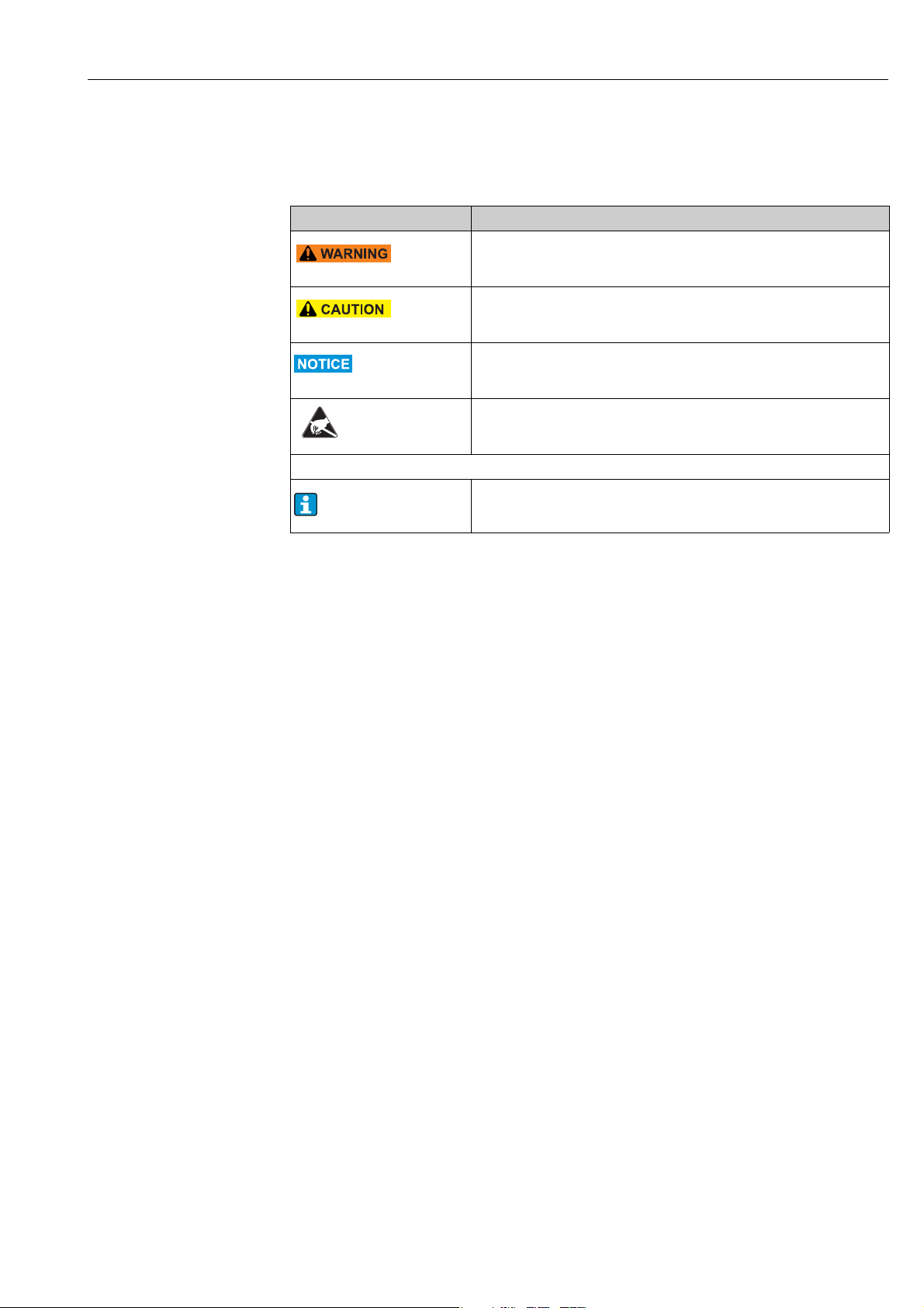
1.5 Notes on safety conventions and icons
The safety instructions in these Operating Instructions are labeled with the following safety
icons and symbols:
Symbol Meaning
WARNING!
A0011190-EN
A0011191-EN
A0011192-EN
This symbol alerts you to a dangerous situation. Failure to avoid this situation
can result in serious or fatal injury.
CAUTION!
This symbol alerts you to a dangerous situation. Failure to avoid this situation
can result in minor or medium injury.
NOTE
This symbol contains information on procedures and other facts which do not
result in personal injury.
ESD - Electrostatic discharge
Protect the terminals from electrostatic discharge. Failure to observe this may
result in destruction or malfunction of parts of the electronics.
Additional information, tip
A0011193
Endress+Hauser 7
Page 8
Identification Batch Controller RA33
2 Identification
2.1 Device tag
2.1.1 Nameplate
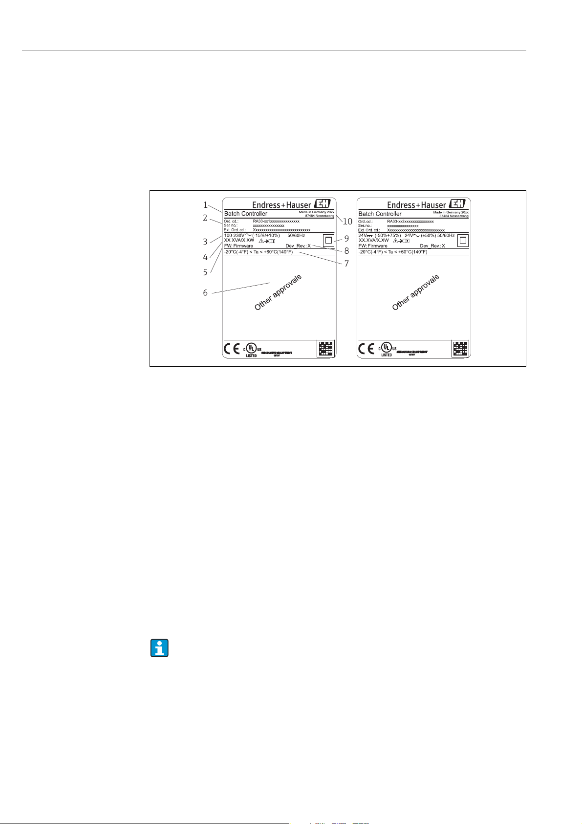
Compare the nameplate on the device with the following diagram:
a0014625
2: Nameplate of the batch controller (example)
1Device tag
2 Order code and serial number
3 Supply voltage
4Power consumption
5 Firmware version
6 Approvals, if available
7 Ambient temperature range
8Device revision
9 Device protected by double or reinforced seal
10 Place and year of manufacture
2.2 Scope of delivery
The scope of delivery of the batch controller comprises:
• Batch controller (field housing)
•Wall mountig plate
• Brief Operating Instructions in paper form
• Optional 3 pcs. connection clamps (5 positions apiece)
• Optional interface cable and DVD set with FieldCare Device Setup parameter configuration
software
• Optional Field Data Manager software
•Optional mounting hardware for DIN rail, panel mounting, pipe mounting
• Optional overvoltage protection
Please note the device accessories in Section 8 ’Accessories’.
8 Endress+Hauser
Page 9

Batch Controller RA33 Identification
2.3 Certificates and approvals
CE mark, Declaration of Conformity
The device is safely built and tested according to state-of-the-art technology and has left the
factory in perfect condition as regards technical safety. The device complies with the
applicable standards and regulations in accordance with EN 61010-1 "Safety requirements
for electrical equipment for measurement, control and laboratory use".
Thus, the device described in these Operating Instructions meets the legal requirements of
the EU Directives. The manufacturer confirms successful testing of the device by affixing to
it the CE mark.
Endress+Hauser 9
Page 10
Installation Batch Controller RA33
3Installation
3.1 Incoming acceptance, transport and storage
The permitted environmental, storage and transportation conditions must be complied with.
For detailed specifications, refer to the "Technical data" chapter ( ä 56).
3.1.1 Incoming acceptance
On receipt of the goods, check the following points:
• Are the packaging or contents damaged?
• Are the delivered goods complete? Compare the scope of delivery with your order
information.
3.1.2 Transport and storage
Observe the following points:
• Pack the device in such a way as to protect it reliably against impact for storage (and
transportation). The original packaging provides optimum protection.
• The permitted storage temperature range is -40 to +85 °C (-40 to +185 °F); storage in the
temperature limit ranges is possible for a limited time only (maximum of 48 hours).
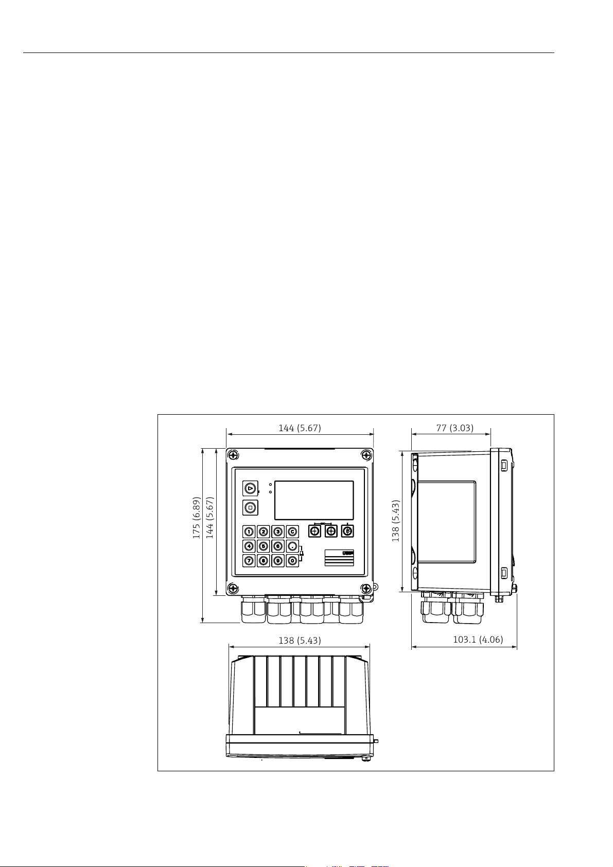
3.2 Dimensions
a0014119
3: Dimensions of the device in mm (in)
10 Endress+Hauser
Page 11
Batch Controller RA33 Installation
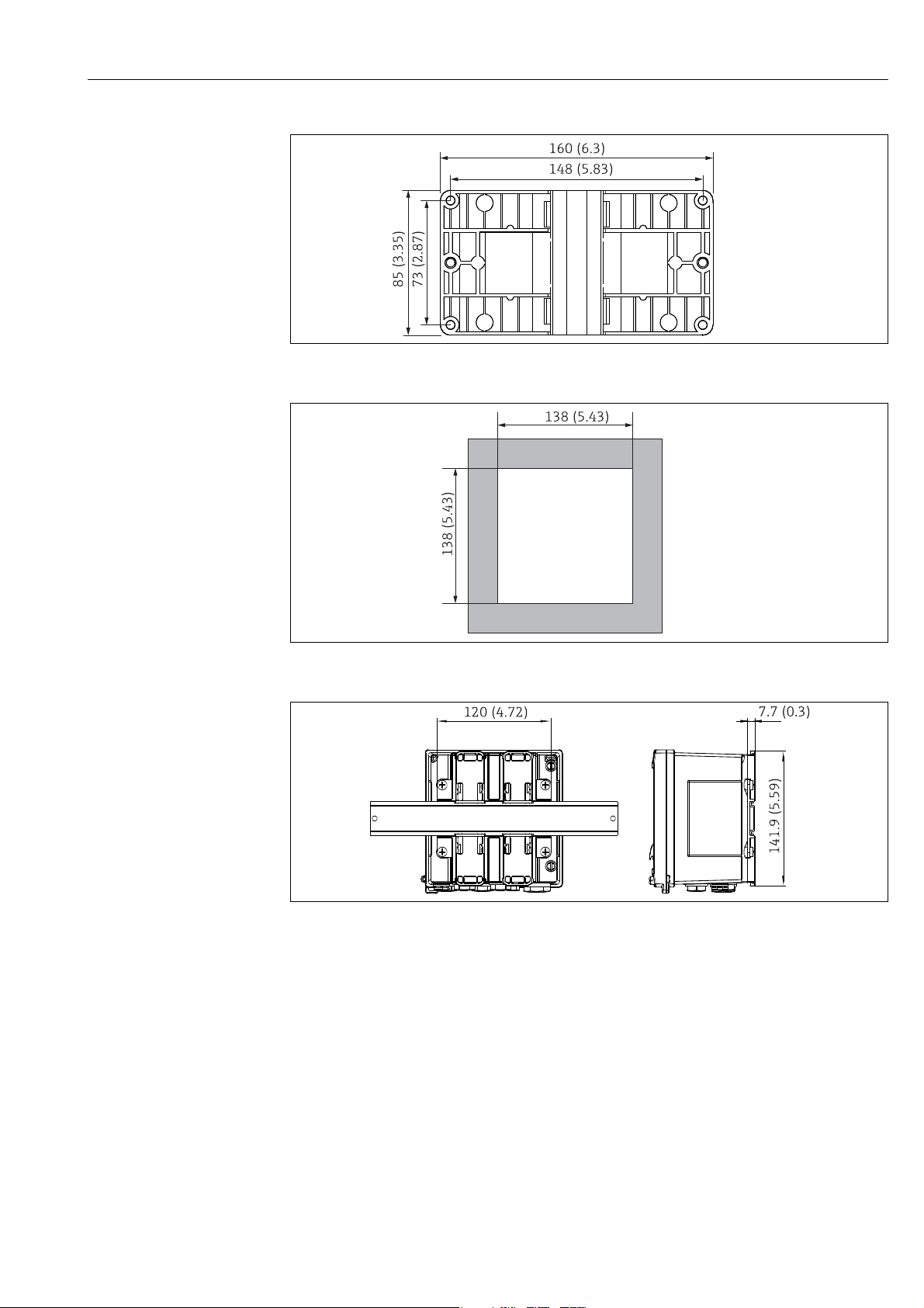
a0014169
4: Mounting plate for wall, pipe and panel mounting, dimensions in mm (in)
a0014171
5: Panel cutout, dimensions in mm (in)
a0014610
6: Dimensions of the DIN rail adapter in mm (in)
3.3 Installation
With the appropriate accessories ä 46, the device with field housing is suitable for wall
mounting, pipe mounting, panel mounting and DIN rail installation.
The orientation is determined by the legibility of the display. Connections and outputs are
fed out of the bottom of the device. The pipes are connected via coded clamps.
Operating temperature range:
-20 to 60 °C (-4 to 140 °F)
Endress+Hauser 11
Page 12
Installation Batch Controller RA33
NOTICE
High temperatures reduce the operating life of the device
‣ To prevent heat build-up, do not expose the device to extreme heat or strong direct
sunshine.
‣ Operation in the upper temperature limit range decreases the operating life of the
display.
3.4 Installation
3.4.1 Wall mounting
1. Use the mounting plate as the template for drilled holes, dimensions å 4, ä 11
2. Attach the batch controller to the mounting plate and fasten it in place from the rear
using 4 screws.
3. Fasten the mounting plate to the wall using 4 screws.
a0014170
7: Wall mounting
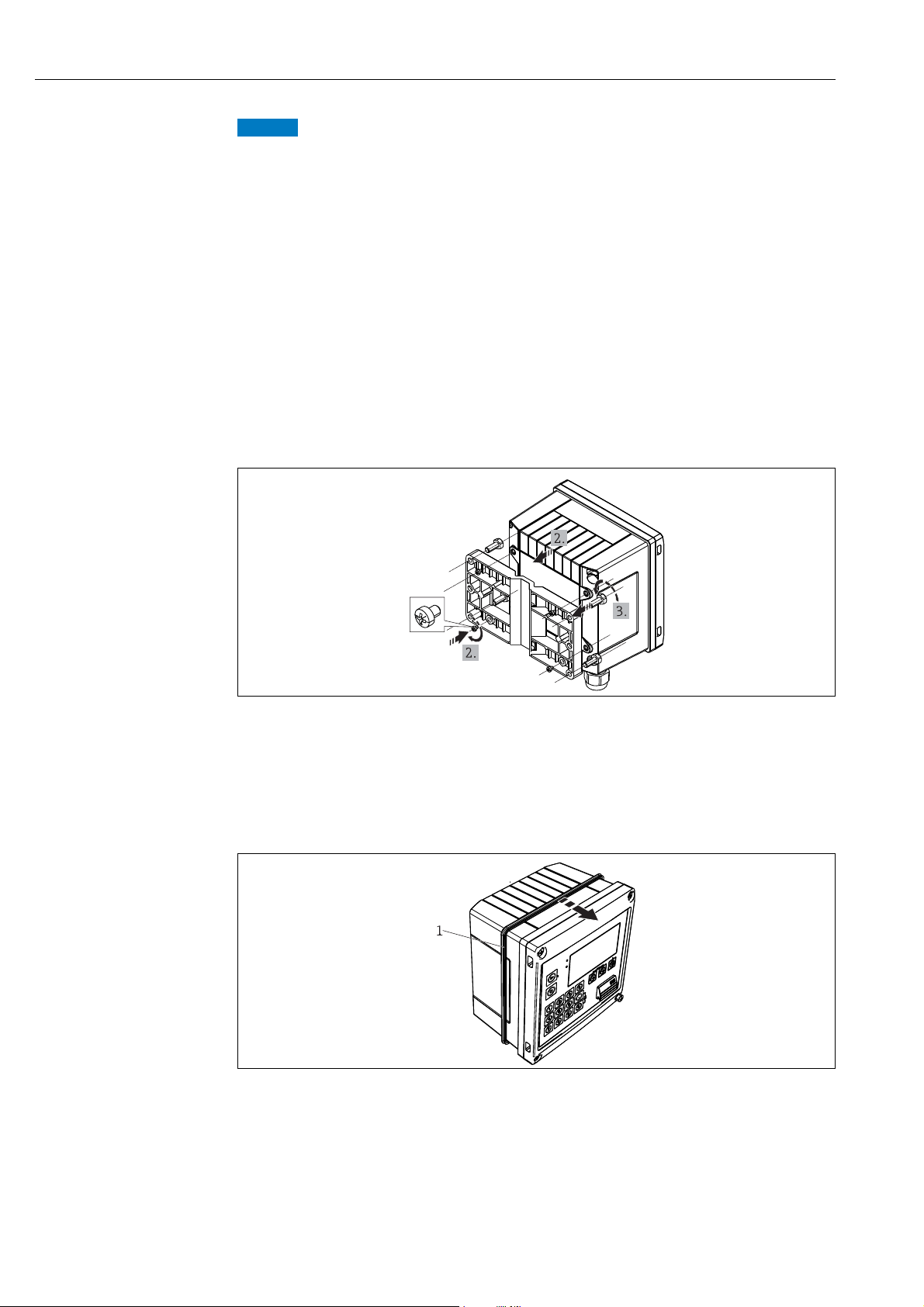
3.4.2 Panel mounting
1. Make the panel cutout in the required size, dimensions å 5, ä 11.
2. Attach the seal (item 1) to the housing.
a0014283
8: Panel mounting
3. Screw the threaded rods (item 2) into the mounting plate (dimensions å 4, ä 11).
12 Endress+Hauser
Page 13
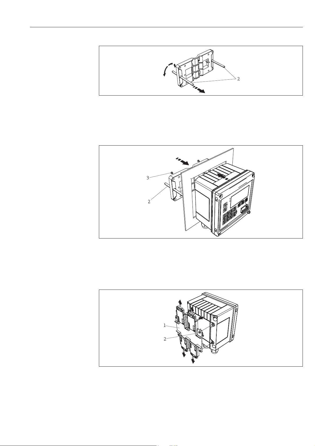
Batch Controller RA33 Installation
a0014173
9: Preparing the mounting plate for panel mounting
4. Push the device into the panel cutout from the front and attach the mounting plate to
the device from the rear using the 4 screws provided (item 3).
5. Fasten the device in place by tightening the threaded rods.
a0014284
10: Panel mounting
3.4.3 Support rail/DIN rail (to EN 50 022)
1. Fasten the DIN rail adapter (item 1, dimensions å 6, ä 11) to the device using the
screws provided (item 2) and open the DIN rail clips.
a0014176
11: Preparing for DIN rail mounting
2. Attach the device to the DIN rail from the front and close the DIN rail clips.
Endress+Hauser 13
Page 14
Installation Batch Controller RA33
a0014177
12: DIN rail mounting
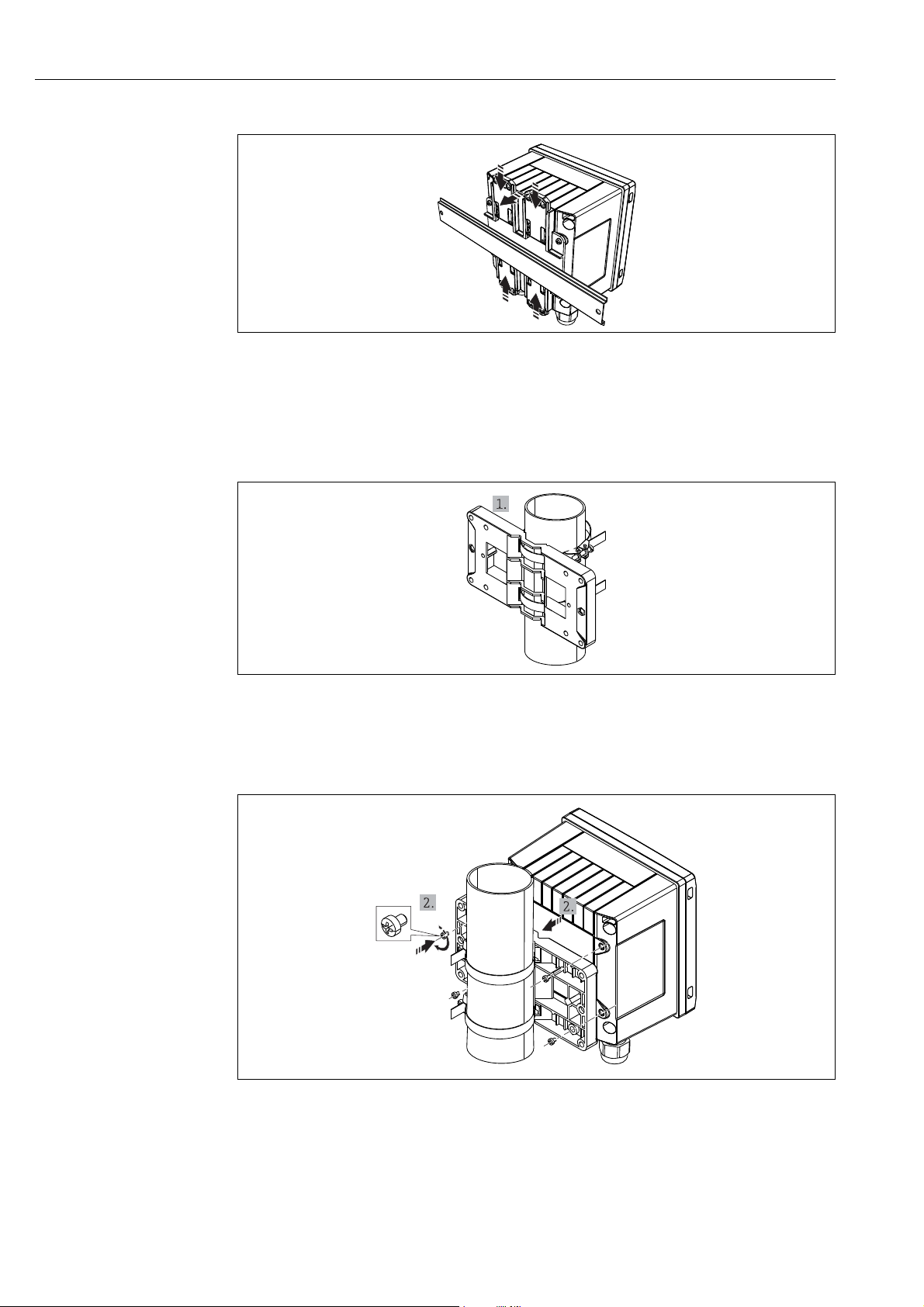
3.4.4 Pipe mounting
1. Pull the steel belts through the mounting plate (dimensions å 4, ä 11) and fasten
them to the pipe.
13: Preparing for pipe mounting
2. Attach the device to the mounting plate and fasten it in place using the 4 screws
provided.
14: Pipe mounting
a0014178
a0014179
3.5 Post-installation check
For installing the batch controller and the associated temperature sensors, observe the
general installation instructions according to EN 1434 Part 6.
14 Endress+Hauser
Page 15
Batch Controller RA33 Wiring
WARNING
!
CAUTION
!
4 Wiring
4.1 Connection requirements
Danger! Electric voltage!
‣ The entire connection of the device must take place while the device is de-energized.
Incorrect power supply can cause malfunctions
‣ Before commissioning the device, make sure that the supply voltage matches the voltage
specifications on the nameplate.
‣ Provide a suitable switch or power-circuit breaker in the building installation. This switch
must be installed close to the device (so that it is easily accessible) and marked as a circuit
breaker.
‣ An overload protection unit (rated current = 10 A) is required for the power cable.
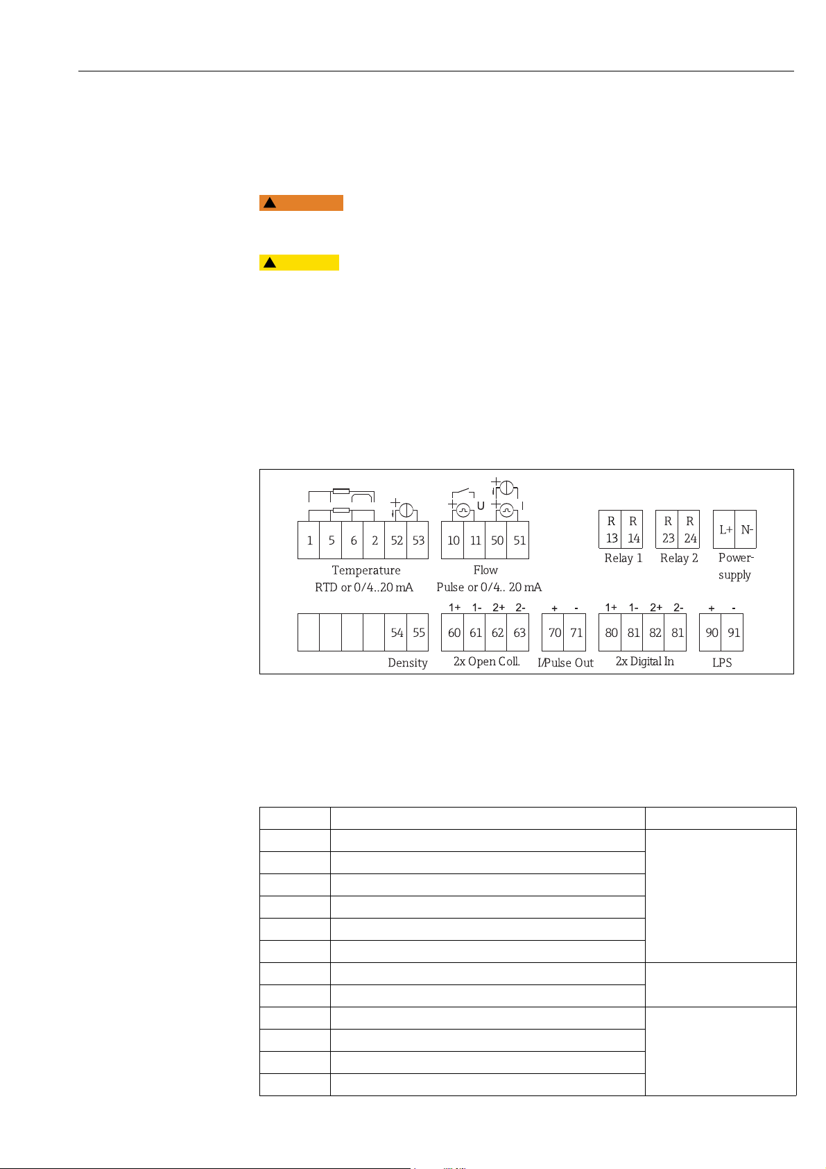
4.2 Quick wiring guide
15: Connection diagram of the batch controller
For the connection of the communication interfaces, see the "Communication" section,
ä 20.
Terminal assignment
Terminals Terminal assignment Inputs
1 + RTD power supply Temperature, ä 19
2 - RTD power supply
5+ RTD sensor
6- RTD sensor
52 + 0/4 to 20 mA input
53 Ground for 0/4 to 20 mA input
54 + 0/4 to 20 mA input Density
55 Ground for 0/4 to 20 mA input
10 + pulse input (voltage or contact) Flow, ä 17
11 - pulse input (voltage or contact)
50 + 0/4 to 20mA or current pulse (PFM)
51 Ground for 0/4 to 20 mA input, flow
(Optionally RTD or current
input)
(Current input)
(Optionally pulse or current
input)
a0014120
Endress+Hauser 15
Page 16
Wiring Batch Controller RA33
80 + digital input 1 (switch input) • Time synchronization
81 - digital input (terminal 1)
82 + digital input 2 (switch input) • Time synchronization
81 - digital input (terminal 2)
60 + status/pulse output 1 (open collector) Batch control: pump/valve,
61 - status/pulse output 1 (open collector)
62 + status/pulse output 2 (open collector)
63 - status/pulse output 2 (open collector)
70 + 0/4 to 20mA/pulse output Current values (e.g. power) or
71 0/4 to 20mA/pulse output
13 Relay 1 normally open (NO) Batch control: pump/valve,
14 Relay 1 normally open (NO)
23 Relay 2 normally open (NO)
24 Relay 2 normally open (NO)
90 24V sensor power supply (LPS) 24 V power supply
91 Power supply ground
L/+ L for AC
+ for DC
N/- N for AC
- for DC
• Start batch
• Stop batch
•Reset batch
Outputs
volume counter, signal for end
of batch, fault
counter values (e.g. energy)
fault
(e.g. for sensor power supply)
Power supply
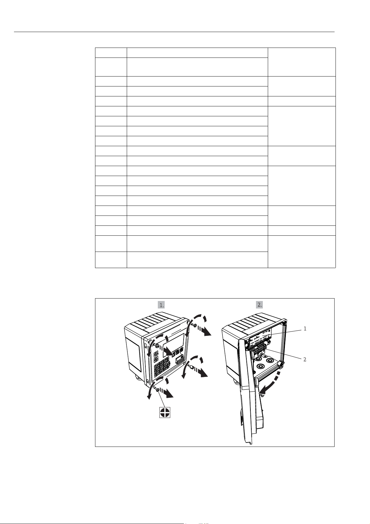
4.2.1 Open housing
16: Opening the housing of the batch controller
1 Terminal assignment labeling
2Terminals
a0014368
16 Endress+Hauser
Page 17
Batch Controller RA33 Wiring
4.3 Connecting the sensors
4.3.1 Flow
Sensors for volume or mass flow measurement can be connected to the batch controller.
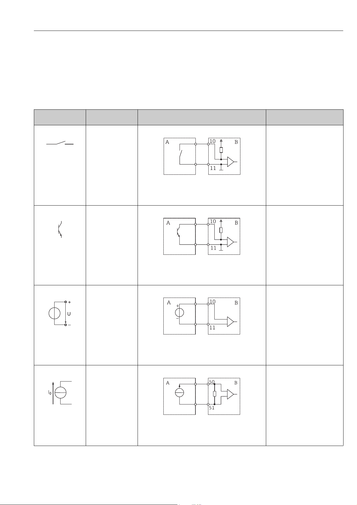
Connecting flow sensors with a pulse output
Pulse output of the
flow sensor
Mechanical contact
a0015360
Open collector (NPN)
a0015361
Active voltage
Setting at the Rx33 Electrical connection Notes
Pulse ID/IE up to 25 Hz
As an alternative, it is possible to
choose "Pulse IB/IC+U" up to 25 Hz.
The current flow via the contact is
then lower (approx. 0.05 mA
instead of approx. 9 mA).
Advantage: lower power
consumption, disadvantage: less
immunity to interference.
a0015354
A = Sensor
B = Rx33
Pulse ID/IE up to 25 Hz
or up to 12.5 kHz
As an alternative, it is possible to
choose "Pulse IB/IC+U". The current
flow via the transistor is then lower
(approx. 0.05 mA instead of approx.
9 mA). Advantage: lower power
consumption, disadvantage: less
immunity to interference.
a0015355
A = Sensor
B = Rx33
Pulse IB/IC+U
The switching threshold is between
1V and 2 V.
a0015362
a0015356
A = Sensor
B = Rx33
Active current
Pulse I
The switching threshold is between
8mA and 13 mA.
a0015363
a0015357
A = Sensor
B = Rx33
Endress+Hauser 17
Page 18
Wiring Batch Controller RA33
Pulse output of the
flow sensor
Namur sensor (as per
EN60947-5-6)
Setting at the Rx33 Electrical connection Notes
Pulse ID/IE up to 25 Hz
or up to 12.5 kHz
No monitoring for short circuit or
line break takes place.
a0015359
1 = Sensor
2 = Rx33
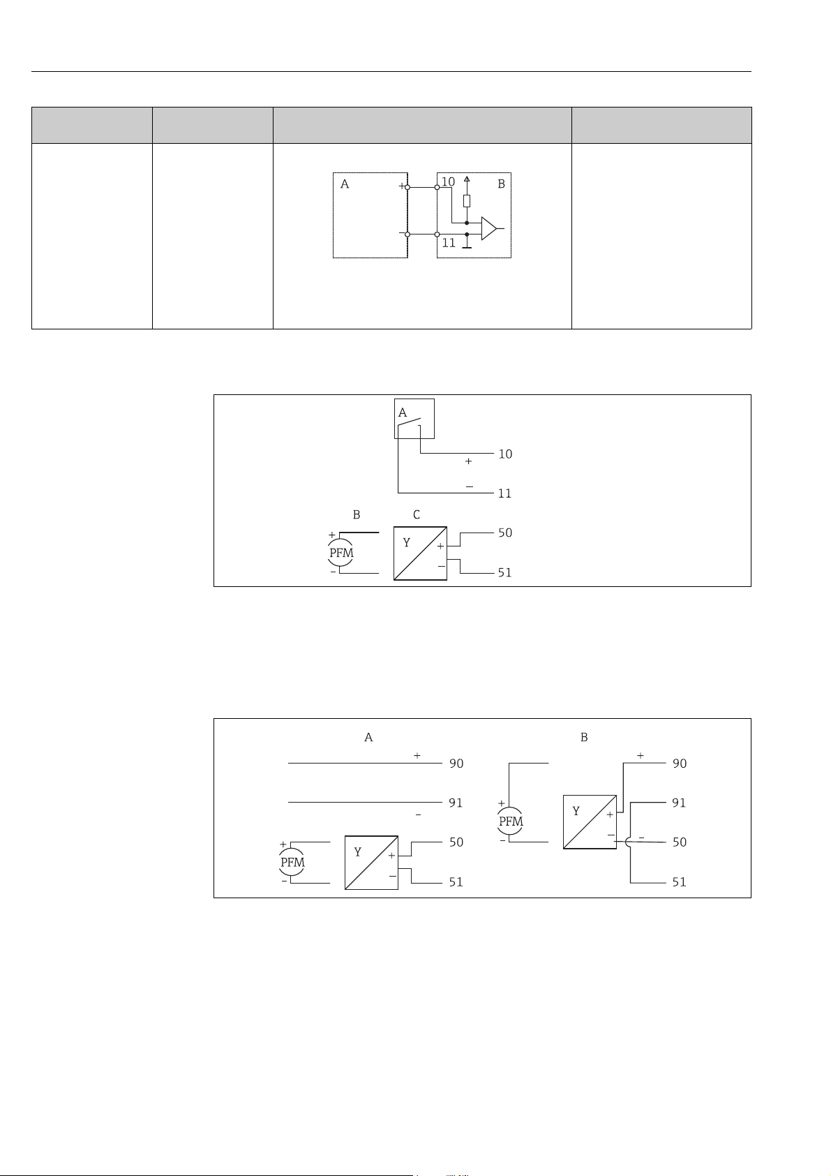
Flow sensors with external power supply
17: Connecting a flow sensor
A Voltage pulses or contact sensors including EN 1434 Type IB, IC, ID, IE
B Current pulses
C 0/4 to 20 mA signal
Flow sensors with power supply via the batch controller
18: Connecting active flow sensors
A4-wire sensor
B2-wire sensor
a0013521
a0014180
18 Endress+Hauser
Page 19
Batch Controller RA33 Wiring
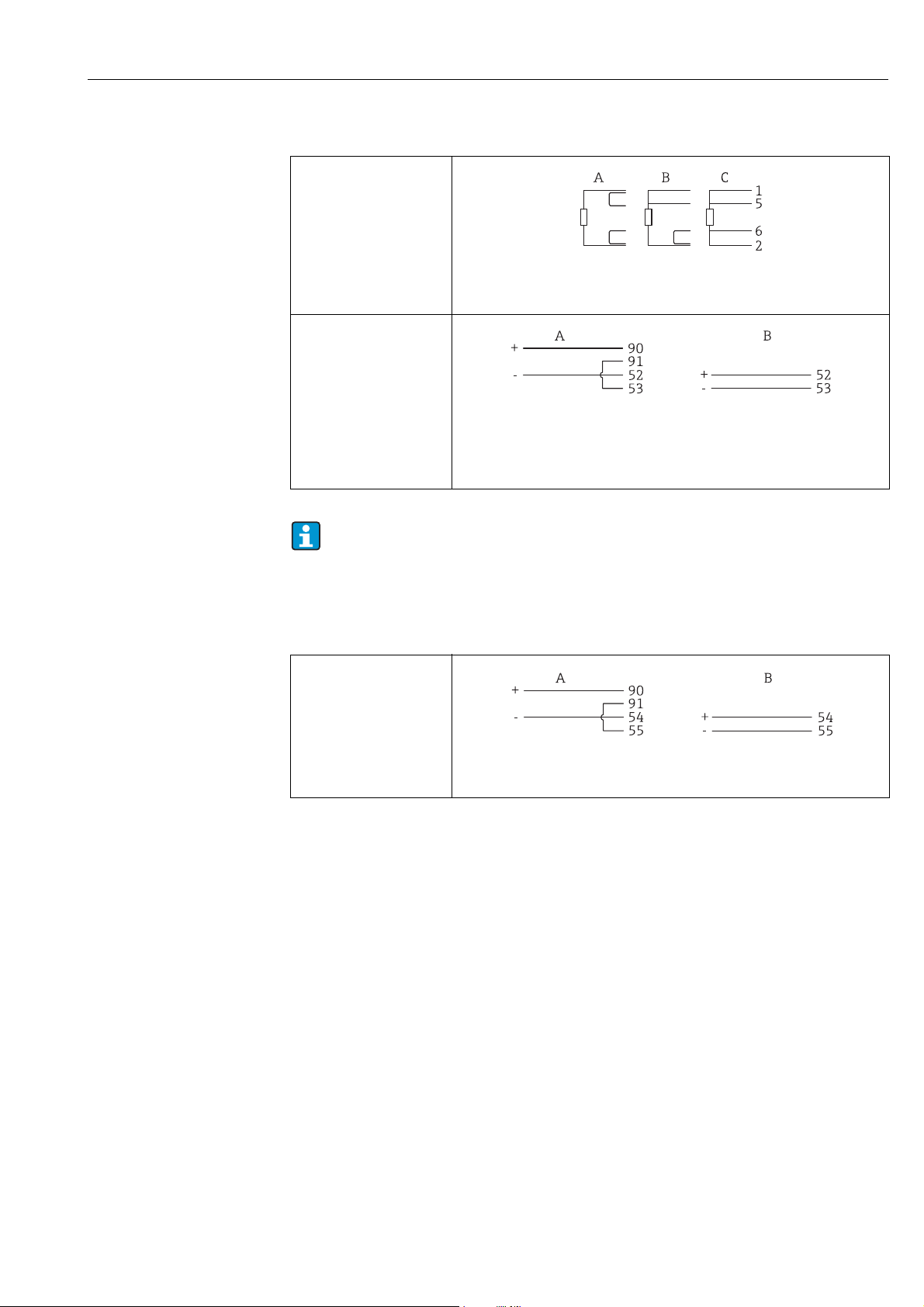
4.3.2 Temperature
Connecting the RTD sensors
A0014529
A = 2-wire connection, B= 3-wire connection, C = 2-wire connection
Terminals 1, 2, 5, 6: temperature
Temperature transmitter
connection
A0014528
A = without external power supply of the transmitter, B = with external power
supply of the transmitter
Terminals 90, 91: transmitter power supply
Terminals 52, 53: temperature
To ensure the highest level of accuracy, we recommend using the RTD 4-wire
connection, as this compensates for measurement inaccuracies caused by the
mounting location of the sensors or the line length of the connecting cables.
Density
Density sensor connection
a0015152
A = without external power supply of the density sensor, B = with external power
supply of the density sensor
4.4 Outputs
4.4.1 Analog output (active)
This output can be used either as a 0/4 to 20 mA current output or as a voltage pulse output.
The output is galvanically isolated. For the terminal assignment, refer to ä 15.
4.4.2 Pulse output (active)
Active voltage pulses are output at the pulse output.
Voltage level:
• 0 to 2 V corresponds to Low level
• 15 to 20 V corresponds to High level
Maximum output current: 22 mA
4.4.3 Open collector output
The two digital outputs can be used as status or pulse outputs. Make the selection in the
following menus: Setup → Advanced setup or Expert → Outputs → Open collector
Endress+Hauser 19
Page 20
Wiring Batch Controller RA33
4.5 Communication
The USB interface is always active and can be used independently of other interfaces.
Parallel operation of multiple optional interfaces, e.g. fieldbus and Ethernet, is not
possible.
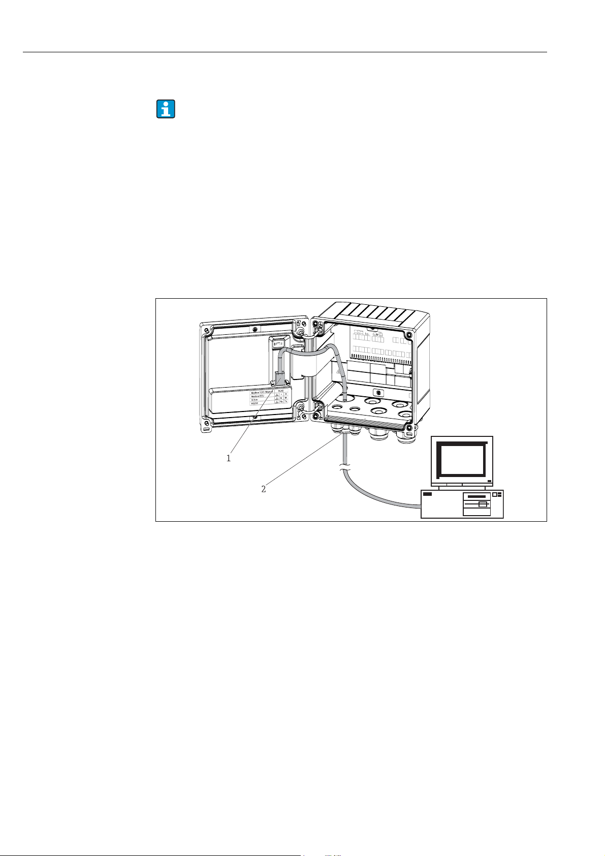
4.5.1 Ethernet TCP/IP (optional)
The Ethernet interface is galvanically isolated (testing voltage: 500 V). A standard patch
cable (e.g. CAT5E) can be used to connect the Ethernet interface. A special cable gland is
available for this purpose which allows users to guide pre-terminated cables through the
housing. Via the Ethernet interface, the device can be connected using a hub or a switch or
directly to office equipment.
• Standard: 10/100 Base-T/TX (IEEE 802.3)
• Socket: RJ-45
• Max. line length: 100 m
a0014600
19: Ethernet TCP/IP, Modbus TCP connection
1 Ethernet, RJ45
2 Cable entry for Ethernet cable
4.5.2 Modbus TCP (optional)
The Modbus TCP interface is used to connect the device to higher-order systems to transmit
all measured values and process values. The Modbus TCP interface is physically identical to
the Ethernet interface ( ä 20). Connection å 19, ä 20.
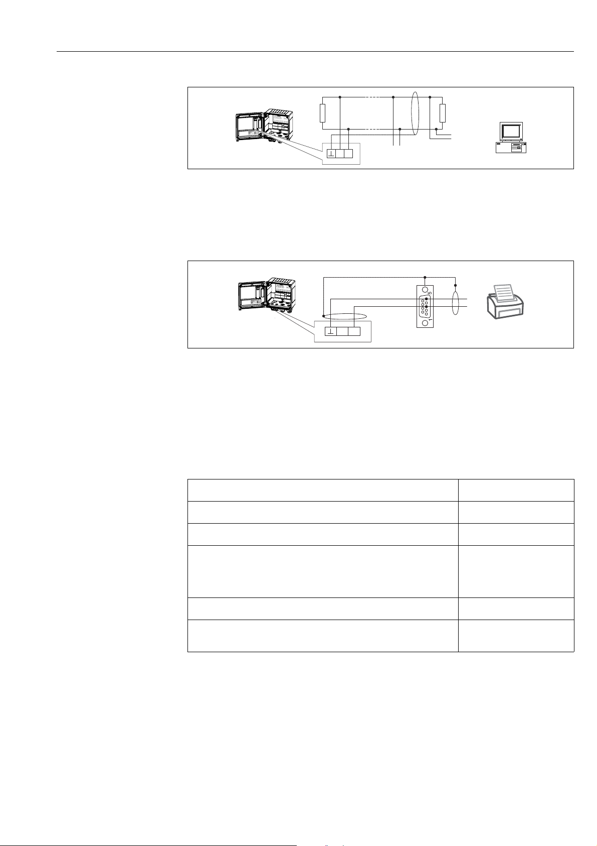
4.5.3 Modbus RTU (optional)
The Modbus RTU (RS-485) interface is galvanically isolated (testing voltage: 500 V) and
used to connect the device to higher-order systems to transmit all measured values and
process values. It is connected via a 3-pin plug-in terminal in the housing cover.
20 Endress+Hauser
Page 21
Batch Controller RA33 Wiring
-
+
RxD/TxD (+)
RxD/TxD (-)
R
L
R
L
further instrumentation
GND
Rx
5
3
Rx
Tx
a0014603-EN
20: Modbus RTU connection
4.5.4 Printer interface / RS232 (optional)
The printer/RS232 interface is galvanically isolated (testing voltage: 500 V) and is used to
connect a printer. It is connected via a 3-pin plug-in terminal in the housing cover.
21: Printer connection via RS232
The following printers have been tested with the batch controller:
• GeBE MULDE Mini thermal printer
4.6 Post-connection check
After completing the device's electrical installation, carry out the following checks:
Device status and specifications Notes
Is the device or cable damaged (visual inspection)? -
Electrical connection Notes
Does the supply voltage match the specifications on the nameplate? 100 to 230 V AC/DC (±10%)
(50/60 Hz)
24 V DC (-50% / +75%)
24 V AC (±50%) 50/60 Hz
Are the mounted cables relieved of tension? -
Are the power supply and signal cables correctly connected? See wiring diagram on the
housing
a0014602
Endress+Hauser 21
Page 22
Operation Batch Controller RA33
5Operation
5.1 General notes for operation
The batch controller can be configured using keys or using the "FieldCare" operating
software.
The operating software, including the interface cable, is available as an order option, i.e. it is
not part of the basic scope of delivery.
The configuration is locked if the device is locked by the locking switch ( ä 23) or the user
code.
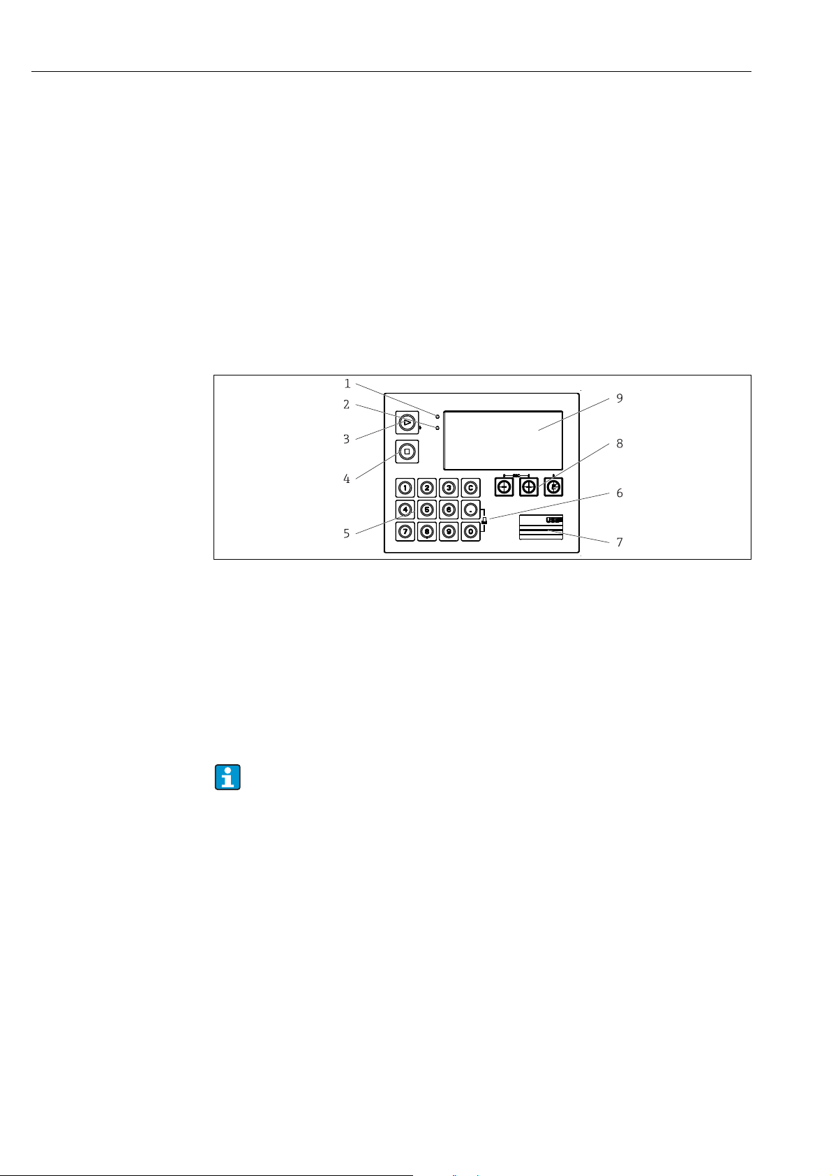
5.2 Display and operating elements
22: Display and operating elements of the batch controller
1LED green, "Operation"
2 LED red, "Fault indicator"
Function keys:
3Start
4 Stop
5 Numerical keypad
6 Start printing
Interface:
7 USB connection for configuration
Operating keys:
8-, +, E
Display:
9160 x80 DOT matrix display
Green LED for voltage, red LED for alarm/error. Green LED is always illuminated as
soon as power is supplied to the device.
Slow flashing of the red LED (approx. 0.5 Hz): the device has been put into
bootloader mode.
Fast flashing of the red LED (approx. 2 Hz): in normal operation: maintenance
required. During firmware update: data transmission active.
Red LED illuminated constantly: device error.
5.2.1 Operating elements
a0014276
3 operating keys, "-", "+", "E".
Esc/back function: press "-" and "+" simultaneously.
Enter/confirm entry: press "E"
22 Endress+Hauser
Page 23
Batch Controller RA33 Operation
14 function keys:
Start/stop function: Pressing the "Start" button starts a batching operation. Press the "Stop"
button once to pause the batching operation currently in progress. Press "Stop" a second time
to abort the batch. Pressing start again restarts the batch cycle.
C function: Press "C" when batching is stopped to reset the counters on the display to their
original values.
Print function: Press "0" and "." simultaneously to print out the last batch cycle. The "RS232
printer interface" feature must be purchased to be able to use this function.
Locking switch
a0015168
23: Locking switch
1 Locking switch on the back of the housing cover
5.2.2 Function for entering a value for the preset counter
A value for the preset counter can be entered any time. This value can either be entered in
the Display menu, or by pressing one of the keys 0-9 or period. It does not matter whether a
batching process is currently active when you enter the value. The new preset counter value
is used when the next batching process is started.
If the preset counter is part of a display group, the preset counter value which is valid
for the current batch is always displayed. If the value is changed when the batching
process is stopped, the new value appears immediately on the display. However, if
the value is changed during an active batching operation, the old value of the preset
counter, which still applies for the current batch run, is displayed until this batching
operation is finished. The new value, which is valid for the next batching operation,
is displayed directly afterwards.
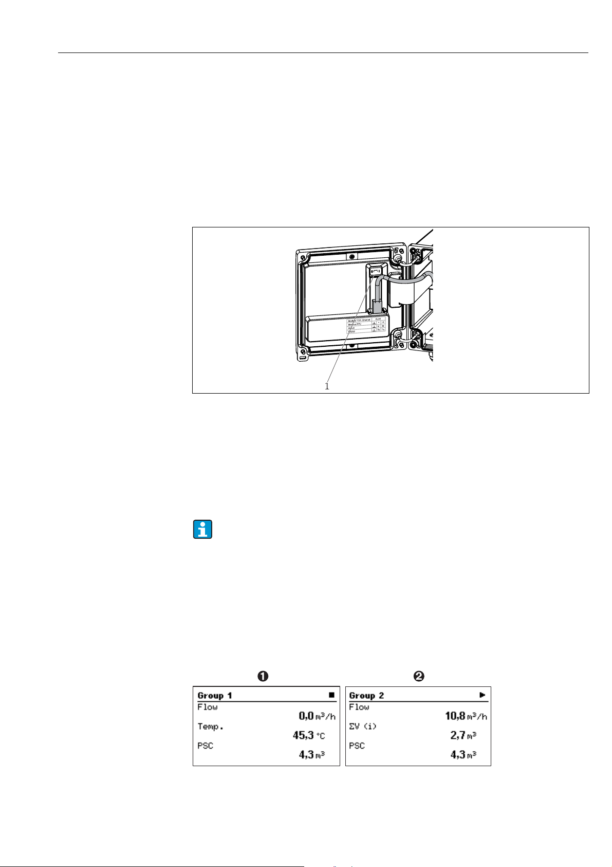
5.2.3 Display
a0014551
24: Display of the batch controller (example)
1: Display group 1: no batch active. Flow, temperature, preset counter
2: Display group 2: batch active. Flow, volume counter, preset counter
Endress+Hauser 23
Page 24

Operation Batch Controller RA33
A list of the icons is provided in the Appendix, ä 79.
5.2.4 "FieldCare Device Setup" operating software
For configuring the device using the FieldCare Device Setup software, connect the device to
your computer via the USB interface.
Establishing a connection
Proceed as follows:
1. Start FieldCare.
2. Connect the device to the computer via USB.
3. Generate project via File/New.
4. Select communication DTM (CDI Communication USB).
5. Add Rx33.
6. Click "Establish connection".
7. Start online configuration.
Carry out the rest of the configuration of the device according to these Operating
Instructions for the device. The entire Setup menu, i.e. all parameters listed in these
Operating Instructions, is also included in the FieldCare Device Setup.
During configuration with FieldCare, the device can enter undefined states! This can
result in undefined switching of outputs and relays.
24 Endress+Hauser
Page 25

Batch Controller RA33 Operation
5.3 Operating matrix
For a complete overview of the operating matrix including all configurable parameters,
ä 65.
Language Drop-down list with all available operating languages. Select the
Display/operation menu • Select the group for display (automatic change or fixed display
Setup menu In this Setup, you can configure the parameters for quick
language of the device.
group)
• Setting for the display brightness and contrast
• Display the stored analyses and batch reports
• Enter a value for the preset counter
• Recipe selection
commissioning of the device. Advanced setup includes all important
parameters for configuring the instrument function.
•Units
•Signal type
• Pulse value, value (for pulse signal
type) or
• Start of measuring range (for current
signal type)
• End of measuring range (for current
signal type)
•Unit
•Counter unit
• Date and time
• Advanced setup (settings that are not essential for basic
operation of the device)
Special settings can be configured via "Expert".
Parameters for
quick commissioning
Diagnostics menu Device information and service functions for a swift device check.
• Diagnostic messages and list
• Event logbook
• Device information
•Simulation
• Measured values, outputs
Expert menu The Expert menu offers access to all operating options of the device,
including fine tuning and service functions.
• Jump directly to parameters via Direct Access (only on the device)
• Service code for displaying service parameters (via PC operating
software only)
•System (settings)
•Inputs
•Outputs
•Application
•Diagnostics
Endress+Hauser 25
Page 26

Commissioning Batch Controller RA33
6 Commissioning
Make sure that all post-connection checks have been carried out before you commission
your device:
• See 'post-installation check', ä 14
• Checklist for 'post-connection check’, ä 21
After the operating voltage is applied, the display and the green LED are illuminated. The
device is now ready to operate and can be configured via the keys or the "FieldCare Device
Setup" parameter configuration software ( ä 24).
Remove the protective foil from the display, as otherwise legibility is impaired.
6.1 Quick commissioning/make it run
For quick commissioning of the "standard" batch controller application, you only have to
enter a few operating parameters in the menu Setup.
Prerequisites for quick commissioning:
• RTD temperature sensor, 4-wire direct connection
Menu/setup
→ Units: Select unit type (SI/US)
→ Signal type: Select the signal type for flow (pulse or current)
→ Unit: Select the flow unit
3
→ Counter unit: Specify the unit for the flow counter, e.g. m
→ Pulse value, value: Enter the unit and value for the pulse value of the flow transmitter
(for "pulse" signal type)
→ Meas. range start and Meas. range end (for "current" signal type)
→ Date/time: Set the date and time
The device is now operational and ready to control batching.
You can configure device functions, such as data logging, tariff function, bus connection and
the scaling of current inputs for flow or temperature, in the "Advanced setup" menu.
, kg
6.2 Applications
The device is suitable for the automatic control of slow batch processes with a
duration of longer than 10 seconds.
The following is an explanation of the application possibilities, including brief operating
instructions for the respective device settings.
• Batch controller with flow measurement and 1-stage batching, ä 27
• Batch controller with flow measurement and 2-stage batching, ä 28
• Batch controller with API temperature compensation, ä 29
• Batch controller with API temperature/density compensation, ä 30
• Batch controller with mass calculation, ä 31
• Batch controller with volume calculation, ä 32
•Manual batching, ä 33
26 Endress+Hauser
Page 27

Batch Controller RA33 Commissioning
E
Storage
Tank
Batch controller
Flow meter
Valve
Push
button
6.2.1 Batch controller with flow measurement and 1-stage batching
This application describes the standard application of the batch controller RA33. It is
presented as a metering instrument in this application. The flow is measured and the valve
is controlled in such a way that the specified quantity of medium is batched precisely.
a0014354-EN
25: Batch controller with flow measurement and 1-stage batching
Input signals:
Flow, (pulse input or current input)
Output signals:
Valve control (relay or open collector)
Required settings:
a. Flow input: Enter pulse value or measuring range of the 0/4 to 20 mA input.
b. Valve control: Set the choice of filling stages to 1-stage. Assign the selected output to
control the filling stage.
c. Preset counter: Before starting a batch for the first time, a value must be entered for the
preset counter ( ä 23). Otherwise batching cannot commence. The preset counter
defines the quantity of medium which the Batch Controller RA33 batches as precisely
as possible. The last preset counter value to be used is stored in the device and applied
for new batching operations until the value is changed.
d. After-run correction: The first time the automatic after-run correction function of the
Batch Controller RA33 is used, the controller first has to learn what the after-run
quantity is. The after-run quantity is the volume of medium that still flows between the
time the control output switches to the time no more flow is recorded. The after-run
quantity thus depends on the switching delay and valve closing time. The batch
controller tries to correct the switch output by this amount to ensure that the batching
result is as accurate as possible.
To keep excess amounts to a minimum during these initial runs, it is advisable to enter
a value for the manual after-run quantity and to teach the device with smaller test
quantities as medium overflow can be expected.
Display variables:
Preset counter, batch counter, flow, daily, monthly and annual counters and totalizer for
batched quantity, number of batches.
Endress+Hauser 27
Page 28

Commissioning Batch Controller RA33
E
Storage
Tank
Batch controller
Flow meter
Pump
Valves
6.2.2 Batch controller with flow measurement and 2-stage batching
This application describes the standard application of the batch controller. It describes twostage batching with two valves. This application uses one valve with a higher rate of flow and
another valve with a lower rate of flow to dose the medium. The valve with the higher rate
of flow is used for fast filling and is closed earlier so that the device can then dose more
precisely with the second valve.
a0014353-EN
26: Batch controller with flow measurement and 2-stage batching
Input signals:
Flow, (pulse input or current input)
Output signals:
Valve control (relay or open collector)
Pump control (analog output, relay or open collector)
Required settings:
a. Flow input: Enter pulse value or measuring range of the 0/4 to 20 mA input.
b. Valve control: Set the choice of filling stages to 2-stage. Assign the selected outputs to
control the filling stages.
Display variables:
Preset counter, batch counter, flow, daily, monthly and annual counters and totalizer for
batched quantity, number of batches.
Miscellaneous notes:
• Before starting a batch for the first time, a value must be entered for the preset counter
( ä 23). Otherwise batching cannot commence. Afterwards, the last preset counter
value to be used is stored in the device.
• To ensure that the after-run quantity is kept to a minimum during the first run even if the
automatic after-run correction function is activated (this function requires an initial
measurement), it is advisable to enter a measured value as the manual after-run
correction value, or to teach the device gradually with a small test quantity.
28 Endress+Hauser
Page 29

Batch Controller RA33 Commissioning
E
Storage
Tank
Batch controller
Flow meter
Pump
Valves
Temperature
sensor
6.2.3 Batch controller with API temperature compensation
This application describes the use of the batch controller with mineral oils and volume
correction. The volume can be corrected by simply measuring the temperature, or by
measuring the temperature and density. The first application example describes the
measurement process using temperature compensation only. The volume can be corrected
with any flow unit (volume flow or mass flow).
a0014370-EN
27: Batch controller with flow measurement, temperature compensation and 2-stage batching
Input signals:
Flow, (pulse input or current input)
Temperature (RTD or current input)
Output signals:
Valve control (relay or open collector)
Pump control (analog output, relay or open collector)
Required settings:
a. Flow input: Enter pulse value or measuring range of the 0/4 to 20 mA input.
b. Temperature input: Select the RTD type and temperature range or enter temperature
measuring range for the 4-20 mA input.
c. Select the product group of the mineral oil.
d. Select the type of density measurement: Since the density is not measured, the
"Operating density" parameter has to be set to "Calculated".
e. Select the reference density: The reference conditions of the corrected volume must be
assigned for the reference density. Here, the volumes at 15 °C, 20 °C and 60 °F can be
selected.
f. Reference density value: In addition to the reference operating conditions, the actual
density value of the medium under the selected reference operating conditions must be
specified.
g. Pressure: If the relative pressure differs from the ambient pressure, you must enter a
pressure at which the flow is measured.
h. Valve control: Set the choice of filling stages to 2-stage. Assign the selected output to
control the filling stage.
Display variables:
Preset counter (corrected volume), batch counter (corrected volume), volume flow, daily,
monthly and annual counters and totalizer for batched quantity, number of batches.
Endress+Hauser 29
Page 30

Commissioning Batch Controller RA33
E
Storage
Tank
Batch controller
Flow meter
Pump
Valves
Temperature
sensor
Density
sensor
Miscellaneous notes:
• The pressure is entered relative to the ambient pressure. Since the pressure only has a
marginal effect on liquids, for the sake of efficiency it suffices to specify a value instead of
measuring the pressure.
6.2.4 Batch controller with API temperature/density compensation
This application describes the use of the batch controller with mineral oils and volume
correction. The second volume correction application describes the process for correcting the
volume by measuring both the temperature and the density. The volume can be corrected
with any flow unit (volume flow or mass flow).
28: Batch controller with flow measurement, temperature compensation, density compensation and 2-stage batching
Input signals:
Flow, (pulse input or current input)
Temperature (RTD or current input)
Density (current input)
Output signals:
Valve control (relay or open collector)
Pump control (analog output, relay or open collector)
Required settings:
a. Flow input: Enter pulse value or measuring range of the 0/4 to 20 mA input.
b. Temperature input: Select the RTD type and temperature range or enter temperature
c. Select the product group of the mineral oil.
d. Select the type of density measurement: The "Operating density" is set to "Measured"
e. Select the reference density: The reference conditions of the corrected volume must be
f. Valve control: Set the choice of filling stages to 2-stage. Assign the selected output to
Display variables:
Preset counter (corrected volume), batch counter (corrected volume), volume flow, daily,
monthly and annual counters and totalizer for batched quantity, number of batches.
a0014372-EN
measuring range for the 4-20 mA input.
since a density meter is used in this application example.
assigned for the reference density. Here, the volumes at 15 °C, 20 °C and 60 °F can be
selected.
control the filling stage.
30 Endress+Hauser
Page 31

Batch Controller RA33 Commissioning
E
Storage
Tank
Batch controller
Flow meter
Pump
Valves
Density
sensor
6.2.5 Batch controller with mass calculation
In addition to performing volume correction for mineral oils, the mass of any medium can
also be calculated. If this function is enabled, then the volume is converted to mass and the
counter and preset counter are also available in the selected mass units.
a0014373-EN
29: Batch controller with mass calculation
Input signals:
Flow, (pulse input or current input)
Density (current input)
Output signals:
Valve control (relay or open collector)
Pump control (analog output, relay or open collector)
Required settings:
a. Flow input: Enter pulse value or measuring range of the 0/4 to 20 mA input.
b. Set the product group to "User-defined".
c. Select the type of density measurement: The "Operating density" is set to "Measured"
since a density meter is used in this application example.
d. Set the "The result is" parameter to "Mass" to enable the calculation of the mass.
e. Valve control: Set the choice of filling stages to 2-stage. Assign the selected output to
control the filling stage.
Display variables:
Preset counter (mass), batch counter (mass), volume flow, daily, monthly and annual
counters and totalizer for batched quantity, number of batches.
Endress+Hauser 31
Page 32

Commissioning Batch Controller RA33
E
Storage
Tank
Batch controller
Flow meter
Pump
Valves
Density
sensor
6.2.6 Batch controller with volume calculation
If a flow sensor is used for mass flow measurement, it is possible to calculate the volume
batched. This requires a density measurement (alternatively: a fixed density value is
specified or the temperature is measured and this information is used to calculate the
operating density internally on the basis of the reference conditions, reference density and
expansion coefficient). If this function is enabled, then the mass is converted to volume and
the counter and preset counter are also available in the selected volume units.
a0014373-EN
30: Batch controller with volume calculation
Input signals:
Flow, (pulse input or current input)
Density (current input)
Output signals:
Valve control (relay or open collector)
Pump control (analog output, relay or open collector)
Required settings:
a. Flow input: Enter pulse value or measuring range of the 0/4 to 20 mA input.
b. Set the product group to "User-defined".
c. Select the type of density measurement: The "Operating density" is set to "Measured"
since a density meter is used in this application example.
d. Set the "The result is" parameter to "Volume" to enable the calculation of the volume.
e. Valve control: Set the choice of filling stages to 2-stage. Assign the selected output to
control the filling stage.
Display variables:
Preset counter (volume), batch counter (volume), mass flow, daily, monthly and annual
counters and totalizer for batched quantity, number of batches.
32 Endress+Hauser
Page 33

Batch Controller RA33 Commissioning
E
Storage
Tank
Batch controller
Flow meter
Valve
Push
button
6.2.7 Manual batching
In addition to batching based on a value entered for the preset counter beforehand, the
device can also be used as a volume counter or mass counter (depending on the type of flow
sensor) with manual control. This allows batching to be started and stopped locally on sight,
for example, or via the stop signal of an external signal transmitter.
a0014354-EN
31: Manual batching with the batch controller
Input signals:
Flow, (pulse input or current input)
Remote control (digital input)
Output signals:
Valve control (relay or open collector)
Required settings:
a. Flow input: Enter pulse value or measuring range of the 0/4 to 20 mA input.
b. Set the batch controller to "Manual" mode.
c. The digital inputs must be assigned a Start/stop function for remote control.
d. Valve control: Set the choice of filling stages to 1-stage. Assign the selected output to
control the filling stage.
Display variables:
Preset counter, batch counter, flow, daily, monthly and annual counters and totalizer for
batched quantity/mass, number of batches.
Endress+Hauser 33
Page 34

Commissioning Batch Controller RA33
6.3 Configuring the basic parameters/general device
functions
•Inputs ( ä 34)
•Outputs ( ä 35)
• Application ( ä 37)
• Data logging ( ä 38)
• Access protection ( ä 39)
• Logbooks ( ä 39)
• Communication/fieldbuses ( ä 40)
6.3.1 Inputs
Flow pulse transmitter
The pulse input can process different current and voltage pulses. The software can switch to
different frequency ranges:
• Pulses and frequencies up to 12.5 kHz
• Pulses and frequencies up to 25 Hz (for bounce contacts, max. bounce time: 5 ms)
The input for voltage pulses and contact sensors is divided into different types according to
EN1434 and provides a supply for switching contacts.
Voltage pulses and transmitters
according to Class IB and IC (low
switching thresholds, small
currents)
Transmitters to Class ID and IE for
higher currents and power supplies
1 V corresponds to Low level
2 V corresponds to High level
U max 30 V, U no-load: 3 to 6 V
1.2 mA corresponds to High level
2.1 mA corresponds to Low level
U no-load: 7…9 V
Floating contacts, reed transmitters
For all signal types, the pulse value of the flow transmitter has to be entered.
The calculation of the current value for the volume flow is floating; therefore, it decreases
continuously with slow pulses. After 100 seconds or if the value is less than the low flow cut
off, the flow value becomes 0.
The batching and statistics counters are summed up from the individual pulse values. The
current flow can also be calculated from the counters so that it can be shown on the display.
The required flow unit must first be selected in the flow settings.
Flow current signal
For flow transmitters with current signal output, the flow measuring range is scaled in
Advanced setup ( ä 66).
Adjustment/calibration of the current input
To adjust the current inputs, a two-point calibration can be carried out in the Expert menu,
for example to correct the long-term drift of the analog input.
3
Example: flow signal is 4 mA (0 m
3
enter the set point 0 m
/h, actual value: 0.2 m3/h, the device "learns" a new 4 mA value. The
/h), but the device displays 4.01 mA (0.2 m3/h). If you
set point must always be within the measuring range.
Low flow cut off
Volume flows below the configured low flow cut off value are evaluated as zero (not
measured on the counter). This is used to suppress measured values, for example at the
lower limit of the measuring range.
For the pulse input, the minimum permitted frequency can be determined from the low flow
3
cut off. Example: low flow cut off 3.6 m
/h (1 l/s), pulse value of the transmitter: 0.1 liter.
34 Endress+Hauser
Page 35

Batch Controller RA33 Commissioning
1/0.1 = 10 Hz. This means that after 10 seconds the value "0" is displayed for volume flow
and power.
For analog signals, two variants of low flow cut off exist:
3
• Positive flow measuring range, e.g. 0 to 100 m
/h: values less than the low flow cut off
value are valued at zero.
3
• Negative start of measuring range (bidirectional measurement), e.g. -50 to 50 m
/h:
values around the zero point (+/- low flow cut off value) are valued at zero.
Temperature (optional)
To measure the temperature, RTD sensors can be connected directly or via transmitter (4 to
20 mA). For the direct connection, sensors of types PT 100/500/1000 can be used. For PT
100 sensors, users can choose from different measuring ranges for high and low
temperature differences to ensure maximum accuracy (menu Setup→Advanced
setup→Inputs→Temperature→Range).
The measuring range can be scaled individually if a current signal is used (menu
Setup→Advanced setup→Inputs→Temperature).
Refer also to Compensation, ä 45.
Density (optional)
To measure the density, a density sensor can be connected to the current input marked
"Density" via 0/4 to 20 mA. In addition a fixed density value can be set. This is suitable for
media whose composition is known.
Refer also to Compensation, ä 45.
Digital inputs
Two digital inputs are available: Depending on the options of the device, the following
functions can be controlled via the digital inputs:
Function Description
Batch active (high) A batch is started when there is a switch from low→high. It runs until either the
value on the preset counter is reached or the signal drops from high→low. An active
batch is aborted and ended if the signal drops. If the value on the preset counter is
reached and a new batch should start, a switch must first take place from high→low
so that another change from low→high can kickstart the new batch run.
Batch start (edge) A batch is started when the edge changes from low→high. The function has exactly
the same effect as pressing the button locally.
Batch stop (edge) A batch is paused when the edge changes from low→high and aborted and then
Reset batch no. The batch number, which is automatically increased, is reset to the start value
Time synchronization Time synchronization is triggered by an edge change from low→high.
Status The device remains operational as long as there is a high signal (status=OK). Once
stopped with the next change from low→high. The function has exactly the same
effect as pressing the button locally.
specified in Setup when the edge changes from low→high.
the signal drops to low, any batching operation that is currently active is stopped and
the device is locked so that it cannot restart. The device remains locked until there is
a high signal again, which indicates that the system is operational.
6.3.2 Outputs
Relay
The two relays can be switched to control the filling stages and to signal fault messages.
They can be assigned to the relevant filling stages of the batch under Setup → Advanced
setup → Application → Batch settings → Switches fill phase 1/2.
Endress+Hauser 35
Page 36

Commissioning Batch Controller RA33
The service life of the relays is specified as 105 switching cycles at least. In the case
of intensive use, it is recommended to use the open collector outputs for batch
control.
Open collector outputs (optional)
The open collector outputs can be used as status and pulse outputs. If used as status outputs,
they serve to control the filling stages of the batch and to signal fault messages. Counters
and the signal to indicate the end of a batch can be output as pulses.
Universal output - current and active pulse output (optional)
The universal output can be used as a pulse output or analog output. It can output the volume
flow or the volume/mass counter.
Furthermore, the progress of the batch can be output in linear or curve form.
Batch progress
When the progress of the batch is displayed, the output value starts at 20 mA at the
beginning of the batch and moves down linearly until it reaches the lower limit of the current
output 0/4 mA at the end of the batch. The output's lower range limit is issued at the current
output if a batch is not active.
a0014340
32: Batch progress diagram
0 Batch starts at 0%
100 Quantity reached at 100%
Curve
The current value at the output is 0/4 mA if batching has stopped. The output adopts the
current defined in "Current start value" directly after a batching operation starts. The current
value then moves upwards linearly and reaches the 20 mA current value at a percentage
value of the entire batch quantity, "Start max.", specified in Setup. The current value at the
current output then remains 20 mA until the percentage value of the batch quantity
specified in "Stop max." is reached. The current value is then adjusted downwards linearly to
the output value. The output's lower range limit is issued at the current output if a batch is
not active.
a0014341
33: Curve diagram
0 Batch start
10 Start max.
90 Stop max.
100 Quantity reached
36 Endress+Hauser
Page 37

Batch Controller RA33 Commissioning
6.3.3 Application
Batch settings
All batching and control-related settings for batching must be made in Batch settings.
Batch mode
The main setting for batching functionality is to select the batch mode. It consists of the
following modes: "Standard", "Automatic restart" and "Manual".
Function Description
Standard "Standard" mode: A value must be entered for the preset counter after
commissioning. This value is then used for all batch cycles until it is changed. The
value for the preset counter can be changed during an active batch or when batching
has stopped. This preset counter value is then used when the next new batch is
started.
A batch can be started via control output or by pressing a button. It continues until
the value on the preset counter is reached or if the batch is first paused by means of a
stop command (button or control input). From this paused state, the batch can either
be restarted by means of a start command or aborted entirely by means of another
stop command.
Automatic restart "Automatic restart" functions like Standard mode with one addition, however; a batch
sequence is started which is restarted after a configurable restart delay time. This
continues until the batch sequence is paused and ended.
Manual In manual mode, a preset counter is not required. The batch is started and stopped by
pressing a button on the device or via the control input.
Counting direction
The counting direction is another basic setting. It is only relevant for showing values on the
display and refers to the direction of counting in which the preset counter is displayed. The
options for selection are forwards, in which case a totalizer is displayed, or backwards,
whereby the remaining quantity of the current batch is displayed.
Filling stages
The device has options for 1-stage and 2-stage batching. The main valve is for the first stage.
It supplies a lower flow rate and is opened at the beginning of the batch. It is used for
precision dosing at the end of the batch. The second filling stage, with a higher flow rate, is
also opened after a specified delay time so that the required batching quantity is achieved
faster. This stage is closed when a remaining pre-stop quantity is reached. The delay time
and pre-stop quantity must also be specified in the batch settings.
Fixed and automatic after-run correction
It is recommended to use after-run correction due to system response times. The command
to close the valves is thus given earlier to compensate for the response time. This enables
maximum batching accuracy.
Fixed after-run correction value is the basis. A fixed value can be specified and flow is
stopped in advance by this value.
Automatic after-run correction can be enabled in addition to fixed. It calculates the new
correction value based on the actual measured error of the last batch runs. This ensures
precise batching results permanently.
To ensure that the after-run quantity is kept to a minimum during the first run even
if the automatic after-run correction function is activated (this function requires an
initial measurement), it is advisable to enter a measured value as the manual afterrun correction value, or to teach the device gradually with a small test quantity.
Endress+Hauser 37
Page 38

Commissioning Batch Controller RA33
Maximum preset counter
Inputting the maximum preset counter value permitted reduces the risk of incorrect entries.
During operation, if a preset counter value is entered that is greater than the maximum
permitted value, the batch is not started and a message is output.
Batch information
All parameters for displaying and identifying stored batches are saved in batch information.
Batches are identified by means of a user-defined name and a batch number, which is
automatically incremented after each batch cycle. The start value of the batch number can
also be preset as well as the current number reset to this value.
Display groups
Display settings
Under Application/Grouping in the Setup menu, select which process values are shown in
the display. For this purpose, 6 display groups are available. A group can be assigned up to
3 values. For a three-line display, the values are displayed in a smaller font size. A userdefined name can be assigned to each group (max. 10 characters). This name is displayed in
the header. When the device is delivered, the display groups are preconfigured according to
the following table.
Display mode
The display mode is selected in the Display/operation menu. You configure the brightness,
contrast and the switching mode of the display, i.e. whether switching between the display
groups takes place automatically or by pressing a button. In this menu, you can also call up
the current values for data recording (batch reports, day, month and annual counter and
totalizer) under "stored values". (For details, refer to Data logging, ä 38)
No. of Sums/counter overflow
Counters are limited to max. 8 digits before the decimal point (for counters that require
signs, to 7 characters). If the counter reading exceeds this value (overflows), it is reset to
zero. The number of overflows for each counter is recorded on overflow counters. A counter
overflow is shown on the display with the "^" icon. The number of overflows can be called up
in the Display/operat. → Stored values menu.
Units
The units for scaling and displaying the process variables are configured in the respective
submenus (e.g. the unit for displaying the temperature is configured under Inputs/
Temperature). To make device setting easier, the unit system is selected at the beginning of
device commissioning.
•EU: SI units
• USA: imperial units
This setting sets the units in the individual submenus to a certain value (default), e.g. SI: m³/
h, °C, kWh. If a unit is converted subsequently, no automatic conversion of the associated
(scaled) value takes place! Conversion of the units, ä 81.
6.3.4 Data logging
The device stores relevant measured values and counter data at defined times.
Daily, monthly and annually, an analysis is stored with the number of batch cycles, error-free
batch cycles and batched volume for this time period.
38 Endress+Hauser
Page 39

Batch Controller RA33 Commissioning
The individual batch cycles are stored with the following details: date, time, batch name,
batch number, preset counter and volume counter. The device provides permanently reliable
data logging, which guarantees the security of data even after a power failure.
Current day, monthly and annual counters can be called up in the Display/operat → Stored
values menu. In addition the totalizer and the counter for the current batch can be shown as
a display value (can be allocated to a display group). The entire data archive, i.e. all stored
values, can be read out using the "Field Data Manager Software" only. Specifically, the
following data are stored in the device:
Analysis Calculation
Batch • Date, time
Daily, monthly and annual analysis • Volume counter for the time period
•Batch name
•Batch number
• Preset counter
• Volume counter
•Number of batches completed
• Number of error-free batches completed
General notes for data logging
The time of data logging (start time of the logging intervals) can be configured and/or
synchronized via the time of day.
The current counter can be reset to zero via setup. The archived values (completed
evaluations) can no longer be changed! To clear these out, the entire measured value
memory must be deleted.
Storage capacity
The device should be read out regularly using the "Field Data Manager Software" to ensure
seamless data logging. Depending on the storage depth, the counters are overwritten after
a certain time, see the table below.
Data Number
Batches Min. 1000
Events Min. 1500 (with an average of
40 characters)
Statistics day/month/year Min. 800/750/50
6.3.5 Access protection
The device can be locked to protect it against tampering by means of a user code or device
hardware switch ( ä 23).
Protection using code
The entire local operation can be protected by a 4-digit code (default is 0000, i.e. no
protection). If the device is not operated for 600s, it is locked again automatically.
It is still possible to enter a value for the preset counter.
6.3.6 Logbooks
Changes to the setup are recorded in entries in the event logbook.
Event logbook
The event logbook stores events such as alarms, setup changes etc. with date and time. The
memory is sufficient for at least 1600 messages (however, depending on the text length, it
Endress+Hauser 39
Page 40

Commissioning Batch Controller RA33
is possible for more messages to be stored). If the memory is full, the oldest messages are
overwritten. The logbook can be read out via the FDM data management software or on the
device. To exit the logbook quickly, press the +/- keys simultaneously.
6.3.7 Communication/fieldbuses
General notes
The device has (optional) fieldbus interfaces for reading out all process values. Values can be
written to the device only as part of configuration of the device (via FieldCare operating
software and USB or Ethernet interface) only. Process values such as flow cannot be
transmitted to the device via the bus interfaces.
Batch commands can be sent to the device via Modbus, for details, refer to "Modbus RTU".
Depending on the bus system, alarms or faults are displayed as part of data transmission
(e.g. status byte).
The process values are transmitted in the units that are also used for display on the device.
Only the counter readings of the most recently completed storage period (day, month, year)
can be read out of the memory.
For large counter readings, the places after the decimal point are truncated (e.g.
1234567.1234 → 1234567 or 234567.1234 → 234567.1).
The device can be read out via the following interfaces.
• Modbus RTU
• Ethernet/Modbus TCP
Modbus RTU/(TCP/IP)
The device can be connected to a Modbus system via RS485 or Ethernet interface. The
general settings for the Ethernet connection are made in the Setup / Advanced setup /
System / Ethernet menu or Expert / System / Ethernet menu, ä 42. Modbus
communication is configured in Setup / Advanced setup / System / ModBus or Expert /
System / Modbus.
Menu item RTU Ethernet
Device address: 1 to 247 IP address: manual or automatic
Baudrate: 2400/4800/9600/19200/38400 -
Parity: Even/Odd/None -
Port 502
Reg Register Register
Value Value to be transmitted Value to be transmitted
Transmission of values
The actual Modbus TCP protocol is between Layers 5 and 6 in the ISO/OSI Model.
To transmit a value, 3 registers of 2 bytes each are used (2 bytes status + 4-byte float). In the
setup, you can configure which register is to be written with which value. The most
important/most common values are already preconfigured.
Register 000 Status of first measured value (16-bit integer, high byte first)
Register 001 to 002 First measured value (32-bit float, high byte first)
Validity and limit value information are encoded in the status byte.
16 654321
not used 0000ok
0001Open circuit
40 Endress+Hauser
Page 41

Batch Controller RA33 Commissioning
0010Over range
0 0 1 1 Under range
0 1 0 0 Invalid measured value
0 1 1 0 Replacement value
0 1 1 1 Sensor error
1 Lower limit value violated
1 Upper limit value violated
1 Counter overflow
On receipt of the request from the master, the required start register and the number of
registers to be read are sent to the batch controller. Because a measured value always
requires three registers, the start register and the number must be divisible by 3.
From the master to batch controller:
ga fk r1 r0 a1 a0 c1 c2
ga Slave address (1 to 247 )
fk Function, always 03
r1 r0 Start register (high byte first)
a1 a0 Number of registers (high byte first)
c0 c1 CRC checksum (low byte first)
Response from the batch controller for successful request:
ga fk az s1 s0 w3 w2 w1 w0 s1 s0 w3 w2 w1 w0 . . . . . s1 s0 w3 w2 w1 w0 c1 c0
ga Device address
fk Function, always 03
az Number of bytes of all subsequent measured values
s1 s0 Status of first measured value (16-bit integer, high byte first)
w3 w2 w1 w0 First measured value in 32-bit float format, high byte first
s1 s0 Status of second measured value (16-bit integer, high byte first)
w3 w2 w1 w0 Second measured value (32-bit float, high byte first)
s1 s0 Status of last measured value (16-bit integer, high byte first)
w3 w2 w1 w0 Last measured value (32-bit float, high byte first)
c0 c1 CRC checksum, 16-bit (low byte first)
Response from Batch Controller for unsuccessful request:
ga fk fc c0 c1
ga Device address
fk Requested function + 80hex
fc Error code
c0 c1 CRC checksum, 16-bit (low byte first)
Error code:
01 : Function unknown
02 : Start register invalid
03 : Number of registers to be read invalid
For checksum or parity errors in the request from the master, the batch controller does not
respond.
For large counter readings, the decimal points are truncated.
Endress+Hauser 41
Page 42

Commissioning Batch Controller RA33
Transmission of batch commands to the batch controller/Reading the batch status
Batch commands can be transmitted to the batch controller and the batch status read via
Modbus. The following registers are available for this purpose:
Protocol
address
(base 0)
5000 5001 Set preset
5002 5003 Set start/stop UINT16 If a 1 is written, a batch is started.
52005201Read batch
PLC
address
(base 1)
Function Data type Description
FLOAT A new preset counter is set when these registers are
counter
UINT16 This register provides the status of the batch:
status
written to.
Modbus function 16 (Write Registers)
If a 0 is written, a batch is stopped.
Modbus functions 16 (Write Registers), 06 (Write
Single Register).
0: Batch stopped
1: Batch active
2: Batch paused
Modbus functions 16 (Write Registers), 06 (Write
Single Register).
The byte order must be followed according to the setting in the batch controller.
Ethernet/Web server (TCP/IP)
Configuration in the menu Setup → Advanced setup → System → Ethernet or
Expert → System → Ethernet
The IP address can be entered manually (fixed IP address) or assigned automatically via
DHCP.
The port for the data communication is set by default to 8000. The port can be changed in
the Expert menu.
The following functions are implemented:
• Data communication to PC software (Field Data Manager Software, FieldCare, OPC server)
• Web server
• Modbus TCP ( ä 40)
Up to 4 connections can be opened simultaneously, e.g. Field Data Manager software,
Modbus TCP and 2x Web server.
However, only one data connection via Port 8000 is possible.
As soon as t he m ax. num ber o f co nne cti ons is reached, new connection attempts are blocked
until an existing connection is terminated.
Web server
If the device is connected via Ethernet, you have the ability to read out the display values over
the Internet via Web server.
42 Endress+Hauser
Page 43

Batch Controller RA33 Commissioning
a0014191
34: Display values in the Web browser
Just as in the display, you can switch between the display groups in the Web server. The
measured values are updated automatically (direct via "link": off/5s/15s/30s/60s). In
addition to the measured values, status/limit value flags are also displayed.
The data can be read out via the Webserver in HTML or XML format.
When using an Internet browser, it suffices to enter the address http://<IP address> to
display the information as HTML in the browser. In addition, two versions of the XML format
are available. These versions can be integrated into additional systems as required. The two
XML versions contain all the measured values which are assigned to any group.
The decimal separator is always displayed as a period in the XML file. All times are
given in UTC. The time difference is indicated in minutes in the subsequent entry.
Version 1:
The XML file is available in ISO-8859-1 (Latin-1) encoding at the address http://<IP
address>/index.xml (alternatively: http://<IP address>/xml). However, this encoding
cannot display some special characters such as the sum sign. Strings such as digital status
information are not transmitted.
Version 2:
A UTF-8 encoded XML file can be retrieved at the address http://<IP address>/main.xml All
the measured values and the special characters can be found in this file.
The structure of the channel values in the XML file is explained below:
<device id="ID0104" tag="Flow" type="INTRN">
<v1>12.38</v1>
3
/h</u1>
<u1>m
<vstslv1>2</vstslv1>
<hlsts1>ErS</hlsts1>
<vtime>20120105-004158</vtime>
<man>Endress+Hauser</man>
<param />
</device>
Day Description
tag Channel ident.
v1 Measured value of the channel as a decimal value
u1 Unit of the measured value.
vstslv1 Status of the measured value
0 = OK, 1 = warning, 2= error
hlsts1 Error description
OK, OC = cable open circuit, Inv: invalid, ErV: error value, OR: over range, UR:
under range, ErS: error sensor
vtime Date and time
man Manufacturer
Endress+Hauser 43
Page 44

Commissioning Batch Controller RA33
Web server settings
Setup→Advanced setup→System→Ethernet→Web server→ Yes or
Expert→System→Ethernet→Web server→ Yes
Enter the address for retrieval in the Web browser: http://<IP address>
The following Web browsers are supported:
• MS Internet Explorer 6 and higher
• Mozilla Firefox 2.0 and higher
• Opera 9.x and higher
The operating language for the Web server is English. No other languages are offered.
No provision is made for authentication via ID/password.
Printer interface
The device can print a batch report directly on a connected ASCII printer via the RS232
interface.
Menu item Description
Printout You can initiate printing manually on-site if it is set to "Manual“. If it is set to
"Automatic", the configured number of printouts are additionally printed after every
batch cycle.
Baudrate Select the baudrate that is compatible with the printer.
Number of copies Use this option to specify the number of printouts for automatic printing at the end
of the batch.
Characters/line Use this option to enter the number of characters per line supported by the printer.
Number of headers Use this option to select the required number of lines for user-defined text at the
beginning of the printout.
Header line 1 to 4 Use this option to enter the free text.
Number of footers Use this option to select the required number of lines for user-defined text at the end
of the printout.
Header line 1 to 4 Use this option to enter the free text.
Blank rows at end Use this option to enter the required blank rows at the end of a printout, e.g. to allow
sufficient space for tearing off.
Print direction Use this option to select whether printing should start at the first line or the last line.
Test print Use this option to initiate a test printout.
a0014552
35: Batch controller test report
44 Endress+Hauser
Page 45

Batch Controller RA33 Commissioning
6.4 Optional device settings/special functions
•Compensation ä 45
• Batch printout ä 46
6.4.1 Compensation
Measured volumes can be corrected or converted to mass, or measured mass can be
converted to volume, using the additional compensation function. Depending on the type of
compensation, temperature and density sensors are required for this purpose.
The use of the temperature and density inputs is shown in the table below using the
measured product group (mineral oils or other) as are the expected results.
Volume flowmeter (conversion to mass / volume correction)
Product group Expected result "Operating density"
setting
User-defined Mass Measured Not required Required
Corrected volume Calculated Required Not required
Measured Not required Required
Mineral oils Corrected volume Calculated Required Not required
Measured Required Required
Temperature
sensor
Density sensor
Mass flowmeter (conversion to volume)
Product group "Operating density"
setting
User-defined - Not required Not required
Mineral oils Calculated Required Not required
Measured Required Required
Temperature
sensor
Density sensor
Volume correction via temperature measurement and/or density measurement is
possible for both product groups. The advantage of an additional density
measurement is that the system reacts to fluctuations in the medium independently.
If the correction is based on temperature measurement alone, the density value of
the medium must be checked at reference operating conditions where necessary and
adjusted.
Product group
The choice of product group determines the calculation standard at the same time. In the
case of user-defined media, a volume can be corrected or converted to mass using other
parameters. The volume is corrected in accordance with the API MPMS (Chapter 11)
standard for the following mineral oil product groups: crude oil, refined products and
lubricating oils.
Reference data
The reference condition specifies the ambient conditions at which the correction must be
calculated. The options available for selection are 15 °C, 20 °C or 60 °F.
The value that must be entered in the reference density parameter is the density of the
medium under the selected reference operating conditions. When using the density unit API°
and Gravity (G), 60 °F is automatically selected as the reference condition.
An expansion coefficient must be specified depending on the calculation and if density
measurement does not take place. It must be entered in the unit 1/°C or 1/°F depending on
the reference conditions. According to this, a reference condition in °C gives rise to an
expansion coefficient also in 1/°C. In this case, the expansion coefficient is a factor by which
Endress+Hauser 45
Page 46

Maintenance Batch Controller RA33
the volume increases if the temperature of the medium is one degree higher than the
reference condition.
Pressure specifications
The pressure must be taken into account for a complete correction of the volume. The
relative pressure, in relation to the ambient pressure at which the flow of the medium is
measured, must be entered in Setup. Direct measurement is not required as the influence of
pressure is relatively low. Entering the approximate pressure is adequate for the level of
accuracy required. Pressure compensation can be disabled by entering a value of 0 for
pressure.
6.4.2 Batch printout
Refer to the section on the printer interface, ä 44.
7 Maintenance
No special maintenance work is required for the device.
8 Accessories
Various accessories are available for the device, and these can be ordered with the device or
at a later stage from Endress+Hauser. Detailed information on the order code in question is
available from your local Endress+Hauser Sales Center or on the product page of the
Endress+Hauser website: www.endress.com
8.1 Device-specific accessories
Accessories Description
Weather protection
cover
Pipe mounting set Dimensions ( å 4, ä 11) and installation instructions ( ä 14)
DIN rail mounting set Dimensions ( å 6, ä 11) and installation instructions ( ä 13)
Panel mounting set Dimensions ( å 5, ä 11) and installation instructions ( ä 12)
8.2 Communication-specific accessories
Is used to protect the measuring device from the effects of the weather: e.g.
rainwater, excess heating from direct sunlight or extreme cold in winter.
For details, see Installation Instructions SD00333F
Accessories Description
RXU10-G1 USB cable and FieldCare Device Setup calibration software incl. DTM library
Field Data Manager
software MS20
Commubox FXA195
HART
Visualization software and SQL-based database
For intrinsically safe HART communication with FieldCare via the USB interface.
For details, see "Technical Information" TI00404F
46 Endress+Hauser
Page 47

Batch Controller RA33 Accessories
Accessories Description
HART Loop Converter
HMX50
WirelessHART adapter
SWA70
Fieldgate FXA320 Gateway for the remote monitoring of connected 4-20 mA measuring devices via a
Fieldgate FXA520 Gateway for the remote diagnostics and remote configuration of connected HART
Field Xpert SFX100 Compact, flexible and robust industry handheld terminal for remote configuration
Is used to evaluate and convert dynamic HART process variables to analog current
signals or limit values.
For details, see "Technical Information" TI00429F and Operating Instructions
BA00371F
Is used for the wireless connection of field devices.
The WirelessHART adapter can be easily integrated into field devices and existing
infrastructures, offers data protection and transmission safety and can be operated
in parallel with other wireless networks with minimum cabling complexity.
Web browser.
For details, see "Technical Information" TI00025S and Operating Instructions
BA00053S
measuring devices via a Web browser.
For details, see "Technical Information" TI00025S and
Operating Instructions BA00051S
and for obtaining measured values via the HART current output (4-20 mA).
For details, see Operating Instructions BA00060S
8.3 Service-specific accessories
Accessories Description
Applicator Software for selecting and sizing Endress+Hauser measuring devices:
W@M FDT-based plant asset management tool from Endress+Hauser.
FieldCare For details, see Operating Instructions BA00027S and BA00059S
• Calculation of all the necessary data for identifying the optimum flowmeter: e.g.
nominal diameter, pressure loss, accuracy or process connections.
• Graphic illustration of the calculation results
Management, documentation and access to all the project-related data and
parameters over the entire lifetime of a project.
Applicator is available:
• Via the Internet: https://wapps.endress.com/applicator
• On CD-ROM for local PC installation.
It can configure all smart field units in your system and
helps you manage them. By using the status information, it is also a simple but
effective way of
checking their status and condition.
8.4 System components
Accessories Description
Memograph M graphic
display recorder
The Memograph M graphic data manager provides information on all the relevant
process variables. Measured values are recorded correctly, limit values are
monitored and measuring points analyzed. The data are stored in the 256 MB
internal memory and also on a SD card or USB stick.
For details, see "Technical Information" TI00133R and Operating Instructions
BA00247R
Endress+Hauser 47
Page 48

Accessories Batch Controller RA33
Accessories Description
Over voltage protector
HAW562 DIN rail
Over voltage protector
HAW569 field
mounting
RN221N Active barrier with power supply for safe separation of 4-20 mA standard signal
RNS221 Supply unit for powering two 2-wire measuring devices solely in the non-Ex area.
Endress+Hauser offers the HAW562 surge arrester for DIN rail mounting to
protect against overvoltage in the power supply, signal cables and communication
cables.
For details, see "Technical Information" TI01012K
Endress+Hauser offers the HAW562 surge arrester for field mounting to protect
against overvoltage in the power supply, signal cables and communication cables.
For details, see "Technical Information" TI01013K
circuits. Offers bidirectional HART transmission.
For details, see "Technical Information" TI00073R and Operating Instructions
BA00202R
Bidirectional communication is possible via the HART communication jacks.
For details, see "Technical Information" TI00081R and Brief Operating Instructions
KA00110R
48 Endress+Hauser
Page 49

Batch Controller RA33 Troubleshooting
9 Troubleshooting
9.1 Instrument diagnostics and troubleshooting
The Diagnostics menu is used to analyze the device functions and offers comprehensive help
for troubleshooting. To find the causes for device errors or alarm messages, follow these
basic procedures.
General procedure for troubleshooting
1. Open diagnosis list: Lists the 10 most recent diagnostic messages. From this, you can
tell which errors/faults are currently pending or if one of them has occurred multiple
times.
2. Open measured value display diagnostics: Verify the input signals by displaying the raw
values (mA, Hz, Ohm) or the scaled measuring ranges. To verify calculations, call up
calculated auxiliary variables if necessary.
3. Steps 1 and 2 remedy most causes of errors. If the error persists, observe the
troubleshooting instructions for the error types from Chapter 9.2 of the Operating
Instructions.
4. If this is not successful, contact service. For service inquiries, please always have the
error number and the information from the Device information/ENP (program name,
Serial Number etc.) available.
Endress+Hauser 49
Page 50

Troubleshooting Batch Controller RA33
9.2 Error messages
Error Description Remedial action
F041 Open circuit
Input current 2 mA
• Incorrect wiring
• Full scale value of the measuring range configured
incorrectly
• Sensor defective
M102 Over range
Input current > 3.6 mA to 3.8 mA
M103 Under range
Input current 20.5 mA to < 21 mA
F104 Sensor error
Input current > 2 to 3.6 mA or 21mA (or 22mA for 0 to
20 mA signal)
• Incorrect wiring
• Full scale value of the measuring range configured
incorrectly
• Sensor defective
Pulse input >12.5 kHz or > 25 Hz
F201 Device error (operating system error) Contact service
F261 System error (miscellaneous hardware errors) Contact service
F301 Setup defective Reconfigure the device. If the error recurs, contact service
• Check wiring
• Enlarge measuring range (change scaling)
• Replace sensor
Enlarge measuring range (change scaling)
Enlarge measuring range (change scaling)
• Check wiring
• Enlarge measuring range (change scaling)
• Replace sensor
• Select a larger value for pulse value
M302 Setup has been loaded from backup. No effect on operation. To be safe, check setup
(configuration) and adjust if necessary
F303 Device data defective Contact service
M304 Device data defective. The system continues working with
backup data.
F305 Counters defective Counter value is reset automatically to 0
M306 Counter defective, but system could continue working with
backup.
F307 Customer preset values defective Save configuration parameters.
F309 Invalid date/time (e.g. GoldCap was empty) Device was switched off too long. Date/time must be
F310 Setup could not be stored Contact service
F311 Device data could not be stored Contact service
F312 Calibration data could not be stored Contact service
M313 FRAM has been defragmented No action required.
F314 Activation code is no longer correct (serial number/program
name is incorrect).
No action required.
Check plausibility of the counter reading (compare to last
stored counter reading)
reconfigured.
Enter new code
M315 No IP address could be obtained from the DHCP server! Check network cable, contact network administrator.
M316 No MAC-Address or incorrect address Contact service
50 Endress+Hauser
Page 51

Batch Controller RA33 Troubleshooting
Error Description Remedial action
F431 Calibration data missing Contact service
F501 Invalid configuration Check setup
M502 Device is locked!
- e.g. for firmware update attempt
F900 Input variable(s) outside the calculation limits (see Technical
data, ä 56)
M908 Analog/pulse output error Check process values and scaling of the output, select larger
F910 Firmware for this device not released. Install correct firmware.
M918 Preset counter may not be 0! Enter value for preset counter.
M919 Flow rate greater than low flow cut off! Check sensors, valves or pumps.
M920 Batch aborted. No flow! Check sensors, valves or pumps.
M921 Fill deviation exceeded!
M922 Fill deviation undershot!
Check the hardware switch on the device
• Check plausibility of the measured input values
• Check scaling of device inputs/sensor outputs
• Check system/process
full scale value (or pulse value) if necessary.
9.2.1 Troubleshooting for MODBUS
• Are the device and the master using the same baud rate and parity?
• Is the wiring of the interface OK?
• Does the device address sent by the master match the configured device address of the
transmitter?
• Do all slaves on the MODBUS have different device addresses?
9.2.2 Device error/alarm relay
There is a global "alarm relay" (the user can either assign the relay or one of the open
collectors in the setup).
This "alarm relay" switches if errors or type "F" (Failure) occur, i.e.:
Errors of type "M" (Maintenance required) do not switch the alarm relay.
For errors of type F, the color of the backlighting of the display also switches from white to
red.
9.3 Diagnosis list
Refer also to error messages, ä 50.
The device has a diagnostic list in which the last 10 diagnostic messages (messages with
error numbers from type Fxxx or Mxxx) are stored.
The diagnosis list is designed as a ring memory, i.e. if the memory is full, the oldest messages
are overwritten automatically (without message).
The following information is stored:
•Date/time
• Error number
•Fault Text
The diagnosis list is not read out via PC operating software. However, it can be displayed via
FieldCare.
Endress+Hauser 51
Page 52

Troubleshooting Batch Controller RA33
The following fall under Fxxx or Mxxx:
•Open circuit
• Sensor error
• Invalid meas.val.
9.4 Output function test
In the Diagnostics/Simulation menu, the user can output certain signals at the outputs
(function text).
The simulation is ended automatically if the user has not pressed any buttons for 5 minutes
or has switched off the function explicitly.
Relay tests
The user can switch the relay manually.
Analog output
Allows you to output a current value for test purposes. You can configure fixed values:
•3.6 mA
•4.0 mA
•8.0 mA
• 12.0 mA
• 16.0 mA
• 20.0 mA
• 20.5 mA
• 21.0 mA
Pulse outputs (Pulse / OC)
Allows you to output pulse packages for test purposes. The following frequencies are
possible:
•0.1 Hz
•1 Hz
•5 Hz
• 10 Hz
• 50 Hz
• 100 Hz
• 200 Hz
• 500 Hz
The following simulations are possible for the pulse output only
•1 kHz
•5 kHz
• 10 kHz
Status of the outputs
The current status of the relays and open collector outputs can be queried in the
"Diagnostics/Outputs" menu (e.g. relay 1: open).
52 Endress+Hauser
Page 53

Batch Controller RA33 Troubleshooting
9.5 Spare parts
When ordering spare parts, please specify the serial number of the device. The spare part
comes with Installation Instructions.
36: Batch controller spare parts
Item No. Description Order Code
1 Housing front RA33 incl. front foil XPR0001-FA
2 Housing base (lasered) incl. threaded plate
(specify serial number)
3 Cover electronic internal for RA33 incl. screws
(for Mainboard + CPU card)
4 Set of small parts
Hinge pins, pressure compensation element, USB
cover, panel seal
5 Cable insertion set for panel mounting
4xM20, 2xM12, 1xM25
6 Mainboard XPR0003-
XPR0001-UT
XPR0001-CB
XPR0001-SP
XPR0001-SK
Approval AA Non-hazardous area
Supply
voltage
Output B1 1x analog/pulses (active),
a0014147
CP CSA General Purpose
1 100-230V (AC: -15%/
+10%,50/60 Hz)
2 24V (DC: -50%/+75%; AC:
+/-50%,50/60 Hz)
2x open collector
Endress+Hauser 53
Page 54

Troubleshooting Batch Controller RA33
7 CPU card + LCD + ribbon cable XPR0002-
Device type C RA33
Display
operating
language
8 Communication card USB XPR0001-KA
Communication card USB + Ethernet XPR0001-KB
Communication card USB + ModBus RTU
(RS485)
Communication card USB + RS232 XPR0001-KE
9 Plug-in terminal, 2-pin RM5.0 71084277
W/O Item
No.
Pipe mounting set XPR0001-RM
Wall mounting set XPR0001-WM
DIN rail mounting set XPR0001-DM
Panel mounting set incl. panel seal XPR0001-SM
Plug-in terminal, 3-pin. FMC1.5/3-ST-3.5
for digital I/O and RS485
XPR0001-KC
51009210
AA English
AB German
AC French
AD Spanish
AE Italian
AF Dutch
AG Portuguese
AH Polish
AI Russian
AR Czech
54 Endress+Hauser
Page 55

Batch Controller RA33 Troubleshooting
9.6 Return
For a return, e.g. in case of repair, the device must be sent in protective packaging. The
original packaging offers the best protection. Repairs must only be carried out by your
supplier's service organization.
When sending for repair, please enclose a note with a description of the error and
the application.
9.7 Disposal
The device contains electronic components and must, therefore, be disposed of as electronic
waste in the event of disposal. Please also observe local regulations governing disposal.
Endress+Hauser 55
Page 56

Technical data Batch Controller RA33
10 Technical data
10.0.1 Input
Current/pulse input
This input can be used either as a current input for 0/4 to 20 mA signals or as a pulse or
frequency input.
The input is galvanically isolated (500 V testing voltage towards all other inputs and
outputs).
Cycle time
The cycle time is 125 ms.
Reaction time
In the case of analog signals, the reaction time is the time between the change at the input
and the time when the output signal is equivalent to 90% of the full scale value.
Input Output Reaction time [ms]
Current Current 440
Current Relay/digital output 250
RTD Current/relay/digital output 440
Cable open circuit detection Current/relay/digital output 440
Cable open circuit detection, RTD Current/relay/digital output 1100
Pulse input Pulse output 440
Pulse input Relay/digital output 250
Current input
Measuring range: 0/4 to 20 mA + 10 % over range
Accuracy: 0.1 % of full scale value
Temperature drift: 0.01 %/K (0.0056 %/°F) of full scale value
Loading capacity: Max. 50 mA, max. 2.5 V
Input impedance (load): 50
®
signals Not affected
HART
A/D converter resolution: 20 bit
Pulse/frequency input
The pulse/frequency input can be configured for different frequency ranges:
• Pulses and frequencies up to 0.3 Hz to 12.5 kHz
• Pulses and frequencies up to 0.3 Hz to 25 Hz (filters out bounce contacts, max. bounce
time: 5 ms)
Minimum pulse width:
Range up to 12.5 kHz
Range up to 25 Hz
Maximum permissible contact bounce time:
Range up to 25 Hz 5 ms
Pulse input for active voltage pulses and contact sensors as per EN 1434-2, Class IB and IC:
Non-conductive state
Conductive state
No-load supply voltage: 3 V to 6 V
Current limiting resistance in the power supply
(pull-up at input): 50 k to 2 M
Maximum permissible input voltage: 30 V (for active voltage pulses)
40 s
20 ms
1 V
2 V
56 Endress+Hauser
Page 57

Batch Controller RA33 Technical data
Pulse input for contact sensors as per EN 1434-2, Class ID and IE:
Low-level
High-level
No-load supply voltage: 7 V to 9 V
Current limiting resistance in the power supply
(pull-up at input):
(Not suitable for active input voltages)
Current/pulse input:
Low-level
High-level
Loading capacity: Max. 50 mA, max. 2.5 V
Input impedance (load): 50
Accuracy during frequency measurement:
Basic accuracy: 0.01 % of measured value
Temperature drift: 0.01 % of measured value over entire temperature range
1.2 mA
2.1 mA
562 to 1 k
8 mA
13 mA
Temperature input
current/RTD
These inputs can be used either as current inputs (0/4 to 20 mA) or as resistance
temperature detector (RTD = resistance thermometer) inputs. It is also possible to configure
one input as a current input and the other as an RTD input.
The two inputs are galvanically connected but galvanically isolated from the other inputs
and outputs (testing voltage: 500 V).
Cycle time
The cycle time of the temperature measurement is 500 ms.
Current input
Measuring range: 0/4 to 20 mA + 10 % over range
Accuracy: 0.1 % of full scale value
Temperature drift: 0.01 %/K of full scale value
Loading capacity: Max. 50 mA, max. 2.5 V
Input impedance (load): 50
A/D converter resolution: 24 bit
®
signals are not affected.
HART
RTD input
Pt100, Pt500 and Pt1000 resistance temperature detectors can be connected to this input.
Measuring ranges:
Pt100_exact:
Pt100_wide:
Pt500:
Pt1000:
Connection method: 2-, 3- or 4-wire connection
Accuracy: 4-wire:
Temperature drift: 0.01 %/K (0.0056 %/°F) of measuring range
Characteristic curves: DIN EN 60751:2008 IPTS-90
Max. cable resistance: 40
Cable open circuit detection: Outside the measuring range
-200 °C to 300 °C (-328 to 572 °F)
-200 °C to 600 °C (-328 to 1112 °F)
-200 °C to 300 °C (-328 to 572 °F)
-200 °C to 300 °C (-328 to 572 °F)
0.06% of measuring range
3-wire:
0.06% of measuring range + 0.8 K (1.44 °F))
Density input
Cycle time
The cycle time of the density measurement is 125 ms.
Endress+Hauser 57
Page 58

Technical data Batch Controller RA33
Measuring range: 0/4 to 20 mA + 10 % over range
Accuracy: 0.1 % of full scale value
Temperature drift: 0.01 %/K of full scale value
Loading capacity: Max. 50 mA, max. 2.5 V
Input impedance (load): 50
A/D converter resolution: 24 bit
®
signals are not affected.
HART
Digital inputs
The digital inputs can be used for external control. A batch run can be started or stopped via
these inputs, or the inputs can prevent a new batch from starting. In addition, the time can
also be synchronized.
Input level
As per IEC 61131-2 Type 3:
Logical "0" (corresponds to -3 to +5 V), activation with logical "1" (corresponds to +11 to +30
V)
Input current:
Max. 3.2 mA
Input voltage:
Max. 30 V (steady-state, without destroying input)
10.0.2 Output
Current/pulse output (optional)
This output can be used either as a 0/4 to 20 mA current output or as a voltage pulse output.
The output is galvanically isolated (500 V testing voltage towards all other inputs and
outputs).
Current output (active)
Output range: 0/4 to 20 mA + 10 % over range
Load: 0 to 600 (according to IEC 61131-2)
Accuracy: 0.1 % of full scale value
Temperature drift: 0.01 %/K (0.056 %/°F) of full scale value
Inductive load: Max. 10 mH
Capacitance load: Max. 10 μF
Ripple: Max. 12 mVpp on 600 for frequencies < 50 kHz
D/A converter resolution: 14 bit
Pulse output (active)
Frequency: Max. 12.5 kHz
Pulse width: Min. 40 s
Voltage level: Low: 0 to 2 V
High: 15 to 20 V
Maximum output current: 22 mA
Short-circuit proof
2 x relay output
The relays are designed as NO contacts. The output is galvanically isolated (1500 V testing
voltage towards all other inputs and outputs).
58 Endress+Hauser
Page 59

Batch Controller RA33 Technical data
Max. relay switching capacity: AC: 250 V, 3 A
DC: 30 V, 3 A
Minimum contact load: 10 V, 1 mA
Min. switching cycles: >10
5
2 x digital output, open collector (optional)
The two digital outputs are galvanically isolated from one another and from all the other
inputs and outputs (testing voltage: 500 V). The digital outputs can be used as status or pulse
outputs. The open collector outputs are particularly suitable for a high number of switching
cycles since, in contrast to relays, these outputs are non-wearing.
Frequency: Max. 1 kHz
Pulse width: Min. 500 s
Current: Max. 120 mA
Voltage: Max. 30 V
Voltage drop: Max. 2 V in conductive state
Maximum load resistance: 10 k
For higher values, the switching edges are flattened.
Auxiliary voltage output
(transmitter power supply)
The auxiliary voltage output can be used to power the transmitter or control the digital
inputs. The auxiliary voltage is short-circuit proof and galvanically isolated (500 V testing
voltage towards all other inputs and outputs).
Output voltage: 24 V DC ±15% (not stabilized)
Output current: Max. 70 mA
®
signals are not affected.
HART
10.0.3 Power supply
Terminal assignment
a0014120
37: Terminal assignment of RA33.
Supply voltage
• Low-voltage power unit: 100 to 230 V AC (-15% / +10%) 50/60 Hz
• Extra-low voltage power unit:
24 V DC (-50% / +75%)
24 V AC (±50%) 50/60 Hz
An overload protection element (rated current 10 A) is required for the power cable.
Endress+Hauser 59
Page 60

Technical data Batch Controller RA33
Power consumption
15 VA
10.0.4 Communication interfaces
A USB interface (with CDI protocol), and optionally Ethernet, are used to configure the
device and read out the values. ModBus is optionally available as a communication interface.
None of the interfaces has a modifying effect on the device in accordance with PTB
Requirement PTB-A 50.1.
USB device
Connection: Type B socket
Specification: USB 2.0
Speed: Full speed (max. 12 MBit/sec.)
Max. cable length: 3 m
Ethernet TCP/IP
The Ethernet interface is optional, and cannot be combined with other optional interfaces.
It is galvanically isolated (testing voltage: 500 V). A standard patch cable (e.g. CAT5E) can
be used to connect the Ethernet interface. A special cable gland is available for this purpose
which allows users to guide pre-terminated cables through the housing. Via the Ethernet
interface, the device can be connected to office equipment using a hub or a switch.
Standard: 10/100 Base-T/TX (IEEE 802.3)
Socket: RJ-45
Max. cable length: 100 m
RS232 printer interface
The RS232 interface is optional, and cannot be combined with other optional interfaces.
– Connection: 3-pin plug-in terminal
– Transmission protocol: serial
– Transmission rate: 300/1200/2400/4800/9600/19200/38400/57600/76800
RS485
– Connection: 3-pin plug-in terminal
– Transmission protocol: RTU
– Transmission rate: 2400/4800/9600/19200/38400
– Parity: choose from none, even, odd
Modbus TCP
The Modbus TCP interface is optional, and cannot be ordered with other optional interfaces.
It is used to connect the device to higher-order systems to transmit all measured values and
process values. The Modbus TCP interface is physically identical to the Ethernet interface.
Modbus RTU
The Modbus RTU (RS-485) interface is optional, and cannot be ordered with other optional
interfaces.
It is galvanically isolated (testing voltage: 500 V) and used to connect the device to higherorder systems to transmit all measured values and process values. It is connected via a 3-pin
plug-in terminal.
60 Endress+Hauser
Page 61

Batch Controller RA33 Technical data
10.0.5 Performance characteristics
Reference operating conditions
• Power supply 230 V AC ± 10%; 50 Hz ± 0.5 Hz
• Warm-up period > 2 h
• Ambient temperature 25 °C ± 5 K (77 °F ± 9 °F)
• Humidity 39% ± 10% rH.
Arithmetic unit
The system has a calculation cycle of 125 ms. The amount of medium that flows in the
specified reaction times is reliably measured by the batch Controller but can deviate by this
amount from the preset fill quantity. Using the after-run correction function or reducing the
flow for 1-stage batching increases the accuracy of the quantity transferred. The use of two
batching stages allows for batching that is both fast and precise.
10.0.6 Installation
Mounting location
Wall/pipe mounting, panel or DIN rail as per IEC 60715
Orientation
The orientation is only determined by the legibility of the display.
10.0.7 Environment
Ambient temperature range
-20 to +60 °C (-4 to +140 °F)
Storage temperature
-30 to +70 °C (-22 to + 158 °F)
Climate class
As per IEC 60 654-1 Class B2, as per EN 1434 ambient class C
Electr. safety
As per IEC 61010-1, UL61010-1 and CAN C22.2 No 1010-1.
• Class II equipment
• Overvoltage category II
• Pollution degree 2
• Overload protection element 10 A
• Operating altitude: up to 2000 m above MSL
Degree of protection
• Panel mounting: IP65 front panel, IP20 rear panel
• DIN rail: IP20
• Field housing: IP66, NEMA4x (for cable gland with double seal insert: IP65)
Electromagnetic compatibility
As per EN 1434-4, EN 61326 series and NAMUR NE21
Endress+Hauser 61
Page 62

Technical data Batch Controller RA33
10.0.8 Mechanical construction
Design, dimensions
38: Dimensions in mm (dimensions in inches in brackets)
Weight
Approx. 700 g (1.5 lbs)
Materials
Housing: fiber-glass reinforced plastic, Valox 553
Terminals
2
Spring terminals, 2.5 mm
(14 AWG); auxiliary voltage with plug-in screw terminal (AWG
30-12; torque 0.5-0.6 Nm).
10.0.9 Operability
Operating concept
•Display:
160 x 80 dot matrix LCD with white background, color switches to red in an alarm
condition, active display area 70 x 34 mm
• LED status display:
a0014119
62 Endress+Hauser
Page 63

Batch Controller RA33 Technical data
Operation: 1 x green
Fault indication: 1 x red
a0014276
39: Display and operating elements
1LED green, "Operation"
2 LED red, "Fault indicator"
Function keys:
3 Start batching manually
4 Stop batching manually
5 Numerical keypad
6Start printing
USB interface
7 USB connection for configuration
Operating keys:
8-, +, E
Display:
9160 x80 DOT matrix display
Local operation
3 operating keys: "-", "+", "E".
14 function keys:
Start/stop function: Pressing the "Start" button starts a batch run. Press the "Stop" button once
to pause the batching operation currently in progress. Press "Stop" a second time to abort the
batch. Pressing start again restarts the batch cycle.
C function: Press "C" when batching is stopped to reset the counters on the display to their
original values.
Print function: Press "0" and "." simultaneously to print out the last batch cycle. The "RS232
printer interface" feature must be purchased to be able to use this function.
Configuration interface
USB interface, front-panel, optional Ethernet interface: configuration via PC with PC
operating software FieldCare Device Setup.
Data logging
Real time clock
‣ Drift: 15 min per year
‣ Power reserve: 1 week
Software
• Field Data Manager software MS20: Visualization software and database for analyzing
and evaluating the measuring data and calculated values, as well as tamper-proof data
logging.
Endress+Hauser 63
Page 64

Technical data Batch Controller RA33
10.0.10 Certificates and approvals
CE mark
The measuring system meets the legal requirements of the EU directives. Endress+Hauser
confirms successful testing of the device by affixing to it the CE mark.
Other standards and guidelines
• IEC 60529:
Degrees of protection provided by enclosures (IP code)
• IEC 61010-1: 2001 cor 2003
Safety requirements for electrical equipment for measurement, control and laboratory use
• IEC 61326 series:
Electromagnetic compatibility (EMC requirements)
• NAMUR NE21, NE43
Association for Standards for Control and Regulation in the Chemical Industry
• ASTM D1250-04 / API MPMS 11.1
Manual of Petroleum Measurement Standards Chapter 11—Physical Properties Data
Section 1.
CSA GP
• CAN/CSA-C22.2 No. 61010-1, 2
nd
Edition
64 Endress+Hauser
Page 65

Batch Controller RA33 Appendix
11 Appendix
11.1 Operating functions and parameters
Direct Access codes are specified for the menu items. In the Expert menu, you can jump
directly to the respective operating option by entering this code.
11.1.1 Language parameters
German
English
Español
Français
Italiano
Nederlands
Polski
Portuguese
Russkij
ceština
Select the operating language for your device.
11.1.2 Display/operation menu
Selection of the displayed group (measured values), display of signal analyses, etc.
Select recipe 020101 Please select recipe.
Only visible if recipe management is activated in
Setup/Advanced setup/Application/Batch
information.
Preset counter 020100 Please enter preset counter.
Change group Choose the group which should be displayed.
Change automatically between the configured display
groups or display one of the 6 display groups
( ä 38)
Display brightness You can adjust the brightness of the display here.
Number: 1-99
Contrast display You can adjust the contrast of the display here.
Number: 20-80
Stored values Display the analyses stored in the device ( ä 38).
Display 030000 Choose the data which should be displayed. The
following information is displayed depending on the
configured display value:
• Status
• Start time
•End time
•Duration
• Batch name
• Batch number
• Preset counter
•Quantity
•Number
The batch report can be printed using the "Print"
option.
Print Print the batch report
Endress+Hauser 65
Page 66

Appendix Batch Controller RA33
11.1.3 Setup menu
In this setup, you can select only the most common/important operating options.
Special settings can also be configured via "Expert".
Units 100001-00 Select your unit system (SI or US units).
All units are switched to the selected unit system, but configured values are not converted.
Signal type 210000-00 Pulse input for contact sensors as per EN 1434-2, Class ID + IE:
Pulse (current):
Current pulse input: = 8 mA low level, = 13 mA high level.
Unit 210004-00 Specify the technical (physical) unit for the measuring point connected to this input.
Counter unit 210005-00 Technical units of the count input, e.g. gal, cf , ... .
Pulse Value 210013-00 Unit for pulse value, e.g. pulse/l or l/pulse
Value 210003-00 Factor which, multiplied by an input impulse, yields the physical value. Example: 1 pulse
corresponds to 5 m
Decimal number, 8 digits including leading sign and decimal separator.
Date/time Set date/time
Range start 210008-00 Transmitters convert the physical measured variable into standardized signals.
Enter the beginning of the measuring range here.
Example: 0-100 m
Meas. range end 210009-00 Enter the end of the measuring range here, e.g. "100" for a transmitter with 0-100 m
Date/time Show and set date and time.
UTC time zone 120000-00 Current UTC time zone on (UTC = coordinated universal time).
Actual date 120001-00 Actual date. Format as configured under date format.
Actual time 120002-00 Actual time. HH:MM, 12/24-hour as configured in the time format.
Change Change the date and time here.
UTC time zone 120010-00
Date/time 120013-00
Advanced setup Additional settings that are not essential for the basic operation of the device.
System Basic settings that are needed to operate the device (e.g. date, time, communication
settings etc.)
Access code 100000-00
or
100010-00
(FieldCare)
Device tag 000031-00 Individual name of the device (max. 17 characters).
Decimal separator 100003-00 Select in which form the decimal separator character is to be displayed
Units 100001-00 Select your unit system.
Fault switching 100002-00 If the device detects a system error (e.g. hardware defect) or a fault (e.g. cable open circuit),
Date/time setting Date/time set-up
Date format 110000-00 Select in which format the date is to be set and displayed.
Time format 110001-00 Select in which format the time is to be set and displayed.
Date/time Set date/time
UTC time zone 120000-00 Current UTC time zone on (UTC = coordinated universal time).
Actual date 120001-00 Actual date. Format as configured under date format.
Actual time 120002-00 Actual time. HH:MM, 12/24-hour as configured in the time format.
4-digit number.
Using this code, you can protect the setup from unauthorized access. To change
parameters, you first have to enter the correct code. Factory setting: "0", i. e. changes are
possible at any time.
Tip: write down the code and keep it in a place where it is inaccessible to unauthorized
persons.
All units are switched to the factory settings, but configured values are not converted.
the selected output switches.
Option: not used, relay 1/2 or open collector 1/2
3
, pulse value m3/pulse → enter "5" here.
3
/h of the sensor is transformed 4-20 mA: 0.
3
/h.
66 Endress+Hauser
Page 67

Batch Controller RA33 Appendix
Change
UTC time zone
Date/time
NT/ST changeover NT/ST changeover
NT/ST changeover 110002-00 Function of the summer (daylight savings) time/standard time switching. Automatic:
NT/ST region 110003-00 Selects the regional settings for summer/normal time changeover.
Begin summer time
Occurrence 110005-00 Day in spring on which the switch from standard time to summer time takes place, e.g. for
Day 110006-00 Day of the week on which the switch from standard time to summer time takes place in
Month 110007-00 Month on which the switch from standard time to summer time takes place in spring, e.g.
Date 110008-00 Day, when in the spring a change from normal to summer time occurs.
Time 110009-00 Time when the clocks go forward one hour on the day the time changes from standard time
End summer time
Occurrence 110011-00 Day in fall on which the switch from summer time to standard time takes place, e.g. for the
Day 110012-00 Day of the week on which the switch from summer time to standard time takes place in fall,
Month 110013-00 Month in which the switch from summer time to standard time takes place in fall, e.g. for
Date 110014-00 Day, when in the autumn a change from summer to normal time occurs.
Time 110015-00 Time when the clocks go back one hour on the day the time changes from summer time to
Ethernet Set-up required, if you are using the Ethernet interface of the unit.
DHCP 150002-00 The device can obtain its Ethernet settings by DHCP.
IP address 150006-00 If you have configured DHCP = ’No’, enter the IP address for the device here. This IP address
Subnetmask 150007-00 If you have configured DHCP = ’No’, enter the subnet mask (you receive this from your
Gateway 150008-00 If you have configured DHCP = ’No’, enter the gateway (you receive this from your network
Web server 470000-00 Switch the web server function on or off (=factory setting). The current values can be
Modbus Configure the Modbus settings for the device.
Device address 480000-00 Enter the device address where it should be possible to reach this device in the bus.
Baudrate 480001-00 Set the transmission rate for communication.
Parity 480002-00 Please check that settings are compatible with the PC settings!
Port 480004-00 Port via which the Modbus protocol can be addressed.
120010-00
120013-00
Change the date and time here.
switching according to valid guidelines of the selected region; manual: configure switching
times in the next items; Off: no time switchover.
the fourth Sunday in March: select 4.
spring, e.g. for the fourth Sunday in March: select Sunday.
for the fourth Sunday in March: select March.
to summer time (format: hh:mm).
fourth Sunday in October: select 4.
e.g. for the fourth Sunday in October: select Sunday.
the fourth Sunday in October: select October.
standard time (format: hh:mm).
The settings determined are displayed only after the setup is applied.
If the leasing time is configured long enough on the DHCP server, the device always obtains
the same IP address. The PC software needs the determined IP address to set up the
connection.
is assigned by your network administrator. Please contact him or her.
If DHCP = ’Yes’, the IP address obtained by DHCP is displayed here.
network administrator).
If DHCP = ’Yes’, the subnet mask obtained by DHCP is displayed here.
administrator).
If DHCP = ’Yes’, the gateway obtained by DHCP is displayed here.
displayed via Internet browser only if the Web server is active.
Possible via the Ethernet interface only!
For devices with Modbus (optional) only.
Endress+Hauser 67
Page 68

Appendix Batch Controller RA33
Byte sequence 480005-00 Byte addressing, i.e. the transmission sequence of the bytes, is not specified in the
MODBUS specification. For this reason, it is important to coordinate the addressing method
between the master and slave during commissioning. This can be configured here.
Reg. 0 to 2 Specify which values can be read out.
Value 500000-00 Choose the value which should be transmitted.
Analysis 500001-00 Select which counter (e.g. interval, daily counter etc.) is to be transmitted.
Reg. 3 to 5 Specify which values can be read out.
Value 500000-01 Choose the value which should be transmitted.
Analysis 500001-01 Select which counter (e.g. interval, daily counter etc.) is to be transmitted.
Reg. 6 to 8 Specify which values can be read out.
Value 500000-02 Choose the value which should be transmitted.
Analysis 500001-02 Select which counter (e.g. interval, daily counter etc.) is to be transmitted.
Reg. 9 to 11 Specify which values can be read out.
Value 500000-03 Choose the value which should be transmitted.
Analysis 500001-03 Select which counter (e.g. interval, daily counter etc.) is to be transmitted.
Reg. 12 to 14 Specify which values can be read out.
Value 500000-04 Choose the value which should be transmitted.
Analysis 500001-04 Select which counter (e.g. interval, daily counter etc.) is to be transmitted.
………
Reg. 87 to 89 Specify which values can be read out.
Value 500000-29 Choose the value which should be transmitted.
Analysis 500001-29 Select which counter (e.g. interval, daily counter etc.) is to be transmitted.
Device options Hardware and software options.
Optional outputs 990000-00
Communication 990001-00
Protocol 990007-00
Compensation+RTD 990009-00
Inputs Settings for the analog and digital inputs.
Flow Settings for the flow input.
Signal type 210000-00 Select the signal type connected.
Only if a counter has been selected for "Value".
Only if a counter has been selected for "Value".
Only if a counter has been selected for "Value".
Only if a counter has been selected for "Value".
Only if a counter has been selected for "Value".
Only if a counter has been selected for "Value".
4 to 20 mA (DP Flow):
Input for flow measurements based on the differential pressure method (e.g. orifice plate)
Pulse U+IB+IC:
Input for active voltage pulses and contact sensors as per EN 1434-2, Class IB + IC:
Pulse Cl. ID+IE:
Pulse input for contact sensors as per EN 1434-2, Class ID + IE:
Pulse (current):
Current pulse input: 8 mA Low level, 13 mA High level.
Channel ident. 210001-00 Name of the measuring point connected to this input. Customized text, 6 characters.
Kind 210014-00 Flow type of the input signal (volume or mass flow).
Pulse input 210002-00 Define whether the pulse input is a fast (up to 12.5 kHz) or slow (up to 25 Hz) pulse input.
Only if Pulse has been selected as the signal type.
68 Endress+Hauser
Page 69

Batch Controller RA33 Appendix
Pulse Value 210003-00 Pulse factor = factor which, multiplied by an input impulse, yields the physical value.
Example: 1 pulse corresponds to 5 m
3
→ enter "5" here. Decimal number, max. 8 digits
including decimal separator.
Only if Pulse has been selected as the signal type.
The pulse values displayed for selection are adapted to the setting in the "Kind" parameter.
Unit 210004-00 Specify the technical (physical) unit for the measuring point connected to this input.
The units displayed for selection are adapted to the setting in the "Kind" parameter.
Decimal point 210006-00 Number of places after decimal point for the display.
e.g. measured value: 20.12348 l/s
The following can be displayed:
None: 20 l/s
One: 20.1 l/s
Two: 20.12 l/s
Three: 20.123 l/s
The value is rounded where necessary.
3
Counter unit 210005-00 Technical unit of the count input, e.g. m
, kg, etc.
The units displayed for selection are adapted to the setting in the "Kind" parameter.
Decimal point 210007-00 Number of digits after the decimal point for the counter.
Range start Transmitters convert the physical measured variable into standardized signals.
Enter the beginning of the measuring range here.
Example: 0-100 m
3
/h of the sensor is transformed 4-20 mA: 0.
Decimal number, max. 8 digits including decimal separator.
Only for 0/4-20 mA.
Meas. range end Enter the end of the measuring range here, e.g. "100" for a transmitter with 0-100 m
Decimal number, max. 8 digits including decimal separator.
Only for 0/4-20 mA.
Low flow cut off If the measured volume flow is below a configured value, these quantities are not added to
the counter.
If the input is scaled from 0 to y or the pulse input is used, all values less than the
configured value are not recorded.
If the input is scaled from -x to +y, all values around the zero point (i.e. including negative
values) are not recorded.
Decimal number, max. 8 digits including decimal separator.
Temperature Settings for the temperature input.
Signal type 220000-00 Select the signal type connected or set the "Default value".
Connection 220001-00 Configure whether RTD is to be connected with 3 or 4 wires.
Only for signal type Pt100, Pt500 or Pt1000.
Channel ident. 220002-00 Name of the measuring point connected to this input.
User-defined text, max. 6 characters.
Unit 220003-00 Specify the technical (physical) unit for the measuring point connected to this input.
Decimal point 220004-00 Number of places after decimal point for the display.
Range 220005-00 Set the desired measuring range.
Only for Pt100, Pt500, Pt1000 or Platinum RTD(CvD).
A small measuring range increases the accuracy of temperature measurement. Only for
Pt100.
Range start 220006-00 Transmitters convert the physical measured variable into standardized signals.
Enter the beginning of the measuring range here.
Only for 0/4 to 20 mA.
Decimal number, max. 8 digits including decimal separator.
Meas. range end 220007-00 Enter the end of the measuring range here.
Only for 0/4 to 20 mA.
Decimal number, max. 8 digits including decimal separator.
Default value 220009-00 Specify a fixed temperature value with which the device should perform calculations.
Only for signal type = default value.
Density Settings for the density input
Signal type 220000-01 Select the signal type for the density input or set the "Default value".
Channel ident. 220002-01 Identifier for the density input. Customized text, 6 characters.
Unit 220003-01 Select the density unit.
3
/h.
Endress+Hauser 69
Page 70

Appendix Batch Controller RA33
Decimal point 220004-01 Select the number of decimal points that are used for the density input.
Range start 220006-01 Configure what value corresponds to 0/4 mA.
Numerical value, max. 8 digits including decimal separator.
Meas. range end 220007-01 Configure what value corresponds to 20 mA.
Numerical value, max. 8 digits including decimal separator.
Default value 220009-01 Specify a fixed density value with which the device should perform calculations.
Digital 1/2 Setting up only required if the digital inputs (e.g. events) are to be used.
Function 250000-00
250000-01
Outputs Settings only needed if outputs (e.g. relay or analog outputs) should be used.
Universal output Settings for the universal output (current or pulse output).
Signal type 310000-00 Select the output signal for this channel.
Channel/value 310001-00 Select which channel or calculated value is to be output at the output.
Start Value 310003-00 Configure what value corresponds to 0/4 mA.
Full scale value 310004-00 Configure what value corresponds to 20 mA.
Damping 310005-00 Time constant of the first order low pass for the output signal. This is used to prevent large
Current start value 310022-00 Current that should be output at the start of the batch.
Start max. 310020-00 Two points are defined for the actuator curve. This is the percentage value to reach the 20
Stop max. 310021-00 Two points are defined for the actuator curve. This is the percentage value to move away
Pulse Value 310006-00 The pulse value specifies what quantity an output pulse corresponds to (e.g. 1 pulse = 5
Pulse width 310007-00 The pulse width limits the max. possible output frequency of the pulse output. Define a
Pulse width 310008-00 You can set the pulse width in the range from 0.04 to 1000 ms here.
Open Collector 1/2 Settings for the open collector output (pulse or status).
Function OC 1:
320000-00
OC 2:
320000-01
Op. Mode 320001-00
320001-01
Channel/value 320002-00
320002-01
Pulse Value 320004-00
320004-01
Pulse width 320005-00
320005-01
Only for signal type = default value.
Select the required function, ä 35. Digital inputs are High active, i.e. the described effect
takes place when activated with High.
Low = -3 to +5 V
High = +12 to +30 V
Numerical value, max. 8 digits including decimal separator.
Numerical value, max. 8 digits including decimal separator.
fluctuations in the output signal (can only be selected for the signal type 0/4 to 20 mA).
Numerical value, max. 8 digits including decimal separator.
Only for the setting "Channel/value =Curve".
mA value.
Only for the setting "Channel/value =Curve".
from the 20 mA value.
Only for the setting "Channel/value =Curve".
liters).
Numerical value, max. 8 digits including decimal separator.
fixed or dynamic pulse width.
Numerical value, max. 8 digits including decimal separator.
Visible only if a user-defined pulse width was selected.
Specify what the open collector output should output (pulses or status).
Function of the relay:
• NC contact: in the quiescent state, the relay is closed (maximum safety).
• NO contact: the relay is open in quiescent state.
Select which channel/value is to be output at the output.
Only for function = pulse output.
The pulse value specifies which quantity an output pulse corresponds to (e.g. 1 pulse = 5
liters).
The pulse width limits the max. possible output frequency of the pulse output. Define a
fixed or dynamic pulse width.
70 Endress+Hauser
Page 71

Batch Controller RA33 Appendix
Pulse width 320006-00
320006-01
Relay Setup for the selected relay
Op. Mode 330000-00 Function of the relay:
Application Configure various application-specific settings (e.g. group settings, etc.).
Batch settings
Batch active 400010-00 Specifies whether a status signal should be issued at an output when a batching operation
Batch mode 510000-00 There are three batching modes available.
Restart delay 510001-00 This time specifies the interval between a completed batch and an automatically restarted
Counting direction 510002-00 The counting direction determines the way the preset counter is shown on the display. If
Filling stages 510003-00 Two filling stages can be used for accurate dosing of a batch. A larger-quantity flow rate
Switches fill phase 1 510004-00 Specifies the output with which the main filling stage is controlled.
Switches fill phase 2 510005-00 Specifies which output is used for the filling stage with the additional, larger flow rate.
Delay phase 2 510006-00 The delay specifies the interval before the second valve with the larger flow rate is
Pre-stop fill phase 2 510008-00 The advance stop specifies what the remaining quantity is when filling stage 2 is ended and
Fixed after-run correction 510009-00 Fixed after-run correction is used to compensate for longer valve closing times and
Automatic after-run
correction
Max. preset counter 510012-00 Defines the maximum preset counter value that can be entered in order to prevent the
Batch information The Batch information menu is used to manage identifiers and recipes.
Recipe management 510100-00 Recipe management can be activated. The identifier, manual after-run correction and
Number 510101-00 Enter the number of required, preconfigurable recipes here.
Batch name 510105-00 Use this option to enter the batch identifier which will then be stored in the batch report.
Batch no. start value 510110-00 Use this option to enter the start value of the current batch number.
Reset batch no. 510111-00 Use this option to reset the current number to the start value.
Recipe 1 to 30
Batch name 510102-00
Preset counter 510104-00
510010-00 Automatic after-run correction works in addition to fixed after-run correction and
…-29
…-29
You can set the pulse width in the range from 0.5 to 1000 ms here.
Numerical value, max. 8 digits including decimal separator.
Visible only if a user-defined pulse width was selected.
• NC contact: in the quiescent state, the relay is closed (maximum safety).
• NO contact: the relay is open in quiescent state.
is active
• Batching runs to the end of the preset counter in standard mode.
• Automatic restart: In this mode, a sequence is started by the start command and repeats
batching until it ends.
• A preset counter is not required in manual mode; batching is started and ended locally or
via control input.
one in the "Autom. restart" batching mode.
the direction is forwards, the counter is increased from 0 to the preset counter value; if it is
backwards, it is decreased from the preset counter value to 0.
can be stopped earlier and the total quantity can be dosed with more accuracy until the
preset counter value is reached using another, smaller flow.
switched.
accurate dosing starts.
response times in order to achieve more accurate batching results. It can also be used when
initially teaching the device (even if the automatic after-run correction function is
activated) to ensure that the after-run quantity is kept to a minimum.
automatically corrects the accuracy to compensate for possible system changes brought
about, e.g., by valve aging.
entry of incorrect, high values.
preset counter can thus be preset for various batches and selected during operation without
setup access.
Possible values: 1-30
Use this option to enter the batch identifier which will then be stored in the batch report.
This preset counter represents the preconfigured preset counter value, which is used when
the recipe is selected but can still be modified.
Endress+Hauser 71
Page 72

Appendix Batch Controller RA33
Fixed after-run
correction
Compensation This menu contains all of the settings for correcting the volume or converting to mass using
Compensation 530000-00 Activate this option to correct the flow volume or to calculate the mass (only if Inputs/
Product group 530001-00 Use this option to select your product group. The user-defined option allows the correction
The result is 530008-00 Select "Corrected volume" here to perform volume correction.
Mass unit 530009-00 Use this option to specify the required mass unit, into which the volume should be
Volume unit 530009-00 Use this option to specify the required unit for the calculated volume. The counter value
Density unit 530002-00 Use this option to select your preferred density unit, in which the subsequent values must
Operating density 530003-00 Select "measured" if you wish to use a density sensor for measurement. If you calculate the
Reference condition 530004-00 Use this option to select the required reference operating condition for volume correction.
Reference density 530005-00 Use this option to enter the density of the medium under the reference operating
Pressure unit 530007-00 Use this option to select your preferred pressure unit, in which the subsequent values must
Pressure 530006-00 Use this option to enter the pressure, at which the medium flow is measured. This value is
Expansion coeff. unit 530011-00
Expansion coeff. 530010-00 The thermal expansion coefficient describes the expansion of a medium at a temperature
Batch printout All of the relevant parameters to print out a batch report can be defined here.
Printout 510200-00 Use this option to activate printing. You can also choose whether printing can be initiated
Baudrate 510214-00 Set the transmission rate for communication.
Number of copies 510201-00 Use this option to set the required number (0-5) of automatic printouts.
Characters/line 510212-00 Use this option to specify the maximum number of characters per line.
Number of headers 510202-00 Use this option to specify the number (0-5) of required lines for user-defined text at the
Header x 510203-00
Number of footers 510207-00 Use this option to enter the number of lines for user-defined text at the end of the batch
Footer x 510208-00
510109-00
…-29
…06-00
…11-00
Fixed after-run correction is used to compensate for longer valve closing times and
response times in order to achieve more accurate batching results. It can also be used when
initially teaching the device (even if the automatic after-run correction function is
activated) to ensure that the after-run quantity is kept to a minimum.
additional measured variables.
Flow/Kind = "Volume flow"). A density or temperature sensor is required for the
compensation. When using a temperature sensor, the density is calculated on the basis of
the reference condition and reference density.
of any medium using density or temperature measurement or the calculation of the mass
using a density sensor. The mineral oil options initiate volume correction based on
temperature and another, optional density sensor.
Select "Mass" here to convert the measured volume into mass. The mass unit is set in the
parameter "Mass unit".
Only visible if Inputs/Flow/Kind = "Volume flow".
converted. The counter value then appears on the display and in the analyses in this mass
unit. The preset counter must also be entered in this unit.
Only visible if Inputs/Flow/Kind = "Volume flow" and The result is = "Mass".
then appears on the display and in the analyses in this unit. The preset counter must be
entered in this unit.
Only visible if Inputs/Flow/Kind = "Mass flow".
be entered.
density internally, you only require a temperature sensor and can select "calculated".
conditions selected previously.
be entered.
also taken into account when calculating volume correction. It is sufficient to enter a
relative pressure value of 0 to switch off compensation based on the pressure value.
change of 1 °C/°F starting from the temperature set in the reference condition.
manually on-site, or whether a printout should also take place at the end of every batch.
beginning of the batch report.
Use this option to enter the user-defined text for printing on the batch report.
report.
Use this option to enter the user-defined text for printing on the batch report.
72 Endress+Hauser
Page 73

Batch Controller RA33 Appendix
Blank rows at end 510215-00 Use this option to enter the number of blank rows required at the end of the report to allow
sufficient space for tearing off.
Print direction 510213-00 Use this option to select the print direction based on the properties of the printer you are
Test print 510216-00 Use this option to start printing in order to check your settings.
Display groups Put the inputs/calculated values into groups such that you can call up the information you
Group 1-6 Various general settings for displaying the device measured value.
Identifier 460000-00
…-05
Value 1 460001-00
…-05
Display 460002-00
…-05
Value 2 460003-00
…-05
Display 460004-00
…-05
Value 3 460005-00
…-05
Display 460006-00
…-05
using (starting from the first line or starting from the last line).
need at the touch of a button during operation.
Enter a name for these groups.
Select which input/which calculated variable in this group is to be displayed.
Please select what data from the selected channel should be displayed.
Select which input/which calculated variable in this group is to be displayed.
Please select what data from the selected channel should be displayed.
Select which input/which calculated variable in this group is to be displayed.
Please select what data from the selected channel should be displayed.
Endress+Hauser 73
Page 74

Appendix Batch Controller RA33
11.1.4 Diagnostics menu
Actual diagnos. 050000-00 Displays the current diagnosis message.
Last diagnostics 050005-00 Displays the last diagnosis message.
Last restart 050010-00 Information as to when the device was last restarted (e.g. due to a power failure).
Diagnosis list All pending diagnosis messages are output.
Event logbook Events such as alarm set point infringement and power failure are listed in the correct time
sequence.
Device information Displays important device information.
Device tag 000031-00 Individual device tag name/unit identifier (max. 17 characters).
Serial Number 000027-00 Please send these details with any questions about the device.
Order Code 000029-00 Please send these details with any questions about the device.
Order Identifier 000030-00 Please send these details with any questions about the device.
Firmware Version 000026-00 Please send these details with any questions about the device.
ENP version 000032-00 Please send these details with any questions about the device.
ENP device name 000020-00 Please send these details with any questions about the device.
Device name 000021-00 Please send these details with any questions about the device.
Manufacturer ID 000022-00 Please send these details with any questions about the device.
Manufacturer name 000023-00 Please send these details with any questions about the device.
Firmware 009998-00 Please send these details with any questions about the device.
Hardware Information on the hardware components.
Device running time 010050-00 Indicates how long the device was in operation.
Fault hours 010051-00 Indicates how long the device experienced a fault.
Ethernet Set-up required, if you are using the Ethernet interface of the unit.
Only for devices with Ethernet interface.
Firmware Version 010026-00 Firmware version of Ethernet card. Please send these details with any questions about the
device.
Serial Number 010027-00 Serial number of Ethernet card. Please send these details with any questions about the device.
Device options Hardware and software options of the device.
Optional outputs 990000-00
Communication 990001-00
Protocol 990007-00
Compensation 990009-00
Measured values Displays the current measured values of the device.
Hold 060000-00 Stops the entire measured value acquisition/storage.
Select "No" to exit the hold function.
The hold function is exited automatically after 5 minutes.
Outputs Current status of the outputs (if used).
Universal output 060120-00 Value currently output at the universal output.
Simulation Various functions/signals can be simulated for test purposes here.
Universal output 050200-00 Choose the value which should be output.
Open Collector 1/2 050205-00
050210-00
During simulation operation, normal measured value recording is interrupted and the
intervention is logged in the event logbook.
Select "Switched off" to exit the simulation.
The simulation is exited automatically after 5 minutes.
Select the frequency which should be output.
Select "Switched off" to exit the simulation.
The simulation is exited automatically after 5 minutes.
74 Endress+Hauser
Page 75

Batch Controller RA33 Appendix
Relay 1/2 050215-00
050220-00
Manual activation of the selected relay.
The simulation is exited automatically after 5 minutes.
11.1.5 Expert menu
In the Expert menu, all parameters and settings of the device can be changed.
The menu contains all parameters / settings from the Setup menu in addition to those
described below.
Direct Access Direct access to parameters (rapid access).
Service code 010002-00 Please enter service code to make service parameter visible.
For PC operating software only.
System Basic settings that are needed to operate the device (e.g. date, time, communication
Language 010000-00 Select unit operating language.
PRESET 000044-00 Resets all parameters to the factory settings!
Clear memory 059000-00 Delete internal memory
Reset 059100-00 Reset analysis to 0.
Ethernet Set-up required, if you are using the Ethernet interface of the unit.
MAC-Address 150000-00 MAC-Address
Port 150001-00 Communication with the PC software takes place via this communication port.
Device options Hardware and software options of the device.
Activation code 000057-00 You can enter a code for activating the device options here.
Inputs Settings for the analog and digital inputs.
Flow
Damping 210010-00 Factory setting: 0.0 s. The more unwanted interference is superimposed over the measuring
Meas.val. corrct. Determines the correction values used to compensate for measurement section tolerances.
Range start Lower correction value.
Target value 210051-00 Enter the setpoint at the start of the measuring range here (e.g. measuring range 0l/h to
Actual value 210052-00 Enter the actual measured value here (e.g. measuring range 0l/h to 100l/h: 0.1l/h).
Meas. range end Upper correction value.
Target value 210054-00 Enter the target value at the end of the measuring range here (e.g. measuring range 0l/h to
Actual value 210055-00 Enter the actual measured value here (e.g. measuring range 0l/h to 100l/h: 99.9l/h).
Fault mode Settings that define how this channel is to react under fault conditions (e.g. cable open
NAMUR NE 43 210060-00 Switch on/off monitoring of the 4 to 20 mA range as per NAMUR Recommendation NE 43.
On error 210061-00 Configure what value the device should continue working with (for calculations) if the
settings etc.)
Can be changed via the service code only.
If your network is protected by a firewall, you may need to enable the port.
In this case, contact your network administrator.
signal, the higher the value should be set. Result: Fast changes are dampened/suppressed.
Proceed as follows:
1. Measure the current measured value at the lower measuring range.
2. Measure the current measured value at the upper measuring range.
3. Enter the upper and lower target value and actual value.
100l/h: 0l/h).
100l/h: 100 l/h).
circuit, over range).
The following fault ranges apply when NAMUR NE43 is enabled:
• 3.8 mA: Under range
• 20.5 mA: Over range
• 3.6 mA or 21.0 mA: Sensor error
• 2mA: Open circuit
measured value is not valid (e.g. cable open circuit).
Endress+Hauser 75
Page 76

Appendix Batch Controller RA33
Error value 210062-00 Only if the setting "Error value" has been selected under "On error".
The device continues calculating with this value in the event of an error.
The calculated values are recorded in the deficit counter.
The normal counter remains unchanged (does not run).
Temperature Settings for the temperature input.
Damping 220008-00 Factory setting: 0.0 s. The more unwanted interference is superimposed over the measuring
Meas.val. corrct. Determines the correction values used to compensate for measurement section tolerances.
Offset 220050-00 Factory setting is "0". The configured value is added to the real measured input signal for
Range start Lower correction value
Target value 220052-00 Enter the setpoint at the start of the measuring range here (e.g. measuring range 0 °C to
Actual value 220053-00 Enter the lower value actually measured here (e.g. measuring range 0 °C to 100 °C:
Meas. range end Upper correction value
Target value 220055-00 Enter the target value at the end of the measuring range here (e.g. measuring range 0 °C to
Actual value 220056-00 Enter the upper value actually measured here (e.g. measuring range 0 °C to 100 °C:
Fault mode Settings that define how this channel is to react under fault conditions (e.g. cable open
NAMUR NE 43 220060-00 Switch on/off monitoring of the 4 to 20 mA range as per NAMUR Recommendation NE 43.
On error 220061-00 Configure what value the device should continue working with (for calculations) if the
Error value 220062-00 Only if the setting "Error value" has been selected under "On error".
Density Settings for the temperature input.
Damping 220008-01 Factory setting: 0.0 s. The more unwanted interference is superimposed over the measuring
Meas.val. corrct. Determines the correction values used to compensate for measurement section tolerances.
Range start Lower correction value
Target value 220052-01 Enter the lower setpoint here.
signal, the higher the value should be set. Result: Fast changes are dampened/suppressed.
Decimal number, max. 5 digits incl. decimal separator.
Proceed as follows:
1. Measure the current measured value at the lower measuring range.
2. Measure the current measured value at the upper measuring range.
3. Enter the upper and lower target value and actual value.
further use (display, storage, limit value monitoring). Only for RTD.
Decimal number, max. 8 digits including decimal separator.
100 °C: 0 °C). Only for 0/4 to 20 mA.
Decimal number, max. 8 digits including decimal separator.
measured value 0.5 °C). Only for 0/4 to 20 mA.
Decimal number, max. 8 digits including decimal separator.
Only for 0/4 to 20 mA.
100 °C: 100 °C). Only for 0/4 to 20 mA.
Decimal number, max. 8 digits including decimal separator.
measured value 99.5 °C). Only for 0/4 to 20 mA.
Decimal number, max. 8 digits including decimal separator.
circuit, over range).
The following fault ranges apply when NAMUR NE43 is enabled:
• 3.8 mA: Under range
• 20.5 mA: Over range
• 3.6 mA or 21.0 mA: Sensor error
• 2mA: Open circuit
measured value is not valid (e.g. cable open circuit).
The device continues calculating with this value in the event of an error.
The calculated values are recorded in the deficit counter.
The normal counter remains unchanged (does not run).
signal, the higher the value should be set. Result: Fast changes are dampened/suppressed.
Decimal number, max. 5 digits incl. decimal separator.
Proceed as follows:
1. Measure the current measured value at the lower measuring range.
2. Measure the current measured value at the upper measuring range.
3. Enter the upper and lower target value and actual value.
Decimal number, max. 8 digits including decimal separator.
76 Endress+Hauser
Page 77

Batch Controller RA33 Appendix
Actual value 220053-01 Enter the lower value actually measured here.
Decimal number, max. 8 digits including decimal separator.
Meas. range end Upper correction value
Target value 220055-01 Enter the upper setpoint here.
Decimal number, max. 8 digits including decimal separator.
Actual value 220056-01 Enter the upper value actually measured here.
Fault mode Settings that define how this channel is to react under fault conditions (e.g. cable open
NAMUR NE 43 220060-01 Switch on/off monitoring of the 4 to 20 mA range as per NAMUR Recommendation NE 43.
On error 220061-01 Configure what value the device should continue working with (for calculations) if the
Error value 220062-01 Only if the setting "Error value" has been selected under "On error".
Outputs Settings only needed if outputs (e.g. relay or analog outputs) should be used.
Universal output Settings for the universal output (current or pulse output).
Failure current 310009-00 Set the current to be output in the event of an error (e.g. cable open circuit at the input).
Meas.val. corrct. Here, you can correct the output current value (necessary only if the device that carries out
Start Value Lower correction value.
Target value 310051-00 Enter the lower setpoint here.
Actual value 310052-00 Here, enter the lower actual value which is displayed at the connected device.
Full scale value Upper correction value
Target value 310054-00 Enter the upper setpoint here.
Actual value 310055-00 Here, enter the upper actual value which is displayed at the connected device.
Application Configure various application-specific settings (e.g. group settings, limit values, etc.).
Batch settings Batching-related parameters are defined in the Batch Settings menu.
Max. fill deviation 510013 This percentage value defines a percentage limit by which the actual amount may deviate
Wait at batch end 510011 This parameter defines the time that the system must wait once a valve has closed so as to
Timeout "No flow" 510015 This parameter defines the period of time within which flow must occur when a batching
Power fail response 510016 The "Power fail response" parameter defines the startup behavior following a power failure
Diagnostics Device information and service functions for swift device check.
ENP device name 000020-00 Please send these details with any questions about the device.
Device name 000021-00 Please send these details with any questions about the device.
Serial Number 000027-00 Please send these details with any questions about the device.
Decimal number, max. 8 digits including decimal separator.
circuit, over range).
The following fault ranges apply when NAMUR NE43 is enabled:
• 3.8 mA: Under range
• 20.5 mA: Over range
• 3.6 mA or 21.0 mA: Sensor error
• 2mA: Open circuit
measured value is not valid (e.g. cable open circuit).
The device continues calculating with this value in the event of an error.
The calculated values are recorded in the deficit counter.
The normal counter remains unchanged (does not run).
Numerical value, max. 8 digits including decimal separator.
the further processing cannot compensate for any measurement section tolerances).
Proceed as follows:
1. On the connected device, read out the displayed value in both the upper and lower
measuring range.
2. Enter the upper and lower target value and actual value.
from the desired amount before a message is displayed.
steady the system and therefore increase accuracy. This time must first elapse before a new
batch can be started.
process is started. A message is displayed if this time elapses and no quantifiable flow is
measured.
during active batching. Batching is either started with the status "paused" and can then be
resumed or canceled, or batching is resumed automatically.
Endress+Hauser 77
Page 78

Appendix Batch Controller RA33
Order Code 000029-00 Please send these details with any questions about the device.
Order Identifier 000030-00 Please send these details with any questions about the device.
78 Endress+Hauser
Page 79

Batch Controller RA33 Appendix
11.2 Icons
Symbol Description
Device locked
F Error
For example, error in a channel not displayed in the current group.
M Maintenance required.
For example, maintenance required in a channel not displayed in the current group.
External communication, e.g. fieldbus
SIM Simulation
Lower limit value
Upper limit value
^ Counter overflow
Batch active
No batch active
Pause in batching
Batching in automatic restart mode
Name of the process values
Count Number of batches
DI 1 Digital input 1
DI 2 Digital input 2
Good Number of successful batches
Name Batch name
No. Batch number
PSC Preset counter
Density
ref Reference density
M Mass counter, total
M (i) Mass counter, current batch
V Volume counter, total
V (i) Volume counter, current batch
x Deficit counter
T Temperature
VCF Volume correction factor
Endress+Hauser 79
Page 80

Appendix Batch Controller RA33
11.3 Units used in the device
Parameter Units
Mass flow kg/s
kg/min
kg/h
t/s
t/min
t/h
Density kg/m
Mass counter kg
t
Flow l/s
l/min
l/h
3
/s
m
3
m
/min
3
/h
m
Flow counter l
3
m
Temperature °C
K
Pressure bar (a)
bar (g)
MPa (a)
MPa (g)
3
lb/s
lb/min
lb/h
ton/s
ton/min
ton/h
3
lb/ft
lb
klb
ton
3
/s
ft
3
ft
/min
3
/h
ft
gal/s
gal/min
gal/h
igal/s
igal/min
igal/h
bbl/s
bbl/min
bbl/h
3
ft
gal
kgal
Mgal
igal
bbl
gal*1000
gal*10000
°F
psi (a)
psi (g)
inH2O (a)
inH2O (g)
80 Endress+Hauser
Page 81

Batch Controller RA33 Appendix
11.4 Definition of important system units
Volume
bbl 1 barrel, corresponds to 115.6271 liters
gal 1 US gallon, corresponds to 3.7854 liters
igal Imperial gallon, corresponds to 4.5609 liters
l 1 liter = 1 dm
3
m
3
ft
corresponds to 1000 liters
corresponds to 28.37 liters
Temperature
Conversion:
• 0 °C = 273.15 K
• °C = (°F - 32)/1.8
Pressure
Conversion:
1 bar = 100 kPa = 100000 Pa = 0.001 mbar = 14.504 psi
Mass
ton (US) 1 US ton, corresponds to 2000 lbs (= 907.2 kg)
ton (long) 1 long ton, corresponds to 2240 lbs (= 1016 kg)
Density
kg/m
lb/ft
3
3
1 kg/m3 corresponds to 0.0624 lb/ft
1 lb/ft3 corresponds to 16.018 kg/m
3
3
3
Endress+Hauser 81
Page 82

Batch Controller RA33
Index
A
Access protection. . . . . . . . . . . . . . . . . . . . . . . . . . . . . . . . 39
After-run correction . . . . . . . . . . . . . . . . . . . . . . . . . . 27, 38
Application . . . . . . . . . . . . . . . . . . . . . . . . . . . . . . . . . . . . . 37
Applications
Batch controller with API temperature compensation .
29
Batch controller with API temperature/density com-
pensation . . . . . . . . . . . . . . . . . . . . . . . . . . . . . . . . . . . 30
Batch controller with flow measurement and 1-stage
batching . . . . . . . . . . . . . . . . . . . . . . . . . . . . . . . . . . . . 27
Batch controller with flow measurement and 2-stage
batching . . . . . . . . . . . . . . . . . . . . . . . . . . . . . . . . . . . . 28
Batch controller with mass calculation . . . . . . . . . . . 31
Batch controller with volume calculation . . . . . . . . . 32
Manual batching . . . . . . . . . . . . . . . . . . . . . . . . . . . . . 33
B
Batch information . . . . . . . . . . . . . . . . . . . . . . . . . . . . . . . 38
Batch mode. . . . . . . . . . . . . . . . . . . . . . . . . . . . . . . . . . . . . 37
Batch settings. . . . . . . . . . . . . . . . . . . . . . . . . . . . . . . . . . . 37
C
Code. . . . . . . . . . . . . . . . . . . . . . . . . . . . . . . . . . . . . . . . . . . 40
Communication . . . . . . . . . . . . . . . . . . . . . . . . . . . . . . 20, 40
Ethernet TCP/IP connection. . . . . . . . . . . . . . . . . . . . 20
Modbus RTU connection. . . . . . . . . . . . . . . . . . . . . . . 20
Modbus TCP connection . . . . . . . . . . . . . . . . . . . . . . . 20
Printer/RS232 connection . . . . . . . . . . . . . . . . . . . . . 21
Compensation . . . . . . . . . . . . . . . . . . . . . . . . . . . . . . . . . . 45
Connecting the sensors
Density . . . . . . . . . . . . . . . . . . . . . . . . . . . . . . . . . . . . . 19
Flow. . . . . . . . . . . . . . . . . . . . . . . . . . . . . . . . . . . . . . . . 17
Temperature. . . . . . . . . . . . . . . . . . . . . . . . . . . . . . . . . 19
Counting direction. . . . . . . . . . . . . . . . . . . . . . . . . . . . . . . 37
D
Display. . . . . . . . . . . . . . . . . . . . . . . . . . . . . . . . . . . . . . . . . 23
Display groups . . . . . . . . . . . . . . . . . . . . . . . . . . . . . . . . . . 38
E
Electrical connection
Post-connection check (checklist) . . . . . . . . . . . . . . . 21
Ethernet/Web server (TCP/IP) . . . . . . . . . . . . . . . . . . . . 42
F
Fieldbuses. . . . . . . . . . . . . . . . . . . . . . . . . . . . . . . . . . . . . . 40
FieldCare. . . . . . . . . . . . . . . . . . . . . . . . . . . . . . . . . . . . . . . 24
Establishing a connection. . . . . . . . . . . . . . . . . . . . . . 24
Filling stages . . . . . . . . . . . . . . . . . . . . . . . . . . . . . . . . . . . 37
Flow sensor . . . . . . . . . . . . . . . . . . . . . . . . . . . . . . . . . . . . 17
H
Hardware locking. . . . . . . . . . . . . . . . . . . . . . . . . . . . . . . . 23
I
Icons . . . . . . . . . . . . . . . . . . . . . . . . . . . . . . . . . . . . . . . . . . 79
Inputs . . . . . . . . . . . . . . . . . . . . . . . . . . . . . . . . . . . . . . . . . . 34
Density . . . . . . . . . . . . . . . . . . . . . . . . . . . . . . . . . . . . . . 19
Digital inputs . . . . . . . . . . . . . . . . . . . . . . . . . . . . . . . . . 35
Flow. . . . . . . . . . . . . . . . . . . . . . . . . . . . . . . . . . . . . . . . . 17
Flow current signal . . . . . . . . . . . . . . . . . . . . . . . . . . . . 34
Flow pulse transmitter . . . . . . . . . . . . . . . . . . . . . . . . . 34
Temperature . . . . . . . . . . . . . . . . . . . . . . . . . . . . . . . . . 19
Temperature Inputs . . . . . . . . . . . . . . . . . . . . . . . . . . . 35
Installation
Panel mounting . . . . . . . . . . . . . . . . . . . . . . . . . . . . . . . 12
Pipe mounting . . . . . . . . . . . . . . . . . . . . . . . . . . . . . . . . 14
Support rail/DIN rail (to EN 50 022) . . . . . . . . . . . . . 13
Wall mounting. . . . . . . . . . . . . . . . . . . . . . . . . . . . . . . . 12
L
Locking switch. . . . . . . . . . . . . . . . . . . . . . . . . . . . . . . . . . . 23
Logbooks . . . . . . . . . . . . . . . . . . . . . . . . . . . . . . . . . . . . . . . 40
M
Mass calculation . . . . . . . . . . . . . . . . . . . . . . . . . . . . . . . . . 31
Maximum preset counter. . . . . . . . . . . . . . . . . . . . . . . . . . 38
Menu
Diagnostics . . . . . . . . . . . . . . . . . . . . . . . . . . . . . . . . . . . 74
Diagnostics/Simu. . . . . . . . . . . . . . . . . . . . . . . . . . . . . . 25
Display / operation . . . . . . . . . . . . . . . . . . . . . . . . 25, 65
Expert . . . . . . . . . . . . . . . . . . . . . . . . . . . . . . . . . . . 25, 75
Language . . . . . . . . . . . . . . . . . . . . . . . . . . . . . . . . 25, 65
Setup . . . . . . . . . . . . . . . . . . . . . . . . . . . . . . . . . . . . 25, 66
Modbus. . . . . . . . . . . . . . . . . . . . . . . . . . . . . . . . . . . . . . . . . 40
Transmitting batch commands . . . . . . . . . . . . . . . . . . 42
N
Nameplate . . . . . . . . . . . . . . . . . . . . . . . . . . . . . . . . . . . . . . . 8
No. of Sums/counter overflow. . . . . . . . . . . . . . . . . . . . . . 38
O
Open Collector . . . . . . . . . . . . . . . . . . . . . . . . . . . . . . . . . . . 36
Operation
Establishing a connection to FieldCare. . . . . . . . . . . . 24
FieldCare Device Setup . . . . . . . . . . . . . . . . . . . . . . . . . 24
Operating keys. . . . . . . . . . . . . . . . . . . . . . . . . . . . . . . . 22
Outputs. . . . . . . . . . . . . . . . . . . . . . . . . . . . . . . . . . . . . 19, 36
Analog output . . . . . . . . . . . . . . . . . . . . . . . . . . . . . . . . 19
Open Collector . . . . . . . . . . . . . . . . . . . . . . . . . . . . 19, 36
Pulse output . . . . . . . . . . . . . . . . . . . . . . . . . . . . . . . . . . 19
Relay . . . . . . . . . . . . . . . . . . . . . . . . . . . . . . . . . . . . . . . . 36
Universal output (current/active pulse) . . . . . . . . . . . 36
P
Panel mounting. . . . . . . . . . . . . . . . . . . . . . . . . . . . . . . . . . 12
Parameter
Communication/fieldbuses . . . . . . . . . . . . . . . . . . . . . 40
Data logging. . . . . . . . . . . . . . . . . . . . . . . . . . . . . . . . . . 39
Inputs . . . . . . . . . . . . . . . . . . . . . . . . . . . . . . . . . . . . . . . 34
Outputs . . . . . . . . . . . . . . . . . . . . . . . . . . . . . . . . . . . . . . 36
Pipe mounting . . . . . . . . . . . . . . . . . . . . . . . . . . . . . . . . . . . 14
Preset counter . . . . . . . . . . . . . . . . . . . . . . . . . . . . . . . . . . . 23
82 Endress+Hauser
Page 83

Batch Controller RA33
Pressure specifications . . . . . . . . . . . . . . . . . . . . . . . . . . . 46
Printer interface. . . . . . . . . . . . . . . . . . . . . . . . . . . . . . . . . 44
Product group. . . . . . . . . . . . . . . . . . . . . . . . . . . . . . . . . . . 45
R
Reading batch status via Modbus . . . . . . . . . . . . . . . . . . 42
Reference data . . . . . . . . . . . . . . . . . . . . . . . . . . . . . . . . . . 45
Relay . . . . . . . . . . . . . . . . . . . . . . . . . . . . . . . . . . . . . . . . . . 36
Relay tests. . . . . . . . . . . . . . . . . . . . . . . . . . . . . . . . . . . . . . 52
Repairs . . . . . . . . . . . . . . . . . . . . . . . . . . . . . . . . . . . . . . 6, 55
S
Simulation of analog output. . . . . . . . . . . . . . . . . . . . . . . 52
Simulation of pulse outputs (Analog / OC) . . . . . . . . . . 52
Storage capacity . . . . . . . . . . . . . . . . . . . . . . . . . . . . . . . . . 39
T
Temperature sensor . . . . . . . . . . . . . . . . . . . . . . . . . . . . . 19
Terminal assignment . . . . . . . . . . . . . . . . . . . . . . . . . . . . 15
Transmitting batch commands via Modbus . . . . . . . . . . 42
Troubleshooting
Device error/alarm relay . . . . . . . . . . . . . . . . . . . . . . . 51
Error messages. . . . . . . . . . . . . . . . . . . . . . . . . . . . . . . 50
MODBUS . . . . . . . . . . . . . . . . . . . . . . . . . . . . . . . . . . . . 51
U
Units . . . . . . . . . . . . . . . . . . . . . . . . . . . . . . . . . . . . . . . . . . 38
Universal output . . . . . . . . . . . . . . . . . . . . . . . . . . . . . . . . 36
V
Volume calculation . . . . . . . . . . . . . . . . . . . . . . . . . . . . . . 32
W
Wall mounting. . . . . . . . . . . . . . . . . . . . . . . . . . . . . . . . . . 12
Web server . . . . . . . . . . . . . . . . . . . . . . . . . . . . . . . . . . . . . 43
Endress+Hauser 83
Page 84

www.addresses.endress.com
 Loading...