

Page 1
BA01911P/00/EN/01.18
71422361
2018-12-20
Products Solutions Services
Operating Instructions
Ceraphant PTC31B, PTP31B,
PTP33B
IO-Link
Process pressure measurement
Pressure switch for safe measurement and monitoring of
absolute and gauge pressure
Page 2
Ceraphant PTC31B, PTP31B, PTP33B IO-Link
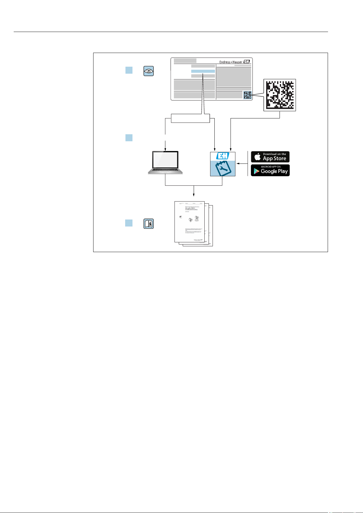
Order code:
Ext. ord. cd.:
Ser. no.:
www.endress.com/deviceviewer
Endress+Hauser
Operations App
XXXXXXXXXXXX
XXXXX-XXXXXX
XXX.XXXX.XX
Serial number
1.
3.
2.
A0023555
• Make sure the document is stored in a safe place such that it is always available when
working on or with the device.
• To avoid danger to individuals or the facility, read the "Basic safety instructions" section
carefully, as well as all other safety instructions in the document that are specific to
working procedures.
• The manufacturer reserves the right to modify technical data without prior notice. Your
Endress+Hauser distributor will supply you with current information and updates to
these Operating Instructions.
2 Endress+Hauser
Page 3

Ceraphant PTC31B, PTP31B, PTP33B IO-Link Table of contents
Table of contents
1 Document information .............. 5
1.1 Document function ..................... 5
1.2 Symbols used .......................... 5
1.3 Documentation ........................ 6
1.4 Terms and abbreviations ................. 7
1.5 Turn down calculation ................... 8
1.6 Registered trademarks ................... 8
2 Basic safety instructions ............ 9
2.1 Requirements concerning the staff .......... 9
2.2 Designated use ........................ 9
2.3 Workplace safety ...................... 10
2.4 Operational safety ..................... 10
2.5 Product safety ........................ 10
3 Product description ................ 11
3.1 Product design ........................ 11
3.2 Function ............................ 11
4 Incoming acceptance and product
identification ..................... 13
4.1 Incoming acceptance ................... 13
4.2 Product identification ................... 14
4.3 Storage and transport .................. 14
8 System integration ................ 31
8.1 Process data ......................... 31
8.2 Reading out and writing device data (ISDU –
Indexed Service Data Unit) ............... 32
8.3 Overview of diagnostic events ............. 34
9 Commissioning .................... 35
9.1 Function check ....................... 35
9.2 Commissioning with an operating menu ..... 35
9.3 Configuring pressure measurement ........ 36
9.4 Performing position adjustment ........... 38
9.5 Configuring process monitoring ........... 40
9.6 Current output ........................ 40
9.7 Application examples ................... 43
10 Diagnostics and troubleshooting ... 44
10.1 Troubleshooting ...................... 44
10.2 Diagnostic events ...................... 45
10.3 Behavior of the device in the event of a fault .. 47
10.4 Signal on alarm 4 to 20 mA .............. 47
10.5 Behavior of the device in the event of a
voltage drop ......................... 48
10.6 Behavior of the device in the event of an
incorrect entry ....................... 48
10.7 Resetting to factory settings (reset) ........ 48
5 Installation ....................... 16
5.1 Mounting dimensions .................. 16
5.2 Installation conditions .................. 16
5.3 Influence of the installation position ........ 16
5.4 Mounting location ..................... 17
5.5 Mounting instructions for oxygen
applications .......................... 19
5.6 Post-installation check .................. 19
6 Electrical connection .............. 20
6.1 Connecting the measuring unit ............ 20
6.2 Switching capacity ..................... 22
6.3 Connection data ....................... 22
6.4 Post-connection check .................. 23
7 Operation options ................. 24
7.1 Operation with an operating menu ......... 24
7.2 Operation with local display .............. 25
7.3 General value adjustment and rejection of
illegal entries ......................... 26
7.4 Navigation and selection from list ......... 26
7.5 Locking and unlocking operation .......... 28
7.6 Navigation examples ................... 30
7.7 Status LEDs .......................... 30
7.8 Resetting to factory settings (reset) ........ 30
11 Maintenance ...................... 48
11.1 Exterior cleaning ...................... 49
12 Repairs ........................... 50
12.1 General notes ........................ 50
12.2 Return .............................. 50
12.3 Disposal ............................ 50
13 Overview of the onsite display
operating menu ................... 51
14 Overview of the IO-Link operating
menu ............................. 54
15 Description of device parameters ... 56
15.1 Observation ......................... 74
16 Accessories ....................... 75
16.1 Weld-in adapter ...................... 75
16.2 Process adapter M24 ................... 75
16.3 M12 plug connectors ................... 76
Endress+Hauser 3
Page 4

Table of contents Ceraphant PTC31B, PTP31B, PTP33B IO-Link
17 Technical data .................... 77
17.1 Input ............................... 77
17.2 Output ............................. 80
17.3 Performance characteristics of ceramic
process isolating diaphragm .............. 83
17.4 Performance characteristics of metal process
isolating diaphragm .................... 85
17.5 Environment ......................... 87
17.6 Process ............................. 88
Index .................................. 90
4 Endress+Hauser
Page 5
Ceraphant PTC31B, PTP31B, PTP33B IO-Link Document information
DANGER
WARNING
CAUTION
NOTICE
1 Document information
1.1 Document function
These Operating Instructions contain all the information that is required in various phases
of the life cycle of the device: from product identification, incoming acceptance and
storage, to mounting, connection, operation and commissioning through to
troubleshooting, maintenance and disposal.
1.2 Symbols used
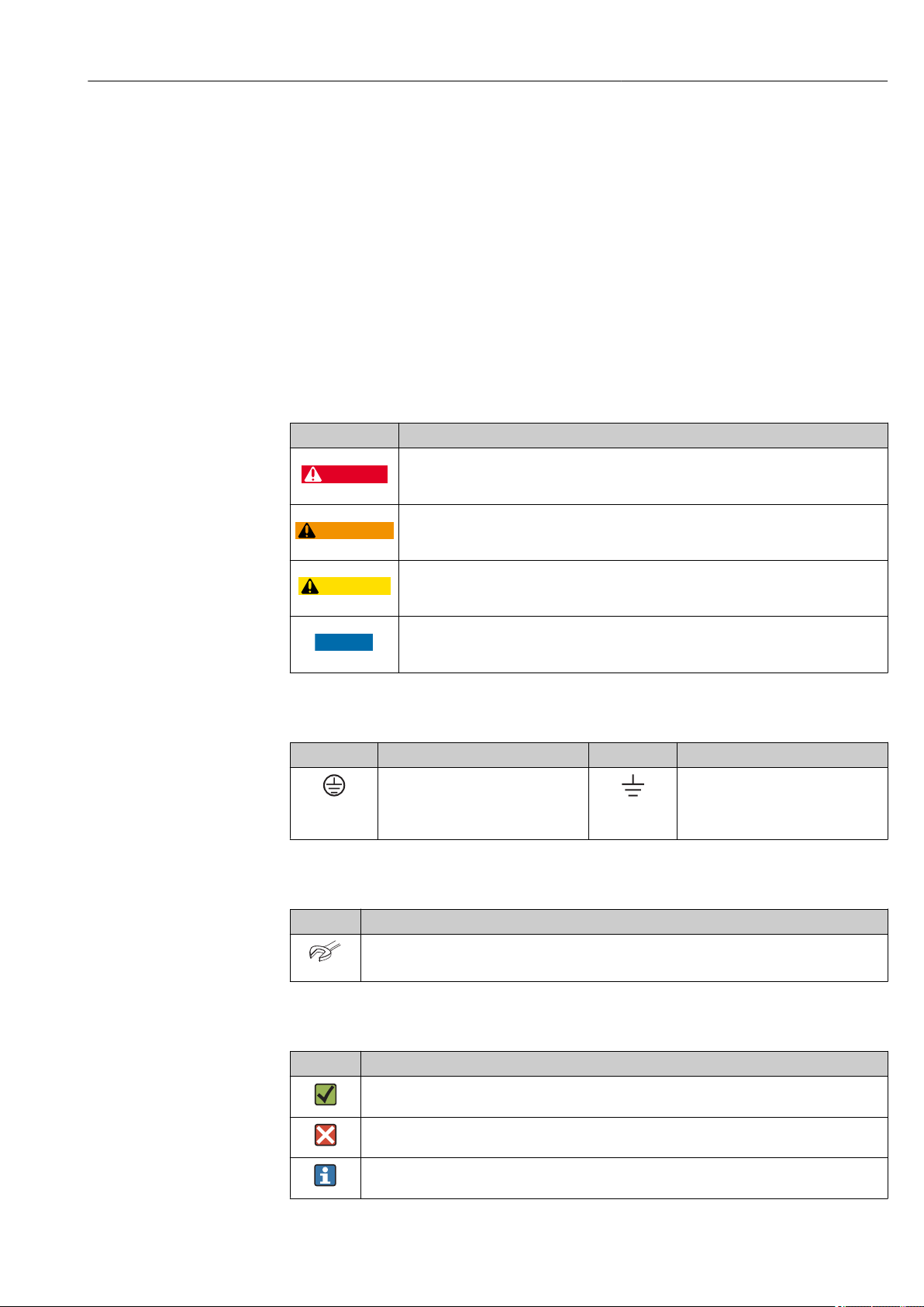
1.2.1 Safety symbols
Symbol Meaning
DANGER!
This symbol alerts you to a dangerous situation. Failure to avoid this situation will result in
serious or fatal injury.
WARNING!
This symbol alerts you to a dangerous situation. Failure to avoid this situation can result in
serious or fatal injury.
CAUTION!
This symbol alerts you to a dangerous situation. Failure to avoid this situation can result in
minor or medium injury.
NOTICE!
This symbol contains information on procedures and other facts which do not result in
personal injury.
1.2.2 Electrical symbols
Symbol Meaning Symbol Meaning
Protective ground connection
A terminal which must be connected
to ground prior to establishing any
other connections.
Ground connection
A grounded terminal which, as far as
the operator is concerned, is
grounded via a grounding system.
1.2.3 Tool symbols
Symbol Meaning
Open-ended wrench
A0011222
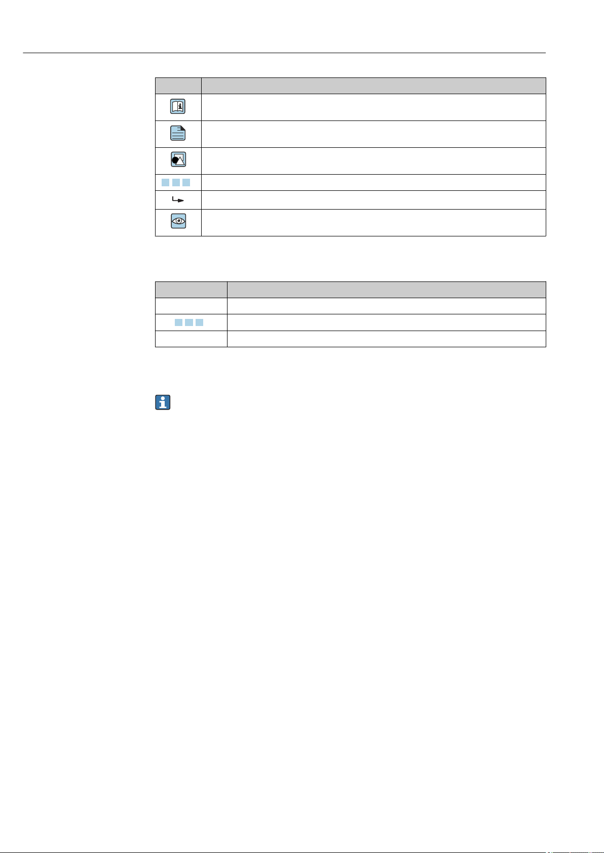
1.2.4 Symbols for certain types of information
Symbol Meaning
Permitted
Procedures, processes or actions that are permitted.
Forbidden
Procedures, processes or actions that are forbidden.
Tip
Indicates additional information.
Endress+Hauser 5
Page 6
Document information Ceraphant PTC31B, PTP31B, PTP33B IO-Link
A
,…,
1.
2.
3.
,…,
1.
2.
3.
Symbol Meaning
Reference to documentation
Reference to page
Reference to graphic
Series of steps
Result of a step
Visual inspection
1.2.5 Symbols in graphics
Symbol Meaning
1, 2, 3 ... Item numbers
Series of steps
A, B, C, ... Views
1.3 Documentation
The document types listed are available:
In the Download Area of the Endress+Hauser Internet site: www.endress.com →
Download
1.3.1 Technical Information (TI): planning aid for your device
PTC31B: TI01130P
PTP31B: TI01130P
PTP33B: TI01246P
The document contains all the technical data on the device and provides an overview of
the accessories and other products that can be ordered for the device.
1.3.2 Brief Operating Instructions (KA): getting the 1st measured value quickly
Devices with IO-Link: KA01404P
These instructions contain all the essential information from incoming acceptance to
initial commissioning.
6 Endress+Hauser
Page 7
Ceraphant PTC31B, PTP31B, PTP33B IO-Link Document information
URL OPLMWP
LRL
0
p
LRV
URV
1
2
3
4
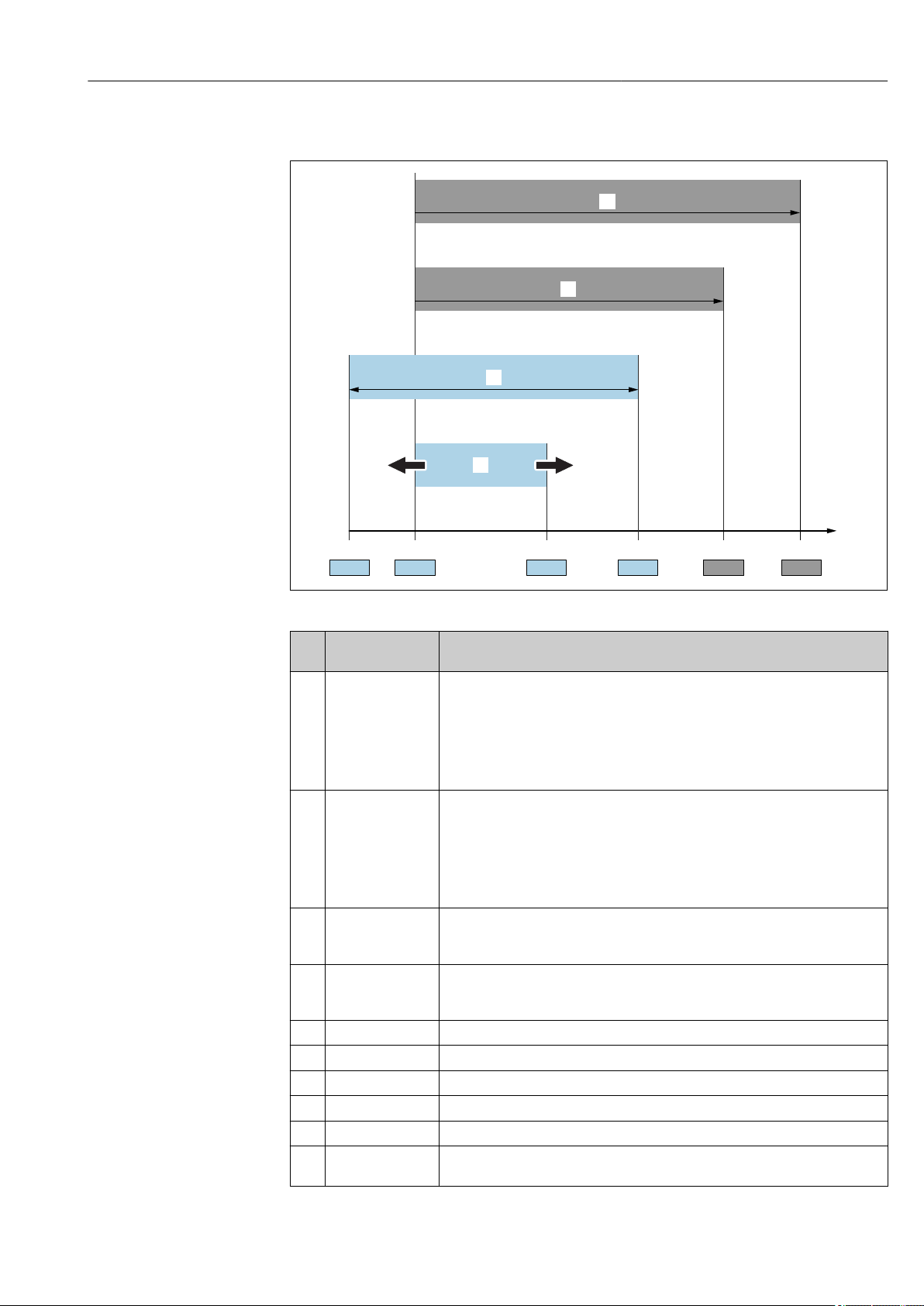
1.4 Terms and abbreviations
A0029505
Item Term/
abbreviation
1 OPL The OPL (over pressure limit = sensor overload limit) for the measuring device
2 MWP The MWP (maximum working pressure) for the sensors depends on the lowest-
3 Maximum sensor
measuring range
4 Calibrated/adjusted
span
p - Pressure
- LRL Lower range limit
- URL Upper range limit
- LRV Lower range value
- URV Upper range value
- TD (turn down) Turn down
Explanation
depends on the lowest-rated element, with regard to pressure, of the selected
components, i.e. the process connection has to be taken into consideration in
addition to the measuring cell. Also observe pressure-temperature dependency. For
the relevant standards and additional notes, see the "Pressure specifications" section
→ 89 .
The OPL may only be applied for a limited period of time.
rated element, with regard to pressure, of the selected components, i.e. the process
connection has to be taken into consideration in addition to the measuring cell.
Also observe pressure-temperature dependency. For the relevant standards and
additional notes, see the "Pressure specifications" section → 89 .
The MWP may be applied at the device for an unlimited period.
The MWP can also be found on the nameplate.
Span between LRL and URL
This sensor measuring range is equivalent to the maximum calibratable/adjustable
span.
Span between LRV and URV
Factory setting: 0 to URL
Other calibrated spans can be ordered as customized spans.
Example - see the following section.
Endress+Hauser 7
Page 8

Document information Ceraphant PTC31B, PTP31B, PTP33B IO-Link
LRV
URLURV
LRL
1 = 2
3
1.5 Turn down calculation
A0029545
1 Calibrated/adjusted span
2 Zero point-based span
3 URL sensor
Example
• Sensor:10 bar (150 psi)
• Upper range value (URL) = 10 bar (150 psi)
Turn down (TD):
• Calibrated/adjusted span: 0 to 5 bar (0 to 75 psi)
• Lower range value (LRV) = 0 bar (0 psi)
• Upper range value (URV) = 5 bar (75 psi)
TD =
|URV - LRV|
TD =
|5 bar (75 psi) - 0 bar (0 psi)|
In this example, the TD is 2:1.
This span is based on the zero point.
URL
10 bar (150 psi)
= 2
1.6 Registered trademarks
is a registered trademark of the IO-Link company group.
8 Endress+Hauser
Page 9

Ceraphant PTC31B, PTP31B, PTP33B IO-Link Basic safety instructions
2 Basic safety instructions
2.1 Requirements concerning the staff
The personnel for installation, commissioning, diagnostics and maintenance must fulfill
the following requirements:
Trained, qualified specialists: must have a relevant qualification for this specific
‣
function and task
Are authorized by the plant owner/operator
‣
Are familiar with federal/national regulations
‣
Before beginning work, the specialist staff must have read and understood the
‣
instructions in the Operating Instructions and supplementary documentation as well as
in the certificates (depending on the application)
Following instructions and basic conditions
‣
The operating personnel must fulfill the following requirements:
Being instructed and authorized according to the requirements of the task by the
‣
facility's owner-operator
Following the instructions in these Operating Instructions
‣
2.2 Designated use
2.2.1 Application and media
The Ceraphant is a pressure switch for measuring and monitoring absolute and gauge
pressure in industrial systems. The process-wetted materials of the measuring device must
have an adequate level of resistance to the media.
The measuring device may be used for the following measurements (process variables)
• in compliance with the limit values specified under "Technical data"
• in compliance with the conditions that are listed in this manual.
Measured process variable
Gauge pressure or absolute pressure
Calculated process variable
Pressure
2.2.2 Incorrect use
The manufacturer is not liable for damage caused by improper or non-designated use.
Verification for borderline cases:
For special fluids and fluids for cleaning, Endress+Hauser is glad to provide assistance
‣
in verifying the corrosion resistance of process-wetted materials, but does not accept
any warranty or liability.
2.2.3 Residual risks
When in operation, the housing may reach a temperature close to the process
temperature.
Danger of burns from contact with surfaces!
For elevated process temperatures, ensure protection against contact to prevent burns.
‣
Endress+Hauser 9
Page 10

Basic safety instructions Ceraphant PTC31B, PTP31B, PTP33B IO-Link
2.3 Workplace safety
For work on and with the device:
Wear the required personal protective equipment according to federal/national
‣
regulations.
Switch off the supply voltage before connecting the device.
‣
2.4 Operational safety
Risk of injury!
Operate the device in proper technical condition and fail-safe condition only.
‣
The operator is responsible for interference-free operation of the device.
‣
Conversions to the device
Unauthorized modifications to the device are not permitted and can lead to unforeseeable
dangers.
If, despite this, modifications are required, consult with Endress+Hauser.
‣
Hazardous area
To eliminate the risk of danger to persons or the facility when the device is used in the
approval-related area (e.g. pressure equipment safety):
Check the nameplate to verify if the device ordered can be put to its intended use in the
‣
approval-related area.
2.5 Product safety
This measuring device is designed in accordance with good engineering practice to meet
state-of-the-art safety requirements, has been tested, and left the factory in a condition in
which it is safe to operate.
It meets general safety standards and legal requirements. It also complies with the EU
directives listed in the device-specific EU Declaration of Conformity. Endress+Hauser
confirms this by affixing the CE mark to the device.
10 Endress+Hauser
Page 11
Ceraphant PTC31B, PTP31B, PTP33B IO-Link Product description
A
B
C
D
E
D
E
D
E
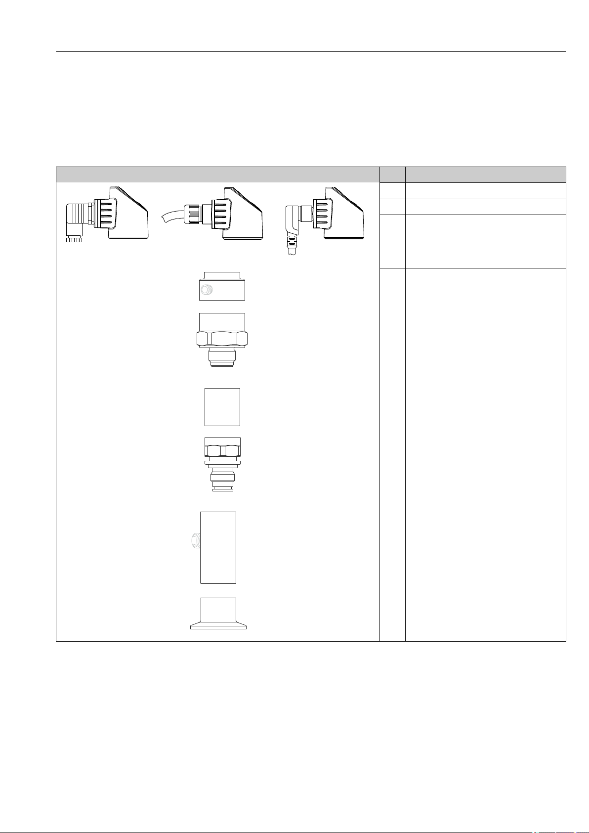
3 Product description
3.1 Product design
Overview Item Description
A Valve plug
B Cable
C M12 plug
Housing cap made of plastic
A0022015
A0037236
A0037238
D
Housing
E
Process connection (sample illustration)
A0027226
A0027215
A0027227
3.2 Function
3.2.1 Calculating the pressure
Endress+Hauser 11
Devices with ceramic process isolating diaphragm (Ceraphire®)
The ceramic sensor is an oil-free sensor, i.e. the process pressure acts directly on the
robust ceramic process isolating diaphragm and causes it to deflect. A pressure-dependent
Page 12

Product description Ceraphant PTC31B, PTP31B, PTP33B IO-Link
change in capacitance is measured at the electrodes of the ceramic substrate and the
process isolating diaphragm. The measuring range is determined by the thickness of the
ceramic process isolating diaphragm.
Devices with metallic process isolating diaphragm
The process pressure deflects the metal process isolating diaphragm of the sensor and a fill
fluid transfers the pressure to a Wheatstone bridge (semiconductor technology). The
pressure-dependent change in the bridge output voltage is measured and evaluated.
12 Endress+Hauser
Page 13
Ceraphant PTC31B, PTP31B, PTP33B IO-Link Incoming acceptance and product identification
DELIVERY NOTE
1 = 2
E
E
DELIVERYNOTE
E
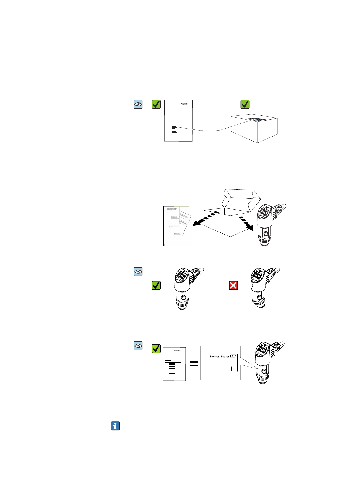
4 Incoming acceptance and product
identification
4.1 Incoming acceptance
A0028673
A0016870
Is the order code on the delivery note (1) identical to the order code on
the product sticker (2)?
A0028673
A0028673
A0022099
A0022101
Are the goods undamaged?
A0022104
Do the data on the nameplate correspond to the order specifications and
the delivery note?
If one of these conditions does not apply, please contact your
Endress+Hauser sales office.
Endress+Hauser 13
Page 14
Incoming acceptance and product identification Ceraphant PTC31B, PTP31B, PTP33B IO-Link
Ser. no.:
Ord. cd.:
Ext. ord. cd.:
D-79689 Maulburg
Made in Germany,
Ceraphant
5
1
2
3
4
Date:
TAG:
4.2 Product identification
The following options are available for the identification of the measuring device:
• Nameplate specifications
• Order code with a breakdown of the device features on the delivery note
• Enter the serial numbers from the nameplates in W@M Device Viewer
(www.endress.com/deviceviewer): All the information about the measuring device is
displayed.
For an overview of the technical documentation provided, enter the serial number from
the nameplates in W@M Device Viewer (www.endress.com/deviceviewer)
4.2.1 Manufacturer address
Endress+Hauser SE+Co. KG
Hauptstraße 1
79689 Maulburg, Germany
Address of the manufacturing plant: See nameplate.
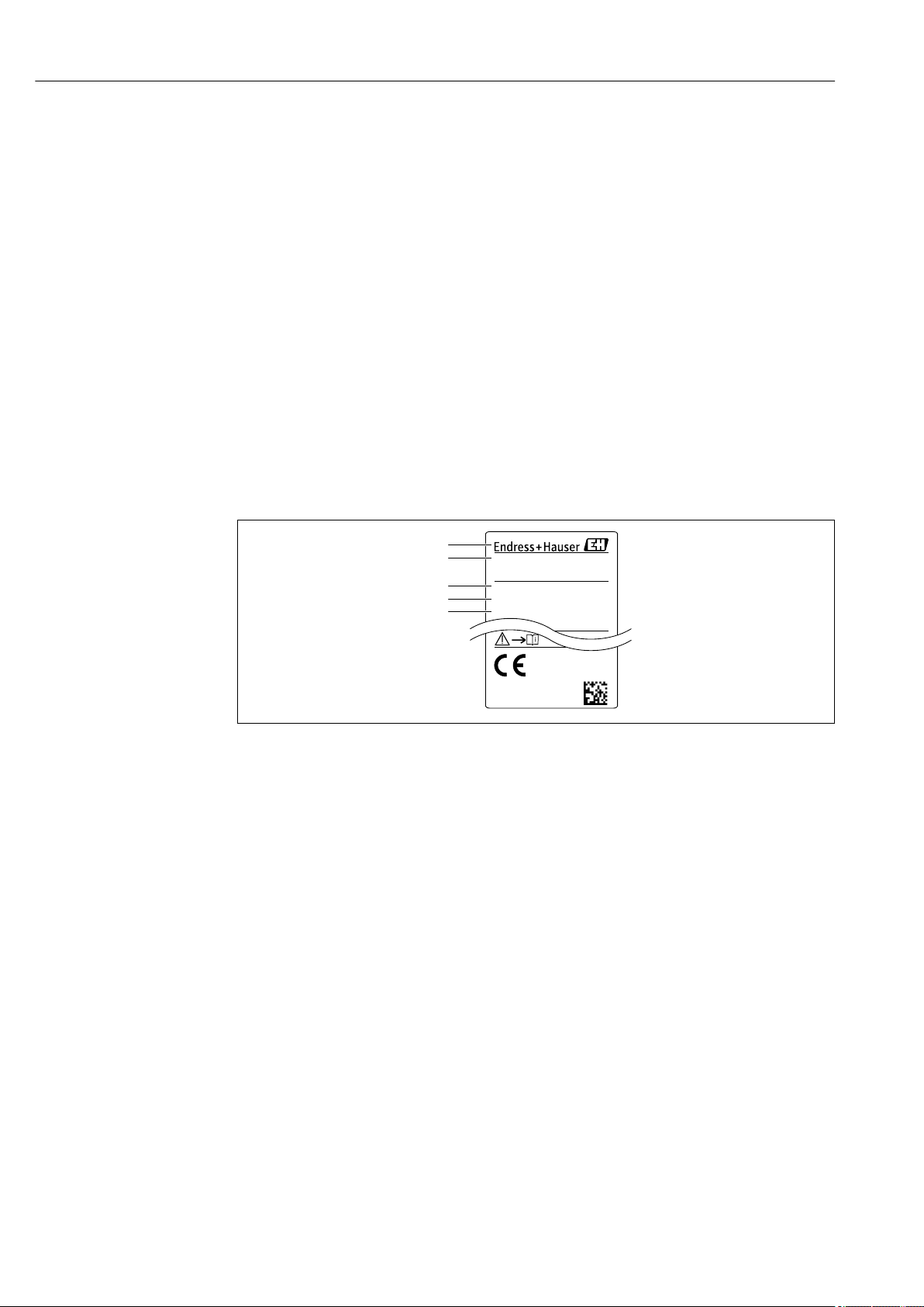
4.2.2 Nameplate
A0030101
1 Manufacturer's address
2 Device name
3 Order number
4 Serial number
5 Extended order number
4.3 Storage and transport
4.3.1 Storage conditions
Use original packaging.
Store the measuring device in clean and dry conditions and protect from damage caused by
shocks (EN 837-2).
Storage temperature range
–40 to +85 °C (–40 to +185 °F)
14 Endress+Hauser
Page 15

Ceraphant PTC31B, PTP31B, PTP33B IO-Link Incoming acceptance and product identification
4.3.2 Transporting the product to the measuring point
WARNING
L
Incorrect transport!
Housing and diaphragm may become damaged, and there is a risk of injury!
Transport the measuring device to the measuring point in its original packaging or by
‣
the process connection.
Endress+Hauser 15
Page 16
Installation Ceraphant PTC31B, PTP31B, PTP33B IO-Link
1
1
1
1
C
A
B
5 Installation
5.1 Mounting dimensions
For dimensions, see the "Mechanical construction" section in the Technical Information.
5.2 Installation conditions
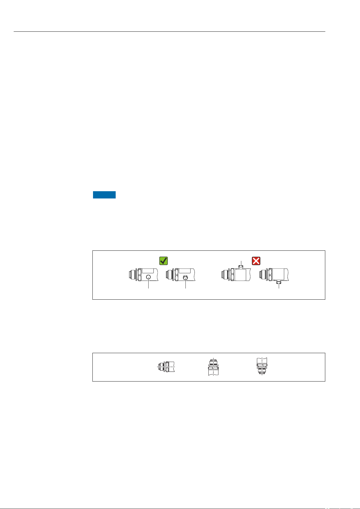
• Moisture must not penetrate the housing when mounting the device, establishing the
electrical connection and during operation.
• Do not clean or touch process isolating diaphragms with hard and/or pointed objects.
• Do not remove process isolating diaphragm protection until shortly before installation.
• Always tighten the cable entry firmly.
• Point the cable and connector downwards where possible to prevent moisture from
entering (e.g. rain or condensation water).
• Protect housing against impact.
• For devices with gauge pressure sensor, the following applies:
NOTICE
If a heated device is cooled in the course of a cleaning process (by cold water, for
example), a vacuum develops for a short time causing moisture to penetrate the
sensor via the pressure compensation element (1).
Device could be destroyed!
In the event of this happening, mount the device in such a way that the pressure
‣
compensation element (1) is pointing downwards at an angle or to the side, if possible.
A0022252
5.3 Influence of the installation position
Any orientation is possible. However, the orientation may cause a zero point shift i.e. the
measured value does not show zero when the vessel is empty or partially full.
A0024708
16 Endress+Hauser
Page 17
Ceraphant PTC31B, PTP31B, PTP33B IO-Link Installation
1
2
Type Process isolating
diaphragm axis is
horizontal (A)
PTP31B
PTP33B
PTC31B
< 1 bar (15 psi)
PTC31B
≥1 bar (15 psi)
Calibration position, no
effect
Calibration position, no
effect
Calibration position, no
effect
Process isolating diaphragm
pointing upwards (B)
Up to +4 mbar (+0.058 psi) Up to –4 mbar (–0.058 psi)
Up to
+0.3 mbar (+0.0044 psi)
Up to +3 mbar (+0.0435 psi) Up to –3 mbar (–0.0435 psi)
Process isolating diaphragm
pointing downwards (C)
Up to
–0.3 mbar (–0.0044 psi)
A position-dependent zero shift can be corrected on the device .
5.4 Mounting location
5.4.1 Pressure measurement
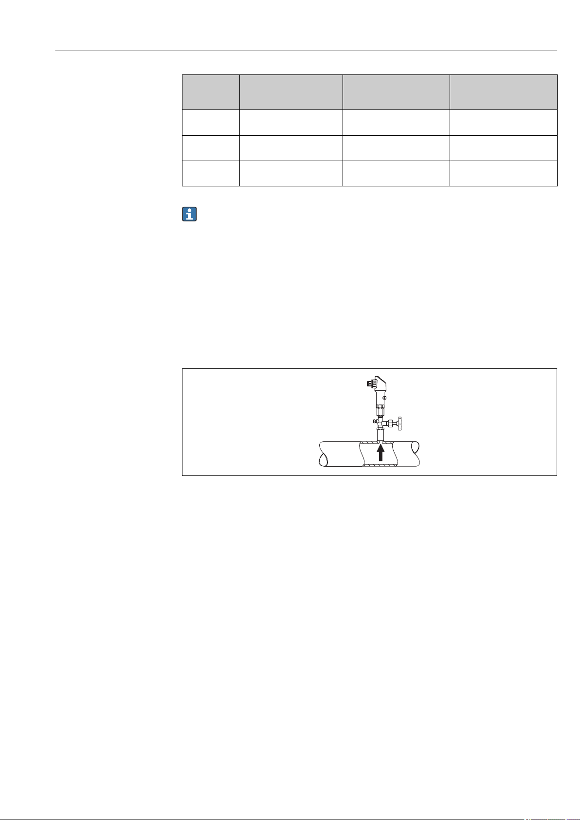
Pressure measurement in gases
Mount the device with shutoff device above the tapping point so that any condensate can
flow into the process.
A0025920
1 Device
2 Shutoff device
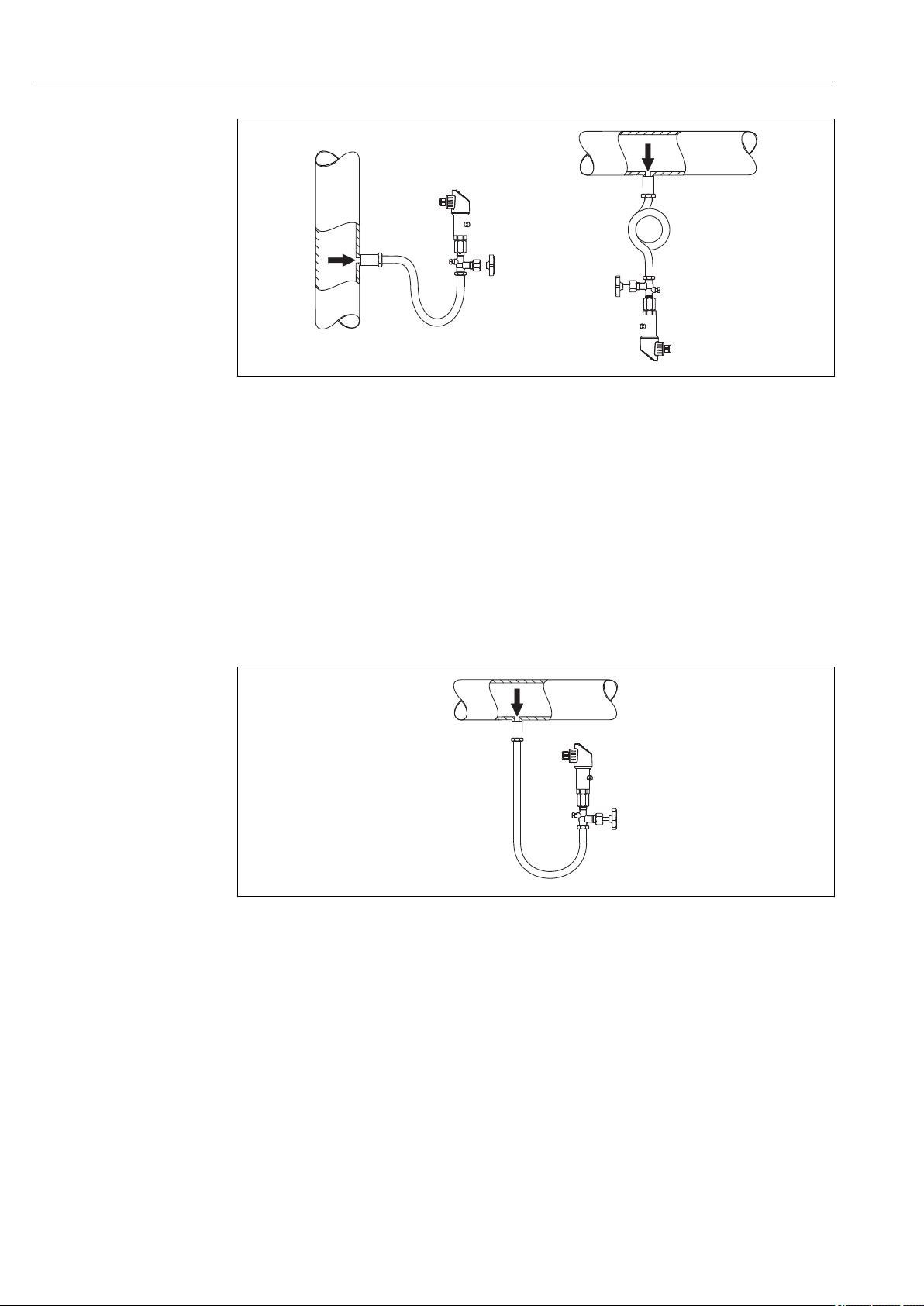
Pressure measurement in vapors
For pressure measurement in vapors, use a siphon. The siphon reduces the temperature to
almost ambient temperature. Preferably mount the device with the shutoff device and
siphon below the tapping point.
Advantage:
• defined water column causes only minor/negligible measuring errors and
• only minor/negligible heat effects on the device.
Mounting above the tapping point is also permitted.
Note the max. permitted ambient temperature of the transmitter!
Take the influence of the hydrostatic water column into consideration.
Endress+Hauser 17
Page 18
Installation Ceraphant PTC31B, PTP31B, PTP33B IO-Link
1
1
2
2
3
4
1
2
3
A0025921
1 Device
2 Shutoff device
3 Siphon
4 Siphon
Pressure measurement in liquids
Mount the device with a shutoff device and siphon below or at the same height as the
tapping point.
Advantage:
• defined water column causes only minor/negligible measuring errors and
• air bubbles can be released to the process.
Take the influence of the hydrostatic water column into consideration.
A0025922
1 Device
2 Shutoff device
3 Siphon
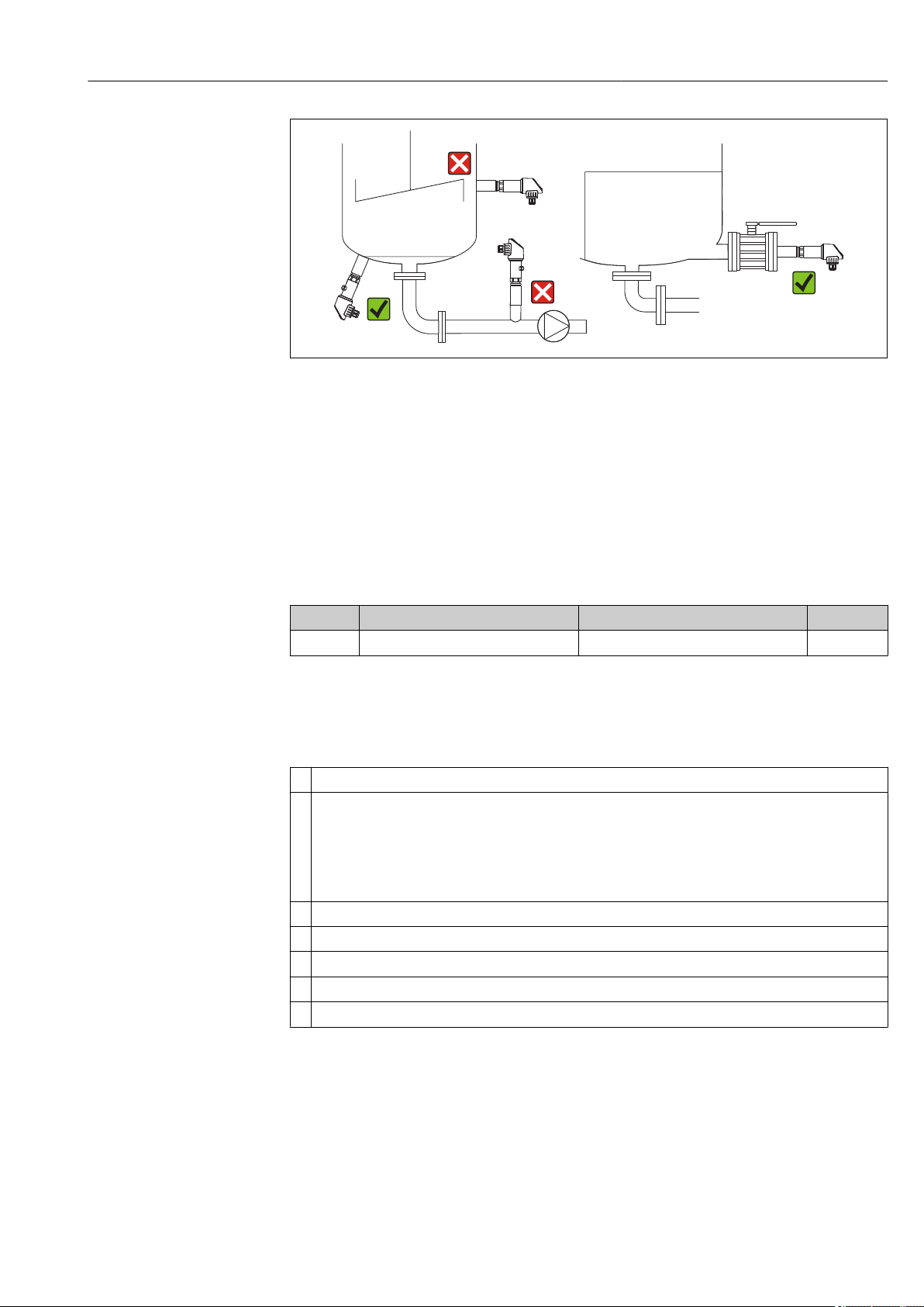
5.4.2 Level measurement
• Always install the device below the lowest measuring point.
• Do not install the device at the following positions:
– In the filling curtain
– In the tank outlet
– in the suction area of a pump
– Or at a point in the tank which could be affected by pressure pulses from the agitator.
18 Endress+Hauser
• A functional test can be carried out more easily if you mount the device downstream
from a shutoff device.
Page 19
Ceraphant PTC31B, PTP31B, PTP33B IO-Link Installation
A0025923
5.5 Mounting instructions for oxygen applications
Oxygen and other gases can react explosively to oils, grease and plastics, such that, among
other things, the following precautions must be taken:
• All components of the system, such as measuring devices, must be cleaned in accordance
with the BAM requirements.
• Dependent on the materials used, a certain maximum temperature and a maximum
pressure for oxygen applications must not be exceeded.
• The following table lists devices (devices only, not accessories or enclosed accessories),
which are suitable for gaseous oxygen applications.
Device p
PTC31B 40 bar (600 psi) –10 to +60 °C (+14 to +140 °F) HB
1) Product Configurator, order code for "Service"
for oxygen applications T
max
for oxygen applications Option
max
5.6 Post-installation check
Is the device undamaged (visual inspection)?
Does the device comply with the measuring point specifications?
For example:
• Process temperature
• Process pressure
• Ambient temperature range
• Measuring range
Are the measuring point identification and labeling correct (visual inspection)?
Is the device adequately protected against precipitation and direct sunlight?
Are the securing screws tightened securely?
Is the pressure compensation element pointing downwards at an angle or to the side?
To prevent moisture from penetrating, ensure that the connecting cables/plugs are pointing downwards.
1)
Endress+Hauser 19
Page 20
Electrical connection Ceraphant PTC31B, PTP31B, PTP33B IO-Link
L–
L+
0.63A
2
1
3
4
R1
R1
"
L–
L+
1
2
3
4
0.63A
L–
L+
1
2a
3
4
2b
R1
"
(a)
0.63A
6 Electrical connection
6.1 Connecting the measuring unit
6.1.1 Terminal assignment
WARNING
L
Risk of injury from the uncontrolled activation of processes!
Switch off the supply voltage before connecting the device.
‣
Make sure that downstream processes are not started unintentionally.
‣
WARNING
L
Electrical safety is compromised by an incorrect connection!
In accordance with IEC/EN61010 a separate circuit breaker must be provided for the
‣
device .
The device must be operated with a 630 mA fine-wire fuse (slow-blow).
‣
Protective circuits against reverse polarity are integrated.
‣
NOTICE
Damage to analog input of PLC resulting from incorrect connection
Do not connect the active PNP switch output of the device to the 4 to 20 mA input of a
‣
PLC.
Connect the device in the following order:
1. Check that the supply voltage corresponds to the supply voltage indicated on the
nameplate.
2. Connect the device in accordance with the following diagram.
Switch on supply voltage.
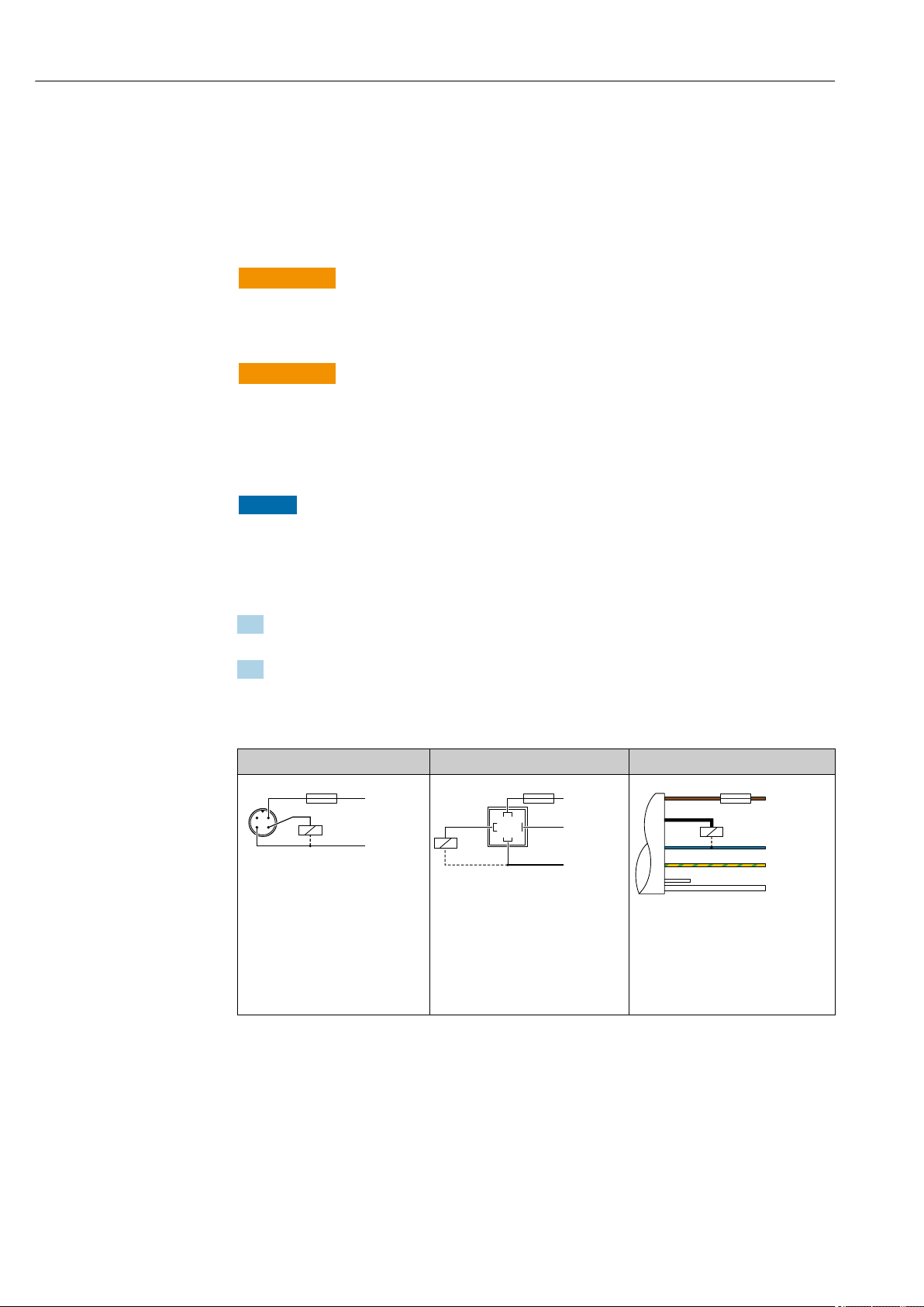
1 x PNP switch output R1 (not with IO-Link functionality)
M12 plug Valve plug Cable
A0029268
A0023271
1 brown = L+
2a black = switch output 1
2b white = not in use
3 blue = L4 green/yellow = ground
(a) reference air hose
A0022801
20 Endress+Hauser
Page 21
Ceraphant PTC31B, PTP31B, PTP33B IO-Link Electrical connection
L–
L+
2
1
3
4
R1
R2
0.63A
L–
L+
1
2b
2a
3
4
R2
(a)
0.63A
R1
"
L–
L+
C/Q1
2
1
3
4
SIO
IO-Link
0.63 A
R1
Q2
L–
L+
2
1
3
4
R1
0.63A
L–
L+
1
2b
2a
3
4
(a)
0.63A
R1
"
0.63 A
C/Q
L–
L+
2
1
3
4
SIO
IO-Link
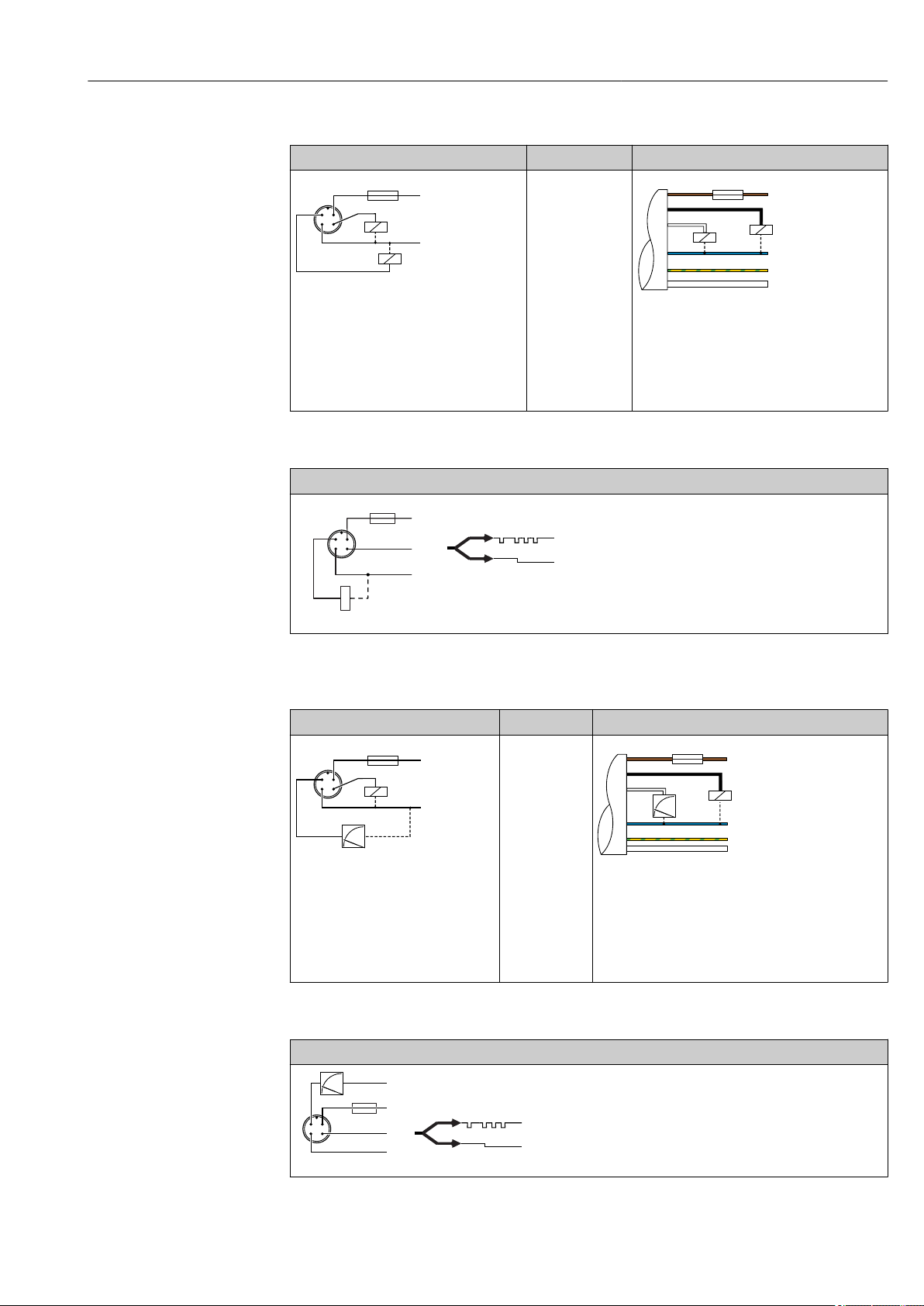
2 x PNP switch output R1 and R2 (not with IO-Link functionality)
M12 plug Valve plug Cable
-
A0023248
A0023282
1 brown = L+
2a black = switch output 1
2b white = switch output 2
3 blue = L4 green/yellow = ground
(a) reference air hose
IO-Link: 2 x PNP switch output R1 and R2
M12 plug
A0036997
1 x PNP switch output R1 with additional analog output 4 to 20 mA (active), (not with IOLink functionality)
M12 plug Valve plug Cable
-
A0023249
1 brown = L+
2a black = switch output 1
2b white = analog output 4 to 20 mA
3 blue = L4 green/yellow = ground
(a) reference air hose
A0030519
IO-Link: 1 x PNP switch output R1 with additional analog output 4 to 20 mA (active)
M12 plug
A0036998
Endress+Hauser 21
Page 22

Electrical connection Ceraphant PTC31B, PTP31B, PTP33B IO-Link
6.1.2 Supply voltage
Supply voltage IO-Link: 10 to 30 V DC at a DC power unit
IO-Link communication is guaranteed only if the supply voltage is at least 18 V.
6.1.3 Current consumption and alarm signal
Intrinsic power consumption Alarm current (for devices with analog output)
≤ 60 mA ≥21 mA (factory setting)
Maximum current consumption: ≤ 300 mA
1) Setting min. alarm current ≤3.6mA can be ordered via the product order structure. Min. alarm current
≤3.6mA can be configured at the device or via IO-Link.
1)
6.2 Switching capacity
• Switch state ON
1)
: Ia ≤ 200 mA
• Switch cycles: >10,000,000
• Voltage drop PNP: ≤2 V
• Overload protection: Automatic load testing of switching current;
– Max. capacitive load: 1 μF at max. supply voltage (without resistive load)
– Max. cycle duration: 0.5 s; min. ton: 40 μs
– Periodic disconnection from protective circuit in the event of overcurrent (f = 2 Hz) and
"F804" displayed
2)
; switch state OFF: Ia ≤100 μA
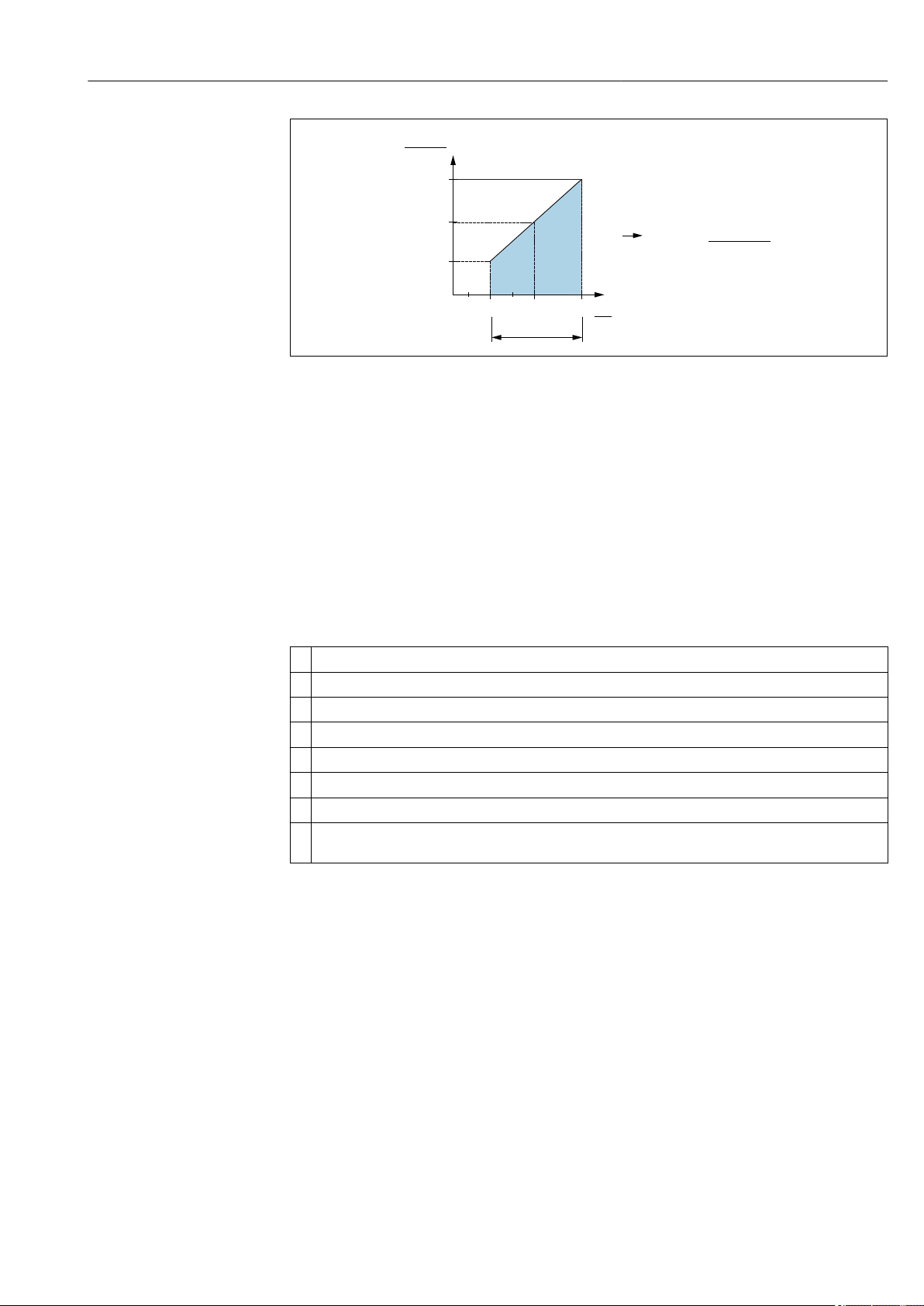
6.3 Connection data
6.3.1 Load (for devices with analog output)
In order to guarantee sufficient terminal voltage, a maximum load resistance RL (including
line resistance) must not be exceeded depending on the supply voltage UB of the supply
unit.
The maximum load resistance depends on the terminal voltage and is calculated according
to the following formula:
1) 100 mA can be guaranteed over the entire temperature range for the switch outputs "2 x PNP" and "1 x PNP + 4 to 20 mA output". For lower
ambient temperatures, higher currents are possible but cannot be guaranteed. Typical value at 20 °C (68 °F) approx. 200 mA. 200 mA can be
guaranteed over the entire temperature range for the "1 x PNP" current output.
2) Larger currents are supported, thus deviating from the IO-Link standard.
22 Endress+Hauser
Page 23
Ceraphant PTC31B, PTP31B, PTP33B IO-Link Electrical connection
[ ]W
20 30
10
0
1022
587
152
U
[V]
1
2
R
R
L
L
max
max
£
-U 6.5V
23mA
B
B
A0031107
1 Power supply 10 to 30 V DC
2 R
UBSupply voltage
maximum load resistance
Lmax
If load is too great:
• failure current is output and "S803" displayed (output: MIN alarm current)
• Periodic checking to establish if it is possible to quit fault state
• In order to guarantee sufficient terminal voltage, a maximum load resistance RL
(including line resistance) must not be exceeded depending on the supply voltage UB of
the supply unit.
6.4 Post-connection check
Is the device or cable undamaged (visual check)?
Do the cables comply with the requirements?
Do the cables have adequate strain relief?
Are all the cable glands installed, firmly tightened and leak-tight?
Does the supply voltage match the specifications on the nameplate?
Is the terminal assignment correct?
If required: has protective ground connection been established?
If supply voltage is present: is the device ready for operation and do values appear on the display module or
is the green status LED lit?
Endress+Hauser 23
Page 24

Operation options Ceraphant PTC31B, PTP31B, PTP33B IO-Link
7 Operation options
7.1 Operation with an operating menu
7.1.1 IO-Link
IO-Link information
IO-Link is a point-to-point connection for communication between the measuring device
and an IO-Link master. The measuring device features an IO-Link communication interface
type 2 with a second IO function on pin 4. This requires an IO-Link-compatible assembly
(IO-Link master) for operation. The IO-Link communication interface enables direct access
to the process and diagnostic data. It also provides the option of configuring the measuring
device on the fly.
Physical layer, the measuring device supports the following features:
• IO-Link specification: version 1.1
• IO-Link Smart Sensor Profile 2nd Edition (supports minimum scope of IdentClass)
• SIO mode: yes
• Speed: COM2; 38.4 kBaud
• Minimum cycle time: 2.5 msec.
• Process data width: 32 bit
• IO-Link data storage: yes
• Block parameterization: yes
IO-Link download
http://www.endress.com/download
• Select "Software" as the media type.
• Select "Device Driver" as the software type.
Select IO-Link (IODD).
• In the "Text Search" field enter the device name.
https://ioddfinder.io-link.com/
Search by
– Manufacturer
– Article number
– Product type
7.1.2 Operating concept
Operation with an operating menu is based on an operation concept with "user roles" .
User role Meaning
Operator
(display level)
Maintenance
(user level)
Operators are responsible for the devices during normal "operation". This is usually limited to
reading process values either directly at the device or in a control room. Should an error occur,
these users simply forward the information on the errors but do not intervene themselves.
Service engineers usually work with the devices in the phases following device commissioning.
They are primarily involved in maintenance and troubleshooting activities for which simple
settings have to be made on the device. Technicians work with the devices over the entire life
cycle of the product. Thus, commissioning and advanced settings and configurations are some
of the tasks they have to carry out.
24 Endress+Hauser
Page 25
Ceraphant PTC31B, PTP31B, PTP33B IO-Link Operation options
2
E
54
3
1
7.1.3 Structure of the operating menu
The menu structure has been implemented according to VDMA 24574-1 and
complemented by Endress+Hauser-specific menu items.
User role Submenu Meaning/use
Operator (display
level)
Maintenance (user
level)
For an overview of the operating menu, see → 51 and → 54
Display/operat. Display of measured values, fault and information messages
Parameters on
the topmost
menu level.
EF The submenu "EF" (Extended Functions) contains additional
DIAG Contains all the parameters that are needed to detect and analyze
Contains all the parameters that are needed to commission
measuring operations. A wide range of parameters, which can be
used to configure a typical application, is available at the start. After
making settings for all these parameters, the measuring operation
should be completely configured in the majority of cases.
parameters which allow more accurate configuration of the
measurement, conversion of the measured value and scaling of the
output signal.
operating errors.
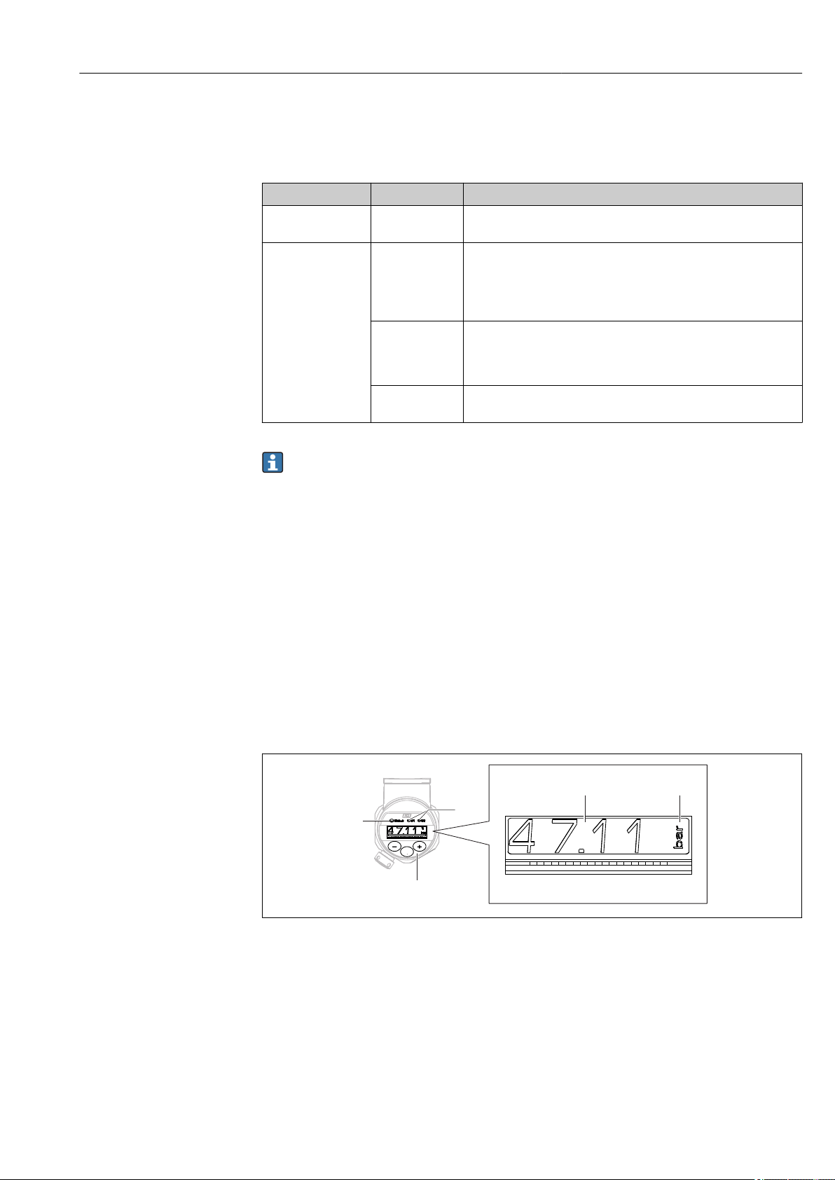
7.2 Operation with local display
7.2.1 Overview
A 1-line liquid crystal display (LCD) is used for display and operation. The local display
shows measured values, fault messages and information messages and therefore supports
the user through each operating step.
The display is fixed to the housing and can be electronically rotated 180° (see parameter
description for "DRO" → 73). This ensures optimum readability of the local display and
allows the device to be mounted upside down also.
During measuring operation, the display shows measured values, fault messages and
notice messages. In addition, it is possible to switch to menu mode via the operating keys.
A0022121
1 Operating keys
2 Status LED
3 Switch output LEDs
4 Measured value
5 Unit
The second switch output is not used for the device version with current output.
Endress+Hauser 25
Page 26
Operation options Ceraphant PTC31B, PTP31B, PTP33B IO-Link
7.2.2 Information on the operational states
Operational states Function of status-LED and onsite display
Operation • Status LED is lit green
• LEDs of switch output 1 and switch output 2 signal the status of each switch output
• No activity of LED for switch output 2 if current output is active
• White background lighting
Problem • Status LED lit steady red
• Red display background
• LED of switch output 1 and switch output 2 off (switch output is deactivated)
Warning • Status LED flashing red
• White display background
• LEDs of switch output 1 and switch output 2 signal the status of each switch output
For Device Search • The green LED is lit (= operational) on the device and starts to flash with increased
luminosity. Flash frequency
• LEDs of switch output 1 and switch output 2 signal the status of each switch output
• Display background depending on the device status
IO-Link
communication
• Status LED flashes green as per IO-Link specification (regardless of measuring
operation, error or warning). Flash frequency
• Display background depending on the device status
• The state of switch output 1 is also indicated via the LED of switch output 1 at the same
time as the process data are displayed
7.3 General value adjustment and rejection of illegal entries
Parameter (not numerical value) is flashing: parameter can be adjusted or selected.
When adjusting a numerical value: the numerical value does not flash. The first digit of the
numerical value starts to flash only when the key is pressed by way of confirmation.
Enter the desired value with the or key and press the key to confirm. Following
confirmation, the data are recorded directly and are active.
– Entry is OK: value is accepted and shown for one second on the display against a white
background.
– Entry is not OK: the message "FAIL" appears for one second on the display against a red
background. The value entered is rejected. In the event of an incorrect setting which
affects the TD, an diagnostic message is displayed.
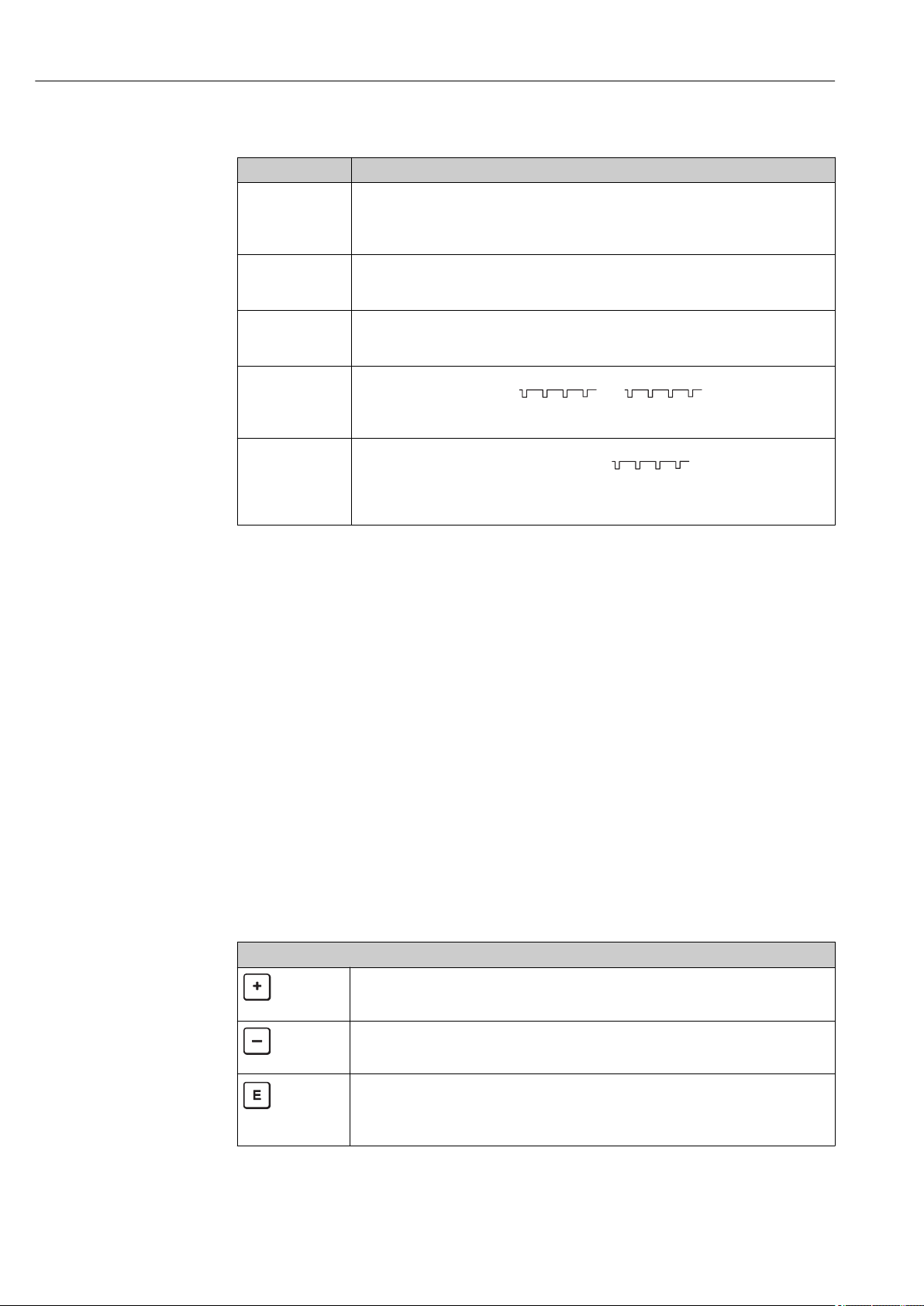
7.4 Navigation and selection from list
The capacitive operating keys are used for navigation in the operating menu and to select
an option from a picklist.
Operating key(s) Meaning
• Navigate downwards in the picklist
A0017879
A0017880
A0017881
• Edit the numerical values or characters within a function
• Navigate upwards in the picklist
• Edit the numerical values or characters within a function
• Confirm entry
• Jump to the next item
• Select a menu item and activate the edit mode
• The key lock function (KYL) is accessed by pressing the key for longer than 2 seconds
26 Endress+Hauser
Page 27

Ceraphant PTC31B, PTP31B, PTP33B IO-Link Operation options
Operating key(s) Meaning
Simultaneously ESC functions:
• Exit edit mode for a parameter without saving the changed value.
• You are in a menu at a selection level. Each time you press the keys simultaneously, you
A0017880
go up a level in the menu.
• Long ESC: press the keys for longer than 2 seconds
A0017879
and
Endress+Hauser 27
Page 28

Operation options Ceraphant PTC31B, PTP31B, PTP33B IO-Link
7.5 Locking and unlocking operation
The device features
• Automatic key locking
• Parameter settings lock.
Key locking is indicated on the local display by "E > 2".
Locking of the parameter settings is indicated as soon as an attempt is made to change a
parameter.
7.5.1 Disabling the key lock
The keys are locked automatically if the device remains at the topmost menu level (display
of pressure measurement value) for 60 seconds.
Call up the key lock function (KYL)
1. Press the key for at least 2 seconds and then release it
2. By confirming with "ON" is displayed
3. Use and to toggle between "ON" and "OFF"
4. Key locking is disabled as soon as is pressed to confirm "OFF"
The display changes to the main value level (topmost menu level) if the key is pressed
briefly. The display changes to the key locking if the key is pressed for at least 2
seconds.
If in the case of "KYL", "ON" or "OFF", more than 10 seconds elapse without a key being
pressed, you return to the topmost menu level with active key locking.
The function can be accessed anytime outside the main measured value display and within
the operating menu, i.e. if the key is pressed for at least 2 seconds key locking can be
performed anytime at any menu item. Locking is effective immediately. If you quit the
context menu, you will return to the same point from which key locking was selected.
7.5.2 Locking and unlocking parameter settings
The device settings can be protected from unauthorized access.
COD parameter: define the locking code
0000 Device is permanently unlocked (factory setting)
0001-9999 Device is locked
LCK parameter: unlock parameter locking (enter the COD)
If parameters are locked, the word "LCK" appears on the local display as soon as an attempt
is made to change a parameter.
Examples:
Locking the device with a customer-specific code
1. EF → ADM → COD
2. Enter a COD not equal to 0000 (value range: 0001 to 9999)
3. Wait 60 seconds or restart the device
4. Parameters are locked (protected against changes)
Changing a parameter when the device is locked (taking the example of STL)
1. STL, LCK is displayed
28 Endress+Hauser
Page 29

Ceraphant PTC31B, PTP31B, PTP33B IO-Link Operation options
2. Enter the customer-specific value defined in COD
3. STL can be edited
4. The device is locked again after 60 seconds or following a restart
Unlocking the locking mechanism permanently
1. EF → ADM → COD
2. LCK is displayed, enter the customer-specific value defined in COD
3. Enter "0000"
4. The device is unlocked (even after the device is restarted)
Endress+Hauser 29
Page 30

Operation options Ceraphant PTC31B, PTP31B, PTP33B IO-Link
1
E
2
7.6 Navigation examples
7.6.1 Parameters with a picklist
Example: Display measured value rotated by 180°
Menu path: EF → DIS → DRO
Press or key until "DRO" is displayed.
The default setting is "NO" (display is not rotated).
Press or until "YES" appears (display is rotated by 180°).
Press to confirm the setting.
7.6.2 User-definable parameters
Example: setting the "TAU" damping parameter.
Menu path: EF → TAU
Press or key until "TAU" is displayed.
Press to set the damping (min. = 0.0 s; max.= 999.9 s).
Press or to go up or down.
Press to confirm the entry and to go to the next position.
Press to quit the setting function and to go to the "TAU" menu item.
D R O
N O
Y E S
D R O
T A U
0. 3 0
1. 5
T A U
7.7 Status LEDs
The Ceraphant also uses LEDs to signal the status:
• Two LEDs indicate the status of the switch outputs (switch output 2 can optionally be
used as a current output)
• One LED indicates if the device is switched on or if an error or fault has occurred
1 Status LED
2 Switch output LEDs
7.8 Resetting to factory settings (reset)
See parameter description for RES → 71
30 Endress+Hauser
A0032027
Page 31

Ceraphant PTC31B, PTP31B, PTP33B IO-Link System integration
8 System integration
8.1 Process data
The measuring device has one current output and one or two switch outputs (depending
on the version ordered). The status of the switch outputs and the pressure value are
transmitted in the form of process data via IO-Link.
• In the SIO mode, the switch output is switched at pin 4 of the M12 plug. In the IO-Link
communication mode, this pin is reserved exclusively for communication.
• If the "with current output" option is ordered, the current output at pin 2 of the M12 plug
is always active or can optionally be deactivated via IO-Link or at the display or
configured as DC-PMP.
• The device's process data are transmitted cyclically in 32-bit chunks.
Bit 0 (LSB) 1 ... 28 29 (MSB) 30 31
Measuring device Pressure value OU1 OU2
Bit 30 and bit 31 indicate the state of the switch outputs.
Here, 1 or DC 24 V corresponds to the logical "closed" state on the switch output. The
remaining 30 bits contain the analog raw measured value of the device. This value has yet
to be scaled by the target system to the nominal operating range of the existing measuring
device.
Bit Process value Value range
31 OU1 0 = open
1 = closed
30 OU2 0 = open
1 = closed
0 to 29 Raw value Integer
The pressure value is provided by the measuring device as int30. The decimal separator
must be set with a gradient. The number of decimal places displayed is based on the
display format of the device. The gradients depend on the unit in question. The following
units are available:
• bar: 0.0001
• kPa: 0.01
• MPa: 0.00001
• psi: 0.001
Examples:
Pressure value Transmitted Scaled with gradient
-320 mbar -3200 -0.32
22 bar 220000 22
133 kPa 13300 133
665 psi 665000 665
399.5 bar 3995000 399.5
Endress+Hauser 31
Page 32

System integration Ceraphant PTC31B, PTP31B, PTP33B IO-Link
8.2 Reading out and writing device data (ISDU – Indexed Service Data Unit)
Device data are always exchanged acyclically and at the request of the IO-Link master.
Using the device data, the following parameter values or device statuses can be read out:
8.2.1 Endress+Hauser-specific device data
Designation ISDU
(dec)
Extended Ordercode 259 0x0103 60 String r/-
ENP_VERSION 257 0x0101 16 String r/- 36587
Device Type 256 0x0100 2 Uinteger16 r/- 0x92FE
Simulation Switch Output
(OU1)
Simulation Current Output
(OU2)
Simulation switch output
(OU2)
Device search 87 0x0057 1 uint r/w Off 0 ~ off
Operating Mode (FUNC) 88 0x0058 1 uint r/w 1 0 ~ off,
Unit changeover (UNI) 67 0x0043 1 uint r/w 0 ~ bar,
Zero point configuration
(ZRO)
Zero point adoption (GTZ) 69 0x0045 1 uint -/w No
Damping (TAU) 70 0x0046 2 uint r/w 20 in 000.0 sec, default
Lower Range Value for 4
mA (STL)
Upper Range Value for 20
mA (STU)
Pressure applied for 4mA
(GTL)
Pressure applied for 20mA
(GTU)
Alarm current (FCU) 75 0x004B 1 uint r/w MAX 0 ~ MIN,
85 0x0055 r/w Off 0 ~ off,
66 0x0042 1 uint r/w Off 4 ~ 4 mA,
86 0x0056 1 uint r/w Off 0 ~ off,
68 0x0044 4 int r/w 0 in 00.00%, default
71 0x0047 4 int r/w 0 in 00.00%, default
72 0x0048 4 int r/w 10000 in 00.00%, default
73 0x0049 1 uint -/w No
74 0x004A 1 uint -/w No
ISDU
(hex)
Size
(byte)
Data type Access Default
value
Value range Offset /
Gradient
1 ~ low,
2 ~ high,
5 ~ 8 mA,
6 ~ 12 mA,
7 ~16 mA,
8 ~ 20 mA,
9 ~ 21.95 mA,
otherwise 3.5 mA
1 ~ low,
2 ~ high
1 ~ on
1 ~ I,
2 ~ PNP
1 ~ kPa,
2~ psi,
3~ MPa
0.00%
0 / 0.1 Yes
2.0 sec
bar: 0 / 0.001
0.00%
100.00%
1 ~ MAX,
2~ HOLD
kPa: 0 / 0.1
MPa: 0 /
0.0001
psi: 0 / 0.01
bar: 0 / 0.001
kPa: 0 / 0.1
MPa: 0 /
0.0001
psi: 0 / 0.01
Data
storage
No
No
No
Yes
Yes
Yes
Yes
Yes
Yes
32 Endress+Hauser
Page 33

Ceraphant PTC31B, PTP31B, PTP33B IO-Link System integration
Designation ISDU
(dec)
Switch point value / Upper
77 0x004D 4 int r/w 9000 in 00.00%, default
value for pressure window,
output 1 (SP1 / FH1)
ISDU
(hex)
Size
(byte)
Data type Access Default
value
Value range Offset /
Gradient
bar: 0 / 0.001
90.00%
kPa: 0 / 0.1
MPa: 0 /
Data
storage
Yes
0.0001
psi: 0 / 0.01
Switchback point value /
Lower value for pressure
window, output 1 (rP1 /
FL1)
78 0x004E 4 int r/w 1000 in 00.00%, default
10.00%
bar: 0 / 0.001
kPa: 0 / 0.1
MPa: 0 /
0.0001
Yes
psi: 0 / 0.01
Switching delay time, output
79 0x004F 2 uint r/w 0 in 00.00 sec 0 / 0.01 Yes
1 (dS1)
Switchback delay time,
80 0x0050 2 uint r/w 0 in 00.00 sec 0 / 0.01 Yes
output 1 (dR1)
1 ~ HNC
2 ~ FNO
3 ~ FNC
95.00%
1)
,
1)
,
1)
,
1)
bar: 0 / 0.001
Yes
Yes
kPa: 0 / 0.1
MPa: 0 /
Output 1 (OU1) 81 0x0051 1 uint r/w HNO 0 ~ HNO
Switch point value / Upper
89 0x0059 4 int r/w 9500 in 00.00%, default
value for pressure window,
output 2 (SP2 / FH2)
0.0001
psi: 0 / 0.01
Switchback point value /
Lower value for pressure
window, output 2 (rP2 /
FL2)
90 0x005A 4 int r/w 1500 in 00.00%, default
15.00%
bar: 0 / 0.001
kPa: 0 / 0.1
MPa: 0 /
0.0001
Yes
psi: 0 / 0.01
Switching delay time, output
91 0x005B 2 uint r/w 0 in 00.00 sec 0 / 0.01 Yes
2 (dS2)
Switchback delay time,
92 0x005C 2 uint r/w 0 in 00.00 sec 0 / 0.01 Yes
output 2 (dR2)
1 ~ HNC
2 ~ FNO
3 ~ FNC
1)
,
1)
,
1)
,
1)
Yes
Output 2 (OU2) 93 0x005D 1 uint r/w HNC 0 ~ HNO
Hi Max value (maximum
82 0x0052 4 int r/- No
indicator)
Lo Min value (minimum
83 0x0053 4 int r/- No
indicator)
Revisioncounter (RVC) 84 0x0054 2 uint r/- No
unlocking code (LCK) 94 0x005E 2 uint -/w 0 Yes
locking code (COD) 95 0x005F 2 uint -/w 0 Yes
Measured value display
(DVA)
96 0x0060 1 uint r/w 0 0~ PV for device with
non-active current
Yes
output
1~ PV% only for
devices with active
current output
2~display set switch
point SP
Display measured value
rotated by 180° (DRO)
Switch display on or off
(DOF)
97 0x0061 1 uint r/w NO 0 ~ NO,
1 ~ YES
98 0x0062 1 uint r/w NO 0 ~ NO,
1 ~ YES
Yes
Yes
1) For an explanation of the abbreviations, see the parameter description → 70
Endress+Hauser 33
Page 34

System integration Ceraphant PTC31B, PTP31B, PTP33B IO-Link
8.2.2 IO-Link-specific device data
Designation ISDU (dec) ISDU (hex) Size (byte) Data type Access Default value
Serial number 21 0x0015 max. 16 String r/-
Firmware version 23 0x0017 max. 64 String r/-
ProductID 19 0x0013 max. 64 String r/- PTx3xB
ProductName 18 0x0012 max. 64 String r/- Ceraphant
ProductText 20 0x0014 max. 64 String r/- Absolute and gauge pressure
VendorName 16 0x0010 max. 64 String r/- Endress+Hauser
VendorId 7 to 8 0x0007 to 0x0008 r/- 17
VendorText 17 0x0011 max. 64 String r/- People for Process Automation
DeviceId 9 to 11 0x0009 to 0x000B r/- 0x000700
Hardware revision 22 0x0016 max. 64 String r/-
Application Specific Tag 24 0x0018 32 String r/w
Actual Diagnostics (STA) 260 0x0104 4 String r/-
Last Diagnostic (LST) 261 0x0105 4 String r/-
8.2.3 System commands
Designation ISDU (dec) ISDU (hex) Value range Access
Reset to factory settings (RES) 130 0x0082 w
Device Access Locks.Data Storage Lock 12 0x000C 0 ~ False
2 ~ True
Device Access Locks.Local Parametrization Lock 130 w
rw
8.3 Overview of diagnostic events
→ 45
34 Endress+Hauser
Page 35

Ceraphant PTC31B, PTP31B, PTP33B IO-Link Commissioning
9 Commissioning
If an existing configuration is changed, measuring operation continues! The new or
modified entries are only accepted once the setting has been made.
If block parameterization is used, a parameter change is only adopted after the parameter
download.
WARNING
L
Risk of injury from the uncontrolled activation of processes!
Make sure that downstream processes are not started unintentionally.
‣
WARNING
L
If a pressure smaller than the minimum permitted pressure or greater than the
maximum permitted pressure is present at the device, the following messages are
output in succession:
S140
‣
F270
‣
NOTICE
An IO-DD with corresponding default values is used for all pressure measuring
ranges. This IO-DD applies for all measuring ranges! The default values of this IO-DD
can be inadmissible for this device. IO-Link messages (e.g. "Parameter value above
limit") may be displayed when the device is updated with these default values.
Existing values are not accepted in this case. The default values apply exclusively to
the 10 bar (150 psi) sensor.
The data must first be read out of the device before default values are written from the
‣
IO-DD to the device.
9.1 Function check
Before commissioning your measuring point, ensure that the post-installation and postconnection check have been performed:
• "Post-installation check" checklist → 19
• "Post-connection check" checklist
9.2 Commissioning with an operating menu
Commissioning comprises the following steps:
• Configure pressure measurement → 36
• Where applicable, perform position adjustment → 38
• Where applicable, configure process monitoring → 40
Endress+Hauser 35
Page 36

Commissioning Ceraphant PTC31B, PTP31B, PTP33B IO-Link
9.3 Configuring pressure measurement
9.3.1 Calibration without reference pressure (dry calibration = calibration without medium)
Example:
In this example, a device with a 400 mbar (6 psi) sensor is configured for the measuring
range 0 to 300 mbar (0 to 4.4 psi).
The following values should be assigned:
• 0 mbar = 4 mA value
• 300 mbar (4.4 psi) = 20 mA value
Prerequisite:
This is a theoretical calibration, i.e. the pressure values for the lower and upper range are
known. It is not necessary to apply pressure.
Due to the orientation of the device, there may be pressure shifts in the measured
value, i.e. the measured value is not zero in a pressureless condition. For information
on how to perform position adjustment, see the "Performing position adjustment"
section → 38.
For a description of the parameters mentioned and possible error messages, see the
"Description of device parameters" section → 56 and → 44.
Performing the configuration
1. Select a pressure unit, here "bar" for example, via the Unit changeover (UNI)
parameter.
2. Select Value for 4 mA (STL) parameter. Enter the value (0 bar (0 psi)) and confirm.
This pressure value is assigned to the lower current value (4 mA).
3. Select Value for 20 mA (STU) parameter. Enter the value (300 mbar (4.4 psi)) and
confirm.
This pressure value is assigned to the upper current value (20 mA).
The measuring range is configured for 0 to 300 mbar (0 to 4.4 psi).
36 Endress+Hauser
Page 37

Ceraphant PTC31B, PTP31B, PTP33B IO-Link Commissioning
9.3.2 Calibration with reference pressure (wet calibration = calibration with medium)
Example:
In this example, a device with a 400 mbar (6 psi) sensor is configured for the measuring
range 0 to 300 mbar (0 to 4.4 psi).
The following values should be assigned:
• 0 mbar = 4 mA value
• 300 mbar (4.4 psi) = 20 mA value
Prerequisite:
The pressure values 0 mbar and 300 mbar (4.4 psi) can be specified. The device is already
mounted, for example.
Due to the orientation of the device, there may be pressure shifts in the measured
value, i.e. the measured value is not zero in a pressureless condition. For information
on how to perform position adjustment, see the "Performing position adjustment"
section → 38.
For a description of the parameters mentioned and possible error messages, see the
"Description of device parameters" section → 56 and → 44.
Performing the configuration
1. Select a pressure unit, here "bar" for example, via the Unit changeover (UNI)
parameter.
2. The pressure for the LRV (4 mA value) is present at the device, here 0 bar (0 psi) for
example. Select Pressure applied for 4mA (GTL) parameter. The selection is
confirmed by pressing "Get Lower Limit".
The pressure value present is assigned to the lower current value (4 mA).
3. The pressure for the URV (20 mA value) is present at the device, here
300 mbar (4.4 psi)for example. Select Pressure applied for 20mA (GTU) parameter.
The selection is confirmed by pressing "Get Lower Limit".
The pressure value present is assigned to the upper current value (20 mA).
The measuring range is configured for 0 to 300 mbar (0 to 4.4 psi).
Endress+Hauser 37
Page 38

Commissioning Ceraphant PTC31B, PTP31B, PTP33B IO-Link
9.4 Performing position adjustment
Zero point configuration (ZRO)
Navigation Display: EF → Zero point configuration (ZRO)
IO-Link: Parameter → Application → Sensor → Zero point configuration (ZRO)
Description (typically absolute pressure sensor)
The pressure resulting from the orientation of the device can be corrected here.
The pressure difference between zero (set point) and the measured pressure must be
known.
Prerequisite An offset is possible (parallel shifting of the sensor characteristic) to correct the
orientation and any zero point drift. The set value of the parameter is subtracted from the
"raw measured value". The requirement to be able to perform a zero point shift without
changing the span is met with the offset function.
Maximum offset value = ± 20 % of the sensor nominal range.
If an offset value is entered that shifts the span beyond the physical limits of the sensor,
the value is admitted but a warning message is generated and displayed via IO-Link. The
warning message only disappears when the span is within the sensor limits, taking the
offset value currently configured into consideration.
The sensor can
• be operated in a physically unfavorable range, i.e. outside its specifications, or
• be operated by making appropriate corrections to the offset or span.
Raw measured value – (manual offset) = display value (measured value)
Example • Measured value = 0.002 mbar (0.029 psi)
• Set the measured value in the parameter to 0.002.
• Measured value (after pos. zero adjust) = 0.000 mbar (0 psi)
• The current value is also corrected.
Note Setting in increments of 0.001. As the value is entered numerically, the increment
depends on the measuring range
Options No selection. The user is free to edit the values.
Factory setting 0
Zero point adoption (GTZ)
Navigation Display: EF → Zero point adoption (GTZ)
IO-Link: Parameter → Application → Sensor → Zero point adoption (GTZ)
Description (typically gauge pressure sensor)
The pressure resulting from the orientation of the device can be corrected here.
The pressure difference between zero (set point) and the measured pressure need not be
known.
38 Endress+Hauser
Page 39

Ceraphant PTC31B, PTP31B, PTP33B IO-Link Commissioning
Prerequisite The pressure value present is automatically adopted as the zero point.
An offset is possible (parallel shifting of the sensor characteristic) to correct the
orientation and any zero point drift. The accepted value of the parameter is subtracted
from the "raw measured value". The requirement to be able to perform a zero point shift
without changing the span is met with the offset function.
Maximum offset value = ± 20 % of the sensor nominal range.
If an offset value is entered that shifts the span beyond the physical limits of the sensor,
the value is admitted but a warning message is generated and displayed via IO-Link. The
warning message only disappears when the span is within the sensor limits, taking the
offset value currently configured into consideration.
The sensor can
• be operated in a physically unfavorable range, i.e. outside its specifications, or
• be operated by making appropriate corrections to the offset or span.
Raw measured value – (manual offset) = display value (measured value)
Example 1 • Measured value = 0.002 mbar (0.029 psi)
• Use the Zero point adoption (GTZ) parameter to correct the measured value with the
value, e.g. 0.002 mbar (0.029 psi). This means that you are assigning the value 0.000 (0
psi) to the pressure present.
• Measured value (after pos. zero adjust) = 0.000 mbar (0 psi)
• The current value is also corrected.
• Where applicable, check and correct switch points and span settings.
Example 2 Sensor measuring range: –0.4 to +0.4 bar (–6 to +6 psi) (SP1 = 0.4 bar (6 psi); STU =
0.4 bar (6 psi))
• Measured value = 0.08 bar (1.2 psi)
• Use the Zero point adoption (GTZ) parameter to correct the measured value with the
value, e.g. 0.08 bar (1.2 psi). This means that you are assigning the value 0 mbar (0 psi)
to the pressure present.
• Measured value (after pos. zero adjust) = 0 mbar (0 psi)
• The current value is also corrected.
• Warnings C431 or C432 appear because the value 0 bar (0 psi) was assigned to the real
value of 0.08 bar (1.2 psi) present and the sensor measuring range was thus exceeded
by ± 20%.
SP1 and STU values must be readjusted downwards by 0.08 bar (1.2 psi).
Endress+Hauser 39
Page 40

Commissioning Ceraphant PTC31B, PTP31B, PTP33B IO-Link
9.5 Configuring process monitoring
To monitor the process, it is possible to specify a pressure range which is monitored by the
limit switch. Both monitoring versions are described below. The monitoring function
allows the user to define optimum ranges for the process (with high yields etc.) and deploy
limit switches to monitor the ranges.
9.5.1 Digital process monitoring (switch output)
It is possible to select defined switch points and switchback points which act as NO or NC
contacts depending on whether a window function or hysteresis function is configured.
Function Selection Output Abbreviation for
operation
Hysteresis Hysteresis normally open Closing HNO
Hysteresis Hysteresis normally closed NC contact HNC
Window Window normally open Closing FNO
Window Window normally closed NC contact FNC
If the device is restarted within the given hysteresis, the switch output is open (0 V present
at the output).
9.5.2 Analog process monitoring (4 to 20 mA output)
• The 3.8 to 20.5 mA signal range is controlled according to NAMUR NE 43.
• The alarm current and current simulation are exceptions:
– If the defined limit is exceeded, the device continues measuring linearly. The output
current increases linearly up to 20.5 mA and holds the value until the measured value
drops below 20.5 mA again or the device detects an error → 44.
– If the defined limit is undershot, the device continues measuring linearly. The output
current decreases linearly to 3.8 mA and holds the value until the measured value rises
above 3.8 mA again or the device detects an error → 44.
9.6 Current output
Operating Mode (FUNC)
Navigation Display: EF → Operating Mode (FUNC)
IO-Link: Parameter → Application → Sensor → Operating Mode (FUNC)
Description Enables the desired behavior of output 2 (not IO-Link output)
Options Options:
• OFF
• 4-20 mA (I) ((can only be selected if the device has been ordered with 4-20mA))
• DC-PNP (PNP)
Value for 4 mA (STL)
40 Endress+Hauser
Page 41

Ceraphant PTC31B, PTP31B, PTP33B IO-Link Commissioning
Navigation Display: STL → Value for 4 mA (STL)
IO-Link: Parameter → Application → Current output → Value for 4 mA (STL)
Description Assignment of the pressure value which should correspond to the 4 mA value.
It is possible to invert the current output. To do so, assign the pressure upper range value
to the lower measuring current.
Note Enter the value for 4 mA in the selected pressure unit anywhere within the measuring
range. The value can be entered in increments of 0.1 (increment depends on the
measuring range).
Options No selection. The user is free to edit the values.
Factory setting 0.0 or as per order specifications
Value for 20 mA (STU)
Navigation Display: STU → Value for 20 mA (STU)
IO-Link: Parameter → Application → Current output → Value for 20 mA (STU)
Description Assignment of the pressure value which should correspond to the 20 mA value.
It is possible to invert the current output. To do so, assign the pressure lower range value
to the upper measuring current.
Note Enter the value for 20 mA in the selected pressure unit anywhere within the measuring
range. The value can be entered in increments of 0.1 (increment depends on the
measuring range).
Options No selection. The user is free to edit the values.
Factory setting Upper measuring limit or as per order specifications.
Pressure applied for 4mA (GTL)
Navigation Display: EF → I → Pressure applied for 4mA (GTL)
IO-Link: Parameter → Application → Current output → Pressure applied for 4mA (GTL)
Endress+Hauser 41
Page 42

Commissioning Ceraphant PTC31B, PTP31B, PTP33B IO-Link
Description The pressure value present is automatically adopted for the 4 mA current signal.
Parameter for which the current range can be assigned to any section of the nominal
range. This occurs by assigning the pressure lower range value to the lower measuring
current and the pressure upper range value to the upper measuring current.
The pressure lower range value and upper range value can be configured independently of
one another so the pressure measuring span does not remain constant.
The LRV and URV pressure measuring span can be edited over the entire sensor range.
An invalid TD value is indicated by diagnostic message S510. An invalid position offset is
indicated by diagnostic message C431.
The editing operation cannot result in the device being operated outside the minimum and
maximum sensor limits.
Incorrect entries are declined as indicated by the following messages, and the last valid
value prior to the change is used again:
• Parameter value above limit (0x8031)
• Parameter value below limit (0x8032)
The measured value currently present is accepted as the value for 4mA anywhere within
the measuring range.
The sensor characteristic curve is shifted such that the pressure present becomes the zero
value.
Pressure applied for 20mA (GTU)
Navigation Display: EF → I → Pressure applied for 20mA (GTU)
IO-Link: Parameter → Application → Current output → Pressure applied for 20mA (GTU)
Description The pressure value present is automatically adopted for the 20 mA current signal.
Parameter for which the current range can be assigned to any section of the nominal
range. This occurs by assigning the pressure lower range value to the lower measuring
current and the pressure upper range value to the upper measuring current.
The pressure lower range value and upper range value can be configured independently of
one another so the pressure measuring span does not remain constant.
The LRV and URV pressure measuring span can be edited over the entire sensor range.
An invalid TD value is indicated by diagnostic message S510. An invalid position offset is
indicated by diagnostic message C431.
The editing operation cannot result in the device being operated outside the minimum and
maximum sensor limits.
Incorrect entries are declined, and the last valid value prior to the change is used again.
The measured value currently present is accepted as the value for 20 mA anywhere within
the measuring range.
There is a parallel shift of the sensor characteristic so that the pressure present becomes
the max value.
42 Endress+Hauser
Page 43

Ceraphant PTC31B, PTP31B, PTP33B IO-Link Commissioning
9.7 Application examples
9.7.1 Compressor control with hysteresis function
Example: The compressor is started when the pressure drops below a certain value. The
compressor is switched off when a certain value is exceeded.
1. Set the switch point to 2 bar (29 psi)
2. Set the switchback point to 1 bar (14.5 psi)
3. Configure the switch output as an "NC contact" (HNC function)
The compressor is controlled by the defined settings.
9.7.2 Pump control with hysteresis function
Example: The pump should switch on when 2 bar (29 psi) is reached (increasing pressure)
and switch off when 1 bar (14.5 psi) is reached (decreasing pressure).
1. Set the switch point to 2 bar (29 psi)
2. Set the switchback point to 1 bar (14.5 psi)
3. Configure the switch output as an "NO contact" (HNO function)
The pump is controlled by the defined settings.
Endress+Hauser 43
Page 44

Diagnostics and troubleshooting Ceraphant PTC31B, PTP31B, PTP33B IO-Link
10 Diagnostics and troubleshooting
10.1 Troubleshooting
If an illegal configuration exists in the device, the device switches to the failsafe mode.
Example:
• The diagnostic message "C485" is displayed via IO-Link.
• The device is in the simulation mode.
• If the device configuration is corrected, e.g. by resetting the device, the device quits the
fault state and switches to the measuring mode.
General errors
Problem Possible cause Remedy
Device does not respond Supply voltage does not match that specified on
the nameplate.
Supply voltage has incorrect polarity. Reverse polarity of supply
Connecting cables are not in contact with the
terminals.
No display The local display might be switched off. Switch on the local display (see
Device measures
incorrectly.
No communication • Communication cable not connected.
Output current
≤ 3.6 mA
No transmission of
process data
Parameter plausibility
check has failed (IO-Link
message as per IO-Link
standard)
Configuration error. Check and correct the
• Communication cable incorrectly attached to
device.
• Communication cable incorrectly attached to
the IO-Link master.
Signal line is not wired correctly. Check wiring.
There is an error in the device. Correct errors that are displayed
An IO-DD with corresponding default values is
used for all pressure measuring ranges. This IODD applies for all measuring ranges! The default
values of this IO-DD can be inadmissible for this
device. IO-Link messages (e.g. "Parameter value
above limit") may be displayed when the device is
updated with these default values. Existing values
are not accepted in this case. The default values
apply exclusively to the 10 bar (150 psi) sensor.
Apply correct voltage.
voltage.
Check for electrical contact
between cables and correct.
the "DOF" parameter
description).
parameter configuration.
Check wiring and cables.
as a diagnostic event→ 46.
The data must first be read out
of the device before default
values are written from the IODD to the device.
44 Endress+Hauser
Page 45

Ceraphant PTC31B, PTP31B, PTP33B IO-Link Diagnostics and troubleshooting
10.2 Diagnostic events
10.2.1 Diagnostic message
Faults detected by the self-monitoring system of the measuring device are output as a
diagnostic message via IO-Link and displayed as a diagnostic message in alternation with
the measured value display.
Status signals
The table → 46 lists the messages that may occur. The ALARM STATUS parameter
shows the message with the highest priority. The device has four different status
information codes according to NE107:
"Failure"
A device error has occurred. The measured value is no longer valid.
A0013956
"Maintenance required"
Maintenance is required. The measured value is still valid.
A0013957
"Function check"
The device is in the service mode (e.g. during a simulation).
A0013959
"Out of specification"
The device is being operated:
• Outside its technical specifications (e.g. during warmup or cleaning process)
A0013958
• Outside the parameter configuration undertaken by the user (e.g. level outside of configured span)
Diagnostics event and event text
The fault can be identified by means of the diagnostic event.
Diagnostic event
Status signal Event number
↓ ↓
Example
A0013959
469
If two or more diagnostics events are pending simultaneously, only the message with the
highest priority is shown.
The last diagnostic message is displayed - see Last Diagnostic (LST) in the Diagnosis
submenu→ 56.
Endress+Hauser 45
Page 46

Diagnostics and troubleshooting Ceraphant PTC31B, PTP31B, PTP33B IO-Link
10.2.2 Overview of diagnostic events
Status
signal/
Diagnostic
behavior
IO-Link
EventQualifier
EventCode Event text Cause Corrective measure
Diagnostic
event
S140 Warning IO-Link Warning 0x180F Sensor signal
outside of permitted
Overpressure or low
pressure present
ranges
1)
F270
F270
C431
1)
2)
Fault IO-Link Error 0x1800 Overpressure/low
pressure
Fault IO-Link Error 0x1800 Defect in
electronics/sensor
Warning IO-Link Warning 0x1805 Invalid position
adjustment (Current
output)
Overpressure or low
pressure present
Defect in electronics/
sensor
The adjustment performed
would cause the sensor
nominal range to be
exceeded or undershot.
C432 Warning IO-Link Warning 0x1806 Invalid position
adjustment
(Switching Output
1)
C432 Warning IO-Link Warning 0x1807 Invalid position
adjustment
(Switching Output
2)
F437 Fault IO-Link Error 0x1810 Incompatible
configuration
C469 Fault IO-Link Error 0x1803 Switch points for
output 1 violated
C469 Fault IO-Link Error 0x1809 Switch points for
output 2 violated
C485 Warning IO-Link Warning 0x8C01
3)
Simulation active During simulation of the
The adjustment performed
causes the switch points to
be outside the sensor
nominal range.
The adjustment performed
causes the switch points to
be outside the sensor
nominal range.
Invalid device
configuration
Switch point ≤ switchback
point
Switch point ≤ switchback
point
switch output or current
output, the device issues a
warning message.
S510 Fault IO-Link Error 0x1802 Turn down violated A change in the span
results in a violation of the
turn down (max. TD 5:1)
Values for adjustment
(lower range value and
upper range value) are too
close together
Operate device in the specified
measuring range
• Check the process pressure
• Check sensor range
• Restart device
Replace device
Position adjustment + parameter of
the current output must be within
the sensor nominal range
• Check position adjustment (see
Zero point configuration (ZRO)
parameter)
• Check measuring range (see Value
for 20 mA (STU) and Value for 4
mA (STL) parameters)
Position adjustment + parameter of
the hysteresis and window function
must be within the sensor nominal
range
• Check position adjustment (see
Zero point configuration (ZRO)
parameter)
• Check the switch point,
switchback point for hysteresis
and window function
Position adjustment + parameter of
the hysteresis and window function
must be within the sensor nominal
range
• Check position adjustment (see
Zero point configuration (ZRO)
parameter)
• Check the switch point,
switchback point for hysteresis
and window function
• Restart device
• Reset device
• Replace device
Check switch points at output
Check switch points at output
Switch off simulation.
• Operate device in the specified
measuring range
• Check the measuring range
46 Endress+Hauser
Page 47

Ceraphant PTC31B, PTP31B, PTP33B IO-Link Diagnostics and troubleshooting
Status
signal/
Diagnostic
event
S803 Fault IO-Link Error 0x1804 Current loop Impedance of load
F804 Fault IO-Link Error 0x1808 Overload at switch
F804 Fault IO-Link Error 0x1808 Overload at switch
S971 Warning IO-Link Warning 0x1811 Measured value is
Diagnostic
behavior
IO-Link
EventQualifier
EventCode Event text Cause Corrective measure
resistance at analog output
is too high
Load current too high • Increase load resistance at switch
output 1 or 2
Switch output defective Replace device
output 1 or 2
The current is outside the
outside sensor
range
permitted range 3.8 to
20.5 mA.
The present pressure value
is outside the configured
measuring range (but
within the sensor range, if
applicable).
• Check the cabling and load at the
current output.
• If the current output is not
required, switch the current
output off via the configuration.
• Connect current output with load.
• If the current output is not
required, switch the current
output off via the configuration.
output
• Check output wiring
Operate the device within the set
span
1) The switch output is open and the current output adopts the configured alarm current. Errors concerning the switch output are not displayed
because the switch output is in a safe state.
2) If no remedial measures are taken, the warning messages are displayed following a device restart if configuration (span, switch points and offset)
is performed with a gauge pressure device and readings are > URL + 10 % or < LRL + 5 % and with an absolute pressure device and readings are >
URL + 10% or < LRL.
3) EventCode as per IO-Link standard 1.1
10.3 Behavior of the device in the event of a fault
The device displays warnings and faults via I/O-Link. All the device warnings and faults
are for information purposes only and do not have a safety function. The errors diagnosed
by the device are displayed via IO-Link in accordance with NE107. In accordance with the
diagnostic message, the device behaves as per a warning or fault condition. It is necessary
to distinguish between the following types of errors here:
• Warning:
– The device continues measuring if this type of error occurs. The output signal is not
affected (exception: simulation is active).
– The local display alternates between the warning and the main measured value.
– The switch outputs remain in the state defined by the switch points.
– The status LED flashes red (not for IO-Link).
– The background remains white in the event of a warning
• Fault:
– The device does not continue measuring if this type of error occurs. The output signal
adopts its fault state (value in the event of an error - see the following section).
– The fault state is displayed via IO-Link.
– The fault state is indicated on the local display.
– The switch outputs assume the "opened" state.
– For the analog output option, an error is signaled with the configured alarm current
behavior.
10.4 Signal on alarm 4 to 20 mA
The response of the output to error is regulated in accordance with NAMUR NE43.
Endress+Hauser 47
Page 48

Maintenance Ceraphant PTC31B, PTP31B, PTP33B IO-Link
The behavior of the current output in the event of faults is defined in the following
parameters:
• Alarm current FCU "MIN": Lower alarm current (≤3.6 mA) (optional, see the following
table)→ 62
• Alarm current FCU "MAX" (factory setting): Upper alarm current (≥21 mA)→ 62
• Alarm current FCU "HLD" (HOLD) (optional, see the following table): Last measured
current value is held. When the device starts, the current output is set to "Lower alarm
current" (≤3.6 mA). → 62
• The selected alarm current is used for all errors.
• Errors and warning messages are displayed via IO-Link.
• Errors and warning messages are displayed only on the primary value page
(topmost display level) and are not displayed in the operating menu.
• In the operating menu the error is only indicated by the color of the display
background.
• The status LED always indicates an error.
• It is not possible to acknowledge errors and warnings. The relevant message
disappears if the event is no longer pending.
• The failsafe mode can be changed directly when a device is running (see the
following table).
Changing the failsafe mode After confirming with
from MAX to MIN active immediately
from MIN to MAX active immediately
from HLD (HOLD) to MAX active immediately
from HLD (HOLD) to MIN active immediately
from MIN to HLD (HOLD) active outside the fault state
from MAX to HLD (HOLD) active outside the fault state
10.5 Behavior of the device in the event of a voltage drop
A diagnostic message is not output. The configuration and the settings made are retained.
10.6 Behavior of the device in the event of an incorrect entry
In the case of incorrect entries, the value entered is not accepted. No fault or warning is
issued in this case. The value to be adjusted cannot be changed to a value outside the
specified limit. This makes it impossible to configure the device using incorrect values. An
exception to this is the configuration of the span that results in a violation of the turn
down, which in turn gives rise to a fault state.
10.7 Resetting to factory settings (reset)
See Reset to factory settings (RES) parameter description→ 71.
11 Maintenance
No special maintenance work is required.
Keep the pressure compensation element (1) free from contamination.
48 Endress+Hauser
Page 49

Ceraphant PTC31B, PTP31B, PTP33B IO-Link Maintenance
1
A0022140
11.1 Exterior cleaning
Please note the following points when cleaning the device:
• The cleaning agents used should not corrode the surface and the seals.
• Mechanical damage to the process isolating diaphragm, e.g. due to sharp objects, must
be avoided.
• Observe the degree of protection of the device. See the nameplate if necessary → 14.
Endress+Hauser 49
Page 50

Repairs Ceraphant PTC31B, PTP31B, PTP33B IO-Link
12 Repairs
12.1 General notes
12.1.1 Repair concept
Repairs are not possible.
12.2 Return
The measuring device must be returned if the wrong device has been ordered or delivered.
As an ISO-certified company and also due to legal regulations, Endress+Hauser is obliged
to follow certain procedures when handling any returned products that have been in
contact with medium. To ensure swift, safe and professional device returns, please read
the return procedures and conditions on the Endress+Hauser website at
www.services.endress.com/return-material
12.3 Disposal
When disposing, separate and recycle the device components based on the materials.
50 Endress+Hauser
Page 51

Ceraphant PTC31B, PTP31B, PTP33B IO-Link Overview of the onsite display operating menu
13 Overview of the onsite display operating menu
Depending on the parameter configuration, not all submenus and parameters are
available. Information on this can be found in the parameter description under
"Prerequisite".
Switch output
1)
Level0Level1Level2Level3Description Details
1 x PNP 2 x PNP 1 x PNP +
4-20 mA
KYL If "KYL" is shown on the display, this means that the keys of the device are locked.
To unlock the keys, see → 28
SP1 Switch point value, output 1 → 63
RP1 Switchback point value, output 1 → 63
FH1 Upper value for pressure window, output 1 → 63
FL1 Lower value for pressure window, output 1 → 63
B
B
B
B
2)
2)
2)
2)
3)
A
3)
A
SP2 Switch point, output 2 → 65
RP2 Switchback point, output 2 → 65
FH2 Upper value for pressure window, output 2 → 65
FL2 Lower value for pressure window, output 2 → 65
STL Value for 4 mA (LRV) → 40
STU Value for 20 mA (URV) → 41
EF FUNC Extended functions → 40
OFF -
I
4)
-
PNP -
UNI → 58
BAR Unit bar -
KPA Unit kPa (depends on the sensor measuring range) -
MPA Unit MPa (depends on the sensor measuring range) -
PSI Unit psi -
ZRO Zero point configuration → 38
GTZ Zero point adoption → 38
TAU Damping → 60
3)
A
I Current output -
GTL Pressure applied for 4mA (LRV) → 41
GTU Pressure applied for 20mA (URV) → 42
FCU Alarm current → 62
3)
A
3)
A
3)
A
MIN In the event of an error: MIN (≤3.6 mA) -
MAX In the event of an error: MAX (≥21 mA) -
HLD Last current value (HOLD) -
dS1 Switching delay time, output 1 → 67
dR1 Switchback delay time, output 1 → 67
Ou1 Output 1 -
HNO NO contact for hysteresis function → 70
HNC NC contact for hysteresis function → 70
Endress+Hauser 51
Page 52

Overview of the onsite display operating menu Ceraphant PTC31B, PTP31B, PTP33B IO-Link
Switch output
1)
Level0Level1Level2Level3Description Details
1 x PNP 2 x PNP 1 x PNP +
4-20 mA
FNO NO contact for window function → 70
FNC NC contact for window function → 70
B
B
2)
2)
dS2 Switching delay time, output 2 → 68
dR2 Switchback delay time, output 2 → 68
Ou2 Output 2 -
B
B
B
B
2)
2)
2)
2)
HNO NO contact for hysteresis function → 70
HNC NC contact for hysteresis function → 70
FNO NO contact for window function → 70
FNC NC contact for window function → 70
HI Max value (maximum indicator) → 70
LO Min value (minimum indicator) → 71
RVC Revision counter → 71
RES Reset → 71
ADM Administration -
LCK Unlocking code → 72
COD Locking code → 72
DIS Display -
DVA PV Display measured value → 73
3)
A
PV'/, Display the measured value as a percentage of the set span -
SP Display set switch point -
DRO Display measured value rotated by 180° → 73
DOF Display off → 73
DIAG Diagnosis -
STA Current device status → 56
LST Last device status → 56
SM1 Simulation output 1 → 56
OFF -
OPN Switch output opened -
CLS Switch output closed -
5)
SM2
Simulation output 2 → 58
Current output simulation → 57
OFF -
B
B
2)
2)
3)
A
3)
A
3)
A
3)
A
3)
A
OPN Switch output opened -
CLS Switch output closed -
3.5 Simulation value for analog output in mA -
4 Simulation value for analog output in mA -
8 Simulation value for analog output in mA -
12 Simulation value for analog output in mA -
16 Simulation value for analog output in mA -
52 Endress+Hauser
Page 53

Ceraphant PTC31B, PTP31B, PTP33B IO-Link Overview of the onsite display operating menu
Switch output
1)
Level0Level1Level2Level3Description Details
1 x PNP 2 x PNP 1 x PNP +
4-20 mA
3)
A
3)
A
20 Simulation value for analog output in mA -
21.95 Simulation value for analog output in mA -
1) The assignment of the outputs cannot be modified.
2) B = Functionality is active if "PNP" has been configured in the "FUNC" menu.
3) A = Functionality is active if "I" has been configured in the "FUNC" menu.
4) I can only be selected if the device has been ordered with 4-20 mA.
5) For devices with a 4-20 mA current output: can only be selected if the output is switched on.
Endress+Hauser 53
Page 54

Overview of the IO-Link operating menu Ceraphant PTC31B, PTP31B, PTP33B IO-Link
14 Overview of the IO-Link operating menu
Depending on the parameter configuration, not all submenus and parameters are
available. Information on this can be found in the parameter description under
"Prerequisite".
Level 0 Level 1 Level 2 Level 3 Details
Identification Serial number -
Firmware version -
Extended Ordercode → 56
ProductName -
ProductText -
VendorName -
VendorText -
Hardware revision -
ENP_VERSION → 56
Application Specific Tag → 56
Device Type -
Diagnosis Actual Diagnostics (STA) → 56
Last Diagnostic (LST) → 56
Simulation Switch Output (OU1) → 56
Simulation Current Output (OU2) → 57
Simulation Switch Output (OU2) → 58
Device Search → 57
Parameter Application Sensor Operating Mode (FUNC) → 40
Unit changeover (UNI) → 58
Zero point configuration (ZRO) → 38
Zero point adoption (GTZ) → 38
Damping (TAU) → 60
Current output Value for 4 mA (STL) → 40
Value for 20 mA (STU) → 41
Pressure applied for 4mA (GTL) → 41
Pressure applied for 20mA (GTU) → 42
Alarm current (FCU) → 62
Switch output 1 Switch point value / Upper value for pressure window, output 1 (SP1 / FH1) → 63
Switchback point value / Lower value for pressure window, output 1 (RP1 /
FL1)
Switching delay time, output 1 (dS1) → 67
Switchback delay time, output 1 (dR1) → 67
Output 1 (OU1) → 70
Switch output 2 Switch point value / Upper value for pressure window, output 2 (SP2 / FH2) → 65
Switchback point value / Lower value for pressure window, output 2 (RP2 /
FL2)
Switching delay time, output 2 (dS2) → 68
Switchback delay time, output 2 (dR2) → 68
Output 2 (OU2) → 70
→ 63
→ 65
54 Endress+Hauser
Page 55

Ceraphant PTC31B, PTP31B, PTP33B IO-Link Overview of the IO-Link operating menu
Level 0 Level 1 Level 2 Level 3 Details
System Device Management Hi Max value (maximum indicator) → 70
Lo Min value (minimum indicator) → 71
Revisioncounter (RVC) → 71
Reset to factory settings (RES) → 71
Device Access Locks.Data Storage Lock → 72
User Administration (ADM) unlocking code (LCK) → 72
locking code (COD) → 72
Device Access Lock.Local Parametrization Lock → 73
Display (DIS) Measured value display (DVA) → 73
Display measured value rotated by 180° (DRO) → 73
Switch display on or off (DOF) → 73
Observation Pressure → 74
Switch State Output (Ou1) → 74
Switch State Output (Ou2) → 74
Endress+Hauser 55
Page 56

Description of device parameters Ceraphant PTC31B, PTP31B, PTP33B IO-Link
15 Description of device parameters
Extended Ordercode
Navigation IO-Link: Identification → Extended Ordercode
Description Used to replace the device.
Displays the extended order code (max. 60 alphanumeric characters).
Factory setting As per order specifications
ENP_VERSION
Navigation IO-Link: Identification → ENP_VERSION
Description Displays the ENP version (ENP: electronic name plate)
Application Specific Tag
Navigation IO-Link: Identification → Application Specific Tag
Description Used for unique identification of device in the field.
Enter device tag (max. 32 alphanumeric characters).
Factory setting As per order specifications
Actual Diagnostics (STA)
Navigation Display: DIAG → Actual Diagnostics (STA)
IO-Link: Diagnosis → Actual Diagnostics (STA)
Description Displays the current device status.
Last Diagnostic (LST)
Navigation Display: DIAG → Last Diagnostic (LST)
IO-Link: Diagnosis → Last Diagnostic (LST)
Description Displays the latest device status (error or warning) that was rectified during operation.
Simulation Switch Output (OU1)
56 Endress+Hauser
Page 57

Ceraphant PTC31B, PTP31B, PTP33B IO-Link Description of device parameters
Navigation Display: DIAG → SM1 → Simulation Switch Output (OU1)
IO-Link: Diagnosis → Simulation Switch Output (OU1)
Description When IO-Link communication is active, the simulation affects the process data only.
It does not affect the physical switch output.
If a simulation is active, a warning to this effect is displayed so that it is obvious to the user
that the device is in the simulation mode. A visual warning is indicated on the local display
(C485 - Simulation active) and a warning is communicated via IO-Link (C485 - Simulation
active). The simulation must be ended actively via the menu. If the device is disconnected
from the power supply during the simulation and power is then resupplied, the simulation
mode is not resumed, and instead the device continues operation in the measuring mode.
Options • OFF
• OPN (switch output open)
• CLS (switch output closed)
Simulation Current Output (OU2)
Navigation Display: Diag → SM2 → Simulation Current Output (OU2)
IO-Link: Diagnosis → Simulation Current Output (OU2)
Description Simulation affects the process data and the physical current output.
If a simulation is active, a warning to this effect is displayed so that it is obvious to the user
that the device is in the simulation mode. A warning is communicated via IO-Link (C485 simulation active). The simulation must be ended actively via the menu. If the device is
disconnected from the power supply during the simulation and then power is resupplied
afterwards, the simulation mode is not resumed, and instead the device continues
operation in the measuring mode.
Options • OFF
• 3.5 mA
• 4 mA
• 8 mA
• 12 mA
• 16 mA
• 20 mA
• 21.95 mA
Device Search
Navigation IO-Link: Diagnosis → Device Search
Description This parameter is used to uniquely identify the device during installation. The green LED is
lit (= operational) on the device and starts to flash with increased luminosity.
Options • OFF
• ON
Factory setting OFF
Endress+Hauser 57
Page 58

Description of device parameters Ceraphant PTC31B, PTP31B, PTP33B IO-Link
Simulation Switch Output (OU2) Simulation output 2 (for devices with 2 switch outputs)
Navigation Display: DIAG → Simulation Switch Output (OU2)
IO-Link: Diagnosis → Simulation Switch Output (OU2)
Description Switch output simulation.
If a simulation is active, a warning to this effect is displayed so that it is obvious to the user
that the device is in the simulation mode. A visual warning is indicated on the local display
(C485 - Simulation Active). The simulation must be ended actively via the menu. If the
device is disconnected from the power supply during the simulation and then power is
resupplied afterwards, the simulation mode is not resumed, and instead the device
continues operation in the measuring mode.
Options • OFF
• OPN (switch output open)
• CLS (switch output closed)
Operating Mode (FUNC)
Navigation Display: EF → Operating Mode (FUNC)
IO-Link: Parameter → Application → Sensor → Operating Mode (FUNC)
Description Enables the desired behavior of output 2 (not IO-Link output)
Options Options:
• OFF
• 4-20 mA (I) ((can only be selected if the device has been ordered with 4-20mA))
• DC-PNP (PNP)
Unit changeover (UNI)
Navigation Display: EF → Unit changeover (UNI)
IO-Link: Parameter → Application → Sensor → Unit changeover (UNI)
Description Select the pressure engineering unit. If a new pressure engineering unit is selected, all
pressure-specific parameters are converted.
Options • bar
• kPa
• Mpa
• psi
Factory setting Depends on order specifications.
Zero point configuration (ZRO)
58 Endress+Hauser
Page 59

Ceraphant PTC31B, PTP31B, PTP33B IO-Link Description of device parameters
Navigation Display: EF → Zero point configuration (ZRO)
IO-Link: Parameter → Application → Sensor → Zero point configuration (ZRO)
Description (typically absolute pressure sensor)
The pressure resulting from the orientation of the device can be corrected here.
The pressure difference between zero (set point) and the measured pressure must be
known.
Prerequisite An offset is possible (parallel shifting of the sensor characteristic) to correct the
orientation and any zero point drift. The set value of the parameter is subtracted from the
"raw measured value". The requirement to be able to perform a zero point shift without
changing the span is met with the offset function.
Maximum offset value = ± 20 % of the sensor nominal range.
If an offset value is entered that shifts the span beyond the physical limits of the sensor,
the value is admitted but a warning message is generated and displayed via IO-Link. The
warning message only disappears when the span is within the sensor limits, taking the
offset value currently configured into consideration.
The sensor can
• be operated in a physically unfavorable range, i.e. outside its specifications, or
• be operated by making appropriate corrections to the offset or span.
Raw measured value – (manual offset) = display value (measured value)
Example • Measured value = 0.002 mbar (0.029 psi)
• Set the measured value in the parameter to 0.002.
• Measured value (after pos. zero adjust) = 0.000 mbar (0 psi)
• The current value is also corrected.
Note Setting in increments of 0.001. As the value is entered numerically, the increment
depends on the measuring range
Options No selection. The user is free to edit the values.
Factory setting 0
Zero point adoption (GTZ)
Navigation Display: EF → Zero point adoption (GTZ)
IO-Link: Parameter → Application → Sensor → Zero point adoption (GTZ)
Description (typically gauge pressure sensor)
The pressure resulting from the orientation of the device can be corrected here.
The pressure difference between zero (set point) and the measured pressure need not be
known.
Endress+Hauser 59
Page 60

Description of device parameters Ceraphant PTC31B, PTP31B, PTP33B IO-Link
Prerequisite The pressure value present is automatically adopted as the zero point.
An offset is possible (parallel shifting of the sensor characteristic) to correct the
orientation and any zero point drift. The accepted value of the parameter is subtracted
from the "raw measured value". The requirement to be able to perform a zero point shift
without changing the span is met with the offset function.
Maximum offset value = ± 20 % of the sensor nominal range.
If an offset value is entered that shifts the span beyond the physical limits of the sensor,
the value is admitted but a warning message is generated and displayed via IO-Link. The
warning message only disappears when the span is within the sensor limits, taking the
offset value currently configured into consideration.
The sensor can
• be operated in a physically unfavorable range, i.e. outside its specifications, or
• be operated by making appropriate corrections to the offset or span.
Raw measured value – (manual offset) = display value (measured value)
Example 1 • Measured value = 0.002 mbar (0.029 psi)
• Use the Zero point adoption (GTZ) parameter to correct the measured value with the
value, e.g. 0.002 mbar (0.029 psi). This means that you are assigning the value 0.000 (0
psi) to the pressure present.
• Measured value (after pos. zero adjust) = 0.000 mbar (0 psi)
• The current value is also corrected.
• Where applicable, check and correct switch points and span settings.
Example 2 Sensor measuring range: –0.4 to +0.4 bar (–6 to +6 psi) (SP1 = 0.4 bar (6 psi); STU =
0.4 bar (6 psi))
• Measured value = 0.08 bar (1.2 psi)
• Use the Zero point adoption (GTZ) parameter to correct the measured value with the
value, e.g. 0.08 bar (1.2 psi). This means that you are assigning the value 0 mbar (0 psi)
to the pressure present.
• Measured value (after pos. zero adjust) = 0 mbar (0 psi)
• The current value is also corrected.
• Warnings C431 or C432 appear because the value 0 bar (0 psi) was assigned to the real
value of 0.08 bar (1.2 psi) present and the sensor measuring range was thus exceeded
by ± 20%.
SP1 and STU values must be readjusted downwards by 0.08 bar (1.2 psi).
Damping (TAU)
Navigation Display: EF → Damping (TAU)
IO-Link: Parameter → Application → Sensor → Damping (TAU)
Description The damping affects the speed at which the measured value reacts to changes in pressure.
Input range 0.0 to 999.9 seconds in increments of 0.1 seconds
Factory setting 2 seconds
Value for 4 mA (STL)
Navigation Display: STL → Value for 4 mA (STL)
IO-Link: Parameter → Application → Current output → Value for 4 mA (STL)
60 Endress+Hauser
Page 61

Ceraphant PTC31B, PTP31B, PTP33B IO-Link Description of device parameters
Description Assignment of the pressure value which should correspond to the 4 mA value.
It is possible to invert the current output. To do so, assign the pressure upper range value
to the lower measuring current.
Note Enter the value for 4 mA in the selected pressure unit anywhere within the measuring
range. The value can be entered in increments of 0.1 (increment depends on the
measuring range).
Options No selection. The user is free to edit the values.
Factory setting 0.0 or as per order specifications
Value for 20 mA (STU)
Navigation Display: STU → Value for 20 mA (STU)
IO-Link: Parameter → Application → Current output → Value for 20 mA (STU)
Description Assignment of the pressure value which should correspond to the 20 mA value.
It is possible to invert the current output. To do so, assign the pressure lower range value
to the upper measuring current.
Note Enter the value for 20 mA in the selected pressure unit anywhere within the measuring
range. The value can be entered in increments of 0.1 (increment depends on the
measuring range).
Options No selection. The user is free to edit the values.
Factory setting Upper measuring limit or as per order specifications.
Pressure applied for 4mA (GTL)
Navigation Display: EF → I → Pressure applied for 4mA (GTL)
IO-Link: Parameter → Application → Current output → Pressure applied for 4mA (GTL)
Endress+Hauser 61
Page 62

Description of device parameters Ceraphant PTC31B, PTP31B, PTP33B IO-Link
Description The pressure value present is automatically adopted for the 4 mA current signal.
Parameter for which the current range can be assigned to any section of the nominal
range. This occurs by assigning the pressure lower range value to the lower measuring
current and the pressure upper range value to the upper measuring current.
The pressure lower range value and upper range value can be configured independently of
one another so the pressure measuring span does not remain constant.
The LRV and URV pressure measuring span can be edited over the entire sensor range.
An invalid TD value is indicated by diagnostic message S510. An invalid position offset is
indicated by diagnostic message C431.
The editing operation cannot result in the device being operated outside the minimum and
maximum sensor limits.
Incorrect entries are declined as indicated by the following messages, and the last valid
value prior to the change is used again:
• Parameter value above limit (0x8031)
• Parameter value below limit (0x8032)
The measured value currently present is accepted as the value for 4mA anywhere within
the measuring range.
The sensor characteristic curve is shifted such that the pressure present becomes the zero
value.
Pressure applied for 20mA (GTU)
Navigation Display: EF → I → Pressure applied for 20mA (GTU)
IO-Link: Parameter → Application → Current output → Pressure applied for 20mA (GTU)
Description The pressure value present is automatically adopted for the 20 mA current signal.
Parameter for which the current range can be assigned to any section of the nominal
range. This occurs by assigning the pressure lower range value to the lower measuring
current and the pressure upper range value to the upper measuring current.
The pressure lower range value and upper range value can be configured independently of
one another so the pressure measuring span does not remain constant.
The LRV and URV pressure measuring span can be edited over the entire sensor range.
An invalid TD value is indicated by diagnostic message S510. An invalid position offset is
indicated by diagnostic message C431.
The editing operation cannot result in the device being operated outside the minimum and
maximum sensor limits.
Incorrect entries are declined, and the last valid value prior to the change is used again.
The measured value currently present is accepted as the value for 20 mA anywhere within
the measuring range.
There is a parallel shift of the sensor characteristic so that the pressure present becomes
the max value.
Alarm current (FCU)
Navigation Display: EF → I → Alarm current (FCU)
IO-Link: Parameter → Application → Current output (OU2) → Alarm current (FCU)
62 Endress+Hauser
Page 63

Ceraphant PTC31B, PTP31B, PTP33B IO-Link Description of device parameters
Description The device displays warnings and faults. This is done via IO-Link using the diagnostic
message stored in the device. The purpose of all device diagnostics is solely to provide
information to the user; they do not have a safety function. The errors diagnosed by the
device are displayed via IO-Link in accordance with NE107. In accordance with the
diagnostic message, the device behaves as per a warning or fault condition:
Warning (S971, S140, C485, C431, C432):
With this type of error, the device continues to measure. The output signal does not adopt
its fault state (value in the event of an error). The main measured value and the state in
the form of the letter plus a defined number are displayed alternately (0.5 Hz) via IO-Link.
The switch outputs remain in the state defined by the switch points.
Fault (F437, S803, F270, S510, C469, F804):
With this type of error, the device does not continue to measure. The output signal adopts
its fault state (value in the event of an error). The fault state is displayed via IO-Link in the
form of the letter plus a defined number. The switch output changes to the defined state
(open). For the analog output option, an error is also signaled and transmitted via the 4 to
20mA signal. In NE43, NAMUR defines a current ≤3.6 mA and ≥21 mA as a device failure.
A corresponding diagnostic message is displayed. Current levels available for selection:
The selected alarm current is used for all errors. Diagnostic messages are displayed with
numbers and letter via IO-Link. It is not possible to acknowledge all the diagnostic
messages. The relevant message disappears if the event is no longer pending.
The messages are displayed in order of priority:
• Highest priority = first message displayed
• Lowest priority = last message displayed
Options • Min: Lower alarm current (≤3.6 mA)
• Max: Upper alarm current (≥21 mA)
Factory setting Max or as per order specifications
Switch point value / Upper value for pressure window, output 1 (SP1 / FH1)
Switchback point value / Lower value for pressure window, output 1 (RP1 / FL1)
Navigation Display: SP1 / FH1 / RP1 / FL1 → Switch point value.../Switchback point value...
IO-Link: Parameter → Application → Switch output (OU1) → Switch point value.../
Switchback point value...
Prerequisite The following functions are available only if a hysteresis function has been configured for
the switch output (output 1 (Ou1)).
Description of behavior of
SP1 / RP1
The hysteresis is implemented using the SP1 and RP1 parameters. Since the parameter
settings depend on one another, the parameters are described all together.
The switch point "SP1" and switchback point "RP1" can be defined with these functions (e.g.
for pump control). When the set switch point "SP1" is reached (with increasing pressure),
an electrical signal change takes place at the switch output. When the set switchback point
"RP1" is reached (with decreasing pressure), an electrical signal change takes place at the
switch output. The difference between the value of switch point "SP1" and the value of
switchback point "RP1" is known as the hysteresis. The configured value for the switch
point "SP1" must be greater than the switchback point "RP1"! A diagnostic message is
displayed if a switch point "SP1" is entered that is ≤ the switchback point "RP1". While it is
possible to make this entry, it does not take effect in the device. The entry must be
corrected!
Endress+Hauser 63
Page 64

Description of device parameters Ceraphant PTC31B, PTP31B, PTP33B IO-Link
1
2
0
SP1
RP1
0
HNO
p
t
1
HNC
A0034025
0 0-signal. Output open in quiescent state.
1 1-signal. Output closed in quiescent state.
2 Hysteresis
SP1 Switch point
RP1 Switchback point
HNO NO contact
HNC NC contact
To prevent switch-on and switch-off if values are around the switch point "SP1" or
switchback point "RP1", a delay can be set for the relevant points. In this regard, see
the Switching delay time, output 1 (dS1) and Switchback delay time, output 1
(dR1) parameter descriptions.
64 Endress+Hauser
Page 65

Ceraphant PTC31B, PTP31B, PTP33B IO-Link Description of device parameters
1
2
0
FH1
FL1
0
FNO
p
t
1
FNC
Prerequisite The following functions are available only if a window function has been configured for
the switch output (output 1 (Ou1)).
Description of behavior of
FH1 / FL1
The window function is implemented using the FH1 and FL1 parameters. Since the
parameter settings depend on one another, the parameters are described all together.
The upper value of the pressure window "FH1" and the lower value of the pressure window
"FL1" can be defined with these functions (e.g. for monitoring a certain pressure range).
When the lower value of the pressure window "FL1" is reached (with increasing or
decreasing pressure), an electrical signal change takes place at the switch output. When
the upper value of the pressure window "FH1" is reached (with increasing or decreasing
pressure), an electrical signal change takes place at the switch output. The difference
between the upper value of the pressure window "FH1" and the lower value of the pressure
window "FL1" is known as the pressure window. The upper value of the pressure window
"FH1" must be greater than the lower value of the pressure window "FL1"! A diagnostic
message is displayed if the upper value entered for the pressure window "FH1" is less than
the lower value of the pressure window "FL1". While it is possible to make this entry, it
does not take effect in the device. The entry must be corrected!
A0034026
0 0-signal. Output open in quiescent state.
1 1-signal. Output closed in quiescent state.
2 Pressure window (difference between the value of the high window "FH1" and the low window "FL1")
FNO NO contact
FNC NC contact
FH1 Upper value of the pressure window
FL1 Lower value of the pressure window
Options No selection. The user is free to edit the values.
Factory setting Factory setting (if no customer-specific setting is ordered):
Switch point SP1 / FH1: 90%; switchback point RP1 / FL1: 10%
Switch point value / Upper value for pressure window, output 2 (SP2 / FH2)
Switchback point value / Lower value for pressure window, output 2 (RP2 / FL2)
Navigation Display: SP2 / FH2 / RP2 / FL2 → Switch point value.../Switchback point value...
IO-Link: Parameter → Application → Switch output (OU2) → Switch point value.../
Switchback point value...
Prerequisite The following functions are available only if a hysteresis function has been configured for
the switch output (output 2 (Ou2)).
Endress+Hauser 65
Page 66

Description of device parameters Ceraphant PTC31B, PTP31B, PTP33B IO-Link
1
2
0
SP2
RP2
0
HNO
p
t
1
HNC
Description of behavior of
SP2 / RP2
The hysteresis is implemented using the SP2 and RP2 parameters. Since the parameter
settings depend on one another, the parameters are described all together.
The switch point "SP2" and switchback point "RP2" can be defined with these functions (e.g.
for pump control). When the set switch point "SP2" is reached (with increasing pressure),
an electrical signal change takes place at the switch output. When the set switchback point
"RP2" is reached (with decreasing pressure), an electrical signal change takes place at the
switch output. The difference between the value of the switch point "SP2" and the
switchback point "RP2" is known as the hysteresis. The configured value for the switch
point "SP2" must be greater than the switchback point "RP2"! A diagnostic message is
displayed if a switch point "SP2" is entered that is ≤ the switchback point "RP2". While it is
possible to make this entry, it does not take effect in the device. The entry must be
corrected!
A0037011
0 0-signal. Output open in quiescent state.
1 1-signal. Output closed in quiescent state.
2 Hysteresis
SP2 Switch point
RP2 Switchback point
HNO NO contact
HNC NC contact
To prevent switch-on and switch-off if values are around the switch point "SP2" or
switchback point "RP2", a delay can be set for the relevant points. In this regard, see
the Switching delay time, output 2 (dS2) and Switchback delay time, output 2
(dR2) parameter descriptions.
66 Endress+Hauser
Page 67

Ceraphant PTC31B, PTP31B, PTP33B IO-Link Description of device parameters
1
2
0
FH2
FL2
0
FNO
p
t
1
FNC
Prerequisite The following functions are available only if a window function has been configured for
the switch output (output 2 (Ou2)).
Description of behavior of
FH2 / FL2
The window function is implemented using the FH2 and FL2 parameters. Since the
parameter settings depend on one another, the parameters are described all together.
The upper value of the pressure window "FH2" and the lower value of the pressure window
"FL2" can be defined with these functions (e.g. for monitoring a certain pressure range).
When the lower value of the pressure window "FL2" is reached (with increasing or
decreasing pressure), an electrical signal change takes place at the switch output. When
the upper value of the pressure window "FH2" is reached (with increasing or decreasing
pressure), an electrical signal change takes place at the switch output. The difference
between the upper value of the pressure window "FH2" and the lower value of the pressure
window "FL2" is known as the pressure window. The upper value of the pressure window
"FH2" must be greater than the lower value of the pressure window "FL2"! A diagnostic
message is displayed if the upper value entered for the pressure window "FH2" is less than
the lower value of the pressure window "FL2". While it is possible to make this entry, it
does not take effect in the device. The entry must be corrected!
A0037012
0 0-signal. Output open in quiescent state.
1 1-signal. Output closed in quiescent state.
2 Pressure window (difference between the value of the high window "FH2" and the low window "FL2")
FNO NO contact
FNC NC contact
FH2 Upper value of the pressure window
FL2 Lower value of the pressure window
Options No selection. The user is free to edit the values.
Factory setting Factory setting (if no customer-specific setting is ordered):
Switch point SP2 / FH2: 90%; switchback point RP2 / FL2: 10%
Switching delay time, output 1 (dS1)
Switchback delay time, output 1 (dR1)
Note The switching delay time/switchback delay time function is implemented using the dS1
and dR1 parameters. Since the parameter settings depend on one another, the parameters
are described all together.
• dS1 = switching delay time, output 1
• dR1 = switchback delay time, output 1
Endress+Hauser 67
Page 68

Description of device parameters Ceraphant PTC31B, PTP31B, PTP33B IO-Link
2
1
0
SP1
RP1
dS1
dS1 dR1
0
HNO
p
t
1
HNC
Navigation Display: EF → Switching delay.../Switchback delay...
IO-Link: Parameter → Application → Switch output (OU1) → Switching delay.../Switchback
delay...
Description To prevent switch-on and switch-off if values are around the switch point "SP1" or the
switchback point "RP1", a delay in a range of 0 – 50 seconds, to two decimal places, can be
set for the individual points.
If the measured value leaves the switching range during the delay time, the delay time
starts again from scratch.
Example • SP1 = 2 bar (29 psi)
• RP1 = 1 bar (14.5 psi)
• dS1 = 5 seconds
• dR1 = 2 seconds
dS1/: ≥2 bar (29 psi) must be present for at least 5 seconds for SP1 to become active.
dR1/: ≥1 bar (14.5 psi) must be present for at least 2 seconds for RP1 to become active.
0 0-signal. Output open in quiescent state.
1 1-signal. Output closed in quiescent state.
2 Hysteresis (difference between the value of the switch point "SP1" and the value of the switchback point "RP1")
HNO NO contact
HNC NC contact
SP1 Switch point 1
RP1 Switchback point 1
dS1 Set time for which the specific switch point must be reached continuously without interruption until an
electrical signal change takes place.
dR1 Set time for which the specific switchback point must be reached continuously without interruption until an
electrical signal change takes place.
Input range 0.00 - 50.00 seconds
Factory setting 0
Switching delay time, output 2 (dS2)
Switchback delay time, output 2 (dR2)
A0034027
68 Endress+Hauser
Page 69

Ceraphant PTC31B, PTP31B, PTP33B IO-Link Description of device parameters
2
1
0
SP2
RP2
dS2
dS2 dR2
0
HNO
p
t
1
HNC
Note The switching delay time/switchback delay time function is implemented using the dS2
and dR2 parameters. Since the parameter settings depend on one another, the parameters
are described all together.
• dS2 = switching delay time, output 2
• dR2 = switchback delay time, output 2
Navigation Display: EF → Switching delay.../Switchback delay...
IO-Link: Parameter → Application → Switch output (OU2) → Switching delay.../Switchback
delay...
Description To prevent switch-on and switch-off if values are around the switch point "SP2" or the
switchback point "RP2", a delay in a range of 0 – 50 seconds, to two decimal places, can be
set for the individual points.
If the measured value leaves the switching range during the delay time, the delay time
starts again from scratch.
Example • SP2 = 2 bar (29 psi)
• RP2 = 1 bar (14.5 psi)
• dS2 = 5 seconds
• dR2 = 2 seconds
dS2/: ≥2 bar (29 psi) must be present for at least 5 seconds for SP2 to become active.
dR2/: ≥1 bar (14.5 psi) must be present for at least 2 seconds for RP2 to become active.
A0037013
0 0-signal. Output open in quiescent state.
1 1-signal. Output closed in quiescent state.
2 Hysteresis (difference between the value of the switch point "SP2" and the value of the switchback point "RP2")
HNO NO contact
HNC NC contact
SP2 Switch point 2
RP2 Switchback point 2
dS2 Set time for which the specific switch point must be reached continuously without interruption until an
electrical signal change takes place.
dR2 Set time for which the specific switchback point must be reached continuously without interruption until an
electrical signal change takes place.
Input range 0.00 - 50.00 seconds
Factory setting 0
Endress+Hauser 69
Page 70

Description of device parameters Ceraphant PTC31B, PTP31B, PTP33B IO-Link
Output 1 (OU1)
Navigation Display: EF → Output 1 (OU1)
IO-Link: Parameter → Application → Switch output (OU1) → Output 1 (OU1)
Description • Hysteresis normally open (HNO):
The switch output is specified as a NO contact with hysteresis properties.
• Hysteresis normally closed (HNC):
The switch output is specified as an NC contact with hysteresis properties.
• Window normally open (FNO):
The switch output is specified as a NO contact with window properties.
• Window normally closed (FNC):
The switch output is specified as an NC contact with window properties.
Options • Hysteresis normally open (HNO)
• Hysteresis normally closed (HNC)
• Window normally open (FNO)
• Window normally closed (FNC)
Factory setting Hysteresis normally open (HNO) or as per order specifications
Output 2 (OU2)
Navigation Display: EF → Output 2 (OU2)
IO-Link: Parameter → Application → Switch output (OU2) → Output 2 (OU2)
Description • Hysteresis normally open (HNO):
The switch output is specified as a NO contact with hysteresis properties.
• Hysteresis normally closed (HNC):
The switch output is specified as an NC contact with hysteresis properties.
• Window normally open (FNO):
The switch output is specified as a NO contact with window properties.
• Window normally closed (FNC):
The switch output is specified as an NC contact with window properties.
Options • Hysteresis normally open (HNO)
• Hysteresis normally closed (HNC)
• Window normally open (FNO)
• Window normally closed (FNC)
Factory setting Hysteresis normally closed (HNC) or as per order specifications
Display: HI
IO-Link: HI Max value (maximum indicator)
Navigation Display: EF → I → HI
IO-Link: Parameter → System → Device Management → HI Max value (maximum
indicator)
70 Endress+Hauser
Page 71

Ceraphant PTC31B, PTP31B, PTP33B IO-Link Description of device parameters
Description This parameter is used as the maximum indicator and makes it possible to call up
retroactively the highest value ever measured for pressure.
A pressure that is present for at least 2.5 ms is logged to the maximum indicator.
The maximum indicators cannot be reset.
Display: LO
IO-Link: LO Min value (minimum indicator)
Navigation Display: EF → I → LO
IO-Link: Parameter → System → Device Management → LO Min value (minimum indicator)
Description This parameter is used as the maximum indicator and makes it possible to call up
retroactively the lowest value ever measured for pressure.
A pressure that is present for at least 2.5 ms is logged to the maximum indicator.
The maximum indicators cannot be reset.
Revisioncounter (RVC)
Navigation Display: EF → I → Revisioncounter (RVC)
IO-Link: Parameter → System → Device Management → Revisioncounter (RVC)
Description Counter that indicates the number of parameter changes.
Reset to factory settings (RES)
Navigation Display: EF → I → Reset to factory settings (RES)
IO-Link: Parameter → System → Device Management → Reset to factory settings (RES)
Description
WARNING
L
Confirming the "Standard Command" with "Reset to factory settings" causes an
immediate reset to the factory settings of the order configuration.
If the factory settings have been changed, downstream processes might be affected
following a reset (the behavior of the switch output or current output might be changed).
Make sure that downstream processes are not started unintentionally.
‣
The reset is not subject to additional locking, such as in the form of device locking. The
reset also depends on the device status.
Any customer-specific configuration carried out at the factory is not affected by a reset
(customer-specific configuration remains).
The following parameters are not reset when a reset is performed:
• LO Min value (minimum indicator)
• HI Max value (maximum indicator)
• Last Diagnostic (LST)
• Revisioncounter (RVC)
Endress+Hauser 71
Page 72

Description of device parameters Ceraphant PTC31B, PTP31B, PTP33B IO-Link
Device Access Locks.Data Storage Lock
1) The "Device Access Locks.Data Storage Lock" parameter is an IO-Link standard parameter. The name of the parameter may be available in the
language configured in the IO-Link operating tool that is used. The display depends on the particular operating tool.
1)
Activation/deactivation of DataStorage
Navigation IO-Link: Parameter → System → User Administration (ADM) → Device Access Locks.Data
Storage Lock
Description The device supports DataStorage. If a device is being replaced, this allows the configuration
of the old device to be written to the new device. If, when a device is being replaced, the
original configuration of the new device is to be retained, the Device Access Locks.Data
Storage Lock parameter can be used to prevent the parameters from being overwritten. If
this parameter is set to "true", the new device does not adopt the data stored in the master's
DataStorage.
Options • false
• true
LCK unlocking code
Navigation Display: EF → ADM → LCK
IO-Link: Parameter → System → User Administration (ADM) → LCK
Description The device is unlocked by entering the code defined in COD.
Input range 0000-9999
Note If parameters are locked, the word "LCK" appears on the local display as soon as an attempt
is made to change a parameter. Locking is enabled again after 60 seconds in the measured
value display and following a device restart.
COD locking code
Navigation Display: EF → ADM → COD
IO-Link: Parameter → System → User Administration (ADM) → COD
Description A code can be entered to protect parameter settings against unauthorized and unwanted
access.
Input range 0000: Device is permanently unlocked
0001-9999: Device is locked
Factory setting 0000
Note Locking is enabled after 60 seconds in the measured value display and following a device
restart.
72 Endress+Hauser
Page 73

Ceraphant PTC31B, PTP31B, PTP33B IO-Link Description of device parameters
Device Access Lock.Local Parametrization Lock
1) The "Device Access Lock.Local Parametrization Lock" parameter is an IO-Link standard parameter. The name of the parameter may be available in
the language configured in the IO-Link operating tool that is used. The display depends on the particular operating tool.
Navigation IO-Link: Parameter → System → User Administration → Device Access Lock.Local
Parametrization Lock
1) The "Device Access Lock.Local Parametrization Lock" parameter is an IO-Link standard parameter. The name of the parameter may be available in
the language configured in the IO-Link operating tool that is used. The display depends on the particular operating tool.
1)
1)
Description With this lock, local parameterization at the device can be denied via IO-Link.
Locking via this parameter can only be unlocked via IO-Link and not locally.
This parameter is only available via IO-Link.
Note Entries are denied if the locking code Device Access Lock.Local Parametrization Lock has
been activated via IO-Link.
Entry is not OK: the message "S.LCK" appears for one second on the display against a red
background.
Editing is possible if locking has been unlocked via IO-Link.
DVA Measured value display
Navigation Display: Display: EF → DIS → DVA
IO-Link: Parameter → System → Display → DVA
Description Configuration of the measured value display and display of the configured switch point.
Options • PV = display measured value
• PV,/' = display measured value as a percent (only for devices with a current output)
– 0% is equivalent to LRV
– 100% is equivalent to URV
• SP1 = display of set switch point
Factory setting PV
DRO Display measured value rotated by 180°
Navigation Display: EF → DIS → DRO
IO-Link: Parameter → System → Display → DRO
Description Use this function to rotate the measured value display by 180°.
Options • NO
• YES
DOF Switch display on or off
Endress+Hauser 73
Page 74

Description of device parameters Ceraphant PTC31B, PTP31B, PTP33B IO-Link
Navigation Display: EF → DIS → DOF
IO-Link: Parameter → System → Display → DOF
Description Use this function to switch the display on or off.
When the user exits the menu, there is a delay of 30 seconds until the display is switched
off (including background lighting).
Options • NO
• YES
15.1 Observation
The process data → 31 are transmitted acyclically.
74 Endress+Hauser
Page 75

Ceraphant PTC31B, PTP31B, PTP33B IO-Link Accessories
16 Accessories
16.1 Weld-in adapter
Various weld-in adapters are available for installation in vessels or pipes.
Device Description Option
PTP33B Weld-in adapter M24, d=65, 316L PM 71041381
PTP33B Weld-in adapter M24, d=65, 316L 3.1 EN10204-3.1
material, inspection certificate
PTP31B Weld-in adapter G½, 316L QA 52002643
PTP31B Weld-in adapter G½, 316L 3.1 EN10204-3.1 material,
inspection certificate
PTP31B Weld-in tool adapter G½, brass QC 52005082
PTP33B Weld-in adapter G1, 316L, conical metal joint QE 52005087
PTP33B Weld-in adapter G1, 316L, 3.1, conical metal joint,
EN10204-3.1 material, inspection certificate
PTP33B Weld-in tool adapter G1, brass QG 52005272
PTP33B Weld-in adapter G1, 316L, silicone O-ring seal QJ 52001051
PTP33B Weld-in adapter G1, 316L, 3.1, silicone O-ring seal,
EN10204-3.1 material, inspection certificate
1) Product Configurator, order code for "Enclosed accessories"
1)
PN 71041383
QB 52010172
QF 52010171
QK 52011896
Order number
If installed horizontally and weld-in adapters with a leakage hole are used, ensure that the
leakage hole is pointing down. This allows leaks to be detected as quickly as possible.
16.2 Process adapter M24
The following process adapters can be ordered for the process connections with order
option X2J and X3J:
Device Description Order number Order number with inspection certificate 3.1 EN10204
PTP33B Varivent F DN32 PN40 52023996 52024003
PTP33B Varivent N DN50 PN40 52023997 52024004
PTP33B DIN11851 DN40 52023999 52024006
PTP33B DIN11851 DN50 52023998 52024005
PTP33B SMS 1½" 52026997 52026999
PTP33B Clamp 1½" 52023994 52024001
PTP33B Clamp 2" 52023995 52024002
Endress+Hauser 75
Page 76

Accessories Ceraphant PTC31B, PTP31B, PTP33B IO-Link
53 (2.09)
ø
20
(0.8)
27
(1.06)
40 (1.57)³
35
(1.38)
28
(1.1)
20 (0.79)
16.3 M12 plug connectors
Connector Degree of protection Material Option
M12
(self-terminated connection
at M12 plug)
M12 90 degrees
with 5m (16 ft) cable
M12 90 degrees
(self-terminated connection
at M12 plug)
IP67 • Union nut: Cu Sn/Ni
• Body: PBT
• Seal: NBR
A0024475
IP67 • Union nut: GD Zn/Ni
• Body: PUR
• Cable: PVC
Cable colors
• 1 = BN = brown
• 2 = WT = white
• 3 = BU = blue
• 4 = BK = black
A0024476
IP67 • Union nut: GD Zn/Ni
• Body: PBT
• Seal: NBR
R1 52006263
RZ 52010285
RM 71114212
1)
Order number
A0024478
1) Product Configurator, order code for "Enclosed accessories"
76 Endress+Hauser
Page 77

Ceraphant PTC31B, PTP31B, PTP33B IO-Link Technical data
17 Technical data
17.1 Input
17.1.1 Measured variable
Measured process variable
Gauge pressure or absolute pressure
Calculated process variable
Pressure
17.1.2 Measuring range
Ceramic process isolating diaphragm
Sensor Device Maximum
Sensor measuring range
lower (LRL) upper (URL)
[bar (psi)] [bar (psi)] [bar (psi)] [bar (psi)] [bar (psi)]
Devices for gauge pressure measurement
100 mbar (1.5 psi)
250 mbar (4 psi)
400 mbar (6 psi)
1 bar (15 psi)
2 bar (30 psi)
4 bar (60 psi)
10 bar (150 psi)
40 bar (600 psi)
4)
PTC31B –0.1 (–1.5) +0.1 (+1.5) 0.02 (0.3) 2.7 (40.5) 4 (60) 0 to 100 mbar (0 to 1.5 psi) 1C
5)
PTC31B –0.25 (–4) +0.25 (+4) 0.05 (1) 3.3 (49.5) 5 (75) 0 to 250 mbar (0 to 4 psi) 1E
6)
PTC31B –0.4 (–6) +0.4 (+6) 0.08 (1.2) 5.3 (79.5) 8 (120) 0 to 400 mbar (0 to 6 psi) 1F
6)
6)
6)
PTC31B –1 (–15) +1 (+15) 0.2 (3) 6.7 (100.5) 10 (150) 0 to 1 bar (0 to 15 psi) 1H
PTC31B –1 (–15) +2 (+30) 0.4 (6) 12 (180) 18 (270) 0 to 2 bar (0 to 30 psi) 1K
PTC31B –1 (–15) +4 (+60) 0.8 (12) 16.7 (250.5) 25 (375) 0 to 4 bar (0 to 60 psi) 1M
6)
PTC31B –1 (–15) +10 (+150) 2 (30) 26.7 (400.5) 40 (600) 0 to 10 bar (0 to 150 psi) 1P
6)
PTC31B –1 (–15) +40 (+600) 8 (120) 40 (600) 60 (900) 0 to 40 bar (0 to 600 psi) 1S
Devices for absolute pressure measurement
100 mbar (1.5 psi)
250 mbar (4 psi)
400 mbar (6 psi)
1 bar (15 psi)
2 bar (30 psi)
4 bar (60 psi)
10 bar (150 psi)
40 bar (600 psi)
6)
PTC31B 0 +0.1 (+1.5) 0.1 (1.5) 2.7 (40.5) 4 (60) 0 to 100 mbar (0 to 1.5 psi) 2C
6)
PTC31B 0 +0.25 (+4) 0.25 (4) 3.3 (49.5) 5 (75) 0 to 250 mbar (0 to 4 psi) 2E
6)
PTC31B 0 +0.4 (+6) 0.4 (6) 5.3 (79.5) 8 (120) 0 to 400 mbar (0 to 6 psi) 2F
6)
6)
6)
PTC31B 0 +1 (+15) 0.4 (6) 6.7 (100.5) 10 (150) 0 to 1 bar (0 to 15 psi) 2H
PTC31B 0 +2 (+30) 0.4 (6) 12 (180) 18 (270) 0 to 2 bar (0 to 30 psi) 2K
PTC31B 0 +4 (+60) 0.8 (12) 16.7 (250.5) 25 (375) 0 to 4 bar (0 to 60 psi) 2M
6)
PTC31B 0 +10 (+150) 2 (30) 26.7 (400.5) 40 (600) 0 to 10 bar (0 to 150 psi) 2P
6)
PTC31B 0 +40 (+600) 8 (120) 40 (600) 60 (900) 0 to 40 bar (0 to 600 psi) 2S
Lowest
calibratable
1)
span
MWP OPL Factory settings
2)
Option
3)
1) Highest turn down that can be set at the factory: 5:1. The turn down is preset and cannot be changed.
2) Other measuring ranges (e.g. –1 to +5 bar (–15 to 75 psi)) can be ordered with customer-specific settings (see the Product Configurator, order
code for "Calibration; Unit" option "U"). It is possible to invert the output signal (LRV = 20 mA; URV = 4 mA). Prerequisite: URV < LRV
3) Product Configurator, order code for "Sensor range"
4) Vacuum resistance: 0.7 bar (10.5 psi) abs
5) Vacuum resistance: 0.5 bar (7.5 psi) abs
6) Vacuum resistance: 0 bar (0 psi) abs
Endress+Hauser 77
Page 78

Technical data Ceraphant PTC31B, PTP31B, PTP33B IO-Link
Maximum turn down which can be ordered for absolute pressure and gauge pressure
sensors
Devices for gauge pressure measurement
• 6 bar (90 psi), 16 bar (240 psi), 25 bar (375 psi): TD 1:1 to TD 2.5:1
• All other measuring ranges: TD 1:1 to TD 5:1
Devices for absolute pressure measurement
• 100 mbar (1.5 psi), 250 mbar (4 psi), 400 mbar (6 psi): TD 1:1
• 1 bar (15 psi): TD 1:1 to TD 2.5:1
• All other measuring ranges: TD 1:1 to TD 5:1
Metal process isolating diaphragm
Sensor Device Maximum
Sensor measuring range
lower (LRL) upper (URL)
[bar (psi)] [bar (psi)] [bar (psi)] [bar (psi)] [bar (psi)]
Devices for gauge pressure measurement
400 mbar (6 psi)
4)
PTP31B
–0.4 (–6) +0.4 (+6) 0.4 (6) 1 (15) 1.6 (24) 0 to 400 mbar (0 to 6 psi) 1F
PTP33B
1 bar (15 psi)
4)
PTP31B
–1 (–15) +1 (+15) 0.4 (6) 2.7 (40.5) 4 (60) 0 to 1 bar (0 to 15 psi) 1H
PTP33B
2 bar (30 psi)
4)
PTP31B
–1 (–15) +2 (+30) 0.4 (6) 6.7 (100.5) 10 (150) 0 to 2 bar (0 to 30 psi) 1K
PTP33B
4 bar (60 psi)
4)
PTP31B
–1 (–15) +4 (+60) 0.8 (12) 10.7 (160.5) 16 (240) 0 to 4 bar (0 to 60 psi) 1M
PTP33B
10 bar (150 psi)
4)
PTP31B
–1 (–15) +10 (+150) 2 (30) 25 (375) 40 (600) 0 to 10 bar (0 to 150 psi) 1P
PTP33B
40 bar (600 psi)
4)
PTP31B
–1 (–15) +40 (+600) 8 (120) 100 (1500) 160 (2400) 0 to 40 bar (0 to 600 psi) 1S
PTP33B
100 bar (1 500 psi)
400 bar (6 000 psi)
4)
PTP31B –1 (–15) +100 (+1500) 20 (300) 100 (1500) 160 (2400) 0 to 100 bar (0 to 1 500 psi) 1U
4)
PTP31B –1 (–15) +400 (+6000) 80 (1200) 400 (6000) 600 (9000) 0 to 400 bar (0 to 6 000 psi) 1W
Devices for absolute pressure measurement
400 mbar (6 psi)
4)
PTP31B
0 (0) 0.4 (+6) 0.4 (6) 1 (15) 1.6 (24) 0 to 400 mbar (0 to 6 psi) 2F
PTP33B
1 bar (15 psi)
4)
PTP31B
0 (0) 1 (+15) 0.4 (6) 2.7 (40.5) 4 (60) 0 to 1 bar (0 to 15 psi) 2H
PTP33B
2 bar (30 psi)
4)
PTP31B
0 (0) 2 (+30) 0.4 (6) 6.7 (100.5) 10 (150) 0 to 2 bar (0 to 30 psi) 2K
PTP33B
4 bar (60 psi)
4)
PTP31B
0 (0) 4 (+60) 0.8 (12) 10.7 (160.5) 16 (240) 0 to 4 bar (0 to 60 psi) 2M
PTP33B
10 bar (150 psi)
4)
PTP31B
0 (0) 10 (+150) 2 (30) 25 (375) 40 (600) 0 to 10 bar (0 to 150 psi) 2P
PTP33B
40 bar (600 psi)
4)
PTP31B
0 (0) +40 (+600) 8 (120) 100 (1500) 160 (2400) 0 to 40 bar (0 to 600 psi) 2S
PTP33B
100 bar (1 500 psi)
400 bar (6 000 psi)
4)
PTP31B 0 (0) +100 (+1500) 20 (300) 100 (1500) 160 (2400) 0 to 100 bar (0 to 1 500 psi) 2U
4)
PTP31B 0 (0) +400 (+6000) 80 (1200) 400 (6000) 600 (9000) 0 to 400 bar (0 to 6 000 psi) 2W
Lowest
calibratable
1)
span
MWP OPL Factory settings
2)
Option
3)
1) Highest turn down that can be set at the factory: 5:1. The turn down is preset and cannot be changed.
2) Other measuring ranges (e.g. –1 to +5 bar (–15 to 75 psi)) can be ordered with customer-specific settings (see the Product Configurator, order
code for "Calibration; Unit" option "U"). It is possible to invert the output signal (LRV = 20 mA; URV = 4 mA). Prerequisite: URV < LRV
3) Product Configurator, order code for "Sensor range"
4) Vacuum resistance: 0.01 bar (0.145 psi) abs
78 Endress+Hauser
Page 79

Ceraphant PTC31B, PTP31B, PTP33B IO-Link Technical data
Maximum turn down which can be ordered for absolute pressure and gauge pressure
sensors
Ranges 0.5%/0.3%: TD 1:1 to TD 5:1
Endress+Hauser 79
Page 80

Technical data Ceraphant PTC31B, PTP31B, PTP33B IO-Link
17.2 Output
17.2.1 Output signal
Designation Option
PNP switch output + 4 to 20 mA output (4-wire), IO-Link 7
PNP switch output (3-wire) 4
2 x PNP switch output (4-wire), IO-Link 8
1) Product Configurator, order code for "Output"
1)
17.2.2 Range of adjustment
• Switch output
Switch point (SP): 0.5 to 100 % in increments of 0.1% (min. 1 mbar * (0.015 psi)) of the
upper range limit (URL) switchback point (RSP): 0 to 99.5% in increments of 0.1% (min.
1 mbar * (0.015 psi)) of the upper range limit (URL)
Minimum distance between SP and RSP: 0.5 % URL
• Analog output (if available)
Lower range value (LRV) and upper range value (URV) can be set anywhere within the
sensor range (LRL - URL). Turn down for analog output up to 5:1 of upper sensor limit
(URL).
• Factory setting (if no customer-specific setting is ordered):
Switch point SP1: 90 %; switchback point RP1: 10 %;
Switch point SP2: 95 %; switchback point RP2: 15 %;
Analog output: LRV 0 %; URV 100 %
* For measuring ranges with a negative gauge pressure up to 4 bar (60 psi), the increment
when setting the switch point is min. 10 mbar (0.15 psi)
17.2.3 Switching capacity
• Switch state ON
3)
: Ia ≤ 200 mA
• Switch cycles: >10,000,000
• Voltage drop PNP: ≤2 V
• Overload protection: Automatic load testing of switching current;
– Max. capacitive load: 1 μF at max. supply voltage (without resistive load)
– Max. cycle duration: 0.5 s; min. ton: 40 μs
– Periodic disconnection from protective circuit in the event of overcurrent (f = 2 Hz) and
"F804" displayed
4)
; switch state OFF: Ia ≤100 μA
17.2.4 Signal range 4 to 20 mA
3.8 mA to 20.5 mA
17.2.5 Load (for devices with analog output)
In order to guarantee sufficient terminal voltage, a maximum load resistance RL (including
line resistance) must not be exceeded depending on the supply voltage UB of the supply
unit.
The maximum load resistance depends on the terminal voltage and is calculated according
to the following formula:
3) 100 mA can be guaranteed over the entire temperature range for the switch outputs "2 x PNP" and "1 x PNP + 4 to 20 mA output". For lower
ambient temperatures, higher currents are possible but cannot be guaranteed. Typical value at 20 °C (68 °F) approx. 200 mA. 200 mA can be
guaranteed over the entire temperature range for the "1 x PNP" current output.
4) Larger currents are supported, thus deviating from the IO-Link standard.
80 Endress+Hauser
Page 81

Ceraphant PTC31B, PTP31B, PTP33B IO-Link Technical data
[ ]W
20 30
10
0
1022
587
152
U
[V]
1
2
R
R
L
L
max
max
£
-U 6.5V
23mA
B
B
A0031107
1 Power supply 10 to 30 V DC
2 R
UBSupply voltage
maximum load resistance
Lmax
If load is too great:
• failure current is output and "S803" displayed (output: MIN alarm current)
• Periodic checking to establish if it is possible to quit fault state
• In order to guarantee sufficient terminal voltage, a maximum load resistance RL
(including line resistance) must not be exceeded depending on the supply voltage UB of
the supply unit.
17.2.6 Signal on alarm 4 to 20 mA
The response of the output to error is regulated in accordance with NAMUR NE43.
The behavior of the current output in the event of faults is defined in the following
parameters:
• Alarm current FCU "MIN": Lower alarm current (≤3.6 mA) (optional, see the following
table)→ 62
• Alarm current FCU "MAX" (factory setting): Upper alarm current (≥21 mA)→ 62
• Alarm current FCU "HLD" (HOLD) (optional, see the following table): Last measured
current value is held. When the device starts, the current output is set to "Lower alarm
current" (≤3.6 mA). → 62
• The selected alarm current is used for all errors.
• Errors and warning messages are displayed via IO-Link.
• Errors and warning messages are displayed only on the primary value page
(topmost display level) and are not displayed in the operating menu.
• In the operating menu the error is only indicated by the color of the display
background.
• The status LED always indicates an error.
• It is not possible to acknowledge errors and warnings. The relevant message
disappears if the event is no longer pending.
• The failsafe mode can be changed directly when a device is running (see the
following table).
Changing the failsafe mode After confirming with
from MAX to MIN active immediately
from MIN to MAX active immediately
from HLD (HOLD) to MAX active immediately
from HLD (HOLD) to MIN active immediately
from MIN to HLD (HOLD) active outside the fault state
from MAX to HLD (HOLD) active outside the fault state
Endress+Hauser 81
Page 82

Technical data Ceraphant PTC31B, PTP31B, PTP33B IO-Link
I
63 %
100 %
t
t1t
2
90 %
t
3
alarm current
Device Description Option
PTC31B
PTP31B
PTP33B
PTC31B
PTP31B
PTP33B
1) Product Configurator order code for "Service"
2) Product Configurator order code for "Calibration/unit"
Adjusted min. alarm current IA
1 low ≤3.6 mA
2 high ≥21 mA
3 last current value
1)
2)
U
17.2.7 Dead time, time constant
Presentation of the dead time and the time constant:
17.2.8 Dynamic behavior
Analog electronics
Dead time (t1) [ms] Time constant (T63), t2 [ms] Time constant (T90), t3 [ms]
7 ms 11 ms 16 ms
17.2.9 Dynamic behavior of switch output
PNP switch output and 2 x PNP switch output: response time ≤20 ms
A0019786
82 Endress+Hauser
Page 83

Ceraphant PTC31B, PTP31B, PTP33B IO-Link Technical data
17.3 Performance characteristics of ceramic process isolating diaphragm
17.3.1 Reference operating conditions
• As per IEC 60770
• Ambient temperature TA = constant, in the range of:+21 to +33 °C (+70 to +91 °F)
• Humidity φ = constant, in the range of 5 to 80 % rH
• Ambient pressure pA = constant, in the range of:860 to 1 060 mbar (12.47 to 15.37 psi)
• Position of measuring cell = constant, in range: horizontal ±1° (see also "Influence of the
installation position" section → 16)
• Zero based span
• Material of process isolating diaphragm: Al2O3 (aluminum-oxide ceramic, Ceraphire®)
• Supply voltage: 24 V DC ±3 V DC
• Load: 320 Ω (at 4 to 20 mA output)
17.3.2 Measuring uncertainty for small absolute pressure measuring ranges
The smallest extended uncertainty of measurement that can delivered by our
standards is:
• in range 1 to 30 mbar (0.0145 to 0.435 psi): 0.4 % of reading
• in range < 1 mbar (0.0145 psi): 1 % of reading.
17.3.3 Influence of the installation position
→ 16
17.3.4 Resolution
Current output: min. 1.6 μA
Display: can be set (factory setting: presentation of the maximum accuracy of the
transmitter)
17.3.5 Reference accuracy
The reference accuracy contains the non-linearity [DIN EN 61298-2 3.11] including the
pressure hysteresis [DIN EN 61298-23.13] and non-repeatability [DIN EN 61298-2 3.11]
in accordance with the limit point method as per [DIN EN 60770].
Device % of the calibrated span to the maximum turn down
Reference accuracy Non-linearity
PTC31B - standard ±0.5 ±0.1 ±0.1
PTC31B - platinum ±0.3 ±0.1 ±0.1
1) The non-linearity for the 40 bar (600 psi) sensor can be up to ± 0.15% of the calibrated span up to the
maximum turn down.
1)
Non-repeatability
Overview of the turn down ranges → 78
Endress+Hauser 83
Page 84

Technical data Ceraphant PTC31B, PTP31B, PTP33B IO-Link
17.3.6 Thermal change of the zero output and the output span
Measuring cell –20 to +85 °C (–4 to +185 °F) –40 to –20 °C (–40 to –4 °F)
+85 to +100 °C (+185 to +212 °F)
% of URL for TD 1:1
<1 bar (15 psi) <1 <1.2
≥ 1 bar (15 psi) <0.8 <1
17.3.7 Long-term stability
1 year 5 years 8 years
% of URL
±0.2 ±0.4 In preparation
17.3.8 Switch-on time
≤2 s (For small measuring ranges, pay attention to the thermal compensation effects.)
84 Endress+Hauser
Page 85

Ceraphant PTC31B, PTP31B, PTP33B IO-Link Technical data
17.4 Performance characteristics of metal process isolating diaphragm
17.4.1 Reference operating conditions
• As per IEC 60770
• Ambient temperature TA = constant, in the range: +21 to +33 °C (+70 to +91 °F)
• Humidity φ = constant, in the range: 5 to 80 % rH
• Ambient pressure pA = constant, in the range: 860 to 1 060 mbar (12.47 to 15.37 psi)
• Position of measuring cell = constant, in the range: horizontal ±1° (see also "Influence of
the installation position" section → 16)
• Zero based span
• Process isolating diaphragm material: AISI 316L (1.4435)
• Filling oil: synthetic oil polyalphaolefin FDA 21 CFR 178.3620, NSF H1
• Supply voltage: 24 V DC ±3 V DC
• Load: 320 Ω (at 4 to 20 mA output)
17.4.2 Measuring uncertainty for small absolute pressure measuring ranges
The smallest extended uncertainty of measurement that can delivered by our
standards is:
• in the range 1 to 30 mbar (0.0145 to 0.435 psi): 0.4 % of reading
• in the range < 1 mbar (0.0145 psi): 1 % of reading.
17.4.3 Influence of the installation position
→ 16
17.4.4 Resolution
Current output: min. 1.6 μA
Display: can be set (factory setting: presentation of the maximum accuracy of the
transmitter)
17.4.5 Reference accuracy
The reference accuracy contains the non-linearity [DIN EN 61298-2 3.11] including the
pressure hysteresis [DIN EN 61298-23.13] and non-repeatability [DIN EN 61298-2 3.11]
in accordance with the limit point method as per [DIN EN 60770].
Device % of the calibrated span to the maximum turn down
Reference accuracy Non-linearity Non-repeatability
PTP31B - standard ±0.5 ±0.1 ±0.1
PTP31B - platinum ±0.3 ±0.1 ±0.1
PTP33B - standard ±0.5 ±0.1 ±0.1
PTP33B - platinum ±0.3 ±0.1 ±0.1
Overview of the turn down ranges → 79
Endress+Hauser 85
Page 86

Technical data Ceraphant PTC31B, PTP31B, PTP33B IO-Link
17.4.6 Thermal change of the zero output and the output span
PTP31B
Measuring cell –20 to +85 °C (–4 to +185 °F) –40 to –20 °C (–40 to –4 °F)
+85 to +100 °C (+185 to +212 °F)
% of the calibrated span for TD 1:1
<1 bar (15 psi) <1 <1.2
≥ 1 bar (15 psi) <0.8 <1
PTP33B
Measuring cell –20 to +85 °C (–4 to +185 °F) –40 to –20 °C (–40 to –4 °F)
+85 to +100 °C (+185 to +212 °F)
% of the calibrated span for TD 1:1
<1 bar (15 psi) <1 <1.2
≥ 1 bar (15 psi) <0.8 <1
17.4.7 Long-term stability
Device 1 year 5 years 8 years
% of URL
17.4.8 Switch-on time
≤2 s
For small measuring ranges, pay attention to the thermal compensation effects.
86 Endress+Hauser
Page 87

Ceraphant PTC31B, PTP31B, PTP33B IO-Link Technical data
17.5 Environment
17.5.1 Ambient temperature range
Device Ambient temperature range
PTC31B
PTP31B
PTP33B
1) Exception: the following cable is designed for an ambient temperature range of
–20 to +70 °C (–4 to +158 °F)
IO-Link: –40 to +70 °C (–40 to +158 °F)
(in the range of the temperature limits with restrictions in optical properties, such as display speed
and contrast)
–25 to +70 °C (–13 to +158 °F): Product Configurator order code for "Enclosed accessories" option "RZ".
1)
17.5.2 Storage temperature range
–40 to +85 °C (–40 to +185 °F)
17.5.3 Climate class
Device Climate class Note
PTC31B
PTP31B
PTP33B
Class 3K5 Air temperature: –5 to +45 °C (+23 to +113 °F),
relative humidity: 4 to 95 %
satisfied according to IEC 721-3-3 (condensation not possible)
17.5.4 Degree of protection
Device Connection Degree of protection Option
PTC31B
PTP31B
PTP33B
M12 plug IP65/67 NEMA type 4X enclosure M
1)
1) Product Configurator order code for "Electrical connection"
17.5.5 Vibration resistance
Test standard Vibration resistance
IEC 60068-2-64:2008 Guaranteed for 5 to 2000Hz: 0.05g2/Hz
17.5.6 Electromagnetic compatibility
• Interference emission as per EN 61326-1 equipment B
• Interference immunity as per EN 61326-1 (industrial environment)
• For intended use, the switch output can switch to the communication mode for 0.2 s in
the event of transient faults.
• Maximum deviation: 1.5% with TD 1:1
For more details, please refer to the Declaration of Conformity.
Endress+Hauser 87
Page 88

Technical data Ceraphant PTC31B, PTP31B, PTP33B IO-Link
17.6 Process
17.6.1 Process temperature range for devices with ceramic process isolating diaphragm
Device Process temperature range
PTC31B –25 to +100 °C (–13 to +212 °F)
• For saturated steam applications, use a device with a metal process isolating diaphragm,
or provide a siphon for temperature isolation when installing.
• Pay attention to the process temperature range of the seal. See also the following table.
Seal Notes Process temperature range Option
FKM - –20 to +100 °C (–4 to +212 °F) A
FKM Cleaned for oxygen service –10 to +60 °C (+14 to +140 °F) A
EPDM 70 - –25 to +100 °C (–13 to +212 °F) J
1) Product Configurator, order code for "Seal"
2) Product Configurator, order code for "Service"
1)
1)
1)
and HB
2)
Applications with changes in temperature
Frequent extreme changes in temperatures can temporarily cause measuring errors.
Temperature compensation takes place after a few minutes. Internal temperature
compensation is faster the smaller the change in temperature and the longer the time
interval.
For further information please contact your local Endress+Hauser Sales Center.
17.6.2 Process temperature range for devices with metallic process isolating diaphragm
Device Process temperature range
PTP31B –40 to +100 °C (–40 to +212 °F)
PTP33B –10 to +100 °C (+14 to +212 °F)
PTP33B
Sterilization in place (SIP)
Applications with changes in temperature
Frequent extreme changes in temperatures can temporarily cause measuring errors.
Internal temperature compensation is faster the smaller the change in temperature and
the longer the time interval.
For further information please contact your local Endress+Hauser Sales Center.
At +135°C (+275 °F) for a maximum of one hour (device in operation but not within
measuring specification)
88 Endress+Hauser
Page 89

Ceraphant PTC31B, PTP31B, PTP33B IO-Link Technical data
17.6.3 Pressure specifications
WARNING
L
The maximum pressure for the measuring device depends on the lowest-rated
element with regard to pressure.
For pressure specifications, see the "Measuring range" section and "Mechanical
‣
construction" section in the Technical Information.
The Pressure Equipment Directive (2014/68/EU) uses the abbreviation "PS". The
‣
abbreviation "PS" corresponds to the MWP (maximum working pressure) of the
measuring device.
MWP (maximum working pressure): The MWP (maximum working pressure) is
‣
specified on the nameplate. This value is based on a reference temperature of
+20 °C (+68 °F) and may be applied to the device for an unlimited period of time.
Observe the temperature dependency of the MWP.
OPL (over pressure limit): The test pressure corresponds to the over pressure limit of
‣
the sensor and may only be applied temporarily to ensure that the measurement is
within the specifications and no permanent damage develops. In the case of sensor
range and process connections where the over pressure limit (OPL) of the process
connection is smaller than the nominal value of the sensor, the device is set at the
factory, at the very maximum, to the OPL value of the process connection. If you want
to use the entire sensor range, select a process connection with a higher OPL value.
Devices with ceramic process isolating diaphragm: avoid steam hammering! Steam
‣
hammering can cause zero point drifts. Recommendation: Residue (water droplets or
condensation) may remain on the process isolating diaphragm following CIP cleaning
and can result in local steam hammering the next time steam cleaning takes place. In
practice, drying the process isolating diaphragm (e.g. by blowing) has proved to prevent
steam hammering.
Endress+Hauser 89
Page 90

Index Ceraphant PTC31B, PTP31B, PTP33B IO-Link
Index
A
Actual Diagnostics (STA) ...................... 56
Alarm current (FCU) ......................... 62
Application ................................. 9
Application Specific Tag ...................... 56
C
CE mark (declaration of conformity) ............. 10
Cleaning .................................. 49
COD (locking code) .......................... 72
Configuration of a pressure measurement ......... 36
Configuring pressure measurement .............. 36
D
Damping (TAU) .............................60
Declaration of Conformity ..................... 10
Designated use .............................. 9
Device Access Lock.Local Parametrization Lock ......73
Device Access Locks.Data Storage Lock (activation/
deactivation of Data Storage) ...................72
Device Search .............................. 57
Diagnosis
Symbols ................................ 45
Diagnostic event ............................ 45
Diagnostic events ........................... 45
Diagnostic message .......................... 45
Display: HI ................................ 70
Display: LO ................................ 71
Disposal .................................. 50
DOF ..................................... 73
DRO ..................................... 73
DVA ..................................... 73
E
ENP_VERSION ............................. 56
Event text ................................. 45
Extended Ordercode ......................... 56
Exterior cleaning ............................49
F
Field of application
Residual risks ............................. 9
H
Hysteresis .............................. 63, 65
I
In alarm condition ........................... 45
IO-Link menu
Overview ............................... 54
IO-Link operating menu
Overview ............................... 54
IO-Link: HI Max value (maximum indicator) ........ 70
IO-Link: LO Min value (minimum indicator) ........ 71
L
Last Diagnostic (LST) .........................56
LCK (unlocking code) .........................72
Local display
see Diagnostic message
see In alarm condition
M
Maintenance ...............................48
Media ..................................... 9
Menu
Parameter description ..................... 56
N
Nameplate ................................ 14
O
Onsite display menu
Overview ............................... 51
Onsite display operating menu
Overview ............................... 51
Operating menu
Parameter description ..................... 56
Operating Mode (FUNC) ................... 40, 58
Operational safety ...........................10
Output 1 (OU1) .............................70
Output 2 (OU2) .............................70
P
Pressure applied for 4mA (GTL) .............. 41, 61
Pressure applied for 20mA (GTU) .............42, 62
Product safety .............................. 10
R
Repair concept ............................. 50
Reset to factory settings (RES) .................. 71
Revisioncounter (RVC) ....................... 71
S
Safety instructions
Basic ................................... 9
Simulation Current Output (OU2) ................57
Simulation Switch Output (OU1) ................ 56
SM2 for devices with 2 switch outputs ............58
Staff
Requirements .............................9
Status signals .............................. 45
Switch point value / Upper value for pressure window,
output 1 (SP1 / FH1) .........................63
Switch point value / Upper value for pressure window,
output 2 (SP2 / FH2) .........................65
Switchback delay time, output 1 (dR1) ............ 67
Switchback delay time, output 2 (dR2) ............ 68
Switchback point value / Lower value for pressure
window, output 1 (RP1 / FL1) .................. 63
Switchback point value / Lower value for pressure
window, output 2 (RP2 / FL2) .................. 65
Switching delay time, output 1 (dS1) ............. 67
Switching delay time, output 2 (dS2) ............. 68
90 Endress+Hauser
Page 91

Ceraphant PTC31B, PTP31B, PTP33B IO-Link Index
T
Troubleshooting ............................ 44
U
Unit changeover (UNI) - µC-Temperature ..........58
Using measuring device
Borderline cases ........................... 9
Incorrect use ............................. 9
see Designated use
V
Value for 4 mA (STL) ......................40, 60
Value for 20 mA (STU) .................... 41, 61
W
Window function .........................63, 65
Workplace safety ........................... 10
Z
Zero point adoption (GTZ) .................. 38, 59
Zero point configuration (ZRO) ...............38, 58
Endress+Hauser 91
Page 92

*71422361*
71422361
www.addresses.endress.com
 Loading...