

Endress+Hauser Prosonic S FDU91, Prosonic S Series, Prosonic S FDU92, Prosonic S FDU93, Prosonic S FDU95 Technical Information
...
Technical Information
Prosonic S
FDU91, FDU92, FDU93, FDU95, FDU96
Ultrasonic sensors for non-contact continuous
level and flow measurement;
for connection to the transmitter FMU90
FDU92
FDU95
FDU91
FDU93
Application
• Continuous, non-contact level measurement of fluids,
pastes, sludges and powdery to coarse bulk materials
• Flow measurement in open channels and measuring
weirs
• Maximum measuring range
– FDU91:
10 m in fluids
5 m in bulk materials
– FDU92:
20 m in fluids
10 m in bulk materials
– FDU93:
25 m in fluids
15 m in bulk materials
– FDU95:
45 m in bulk materials
– FDU96:
70 m in bulk materials
• Suited for explosion hazardous areas
FDU96
Your benefits
• Non-contact measurement method, therefore almost
independent of product properties
• Integrated temperature sensor for time-of-flight
correction. Accurate measurements are possible, even
if temperature changes are present
• Hermetically welded PVDF sensors FDU91/92 for
fluid measurement; for highest chemical resistance
• Integrated automatical sensor detection for
transmitters FMU90; simple commissioning
• Can be installed up to 300 m from the transmitter
• Suited for rough ambient conditions thanks to separate
installation from the transmitter
• Insensitive to dirt and build-up because of the selfcleaning effect
• Integrated heating against a build-up of ice at the
sensor (optional)
• Weather resistant and flood-proof (IP68)
• Dust-Ex and Gas-Ex certificats available (ATEX, FM,
CSA)
TI396F/00/en/12.04
52024314

Table of Contents
Prosonic S FDU91/92/93/95/96
Function and system design. . . . . . . . . . . . . . . . . . . . . 3
Measuring principle . . . . . . . . . . . . . . . . . . . . . . . . . . . . . . . . . . . 3
Time-of-flight correction . . . . . . . . . . . . . . . . . . . . . . . . . . . . . . . . 3
Blocking distance . . . . . . . . . . . . . . . . . . . . . . . . . . . . . . . . . . . . . 3
Transmitter . . . . . . . . . . . . . . . . . . . . . . . . . . . . . . . . . . . . . . . . . 3
Input . . . . . . . . . . . . . . . . . . . . . . . . . . . . . . . . . . . . . . 4
Measuring range . . . . . . . . . . . . . . . . . . . . . . . . . . . . . . . . . . . . . . 4
Operating frequency . . . . . . . . . . . . . . . . . . . . . . . . . . . . . . . . . . . 5
Output . . . . . . . . . . . . . . . . . . . . . . . . . . . . . . . . . . . . . 5
Signal transmission . . . . . . . . . . . . . . . . . . . . . . . . . . . . . . . . . . . . 5
Auxiliary energy . . . . . . . . . . . . . . . . . . . . . . . . . . . . . 5
Power supply . . . . . . . . . . . . . . . . . . . . . . . . . . . . . . . . . . . . . . . . 5
Electrical connection . . . . . . . . . . . . . . . . . . . . . . . . . . 6
Connection to the transmitter Prosonic S FMU90 . . . . . . . . . . . . . 6
Installation conditions . . . . . . . . . . . . . . . . . . . . . . . . . 7
Installation options
(Examples) . . . . . . . . . . . . . . . . . . . . . . . . . . . . . . . . . . . . . . . . . . 7
Installation conditions for level measurements . . . . . . . . . . . . . . . 8
Nozzle installation . . . . . . . . . . . . . . . . . . . . . . . . . . . . . . . . . . . . 9
Installation conditions for flow measurements . . . . . . . . . . . . . . . 10
Ultrasound guide pipe . . . . . . . . . . . . . . . . . . . . . . . . . . . . . . . . . 11
Scope of delivery . . . . . . . . . . . . . . . . . . . . . . . . . . . . . . . . . . . . 16
Accessories . . . . . . . . . . . . . . . . . . . . . . . . . . . . . . . . 16
Extension cable for sensors . . . . . . . . . . . . . . . . . . . . . . . . . . . . . 16
Protective cover for FDU91 . . . . . . . . . . . . . . . . . . . . . . . . . . . . 17
Cantilever . . . . . . . . . . . . . . . . . . . . . . . . . . . . . . . . . . . . . . . . . 17
Mounting Frame . . . . . . . . . . . . . . . . . . . . . . . . . . . . . . . . . . . . 18
Wall Bracket . . . . . . . . . . . . . . . . . . . . . . . . . . . . . . . . . . . . . . . 18
Flanges . . . . . . . . . . . . . . . . . . . . . . . . . . . . . . . . . . . . . . . . . . . 19
Alignment unit FAU40 . . . . . . . . . . . . . . . . . . . . . . . . . . . . . . . 19
Supplementary documentation . . . . . . . . . . . . . . . . . 20
Innovation booklet . . . . . . . . . . . . . . . . . . . . . . . . . . . . . . . . . . . 20
Technical Information . . . . . . . . . . . . . . . . . . . . . . . . . . . . . . . . 20
Operating Instructions
(for transmitter FMU90) . . . . . . . . . . . . . . . . . . . . . . . . . . . . . . . 20
Description of Instrument Functions (for transmitter FMU90) . . . 20
Safety Instructions (XA) . . . . . . . . . . . . . . . . . . . . . . . . . . . . . . . 20
Control Drawings (ZD) . . . . . . . . . . . . . . . . . . . . . . . . . . . . . . . . 20
Ambient conditions . . . . . . . . . . . . . . . . . . . . . . . . . . 11
Ingress protection . . . . . . . . . . . . . . . . . . . . . . . . . . . . . . . . . . . . 11
Vibration resistance . . . . . . . . . . . . . . . . . . . . . . . . . . . . . . . . . . 11
Storage temperature . . . . . . . . . . . . . . . . . . . . . . . . . . . . . . . . . . 11
Thermal shock resistance . . . . . . . . . . . . . . . . . . . . . . . . . . . . . . 11
Electromagnetic compatibility . . . . . . . . . . . . . . . . . . . . . . . . . . . 11
Process conditions . . . . . . . . . . . . . . . . . . . . . . . . . . . 11
Process temperature
Process pressure . . . . . . . . . . . . . . . . . . . . . . . . . . . . . . . . . . . . . 11
Mechanical construction . . . . . . . . . . . . . . . . . . . . . . 12
Dimensions . . . . . . . . . . . . . . . . . . . . . . . . . . . . . . . . . . . . . . . . 12
Weight . . . . . . . . . . . . . . . . . . . . . . . . . . . . . . . . . . . . . . . . . . . . 12
Materials . . . . . . . . . . . . . . . . . . . . . . . . . . . . . . . . . . . . . . . . . . 13
Connecting cable . . . . . . . . . . . . . . . . . . . . . . . . . . . . . . . . . . . . 13
Certificates and Approvals . . . . . . . . . . . . . . . . . . . . . 13
CE mark . . . . . . . . . . . . . . . . . . . . . . . . . . . . . . . . . . . . . . . . . . 13
Ex approval . . . . . . . . . . . . . . . . . . . . . . . . . . . . . . . . . . . . . . . . 13
External standards and guidelines . . . . . . . . . . . . . . . . . . . . . . . . 13
Ordering information. . . . . . . . . . . . . . . . . . . . . . . . . 14
Product structure FDU91 . . . . . . . . . . . . . . . . . . . . . . . . . . . . . . 14
Product structure FDU92 . . . . . . . . . . . . . . . . . . . . . . . . . . . . . . 14
Product structure FDU93 . . . . . . . . . . . . . . . . . . . . . . . . . . . . . . 15
Product structure FDU95 . . . . . . . . . . . . . . . . . . . . . . . . . . . . . . 15
Product structure FDU96 . . . . . . . . . . . . . . . . . . . . . . . . . . . . . . 16
2
Endress + Hauser
Prosonic S FDU91/92/93/95/96
Function and system design
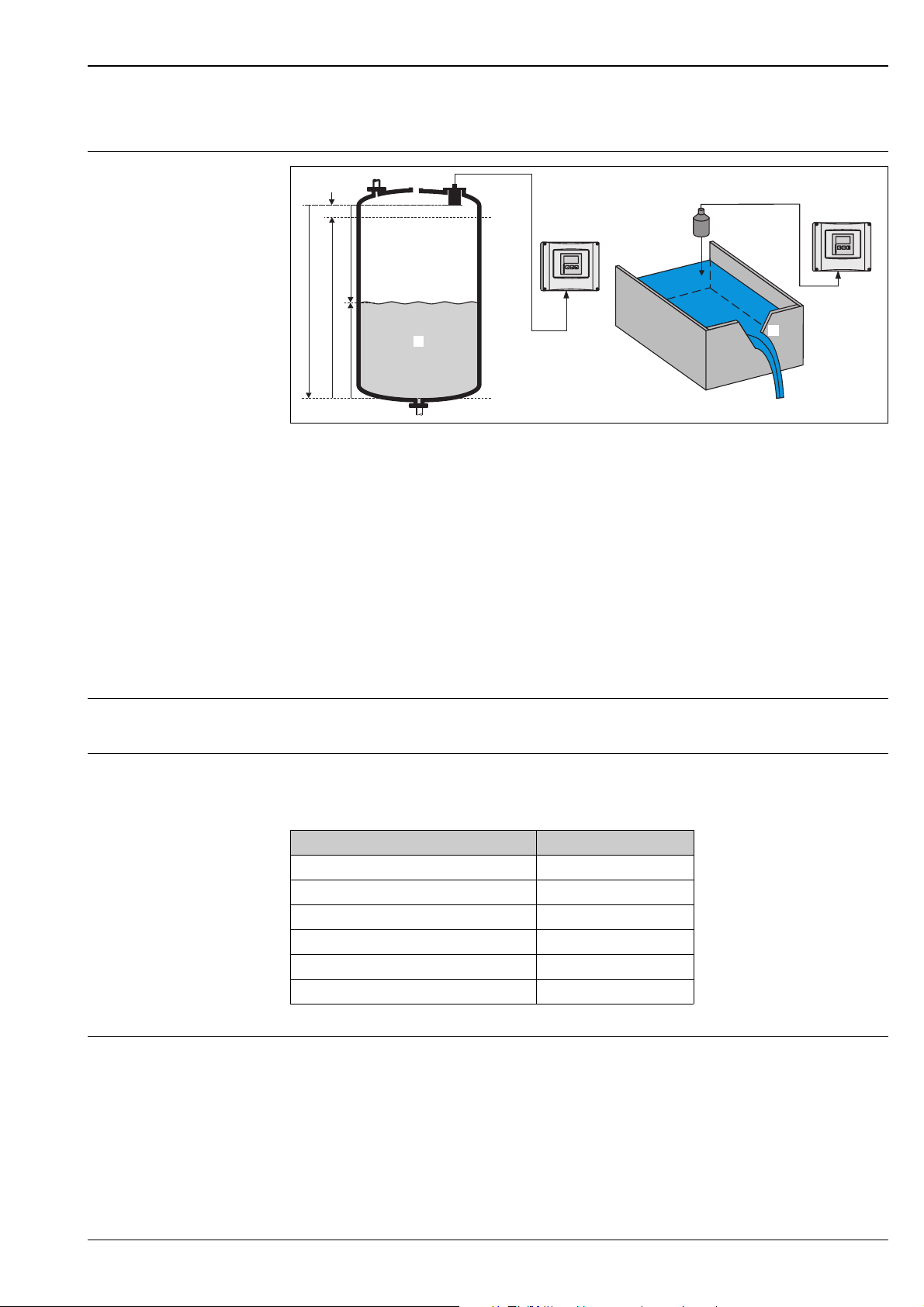
Measuring principle
FDU9x
BD
D
E
F
L
BD: blocking distance; D: distance from sensor membrane to fluid surface; E: empty ditance F: span (full distance); L:
level; V: volume (or mass); Q: flow
V
100%
0%
Prosonic S
FMU90
FDU9x
D
Q
Prosonic S
FMU90
L00-FMU90xxx-15-00-08-xx-009
The sensor transmits ultrasonic pulses in the direction of the product surface. There, they are reflected back
and received by the sensor. The transmitter Prosonic S measures the time t between pulse transmission and
reception. From t (and the velocity of sound c) it calculates the distance D from the sensor membrane to the
product surface:
D = c · t/2
From D results the desired measuring value:
• level L
•volume V
• flow Q across measuring weirs or open channels
Time-of-flight correction In order to compensate for temperature dependent time-of-flight changes, a temperature sensor is integrated
in every sensor.
Blocking distance The level L may not extend into the blocking distance BD. Level echoes from the blocking distance can not be
evaluated due to the transient characteristics of the sensor and thus a reliable measurement is not possible.
The blocking distance BD is dependent on the type of sensor:
Type of sensor Blocking distance (BD)
FDU91 0,3 m
FDU92 0,5 m
FDU93 0,6 m
FDU95 - *1*** (low temperature version) 0,7 m
FDU95 - *2*** (high temperature version) 0,9 m
FDU96 1,6 m
Transmitter The sensors can be connected to the transmitter FMU90. The transmitter recognizes the type of sensor
automatically.
Endress + Hauser 3
Prosonic S FDU91/92/93/95/96
Input
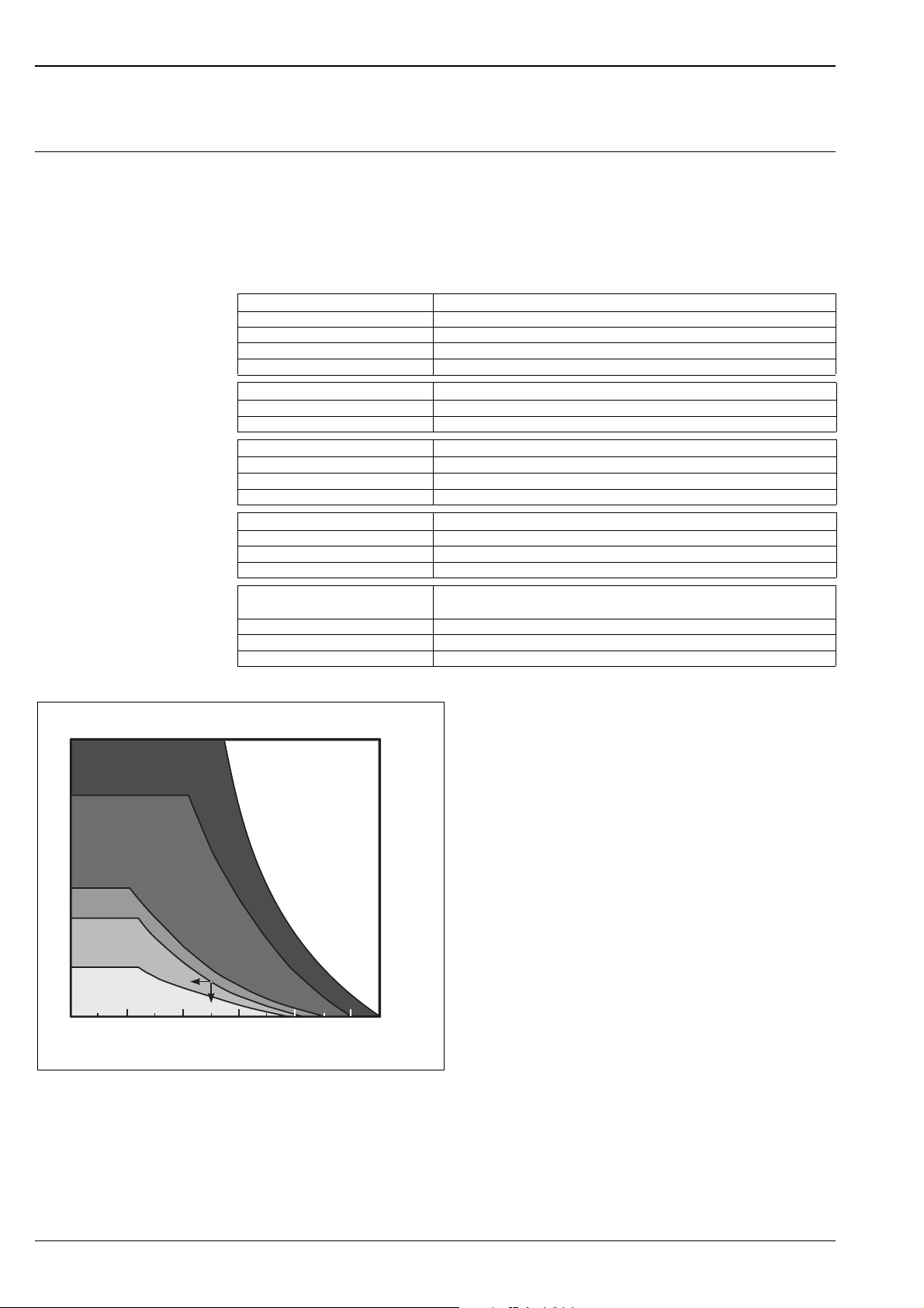
Measuring range The effective range of the sensors is dependent on the operating conditions. To estimate the range, proceed as
follows (see also the example):
1. Determine which of the influences shown in the following table are appropriate for your process.
2. Add the corresponding attenuation values.
3. From the total attenuation, use the diagram to calculate the range.
Fluid surface Attenuation
calm 0 dB
waves 5 ... 10 dB
strong turbulence (e.g. stirrers) 10 ... 20 dB
foaming ask Endress+Hauser
Bulk material surface Attenuation
hard, rough (e.g. rubble) 40 dB
soft (e.g. peat, dust-covered clinker) 40 ... 60 dB
Dust Attenuation
no dust formation 0 dB
little dust formation 5 dB
heavy dust formation 5 ... 20 dB
Filling curtain in detection range Attenuation
none 0 dB
small quantities 5 dB
large quantities 5 ... 20 dB
Temperature difference between
sensor and product surface
to 20 °C 0 dB
to 40 °C 5 ... 10 dB
to 80 °C 10 ... 20 dB
Attenuation
R [m]
70
FDU 96
45
FDU 95
25
FDU 93
20
FDU 92
10
FDU 91
0
0 20 40 60 80 100
A: Attenuation (dB); R: Range (m)
110
A [dB]
L00-FDU9xxxx-05-00-00-xx-001
Example
• Silo with rubble: ~ 40dB
• small quantities of
filling curtain: ~ 5dB
• little dust: ~ 5dB
total: ~ 50dB
=> Range approx. 8 m
for FDU92
4 Endress + Hauser

Prosonic S FDU91/92/93/95/96
Operating frequency
Sensor Operating frequency
FDU91 43 kHz
FDU92 30 kHz
FDU93 27 kHz
FDU95 - *1***
(low temperature version)
FDU95 - *2***
(high temperature version)
FDU96 11 kHz
Output
Signal transmission analogue voltages
Auxiliary energy
Power supply via transmitter FMU90
17 kHz
18 kHz
Endress + Hauser 5
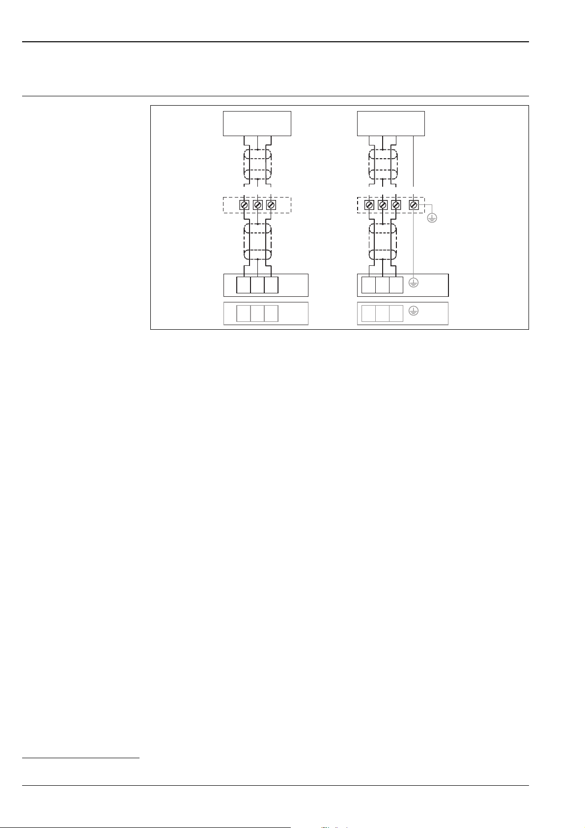
Connection to the transmitter
Prosonic S FMU90
Electrical connection
FDU91/92
Prosonic S FDU91/92/93/95/96
FDU93/95/96
<30m
RD
BK
YE
(A)
< 300 m
BK
RD
YE
(1)
9
BK
YE
(2)
12
(A): Terminal box (recommended or cable lengths > 30 m); (B): Grounding at the terminal box; (C): Grounding at the
transmitter or in the control room; (1): Terminals for sensor input 1 at the FMU9x; (2): Terminals for sensor input at the
FMU9x (optional)
FMU9x
10
11
RD
FMU9x
13
14
<30m
(A)
< 300 m
(1)
(2)
YE
YE
YE
12
GNYE
RD
BK
(B)
(C)
RD
BK
9
10
11
BK
RD
13
14
FMU9x
FMU9x
L00-FMU90xxx-04-00-00 -xx-002
Terminal assignment
The strand-colour of the sensor cable must correspond to the terminal designation at the FMU90:
•RD: red
• BK: black (after shortening of the cable: braided wire screen)
• YE: yellow
• GNYE: green-yellow (for FDU93/95/96 and FDU83/84/85/86)
!
"
"
Connecting options
• up to 30 m: direct connection via tha sensor cable
• 30 ... 300 m: extension cable recommended; connection via a terminal box (A)
Note!
Terminal box and extension cable are not supplied.
Caution!
If the terminal box is installed in explosion hazardous areas, then all national guidelines applicable must be
observed.
Caution!
The cable screen serves as a return cable and must be connected to the transmitter without any electrical break.
This must be taken into account especially if the cable is shortened.
In the unshortened state, the cables are pre-assembled and the cable screen ends in a black strand (BK).
Cable specifications
1
Required properties of the extension cable
:
• Two core cable, with braided wire screen per core (no foil screen)
• Length: up to 300 m (sensor cable + extension cable)
• Cross section: 0,75 mm
2
to 2,5 mm
2
•up to 6 Ω per core
• max. 60 nF
• for FDU93/95/96 and FDU83/84/85/86:
The earth lead must not be within the screening
1) for appropriate cable see chapter "Accessories"
6 Endress + Hauser
Prosonic S FDU91/92/93/95/96
Potential equalisation
(for FDU93/95/96 and FDU83/84/85/86)
The ground lead (GNYE) must be connected to the local potential equalisation. This can be done
• at the terminal box (B)
• at the transmitter FMU90 or in the cabinet (C)
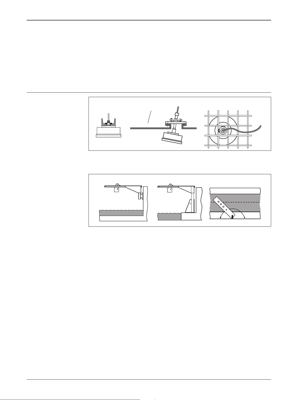
Installation conditions
Installation options
(Examples)
ABC
FAU40
L00-FDU9xxxx-17-00-00-xx-001
B
C
L00-FDU9xxxx-17-00-00-xx-007
-
Zone 20
-
Zone 21
.
A: at girder or angle bracket; B: with alignment unit FAU40; in ATEX Zone 20 the alignment unit can be used for zone
separation; C: with a 1" sleeve welded to a grating
A
FDU9x FDU9x
A: Installation with cantilever and wall bracket; B: Installation with cantilever and mounting frame; C: The cantilever can
be swivelled in order to position the sensor over the centre of the flume.
Cantilever, wall bracket and mounting frame are available as accessories (see chapter "Accessories").
Caution!
"
The cable of the sensors is not designed as a supporting cable. Do not use it as a suspension wire.
Caution!
"
The sensor membrane is part of the measuring system and must not be damaged during installation.
Endress + Hauser 7
 Loading...