

Endress+Hauser Prosonic S FDU93, Prosonic S FDU90 Technical Information
Technical Information
Prosonic S
FDU90/91/91F/92/93/95/96
Ultrasonic sensors for non-contact continuous
level and flow measurement;
for connection to the transmitters FMU90 and FMU95
FDU91
FDU90
FDU91F
Application
• Continuous, non-contact level measurement of fluids,
pastes, sludges and powdery to coarse bulk materials
• Flow measurement in open channels and measuring
weirs
• Maximum measuring range
– FDU90:
3 m in fluids
1.2 m in bulk materials
– FDU91/FDU91F:
10 m in fluids
5 m in bulk materials
– FDU92:
20 m in fluids
10 m in bulk materials
– FDU93:
25 m in fluids
15 m in bulk materials
– FDU95:
45 m in bulk materials
– FDU96:
70 m in bulk materials
• Suited for explosion hazardous areas
FDU92
FDU95
FDU93
FDU96
Your benefits
• Non-contact measurement method; minimizes service
requirements
• Integrated temperature sensor for time-of-flight
correction. Accurate measurements are possible, even
if temperature changes are present
• Hermetically welded PVDF sensors FDU91/92 for
fluid measurement; for highest chemical resistance
• Integrated automatical sensor detection for
transmitters FMU90; simple commissioning
• Can be installed up to 300 m from the transmitter
• Suited for rough ambient conditions thanks to separate
installation from the transmitter
• Reduced build-up formation because of the selfcleaning effect
• Integrated heating against a build-up of ice at the
sensor (optional); ensures reliable measurement
• Weather resistant and flood-proof (IP68)
• Dust-Ex and Gas-Ex certificats available (ATEX, FM,
CSA)
TI396F/00/en/07.09
71098284

Table of Contents
Prosonic S FDU90/91/91F/92/93/95/96
Function and system design. . . . . . . . . . . . . . . . . . . . . 3
Measuring principle . . . . . . . . . . . . . . . . . . . . . . . . . . . . . . . . . . . 3
Time-of-flight correction . . . . . . . . . . . . . . . . . . . . . . . . . . . . . . . . 3
Blocking distance . . . . . . . . . . . . . . . . . . . . . . . . . . . . . . . . . . . . . 4
Transmitter . . . . . . . . . . . . . . . . . . . . . . . . . . . . . . . . . . . . . . . . . 4
Input . . . . . . . . . . . . . . . . . . . . . . . . . . . . . . . . . . . . . . 5
Measuring range . . . . . . . . . . . . . . . . . . . . . . . . . . . . . . . . . . . . . . 5
Operating frequency . . . . . . . . . . . . . . . . . . . . . . . . . . . . . . . . . . . 6
Output . . . . . . . . . . . . . . . . . . . . . . . . . . . . . . . . . . . . . 6
Signal transmission . . . . . . . . . . . . . . . . . . . . . . . . . . . . . . . . . . . . 6
Auxiliary energy . . . . . . . . . . . . . . . . . . . . . . . . . . . . . 6
Power supply . . . . . . . . . . . . . . . . . . . . . . . . . . . . . . . . . . . . . . . . 6
Sensor heater (for FDU91) . . . . . . . . . . . . . . . . . . . . . . . . . . . . . . 6
Electrical connection . . . . . . . . . . . . . . . . . . . . . . . . . . 7
Connection diagram . . . . . . . . . . . . . . . . . . . . . . . . . . . . . . . . . . . 7
Connection hints . . . . . . . . . . . . . . . . . . . . . . . . . . . . . . . . . . . . . 8
Connection of the sensor heater (for FDU90/FDU91) . . . . . . . . . . 8
Extenxion cables for the sensors . . . . . . . . . . . . . . . . . . . . . . . . . . 8
Shortening the sensor cable . . . . . . . . . . . . . . . . . . . . . . . . . . . . . 9
Installation conditions . . . . . . . . . . . . . . . . . . . . . . . . 10
Installation options
(Examples) . . . . . . . . . . . . . . . . . . . . . . . . . . . . . . . . . . . . . . . . . 10
Mounting versions . . . . . . . . . . . . . . . . . . . . . . . . . . . . . . . . . . . 10
Installation conditions for level measurements . . . . . . . . . . . . . . 11
Installation conditions for flow measurements . . . . . . . . . . . . . . . 12
Flush mounting with
slip-on flange FAU80 . . . . . . . . . . . . . . . . . . . . . . . . . . . . . . . . . 13
Nozzle installation . . . . . . . . . . . . . . . . . . . . . . . . . . . . . . . . . . . 14
Ultrasound guide pipe . . . . . . . . . . . . . . . . . . . . . . . . . . . . . . . . . 15
Ambient conditions . . . . . . . . . . . . . . . . . . . . . . . . . . 16
Ingress protection . . . . . . . . . . . . . . . . . . . . . . . . . . . . . . . . . . . . 16
Vibration resistance . . . . . . . . . . . . . . . . . . . . . . . . . . . . . . . . . . 16
Storage temperature . . . . . . . . . . . . . . . . . . . . . . . . . . . . . . . . . . 16
Thermal shock resistance . . . . . . . . . . . . . . . . . . . . . . . . . . . . . . 16
Electromagnetic compatibility . . . . . . . . . . . . . . . . . . . . . . . . . . . 16
Materials . . . . . . . . . . . . . . . . . . . . . . . . . . . . . . . . . . . . . . . . . . 20
Connecting cable . . . . . . . . . . . . . . . . . . . . . . . . . . . . . . . . . . . . 20
Certificates and Approvals . . . . . . . . . . . . . . . . . . . . . 21
CE mark . . . . . . . . . . . . . . . . . . . . . . . . . . . . . . . . . . . . . . . . . . 21
Ex approval . . . . . . . . . . . . . . . . . . . . . . . . . . . . . . . . . . . . . . . . 21
External standards and guidelines . . . . . . . . . . . . . . . . . . . . . . . . 21
Ordering information. . . . . . . . . . . . . . . . . . . . . . . . . 22
Product structure FDU90 . . . . . . . . . . . . . . . . . . . . . . . . . . . . . . 22
Product structure FDU91 . . . . . . . . . . . . . . . . . . . . . . . . . . . . . . 23
Product structure FDU91F . . . . . . . . . . . . . . . . . . . . . . . . . . . . . 24
Product structure FDU92 . . . . . . . . . . . . . . . . . . . . . . . . . . . . . . 25
Product structure FDU93 . . . . . . . . . . . . . . . . . . . . . . . . . . . . . . 25
Product structure FDU95 . . . . . . . . . . . . . . . . . . . . . . . . . . . . . . 26
Product structure FDU96 . . . . . . . . . . . . . . . . . . . . . . . . . . . . . . 27
Scope of delivery . . . . . . . . . . . . . . . . . . . . . . . . . . . . . . . . . . . . 27
Accessories . . . . . . . . . . . . . . . . . . . . . . . . . . . . . . . . 28
Extension cable for sensors . . . . . . . . . . . . . . . . . . . . . . . . . . . . . 28
Protective cover for FDU91 . . . . . . . . . . . . . . . . . . . . . . . . . . . . 28
Flanges . . . . . . . . . . . . . . . . . . . . . . . . . . . . . . . . . . . . . . . . . . . 28
Flooding protection tube for FDU90 . . . . . . . . . . . . . . . . . . . . . . 29
Cantilever . . . . . . . . . . . . . . . . . . . . . . . . . . . . . . . . . . . . . . . . . 30
Mounting Frame . . . . . . . . . . . . . . . . . . . . . . . . . . . . . . . . . . . . 31
Wall Bracket . . . . . . . . . . . . . . . . . . . . . . . . . . . . . . . . . . . . . . . 31
Mounting bracket for ceiling mounting . . . . . . . . . . . . . . . . . . . . 32
Alignment unit FAU40 . . . . . . . . . . . . . . . . . . . . . . . . . . . . . . . 33
Power supply RNB130 for the FDU90/FDU91 sensor heater . . . 34
IP66 protective housing for the power supply RNB130 . . . . . . . . 34
Supplementary documentation . . . . . . . . . . . . . . . . . 35
Innovation booklet . . . . . . . . . . . . . . . . . . . . . . . . . . . . . . . . . . . 35
Technical Information . . . . . . . . . . . . . . . . . . . . . . . . . . . . . . . . 35
Operating instructions
(for transmitter FMU90) . . . . . . . . . . . . . . . . . . . . . . . . . . . . . . . 35
Description of Instrument Functions (for transmitter FMU90) . . . 35
Safety Instructions . . . . . . . . . . . . . . . . . . . . . . . . . . . . . . . . . . . 36
Process conditions . . . . . . . . . . . . . . . . . . . . . . . . . . . 16
Process temperature
Process pressure . . . . . . . . . . . . . . . . . . . . . . . . . . . . . . . . . . . . . 16
Mechanical construction . . . . . . . . . . . . . . . . . . . . . . 17
Counter nut G1 . . . . . . . . . . . . . . . . . . . . . . . . . . . . . . . . . . . . . 17
Dimensions FDU90 . . . . . . . . . . . . . . . . . . . . . . . . . . . . . . . . . . 17
Dimensions FDU91 . . . . . . . . . . . . . . . . . . . . . . . . . . . . . . . . . . 17
Dimensions FDU91F . . . . . . . . . . . . . . . . . . . . . . . . . . . . . . . . . 18
Dimensions FDU92 . . . . . . . . . . . . . . . . . . . . . . . . . . . . . . . . . . 18
Dimensions FDU93 . . . . . . . . . . . . . . . . . . . . . . . . . . . . . . . . . . 18
Dimensions FDU95 . . . . . . . . . . . . . . . . . . . . . . . . . . . . . . . . . . 19
Dimensions FDU96 . . . . . . . . . . . . . . . . . . . . . . . . . . . . . . . . . . 19
Weight . . . . . . . . . . . . . . . . . . . . . . . . . . . . . . . . . . . . . . . . . . . . 20
2 Endress + Hauser
Prosonic S FDU90/91/91F/92/93/95/96
Function and system design
Measuring principle
FDU9x
BD
D
E
F
L
BD: blocking distance; D: distance from sensor membrane to fluid surface; E: empty distance F: span (full distance);
L: level; V: volume (or mass); Q: flow
V
100%
0%
Prosonic S
FMU90
FDU9x
D
Q
Prosonic S
FMU90
L00-FMU90xxx-15-00-08-xx-009
The sensor transmits ultrasonic pulses in the direction of the product surface. There, they are reflected back
and received by the sensor. The transmitter Prosonic S measures the time t between pulse transmission and
reception. From t (and the velocity of sound c) it calculates the distance D from the sensor membrane to the
product surface:
D = c · t/2
From D results the desired measuring value:
• level L
• volume V
• flow Q across measuring weirs or open channels
Time-of-flight correction In order to compensate for temperature dependent time-of-flight changes, a temperature sensor is integrated
in the ultrasonic sensors.
Endress + Hauser 3
Prosonic S FDU90/91/91F/92/93/95/96
Blocking distance The level L may not extend into the blocking distance BD. Level echoes within the blocking distance can not
be evaluated due to the transient characteristics of the sensor and thus a reliable measurement is not possible.
The blocking distance BD is dependent on the type of sensor:
FDU96
FDU95-#1###: 0.7 m (2.3 ft)
FDU95
FDU95-#2###: 0.9 m (3 ft)
1.6 m (5.25 ft)
L00-FDU9xxxx-05-00-00-xx-002
AB
0.07 m
(0.23 ft)
FDU90
FDU91
0.3 m (1 ft)
FDU92
0.4 m (1.3 ft)
FDU93
0.6 m (2 ft)
A: without flooding protection tube; B: with flooding protection tube
Transmitter The sensors can be connected to the transmitter FMU90. The transmitter recognizes the type of sensor
automatically.
4 Endress + Hauser
Prosonic S FDU90/91/91F/92/93/95/96
FDU 95
FDU 96
FDU 93
Input
Measuring range The effective range of the sensors is dependent on the operating conditions. To estimate the range, proceed as
follows (see also the example):
1. Determine which of the influences shown in the following table are appropriate for your process.
2. Add the corresponding attenuation values.
3. From the total attenuation, use the diagram to calculate the range.
Fluid surface Attenuation
calm 0 dB
waves 5 ... 10 dB
strong turbulence (e.g. stirrers) 10 ... 20 dB
foaming ask Endress+Hauser
Bulk material surface Attenuation
hard, rough (e.g. rubble) 40 dB
soft (e.g. peat, dust-covered clinker) 40 ... 60 dB
Dust Attenuation
no dust formation 0 dB
little dust formation 5 dB
heavy dust formation 5 ... 20 dB
Filling curtain in detection range Attenuation
none 0 dB
small quantities 5 dB
large quantities 5 ... 20 dB
Temperature difference between
sensor and product surface
to 20 °C 0 dB
to 40 °C 5 ... 10 dB
to 80 °C 10 ... 20 dB
Attenuation
R[m]
70
FDU 96
45
FDU 95
25
FDU 93
20
FDU 92
10
FDU 91(F)
3
FDU90
0
0204060 80 100
A: Attenuation (dB); R: Range (m)
110
A [dB]
L00-FDU9xxxx-05-00-00-xx-001
Example
• Silo with rubble: ~ 40dB
• small quantities of
filling curtain: ~ 5dB
• little dust: ~ 5dB
total: ~ 50dB
=> Range approx. 8 m
for FDU92
Endress + Hauser 5
Prosonic S FDU90/91/91F/92/93/95/96
Operating frequency
Sensor Operating frequency
FDU90 90 kHz
FDU91 43 kHz
FDU91F 42 kHz
FDU92 30 kHz
FDU93 27 kHz
FDU95 - *1***
(low temperature version)
FDU95 - *2***
(high temperature version)
FDU96 11 kHz
Output
Signal transmission analogue voltages
Auxiliary energy
17 kHz
18 kHz
Power supply supplied by the transmitter FMU90
Sensor heater (for FDU91) The FDU90 and FDU91 sensors are available in a version with heater. The power for this heater must be
provided by an external power supply unit. The supply voltage is connected to the brown (BN) and blue (BU)
strands of the sensor cable.
Technical data
• 24 VDC ±10%; residual ripple < 100 mV
• 250 mA per sensor
!
!
Note!
If the sensor heater is applied, the integrated temperature sensor can not be used. Instead, an external
temperature sensor (Pt100 or FMT131 from Endress+Hauser) must be used. The transmitter FMU90 is
available in a version with an input for the external temperature sensor. For details refer to Technical
Information TI397F.
Note!
The power for the sensor heater can be supplied by the power supply RNB130 from Endress+Hauser (see
chapter "Accessories").
6 Endress + Hauser
Prosonic S FDU90/91/91F/92/93/95/96
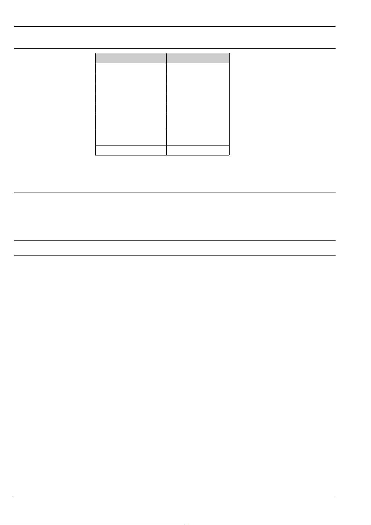
Electrical connection
Connection diagram
FDU90/91/92
(FDU80/80F/81/81F/82)
max.
300 m
max.
30 m
(A) (B)
FDU90/91/92
(FDU80/80F/81/81F/82)
(1)
RD
BK
YE
(2)
(3)
BK
RD
YE
10
9
11
(13)
(12)
(14)
FMU90
(C)
FDU91F/93/95/96
(FDU83/84/85/86)
(2)
FDU90/91
(FDU80/81)
(1)
BK
YE
(3)
BK
YE
10
9
(13)
(12)
FMU90
FDU91F/93/95/96
(FDU83/84/85/86)
RD
RD
11
(14)
(D)
BN BU
+
24VDC
-
FDU91F/93/95/96
(FDU83/84/85/86)
max.
300 m
max.
30 m
(2)
(1)
(3)
YE
YE
(12)
9
BK
BK
10
(13)
FMU90
RD
RD
11
(14)
GNYE
(1)
YE
YE
9
(12)
BK
BK
10
(13)
FMU90
RD
RD
11
(14)
(A): without sensor heater;
(B): with sensor heater;
(C): grounding at the terminal box;
(D): grounding at the transmitter FMU90;
(1): Screen of the sensor cable;
(2): Terminal box;
(3): Screen of the extension cable;
Colours of the strands: YE = yellow; BK = black; RD = red; BU = blue; BN = brown; GNYE = green-yellow
GNYE
L00-FDU9xxxx-04-00-00-xx-002
Endress + Hauser 7

Connection hints
"
"
#
#
!
Prosonic S FDU90/91/91F/92/93/95/96
Caution!
In order to avoid interference signals, the sensor cables should not be laid parallel to high voltage electric power
lines. The cables may not be laid in the proximity to frequency converters.
Caution!
The cable screen serves as a return cable and must be connected to the transmitter without any electrical break.
With the pre-assembled cables, the screen ends in a black strand (BK). With the extension cable, the screen
must be twisted together and connected to the "BK" terminal.
Warning!
The sensors FDU83, FDU84, FDU85 and FDU86 with an ATEX, FM or CSA certificate are not certified for
connection to the FMU90 transmitter.
Warning!
for the sensors FDU91F/93/95/96 and FDU83/84/85/86:
The ground lead (GNYE) must be connected to the local potential equalization after a maximum distance
of 30 m. This can be done
• either at the terminal box
• or at the transmitter FMU90 or in the cabinet (if the distance to the sensor does not exceed 30 m).
Note!
For easier mounting it is advisable to use the sensors FDU90/91/92 and FDU80/80F/81/81F/82 with a
maximum cable length of 30 m as well. For longer distances an extension cable with a terminal box should
be used.
Connection of the sensor
heater (for FDU90/FDU91)
!
Extenxion cables for the
sensors
The FDU90 and FDU91 sensors are available in a version with heater. The power for this heater must be
provided by an external power supply unit. The supply voltage is connected to the brown (BN) and blue (BU)
strands of the sensor cable.
Technical Data
• 24 VDC ± 10%; residual ripple < 100 mV
• 250 mA per sensor
Note!
When using the sensor heater, the temperature compensation of the ultrasonic measurement must be
performed with an external temperature probe, which is connecte to the additional temperature input of the
FMU90 transmitter (see Technical Information TI397F).
For distances up to 30 m the sensor can be directly connected by the sensor cable. For longer distances, it is
recommended to use an extension cable. The extension cable is connected via a terminal box. The total length
(sensor cable + extension cable) may be up to 300 m.
Caution!
"
If the terminal box is installed in explosion hazardous areas, all applicable national guidelines must be observed.
Suitable extension cables can be obtained from Endress+Hauser (s. chapter "Accessories")
Alternatively, cables with the following properties can be used:
• Number of cores according to the connection diagram (see above)
• braided wire screen for the yellow (YE) and red (RD) core (no foil screen)
• Length: up to 300 m (sensor cable + extension cable)
• Cross section: 0,75 mm
• up to 6 Ω per core
• max. 60 nF
• for FDU91F/93/95/96 and FDU 83/84/85/86:
The earth lead must not be within the screening.
2
to 2,5 mm
2
8 Endress + Hauser
Prosonic S FDU90/91/91F/92/93/95/96
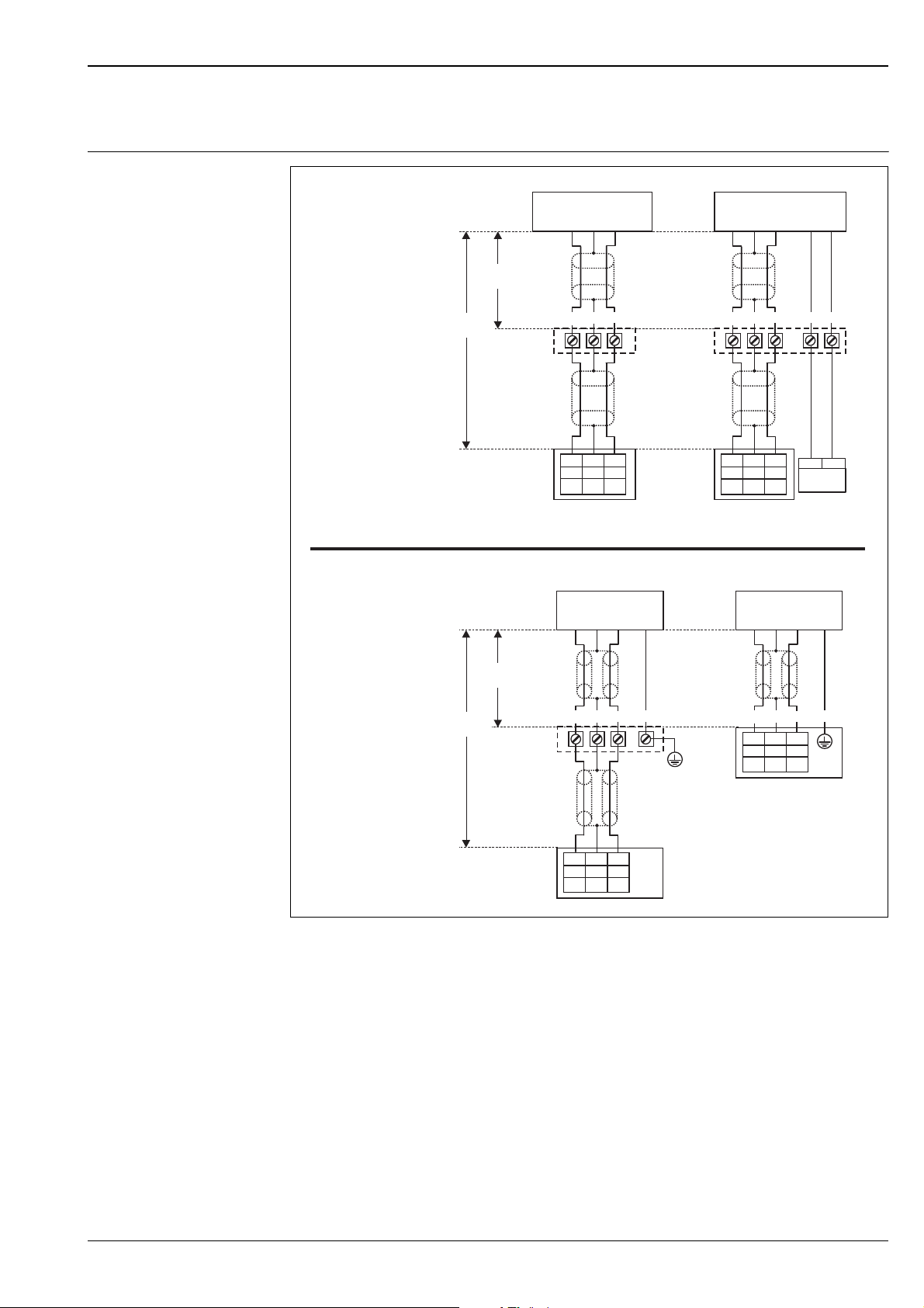
Shortening the sensor cable If required, the sensor cable can be shortened. Please note:
• Do not damage the cores when removing the insulation.
• The cable is shielded by a metallic braiding. This shielding serves as a return cable and corresponds to the
black (BK) strand of the unshortened cable. After shortening the cable, loosen the metallic braiding, twist it
together securely and connect it to the "BK" terminal.
Caution!
"
The protective earth conductor (GNYE), which is present in some of the sensor cables, may not be electrically
connected to the cable shield.
FDU90/91/92
(FDU80/80F/81/81F/82)
1. 1.
YE
BU
BN
RD
BN (+)
BU (-)
24VDC
RD
BK
YE
FDU91F/93/95/96
(FDU83/84/85/86)
GNYE
YE
GNYE
RD
RD
BK
YE
L00-FMU90xxx-04-00-00-xx-015
Colours of the strands: YE = yellow; BK = black; RD = red; BU = blue; BN = brown; GNYE = green-yellow
!
Note!
The blue (BU) and brown (BN) strands are only present for sensors with heater.
Endress + Hauser 9
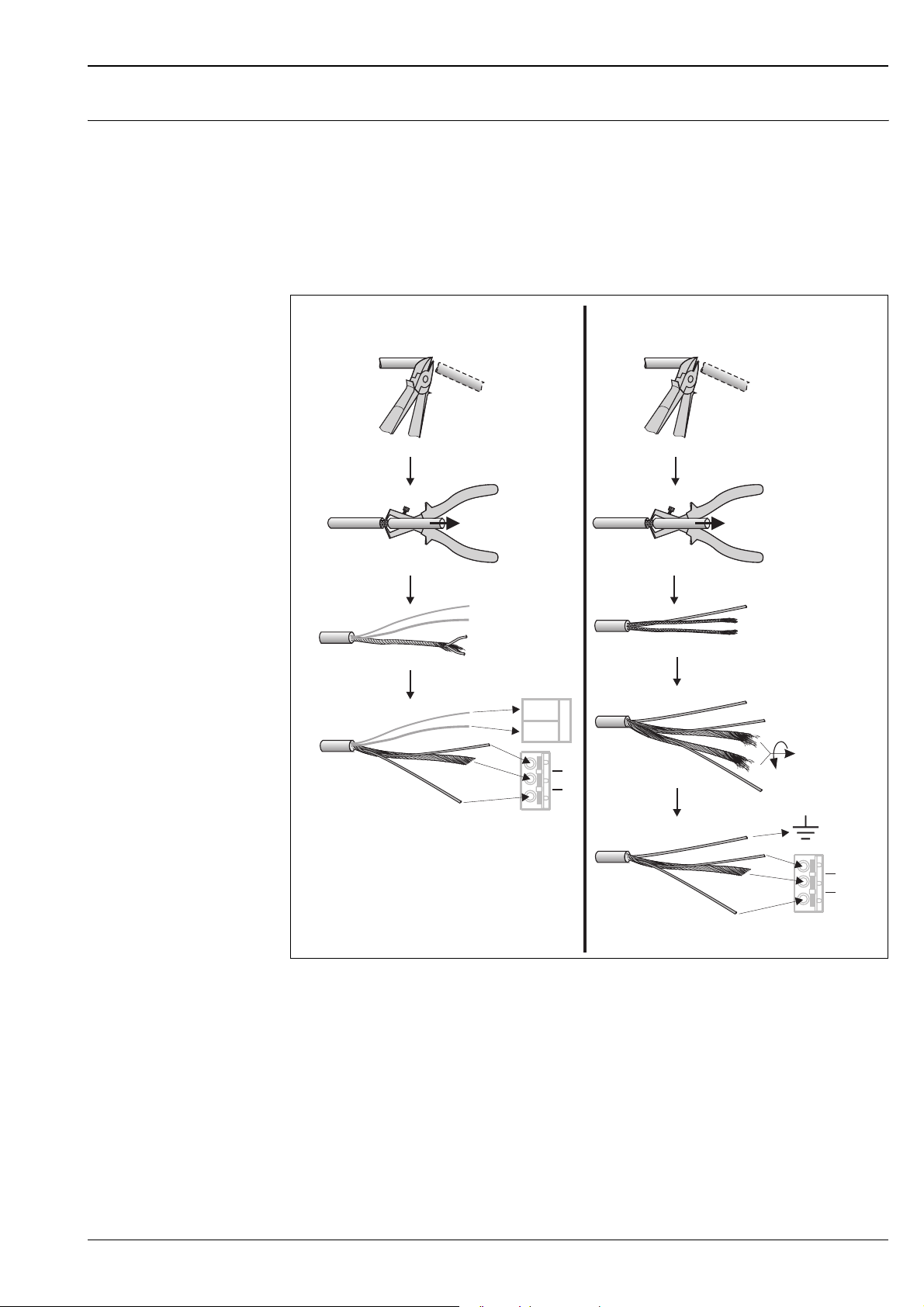
Installation conditions
Prosonic S FDU90/91/91F/92/93/95/96
Installation options
(Examples)
ABC
FAU40
L00-FDU9xxxx-17-00-00-xx-001
B
C
L00-FDU9xxxx-17-00-00-xx-007
-
Zone 20
-
Zone 21
.
A: at girder or angle bracket; B: with alignment unit FAU40; in ATEX Zone 20 the alignment unit can be used for zone
separation; C: with a 1" sleeve welded to a grating
A
FDU9x FDU9x
A: Installation with cantilever and wall bracket; B: Installation with cantilever and mounting frame; C: The cantilever can
be turned in order to position the sensor over the centre of the flume.
Cantilever, wall bracket and mounting frame are available as accessories (see chapter "Accessories").
Mounting versions
Caution!
"
The cable of the sensors is not designed as a supporting cable. Do not use it as a suspension wire.
Caution!
"
The sensor membrane is part of the measuring system and must not be damaged during installation.
ABC D
SW41
41AF
FDU90
A: FDU90: Ceiling mounting
B: FDU90: Mounted at front thread (G1-1/2 or NPT1-1/2)
C: FDU9x: Mounted at rear thread (G1 or NPT1)
D: FDU90, FDU91, FDU91F, FDU92: Mounting with G1 counter nut
FDU90
FDU9x
1)
; 42AF
FDU9x
L00-FDU90xxxx-17-00-00-xx-001
1) The counter nut with gasket is supplied for the sensors FDU90, FDU91, FDU91F and FDU92 with a metric thread G1 at the process connection.
10 Endress + Hauser
Prosonic S FDU90/91/91F/92/93/95/96
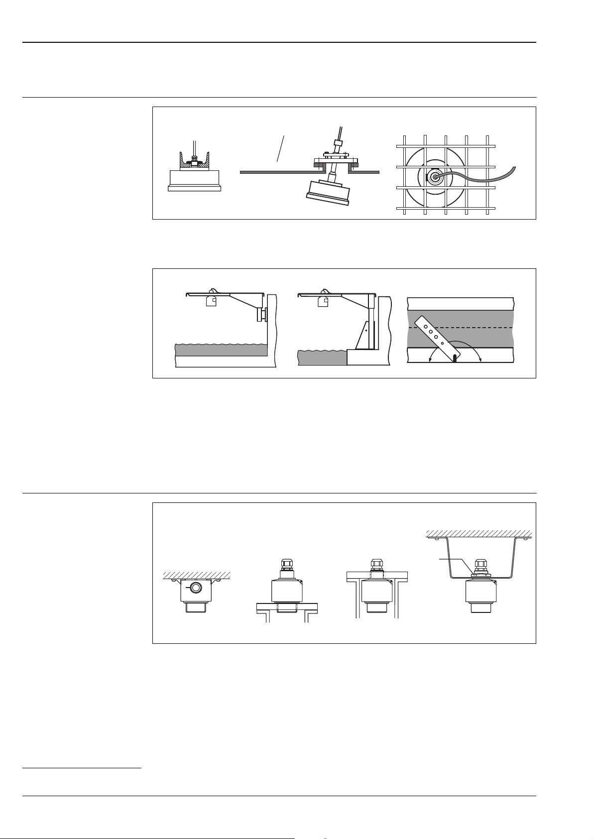
Installation conditions for
level measurements
2
3
6
BD
BD
1
1/6D
D
4
5
L
α
r
BD
L00-FDU9xxxx-17-00-00-xx-003
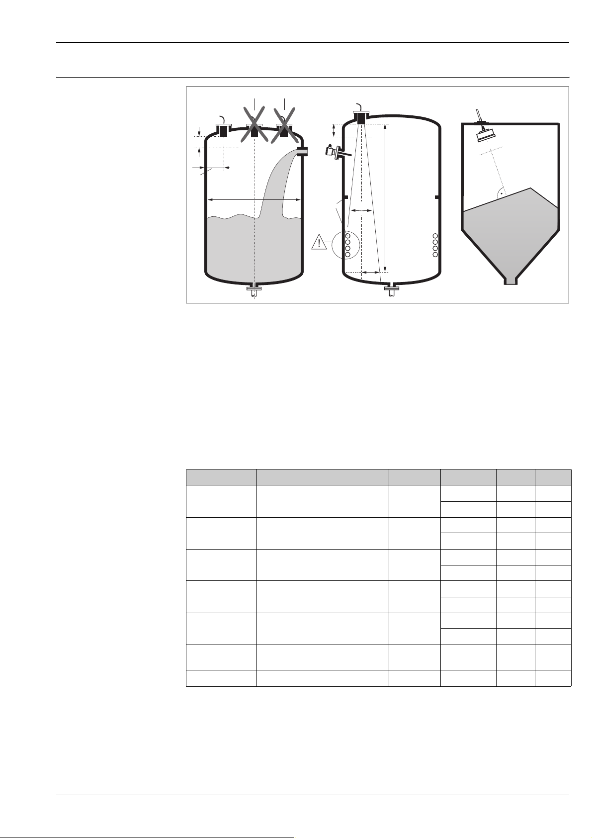
• If possible, install the sensor so that its lower edge projects into the vessel.
• Make sure, that the maximum level does not reach into the blocking distance (BD, see table).
• Do not install the sensor in the middle of the tank (2). We recommend leaving a distance (1) between the
sensor and the tank wall measuring 1/6 of the tank diameter.
• Avoid measurements through the filling curtain (3).
• Make sure that equipment (4) such as limit switches, temperature sensors, baffles etc. are not located within
the emitting angle α. Emitting angles of the individual sensors are given in the table below. In particular,
symmetrical equipment (5) such as heating coils etc. can influence the measurement.
• Align the sensor vertically to the product surface (6). An alignment unit (FAU40) is available as an accessory
(see chapter "Accessories").
• If the two-channel version of the transmitter FMU90 is used, both sensors can be mounted in one vessel.
• To estimate the detection range, use the 3 dB emitting angle α:
#
Sensor Blocking distance BD α (typically) Application L (max) r (max)
FDU90 0.07 m 12°
FDU91 0.3 m 9°
FDU91F 0.3 m 12°
FDU92 0.4 m 11°
FDU93 0.6 m 4°
FDU95 • 0.7 m (low temperature version)
• 0.9 m (high temperature version)
FDU96 1.6 m 6° bulk materials 70 m 3.6 m
5° bulk materials 45 m 1.96 m
fluids 3 m 0.31 m
bulk materials 1.2 m 0.13 m
fluids 10 m 0.79 m
bulk materials 5 m 0.39 m
fluids 10 m 1.05 m
bulk materials 5 m 0.53 m
fluids 20 m 1.92 m
bulk materials 10 m 0.96 m
fluids 25 m 0.87 m
bulk materials 15 m 0.52 m
Warning!
All national guidelines applicable must be observed in explosion hazardous areas.
Endress + Hauser 11
Prosonic S FDU90/91/91F/92/93/95/96
Installation conditions for flow
measurements
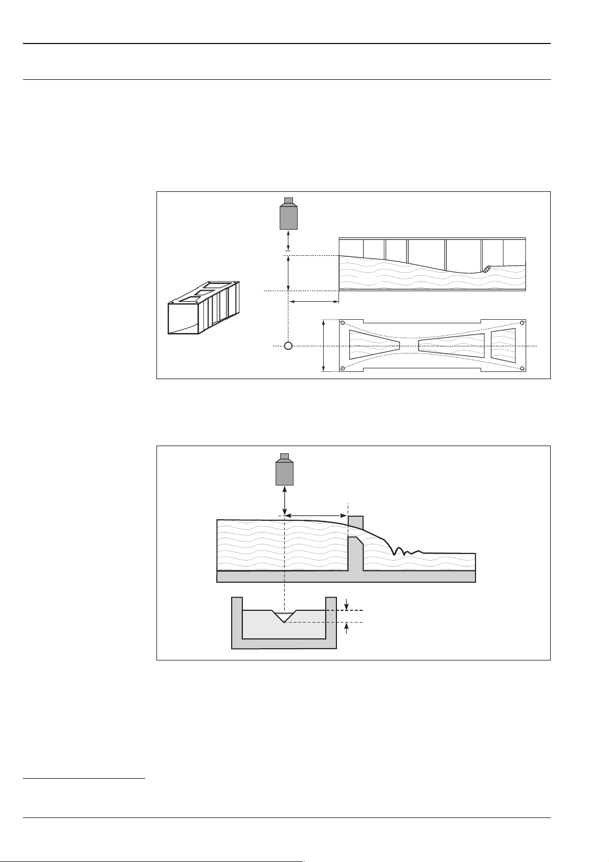
• Install the sensor at the inflow side (A), above the maximum water level H
plus the blocking distance BD.
max
• Position the sensor in the middle of the channel or weir.
• Align the sensor vertically to the water surface.
• Comply to the installation distance of the channel or weir.
2)
• Use a protective cover, in order to protect the sensor from direct sun or rain. A protective cover is available
for the sensors FDU90 and FDU91 (see chapter "Accessories").
Example: Khafagi-Venturi flume
FDU 91
(A): inflow side; (B): outflow side
H
BD
max
1 x b
0
b
0
(A) (B)
L00-FDU9xxxx-17-00-00-xx-004
Example: V-notch weir
FDU 91
BD
min. 3 H
max
H
max
L00-FDU9xxxx-17-00-00-xx-005
2) The installation distances of important flumes and weirs are specified in the Operating Instructions BA 289F (FMU90 with HART) and BA 293F (FMU90 with
PROFIBUS).
12 Endress + Hauser
 Loading...