

Endress+Hauser Prosonic M FMU40, Prosonic M FMU41, Prosonic M FMU42, Prosonic M FMU43, Prosonic M FMU44 Brief Operating Instructions
KA01063F/00/EN/13.11
71145352
Brief Operating Instructions
Prosonic M FMU40/41/42/43/44
Ultrasonic Level Measurement
These Instructions are Brief Operating Instructions; they do not replace the
Operating Instructions included in the scope of supply.
For detailed information, refer to the Operating Instructions and other
documentation on the CD-ROM provided or visit "www.endress.com/
deviceviewer".

Prosonic M PROFIBUS PA
2
Table of contents
1 Safety instructions . . . . . . . . . . . . . . . . . . . . . . . . . . . . . . . . . . . . . . . . . . 3
1.1 Designated use . . . . . . . . . . . . . . . . . . . . . . . . . . . . . . . . . . . . . . . . . . . . . . . . . . . . . . . . . . . . . . . 3
1.2 Installation, commissioning and operation . . . . . . . . . . . . . . . . . . . . . . . . . . . . . . . . . . . . . . . . . . . 3
1.3 Operational safety and process safety . . . . . . . . . . . . . . . . . . . . . . . . . . . . . . . . . . . . . . . . . . . . . . 3
1.4 Return . . . . . . . . . . . . . . . . . . . . . . . . . . . . . . . . . . . . . . . . . . . . . . . . . . . . . . . . . . . . . . . . . . . . . 4
1.5 Safety icons . . . . . . . . . . . . . . . . . . . . . . . . . . . . . . . . . . . . . . . . . . . . . . . . . . . . . . . . . . . . . . . . . 4
2 Mounting. . . . . . . . . . . . . . . . . . . . . . . . . . . . . . . . . . . . . . . . . . . . . . . . . 4
2.1 Incoming acceptance, storage . . . . . . . . . . . . . . . . . . . . . . . . . . . . . . . . . . . . . . . . . . . . . . . . . . . . 4
2.2 Installation . . . . . . . . . . . . . . . . . . . . . . . . . . . . . . . . . . . . . . . . . . . . . . . . . . . . . . . . . . . . . . . . . . 5
2.3 Installation conditions . . . . . . . . . . . . . . . . . . . . . . . . . . . . . . . . . . . . . . . . . . . . . . . . . . . . . . . . . 7
2.4 Measuring range . . . . . . . . . . . . . . . . . . . . . . . . . . . . . . . . . . . . . . . . . . . . . . . . . . . . . . . . . . . . 10
2.5 Installation hint for FMU40/41 . . . . . . . . . . . . . . . . . . . . . . . . . . . . . . . . . . . . . . . . . . . . . . . . . 13
2.6 Turn housing . . . . . . . . . . . . . . . . . . . . . . . . . . . . . . . . . . . . . . . . . . . . . . . . . . . . . . . . . . . . . . . 14
2.7 Installation check . . . . . . . . . . . . . . . . . . . . . . . . . . . . . . . . . . . . . . . . . . . . . . . . . . . . . . . . . . . . 14
3 Wiring . . . . . . . . . . . . . . . . . . . . . . . . . . . . . . . . . . . . . . . . . . . . . . . . . . 15
3.1 Wiring in F12/F23 housing . . . . . . . . . . . . . . . . . . . . . . . . . . . . . . . . . . . . . . . . . . . . . . . . . . . . 15
3.2 Wiring in T12 housing . . . . . . . . . . . . . . . . . . . . . . . . . . . . . . . . . . . . . . . . . . . . . . . . . . . . . . . . 16
3.3 Wiring with M12 connector . . . . . . . . . . . . . . . . . . . . . . . . . . . . . . . . . . . . . . . . . . . . . . . . . . . . 16
3.4 Pin assignment of the M12 plug connector (PROFIBUS PA plug) . . . . . . . . . . . . . . . . . . . . . . . . . 17
3.5 Terminal assignment . . . . . . . . . . . . . . . . . . . . . . . . . . . . . . . . . . . . . . . . . . . . . . . . . . . . . . . . . 17
3.6 Cable specification PROFIBUS . . . . . . . . . . . . . . . . . . . . . . . . . . . . . . . . . . . . . . . . . . . . . . . . . . 17
3.7 Supply voltage . . . . . . . . . . . . . . . . . . . . . . . . . . . . . . . . . . . . . . . . . . . . . . . . . . . . . . . . . . . . . . 18
3.8 Recommended connection . . . . . . . . . . . . . . . . . . . . . . . . . . . . . . . . . . . . . . . . . . . . . . . . . . . . . 18
3.9 Checking the connection . . . . . . . . . . . . . . . . . . . . . . . . . . . . . . . . . . . . . . . . . . . . . . . . . . . . . . 19
4 Operation . . . . . . . . . . . . . . . . . . . . . . . . . . . . . . . . . . . . . . . . . . . . . . . 20
4.1 Operating options . . . . . . . . . . . . . . . . . . . . . . . . . . . . . . . . . . . . . . . . . . . . . . . . . . . . . . . . . . . . 20
4.2 General structure of the operating menu . . . . . . . . . . . . . . . . . . . . . . . . . . . . . . . . . . . . . . . . . . . 20
4.3 Display and operating elements . . . . . . . . . . . . . . . . . . . . . . . . . . . . . . . . . . . . . . . . . . . . . . . . . . 21
4.4 Device address . . . . . . . . . . . . . . . . . . . . . . . . . . . . . . . . . . . . . . . . . . . . . . . . . . . . . . . . . . . . . . 24
5 Commissioning . . . . . . . . . . . . . . . . . . . . . . . . . . . . . . . . . . . . . . . . . . . 25
5.1 Function check . . . . . . . . . . . . . . . . . . . . . . . . . . . . . . . . . . . . . . . . . . . . . . . . . . . . . . . . . . . . . 25
5.2 Switching on the measuring device . . . . . . . . . . . . . . . . . . . . . . . . . . . . . . . . . . . . . . . . . . . . . . . 25
5.3 Basic Setup . . . . . . . . . . . . . . . . . . . . . . . . . . . . . . . . . . . . . . . . . . . . . . . . . . . . . . . . . . . . . . . . . 26

Prosonic M PROFIBUS PA Safety instructions
Endress+Hauser 3
1 Safety instructions
1.1 Designated use
The Prosonic M is a compact measuring device for continuous, non-contact level measurement.
Depending on the sensor, the measuring range is up to 20 m (66 ft) in fluids and up to 10 m
(33 ft) in bulk solids. By using the linearisation function, the Prosonic M can also be used for
flow measurements in open channels and measuring weirs.
1.2 Installation, commissioning and operation
• The device must only be installed, connected, commissioned and maintained by qualified and
authorized specialists (e.g. electrical technicians) in full compliance with the instructions in
this manual, the applicable norms, legal regulations and certificates (depending on the
application).
• The specialist must have read and understood this manual and must follow the instructions it
contains. If you are unclear on anything in these Brief Operating Instructions, you must read
the Operating Instructions (on the CD-ROM). The Operating Instructions provide detailed
information on the device/measuring system.
• The device may only be modified or repaired if such work is expressly permitted in the
Operating Instructions (→ see CD-ROM).
• If faults cannot be rectified, the device must be taken out of service and secured against
unintentional commissioning.
• Do not operate damaged devices. Mark them as defective.
1.3 Operational safety and process safety
• Alternative monitoring measures must be taken to ensure operational safety and process safety
during confiugration, testing and maintenance work on the device.
• The device is safely built and tested according to state-of-the-art technology and has left the
factory in perfect condition as regards technical safety. The applicable regulations and
European standards have been taken into account.
• Pay particular attention to the technical data on the nameplate.
• If the device is to be installed in an explosion hazardous area, then the specifications in the
certificate as well as all national and local regulations must be observed. The device is
accompanied by separate "Ex documentation", which is an integral part of this Operating
Instructions. The installation regulations, connection values and Safety Instructions listed in
this Ex document must be observed. The documentation number of the related Safety
Instructions is also indicated.
• If using devices for applications with safety integrity level, the separate manual on functional
safety must be observed thoroughly (→ see CD-ROM).

Mounting Prosonic M PROFIBUS PA
4 Endress+Hauser
1.4 Return
Follow the instructions on returning the device as outlined in the Operating Instructions on the
CD-ROM provided.
1.5 Safety icons
2 Mounting
2.1 Incoming acceptance, storage
2.1.1 Incoming acceptance
Check the packing and contents for any signs of damage. Check the shipment, make sure
nothing is missing and that the scope of supply matches your order.
2.1.2 Storage
Pack the measuring instrument so that is protected against impacts for storage and transport. The
original packing material provides the optimum protection for this.
The permissible storage temperature is -40 °C to +80 °C (-40 °F to +176 °F).
Symbol Meaning
#
Warning!
A warning highlights actions or procedures which, if not performed correctly, will lead to personal injury,
a safety hazard or destruction of the instrument.
"
Caution!
Caution highlights actions or procedures which, if not performed correctly, may lead to personal injury or
incorrect functioning of the instrument.
!
Note!
A note highlights actions or procedures which, if not performed correctly, may indirectly affect operation
or may lead to an instrument response which is not planned.
Prosonic M PROFIBUS PA Mounting
Endress+Hauser 5
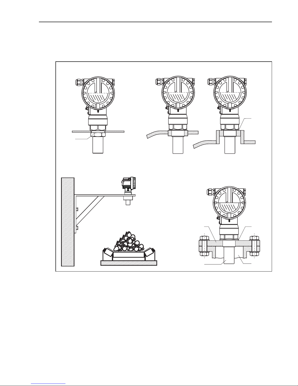
2.2 Installation
2.2.1 Installation variants FMU40, FMU41
L00-FMU4xxxx-17-00-00-yy-002
A Installation with counter nut
1 Counter nut (PC) supplied for G1½ and G2 instruments
B Installation with sleeve
1 Sealing ring (EPDM) supplied
C Installation with installation bracket
D Installation with screw in flange
1 Sealing ring (EPDM) supplied
2 Nozzle
3Sensor
4 Screw in flange
ENDRESS+HAUSER
Prosonic M
AB
C
D
1
1
1
2
3
4
Mounting Prosonic M PROFIBUS PA
6 Endress+Hauser
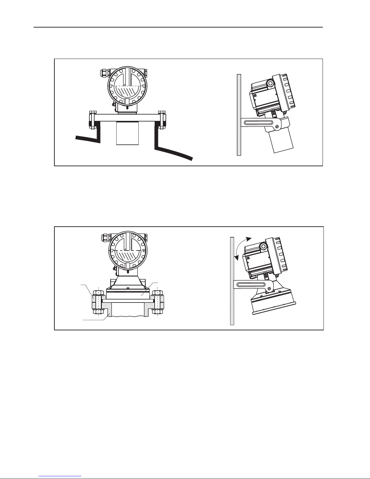
2.2.2 Installation variants FMU42, FMU44
L00-FMU42xxxx-17-00-00-xx-002
A Installation with universal flansch
B Installation with mounting bracket
2.2.3 Installation variants FMU43
L00-FMU43xxxx-17-00-00-x-002
A Installation with universal slip-on flange (option)
1Sensor
2 Nozzle
3 Slip-on flange
B Installation with mounting bracket
ENDRESS+HAUSER
ProsonicM
AB
ENDRESS+HAUSER
ProsonicM
1
3
2
A
B
Prosonic M PROFIBUS PA Mounting
Endress+Hauser 7
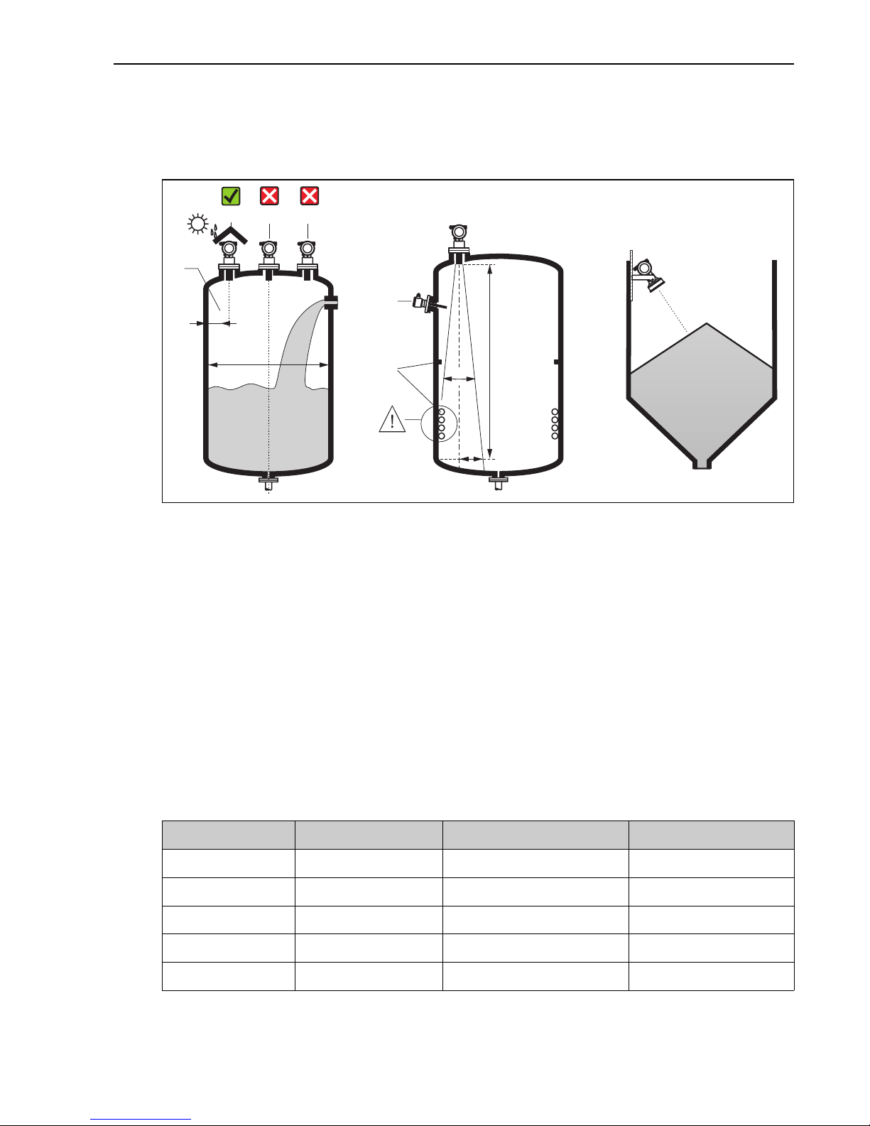
2.3 Installation conditions
2.3.1 Installation conditions for level measurements
L00-FMU4xxxx-17-00-00-yy-005
• Do not install the sensor in the middle of the tank (3). We recommend leaving a distance
between the sensor and the tank wall (1) measuring 1/6 of the tank diameter.
• Use a protective cover, in order to protect the device from direct sun or rain (2) see the
Technical Information TI00365F, Chapter "Accessories" on the CD-ROM provided.
• Avoid measurements through the filling curtain (4).
• Make sure that equipment (5) such as limit switches, temperature sensors, etc. are not located
within the emitting angle α. In particular, symmetrical equipment (6) such as heating coils,
baffles etc. can influence measurement.
• Align the sensor so that it is vertical to the product surface (7).
• Never install two ultrasonic measuring devices in a tank, as the two signals may affect each
other.
• To estimate the detection range, use the 3 dB emitting angle α.
Sensor α L
max
r
max
FMU40 11° 5 m (16 ft) 0.48 m (1.6 ft)
FMU41 11° 8 m (26 ft) 0.77 m (2.5 ft)
FMU42 9° 10 m (33 ft) 0.79 m (2.6 ft)
FMU43 6° 15 m (49 ft) 0.79 m (2.6 ft)
FMU44 11 ° 20 m (66 ft) 1.93 m (6.3 ft)
1
234
5
6
1/6D
7
D
r
a
L
Mounting Prosonic M PROFIBUS PA
8 Endress+Hauser
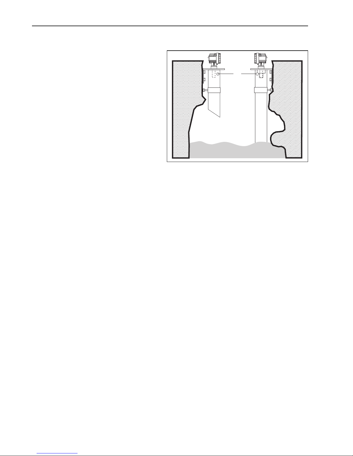
2.3.2 Installation in narrow shafts
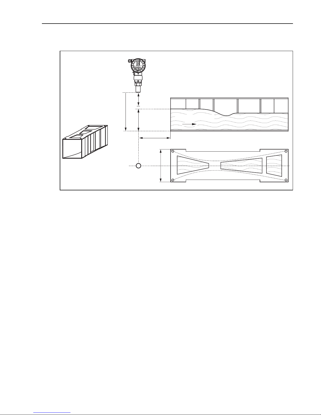
2.3.3 Installation conditions for flow measurements
• Install the Prosonic M at the inflow side, as close above the maximum water level H
max
as
possible (take into account the blocking distance BD).
• Position the Prosonic M in the middle of the channel or weir.
• Align the sensor membrane parallel to the water surface.
• Keep to the installation distance of the channel or weir.
• You can enter the "Flow to Level" linearisation curve ("Q/h curve") using operating program
FieldCare or manually via the on-site display.
In narrow shafts with strong
interference echoes, we recommend
using an ultrasound guide pipe (e.g. PE
or PVC wastewater pipe) with a
minimum diameter of 100 mm
(3.94 in).
Make sure that the pipe is not soiled by
accumulated dirt. If necessary, clean
the pipe at regular intervals.
L00-FMU4xxxx-17-00-00-yy-010
1Venting hole
1
Prosonic M PROFIBUS PA Mounting
Endress+Hauser 9
Example: Khafagi-Venturi flume
L00-FMU4xxxx-17-00-00-xx-003
A Khafagi-Venturi flume
BInflow
C Outflow
BD Blocking distance
E Empty calibration
F Full calibration
V Direction of flow
1xb
0
b
0
BD
A
E
BC
V
H
max
=F
Mounting Prosonic M PROFIBUS PA
10 Endress+Hauser
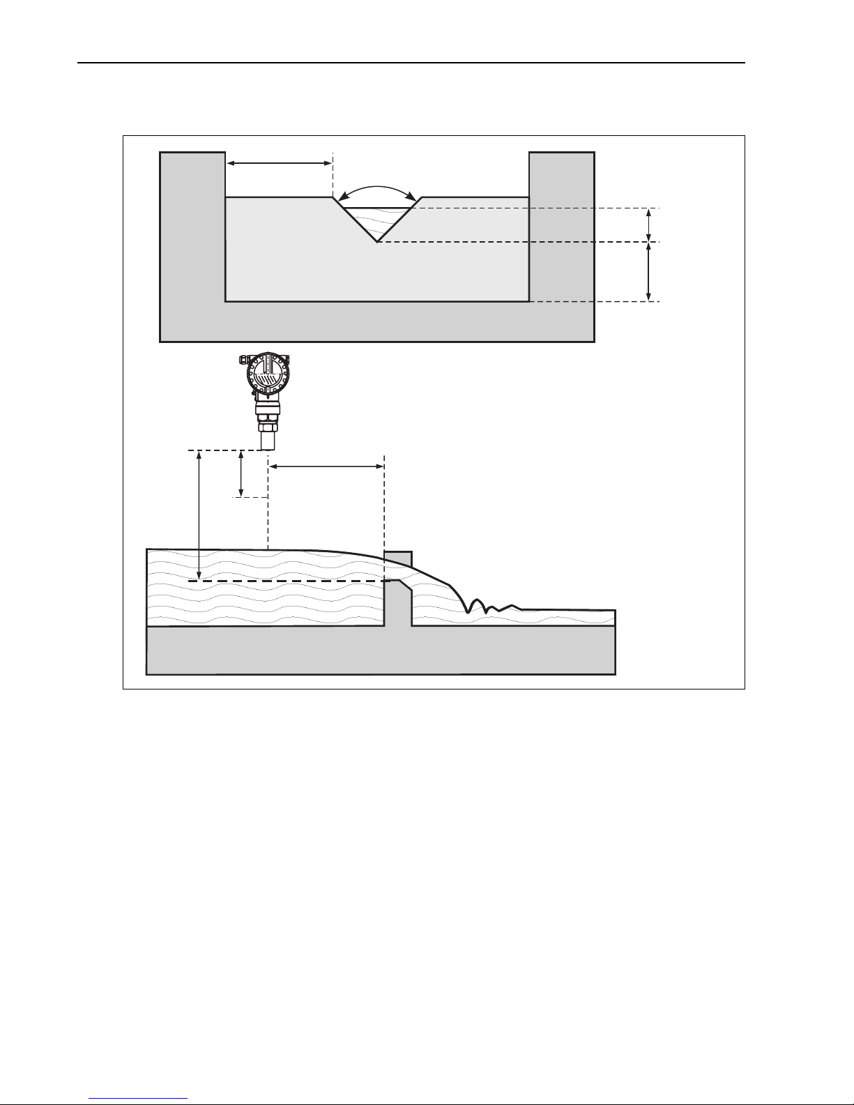
Example: Triangular weir
L00-FMU4xxxx-17-00-00-xx-012
BD Blocking distance
E Empty calibration
F Full calibration
2.4 Measuring range
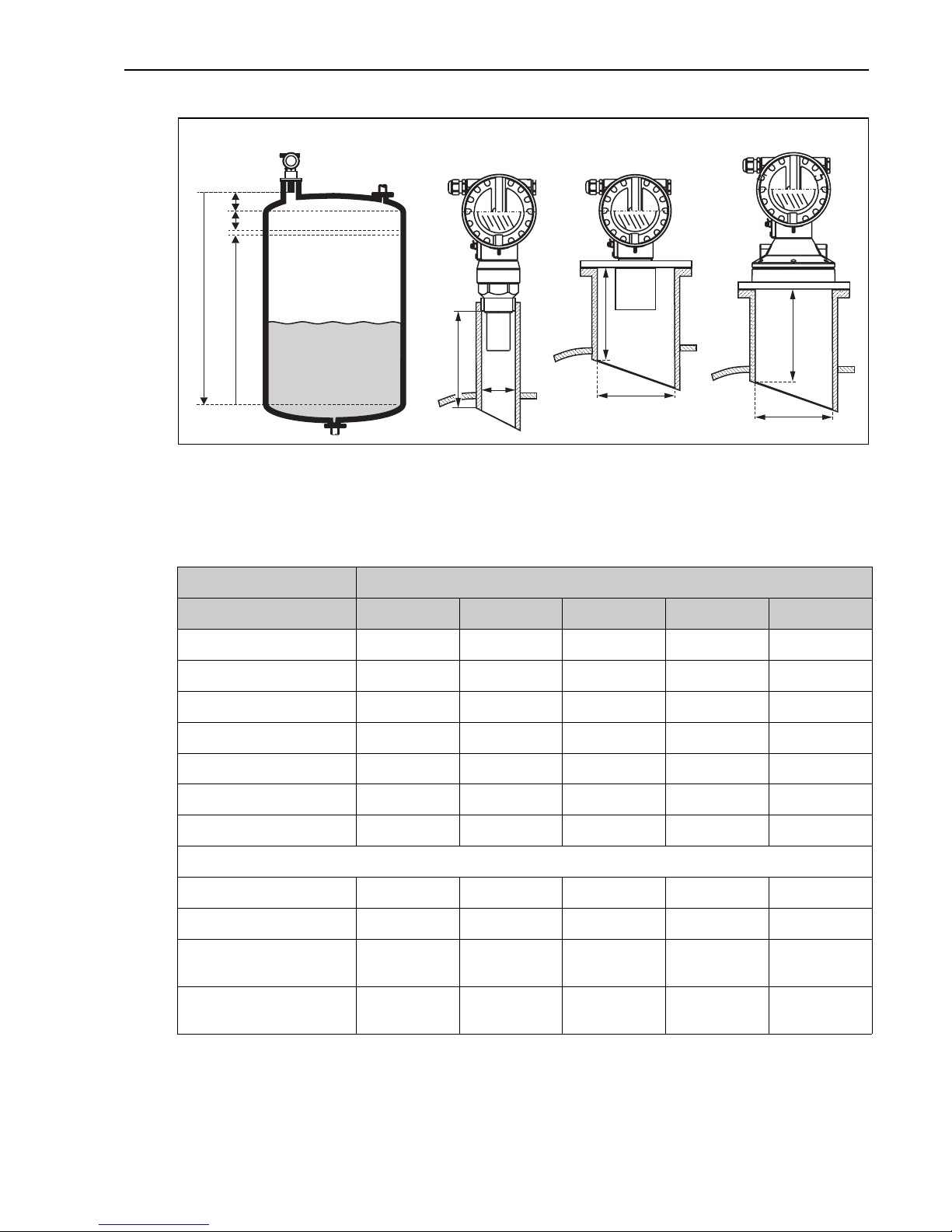
2.4.1 Blocking distance, Nozzle mounting
Install the Prosonic M at a height so that the blocking distance BD is not undershot, even at
maximum fill level. Use a pipe nozzle if you cannot maintain the blocking distance in any other
way. The interior of the nozzle must be smooth and may not contain any edges or welded joints.
In particular, there should be no burr on the inside of the tank side nozzle end. Note the
specified limits for nozzle diameter and length. To minimise disturbing factors, we recommend
an angled socket edge (ideally 45°).
max
max
max
max
(= F)
min. 3 H
H
min. 2 H
a
min. 2 H
BD
E
Prosonic M PROFIBUS PA Mounting
Endress+Hauser 11
L00-FMU4KAxx-17-00- 00-yy-004
BD Blocking distance F Full calibration (span)
SD Safety distance D Nozzle diameter
E Empty calibration L Nozzle length
"
Caution!
If the blocking distance is undershot, it may cause device malfunction.
F
E
BD
SD
L
D
FMU40/41
L
D
FMU43
L
D
FMU42/44
Maximum nozzle length [mm (in)]
Nozzle diameter FMU40 FMU41 FMU42 FMU43 FMU44
DN50/2" 80 (3.15)
DN80/3" 240 (9.45) 240 (9.45) 250 (9.84)
DN100/4" 300 (11.8) 300 (11.8) 300 (11.8) 300 (11.8)
DN150/6" 400 (15.7) 400 (15.7) 400 (15.7) 300 (11.8) 400 (15.7)
DN200/8" 400 (15.7) 400 (15.7) 400 (15.7) 300 (11.8) 400 (15.7)
DN250/10" 400 (15.7) 400 (15.7) 400 (15.7) 300 (11.8) 400 (15.7)
DN300/12" 400 (15.7) 400 (15.7) 400 (15.7) 300 (11.8) 400 (15.7)
Sensor characteristics
Emitting angle α 11° 11° 9° 6° 11°
Blocking distance [m (ft)] 0.25 (0.8) 0.35 (1.1) 0.4 (1.3) 0.6 (2.0) 0.5 (1.6)
Max. range [m (ft)]
in liquids
5 (16.0) 8 (26.0) 10 (33.0) 15 (49.0) 20 (66.0)
Max. range [m (ft)]
in solids
2 (6.6) 3.5 (11.0) 5 (16.0) 7 (23.0) 10 (33.0)
 Loading...