

Endress+Hauser Prosonic FMU 860, Prosonic FMU 862 Technical Information
Technical
Information
TI 190F/00/en
Applications
Prosonic FMU 860...862 ultrasonic
transmitters are for use with the
Prosonic FDU 80...86 family of sensors.
The transmitter determines levels in
silos and tanks and calculates the
volume of solids and liquids they
contain.
With the appropriate certified sensor,
measurements can be made in
explosion hazardous areas, zone 1 or in
combustible dusts.
When used for applications in fresh and
waste-water, Prosonic measures
•
flow rates in flumes and weirs
•
water levels
and can control screen cleaning and
pumps.
Features and Benefits
A customised instrument programme for
the specific application.
Choice of transmitters
•
For the field or control room
•
Single or two-channel versions with
three or five relays, also with optional
totaliser
•
With optional serial interface for
remote configuration (INTENSOR or
HART protocol)
•
With RS-485 interface
Intelligent commissioning, ultrasonic
measurement par excellence
•
Instrument parameters arranged in a
simple matrix
•
Various linearisation functions,
totalisers, and all common Q/h curves
on call
•
Quick commissioning and stable
measurement thanks to signal pattern
recognition by fuzzy logic and the
application parameter
Ultrasonic Measurement
prosonic FMU 860…862
Level and flow measurement with ultrasonics
Simple to start up, easy to use, flexible
Field mounted ultrasonic transmitters
The Prosonic ultrasonic
transmitter in the IP 66
protectivehousing
Hauser
+
Endress
The Power of Know How
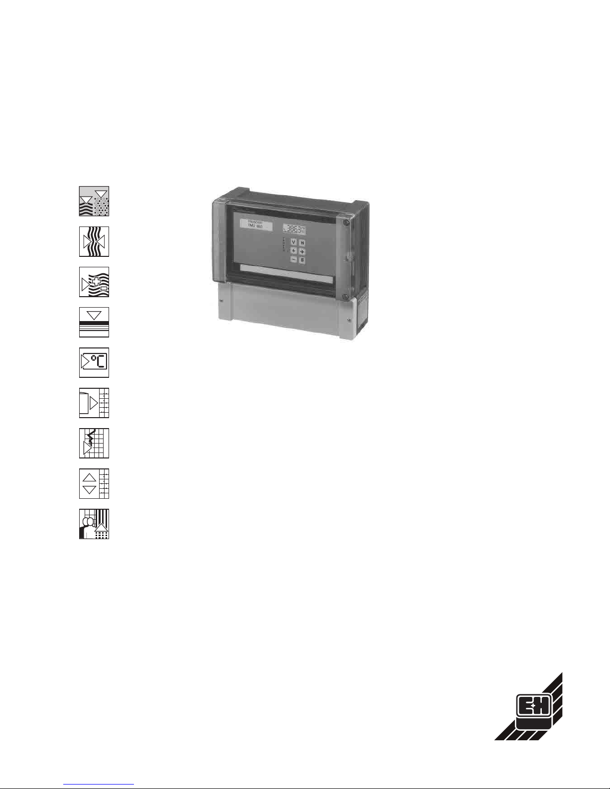
Measuring System
Measuring System
The measuring system consists of the
Prosonic transmitter with a Prosonic
sensor chosen according to the
application at hand. The two-channel
version is for differential measurement
or for controlling two measuring points.
The certified sensor ensures that the
measuring system can be used in
explosion hazardous areas. Other units
can be connected to the Prosonic
transmitter for special applications:
•
separate temperature sensor, e.g. if
the ultrasonic sensor is heated
•
separate external limit detector.
The Prosonic transmitter can be
integrated into automation systems
using the RS-485 interface (see page
5…6).
Transmitters and Applications
Prosonic FMU 860
for continuous level
and volumetric measurement of liquids
and solids in tanks and silos.
Prosonic FMU 861
for flow rate
measurement in flumes and weirs.
Prosonic FMU 862
two-channel version
for:
•
measurement of flow rate or level on
channel 1 and level measurement only
on channel 2 or
•
differential or average measurement
(On request: FMU 862 D version for
distance measurement between two
sensors).
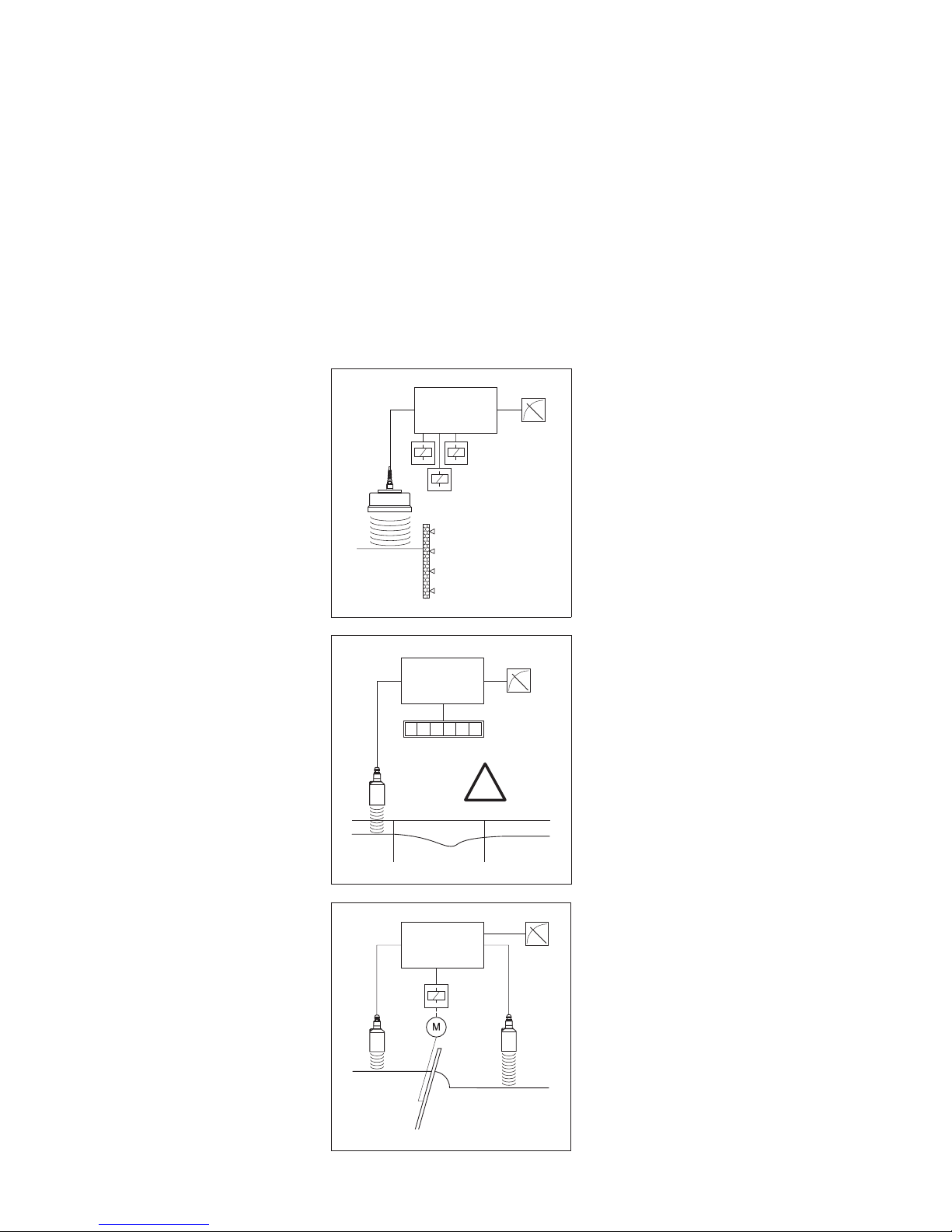
Prosonic FMU 860
Water level measurement, e.g. for
controlling water inflow and outflow, or
for pump control in up to 5 stages. Also:
•
alternating pump control,
•
adjustable switch delay.
Prosonic FMU 861
Flow rate measurement in flumes or
weirs to determine water level with
millimeter accuracy.
The linearisation curves of all common
standard flumes and weirs are preset
and can be called up as required. For
the version with IP 66 housing, the
amount flowing through is summated
and displayed by the totaliser. Also:
•
low flow cut-off,
•
separate display of floodwater on
external counters,
•
sample control using a quantity or time
function.
Prosonic FMU 862
The two-channel unit is used for
differential level measurement, e.g. for
controlling the screen cleaning process
as a function of clogging. Also:
•
superimposed interval timer,
•
trend indication,
•
back water alarm.
Back water in weirs is detected,
signalled and the flowrate automatically
adjusted.
FDU
FMU 860
L
Level
Levelmeasurement for
pump control
EX
FDU
FMU 861
123 4 56
Q
Flow
Ex Zone 1
Flow measurement
FDU
FDU
FMU 862
∆h
Differential
Differential
measurement for
cleaning control
2
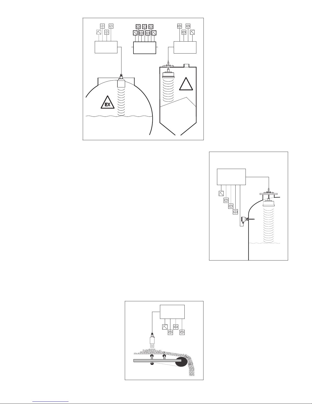
Prosonic FMU 860
Ultrasonic measurement in a silo or
tank. Non-contact level measurement
with no maintenance even under poor
conditions.
Prosonic FMU 862
The two-channel version is especially
cost-effective. When the five relay
version is used to operate two
measuring points, for example, a
maximum and minimum switchpoint can
be allocated to each channel. The alarm
relay signals any abnormal operation.
Prosonic FMU 86…
Double protection against overfill: all
Prosonic transmitters have an additional
connection for an external limit detector.
Even when the level moves within the
blocking distance of the sensor, this is
promptly indicated by the display, the
signal output and relays.
Prosonic FMU 860
Installation on conveyor belts: rapid
changes in load height are easily dealt
with by the Prosonic FMU 860.
FDU
........ ........
StExZone10
FDU
ExZone1
EX
FMU 860 FMU 860 FMU 860
or or
Levelmeasurement in a
tank or a silo.The
FMU 862 two-channel
version is used to
collect data from
individual measuring
points.
FDU
Max.
FMU 86…
All Prosonic transmitters
have an input for an
external limit switch.
FMU 860
FDU
Example of ultrasonic
measurement for
monitoring belt loads
3
Operation and Signal
Processing
Principle of Operation
An ultrasonic pulse emitted from the
sensor is reflected back by the surface
of the material or liquid and is received
by the same sensor as an echo signal.
The product height or water level is then
calculated from the run time of the
ultrasonic signal (echo level
determination).
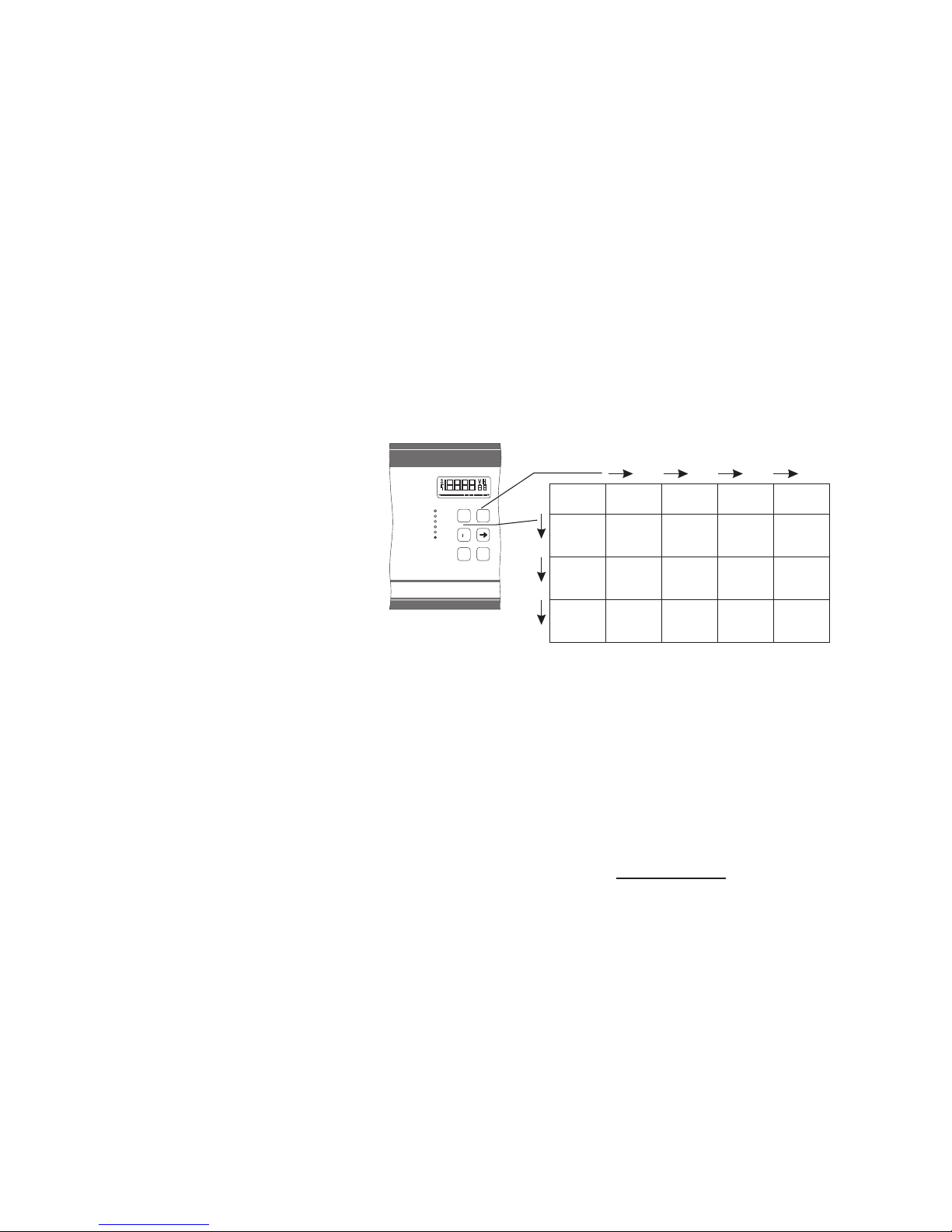
Simple Operation
The keypad on the front panel is used to
configure the transmitter and call up
parameters, which are shown on a 4 1/2
character display.
Input dialogue is based on the standard
Endress+Hauser operating matrix in
which every input field is quickly and
easily selected using the »V« (vertical)
and »H« (horizontal) keys. Parameters
are simply entered using the three keys
»–«, »+«, »➞« and are registered and
stored once the »E« key has been
pressed.
Intelligent Software with Fuzzy
Logic Elements
The Prosonic transmitter is based on
state-of-the-art evaluation methods
including fuzzy logic elements for
intelligent echo analysis. No other
special procedures are required as this
method enables the true level echo to
be clearly distinguished from:
•
sporadic reflections (e.g. from agitator
blades),
•
interference echoes and noise (e.g.
from filling) or
•
multiple reflections (e.g. with closed
tanks).
Even with almost unfavorable mounting
points, the advantages of continuous,
non-contact ultrasonic measurement
can be used by activating a special
fixed target suppression mode or
filtering factor.
Simple Start-Up
The time required for start-up is
minimised by using preset operating
parameter values. Selecting just one
parameter automatically sets the
measuring line to one of five typical
applications.
•
liquid
•
vessels with rapid changes of liquid
•
fine-grained bulk solids
•
coarse-grained bulk solids
•
conveyor belts
Complete Functionality
•
For level measurement
The characteristic curve is already
programmed for volumetric
measurement in a horizontal cylinder.
The linearisation curve of any vessel can
be easily entered (maximum 32 points).
The Prosonic FMU 862 also has a
differential measurement mode
(Value 1 – Value 2)
or average value mode
(Value 1 + Value 2)
2
•
For flow rate measurement
All common Q/h characteristic curves
for measuring flow rates with flumes and
weirs are stored in the Prosonic. Other
Q/h curves can be entered (up to a
maximum of 32 points).
Three different programmable counting
pulses for totalising can be sent to the
relay outputs for controlling external
counters. The transmitter itself has a
resettable software counter: a
non-resettable totaliser is available as
an option.
H
V
+
-
E
Only a fewinput steps are
required for calibrating all
standard applications.
Measured
value
Empty
calibration
Full
calibration
Application Sensor
type
Relay
selection
Relay
function
Switch-on
point
Switch-off
point
Pump
control
Linearisation
Preset
height
Q/h char.
curve
Level Volume
Fixed
target
suppress.
Echo
attenuation
S/N
factor
Warning/
Fault
Output
with
fault
4
Remote Operation
Handheld Terminal
Operating the Prosonic transmitter is
even easier if it is connected via a serial
interface. All values can then be entered
using a handheld terminal. The user has
comprehensive and detailed information
on inputs both on-site and in the control
room. The measurement remains totally
unaffected during the interactive input.
Two different handheld terminals are
available:
•
Commulog VU 260 Z is used with the
serial interface for the INTENSOR
protocol. It can be connected to all
Endress+Hauser instruments with an
INTENSOR protocol.
•
Universal HART communicator via the
serial interface with the HART protocol
(Type C).
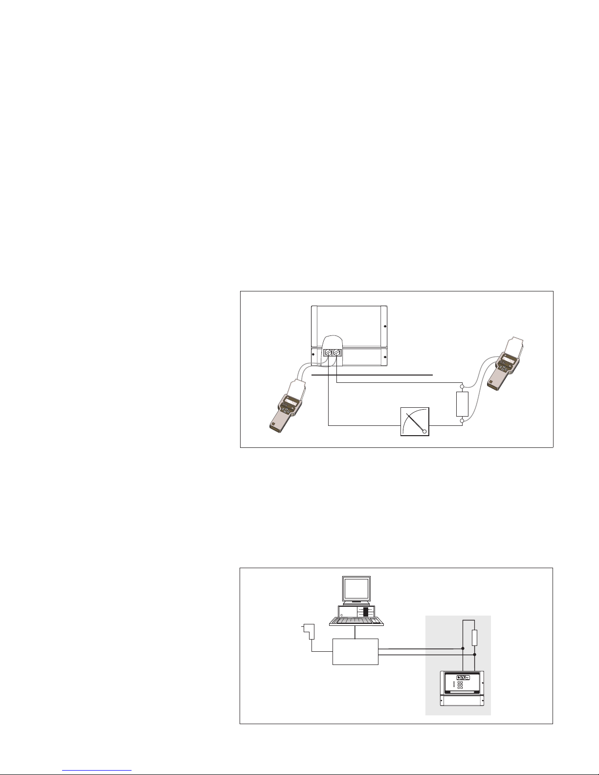
Electrical Connection
A minimum resistance must be present
in the circuit for correct transmission of
the communications signal to take place
(see Technical Data).
The handheld terminal is connected
either
•
directly to current output 1 of the
transmitter or
•
to a communications resistor.
In general: The handheld terminal can
be connected anywhere in the signal
circuit as long as there is a resistance
between its terminals which is larger
than the minimum communications
resistor.
Technical Data
Maximum load: 600 Ω
Communications resistor: 250 Ω
Screened cable recommended,
maximum capacitance 100 nF.
Operation via Commuwin II
The Commubox FXA 191 connects
intrinsically safe Smart transmitters that
have an INTENSOR- or HART protocol
to the RS 232 C serial interface of a
personal computer. This enables the
transmitter to be remotely operated with
the Endress+Hauser Commuwin II
operating program.
-
I-
45
I+
Field
Control room
4…20 mA
Communication
resistor
Connection of handheld
terminals Commulog
VU 260 Z (INTENSOR)
and UniversalHART
Communicator
DXR 271 (HART) in the
field and in the control
room.
-
VH
Commuwin II
Commubox
optional
power pack
4…20 mA
minimum total resistance 250 Ω
RS 232 C
Connecting the
Commubox
5
 Loading...