

Page 1
Installation Instructions
Promass 80F, 83F, 84F Exd
Replacing cover
EA100D/06/a2/01.10
71106936
Determining the correct spare part set
This method is used merely to determine whether the spare part set is suitable for the measuring device. Other conclusions drawn from the table are not applicable.
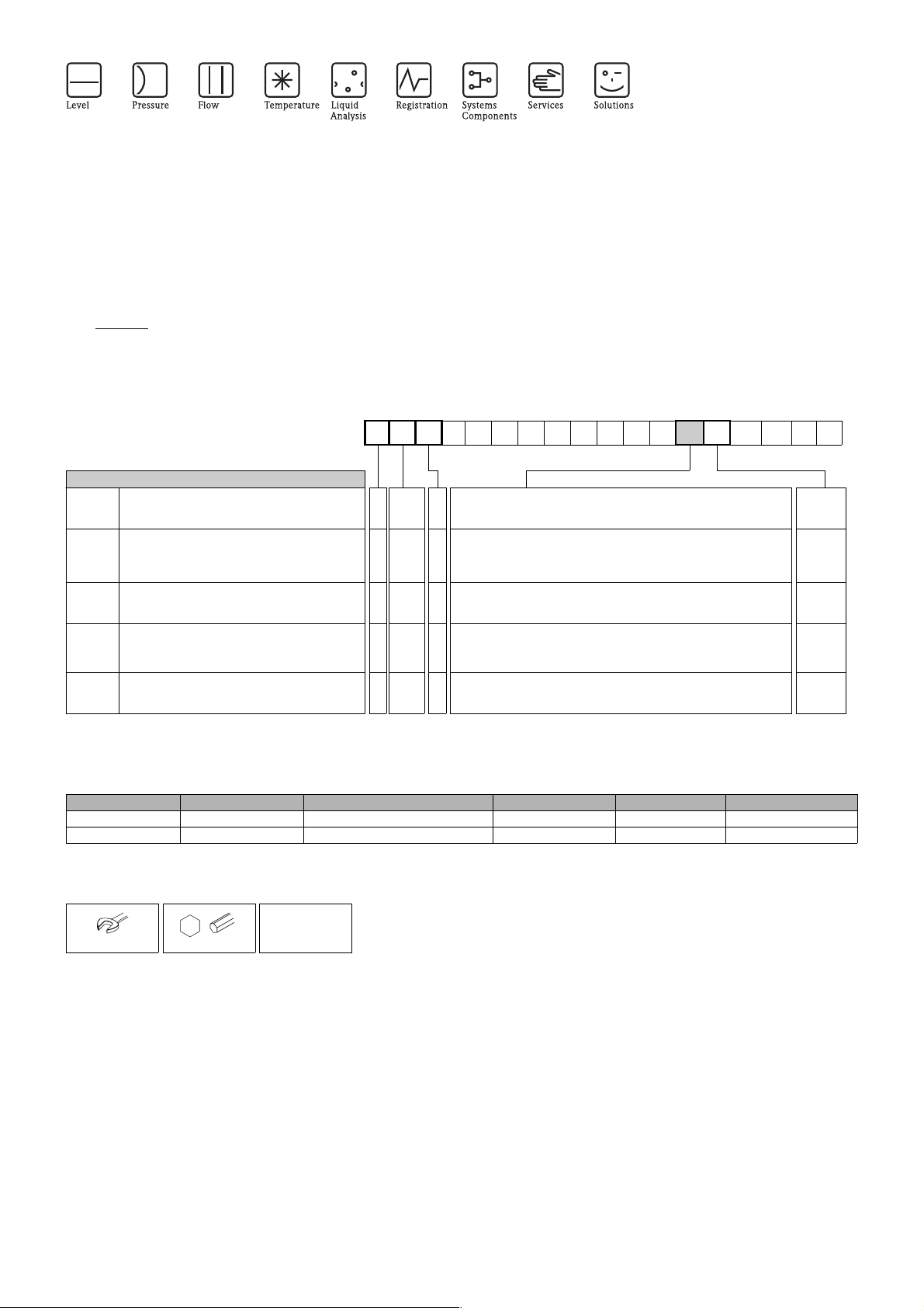
1. Read the order code from the nameplate on the measuring device and enter it in the empty fields below.
2. Select the order number of the spare part set in the table below.
3. Check the fields after the order number selected against the highlighted items in the order code.
4. If each field
(* = no restriction).
after the selected order number contains a digit or letter from the order code, the spare part set can be used for the measuring device
! Note! The number of the spare part set can differ from the material number of the spare part it contains!
The order number of the relevant spare part set can be established by entering the material number of the spare part in the spare parts finder.
We recommend that the Installation Instructions be kept with the packaging at all times.
123456789101112131415161718
Promass 8 F**–****** ****
Order No., Original Spare Part Set
71069283
71069284
71069287
71069288
71069290
Kit cover 8X with window Inox Exd
1 × cover D15 complete Inox with screen Exd
1 × O-Ring 123.4 × 3.53 NBR
Kit Cover clamp Inox
2 × claw
2 × screw M4 × 16
2 × spring washer M4
Kit cover 8X blind version Inox Exd
1 × cover Inox Exd
1 × O-Ring 123.4 × 3.53 NBR
Kit cover 8X terminal compartment Inox Exd
1 × cover Inox Exd
1 × O-Ring 113.90 × 3.53 NBR
1 × Kit cover 8X terminal compartment Inox Exe
1 × cover Inox Exe
1 × O-Ring 113.90 × 3.53 NBR
8 0, 3, 4 F B, C, D, E, F, K, L, M, G, N, O, P, Q, S, T, U, W, 1, 2, 3, 4, 5, 6 L, M, N
8 0, 3, 4 F *
8 0, 3, 4 F B, C, D, E, F, G, K, L, M, N, O, P, Q, S, T, U, W, 1, 2, 3, 4, 5, 6 L, M, N
8 0, 3, 4 F B, C, F, K, L, M, N, O, P, U, W, 1, 3, 4 L, M, N
8 0, 3, 4 F D, E, G, Q, S, T, 2, 5, 6 L, M, N
L, M, N
Determining approval and authorized personnel category:
1. Take the option from the order code field highlighted in gray.
2. Determine the approval and authorized category of personnel using the option in the table.
3. Any person who carries out repairs is responsible for safety during the work, the quality of work completed and safety of the device after repair.
Approval without Approval ATEX II2G, II1/2G, II2D FM/CSA Div. 1 TIIS Zone 1 NEPSI Zone 1
Option "A" "B, C, D, E, F, G, 1, 2, 3, 4, 5" "N, O, P" " U, W" "K, L, M, S, T, Q"
Authorized personnel 1, 2, 3 1, 2, 3 1, 2, 3 1, 2, 3 1, 2, 3
1 = Trained specialist on the customer side, 2 = Service technician authorized by Endress+Hauser, 3 = Endress+Hauser Flowtec AG (send device)
1* = It is recommended that devices with a design approval be repaired by skilled professionals who have been trained by E+H.
Tool List
acid-free,
non-hardening
24 mm 3 mm
grease
Page 2
Replacing cover Promass 80F, 83F, 84F Exd
1 Safety Instructions
• Comply with national regulations governing mounting, electrical installation,
commissioning, maintenance and repair procedures. (Available sources,
e.g. series of standards IEC 60364 and IEC 60079-14/-17/-19).
• Requirements with regard to specialized technical staff for the mounting,
electrical installation, commissioning, maintenance and repair of the
measuring devices: trained in instrument safety
– familiar with the individual protection concepts of the devices
– for Ex-certified measuring devices: also trained in explosion protection
• The spare parts set and Installation Instructions are used to replace a faulty unit
with a functioning unit of the same type.
Use genuine parts from Endress+Hauser only.
• Using the material number and identification information, check whether the
spare part matches the identification label on the measuring device.
• If you have any questions, contact your E+H service organization.
• Modifications of the measuring device are not permitted.
• Follow all measuring device documentations.
• In the case of Ex-certified measuring devices: Comply with the operating and
installation instructions and operating conditions in the supplementary
Ex-documentation.
• Hot surfaces! Risk of injury!
Before commencing work, allow the system and measuring device to cool
down to a touchable temperature.
• In the case of measuring devices in custody transfer applications, the custody
transfer status no longer applies once the lead seal has been removed.
• In the case of measuring devices in safety-related applications in accordance
with EN 61508 or EN 61511, reconfigure and test following any repair.
Document the repair procedure in accordance with the applicable standard(s).
• In the case of Ex-certified measuring devices: Only open in a de-energized
state (once a delay of 10 minutes has elapsed after switching off the power
supply) or in environments which do not have a potentially explosive
atmosphere.
• After removing the electronics cover, there is a risk of electric shock as shock
protection is removed!
Switch off the measuring device before removing internal covers.
• Service connector:
– do not connect in potentially explosive atmospheres.
– only connect to Endress+Hauser service devices.
• Only open housing for a brief period. Avoid the penetration of foreign bodies,
moisture or contaminants.
• To regain the (explosion) protection of the measuring device:
– seal the openings with genuine covers
– seal cable entries with approved components suitable for the (explosion)
protection.
• Replace defective seals/gaskets by genuine parts from Endress+Hauser only.
• Threads (e.g. of the cover for the electronics and connection compartments)
must be lubricated. Use an acid-free, non-hardening grease if an abrasion
resistant dry lubricant is non-existent.
• If threads are damaged or defective, the measuring device must be repaired.
• If spacing is reduced or the dielectric strength of the measuring device cannot
be guaranteed during repair work, perform a test on completion of the work
(e.g. high-voltage test in accordance with the manufacturer's instructions).
• Observe the instructions for transporting and returning the device outlined in
the Operating Instructions.
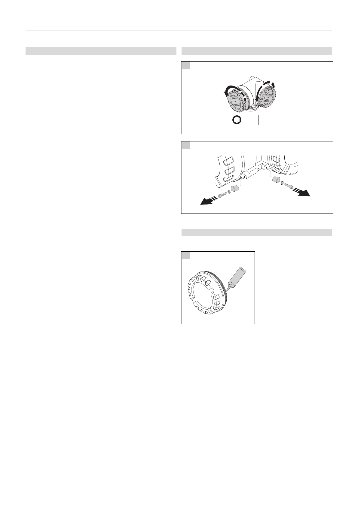
2 Replacing cover with O-Ring and claw
a
3mm
A0012820
b
A0012822
3Re-assembly
Re-assembly is carried out in reverse order, unless otherwise instructed.
The following must be noted:
a
A0011687
Endress+Hauser 2
Page 3
Einbauanleitung
Promass 80F, 83F, 84F Exd
Austausch Deckel
EA100D/06/a2/01.10
71106936
Ermitteln des zulässigen Ersatzteilsets
Diese Methode dient nur zur Überprüfung, ob Ersatzteilset und Messgerät zueinander passen. Andere aus der Tabelle gezogene Schlussfolgerungen sind nicht gültig.
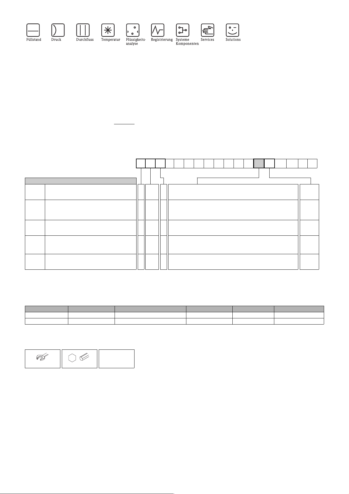
1. Bestellcode auf dem Typenschild des Messgeräts ablesen und unten in die leeren Felder eintragen.
2. In der nachfolgenden Tabelle die Bestellnummer des Ersatzteilsets heraussuchen.
3. Die Felder hinter der ermittelten Bestellnummer mit den hervorgehobenen Positionen im Bestellcode abgleichen.
4. Wenn hinter der ermittelten Bestellnummer jedes Feld
verwendet werden (* = keine Einschränkung).
eine Ziffer oder einen Buchstaben aus dem Bestellcode enthält, kann das Ersatzteilset für das Messgerät
! Hinweis! Die Nummer des Ersatzteilsets kann von der Materialnummer des enthaltenen Ersatzteiles abweichen!
Durch Eingabe der Materialnummer des Ersatzteiles im Ersatzteilfindetool kann die Bestellnummer des entsprechenden Ersatzteilsets ermittelt werden.
Wir empfehlen Einbauanleitung und Verpackung immer zusammen aufzubewahren.
123456789101112131415161718
Promass 8 F**–****** ****
Bestellnummer, Original Ersatzteil-Set
71069283
71069284
71069287
71069288
71069290
Set Deckel 8X mit Fenster Inox Exd
1 × Deckel komplett Inox mit Glas Exd
1 × O-Ring 123,4 × 3,53 NBR
Set Deckelkralle Inox
2 × Kralle
2 × Schraube M4 × 16
2 × Federring M4
Set Deckel 8X Blindversion Inox Exd
1 × Deckel Inox Exd
1 × O-Ring 123,4 × 3,53 NBR
Set Deckel 8X Anschlussklemme Inox Exd
1 × Deckel Inox Exd
1 × O-Ring 113,90 × 3,53 NBR
1 × Set Deckel 8X Anschlussklemme Inox Exe
1 × Deckel Inox Exe
1 × O-Ring 113,90 × 3,53 NBR
8 0, 3, 4 F B, C, D, E, F, K, L, M, G, N, O, P, Q, S, T, U, W, 1, 2, 3, 4, 5, 6 L, M, N
80, 3, 4 F *
8 0, 3, 4 F B, C, D, E, F, G, K, L, M, N, O, P, Q, S, T, U, W, 1, 2, 3, 4, 5, 6 L, M, N
8 0, 3, 4 F B, C, F, K, L, M, N, O, P, U, W, 1, 3, 4 L, M, N
8 0, 3, 4 F D, E, G, Q, S, T, 2, 5, 6 L, M, N
L, M, N
Ermitteln von Zulassung und reparaturberechtigtem Personenkreis:
1. Im grau unterlegten Bestellcodefeld die Option entnehmen.
2. Mit Hilfe der Option in der Tabelle Zulassung und den befähigten Personenkreis ermitteln.
3. Jegliche Person, welche eine Reparatur vornimmt, übernimmt die Verantwortung für die Sicherheit während der Arbeiten, die Qualität der Ausführung und die
Sicherheit des Geräts nach der Reparatur.
Zulassung Ohne Zulassung ATEX II2G, II1/2G, II2D FM/CSA Div. 1 TIIS Zone 1 NEPSI Zone 1
Option "A" "B, C, D, E, F, G, 1, 2, 3, 4, 5" "N, O, P" " U, W" "K, L, M, S, T, Q"
Befähigung 1, 2, 3 1, 2, 3 1, 2, 3 1, 2, 3 1, 2, 3
1 = Ausgebildete Fachkraft des Kunden, 2 = von Endress+Hauser autorisierter Servicetechniker, 3 = Endress+Hauser Flowtec AG (Gerät einsenden)
1* = Es wird empfohlen, Reparaturen welche an Geräten mit Bauartzulassung vorgenommen werden, von ausgebildeten Fachleuten durchführen zu lassen, die von E+H geschult wurden.
Werkzeugliste
Säurefreies,
nicht härtendes
24 mm 3 mm
Fett
Page 4
Promass 80F, 83F, 84F Exd Austausch Deckel
1 Sicherheitshinweise
• Nationale Vorschriften bezüglich der Montage, elektrischen Installation,
Inbetriebnahme, Wartung und Reparatur einhalten. (Mögliche Quellen
z.B. Normenreihe IEC 60364 und IEC 60079-14/-17/-19).
• Anforderungen an das Fachpersonal für Montage, elektrische Installation,
Inbetriebnahme, Wartung und Reparatur der Messgeräte:
– in Gerätesicherheit ausgebildet
– mit den jeweiligen Schutzkonzepten der Geräte vertraut
– bei Ex-zertifizierten Messgeräten: zusätzlich im Explosionsschutz
ausgebildet
• Ersatzteilset und Einbauanleitung dienen dazu, eine defekte Einheit gegen
eine funktionierende Einheit des gleichen Typs zu ersetzen.
Nur Originalteile von Endress+Hauser verwenden.
• Anhand von Materialnummer und Kennzeichnung prüfen, ob das vorliegende
Ersatzteil zur Kennzeichnung auf dem Messgerät passt.
• Bei Fragen: Kontaktieren Sie Ihre zuständige E+H-Serviceorganisation.
• Änderungen am Messgerät sind nicht zulässig.
• Dokumentation zum Messgerät beachten.
• Bei Ex-zertifizierten Messgeräten: Installationsvorschriften und
Einsatzbedingungen aus der Ex-Zusatzdokumentation einhalten.
• Verbrennungsgefahr durch heiße Oberflächen!
Vor Arbeitsbeginn: Anlage und Messgerät auf berührungssichere Temperatur
abkühlen.
• Bei Messgeräten im abrechnungspflichtigen Verkehr: Nach Entfernen der
Plombe ist der geeichte Zustand aufgehoben.
• Bei Messgeräten in sicherheitstechnischen Applikationen gemäß EN 61508
bzw. EN 61511: Nach Reparatur neu einstellen und testen. Die Reparatur
normkonform dokumentieren.
• Bei Ex-zertifizierten Messgeräten: Nur in spannungslosen Zustand (nach
Berücksichtigung einer Wartezeit von 10 Minuten nach Abschalten der
Energiezufuhr) oder in Umgebungen öffnen, die keine explosionsfähige
Atmosphäre enthalten.
• Nach Entfernen der Elektronikabdeckung: Stromschlaggefahr durch
aufgehobenen Berührungsschutz!
Messgerät ausschalten, bevor interne Abdekkungen entfernt werden.
• Servicestecker:
– nicht in explosionsfähiger Atmosphäre anschließen.
– nur an Servicegeräte von Endress+Hauser anschließen.
• Gehäuse nur kurzzeitig öffnen. Eindringen von Fremdkörpern, Feuchtigkeit
oder Verunreinigung vermeiden.
• Um die (Zünd-) Schutzart des Messgeräts wieder herzustellen:
– Öffnungen mit Originaldeckeln verschließen
– Kabeleinführungen mit zugelassenen, der (Zünd-)Schutzart angepassten
Komponenten verschließen.
• Defekte Dichtungen nur durch Originaldichtungen von Endress+Hauser
ersetzen.
• Gewinde (z. B. von Elektronikraum- und Anschlussraumdeckel) müssen
geschmiert sein. Säurefreies, nicht härtendes Fett verwenden, sofern keine
abriebfeste Trockenschmierung vorhanden ist.
• Defekte Gewinde erfordern eine Instandsetzung des Messgeräts.
• Wenn bei den Reparaturarbeiten Abstände reduziert oder die
Spannungsfestigkeit des Messgeräts nicht sichergestellt werden kann: Prüfung
nach Abschluss der Arbeiten durchführen (z.B. Hochspannungstest gemäß
Herstellerangaben).
• Transport- und Rücksendungshinweise in der Betriebsanleitung beachten.
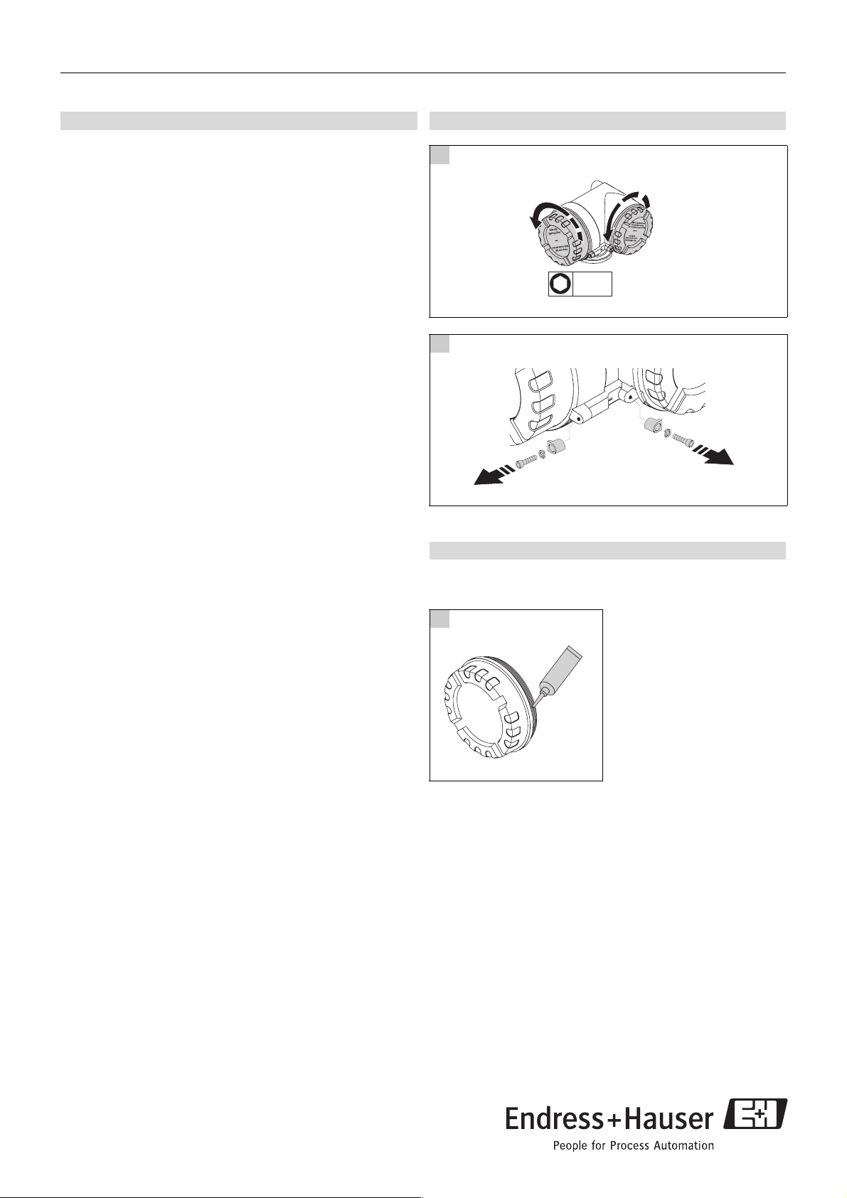
2 Austausch Deckel mit O-Ring und Deckelkralle
a
3mm
A0012820
b
A0012822
3 Zusammenbau
Der Zusammenbau erfolgt in umgekehrter Reihenfolge, wenn nicht anders
angegeben.
Folgendes ist zu beachten:
a
A0011687
 Loading...