

Endress+Hauser PROMAG 33 Operating Manual
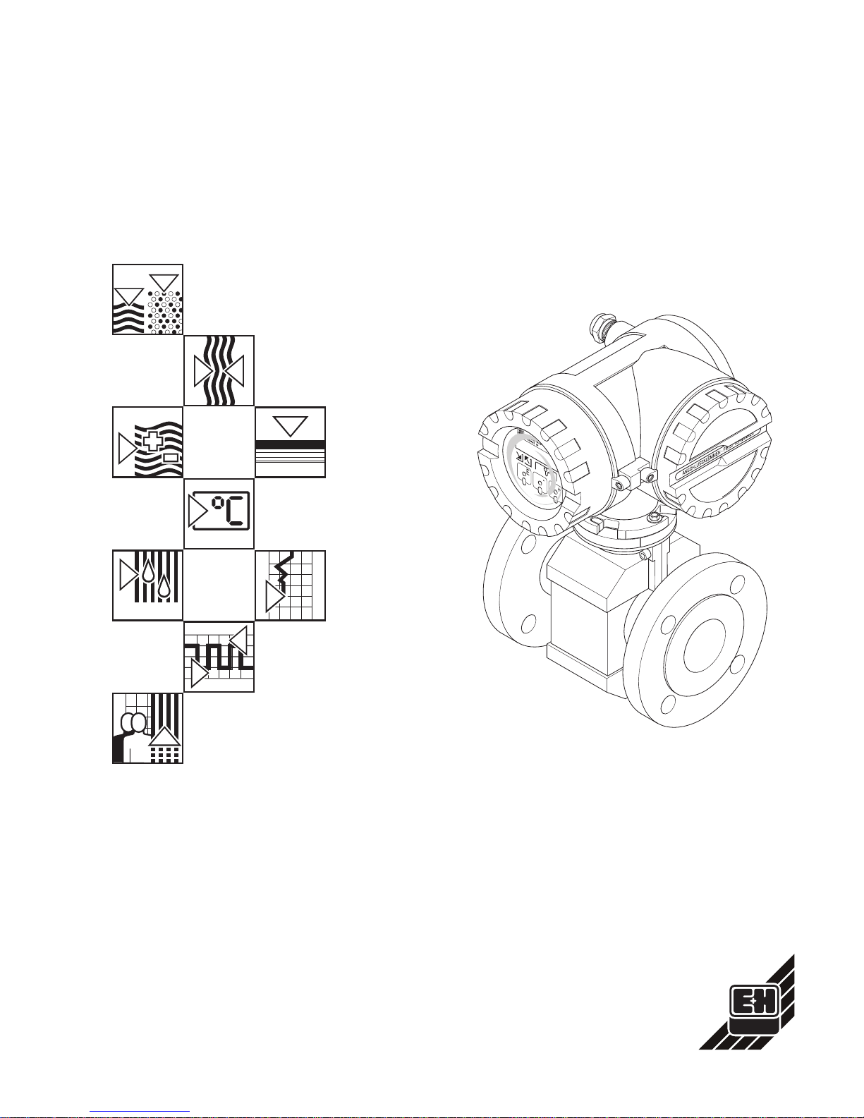
promag 33
Electromagnetic
Flow Measuring System
Operating Manual
Hauser+Endress
Nothing beats know-how
BA 009D/06/en/04.99
No. 50063718
CV 5.0
Valid as of software version
V 3.01.XX (amplifier)
V 2.04.XX (communication)

Brief Operating Instructions
With the following instructions, you may configure your measuring instrument quickly
and easily:
Safety instructions → see page 5
↓
Mounting and electrical connection
• Mounting → see page 9
• Electrical connections → see page 21
↓
Commissioning → see page 34
↓
Operation → see page 35 ff.
↓
Display configuration
• Language → see page 68
• Contrast → see page 68
• Assign line 1 → see page 67
• Assign line 2 → see page 67
• Number of decimal digits → see page 68
continued: next column
ba009y83
Engineering units → see page 47 ff.
↓
Configuration of outputs
Current output
• Full scale values → see page 49, 51
• Current span → see page 51
Pulse / Frequency output
• Operation mode → see page 53
• Pulse value → see page 53
• Pulse width → see page 53
• Full scale frequency → see page 54
• Full scale value → see page 55
• Output signal → see page 56
↓
Relay outputs → see page 58 ff.
↓
More complex applications
require programming of additional functions.
The appropriate key works and crossreferences are found on the following pages:
• Functions at a Glance → see page 117
• Index → see page 121
• Operating matrix → see page 37
↓
For optimum measuring results
• Creep suppression → see page 72
• Empty Pipe Detection → see page 73
Promag 33
2 Endress+Hauser

Contents
1 Safety Instructions . . . . . . . 5
1.1 Correct usage . . . . . . . . . . . 5
1.2 Dangers and notes . . . . . . . . . 5
1.3 Personnel for installation, start-up and
operation . . . . . . . . . . . . 6
1.4 Repairs and dangerous substances . . 6
1.5 Technical improvements . . . . . . . 6
2 Instrument Identification . . . . 7
3 Mounting and Installation . . . . 9
3.1 Transport instructions (DN ≥ 350/14") . . 9
3.2 Mounting location . . . . . . . . 10
3.3 Mounting position . . . . . . . . . 12
3.4 Nominal diameter and flow rate . . . . 13
3.5 Adapters . . . . . . . . . . . . 14
3.6 Mounting Promag A sensor . . . . . 15
3.7 Mounting Promag H sensor . . . . 16
3.8 Mounting Promag F sensor . . . . . 17
3.9 Turning the transmitter housing
and local display . . . . . . . . . 19
3.10 Mounting the transmitter (remote version) 20
4 Electrical Connection . . . . . 21
4.1 Degree of protection . . . . . . . . 21
4.2 Connecting the transmitter . . . . . . 22
4.3 Connecting the cable of the remote
version . . . . . . . . . . . . . 25
4.4 Cable specifications . . . . . . . . 27
4.5 Potential equalisation . . . . . . . 28
4.6 Connecting E+H Rackbus
and Rackbus RS 485 . . . . . . . . 30
4.7 Connecting HART Communicator . . . 33
4.8 Connecting Commubox FXA 191
(Commuwin II software) . . . . . . . 33
4.9 Commissioning . . . . . . . . . . 34
5 Display and Operation . . . . . 35
5.1 Display and operating elements . . 35
5.2 Operation (operating matrix) . . . . . 36
5.3 Operating example . . . . . . . . 39
5.4 Operation with the HART protocol . . . 40
5.5 Operating Rackbus RS 485 . . . . . 42
6 Description of Functions . . . . 47
7 Trouble-shooting, Maintenance
and Repairs . . . . . . . . . . 85
7.1 Response of the measuring system
on faults or alarm . . . . . . . . . 85
7.2 Trouble-shooting and remedy . . . . 87
7.3 Error, alarm and status messages . . 90
7.4 Replacing the measuring electrodes . 94
7.5 Replacing the transmitter electronics . 96
7.6 Replacing the fuse . . . . . . . . 97
7.7 Repairs . . . . . . . . . . . . 97
7.8 Spare parts . . . . . . . . . . 97
7.9 Maintenance . . . . . . . . . . . 97
8 Dimensions . . . . . . . . . . 99
8.1 Dimensions Promag 33 A . . . . 99
8.2 Dimensions Promag 33 H . . . . 102
8.3 Dimensions Promag 33 F
(DN 15...300) . . . . . . . . . 104
8.4 Dimensions Promag 33 F
(DN 350...2000) . . . . . . . . 105
9 Technical Data . . . . . . . . 107
10 Functions at a Glance . . . . . 117
11 Index . . . . . . . . . . . . 121
Promag 33
Endress+Hauser 3

RegisteredTrademarks
KALREZ
®
, VITON®and TEFLON
®
Registered trademarks of E.I. Du Pont de Nemours & Co., Wilmington, USA
TRI-CLAMP
®
, HASTELLOY
®
Registered trademarks of Ladish & Co., Inc., Kenosha, USA
Promag 33
4 Endress+Hauser
1 Safety Instructions
1.1 Correct usage
• The Promag 33 measuring system is only to be used for measuring the flow of
conductive fluids. Most liquids can be measured provided they have a minimum
conductivity of ≥ 5 µS/cm, e.g.
– acids, alkalis, pastes, pulps,
– drinking water, wastewater, sewage sludge,
– milk, beer, wine, mineral water, yoghurt, molasses, etc.
A minimum conductivity of ≥ 20 µS/cm is required for measuring demineralised
water.
• The manufacturer assumes no liability for damage caused by incorrect use of the
instrument.
• Instruments which are used in the explosion hazardous area are supplied with a
separate “Ex documentation”, which is an
integral part
of this Operating Manual.
The instructions and connected loads provided in this supplement must absolutely
be observed. An appropriate icon is shown on the front of this document according
to the approval given and the test center (fEurope,hUSA,gCanada).
1.2 Dangers and notes
All instruments are designed to meet state-of-the-art safety requirements, have been
tested, and have left the factory in an operational perfectly safe condition.
The devices were developed according to EN 61010 “Protection Measures for
Electronic Equipment for Measurement, Control, Regulation and Laboratory
Procedures”.
A hazardous situation may occur if the flowmeter is not used for the purpose it was
designed for or is used incorrectly. Please carefully note the information provided in
this Operating Manual indicated by the following pictograms:
Warning!
A “warning” indicates actions or procedures which, if not performed correctly, may
lead to personal injury or a safety hazard.
Please strictly observe the instructions supplied and proceed carefully.
Caution!
A “caution” indicates actions or procedures which, if not performed correctly, may
lead to faulty operations or the destruction of the instrument.
Please strictly observe the respective instructions.
Note!
A “note” indicates actions or procedures which, if not performed correctly, may
indirectly affect operations or lead to an unexpected instrument response.
Warning!
Caution!
Note!
Promag 33 1 Safety Instructions
Endress+Hauser 5
1.3 Personnel for installation, start-up and operation
• Mounting, electrical installation, start-up and maintenance of the instrument may
only be carried out by trained personnel authorised by the operator of the facility.
Personnel must absolutely and without fail read and understand this Operating
Manual before carrying out its instructions.
• The instrument may only be operated by personnel who are authorised and trained
by the operator of the facility. All instructions in this manual are to be observed
without fail.
• With special fluids, incl. those used for cleaning, E+H will be pleased to supply
information concerning the chemical resistance properties of wetted parts.
• When welding the piping, the welding machinery must not be grounded through
the Promag.
• The installer has to make sure that the measuring system is correctly wired up
according to the wiring diagrams. The measuring system is to be grounded.
• Please observe all provisions valid for your country and pertaining to the opening
and repairing of electrical devices.
1.4 Repairs and dangerous substances
The following procedures must be carried out before a Promag 33 is sent to
Endress+Hauser for repair:
• A note must always be enclosed with the instrument, containing a description of the
fault, the application, and the chemical and physical properties of the product being
measured.
• Remove all residue which may be present. Pay special attention to the gasket
grooves and crevices where fluid may be present. This is especially important if
the fluid is dangerous to health, e.g. corrosive, carcinogenic, radioactive, etc.
• No instrument should be returned without all dangerous material being
removed first (e.g. in scratches or diffused through plastic).
Incomplete cleaning of the instrument may result in waste disposal or cause harm to
personnel (burns, etc). Any costs arising from this will be charged to the operator of
the instrument.
1.5 Technical improvements
The manufacturer reserves the right to modify technical data without prior notice.
Your local E+H Sales Office will supply you with all current information and any
updates to this Operating Manual.
Danger of electrical shock!
With the housing cover removed, protection against accidental contact is no
longer present.
Warning!
1 Safety Instructions Promag 33
6 Endress+Hauser
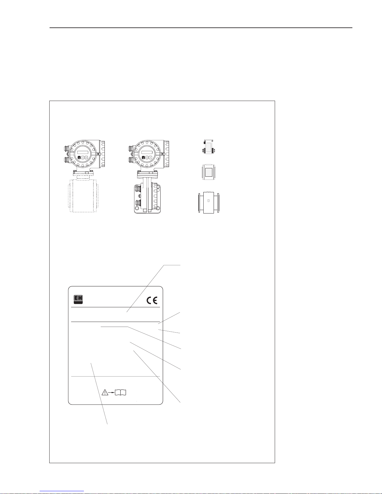
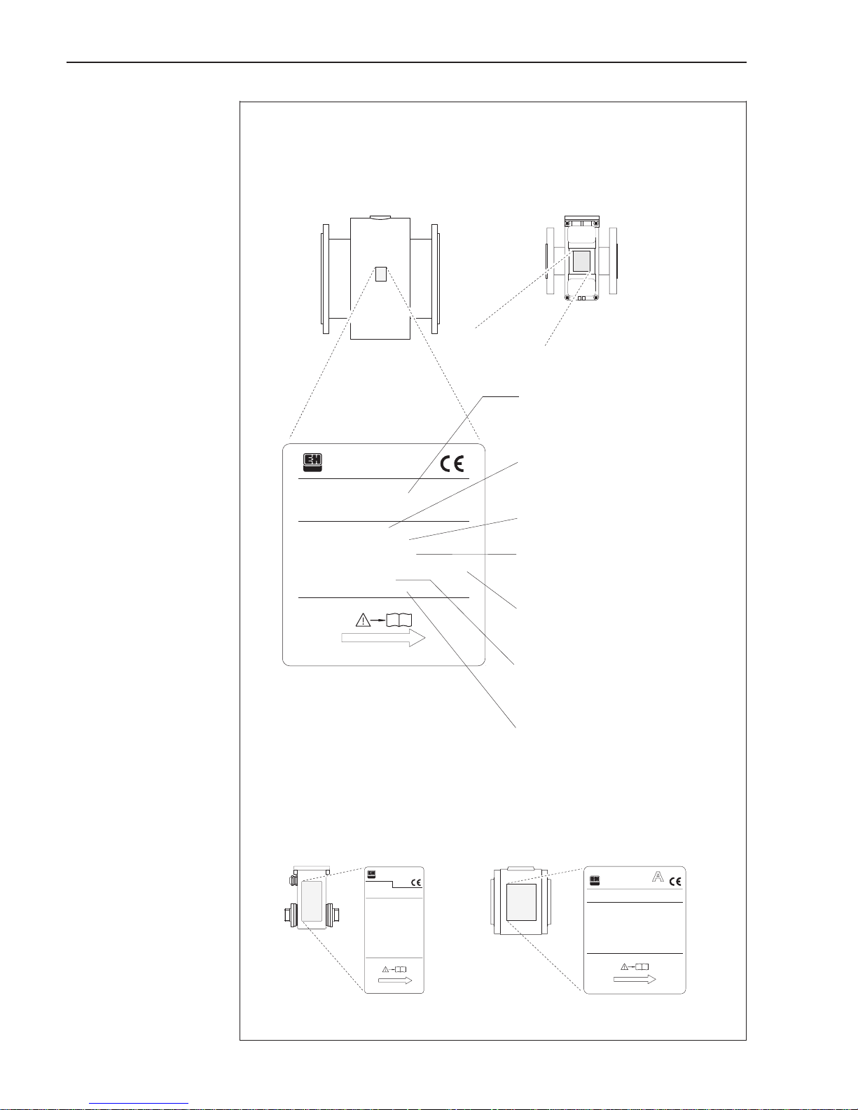
2 Instrument Identification
An overview of the complete Promag 33 measuring system is shown below.
The technical specifications are stamped on the nameplate and contain the following
information:
Pat.219,725 UK (EP) Pat.4,704,908 US
Pat.4,382,387 USPat.2084740 UK
Order Code:
Ser.No.:
ENDRESS+HAUSER
PROMAG
2X 123456
33FT50-AD1AA12A21F
85-260VAC
50-60Hz
EPD/MSÜ ECC 5P-CAL
I-OUT (HART), FREQ-OUT
SONDERPRODUKTE
33
15VA/W
IP 67
i
ba009y03
Order code / Serial number
Definition code: see specifications
on order confirmation
Powerconsumption
15 VA / W
Ingress protection (IP 67)
Powersupply / frequency
85...260 V AC (50...60 Hz)
Additional information
– EPD/MSÜ: with Empty Pipe Detection
– ECC: with Electrode Cleaning Circuitry
– 5P-CAL: with 5-point calibration
Outputs
I-OUT: with current output (HART)
FREQ-OUT: with pulse/frequency output
Special products
Additional information, specifications
Promag 33 transmitter
Promag A
Promag H
Promag F
Sensors
(see next page)
Remote versionCompact version
(example for Promag H)
Fig. 1
Promag 33 transmitter
Typical nameplate specifications
(example)
Promag 33 2 Instrument Identification
Endress+Hauser 7
Pat.US4,382,387 4,704,908 Pat.UKEP 219,725 2,084,740
TM max.:
Pat.US5,323,156 5,351,554
Ser.No.:
Order Code:
K-factor:
Werkstoffe:
Materials:
ENDRESS+HAUSER
PROMAG H
28- 03
33HP1H-ACABA53A21F
2X 123456
0.5328/-5
DN100 / 4"
TUBE/ROHR:OD/SMS/JIS/ISO
PFA1.4435EPDM
150°C IP 67
EPD/MSÜ FS ECC
SONDERPRODUKTE
Pat.US 4,382,387 4,704,908
Pat.UK 2084740 219,725 (EP)
Materials:
Werkstoffe:
Order Code:
Ser.No.:
K-factor:
TM :
max.
ENDRESS+HAUSER
PROMAG F
2X 123456
33FH4H-DD1BA43A21A
0.5328/-5
DN 400 DIN PN10
HG 1.4435
120°C
EPD/MSÜ R/B FS
SONDERPRODUKTE
IP67
i
i
Pat.219,725 UK (EP)
Pat.2084740 UK
Pat.4,704,908US
Pat.4,382,387US
Materials:
Werkstoffe:
Ser.No.:
K-factor:
TM :
max.
PROMAGA
OrderCode:
ENDRESS+HAUSER
2X 123456
33AT25-AH1BA41A21F
0.5328/-5
DN8 1.4435PN40
PFAHAST-C V
130°C
EPD/MSÜ R/B FS ECC
SONDERPRODUKTE
IP67
i
®
3
ba009y04
Promag A, H and F sensors
Promag A (DN 2...25) Promag H (DN 25...100)
Promag F (15...2000) (DN 15...300)
Order code / Serial number
Definition code: see specifications
on order confirmation
Calibration factor / Zero point
0.5328 / –5
Nominal diameter (DN 400)
Pressure rating (DIN PN 10 bar)
Materials
– Lining: hard rubber (HG)
– Measuring electrodes: stainless steel
1.4435
Ingress protection (IP 67)
Max. fluid temperature (120 °C)
Additional information
– EPD/MSÜ: with Empty Pipe Detection
– R/B: with reference electrode
– FS: remote version (see page 20)
Special product
Additional information, specifications
Fig. 2
Promag A, H and F sensors
Typical nameplate specifications
(example)
2 Instrument Identification Promag 33
8 Endress+Hauser
3 Mounting and Installation
Warning!
• The instructions given in this section are to be observed at all times in order to
ensure safe and reliable operation of the measuring system.
• For explosion protected instruments the mounting regulations and the technical
data may differ from those stated here. Please refer to the Ex supplement of this
Operating Manual for additional information.
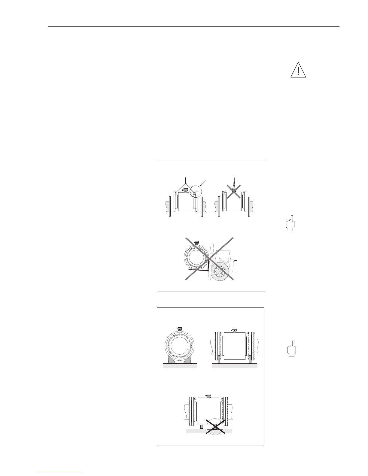
3.1 Transport instructions (DN ≥ 350/14")
The pipe lining on the flanges is protected by disks to prevent damage when
transporting to the measuring point. These are to be removed when installing.
Instruments are to be transported in the containers they are delivered in.
Transporting to the measuring point
• The sensor must not be lifted by the
transmitter housing!
• Use only the grips on the flange for
lifting out and mounting the sensor in
the piping (from DN 350 or 14").
Caution!
The sensor must not be lifted by the
metal casing using a fork lift truck!
This can buckle the casing and so
damage the internal magnetic coils.
Base and supports
The sensor is to be mounted on a base
which is sufficiently strong enough to
withstand its weight.
Caution!
Do not support the sensor by the sheet
casing. The casing may be dented and
so damage the magnetic coils inside
the sensor.
Warning!
Caution!
Caution!
ba009y07
Correct! Incorrect!
Fig. 3
Transport instructions for large
diameter sensors (DN
≥
350)
ba009y08
Correct!
Incorrect!
Fig. 4
The proper way to support large
diameter sensors (DN
≥
350)
Promag 33 3 Mounting and Installation
Endress+Hauser 9
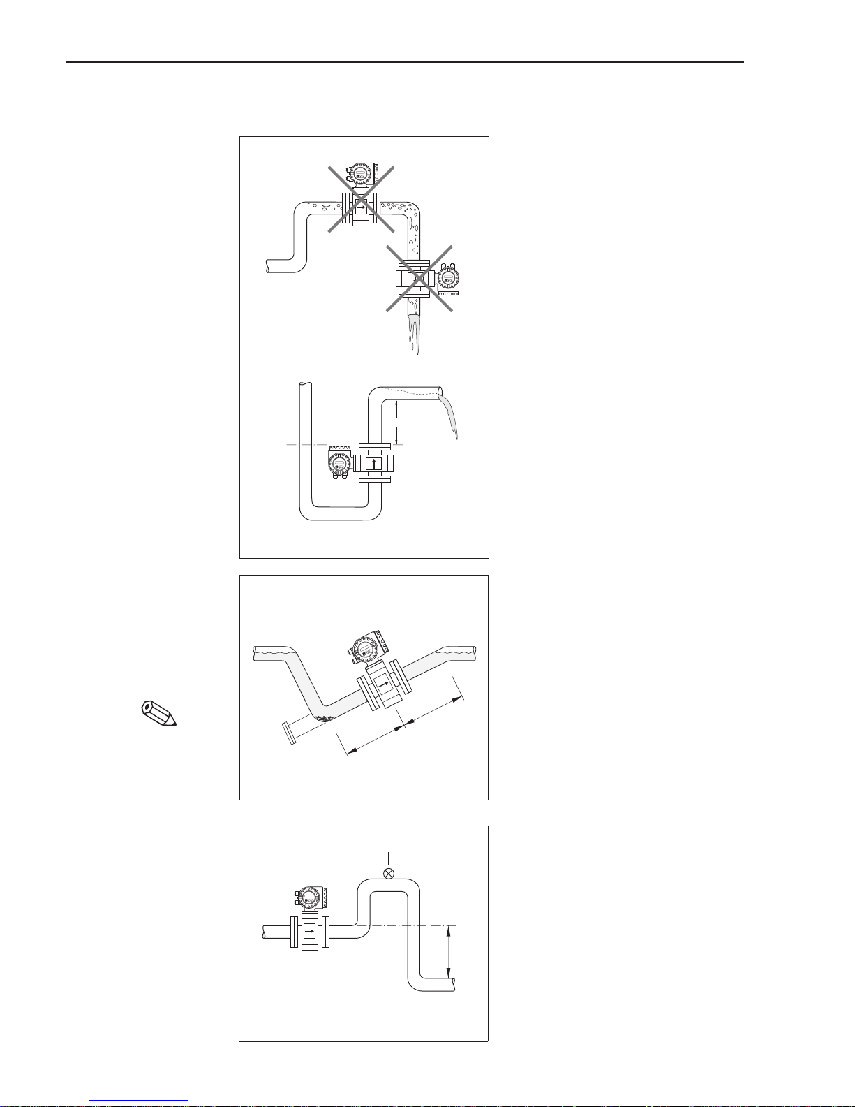
3.2 Mounting location
Correct measurement is only possible
when the pipe is full. The following
locations should therefore be avoided:
• No installation at the highest point
(air accumulation).
• No installation immediately before
an open pipe outlet in a downward
line.
The alternative installation, however,
enables correct measurement.
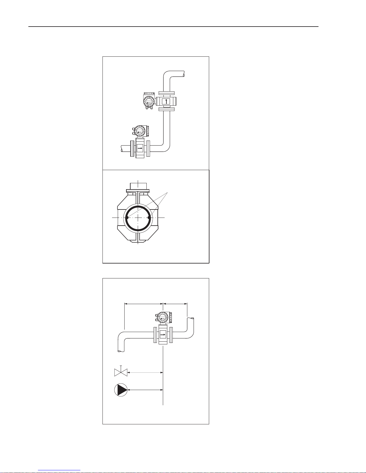
Partly filled pipes
For inclines a mounting similar to a drain
should be adopted.
Added security is offered by Empty Pipe
Detection in order to detect empty or
partly filled pipes (see page 73).
Note!
Danger of solids accumulation!
Do not mount the sensor at the lowest
point of the drain. A cleaning valve
should also be installed.
Downward pipe
With the installation suggested opposite,
partial vacuum is avoided even with a
downward pipe > 5 m long (siphon, vent
valve downstream of the sensor).
h 2 x DN≥
alternatively
ba009y13
Fig. 5
Mounting location
≥ 5xDN
≥ 2 x DN
ba009y14
Fig. 6
Mounting with a partly filled pipe
>5m
ba009y15
Venting valve
Fig. 7
Installation downward pipe
Note!
3 Mounting and Installation Promag 33
10 Endress+Hauser
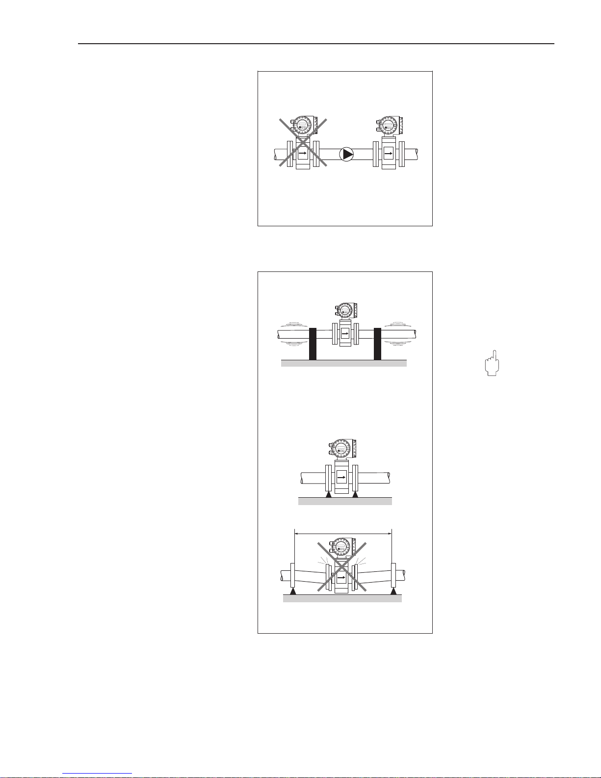
Installation of pumps
Do not mount the sensors on the
suction side of pumps. This prevents
low pressure and therefore possible
damage to the lining of the measuring
tube.
Information on the resistance to vacuum
of the flowmeter lining can be found on
page 115.
Pulse dampers should be installed
when using reciprocal, diaphragm or
peristaltic pumps.
Vibration
The piping before and after the sensor
should be securely fastened if there
is excessive vibration.
Information on shock and vibration
resistance is found on page 110.
Caution!
Excessive vibration necessitates
separate mounting of the sensor and
transmitter (see pages 20, 109).
Mechanical support of the sensor is
recommended for free runs of piping
over 10 m long.
Caution!
ba009y16
Fig. 8
Installation of pumps
> 10 m
ba009y11
Fig. 9
Ways to avoid vibrations
Promag 33 3 Mounting and Installation
Endress+Hauser 11
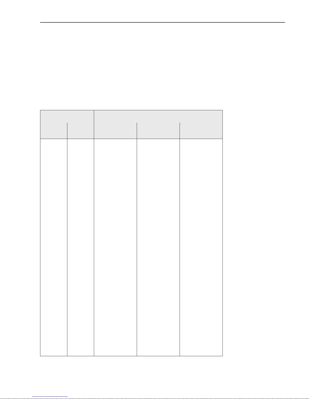
3.3 Mounting position
Vertical mounting:
This is the recommended position with
the flow upwards. Entrained solid
particles sink and fatty components in
the stationary fluid rise away from the
measuring electrodes. This is the
optimal position in empty pipe system
and when using Empty Pipe Detection
(see page 73).
Horizontal mounting:
The axis of the electrodes must be
horizontal, thus preventing brief insulation of the electrodes by entrained air
bubbles.
Electrode axis:
The plane in which the electrode axis
lies with regard to the transmitter is
identical for the Promag A, H and F
sensors.
Inlet and outlet sections
The sensor should by mounted away
from fittings such as valves, T-pieces,
elbows, etc.
Inlet section: ≥ 5 x DN
Outlet section: ≥ 2 x DN
The inlet and outlet sections must be
observed in order to maintain accuracy.
ba009y10
Measuring
electrodes
Electrode axis
(Example Promag F)
ba009y09
Fig. 10
Mounting position (horizontal,
vertical)
≥ 5 x DN ≥ 2 x DN
ba009y12
Fig. 11
Inlet and outlet sections
3 Mounting and Installation Promag 33
12 Endress+Hauser
3.4 Nominal diameter and flow rate
The diameter of the pipe usually governs the nominal diameter of the sensor.
The optimum flow velocity range is between v = 2...3 m/s. Furthermore, the flow
velocity (v) has to be matched to the physical properties of the fluid:
• v < 2 m/s → with abrasive fluids (potter’s clay, lime milk, ore slurry)
• v > 2 m/s → with fluids forming coating (wastewater sludge, etc.)
If it is necessary to increase the flow velocity, this can be done by reducing the
nominal diameter of the sensor (see following chapter).
DN Full scale values in [m3/h]
[mm] [inch]
Minimum value
at v = 0.3 m/s
Factory setting
at v ~ 2.5 m/s
Maximum value
at v = 10 m/s
2
4
8
15
25
32
40
50
65
80
100
125
150
200
250
300
350
400
450
500
600
700
750
800
900
1000
1050
1200
1350
1400
1500
1600
1700
1800
2000
1
/12"
5/
32
"
5
/16"
1
/2"
1"
1
1
/4"
1
1
/2"
2"
2
1
/2"
3"
4"
5"
6"
8"
10"
12"
14"
16"
18"
20"
24"
28"
30"
32"
36"
40"
42"
48"
54"
56"
60"
64"
66"
72"
78"
0.0034
0.0136
0.0543
0.1908
0.5301
0.8685
1.357
2.121
3.584
5.429
8.482
13.25
19.09
33.93
53.01
76.34
103.9
135.7
171.8
212.1
305.4
415.6
477.1
542.9
687.1
848.2
935.2
1222
1546
1663
1909
2172
2451
2748
3393
0.0283
0.1131
0.4524
1.590
4.418
7.238
11.31
17.67
29.87
45.24
70.69
110.5
159.0
282.7
441.8
636.2
865.9
1131
1431
1767
2545
3464
3976
4524
5726
7069
7793
10179
12882
13854
15904
18096
20428
22902
28274
0.1131
0.4524
1.810
6.362
17.67
28.95
45.24
70.69
119.5
181.0
282.7
441.8
636.2
1130
1767
2545
3464
4524
5726
7069
10179
13854
15904
18096
22902
28274
31172
40715
51530
55418
63617
72382
81713
91609
113097
Promag 33 3 Mounting and Installation
Endress+Hauser 13
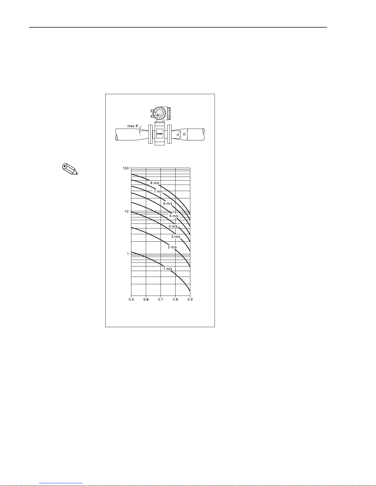
3.5 Adapters
The sensor can also be mounted in a pipe with a larger nominal diameter when
suitable adapters (reducers and expanders) to DIN 28545 are fitted.
The resultant increase in the rate of flow increases the accuracy of measurement
with slowly moving fluids.
The adjacent nomogram can be used to
determine the pressure loss caused.
Procedure:
1. Determine the ratio of the
diameter d/D.
2. From the nomogram read off the
pressure loss at the flow velocity and
d/D ratio.
Note!
The nomogram applies to fluids with a
viscosity similar to that of water.
Diameter ratio d/D
Pressure loss [mbar]
ba009y17
Fig. 12
Pressure loss when using
adapters
Note!
3 Mounting and Installation Promag 33
14 Endress+Hauser
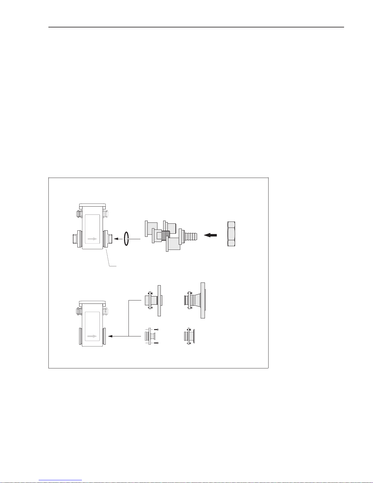
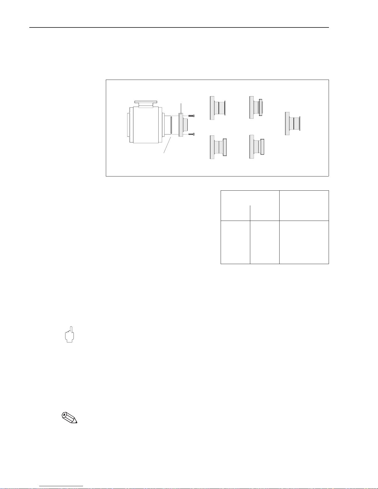
3.6 Mounting Promag A sensor
Various process connections are available for the Promag A sensor.
The process connections (adapters) are mounted in two ways:
A.
Coupling nut on a 1" threaded stub (mounting set)
• Internal thread
• External thread
• PVC adhesive coupling
• Hose connection
• Weld nipples
B.
Screw-in process connections (instead of threaded stub)
These process connections are mounted as standard in the factory before delivery.
• Flange joints
• Tri-Clamp
Seals / Screw tightening torques (Mounting set)
When fastening the process connections, the O-ring or the flat seal is pressed fully
into the seal groove in the threaded stub. The skirted nut thereby comes to a fixed
stop.
Length, Dimensions → see pages 99 ff.
Flange joints
(mounted when
delivered)
Tri-Clamp
(mounted when
delivered)
Can be ordered separately as mounting set:
Internal thread, external thread, PVC adhesive coupling,
hose connection, welded nipples
1" threaded stub (ISO 228)
DN 2...25
ba009y18
A
B
DN 2...25
Fig. 13
Process connections
Promag A
Promag 33 3 Mounting and Installation
Endress+Hauser 15
3.7 Mounting Promag H sensor
The Promag H sensor is delivered with the process connection already mounted.
The various process connections are fastened to the sensor with 4 or 6 screws.
Seals / Screw tightening torques
When mounting the process connectors,
make sure that the seal is free of dirt
and correctly centered. The screws have
to be tightened.
The process connector forms a metal
connection with the sensor, to guarantee
a pre-defined seal compression.
The gaskets must be replaced at
frequent intervals!
Length, Dimensions → see pages 102 ff.
Welding the sensor into the pipework (welded nipple)
If the sensor is directly welded into the pipework, we recommend the following
procedure:
Caution!
The electronics may be destroyed! Take care that the welding ground is not via
the Promag 33 H sensor or housing.
1. Fasten the Promag H sensor with some spot welds into the pipe.
2. Loosen the screws at the process-connector flange and remove the sensor from
the pipe; make sure that the seal is also removed from the process connector.
3. Weld the process connector into the pipe.
4. Once again install the sensor into the pipe; making sure everything is clean and
the seal is correctly positioned.
Note!
• If the welding process is correctly executed in thin-walled food piping, the seal will
not be damaged by the heat, even when mounted. Nevertheless, we recommend removing the sensor and seal first.
• For the disassembly, the pipe has to be spread by about 4 mm.
Caution!
Note!
ba009y19
Promag H
Flat seal
Silicone / EPDM
Welded nipple
Tri-Clamp
DIN 11851
ISO 2853
SMS
ISO 2852
Fig. 14
Process connections
Promag H
Diameter Max.
tightening torque
DIN
[mm]
ANSI
[inch]
[Nm]
25
40
50
65
80
100
1"
1
1
/2"
2"
2
1
/2"
3"
4"
10
10
25
25
88
88
3 Mounting and Installation Promag 33
16 Endress+Hauser
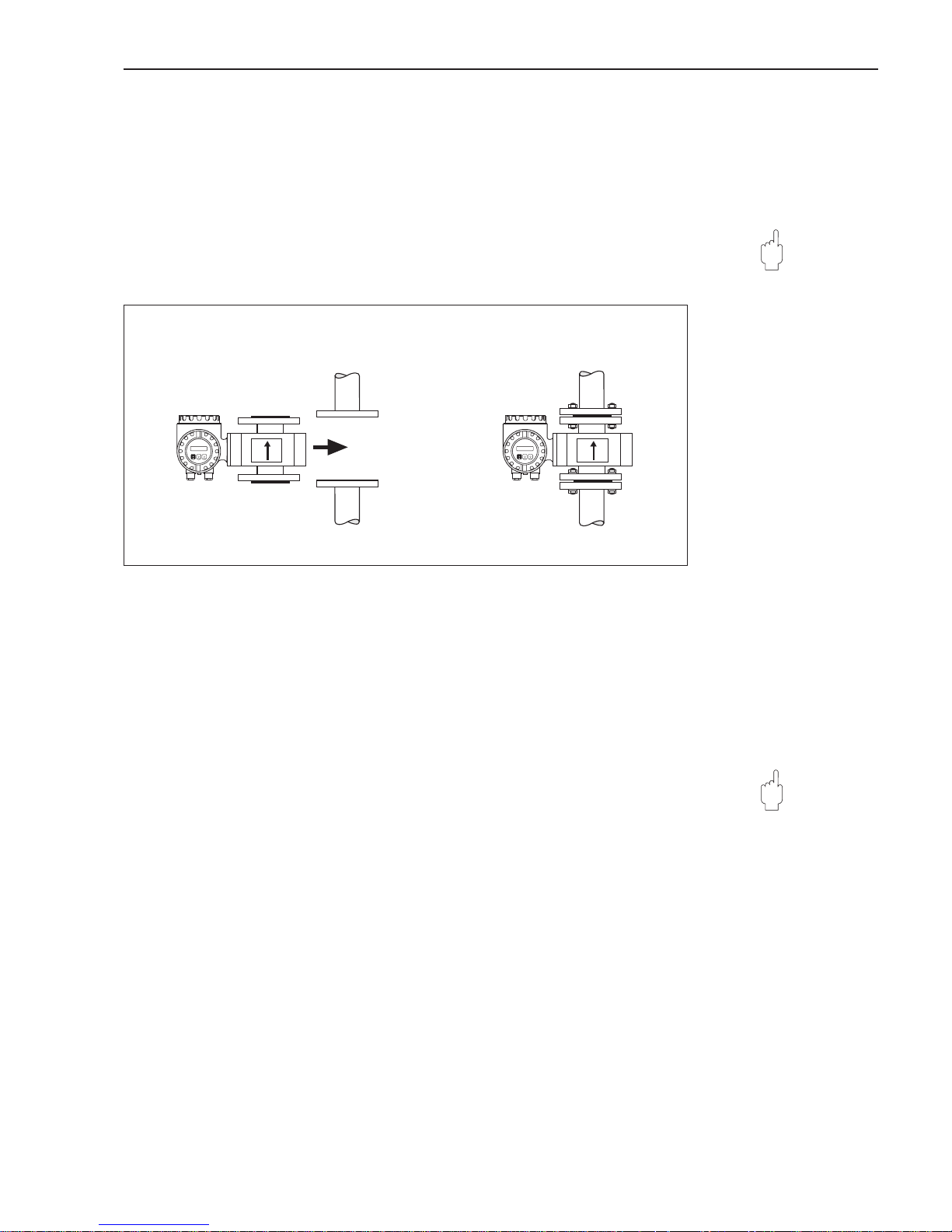
3.8 Mounting Promag F sensor
The sensor is mounted between the flanges of the piping (Fig. 15). Since the lining of
the measuring tube also covers the sensor flange, it also acts as a seal.
Caution!
The Teflon (PTFE) lined Promag F is fitted with protective disks to guard the lining
which is turned over the flanges. These disks are to be removed just before mounting
the sensor. Ensure that the lining on the flange is not damaged or removed.
These disks must remain in position during storage.
Seals
• If the measuring tube liner is made of soft rubber or Teflon (PTFE), a flange seal
is not required.
• With soft rubber lining the mating flange should have a thin film of non-conductive
sealing grease applied.
• Use a seal according to DIN 2690.
• Mounted seals must not protrude into the piping section.
Caution!
Danger of short-circuit! Do not use sealing materials that are electrically conductive,
e.g. graphite. This could result in an electrically conductive layer forming on the inside
of the measuring tube and therefore short-circuiting the measuring signal.
Screw tightening torques → see following page
Length, Dimensions → see pages 104, 105
Caution!
Caution!
ba009y20
Fig. 15
Mounting Promag 33 F
Promag 33 3 Mounting and Installation
Endress+Hauser 17
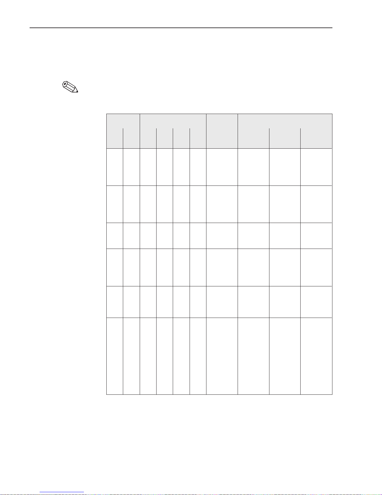
Screw tightening torques (Promag F)
The tightening torques listed apply to greased threads.
Screws tightened up too tightly deform the sealing surface. Special attention should
be paid to soft rubber linings.
Note!
The tightening torques given here apply only to those pipes which are not subject
to mechanical stress.
Note!
Diameter Pressure ratings Screws Max. tightening torques [Nm]
[mm] [inch] DIN
[bar]
ANSI
[lbs]
AWWA JIS Hard rubber Soft rubber
(EPDM)
PTFE
(Teflon)
15
25
32
40
50
1
/2"
1"
–
1
1
/2"
2"
PN 40 Class
150
–
20K
20K
20K
20K
10K
4xM12
4xM12
4xM12
4xM16
4xM16
–
25
40
50
64
–
5
8
11
15
15
33
53
67
84
65
80
100
125
150
–
3"
4"
–
6"
PN 16 Class
150
–
10K
10K
10K
10K
10K
4xM16
8xM16
8xM16
8xM16
8xM20
87
53
65
80
110
22
14
22
30
48
114
70
85
103
140
200
250
300
8"
10"
12"
PN 10 Class
150
–
10K
10K
10K
8 x M 20
12 x M 20
12 x M 20
108
104
119
53
29
39
137
139
159
350
400
500
600
14"
16"
18"
20"
24"
PN
10/16
Class
150
–
16 x M 20
16 x M 24
20 x M 24
20 x M 24
20 x M 27
141/193
191/245
170/251
197/347
261/529
39/79
59/111
58/111
70/152
107/236
188/258
255/326
227/335
262/463
348/706
700
800
900
1000
28"
30"
32"
36"
PN
10/16
– Class
D
24 x M 27
24 x M 30
28 x M 30
28 x M 33
312/355
417/471
399/451
513/644
122/235
173/330
183/349
245/470
–
–
–
–
1200
–
1400
–
1600
–
1800
–
2000
48"
54"
–
60"
–
66"
72"
78"
–
PN 6 – Class
D
32 x M 36
36 x M 39
36 x M 39
40 x M 45
40 x M 45
44 x M 45
44 x M 45
48 x M 45
48 x M 45
720
840
840
1217
1217
1238
1238
1347
1347
328
432
432
592
592
667
667
749
749
–
–
–
–
–
–
–
–
–
3 Mounting and Installation Promag 33
18 Endress+Hauser
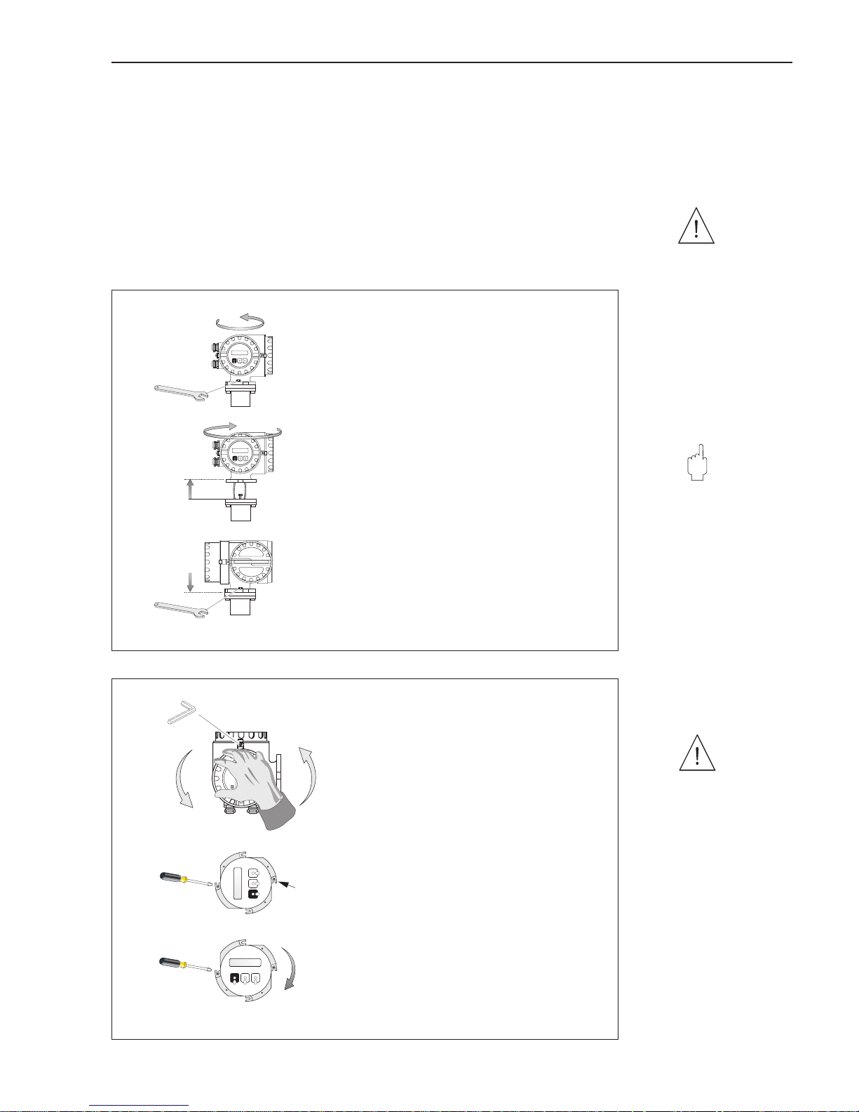
3.9 Turning the transmitter housing and local display
The transmitter housing and local display can be rotated in steps of 90°. This enables
the unit to be adapted to different mounting positions in the piping and so simplifying
reading and operation.
Warning!
For instruments with EEx d/de or FM/CSA Cl. I Div. 1 approval, the procedure for
rotating the instrument is different than that described here and is given in the
Ex-supplement to this documentation.
Warning!
30
o
Turning the transmitter housing
1. Loosen the two fixing screws of the transmitter
bayonet catch (approx. two turns)
2. Turn the bayonet catch of the transmitter as far
as the screw slits (approx. 15 mm).
3. Carefully lift the transmitter housing to the stop.
Caution!
Do not damage the cable between
the transmitter and sensor!
4. Turn the transmitter housing to the desired
position.
5. Lower the housing and engage the bayonet
catch.
6. Retighten the two screws.
ba009y22
1
2
3
4
6
5
Fig. 16
Turning the transmitter housing
ENDRESS+HAUSER
PROMAG33
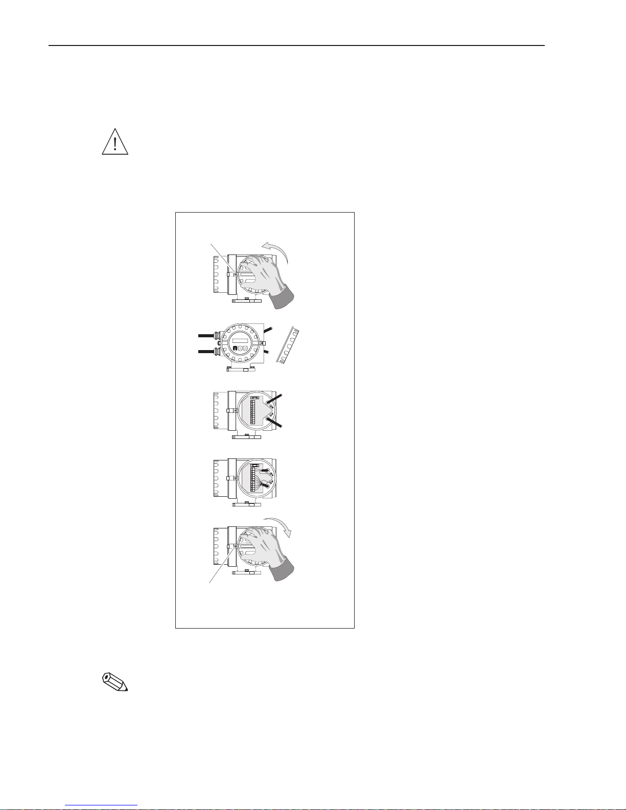
Turning the local display
Warning!
Danger from electric shock! Switch off the
power supply before opening the instrument.
1. Loosen the Allen screw of the safety grip
(3 mm Allen key).
2. Unscrew the cover of the electronics area
of the transmitter housing.
3. Unscrew the two Phillips screws of the front
panel display.
4. Turn the display module to the required position.
5. Securely tighten the Phillips screws.
6. Replace and screw down securely the cover of
the electronics area on to the transmitter housing.
7. Securely tighten the Allen screw of the safety grip.
1
2
3
5
6
4
7
ba009y23
Fig. 17
Turning the local display
Warning!
Caution!
Promag 33 3 Mounting and Installation
Endress+Hauser 19
3.10 Mounting the transmitter (remote version)
The transmitter has to be mounted remote from the sensor when:
• access is difficult,
• space is restricted,
• extreme process and ambient temperatures prevail (for temperature ranges
see page 110),
• there is severe vibration (> 2 g/2 h per day; 10...100 Hz).
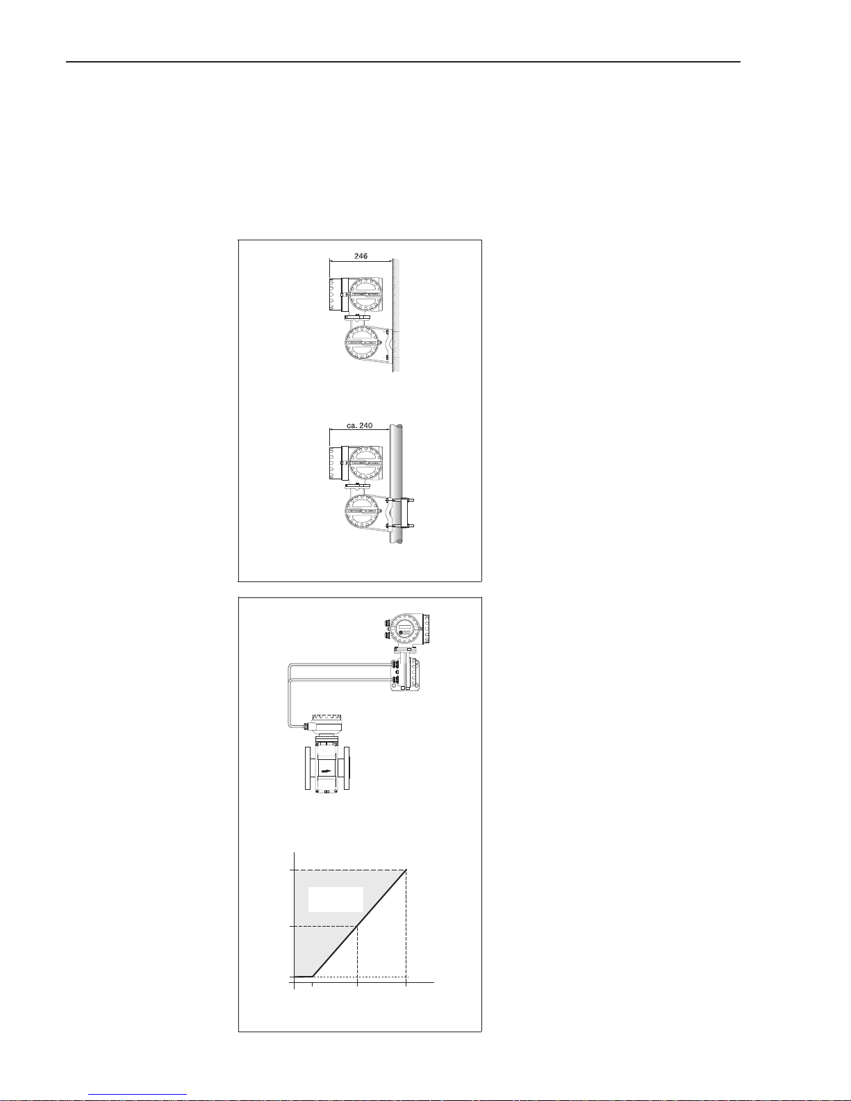
Wall and post mounting
The remote mounted version is delivered
with a wall bracket as standard.
A special mounting set can be supplied
for post mounting: Order No. 50076905.
Connecting cable
Two different versions are available
for remote versions:
FS version:
• The permissible length of cable
L
max
of more than 10 m is governed
by the conductivity of the fluid
(see Fig. 19).
• The maximum possible cable length is
limited to 10 meter for instruments with
Empty Pipe Detection (EPD). This
function is only available with the
FS version.
• The FS cable is recommended only for
distances smaller than 20 m.
FL version:
• All fluids with a minimum conductivity
of ≥ 5 µS/cm (demineralised water
≥ 20 µS/cm) can be measured.
This is not dependent on the distance
between transmitter and sensor
(see Fig. 19).
• Empty Pipe Detection (EPD) is
not
available with this version.
Please also note the following for
obtaining correct readings:
• Fasten the cable gland or lay it in a
conduit. When the fluid conductivity is
low, cable movements can cause
serious changes in capacitance and
thereby falsify the measuring signal.
• Do not run the cable in the vicinity of
electrical machines or switching
elements.
• Ensure potential equalisation between
the transmitter and the sensor.
Wall mounting
Post mounting (∅ 3/4...3")
ba009y29
Fig. 18
Wall and post mounting
200
100
5
10 100 200 [m]
FL
FS
Conductivity
[µS/cm]
Cable length L
max
ba009y24
L
max
Permissible
range
Fig. 19
Fluid conductivity and cable
length with the remote version
3 Mounting and Installation Promag 33
20 Endress+Hauser
4 Electrical Connection
Warning!
• When connecting Ex-approved instruments, please observe all instructions and
wiring diagrams given in the Ex supplement to this Operating Manual.
Your E+H representative will be pleased to provide you with more information.
• When using the remote version, only sensors and transmitters with the same serial
number are to be connected together. Measuring errors can occur if this is not the
case.
4.1 Degree of protection
The instruments fulfil all the requirements for IP 67. After successful installation in the
field or after servicing, the following points must always be observed in order to
ensure the degree of protection IP 67:
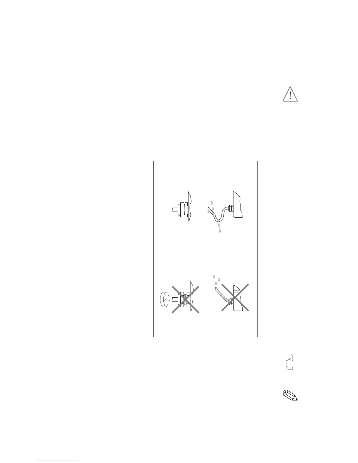
• Housing seals must be clean and
undamaged when inserted in the seal
groove. The seals may need to be
dried, cleaned or replaced.
• All housing screws and the housing
cover must be tightened firmly.
• The cables used for connecting must
have the correct outer diameter (see
page 27).
• The cable gland must be tightened
firmly (see Fig. 20).
• The cable must loop down before
entering the cable gland to ensure
that no moisture can enter it (see
Fig. 20).
Install the sensor so that the cable
glands first hang down and do not first
go upwards.
• Any cable gland not used must be
replaced with a blind plug.
• The protective bushing should not be
removed from the cable gland.
Caution!
The screws of the Promag sensor housing must not be loosened or the degree of
protection guaranteed by E+H is no longer valid.
Note!
The Promag A and F sensors can optionally be supplied with the IP 68 degree of
protection (permanently under water to a depth of 3 m). In this case the transmitter
(IP 67) has to be mounted remote from the sensor.
Warning!
Caution!
Note!
ba009y06
Correct!
Incorrect!
Fig. 20
Mounting cable entries
Promag 33 4 Electrical Connection
Endress+Hauser 21
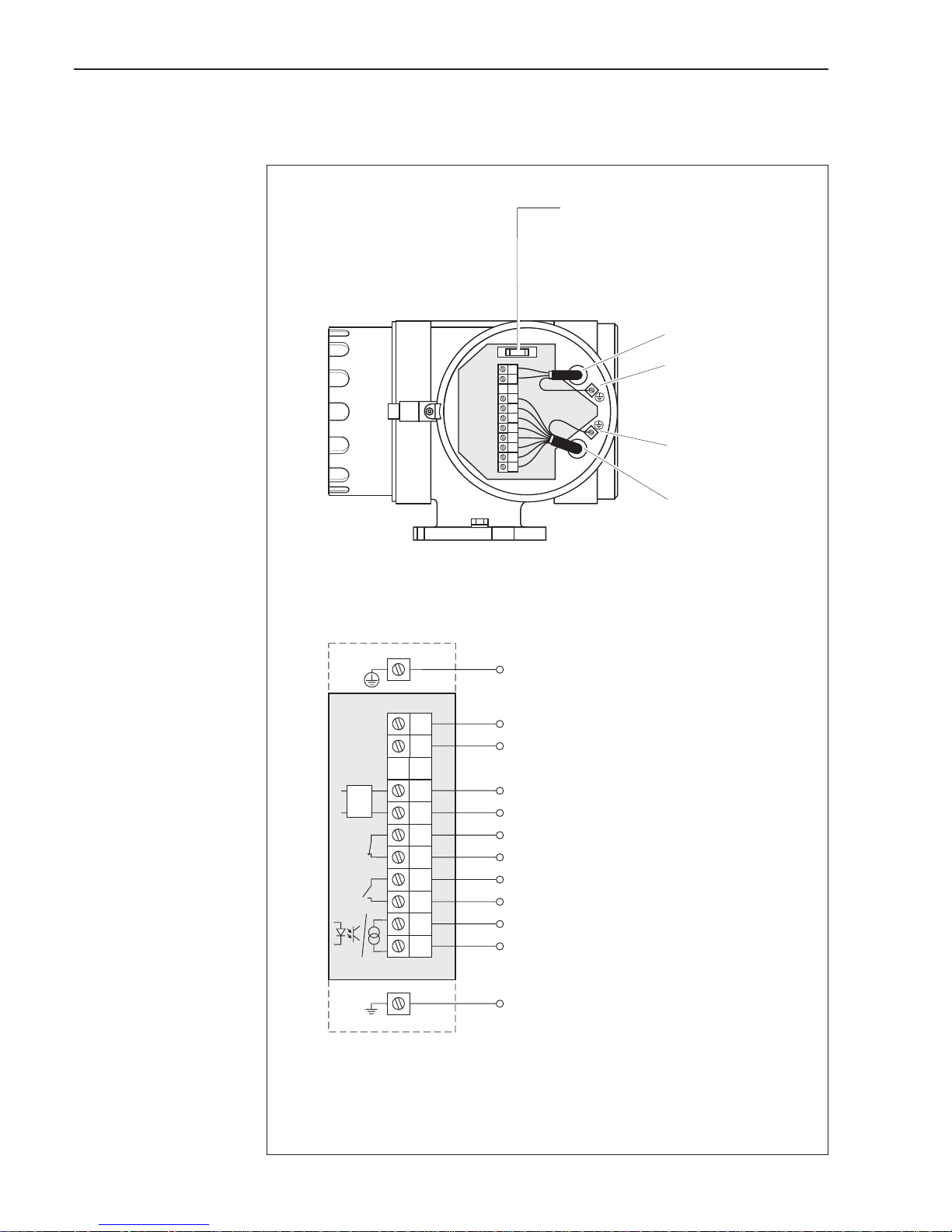
4.2 Connecting the transmitter
Warning!
• Risk of electric shock! Switch off the power supply before opening the instrument.
Do not install or wire the unit while connected to the power supply. Failure to comply
may also result in damage of electronic components.
• Connect the protective conductor to the ground terminal on the housing before the
power supply is switched on.
• Check that local power supply and frequency agree with the information on the
nameplate. All relevant national regulations for mounting must also be observed.
1. Loosen the Allen screw of the safety
grip using an 3 mm Allen key.
2. Unscrew the wiring compartment cover.
3. Feed the power and signal cables
into the appropriate cable glands.
4. Wire up according to the wiring
diagrams:
→ see Fig. 22, 23 or
→ Wiring diagram in the screw cover
• Power supply is connected
to terminal 1 (L1, L+), terminal 2
(N, L–) and the ground terminal (3).
• Fine-wire leads: max. 4 mm
2
;
put sleeve on the end of the cores.
Single-core lead: max. 6 mm
2
.
5. Having made the connection,
screw the cover tightly again on the
transmitter housing.
6. Tighten the Allen screw of the safety
grip securely.
Note!
For instruments fitted with an “EEx i” communications module, the electrical
connection is described in separate Ex documentation.
Warning!
Note!
ANSCHLUSSKLEMMEN - FIELDTERMINALS
3
28
+
+
-
-
+
+
+
-
20
21
23
24
25
26
27
1
2
22
3
28
+
+
-
-
+
+
+
-
20
21
23
24
25
26
27
1
2
22
ANSCHLUSSKLEMMEN - FIELDTERMINALS
Supply cable
ba009y30
Signal cable
➊
➋
➌
➌
➍
➎
➏
Fig. 21
Connecting the transmitter
4 Electrical Connection Promag 33
22 Endress+Hauser
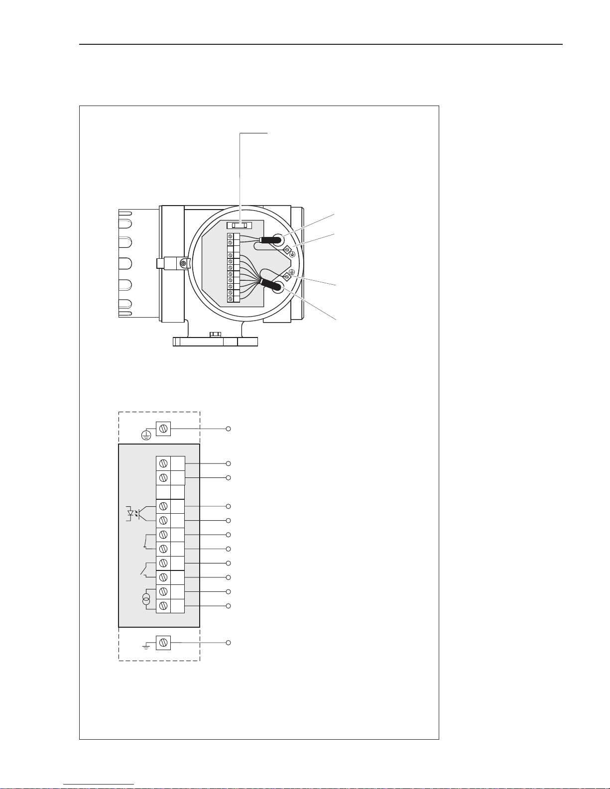
Connection diagram for the transmitter (“HART”)
3
28
20
21
23
24
25
26
27
1
2
22
+
-
+
-
+
-
+
-
1
2
3
28
20
21
22
23
24
25
26
27
Supply cable
Ground terminal for
protective conductor
Ground terminal for
signal cable shield
Signal cable
ba009y35
Fuse
• Power supply 20...55 V AC / 16...62 V DC:
2.5 A slow-blow / 250 V; 5.2 × 20 mm
• Power supply 85...260 V AC:
1 A slow-blow / 250 V; 5.2 × 20 mm
Ground connection (protective earth)
L1
for AC power supply
L+
for DC power supply
NL–
Pulse/frequency output (active/passive): f
max
= 10 kHz
active: 24 V DC, 25 mA (max. 250 mA/20 ms)
passive: 30 V DC, 250 mA
Alarm output (Relay 1): can be configured
max. 60 V AC / 0.5 A AC; max. 30 V DC / 0.1 A DC
Current output (active):
0/4...20 mA, R
L
< 700 Ω (with HART: RL≥ 250 Ω)
Ground connection (screening of signal cable)
The input and outputs are galvanically isolated from the power supply and
from each other.
Version with a “HART”communication module
Status output (Relay 2): can be configured
max. 60 V AC / 0.5 A AC; max. 30 V DC / 0.1 A DC
Fig. 22
Terminal compartment
Promag 33 (HART)
Promag 33 4 Electrical Connection
Endress+Hauser 23
Connection diagram for the transmitter (“RS 485”)
3
28
20
21
23
24
25
26
27
1
2
22
+
-
+
-
+
-
+
-
1
2
3
28
20
21
22
23
24
25
26
27
Supply cable
Ground terminal for
protective conductor
Ground terminal for
signal cable shield
Signal cable
ba009y32
Fuse
• Power supply 20...55 V AC / 16...62 V DC:
2.5 A slow-blow / 250 V; 5.2 × 20 mm
• Power supply 85...260 V AC:
1 A slow-blow / 250 V; 5.2 × 20 mm
Ground connection (protective earth)
L1
for AC power supply
L+
for DC power supply
NL–
Alarm output (Relay 1): can be configured
max. 60 V AC / 0.5 A AC; max. 30 V DC / 0.1 A DC
Ground connection (screening of signal cable)
Versionwith a “RS 485”communication module
Status output (Relay 2): can be configured
max. 60 V AC / 0.5 A AC; max. 30 V DC / 0.1 A DC
RS 485 interface
or *
Auxiliary input
A + / –
3...30 V DC
B – / +
Current output (active): 0/4...20 mA, R
L
< 700 Ω
or *
Pulse/frequency output (active/passive): f
max
= 10 kHz
active: 24 V DC, 25 mA (max. 250 mA/20 ms)
passive: 30 V DC, 250 mA
* Only one version is possible for each, depending on the setting selected in
the function “SYSTEM CONFIG.” (see page 71).
The input and outputs are galvanically isolated from the power supply and
from each other.
Fig. 23
Terminal compartment
Promag 33 (RS 485)
4 Electrical Connection Promag 33
24 Endress+Hauser
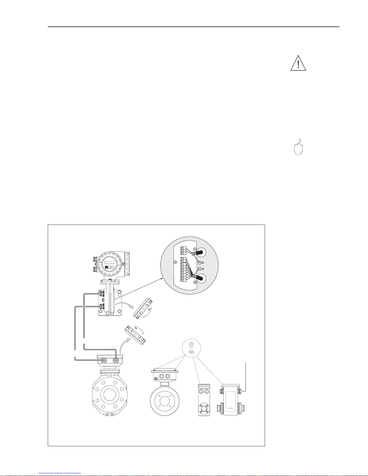
4.3 Connecting the cable of the remote version
Warning!
Danger from electric shock! Switch off the power supply before opening
the instrument.
1. Loosen the safety grip and remove the cover of the
transmitter housing
.
2. Remove the cover from the
connection housing of the sensor
:
– Promag A, H: Loosen all the Phillips screws
– Promag F: Loosen the safety grip and unscrew the cover.
3. Feed both signal and coil-current cable into the appropriate cable entries
of the connection housings.
Caution!
Danger of destroying the coil current control! Only connect or disconnect
the coil cable once the power supply to the instrument has been switched off.
4. Connect the sensor / transmitter cable according to the wiring diagrams
(see Fig. 25).
5. Retighten the connection housing cover securely.
With Promag F, the Allen screw of the safety grip also has to be tightened.
Warning!
Caution!
42
41
22
23
36
37
4
8
7
5
6
Transmitter
ba009y31
➊➎
➋➎
➌
➍
Signal cable
Coil current cable
FS FL
Coil current
cable
Promag F Promag H
Sensors
Promag A
Fig. 24
Connecting the transmitter /
sensor cable
Promag 33 4 Electrical Connection
Endress+Hauser 25
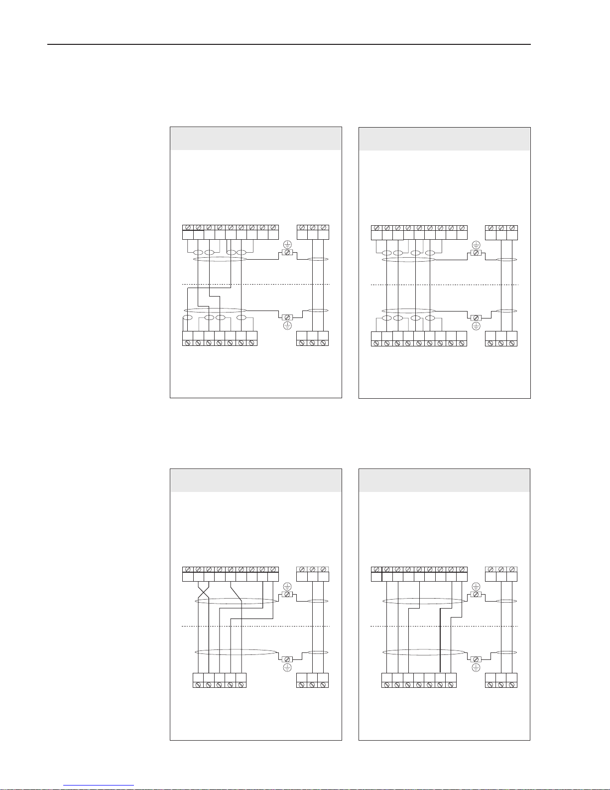
Wiring diagrams for the remote version (FS/FL)
6
6
557
7
8
8
4
4
37373636232322
22
424241
41
S1S1E1E1E2
E2
S2
S2
GND
GND
E
E
S
S
EPD
EPD
Coils
Coils
2
1
brown
white
green
yellow
6
64
557
7
8
8
4
3737363623 22
424241
41
S1S1E1E1E2
E2
S2
S2
GND
GND
E
E
S
S
EPD
EPD
Coils
Coils
2
1
brown
white
green
yellow
6
557
7
8
4
4
37373636232322
22
424241
41
E1E1E2
E2
GND
GND
Coils
Coils
2
1
white
V+ V-
V+ V-
grey
green
brown
yellow
6
577
5
8
4
4
37 36 232322
22
424241
41
E1
E1E2E2
GND
GND
Coils
Coils
2
1
V+
V-
V+ V-
grey
brown
white
yellow
green
out-out+
Promag 33 A
Transmitter Transmitter
Sensor Sensor
Sensor
Sensor
Transmitter Transmitter
Remote version “FS”
Promag 33 H / F
Promag 33 A Promag 33 H / F
Remote version “FL”
ba009e01
Fig. 25
Wiring diagrams for the remote
“FS” and “FL” versions
4 Electrical Connection Promag 33
26 Endress+Hauser

4.4 Cable specifications
Remote version “FS”
Coil cable: 2 x 0.75 mm
2
PVC cable with common screen *
Conductor resistance ≤ 37 Ω/km
Capacitance: core/core, screen grounded ≤ 120 pF/m
Permanent operating temperature: –20...+70 °C
Signal cable: 3 x 0.38 mm
2
PVC cable with common screen *
and separately screened cores
With EPD (Empty Pipe Detection) 4 x 0.38 mm
2
PVC cable
Conductor resistance ≤ 50 Ω/km
Capacitance: core/screen ≤420 pF/m
Permanent operating temperature: –20...+70 °C
* braided copper screen: ∅ ~7mm
Remote version “FL”
Coil cable: 2 x 0.75 mm
2
PVC cable with common screen *
Conductor resistance ≤ 37 Ω/km
Capacitance: core/core, screen grounded ≤ 120 pF/m
Permanent operating temperature: –20...+70 °C
Signal cable: 5 x 0.5 mm
2
PVC cable with common screen *
Conductor resistance ≤ 37 Ω/km
Capacitance: core/core, screen grounded ≤120 pF/m
Permanent operating temperature: –20...+70 °C
* braided copper screen (coil cable ∅ ~ 7 mm; signal cable ∅ ~ 9 mm)
Operation in areas with severe electrical interference
The Promag 33 measuring system fulfils all general safety requirements according
to EN 61010 and electromagnetic compatibility (EMC) according to EN 50081 Part 1
and 2 / EN 50082 Part 1 and 2 when installed in accordance with the NAMUR
recommendations.
Note!
• Remote version:
To comply with the certificate of conformity, the signal and coil cables between the
sensor and transmitter must always be screened and grounded at both ends.
Grounding is made using the ground terminals especially for this purpose on the
inside of the connection housings. Keep stripped and twisted cable shield section
to the ground terminal as short as possible!
• The cable must be resistant to an ambient temperature of max. +80 °C if the
Promag H sensor is operated at a process temperature of +150 °C.
Note!
Promag 33 4 Electrical Connection
Endress+Hauser 27
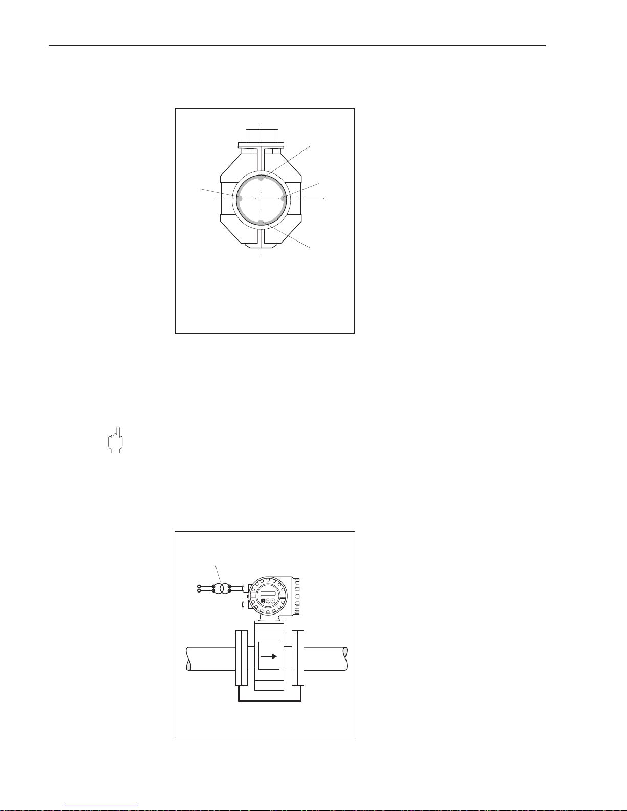
4.5 Potential equalisation
The sensor and the fluid must have
roughly the same electrical potential to
ensure that measurement is accurate
and no galvanic corrosion takes place at
the electrode. Normally the reference
electrode in the sensor or the metal pipe
ensures that the potentials are equalised.
Reference electrodes:
• Promag A:
always with reference electrode
• Promag F:
optional, depending on material
• Promag H:
no reference electrode, as there is
always a metallic connection to the
fluid.
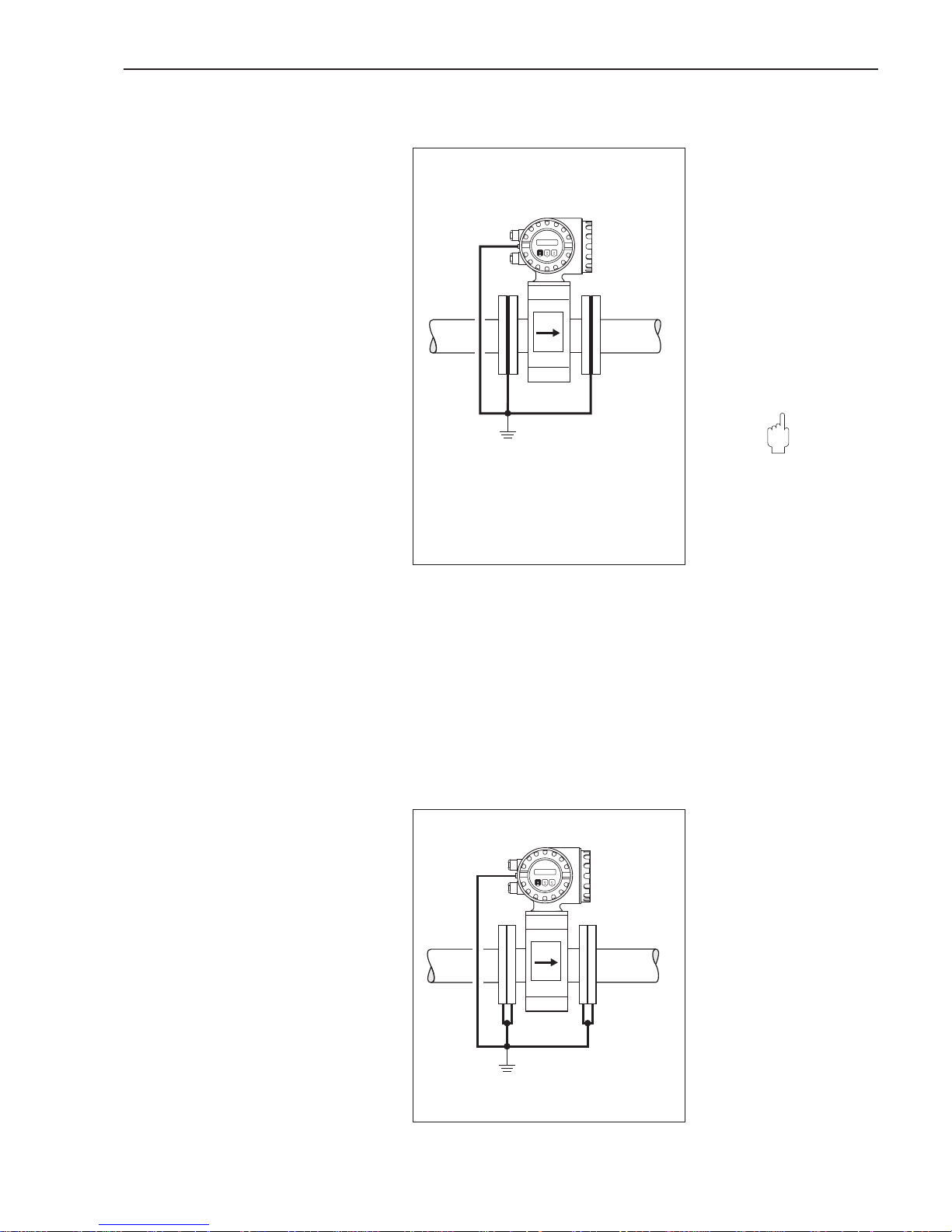
If the reference electrode is correctly grounded and the fluid flows through metallic,
non-lined and grounded piping, then it is sufficient to connect the grounding terminal
of the Promag 33 transmitter housing to the potential equalisation line in order to prevent corrosion. The connection with the remote-mounted version is made at the
ground terminal of the connection housing.
Caution!
Danger of permanent damage to the instrument! If the fluid cannot be grounded for
operational reasons, ground disks are to be used.
Potential equalisation for some special cases is described below:
Potential equalisation for lined pipes
with cathodic protection
When the fluid cannot be grounded for
operational reasons, the measuring unit
must be installed that it is potential-free
(Fig. 27). Ensure that components of the
piping are connected to one another
(copper wire, 6 mm
2
).
All national regulations regarding
potential free installation are to be
observed (e.g. VDE 0100).
Ensure that the mounting material used
does not result in a conductive bond with
the measuring unit and that the material
can withstand the tightening torque
used.
Caution!
ba009y25
1 Empty pipe detection electrode
2 Measuring electrodes
3 Reference electrode(s)
1
2
2
3
Fig. 26
Position of different electrodes
in the measuring tube
(Example: Promag 33 F)
6 mm² Cu
Isolating transformer
Power supply
ba009y26
Fig. 27
Potential equalisation for lined
pipes with cathodic protection
4 Electrical Connection Promag 33
28 Endress+Hauser
Plastic or lined piping
Ground disks must always be used with
non-conductive piping materials if compensation currents flow through the fluid.
They can irreparably damage the reference electrode within a short time due to
electrochemical corrosion.
Such conditions occur especially if:
• the piping is insulated with electrically
non-conductive materials and
• the piping is made of fibreglass or PVC
through which flow highly concentrated
acids and alkalis.
Caution!
Danger from damage due to electrochemical corrosion!
• Note the corrosion resistance of the
ground disks!
• Note the electrochemical potential se-
ries in cases where the ground disks
and the measuring electrodes are
made of different material.
Equalising currents in ungrounded metal pipes /
Grounding in an area with severe interference
The fluid may be grounded. In order to
make the most of the electromagnetic
compatibility (EMC) of the Promag 33,
it is advisable to provide two flange-toflange links and to connect them jointly
with the transmitter housing to ground
potential.
6 mm² Cu
Ground disks: appr. 3 mm thick
ba009y27
Fig. 28
Potential equalisation with plastic
or lined pipings.
6 mm² Cu
ba009y28
Fig. 29
Potential equalisation with
– equalising currents,
– in areas with severe
interference
Caution!
Promag 33 4 Electrical Connection
Endress+Hauser 29
4.6 Connecting E+H Rackbus and Rackbus RS 485
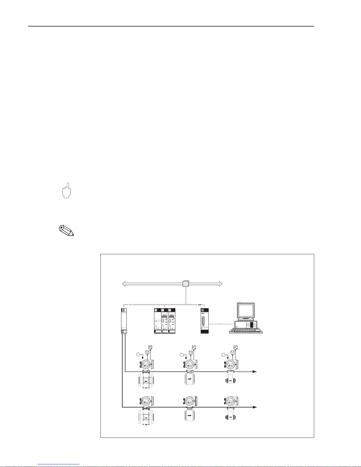
Promag 33 can be linked to other E+H measuring instruments using an
E+H-Rackbus and a Rackbus RS 485 and connected to higher process-control
systems such as MODBUS, PROFIBUS, ControlNet etc., with the help of a
corresponding gateway (see Fig. 30). A maximum of 64 addresses can be connected
to a ZA 672 gateway, including those connected to the FXA 675.
• E+H Rackbus (19" Racksyst cassette)
– For use in a control room up to a max. distance of 15 meters.
– A maximum of 64 addresses can be integrated into this bus via a ZA 672 gateway.
• Rackbus RS 485 (field housing)
– For use in the field up to a max. distance of 1200 meters.
– A maximum of 25 measuring instruments can be integrated
consecutively with the Rackbus RS 485 via FXA 675.
Commubox FXA 192 allows a direct connection to a PC (see Fig. 31).
Up to 25 Promag transmitters can be connected; however, the actual number
depends on the network topology and the application conditions.
Caution!
Even if only a single instrument (with Rackbus RS 485) has been installed in
hazardous area, not more than ten instruments (with Rackbus RS 485) may be
connected to the bus.
Note!
For the initial installation of a Rackbus network, please refer to the operating
instructions of the instruments and software you use, in particular:
• BA 134 F/00/e “Rackbus RS 485 – Topology, Components, Software”
• BA 124 F/00/en “Commuwin II operating program”
Caution!
Note!
ZA673
FXA675
u
u
u
RS 232C
Gateway ZA 672
FXA 675 E+H-Rackbus
Rackbus
RS 485
PROFIBUS, FIP, MODBUS,
INTERBUS, etc.
PC with E+H program
“Commuwin II” and a
ZA 672-DDE server
Gateway connection to PCs or process-controlsystems
ba009y75
Fig. 30
Connection versions to the
Rackbus RS 485 interface
4 Electrical Connection Promag 33
30 Endress+Hauser
 Loading...